You must be logged in to rate content!
18 minute(s) of a 37 minute read
1-11-2021
Callaway Turbo installation thread in a 1983 GTI
Compliments of jpawl @ www.vwvortex.com
The subject here is my 1983 Rabbit Gti which used to have a Callaway Stage II kit in it. The original owner moved from NY to CA and had it removed in 1985 at New Dimensions. I wanted the whole package when it went up for sale in 2001. I missed out on the car but got the Callaway parts. I installed them on a 1984 Rabbit Gti in 2003. In 2004, the Gti that you see here (that I missed out on) went up for sale. I was still obsessed about it so I bought it and had it shipped from San Jose, CA to Lexington, MA. Ever since I bought it, I always wanted to get a Callaway turbo kit back in it like it had before it went to CA in 1984. So finally, my friend Bill and I, who have three Callaway turbo installs between us, got started on it this past weekend.
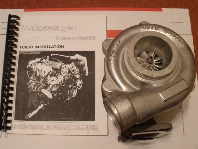
Rebuilt Roto-Master TO4B completed by Blaylock Turbo in Kansas. This instruction manual was used as a reference in my first install on my 1984 Rabbit Gti several years ago.
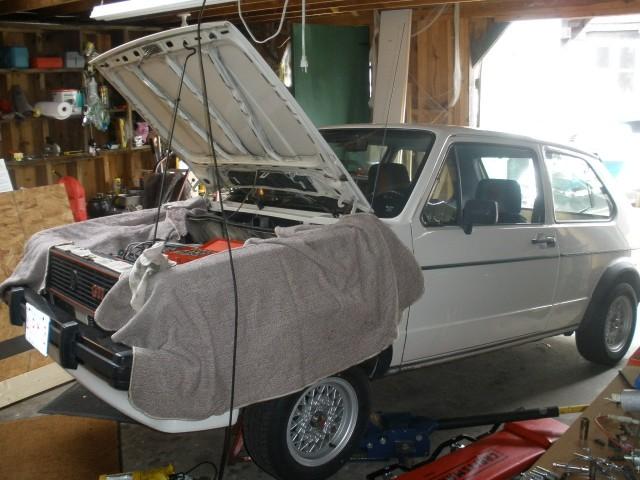
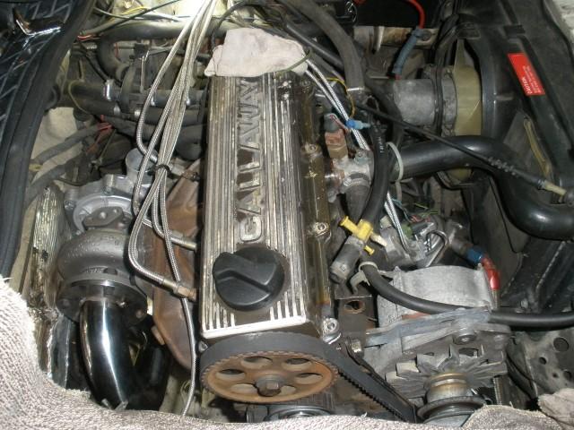
Twenty five years without the turbo. It is only fitting that a turbo goes back in.
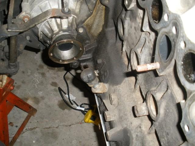
The back of the motor after the intake manifold, exhaust manifold, and axle removed. Note the drain plug tapped into the block that has been sealed off since 1985.
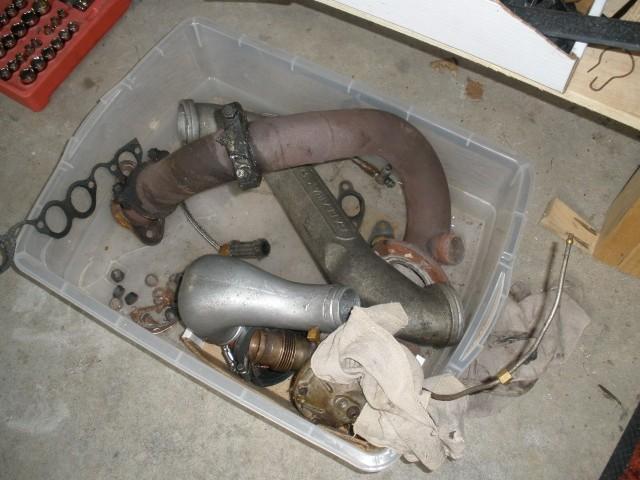
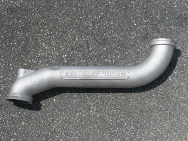
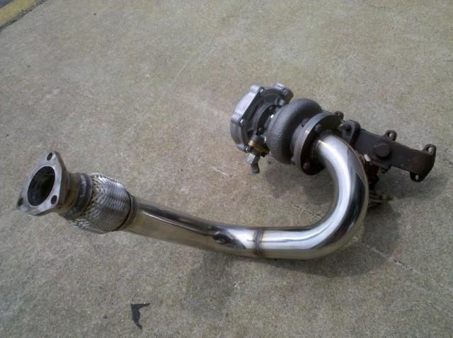
This is most of the Stage I Callaway kit to be installed. The heart of the kit is below.
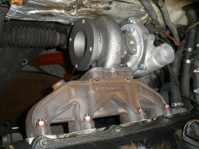
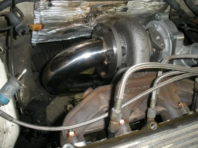
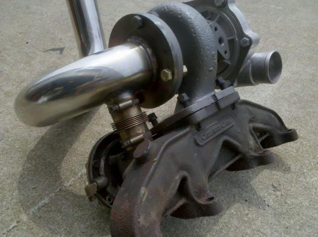
This is a quick shot of a test fit of the turbo to clock it properly. Note the stamp of "Callaway Cars" on the exhaust manifold. In addition, a used (torn) heat shield will protect the brake line from the heat of the turbo, mounted on the firewall.
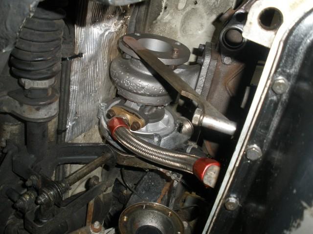
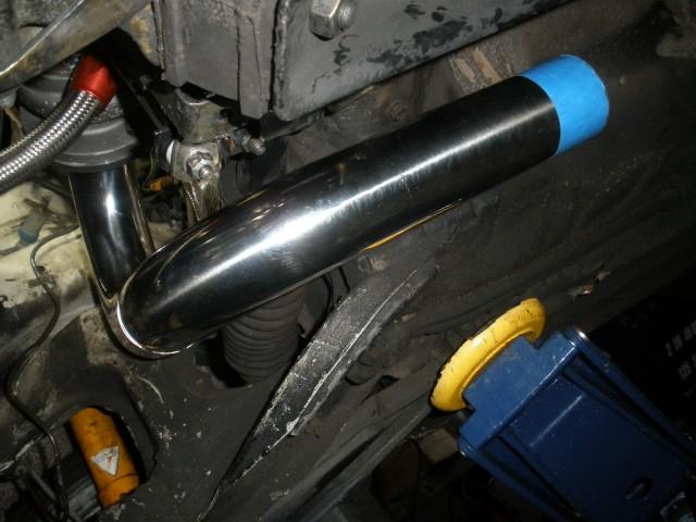
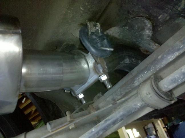
Here is a shot from below to show the oil drain from the turbo to block. Note the bracket to help support the turbo once the header pipe is installed.
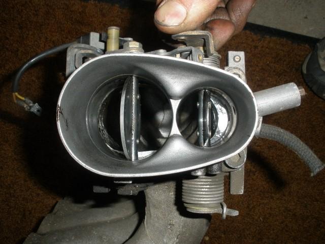
This is what you get when you install an aftermarket, enlarged throttle body onto a A1/Mk1 intake manifold. Note the restriction once the butterflies are opened. This will be taken care of real soon. Stay tuned as Bill is going to work his magic and create a 2.5" downpipe.
Stay tuned.
Thanks,
Jim
5/12/2010
Bill and I have had some time over the past few weekends to clean up a few items and sort out the small stuff. You will be surprised how much time it takes to sort out the small things. I want to take care of anything that might be a weak point down the road.
Below are some pictures from a few weekends ago.
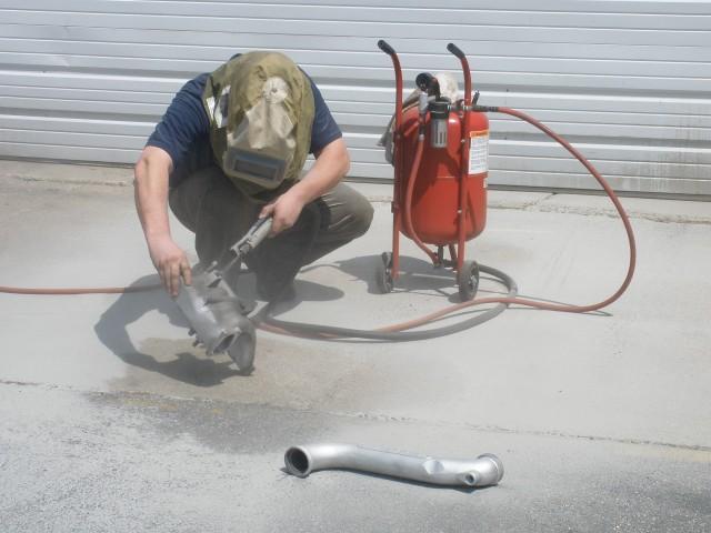
Bill tackled the sandblasting on the Callaway pipe and intake manifold. The end result is worth it.
This came out very nice. No more grease and grime. 
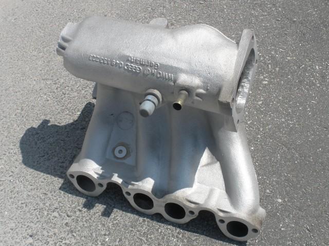
In addition, the intake manifold came out spotless as well. Note the porting at the throttle body end of the manifold.
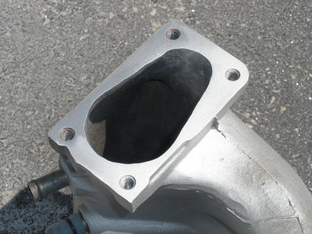
This is a closeup of the porting. A decent amount of aluminum was cleared out to match up with throttle body ports.
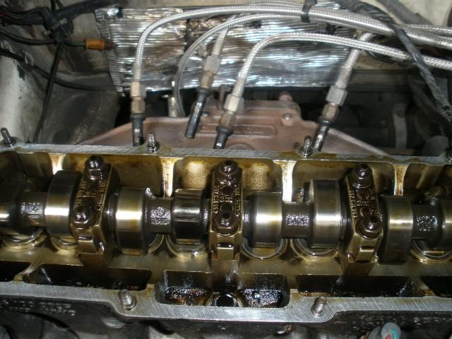
According to the receipts from the previous owner, this should be a 1.6 liter cam. New studs and a rubber valve cover gasket were laid down to cushion a Callaway valve cover.

The motor dropped down a bit to remove the motor mounts on the drivers side and passenger side. Each mount was in great shape so I did not bother replacing them with the HD mounts I had on hand. Lining up the mounts later to get each bolt in is quite the challenge. I am sure some of you know what I am talking about.  At any rate, a new timing belt and tensioner were installed. In addition, all mechanical timing marks were lined up correctly - crank pulley, cam gear, while cyl 1 was up at TDC.
Here is a picture of the relay shaft and the missing bushing at the top of it. This picture is taken from underneath. I used Teflon bushings as replacements. They should hold up well to the heat radiating from the turbo. While each axle was out, each drive flange seal was replaced.
As of now, I am waiting for some G11 coolant and Redline MTL gear oil so we can fill up the engine with new fluids. The next step is to button up the bay and then begin manufacturing the down pipe with some stainless 2.5" stock. We can't replace the passenger side axle, which received two new CV boot kits, until the downpipe is finished and installed.
Jim
5/17/2010
This past Saturday was all about getting a new down pipe made out of stainless steel stock to maintain a 2.5" diameter from the outlet of the turbo all the way to the tail pipe. Bill put his welding and fabrication skills to work :bow:before I could turn on the camera.
Because I had an original downpipe, a jig was made. Don't under estimate the time and effort needed to lay one out as this is the ground work for the new down pipe.
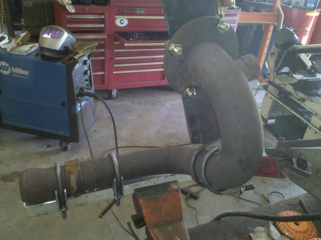
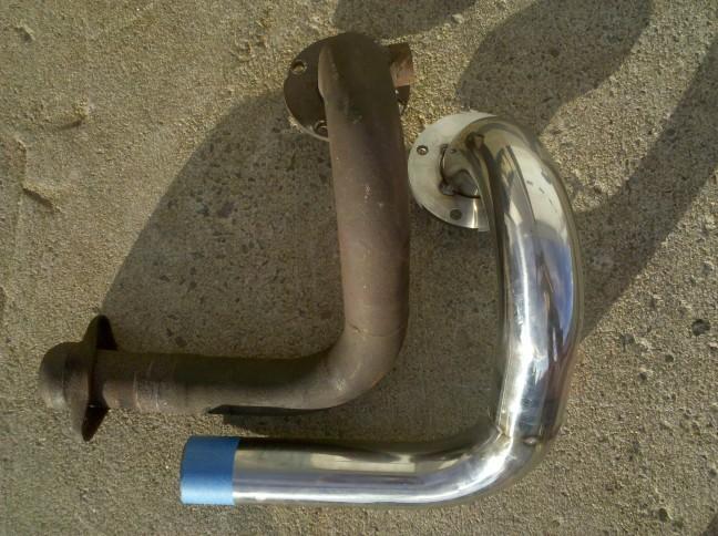
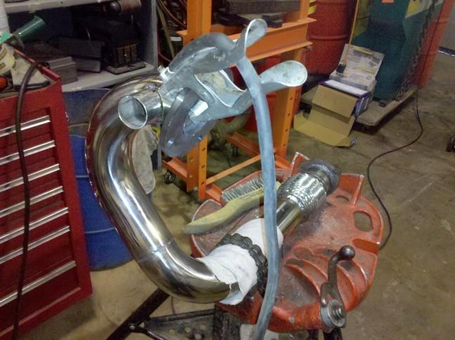
This shows the side by side down pipes together. Note the end of the new stainless down pipe still has not been cut down. Two pieces of stainless 2.5" stock were cut, and tacked to make the what you see here. Bill worked from the top down starting with bolting the flange into the jig. A 180 degree pipe was cut to make the top from the flange (picture the letter "U") down to the just above the J-bend into the horizontal axis. The key is to measure twice, cut once! Note the 4" flex braid (w/internal bellows) on the left hand side of the bench. This will be welded on the end of the down pipe. A three bolt flange will finish it off at a later date when we call it a finished product.
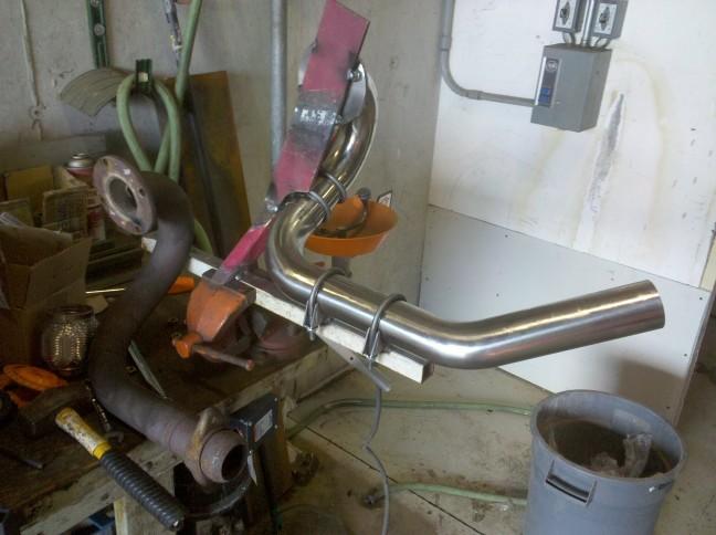
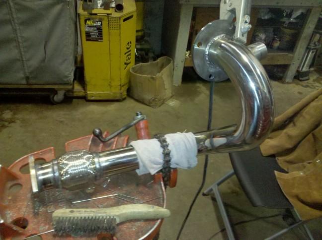
Another comparison of the two. Part of the quality control process requires a test fit in the actual car. You can see the TIG tack welds at the flange and at the 90 degree bend.
Here we test fitted the down pipe to ensure proper clearance in the engine bay. We are pondering the option not to dump the wastegate gases that are expended back into the down pipe. We have R&D looking into that over a cup of coffee. 
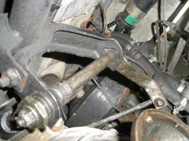
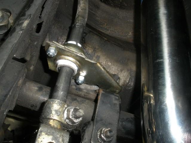
The proper clearance is especially key down here as it approaches and enters the tunnel. We have about .5" of clearance toward the closest object which is the bracket for the steering rack. Because there is minimal shifting of the motor from east to west, all should be good unless I am doing a track day or autocrossing.
The input rod bushing was replaced with this teflon (white) unit from MissingLinkz. This tightened up the shifter feel significantly.
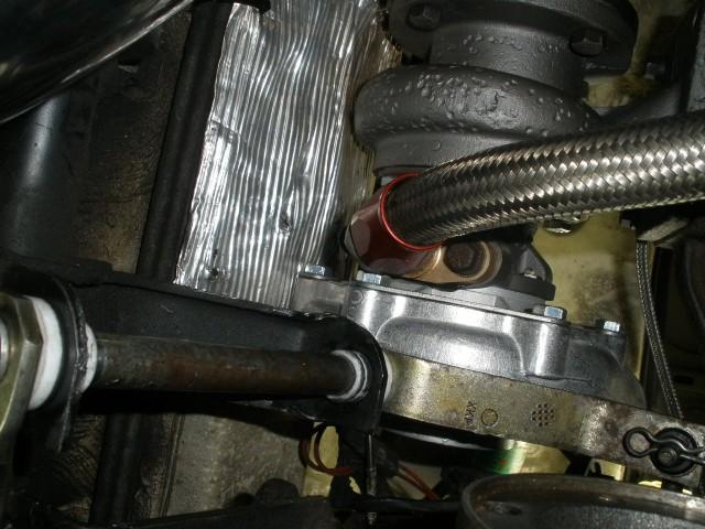
Here is a close up of other previously mentioned replaced bushings. Again, MissingLinkz came through with these. Note the white bushings at the top and bottom of the relay shaft.
To make the kit complete under the hood, a Callaway Valve cover is a must in my own humble opinion. This one has already had some rehab but will do for now until I kind find one in better condition.
In summary, it is coming together. A few more small bits are on the way. The down pipe will receive the final welding this coming weekend to call it a finished product. Then we'll hang the Techtonics Tuning exhaust and see what needs to be modified to make up for the length of a catalytic converter.
5/25/2010
Bill and I had a small window of opportunity to remove the Gillet Power Sound exhaust system from the Gti yesterday and test fit the 2.5" Techtonics system. I felt pretty bad about making one cut before the rear beam to remove it. The exhaust was pretty quiet and has a nice gloss tip on it. It can easily be welded back together to offer a few more years of service in another project down the road.
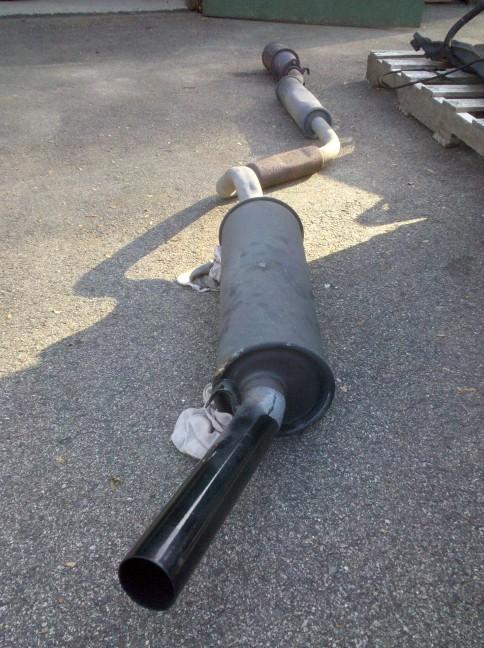
This is the ultra rare Gillet Power Sound exhaust that was removed. It was on the car since 1986. It was installed at New Dimensions in California.
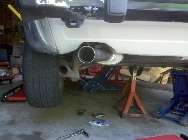
In with the new 2.5" Techtonics Stainless system with a Borla muffler. This shows the tail pipe exiting the rear valence. I can't wait to hear this thing rip.
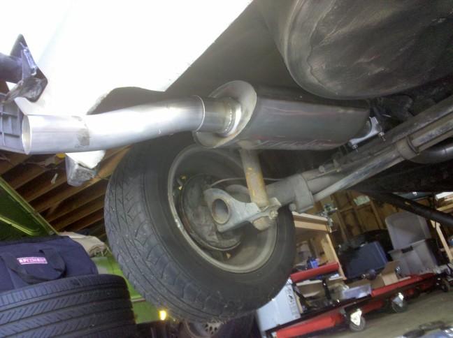
This shows the close up of the Borla muffler and tailpipe as we are just test fitting for now. Oddly, I used to used to have the Borla muffler that came off this car back in 1986. It had a dual outlet tail pipe. I gave it away a few years ago. It made it's way onto a Rabbit Convertable from New Hampshire. I saw it installed at Dust Off 2009 last May. It was nice to see that it got recycled for good use.
Look closely above the rear trailing arm and you will see an ultra rare bar bolted in. The brand name back in the 1980's was Pulsar. You will see the name referenced for various aftermarket parts in the Water Cooled Volkswagen Performance Handbook by Greg Raven. In addition, despite the test-fit instance, there should be plenty of clearance for the 2.5" pipe to clear the trailing arm (rear beam) and also not touch the heat shield for the gas tank. We may need to "tap" a gas tank strap just a touch but we'll see once we have the exhaust connected and hanging. Of course this trailing arm is hanging a bit with the car on stands. It may travel toward the car just a touch once back on the wheels. Keep that in mind as you hang and test fit your exhaust system of this diameter.
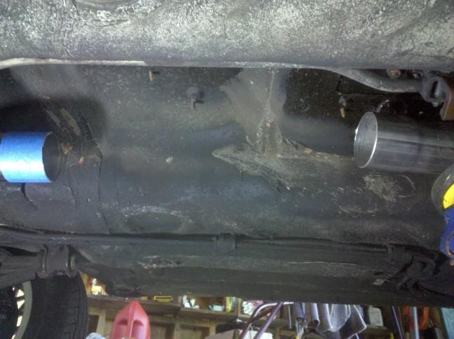
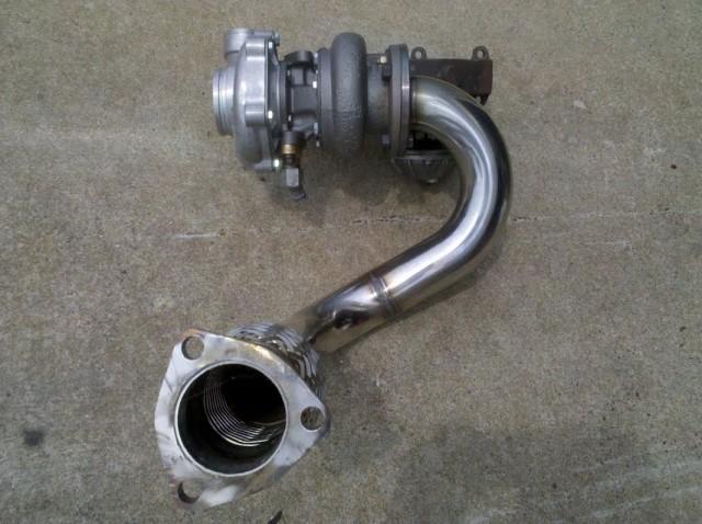
This the gap (about 16") between the exhaust and the down pipe from the turbo. We are awaiting a three bolt flange to arrive in the mail from Mandrel Bending Solutions in Maryland. A four inch stainless steel flex coupling will be welded to the end of the down pipe.
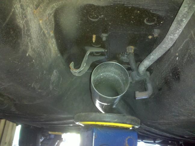
This is just a test fit but as the exhaust sits in the tunnel, there is plenty of clearance at the moment. The question is if we can retain the hanger from the body. We shall see.
6/17/2010
A couple of pictures from a few weeks ago. It is 95% finished. I am hoping that Bill and I can squeeze in some time tomorrow afternoon. After this is done, it should be just nuts and bolts going forward.
Thanks,
Jim
7/2/2010
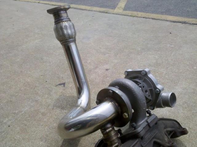
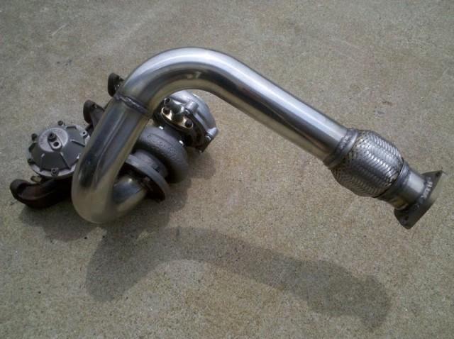
Bill finished up the down pipe this past weekend. It came out very well and everything bolts right up in the car and to the Techtonics exhaust. As for the overall status, we are very close to turning the key to hear this this roar. I had to order a few small bits such as a 3.25" silicone coupling. We should get some time to finish up the wrenching over the holiday weekend. My fingers are crossed. 
Jim
7/6/2010
It is running. It fired right up on the 1st try tonight. Timing is set to TDC. Need to install the boost gauge and tidy up things like the water injection. Road test slated for next weekend. I am so happy. I will add pictures in 24 hrs. Meanwhile, here she is idling at 1K rpm.
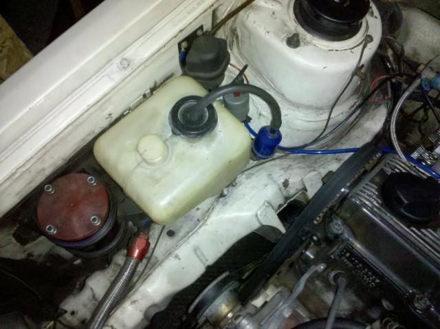
Below is a shot of the engine bay. It needs a good cleaning down the road, but it runs which is what counts, right?  Pardon the timing light leads.
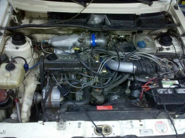
The Callaway Valve cover really compliments the engine bay to not only make the kit complete but unique. This one will need reconditioning.
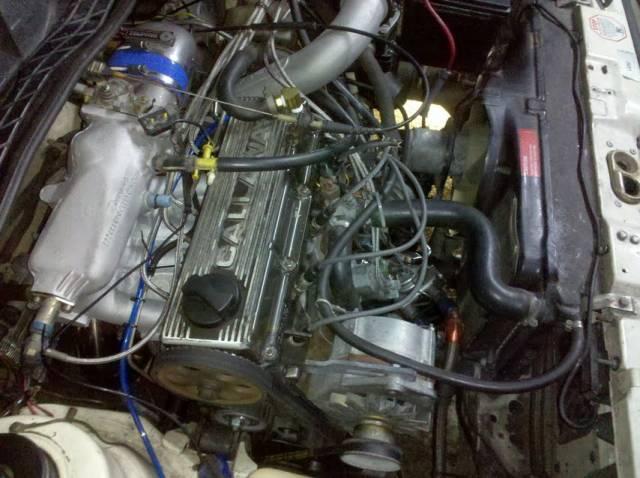
Isolated away from all of the action is a Hobbs switch for the water injection. Also, you can see one of two Mecca Oil filter housings (red cover) that have been under the hood since 1984.
The next order of business includes a boost gauge install. I purchased VDO cockpit series unit that has been obsolete for a few years. It only goes up to 15 PSI which is what I wanted for this mild but wild package. 
Thanks,
Jim
7/12/2010
I have put about 30 easy miles on it and put in the garage to close an eventful weekend. The passenger side drive flange popped out 2 miles from the house on Saturday. My bunny and I got a flatbed ride home.
Bill saved my bacon on Sunday helping me get that nasty clip back on that holds the drive flange. They absolutely suck unless you have the transmission on a work bench. I did not have time for the boost gauge install so not sure what the car is pulling. It does feel good. Beyond the gauge, I need to sort out a few things before this passes quality control and is signed off for the race track.
Jim
7/26/2010
A few more small steps this weekend. I removed the aftermarket oil pan baffle/scraper in order to expedite the return oil from the turbo into the pan. It is a pretty slick item and amazing work from whoever made the time to make it in the 80's. Dropping an oil pan full of oil is not fun but happy to report my friend Patrick and I did not spill much. I should have left it out when I had the chance last month.
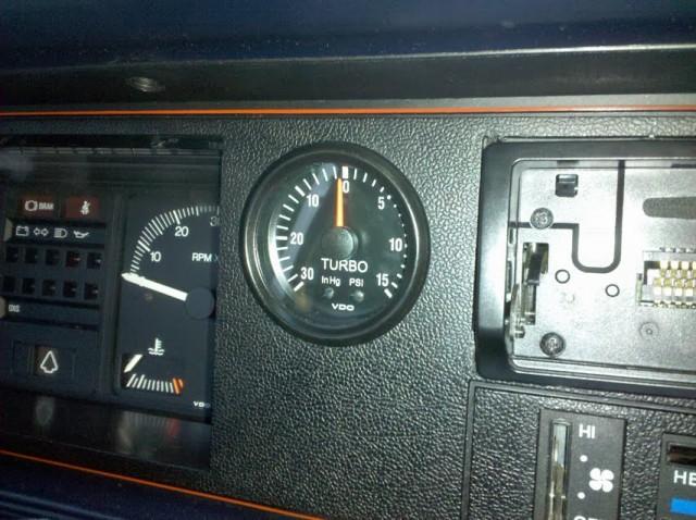
I reclocked the turbo about 15 degrees to get another 1/2" of clearance at the fire wall. In addition, I got my new NLA VDO boost gauge installed. I had to buy a pilot drill bit and 2" hole saw tool from Home Depot. I used that to cut a 51mm hold in the dash bezel. A little dremmel sander work was used for the extra 1mm needed to fit the gauge. I had a NewSouth peformance boost gauge install kit on hand to handle the nylon tubing and brass fitting at the end of the gauge.
Here is the finished install. I wanted the classic look of the VDO boost gauge with the zero in the 12 o'clock position and limit the boost scale up to 15lbs. I was fortunate to find this gauge as VDO made it obsolete several years ago in favor of 25lbs. This one came off the shelf from Hollywood California.
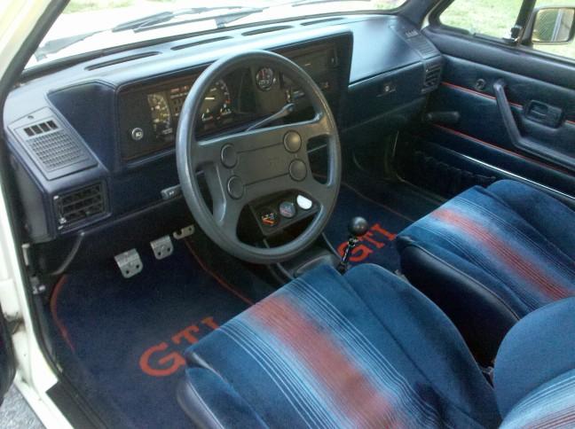
Here is a happy interior complete with boost gauge. Notice the old school Hurst Shifter and Sparco pedal covers.
I took the car out for a test spin and was happy to see 7lbs of boost. It is one thing to feel the boost but it is reassuring to see it on the gauge.
I have a few things to sort out but overall like where this is going. I still need to sort out the water injection in the future.
On a side note, a Callaway powered Corvette drove past me tonight. Little did he know that I too was pulling some heat under the hood.
Thanks,
Jim