You must be logged in to rate content!
134 minute(s) of a 278 minute read
12-27-2020
Compliments of sdezego @ VWVortex.com
September 03, 2006
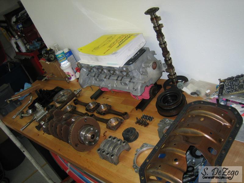
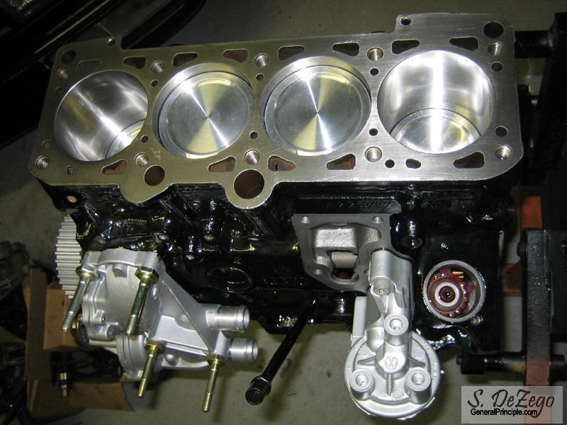
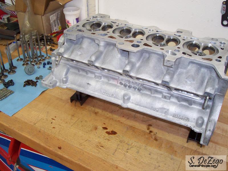
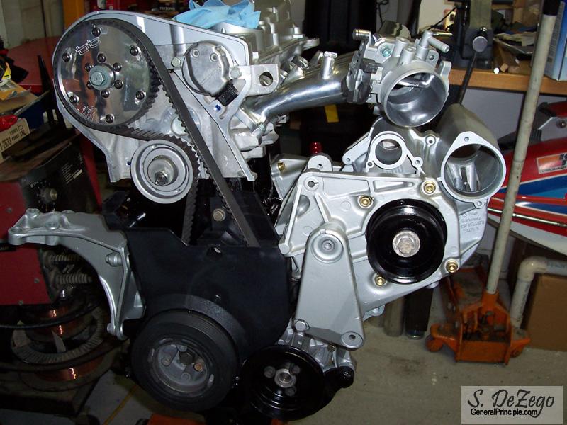
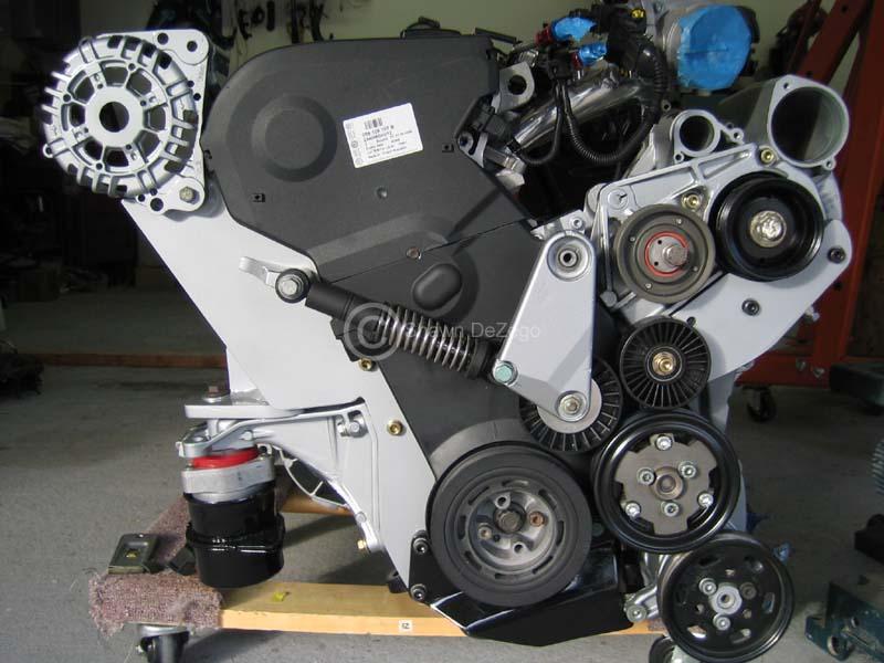
Assembly has finally begun.
Since my Interior Project is now complete -> http://forums.vwvortex.com/zerothread?id=2772227, I finally had some time to start assembly of my Hybrid 2L-20v G60.
Planning, parts gathering, prototyping and machine work has been going on for about the last 6 months, but Assembly finally started yesterday. And progress has been great with no snags thus far.
Here is the plan for those who don't frequent the G60 Forum:
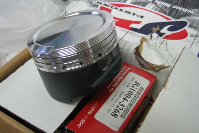
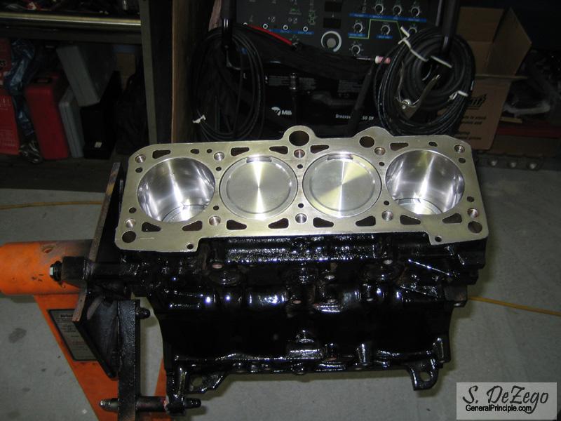
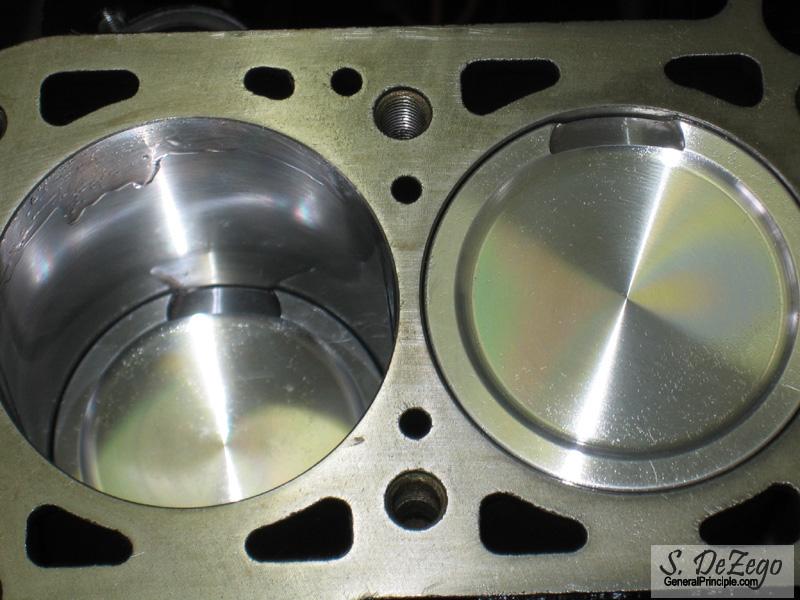
- 2L ABA Bored to 83mm with Custom JE Forged Pistons (9.25:1)
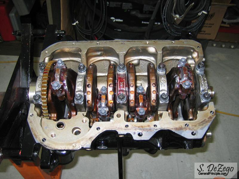
- ABA OBDI block with Forged Internals, ARP hardware, Resized and Shot peened rods
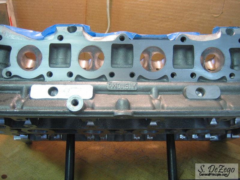
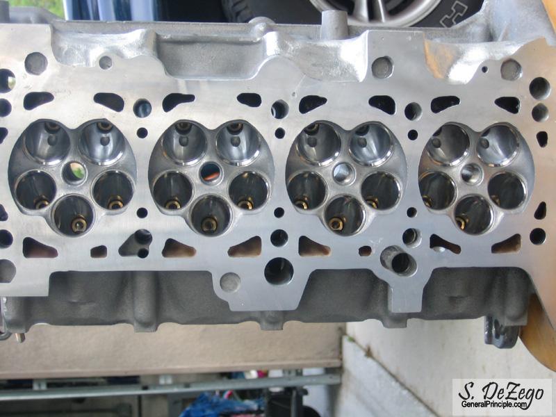
- AEB 20v Head (Large Port)
- Custom Modified SuperSprint SS Mk2 16v Header re-Flanged for 20V
- Light PnP and gasket matching
- Stage IV G60 , Pulley size TBD to match higer revs
- MsnS-e
- FMIC Precision Core under Dietrich RS
- Euro AGU Intake
- some other stuff
1.) Before I begin, let's get some semantics out of the way. This project is not about "the biggest numbers on the tex" so please don't talk about Big Turbos "BTs" here.
2.) If you have any basic questions on 20v Hybrids, please visit this thread -> http://forums.vwvortex.com/showthread.php?1674618. Al ot of details on my research and specifics are in there.
3.) Although I am not the first 2020 by far, my setup will definitely be unique and will be full trim with A/C.
3.) pic centric thread as usual.
DisAssembly of donors
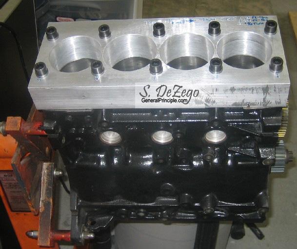
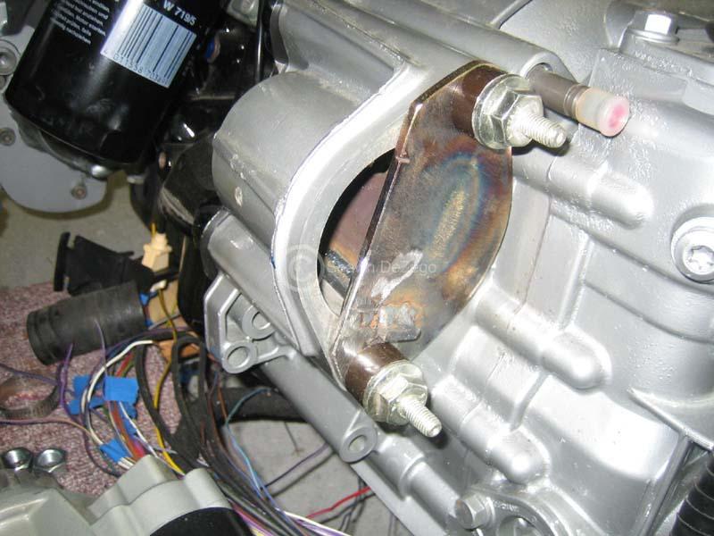
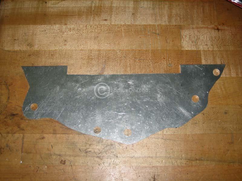
Since no machine shop around here had a Torque plate to bore my block with, I decided to make my own
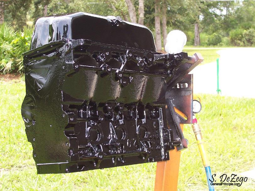
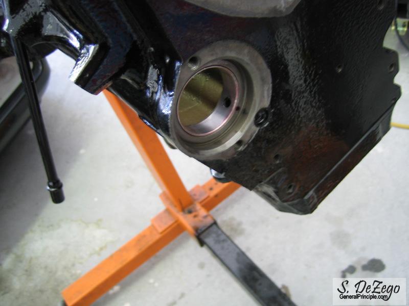
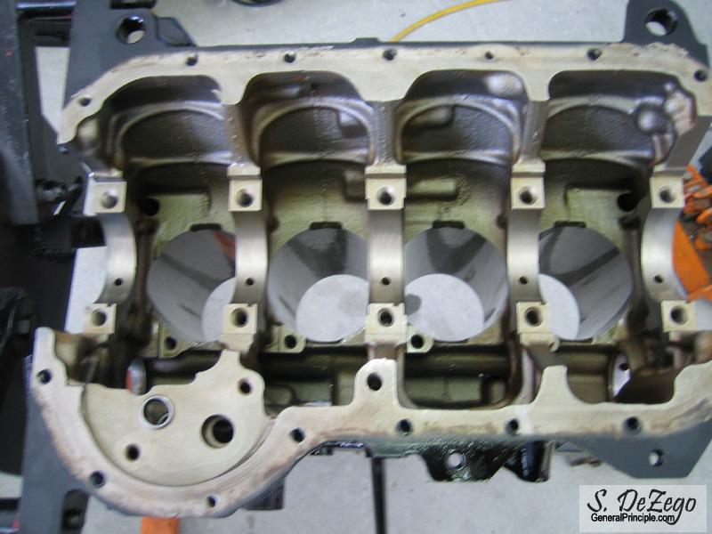
Painted Block
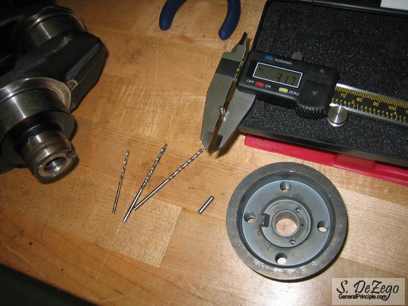
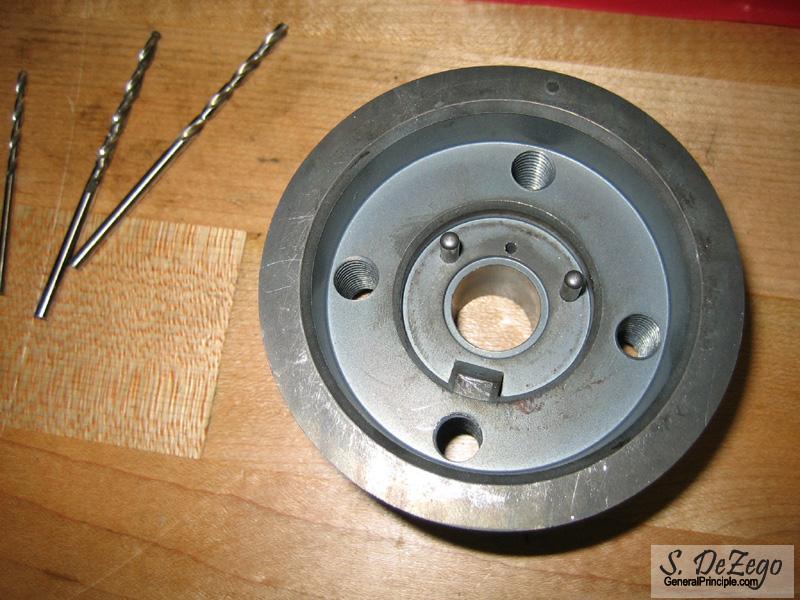
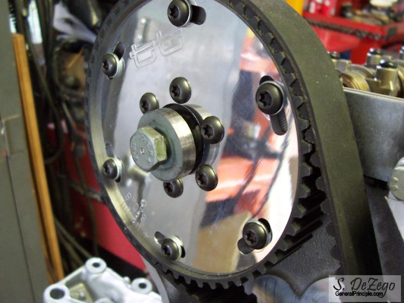
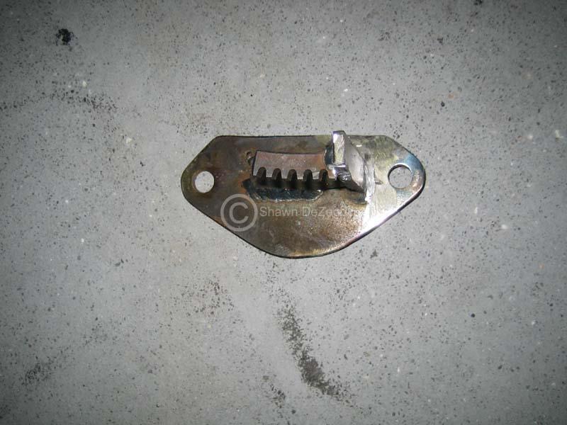
Pinning the Crank Pulley
ABA Intermediate Shaft Modification for distributer using AWP 52T Cam Gear (initially)
After Checking the IM Shaft bearings, I realized that the machine shop honed them to big... I shoudl have just done them myself to begin with.
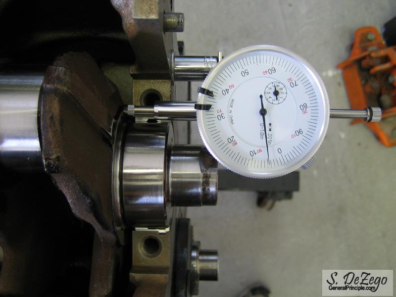
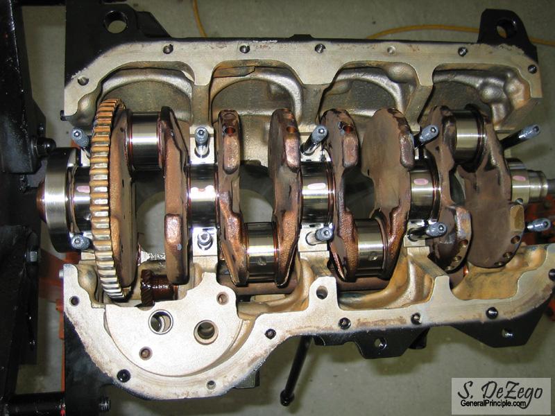
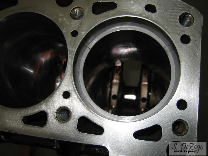
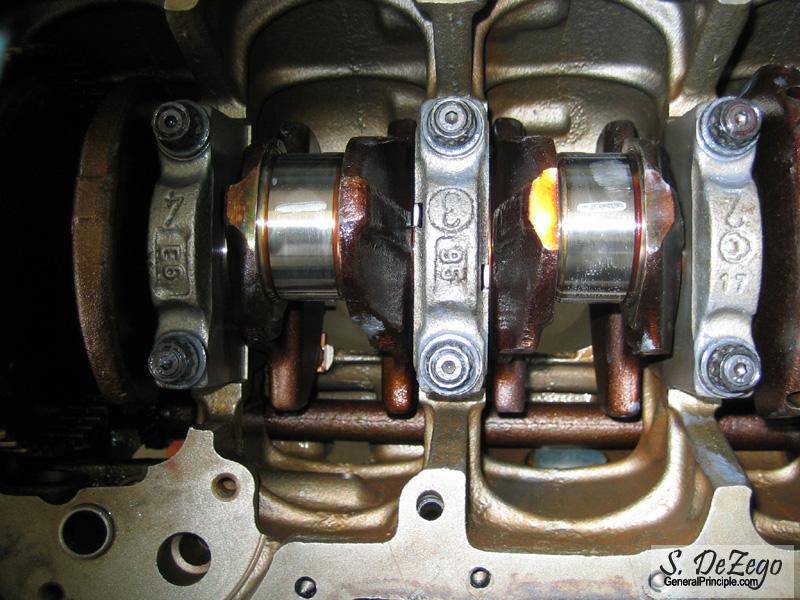
Checking the Crank Shaft Axial Play
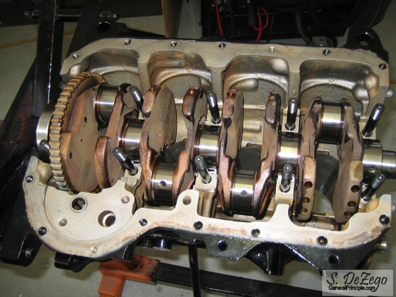
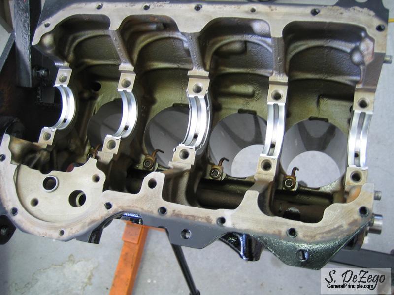
Plastigage'ing the Mains. I always check..
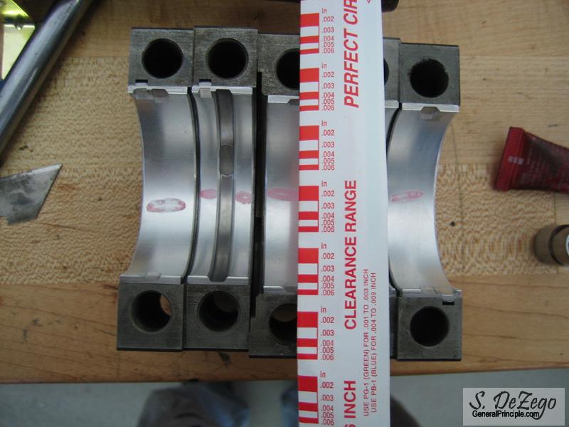
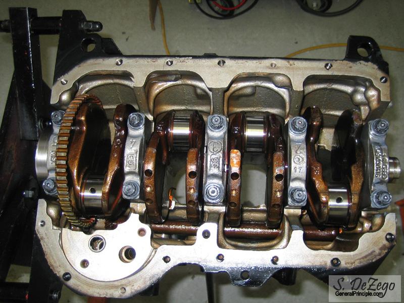
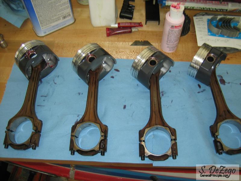
Checking the Rods with Plastigage
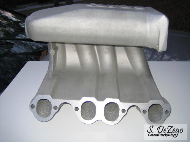
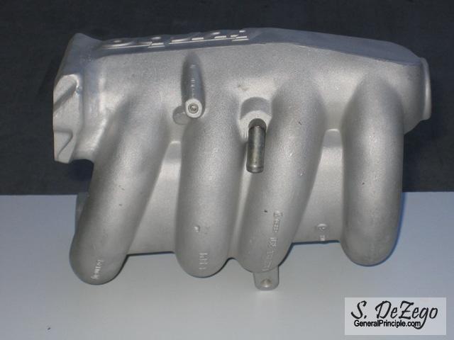
Forgot to add my original Mock-up. Shown is the Euro Large Port Intake from the AGU Golf.
I am going to Run Dizzy Initially, but will then go to either Coil pack using the ABA 60-2 took trigger or may even go COP.
September 04, 2006
An excellent question really. Especially, since you need to do a special board tweak for MSnS to accommodate VW's Dist Hall Sensor.
The orig plan was to Build MS, Config and install it on my existing G60 on Dist, get it tuned and run it for a while. Basically, get it all ready to throw on the new motor and then have to just tweak the maps rather than work out any bugs on the new motor. Still the plan actually, but since I finished the MS build a few months ago and the motor is well under way, the idea is making less sense.
Also, I already had all of the stuff for ABA Dist and the only thing I needed was the Cam gear and a 20 minute IM Shaft mod.
The past week or so, I have been seriously rethinking this though and may go 60-2 Coil pack right off. I may even setup a 60-2 on my current PG to get it all ready. I go back and forth.
Thanks! You will definitely see it. Been driving it alot lately and enjoying it. Realistically, the motor will not go in for a few months as I am not rushing it. LOTS of stuff to work out between now and then.
Among other things, I am thinking about the gearbox as well. Peloquin at the bare min, but need to sell some more parts to pay for that. I have also been thinking about an 02M lately That is just a matter of money, not effort.
Shawn
September 05, 2006
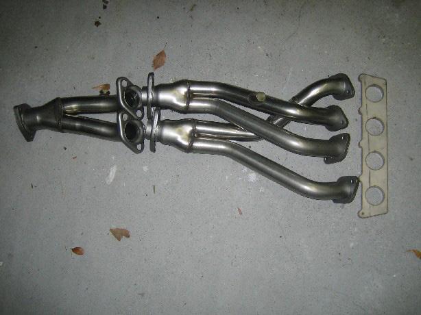
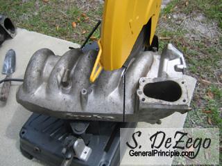
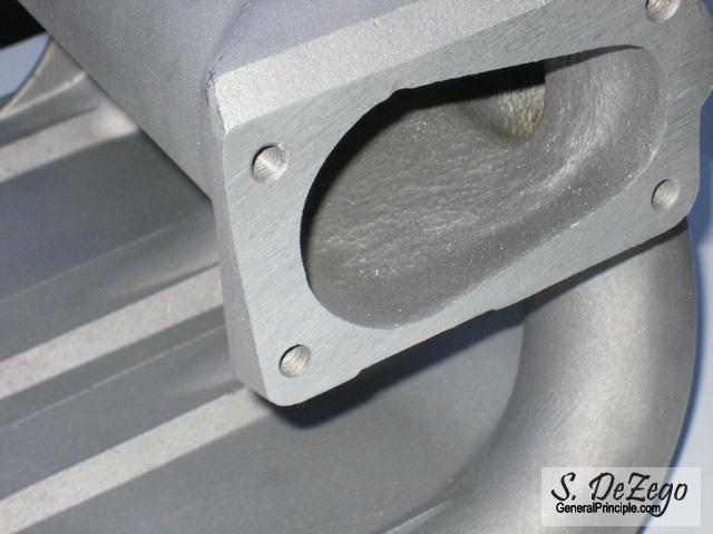
Here is what I will be using to take care of the waste.
SuperSprint 16V mk2 header modified with a 20v Flange and some gentle persuasion to reorient the headers.
September 15, 2006
Been out of town and busy, so no major progress except for spending more money and more circular decisions regarding ignition.
I have some 16V IM Shaft parts coming Tues, so I will make a Final decision on Dist vs Coil Pack (or COP). If you want to know what I think was the final clincher, you may laugh. I will be running the Timing belt guards and the lower AEB guard will not fit on the 52T IM Shaft Gear for Distrubuter (obviously since the AEB uses a 43T gear like the 9a). It is just one of those things you don't think of until you go to do it. Also, the 43T gear will turn the Oil pump faster, which can't be a bad thing I just want to take the ABA and 9a oil pumps apart to compare and make sure this is nothing I am missing (other than the forked vs splined shaft). I am almost certain the gears are the same size, but want to verify reliefs and such.
I did get my Vr Lenses and Bezels installed on my ECodes though. All I can say is Flush! The G60 Ecode gaps and steps from Vr grill to fenders really annoyed me. I also have a set of Vr Fogs coming for the RS Front that will house the Precision FMIC.
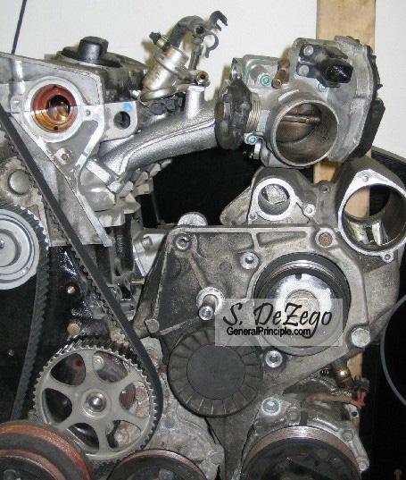
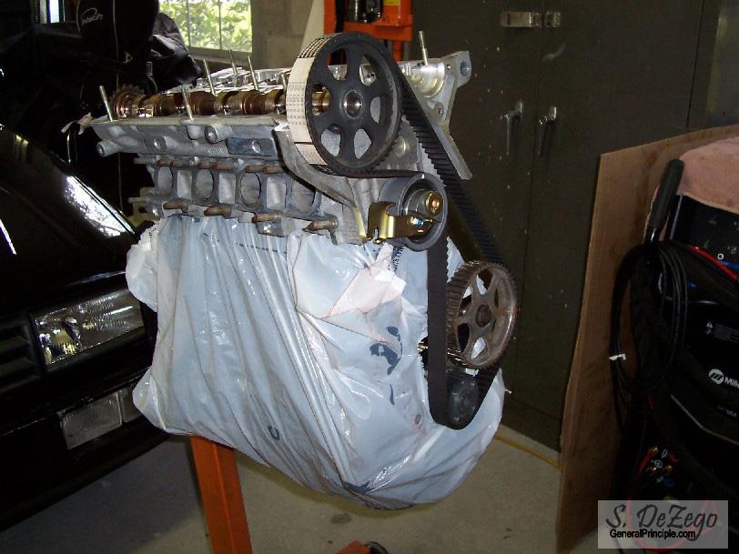
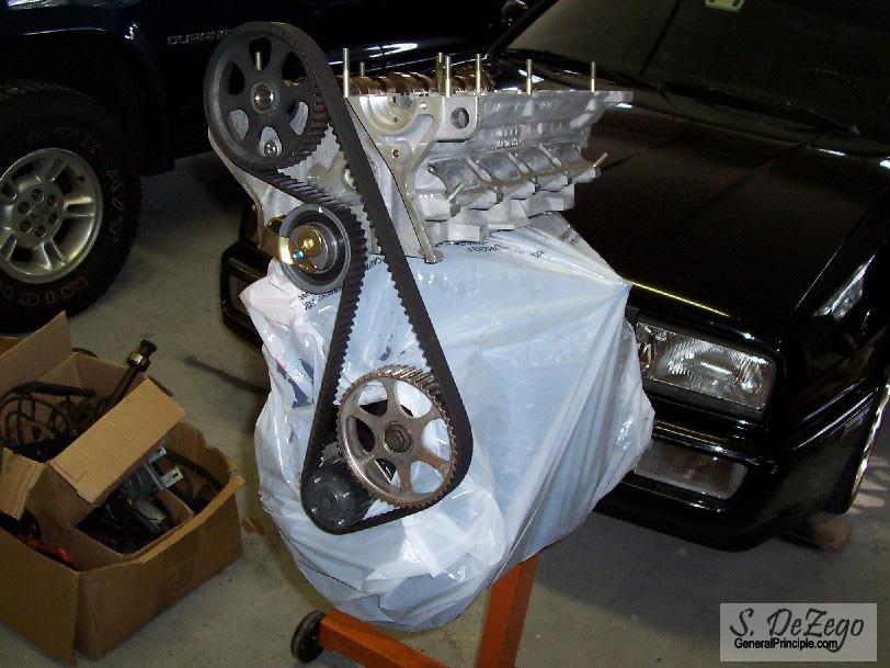
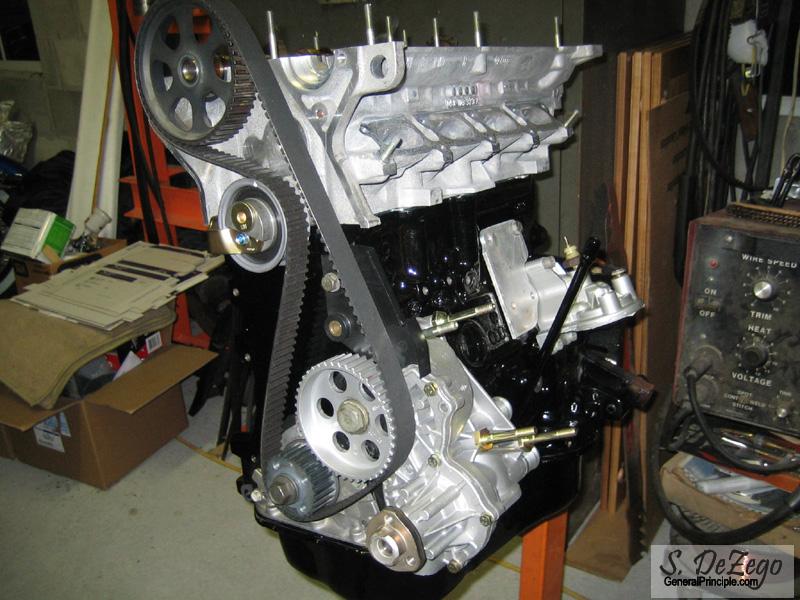
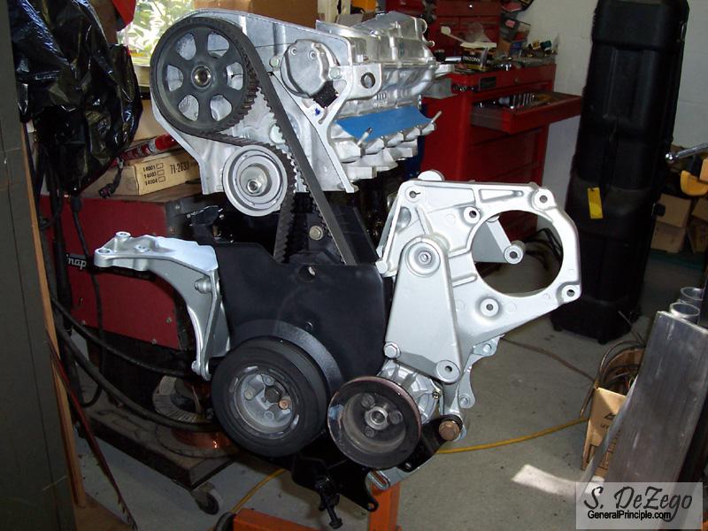
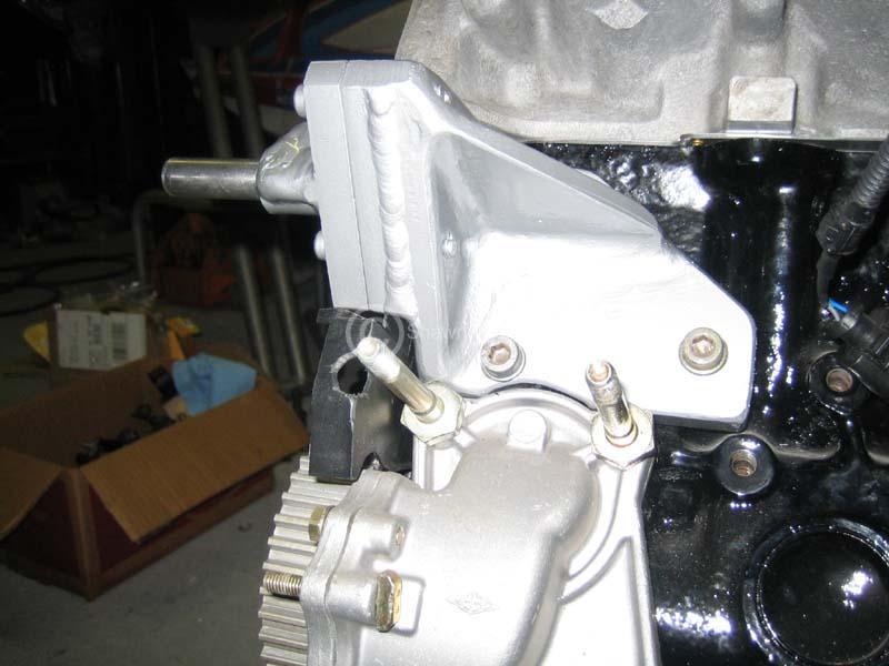
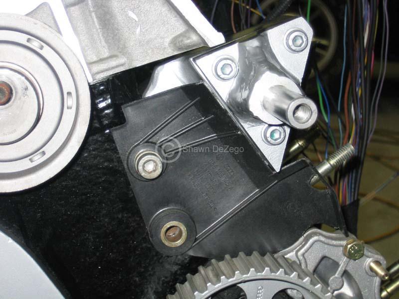
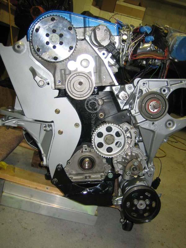
Mock pic of the head and belt on (now all subject to change). I also, did not make the tensioner mod yet to affix it (since the stock 20v uses the hydro damper and relay roller).
September 21, 2006
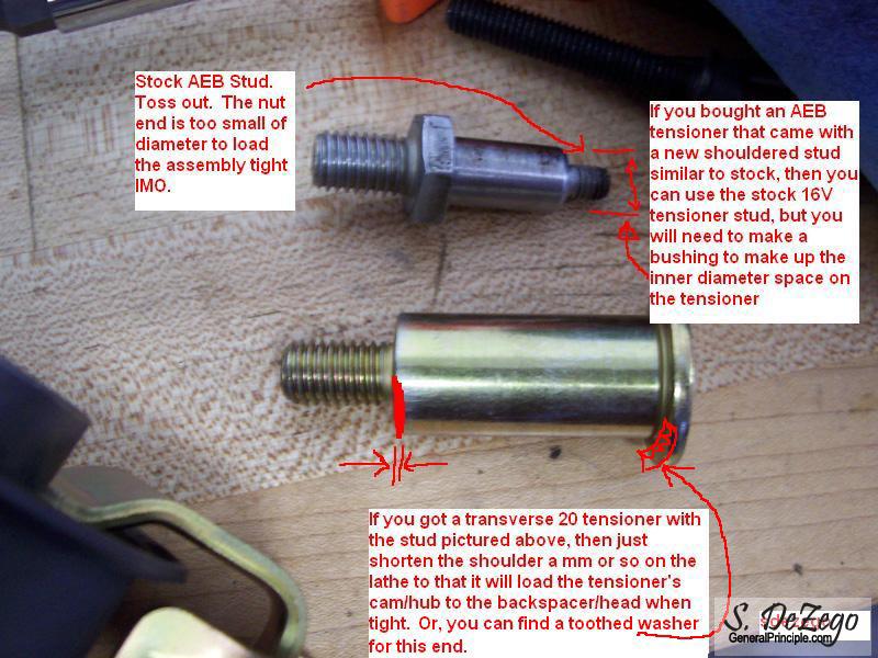
I had a few questions about how I was going to modify the 20v Tensioner, so here is my off the cuff ideas.
1st - If you are not running a Dist and plan on running the 16v/aeb IM shaft 43T gear, then you can simply use the 16v "fixed" type tensioner with the 157T custom belt and call it a day. No need to read on in this post.
If you are running Dist (Which I was going to), you have to run the only available "correct Tooth belt" at 158T (159T would be perfect) which will not fit with the 16V tensioner. You must use the 20V variant which allows you to use the 158T belt.
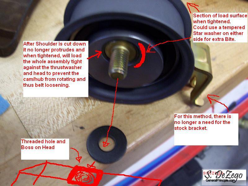
Here are two ideas that I had for mod'ing the 20V tensioner to make it "Fixed" instead of the hydro self-adjusting. Even though I am not running dist, I may still use the 20v type pictured and "affix it" as shown.
Option #1

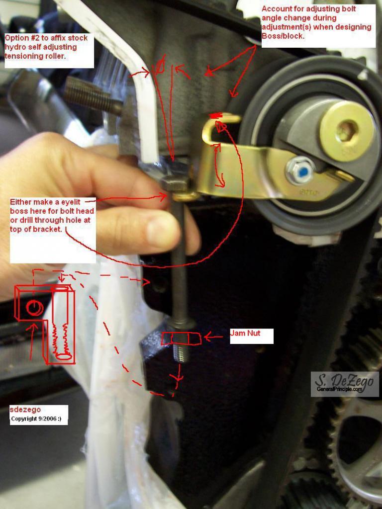
Option #2
October 11, 2006
sorry, I have been very busy here on the text reading your updates and googling, thus no time to work on mine
Actually I have made some progress of sorts. I ordered a crap load of misc parts, factory bolts, studs, elec connectors etc that should be here any day.
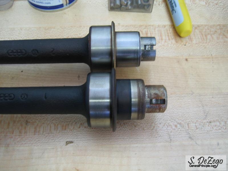
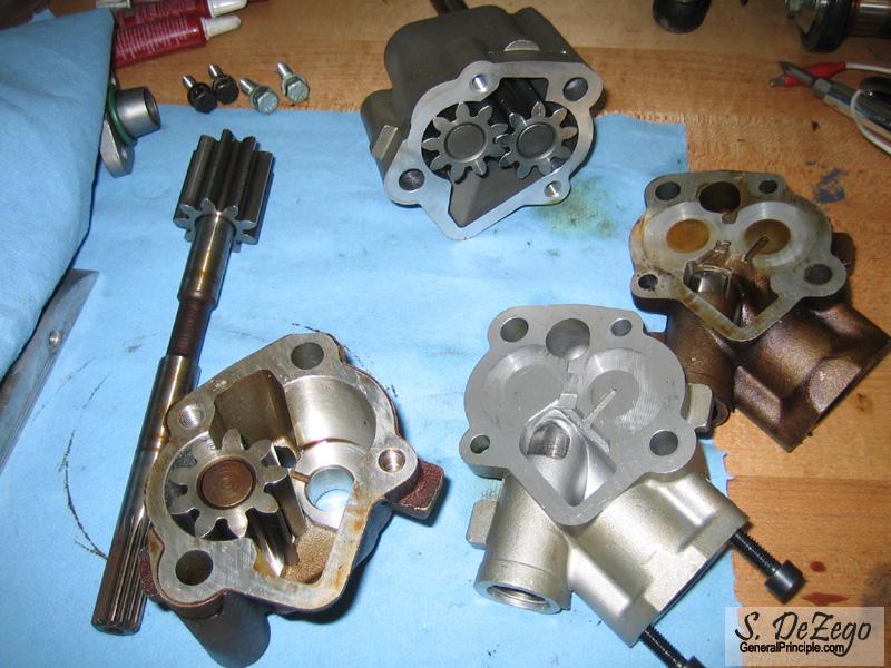
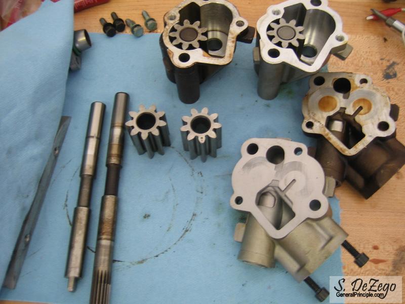
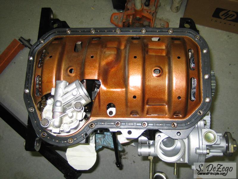
In addition, I took the 9a and ABA oil pumps apart to compare the internals, and as suspected, everything is interchangeable. The only difference is the Splined drive shaft on the 9a as opposed to the Forked one on the ABA. I will show some pics just for the heck of it.
So the definite plan "now" is to run the 60-2 trigger on MSnS-e as opposed to Dist. So, I am going to swap out the Modified ABA IM shaft and Cog for the 9a. Didn't put the oil pump in or pan on yet, so this is no biggie.
I have also been trying to decipher whether the 60-2 pickup I have from the ABA that I have will play nicely with MS. Seems to be some conflicting info out there and I don't own a scope.
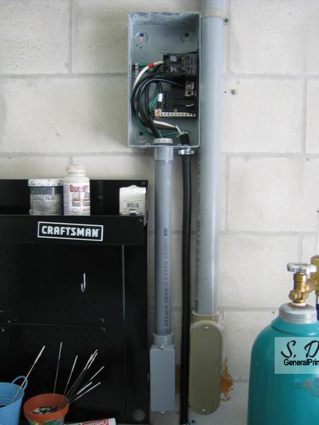
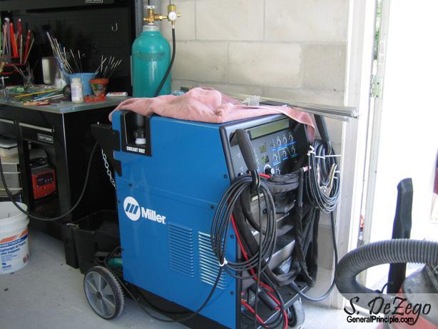
I have also been doing some wiring or sorts Hooking up a new Tig in my garage and honing my skills. Lots of stuff to put this to good use on!
Shawn
October 11, 2006
You have pictured an internal Waterpump and a short block and therfore there are numerous OEM VW belts. For the ABA (Tall Block) Running Dist, there is no belt that will fit using the 16V tensioner (OEM or custom cut). 159T would be perfect and would allow the use of the 16V tensioner, but there is no such belt. So, you must use a 158T which requires the use of the modified 20v tensioner
Edit: No Belt with the Correct Tooth Profile. Nice setup BTW!
S
October 26, 2006
very slow progress. Too many other projects and such, but should have the rest of the bottom end buttoned up tonight.
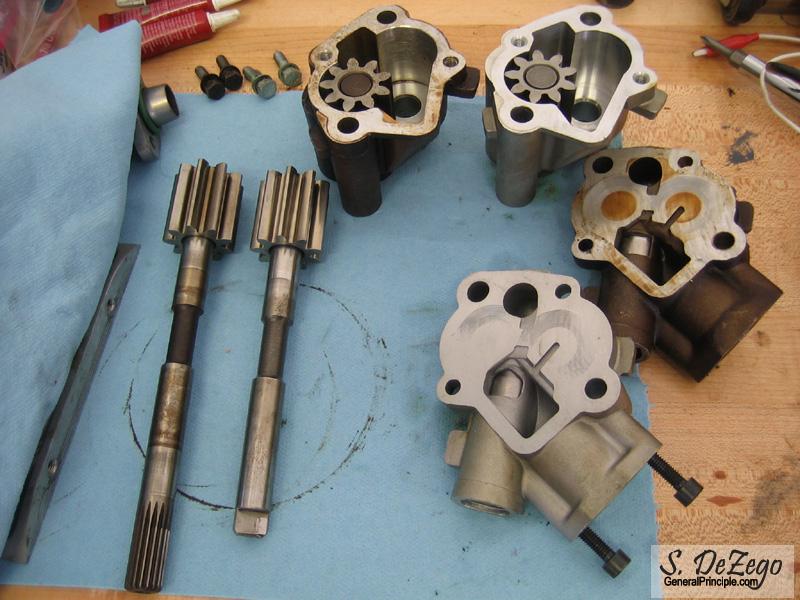
in the mean time here are some pic of the Oil Pump.
In case anyone is planning on changing directions Mid stream as I did (Dist vs COP or WS) or in case you just enjoy saving a few $s, here is a tip.
If you plan on running the 16v Oil pump drive Gear and dist block off setup you can swap the Shafts from an old 9a oil Pump into the much less expensive ABA oil pump. I don't think the 16v PL has the recess notch on the Oil pump shaft becuase it does not have clearance issues as the 2Liters do, but irregardless.
Pics tell the story. oh, yea, you MUST have a press!
November 04, 2006
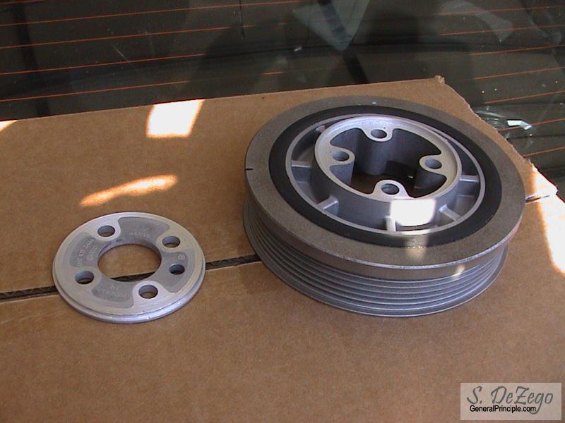
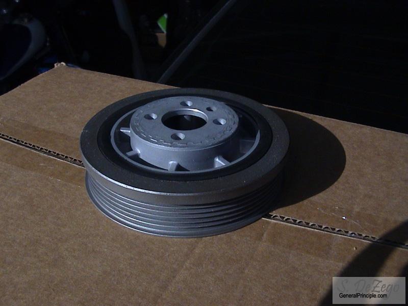
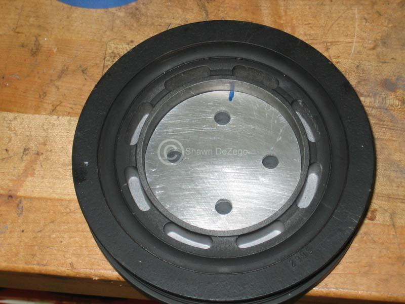
Another week out of town on business, but made some progress in the machine shop today. Here is my way of modifying the ABA serp pulley for the wider 16v/20v belt.
- Total cut was ~5.8mm
- .001" press fit
- perfectly eccentric and uses stock crank centering
- perfectly balanced
December 10, 2006
Yea, that was the only one I had at the time from a spare motor. Since that pic I did get up an OBD1 ABA TB
I really haven't finalized the routing design just yet, but I have a plan and a fall back plan.
My Main Goal is to keep a nice compressed flow out of the charger down into the FMIC (Drivers side) and then from the FMIC P/S up into the TB.
Having the air filter on the PS might be a bit tricky to route and probably impossible with the stock air box, but running the Eurosport Coolflow and a K&N looks doable.
I really want to go back to the stock air box, so I may run the air box on the Driver's side where the battery is and trunkmount the batt.
I also plan on making the charger bypass mechanical from the stock G60 butterfly/Bypass welded onto a pipe just before the TB.
Shawn
January 02, 2007
In the process of doing the head now, just too many things going on at once. I finally had a chance to finish the install of Megaaquirt on my current setup and am in the process of tuning. Fired right up and had it idling perfectly rock steady with 42# injectors @ 3 Bar in about 5 minutes ...needless to say it did not idle like this with Digi.
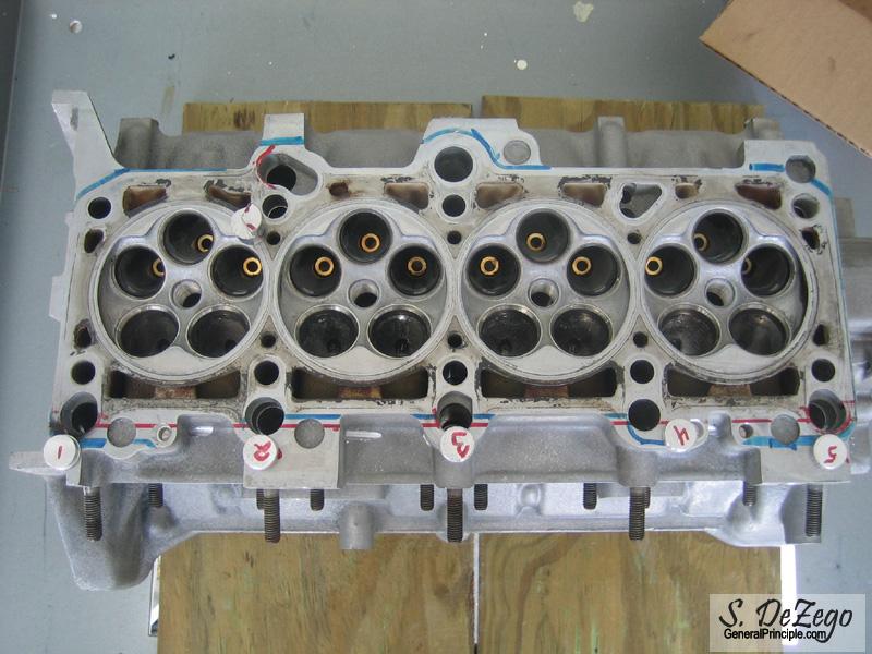
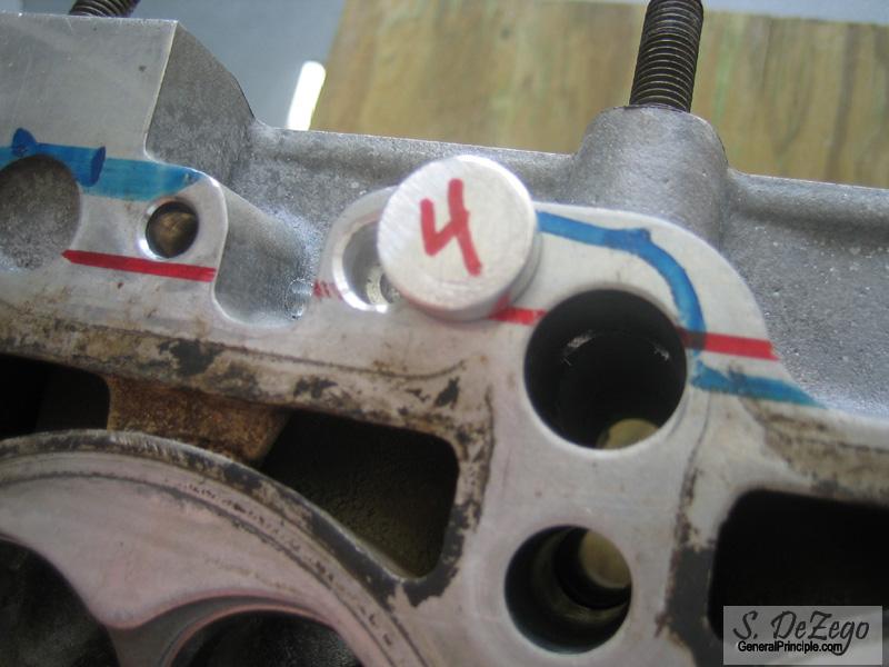
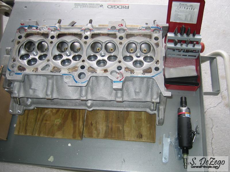
Anyway, here is what I am working on with the head and should have some more pics in the next few days.
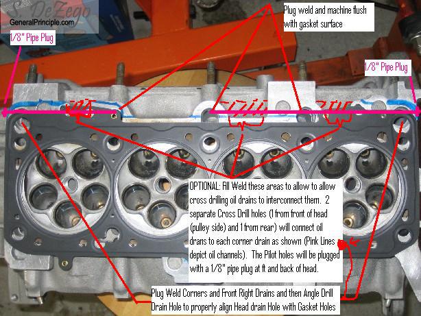
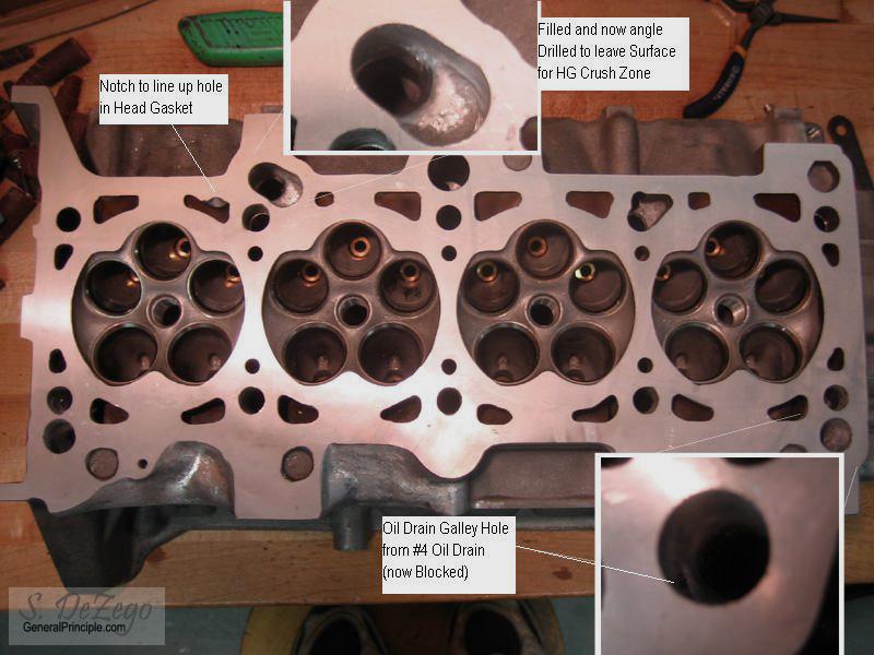
I ordered up some T6 AL Rod(s) and I am going to cut some short discs and knock into the head drain holes and then plug weld flush with the head's gasket surface. The corner holes, as well as the right front drain, will be angle drilled from the drain holes in the gasket to the drain holes in the head. This will align the crush surfaces on the gasket properly with the head.
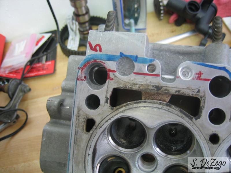
This next step is really what I consider an optional one, but since I am already welding on the head, it is not much more work. I am going to interconnect the 4 rear oil drains via oil galleys. This is to prevent any oil pooling near the exhaust valve guide seals from plugging the 3 center oil drains. 1 will be connected to the rear corner and 2 will be connected to the front corner. This requires filling the areas shown below hatched in red and then cross drilling 2 galley holes (one from the front of the head and one from the rear) to interconnect the oil drains. These do not need to be big. A 1/8" pipe plug at the front and back of the head will then plug these pilot holes (just like the factory did for the lifter Oil Galleys)
January 08, 2007
Update: I didn't get to finish the welding on the head yet, but did make progress of sorts. Tonight, I logged 25 miles on the MsnS setup that I built up for this motor. Had a snafu on the first run the other day but got it sorted. I still need to fine tune, but it runs absolutely amazing thus far
S
January 10, 2007
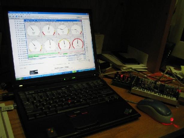
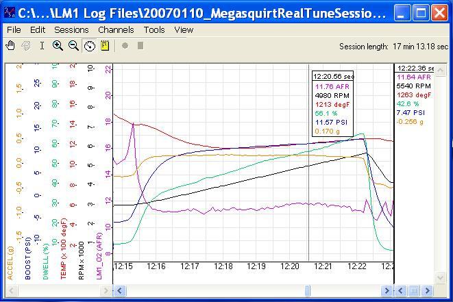
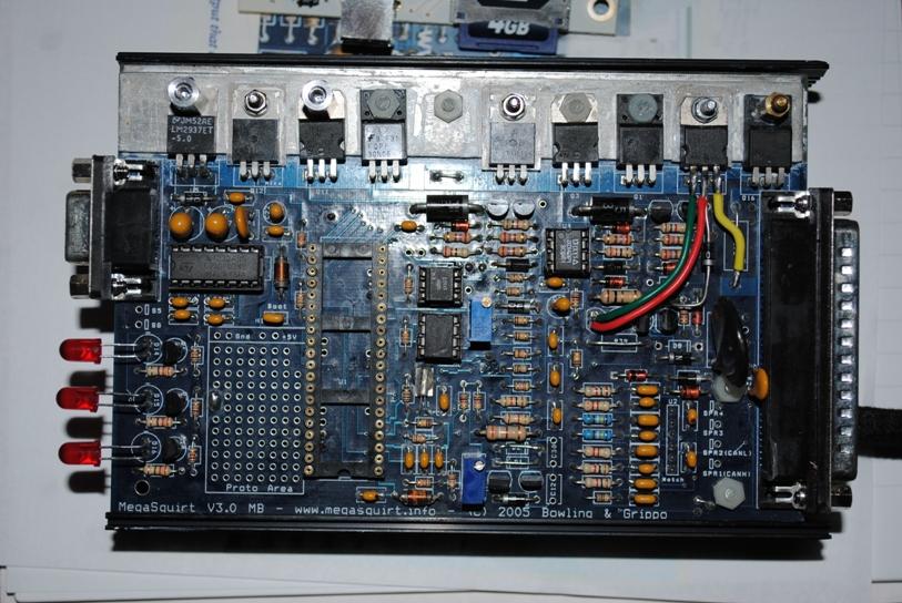
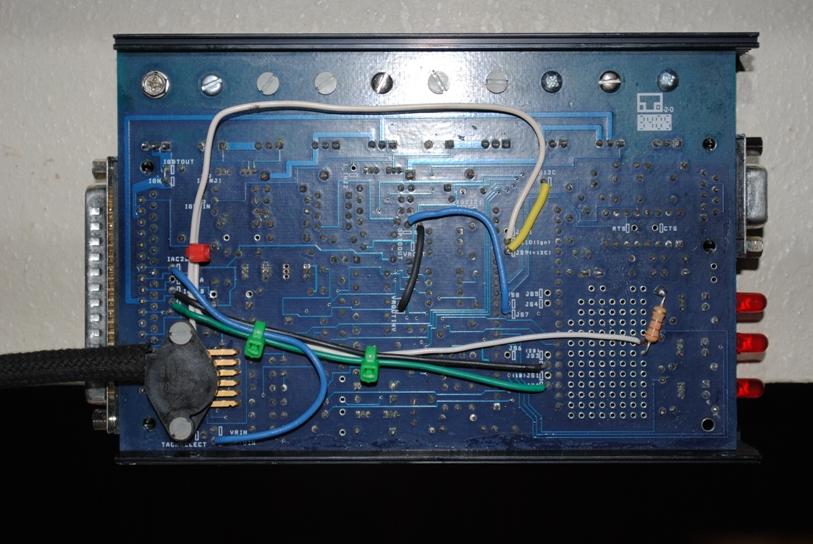
As just mentioned, I finally got the Megasquirt setup installed that I had build over 6mo ago. It is all hooked up on my current G60 8v setup, so I get any bugs worked out and get a base tune for the new motor etc. I am really beside myself as to how well MS works and it's capability After only about 30min of driving by myself, I have the car about 90% tuned. The software for MS is truly amazing...
Here is a quick data log from my LM1-LMA3 wideband. The spike just before boost is because I have Acceleration enrichment turned off for tuning purposes. It is still a bit on the Rich through boost because I had the Authority set low in Autotune, so that it was only able to make small changes at a time. Still learning the software and just need a bit more driving time before I can close this chapter. But not before a little Digi vs MS Dyno showdown. I still have Digi currently in there that I can swap back and forth with a harness plug change
February 06, 2007
A little update...
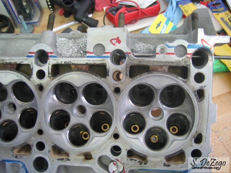
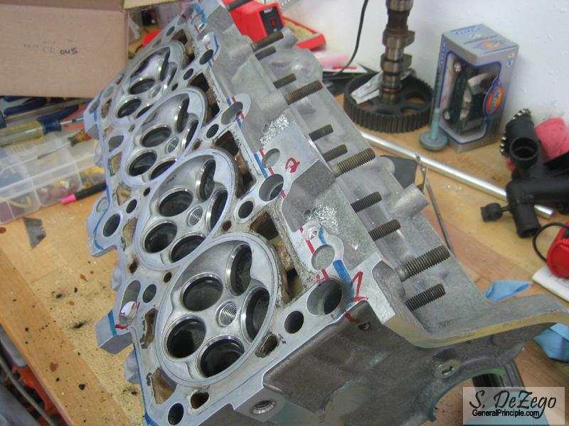
I finished the welding. The head was preheated and slow cooled in my oven. You should have seen my wife's face when she opened the oven to cook some pork chops I also did some rough machining and had it shaved for a finished HG surface. I went with the plan from the previous page (See Pic) and ended up creating the interconnecting oil drains to the corners. Welding this buildup was not fun due to the tight spaces and trying to get the TIG torch in there, but I managed.
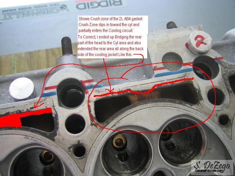
One Key note is that I was so focused on the oil drains that I noticed that the crush zones on the head gasket between the back of the head and the Cylinders impeded into/near/too close to the cooling jackets for my satisfaction. So, I ended up bridge welding those as well. (see annotated pic below)
Pics after the machining will be up tomorrow. (click to enlarge)
Drilling the Oil Galleys
Plugging the Oil Drains machined from AL Rod to aid in Plug Welding
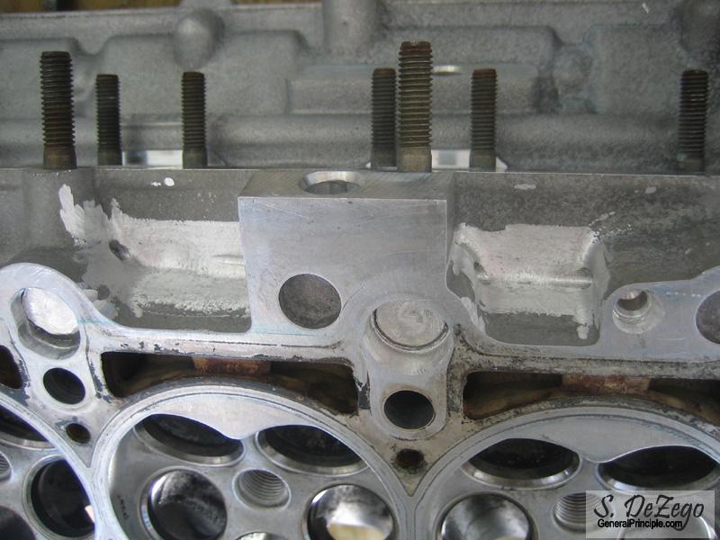
The HG Crush Zone I was referring to
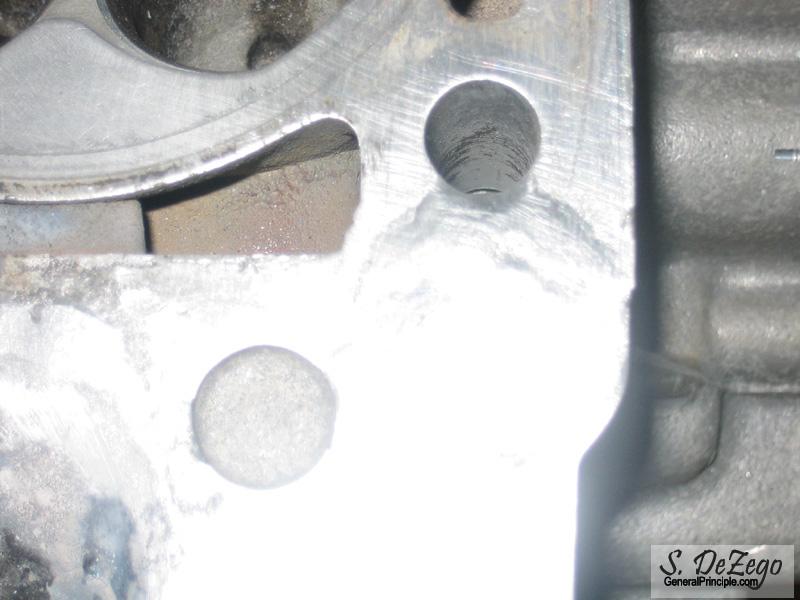
One of the corner drains welded but not yet machined (very poor pic I know)
February 07, 2007
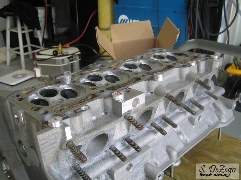
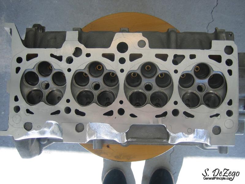
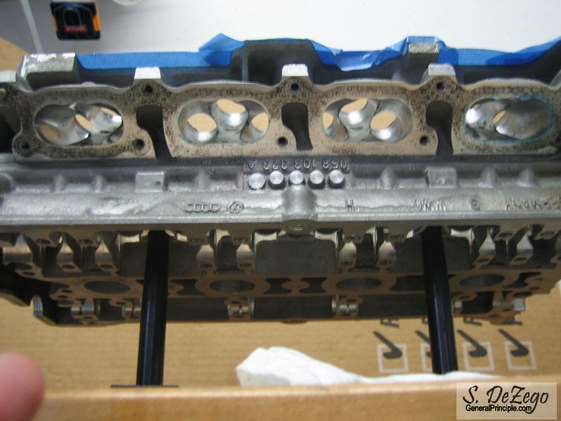
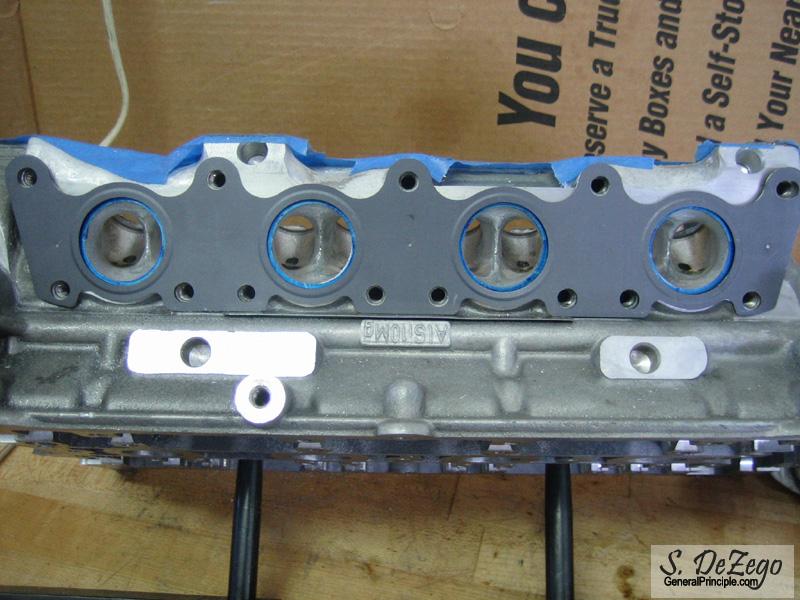
Teaser Pic. Notice the build up areas on the Exhaust side for the new Oil Drain Galley(s) interconnecting the 3 center drains to the corners respectively. Also, notice the now bridged area between the Cyls and the rear (exhaust side) of the head.
Have not finished the machining here:
- Corner Block Drains have not been redrilled
- Rear Coolant passages, not opened up yet to match Headgasket.
- Large offset front drain not remachined
- Head has not been PnP'ed yet
Before and after:
February 12, 2007
Head Modifications progression recap. (Before-During-After)
- Welded and block 3 rear oil drains
- Welded and re-machined 2 rear corner drains
- Welded and re-machined Front left Oil Drain
- Bridge welded rear head to cyls and modified rear cooling circuits
- Welded material on rear of head to interconnect Oil Drains that were blocked off to each corner drain via Drilled oil galleys
- welded and redrilled head dowel Line up holes
Before and after:
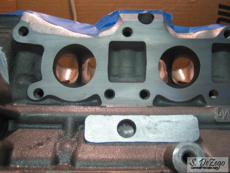
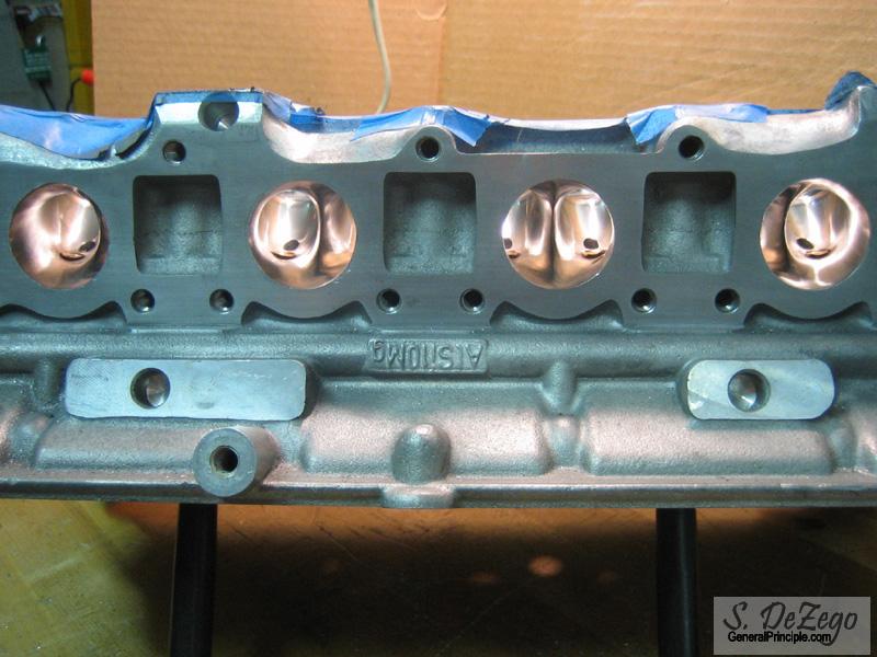
Now that the head modifications are pretty much done on to other head work
Teaser:
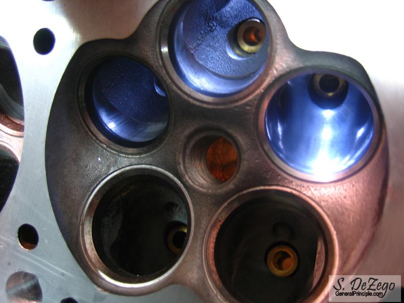
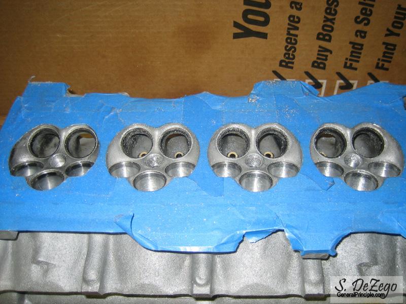
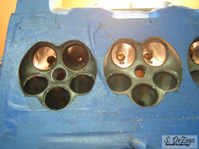
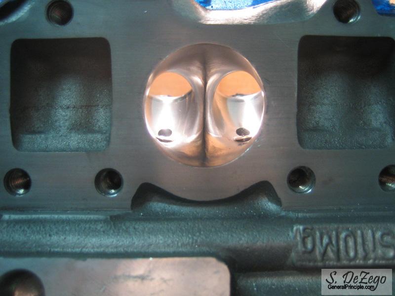
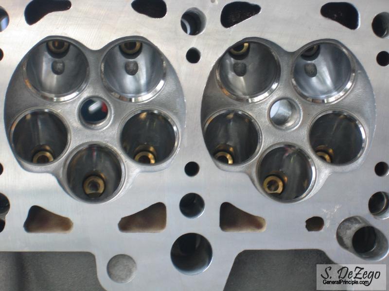
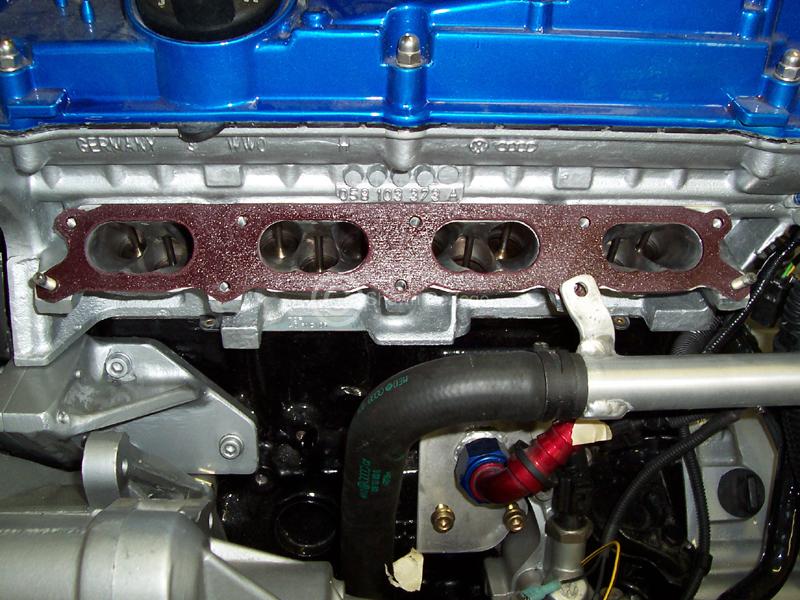
Edit: I should add, the left two intake ports are unmodified in that pic. Look at the transitions to the bowl area. If the head flows as well as it does stock, imagine what it will do with a little port work.
March 20, 2007
Thanks guys! If there were 30hrs in the day life would be good
Too many projects that are taking precedence which is why there is not much progress in the last few weeks
Like this one for example (Not related to this build).
April 04, 2007
Just too damn busy in general. I spent the last 36hrs alone in Tax preparation hell
And, as usual, other people stuff takes precedence over my own. But that is done and here are some pics of some 8v love (full thread to come).
...Letting the owner do the fine finishing inside if desired.
...
...
..
.
However, with all that said, last weekend I made good progress on the head and have all of the intake ports ported (Yes all 12 of them :bandhead: ). Not all polished yet, but I will take some update pics.
I am also questioning my Trans heavily and am seriously thinking about an 02m with maybe a 3.94 of 4.11 'ish Ring and Pinion. I hate the G60 gearing. I just need to find someone that will either make some form of a trade trade for my Silver Corrado or buy it outright, etc.
Shawn
I am most certainly considering that as an option. Unfortunately, I sold the Vr trans that I had as part of the swap Might need to look what I can get the gears for. In addition, if I stay 5spd, I definitely want a .72ish 5th. I miss that from my Turbo Scirocco.
..the 02m though, adds just enough complications that could quench my OCD briefly Realistically, the 02a with Vr gears makes the most sense.
LSD is happening regardless of the choice.
April 23, 2007
haha, yea no doubt. I have some updated pics that I need to post, but was hoping to get all of the PnP finished...
As it stands, everything is now ported. I just need to sand and then polish.
Thanks Frank. Actually, I really respect your opinion and experience with the different gearing on the G60 and 2L stroke. We had even discussed it a couple of times as you may recall, and if it weren't for that, the decision would be final to do away with the ATA. Your experience with it on the 2L, is really making the decision hard.
I still have time before I need to make a final decision on the gearing, so I need to do some more figuring and research. I had an AYL and sold it, but don't really know how noticeable the small difference is between the ATA.
I really want to go 02m for a few reasons:
- The gearbox is built to withstand a lot of punishment from the get go.
- they generally have much less wear than any 02a. Even mine which was well taken car of.
- The gear changes seem so much more refined on the 02m than on the 02a. This is the big one. I figured I could play with the final drive if I had to make some adjustments. Adding a shift weight on the ATA may help quite a bit, but after knocking through the gears on an 02m, I was all smiles.
I already have a brand new Light Eurospec steel Flywheel, new Vr PP and clutch awaiting, so I might just bite the bullet and buy the peloquin for the 02a and call it a day. 1st gear just really disturbs me on the ATA as you are in and out of it so quickly. Maybe it will be better as you cay on the longer stroke.
We'll see and thanks!
Shawn
April 24, 2007
A couple more pics I came across of some older progress. I am no longer using the AWP timing belt tensioner pictured below since I switched to non-Distributer (using the 9a IM shaft and stuff). Now, I can fit the 9a tensioner with one of my custom 157T Belts.
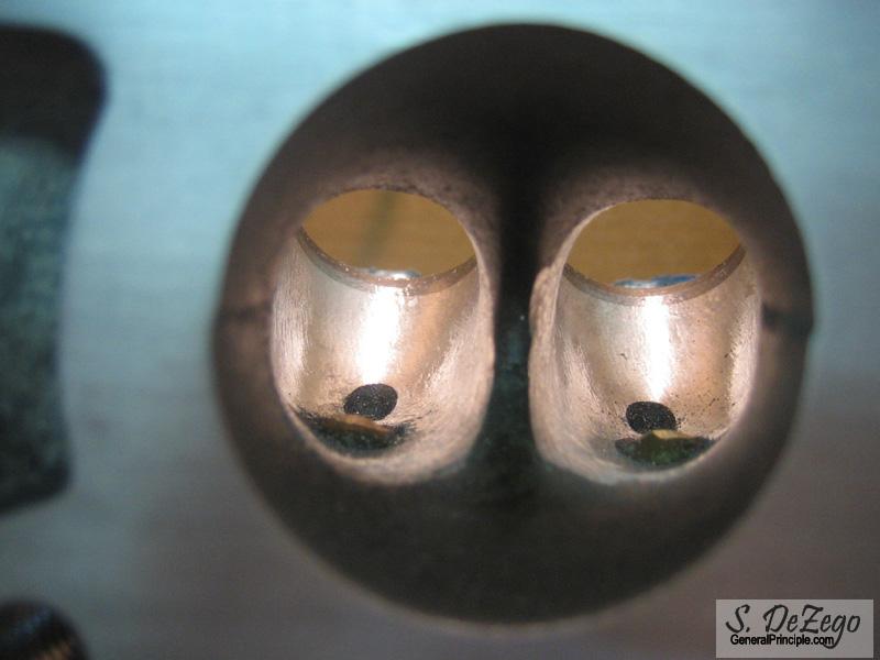
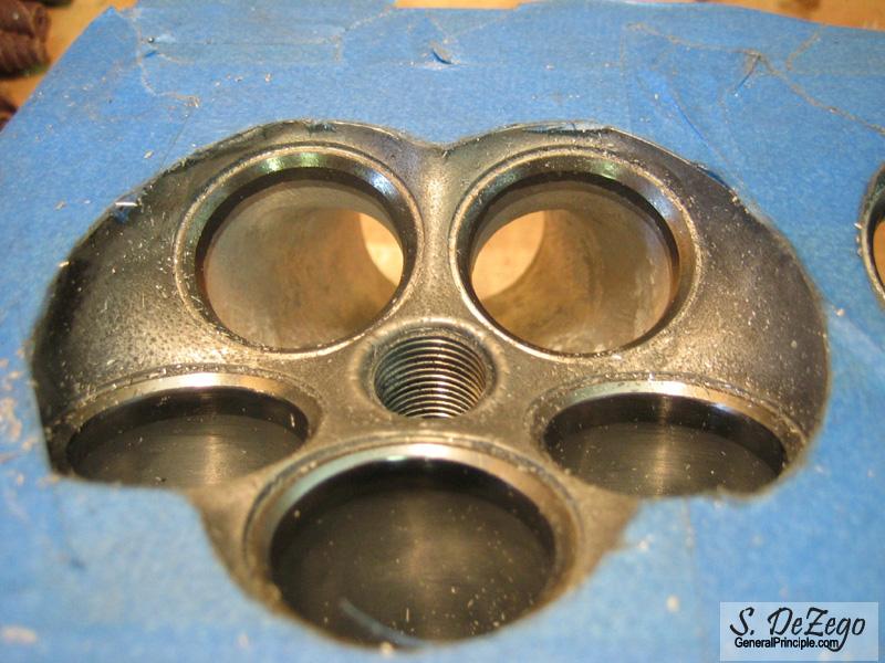
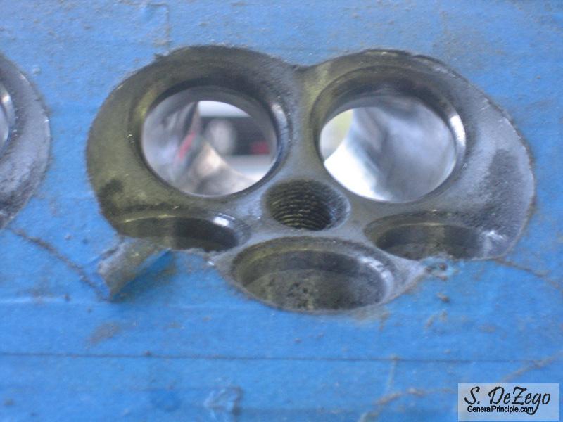
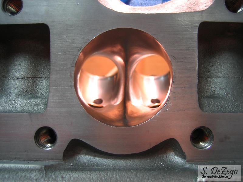
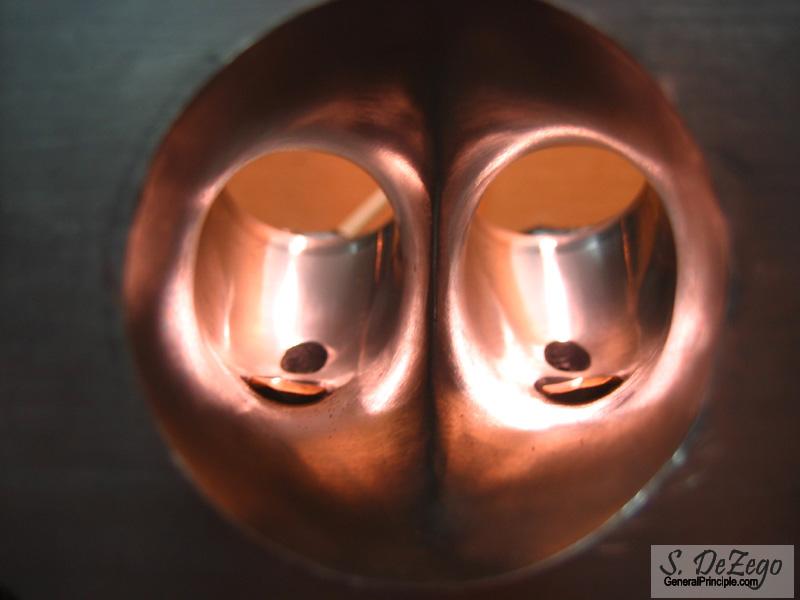
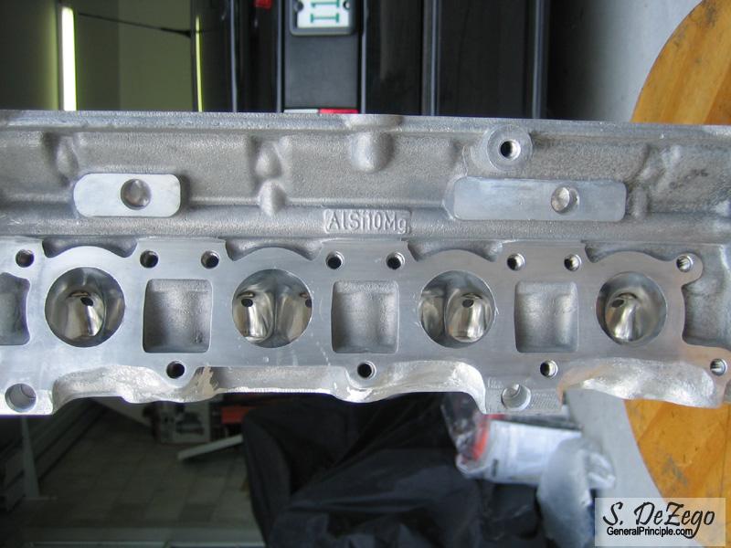
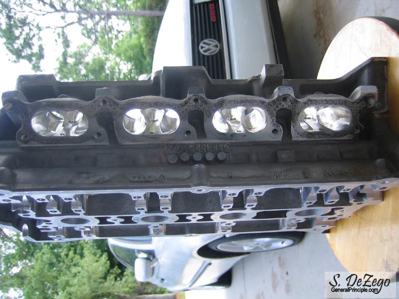
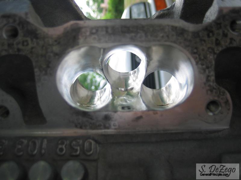
Before I post some more Porting progress, I just wanted to post this older picture of a finished intake port. Look closely at it compared to the untouched ports and you will see that there is some very poor bowl work and castings from the factory. Even still the AEB flows ~220-240cfm stock. Ported, it has been proven to flow ~ 270cfm.
April 25, 2007
Exhaust ports are 95% done..
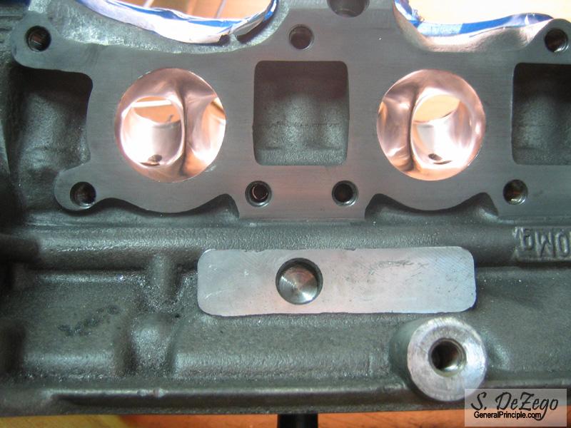
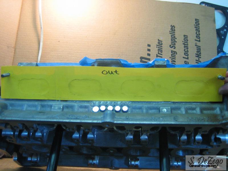
TEMPLATE for Port Matching the Intake.
Yea, I posted some flow number above in the barrage of images last night.
Stock, the AEB flows ~220-240cfm. Ported, it has been proven to flow ~ 270cfm+. Bob Quindazzi (mainly in the 1.8t forums) has some numbers from the heads he ported iirc and they are/were in the 270+ range.
It always helps and it is free hp. The differences that I have made by headwork alone on various engines over the years was my drive . I figured since I am not running a Big Turbo, I might as well make the best of it. I would like to put a set of cams in it, but I am not sure I want to spend that chunk..
I heard that Nate Romero ended up getting 240whp on his all motor 2020 . His ports are completely reworked and monstrous. There are some pics floating around the 1.8t forum iirc. That type of work definitely requires a flow bench and a LOT of trial and error. Obviously, he had very different goals in mind
April 26, 2011
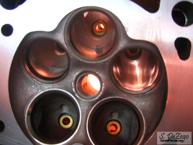
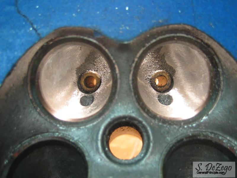
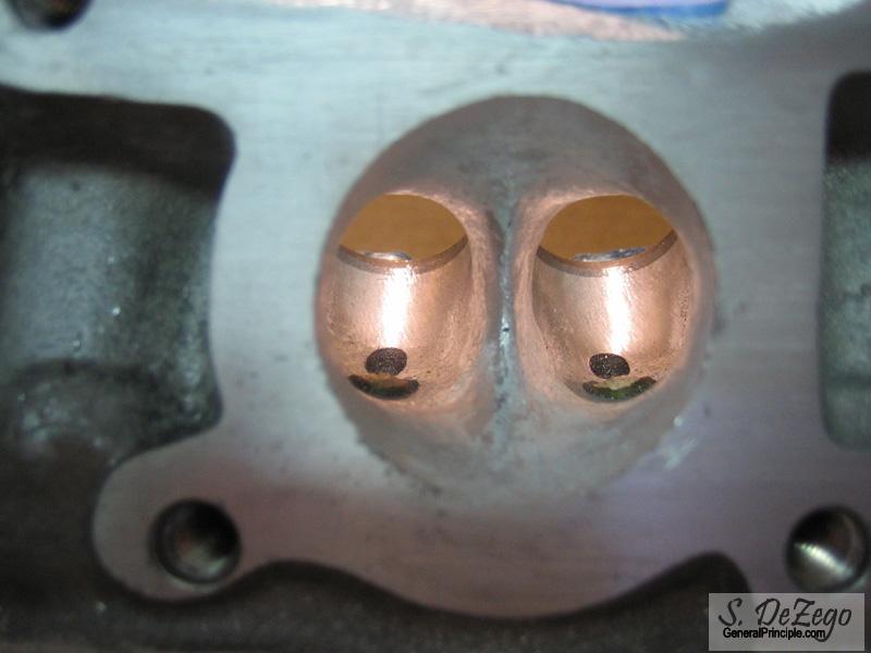
Here is a pic of one of the intake cyls that I had finished a little while back.
April 29, 2007
Porting is finished!
May 04, 2007
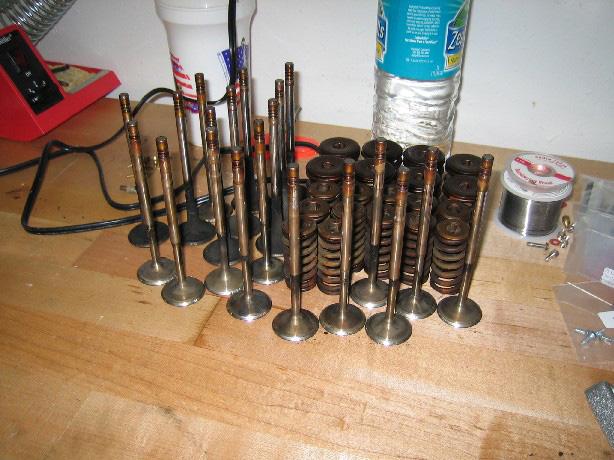
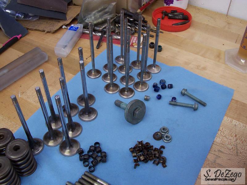
am using Stock valves since everything was in good shape.
My opinion is that I see no point in going oversize valves because of the head shrouding and closeness of the valves to begin with. I think the big gains here are the porting and bowl work and enlarging the ID of the seat slightly (i.e. under the 60* cut into the bowl). Also, there are significant benefits in Sodium filled Exhaust valves that I would rather not just throw away.
Not saying that there is no value in the very small OS valves available, just not worth it for my project goals and is reserved for the ballerz If, I needed all new valves, I would consider it.
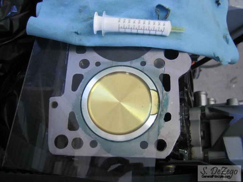
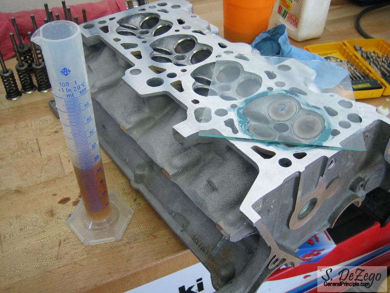
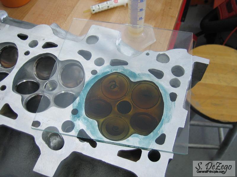
I just cc'ed my Cylinder and Head (#1) because I want to see what my CR is. Since, I decked the block and had to shave the head slightly after welding, I want to make sure I am still where I want to be.
I will post those details this weekend and still want to polish the Combustion chambers. I also planning on claying the pistons to check and verify valve clearance. I am sure they are fine as JE made the pistons, but I want to check in case I decide at the last minute to drop a set of cams in here
S
Forgot to mention that I removed all of the stock oil galley Ball Bearing plugs. what a PITA.
I just got my 1/16" NPT (Pipe Tap) yesterday (hard to find locally) and am going to allen plug all of them. I decided to do this to clean all of the oil galleys and make sure there was no debris/residues caught in any of them.
S
May 05, 2007
I just cc'ed my Cylinder and Head (#1) because I want to see what my CR is. Since, I decked the block and had to shave the head slightly after welding, I want to make sure I am still where I want to be.
The question "What is my compression ratio" gets asked a lot in the various forums, so I figured that I would "show my work".
Here is some stuff that may help
CC = Combustion Chamber (Referring to the physical chamber itself)
cc = unit volume cubic centimeter or cm*cm*cm or mL (mili-Liter)
PV = Piston Volume (At TDC to top of block)
CD = Cyl Displacement
HV = Head Chamber Volume (approx 43 cc for stock 20v)
HGV = Head Gasket Volume (depends on final Gasket thickness!) (Pi*R*R*Thickness)
My 2l= 92.8 Stroke and 83mm Bore = 2008cc
Cyl Dis (CD) = (Bore x Bore x Stroke x 0.0031416) / 4 = (2008/4 = 502 cc)
HGV = 8.66cc (~1.6mm Compressed for stock 2L MLS)
PV = 9cc (Measured)
HV = 42cc (Measured)
Compression Ratio = (CD + PV + HV + HGV) / (PV + HV + HGV)
Note: If you have a compression ratio goal you can work backward.
CR = (502 + 9 + 42 + 8.66) / (9 + 42 + 8.66) = 9.41 :1
I wanted to be around 9.25:1, but since the block was decked and the Head was shaved slightly, it brought it up a bit.
I am going to remove 1cc from the CC when I polish them which will be perfect.
Shawn
cc'ing the HV and PV
May 24, 2007
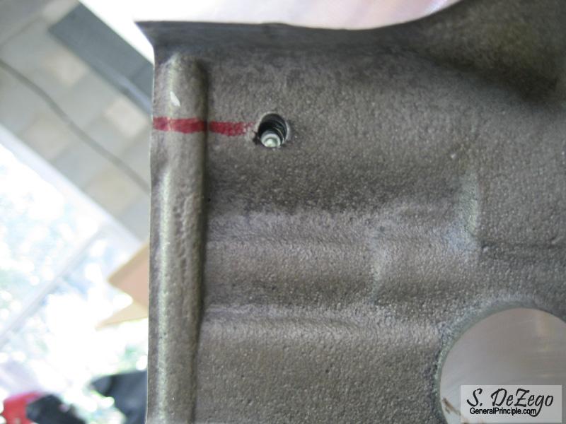
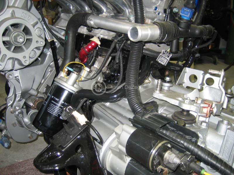
similar, but the head is "Last in Line" to get oil pressure per say and the oil galleys are small in comparison to the oil channels at the filter housing. Drawing from the head might drop the pressure in the head slightly (i.e. hydro lifters, journals, etc). Since the G60 line is so small and flows so little, though, I am sure it is negligible though and is likely where it will end up.
I just got done tapping all of the Oil Galley plugs and did tap the one near the Coolant flange to M10. It nothing else, the Mk2 secondary Oil pressure switch is going there, but i will likely run the charger line off there as well. I have the pressure switch in there now and it looks factory
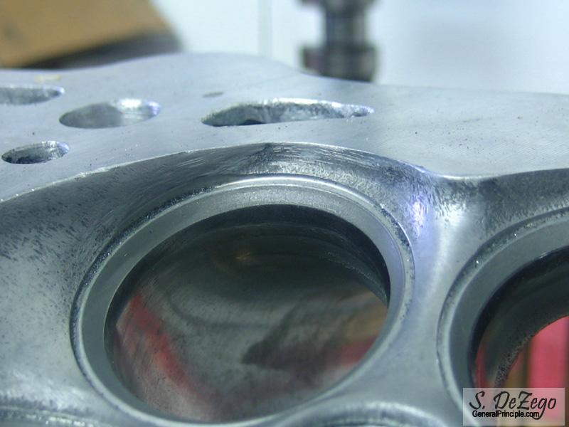
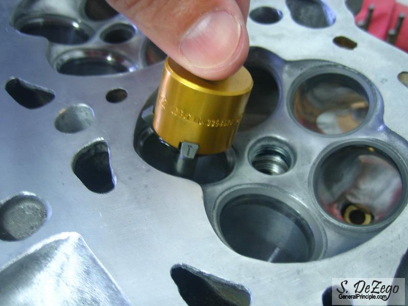
A small update. I went to finally assemble the head and hand lapped the valves to check them. 3 of the Ex seats had an ever so slight issue. I am not really sure from what (Factory possibly), but it is enough that i want to fix. My neway seat cutters were way too big for the 20v head so, I have the right set coming so I can clean up those Ex Seats. I'll have some pics to clarify it and hopefully my cutters will be here before the weekend.
Baseball season is over (I was coaching), so now I have my spare time back and am ready to get down to brass tacks..
Shawn
June 10, 2007
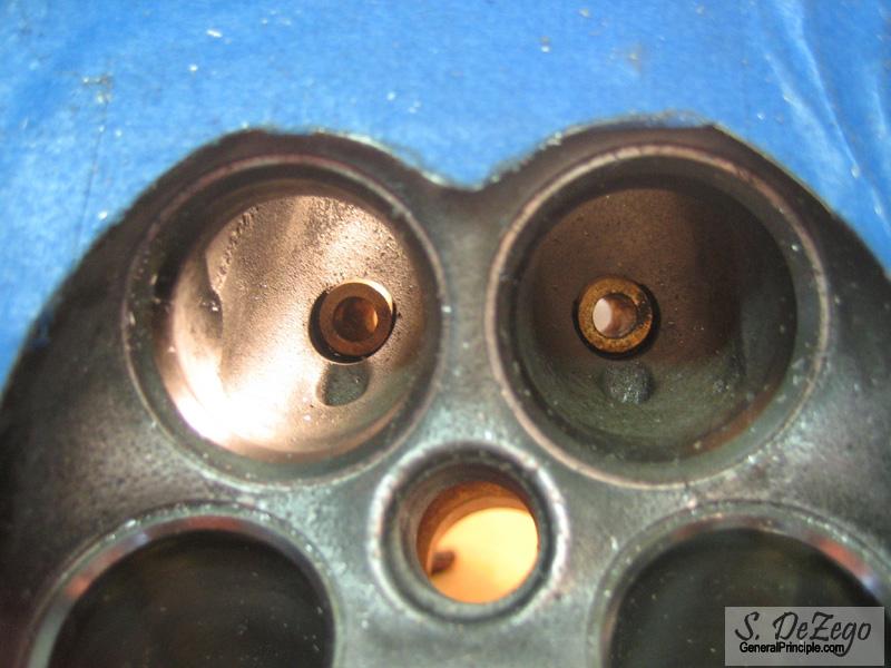
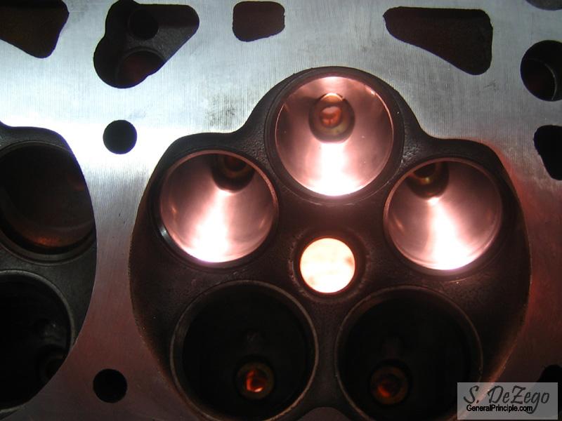
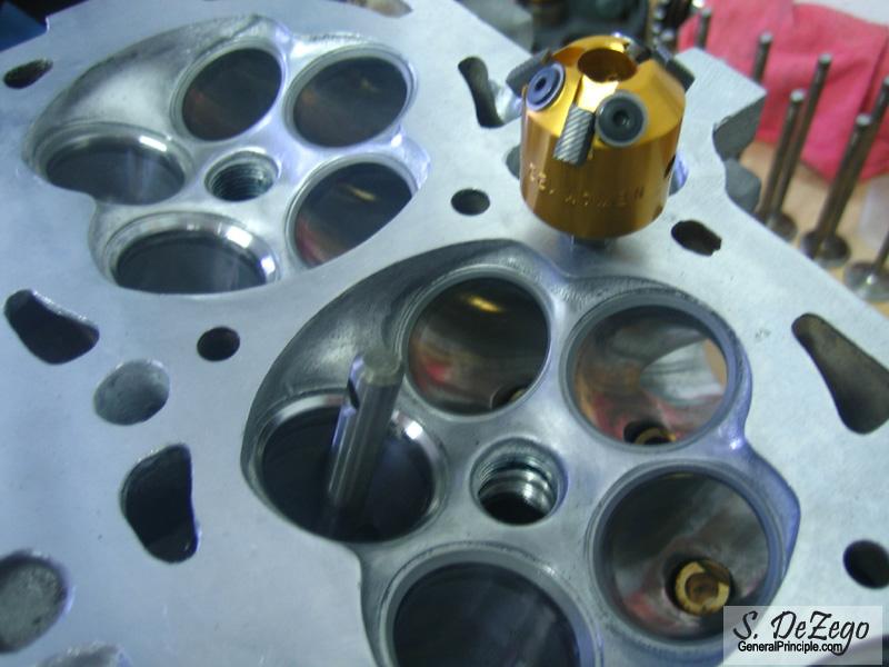
Good progress this weekend for a change. As I mentioned above, I wasn't happy with the way the valves Hand Lapped in, so I decided to do a valve job. In the First pic, you can see that there is an area on the top of the Exhaust Seat that the valve did not lap in properly showing there is some seat distortion for some reason. There were 3 ex seats like this, but I decided to cut all in/ex seats.
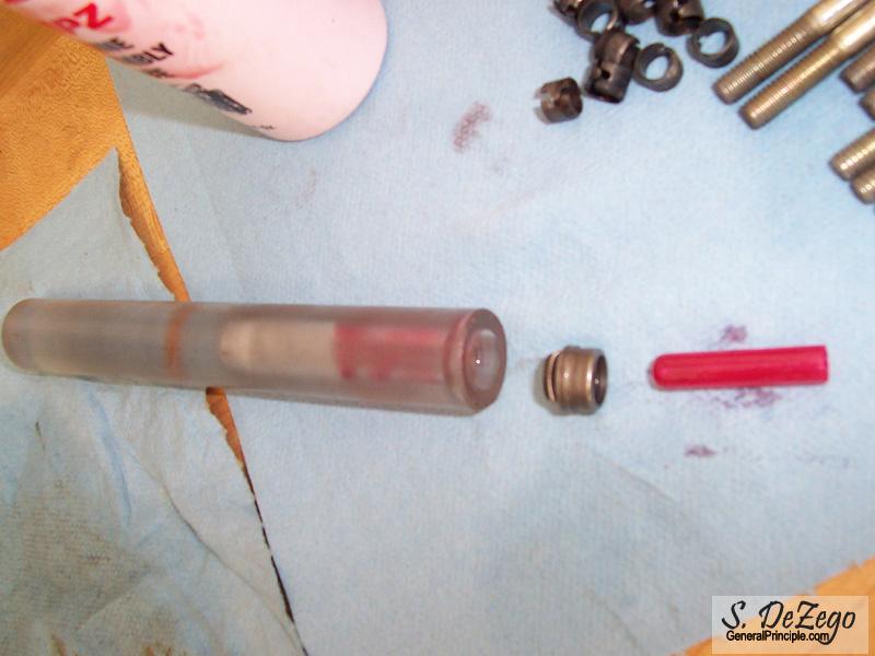
Also had a spare piece of Lexan Rod and made up a valve seal tool on the lathe. Worked flawlessly as you will see.
June 11, 2007
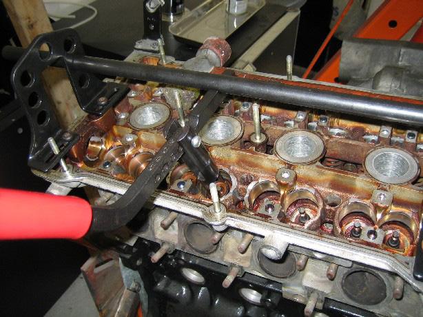
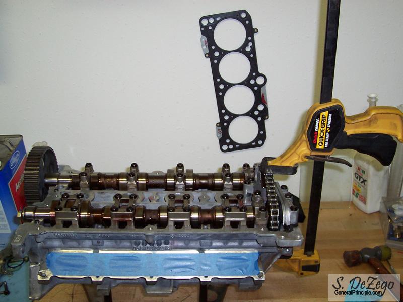
Head going together
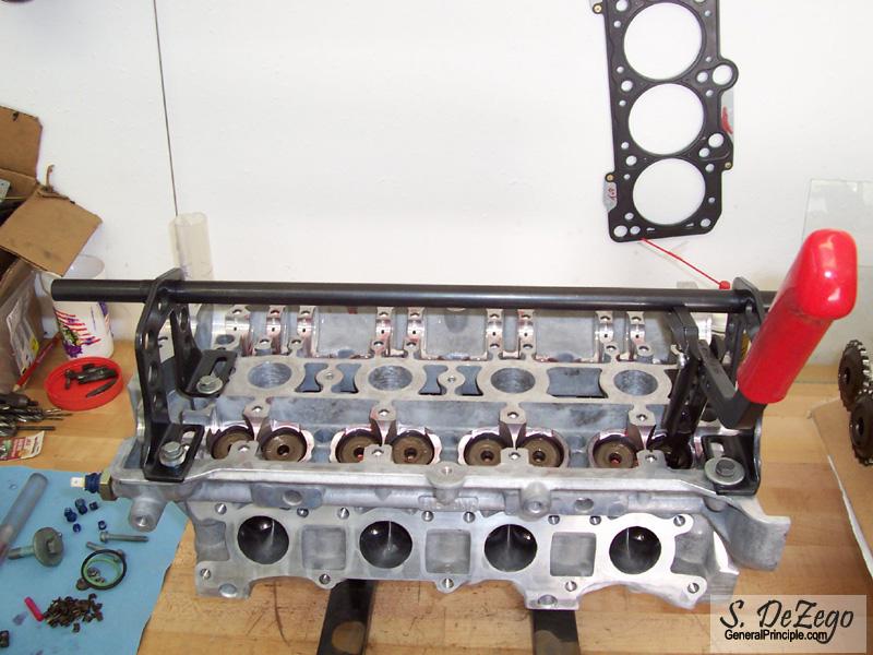
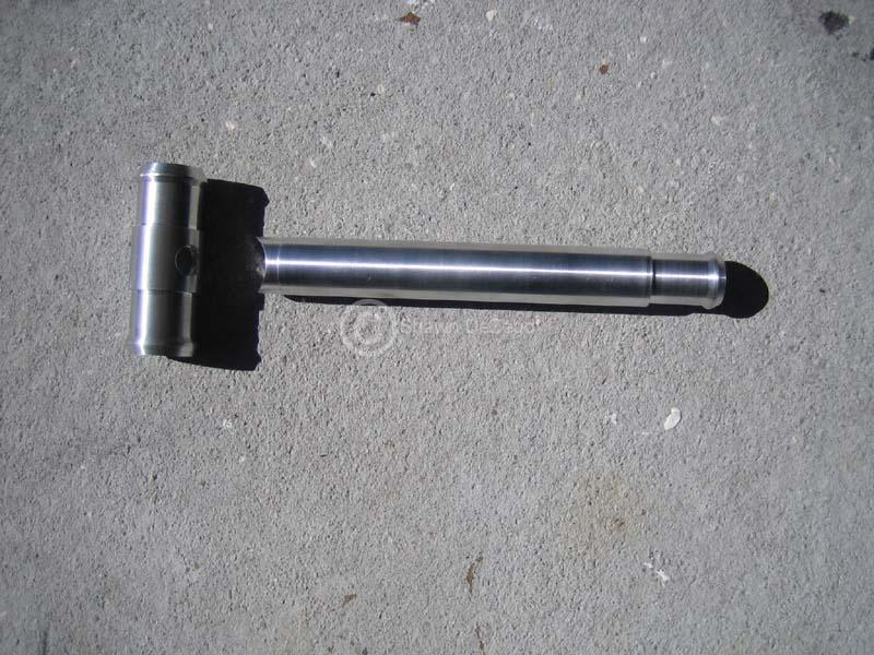
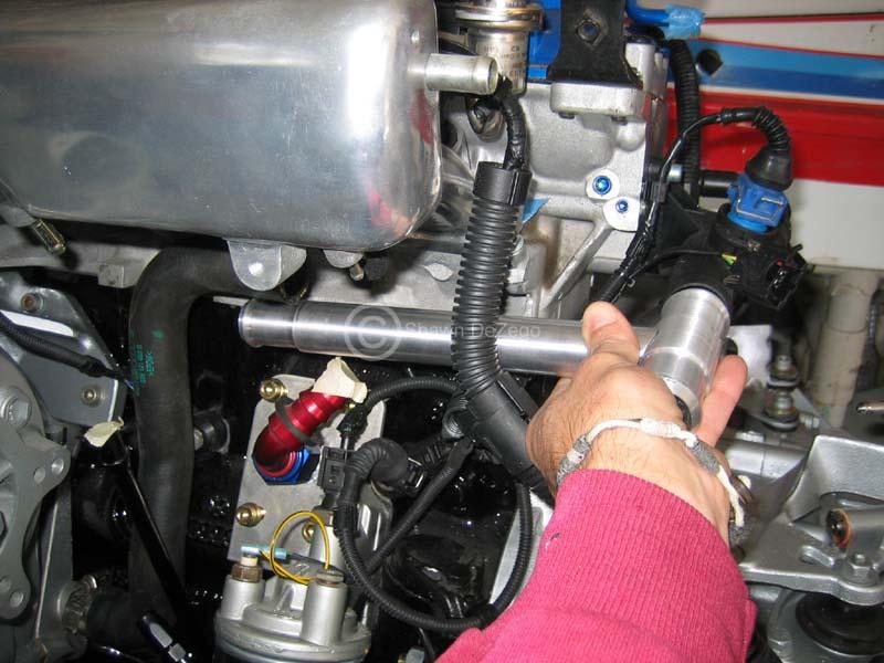
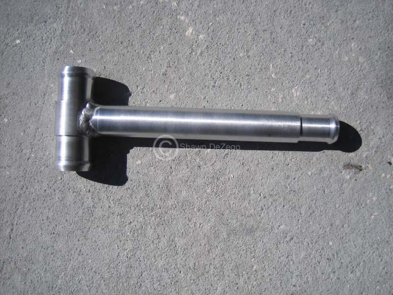
My highly technical Cam Chain tensioner Compressor
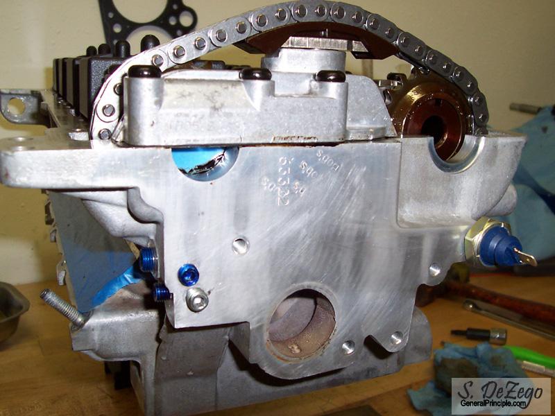
For those Familiar with the 20v head you will see that I removed all of the oil galley ball plugs to clean all of the channels. I Also tapped for the Head Pressure switch and tapped the holes for pipe plugs (not fully inserted in this pic).
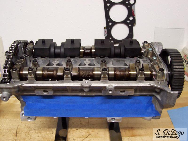
Head will be going on the block Tomorrow Until then, it's time for a beer.
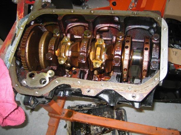
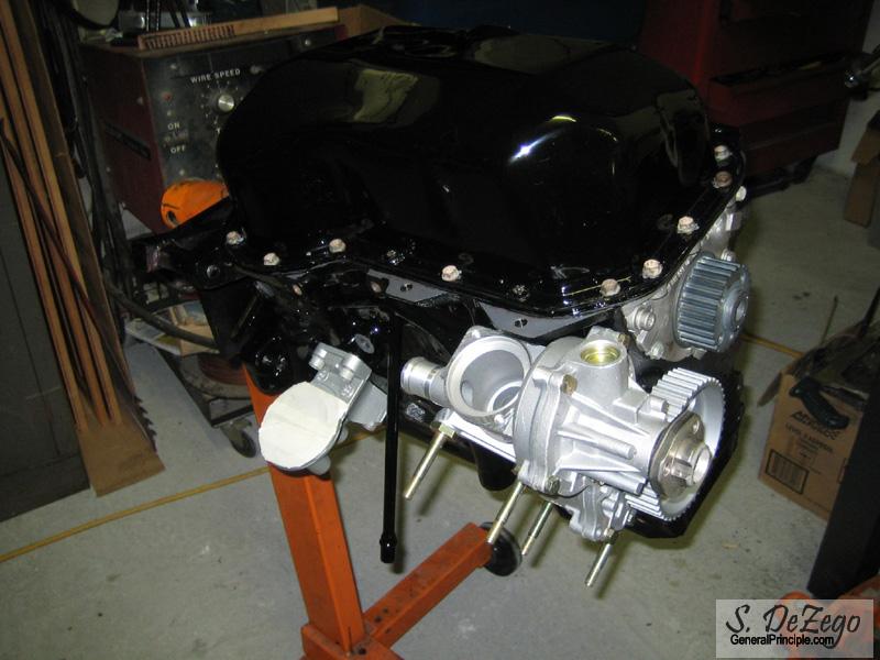
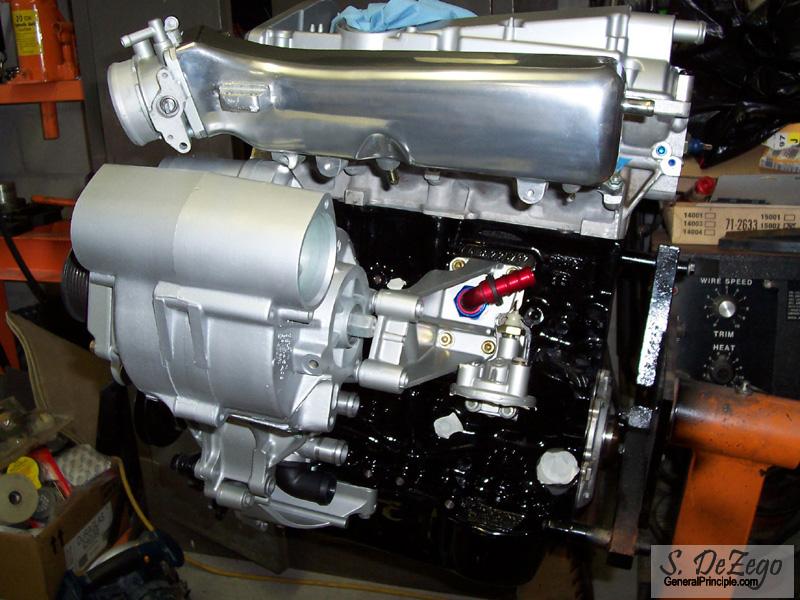
The Lid is on the Short Block and it feels like a big accomplishment!
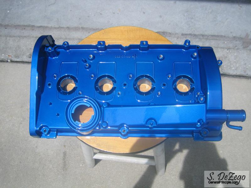
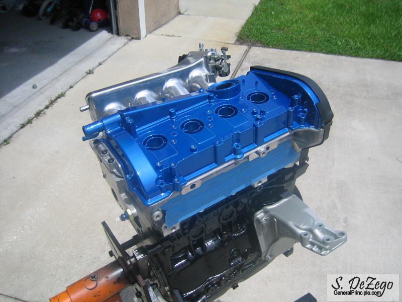
Trying to decide on what to do with the valve cover. I am thinking either Wrinkle Black or Powder Coat it Blue. Since the car is black, I am thinking that Blue Valve Cover and Blue Silicone couplers might not hurt the eyes. All Hoses and such will be black.
I did the Charger Brackets and such in a Cast AL color paint and really like that aspect. Need a few to think it over some more.
S
June 17, 2007
Thanks Matt.
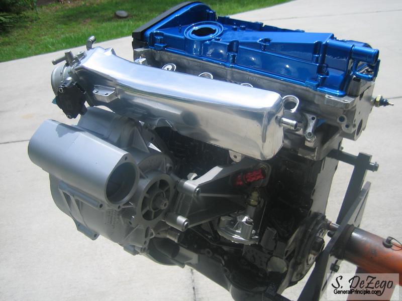
Here is a little update and regarding the pics below:
- Valve Cover is not powder coated yet and therefore not bolted on.
- Still need to come up with a spacer for the AEB timing covers to account for the taller ABA block. I have an extra set of covers, so we'll see.
- Awaiting adjustable Cam Gear to account for 1/2 tooth timing offset.
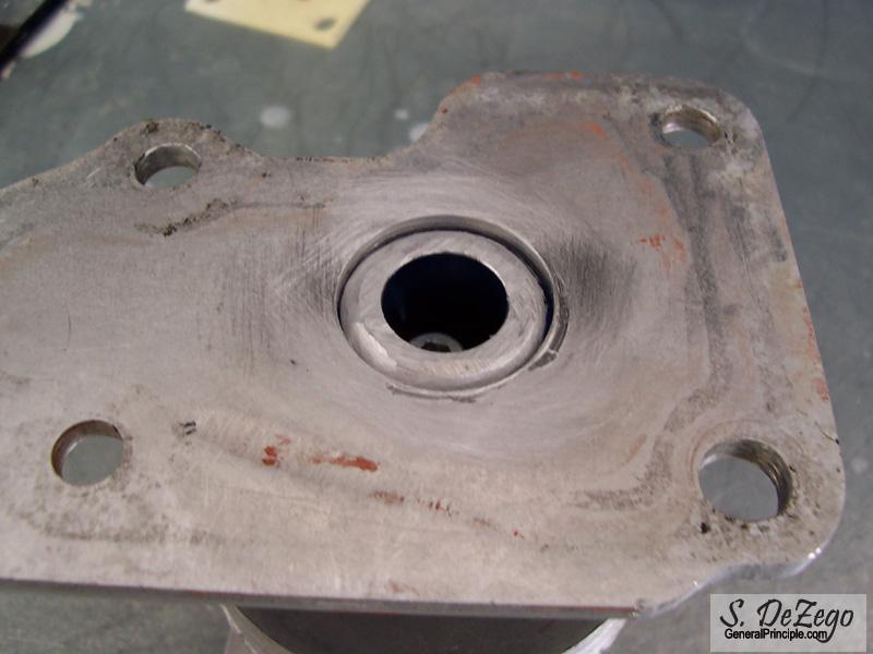
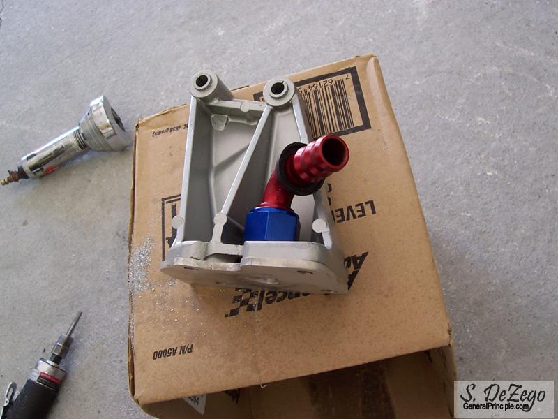
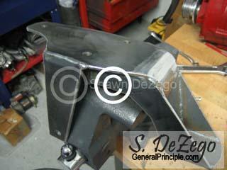
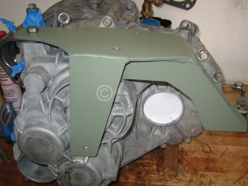
Welded an -AN fitting on the Breather Block off plate and drilled and milled the back of the Charger Bracket.
as always, Click for Larger Pics.
..ready to weld -AN Fitting
June 23, 2007
Thanks!
Intake is now port matched, but my freaking fingers are about to fall off and I am only about 3/4 of the way there grinding and sanding the intake in prep to polish. The factory casting was the suck...
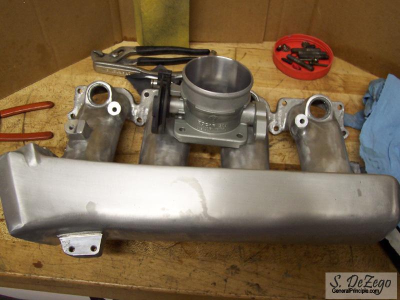
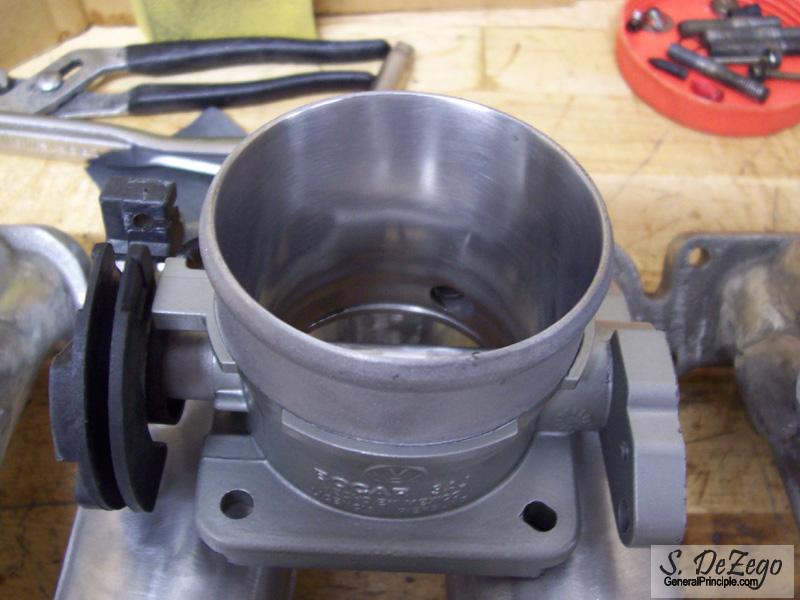
Anyway, was up at my brothers shop today to cut my wheel spacers on the lathe, so I also de-ramped, polished and painted the OBD1 ABA Throttle Body.
Pics as usual
July 02, 2007
Not much to report.
I was up in NC for a week for some R&R and just got back a little while ago.
also, been waiting for 2 weeks for ZDMAK to get me the correct Headbolt Triple square bit after they sent me an 8mm long Allen (AEB used 8MM TS and rest of the 20Vs use the poly bit). Early 8Vs use a 10mm Triple Square which I had, but was not help obviously.
i finally received it though as they stepped up and sent me the correct one at no charge.
I did decide on the color for the valve cover and hope to get it to the Powder Coater by end of the week Still deciding on the manifold and may do a 1/2 Polished 1/2 Powder Coat (i.e. the runners) the color of the valve cover.
Shawn
July 16, 2007
Never a dull moment.. Because of the deck height difference in the block, shaved head and IM gear combination, the Cam timing was off 1/2 tooth. So, I ordered a TT adj cam gear (because it has the factory steel hub).
..and of course nothing is easy and the factory cam bolt/washer would not fit, so I needed to cut the washer down on the lathe.
I didn't get the valve cover off yet, because of my indecisiveness on color. But, I did break balls finishing up the intake. The factory casting was so bad...
Everyone likes pics.
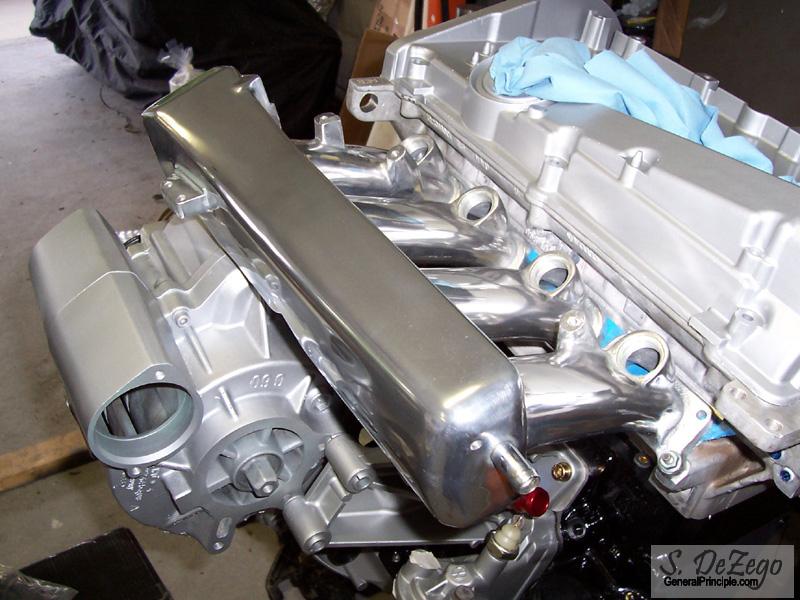
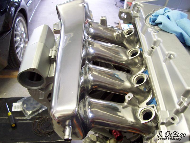
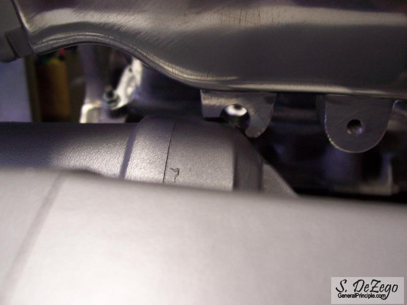
The only modification needed for the Euro AGU big port intake was to clearance the one boss over the charger.
July 27, 2007
I think my indecisiveness on the VC color paid off. I am thrilled at the results. It is a Candy Blue (silver Base).
September 10, 2007
Small Update:
I have been making slow progress just due to everything else going on, but will hopefully have a big surprise this weekend that will help get me in gear
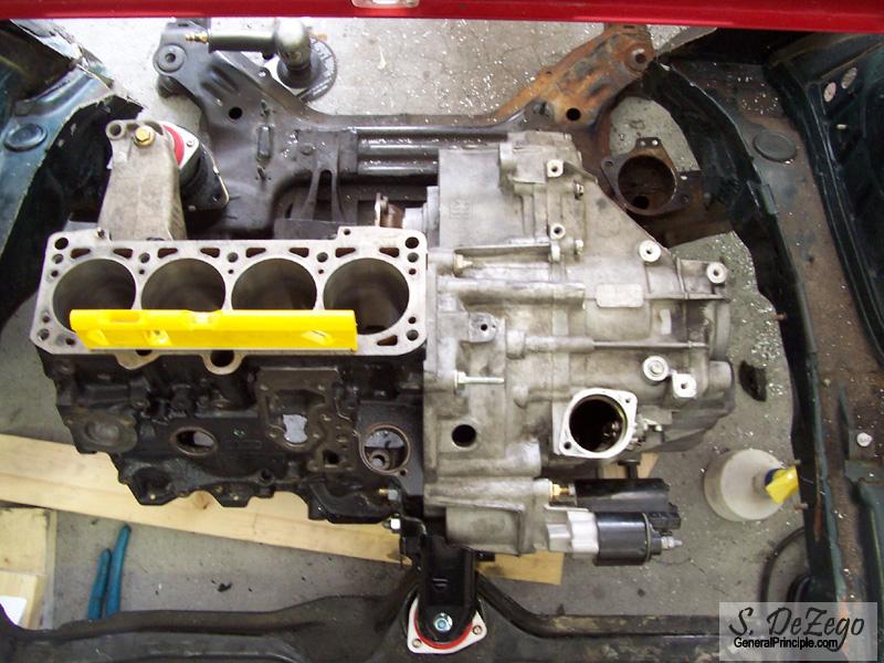
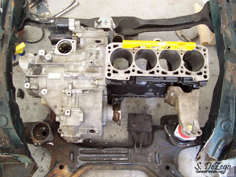
Do some checking on the ABA and you will see that the Engine is quite different (even in stock form) than the PG (despite its appearance).
- The Deck Height on the ABA is ~16mm Taller than the PG
- It is a 2 Liter Engine Stock with 82.5mm Bore and 92.8mm (i.e. 1984cc vs 1781cc on the PG) stock
- 159mm rod length (as opposed to 136mm PG rod length)
- Crank Triggered Ignition
- Piston Design (Wrist Pin, Skirt and Crown thickness)
The Rod Ratio or "Squareness" of the Engines are quite different due to the above.
I would rather not get into a whole discussion in this thread about the different engine(s) potentials, etc, but will end with one final thought:
Regardless of the above, the bottom end is somewhat irrelevant to the hp production but both are potentially capable of withstanding that much hp. It is the Head, cams, intake, exhaust, management and most importantly the forced induction system (how much Boost) that will dictate hp potential. The G60 charger is a major bottle neck above 250hp. It is an air pump of limited capacity (a matter of physics) and is restricted to a lot lower RPM than say a Turbo Motor. This is a major crux if your goal is all out hp (like it or not). But, I tend to like it as my goals are a bit different
S
September 16, 2007
The reasons progress was slow because I was getting My other Silver G60 ready for the sale (among other things).
...and with the silver g60's departure brought this little gem. An O2m 6speed is what I wanted all along for this project and now I have it ...along with some extra parts like a whole AWP
October 05, 2007
update:
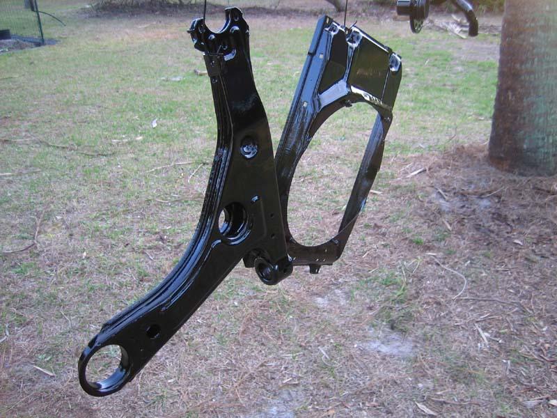
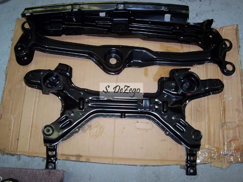
1. I am now going with the 02m 6speed trans that I acquired (as mentioned). Since I have to make motor and trans mount brackets anyway, I decided to hunt down an Extra Kframe, so I can keep my running car "running" during the build, mock everything on the floor and when the swap is ready, it will go MUCH faster with much less last minute fabrication. I am picking up the Kframe and rear engine brkt from my buddy Jeff this weekend (which is from a Mk3). So, I will be switching to the Vr style Rear engine mount.
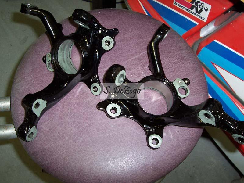
2. I will probably be using all of the Vr + suspension stuff for the front that I already have from the 93 Vr parting. I need to use Vr hubs regardless, so the splines from the 02m axles match up (still need to modify the length of the 02M axles regardless). The + suspension will eliminate my 10mm spacers in the front anyway and add a few mm to match my rear. I am a little concerned about scrubbing with the + though. I will have to re-drill 5Lug Hubs->4Lug unless I get new 5 Lug rims for the Ft. But this is all minor stuff that i am not worried about.
3. I also decided to pick up a Vr front Engine carrier to run a Vr style front engine mount. Again, I needed to fab up a new front engine bracket anyway and the Vr carrier is stronger.
4. 1.8t Fuel rail is now modified with -AN fittings on the rail (will post pics of the mod later)
5. In my endless quest to make things as complicated as possible, the Serpentine belt route is pretty much decided and rear mount alternator bracket is well underway. I am using the "clutched" 1.8t 120A alt that I picked up with the AWP (which I am happy about). This setup reduces stress on the crank bolt due to rapid deceleration which is a bonus. One thing to note here is that I will be running only one accessory belt (no Serp + V belt as stock). A Serp belt will run everything -> (H20 Pump, PSteering, G60 Charger, Alt and A/C)! This was a trick and a half Pics of this soon.
6. I am having to spend a lot of time trying to research what I consider the perfect clutch setup for the 02m. This has been very frustrating due to what is currently available. Going from a 240mm clutch to a 228mm setup (as most vendors try and persuade) makes about as much sense as a horse with a kickstand. Granted my power goals are meager when compared to a Big Turbo setup, but I can't break myself to do this. ...it's like swapping your big brakes for smaller ones . The stock Dual Mass 02m flywheel is extremely heavy, but the AL lightweight flywheels most people sell are a bad idea for reasons that I won't go into right now. Spec, makes a very nice steel Flywheel with what I am looking for in Weight (~14lbs), but I am not sure I trust their clutch setup from all of the bad raps in the past. I have no personal experience with them, but the problem is trying to find someone else with the 240mm Clutch disk and PP that is not for the Dual Mass and has a High Torque sprung hub. I am very close and I will post much more on this, but if anyone has any questions in the mean time, feel free to ask. Either way, it looks like I will be in for about a $G and close to 2Gs if I add a Peloquin.
This read was for the non-window shoppers
Shawn
November 07, 2007
Not after recently picking up the following:
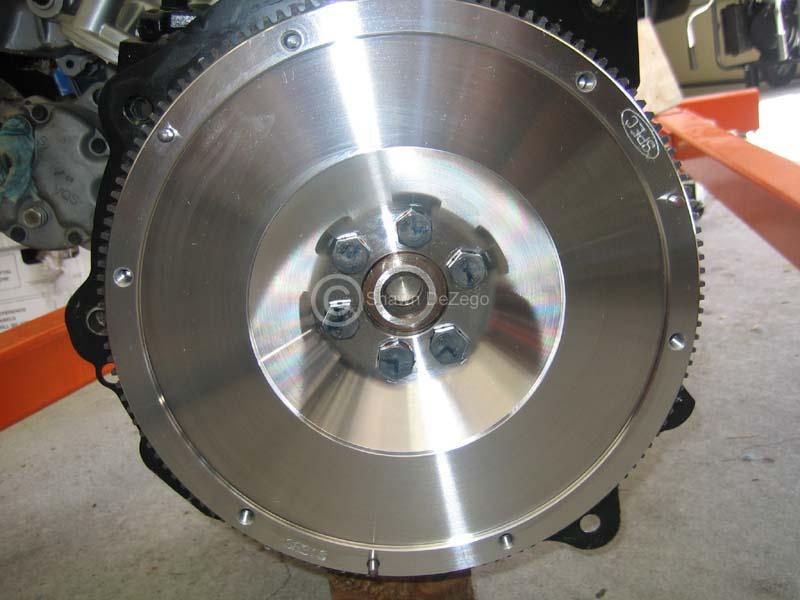
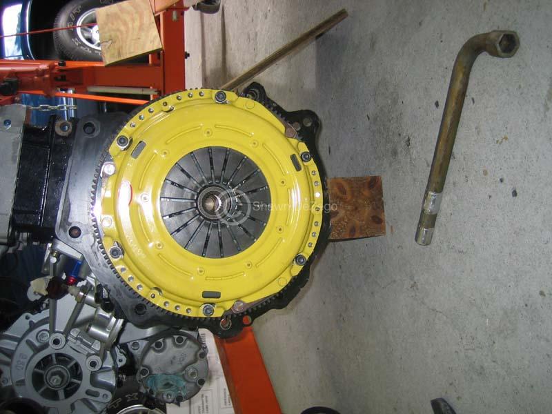
- 02m Flywheel (SPEC 16lb Billet steel Single mass ) Thanks Scott - USRT
- ClutchNet Yellow PP and Kevlar Disc - Sorry Scott for not going with SPEC
- Genesis 550 injectors with adapters - Got a good deal on the package
- 02m Peloquin
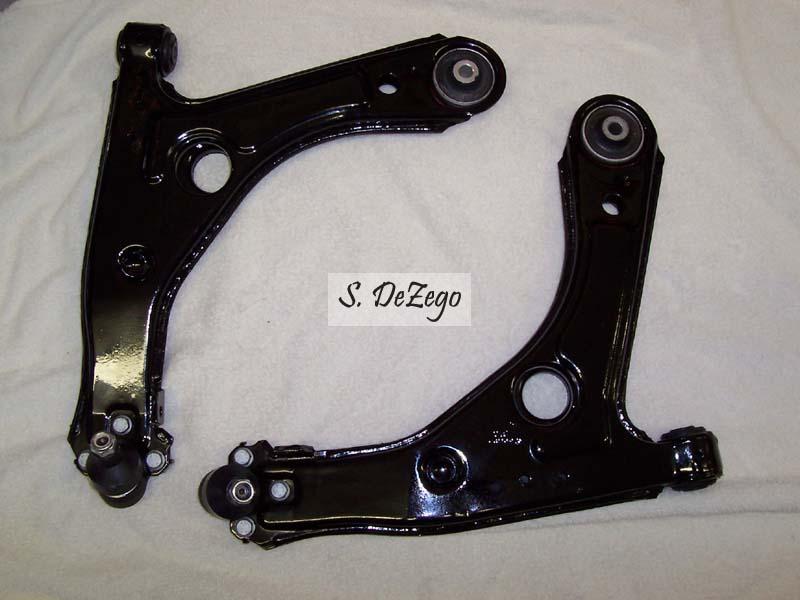
- Complete VF mounts and all new front suspension joints/bearings (again). I think I mentioned I was going to the +suspension that I already had.
- misc 02m parts (lines, slave etc)
- Spare K frame and VR front Carrier so I can fab all mounts and such on my Bench/floor mock engine bay. I can also paint and have it ready to go with the engine. (remember, I am still driving my Corrado which is part of the reason for taking my time)
I will have some more progress pics coming soon. I have the rear Alt setup about 99% done and serpentine belt setup about 80% done. I do not want to show any pics until it is complete though. I think I mentioned that this is a single serp belt with no vbelt! Running ALL accessories including A/C and PS
Oh yea and 02m is apart and Peloquin is pretty much installed. ...just need to order the proper diff shim.
November 08, 2007
Here are a couple of pics from what I was describing above.
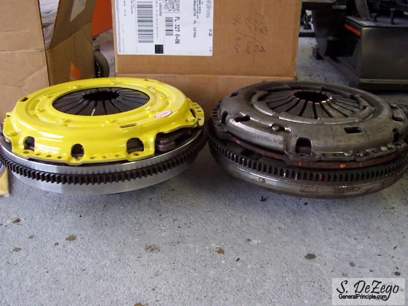
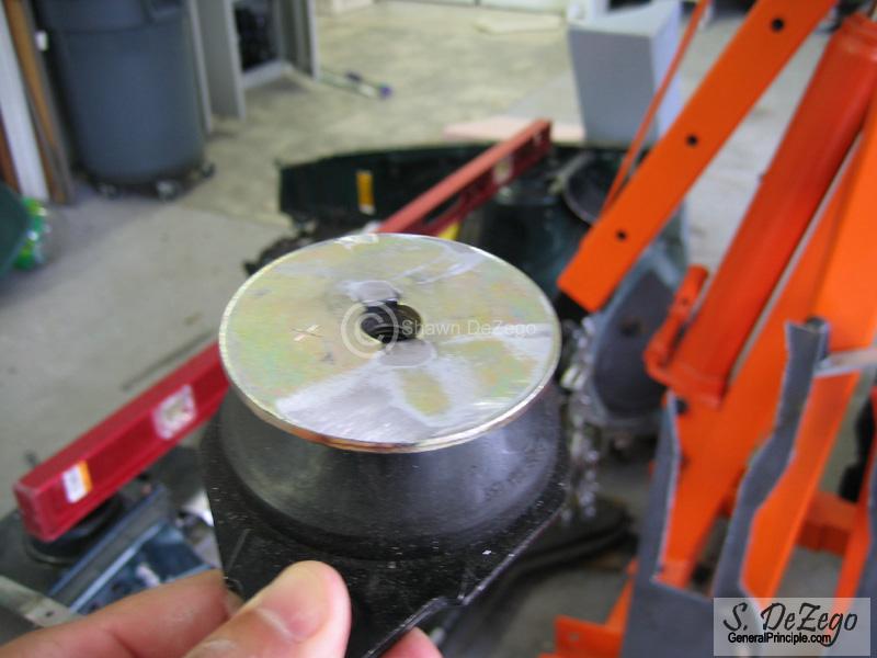
Stock 02m 240mm Dual mass flywheel (26lbs)
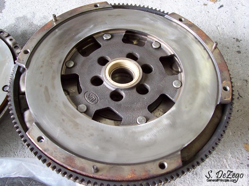
Stock 02m setup vs SPEC 240mm custom 16lb billet steel flywheel with ClutchNet PP. The measured specs on the whole setup are precise. The SPEC FW is a very nice piece. I do not like Aluminum flywheels for a number of reasons. AL transmits harmonics very easily and the Steel friction plate can warp. Plus, most of them are too light for my liking.
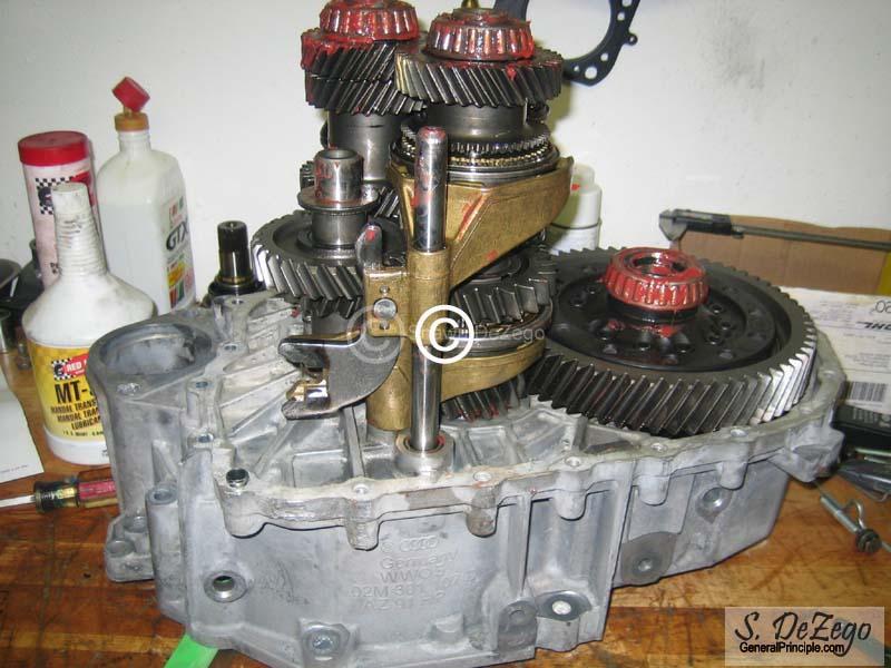
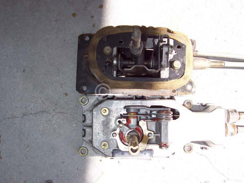
Installing the Peloquin.
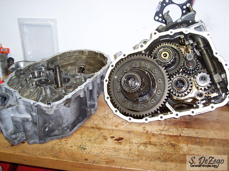
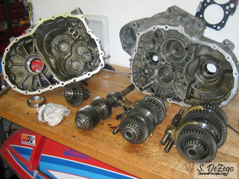
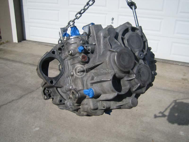
With the 02m, you can actually just remove only the case bolts and split the cases leaving all gears and shafts in the Trans side case. Otherwise you need to remove the shift tower and such like you would with the 02a.
However, I wanted to inspect all gears, syncros and shift forks (even though the trans only has 39k), so I removed everything in the end.
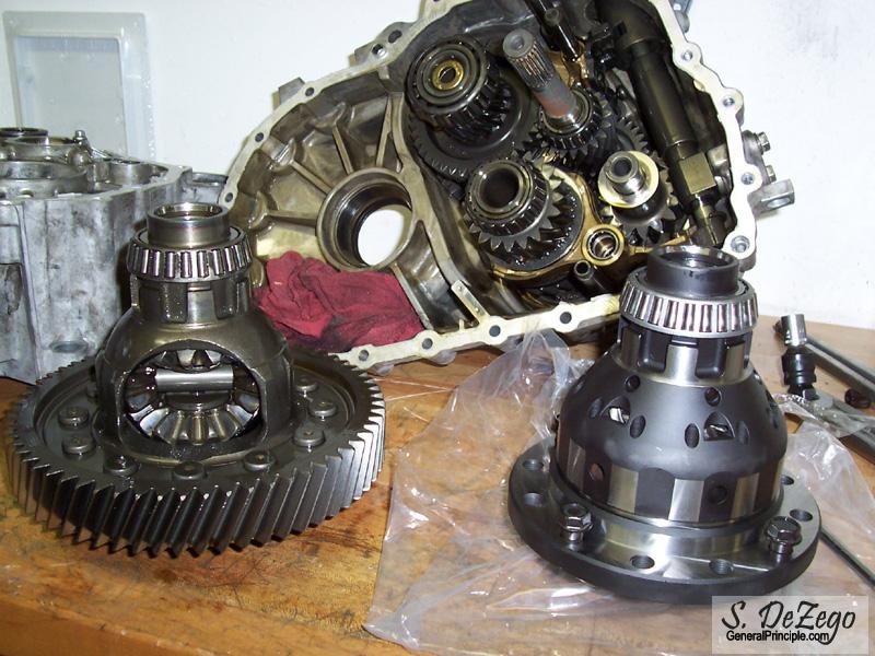
Removing the Ring Gear
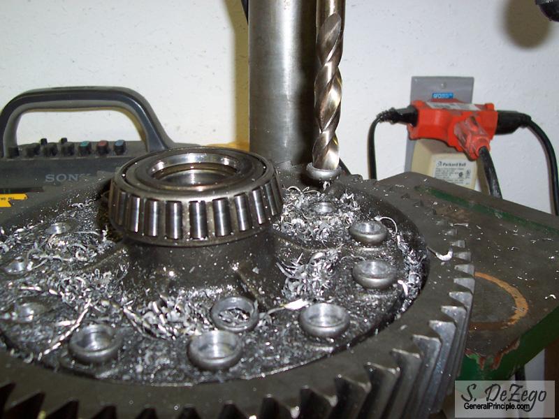
I find it easier just to press the remaining rivets out
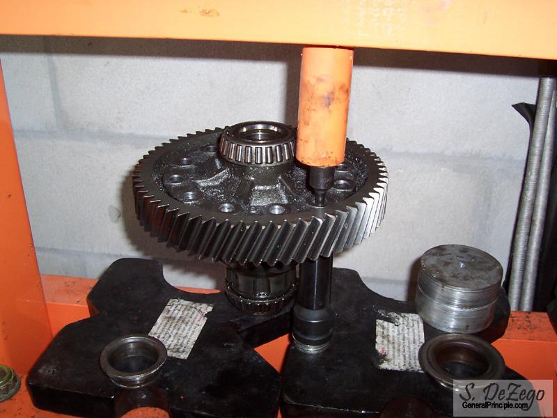
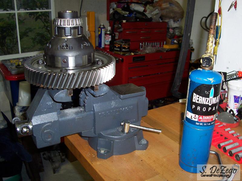
Heat up the ring gear and use the supplied 4 bolts to pull the ring gear on
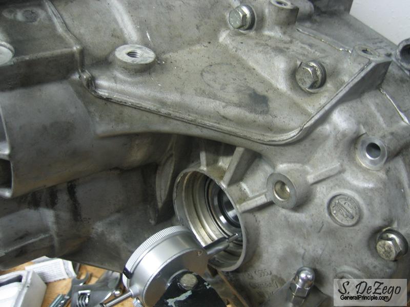
Checking the Shimming on the diff.
Install the new race with the factory shim on the trans case side. Install the Race ONLY on the Bell side and measure the end play. Then add .3mm for preload and that is the shim you need. I ended up needing a 1.05mm shim.
December 01, 2007
Fair question actually and here are the reasons:
Stock forged VW rods are proven to easily handle 300hp-350+ reliably and the ABA rods are among the strongest (no wimpy 19mm pins like a lot of 1.8ts). My rods were resized and shot peened which is proven to add up to 20% to the strength of rods. Power goals here are modest. This is not a Big Turbo motor and the G60 itself is somewhat limiting for big hp numbers. So, goals here are estimated in the 250hp range, but that will ultimately depend on how many rpm I can turn (again limited by the G60). ...but, wait until you see the torque curve and area under it as t will be a monster to drive
When I was planning and starting machine work, etc, SCAT rods were really just making their way out and becoming widespread for h2o VWs. The only options were $600-700+ Pauter, etc. In retrospect, I have about 250 in these rods with Resizing, Shot peen and ARP bolts, so now it wouldn't make sense not to go with SCATS, IE, etc.
One thing I really like about the factory rods is that they are rifle drilled, which does have it's benefits. Again, hp dictates what makes sense and money is always an object.
My patience has been getting a little thin lately as I watch others who started way after mine, finish way before mine. This project has taken much longer than expected, mainly due to my time and well $$. Also, this is definitely a one of a kind and required a lot of one off machine work as you will see soon with forthcoming updates. We are closing in though!
Shawn
December 20, 2007
his progress update will not be all that exciting, but it is progress for issues that needed to be resolved.
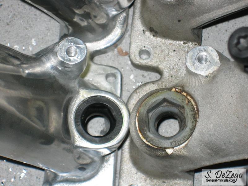
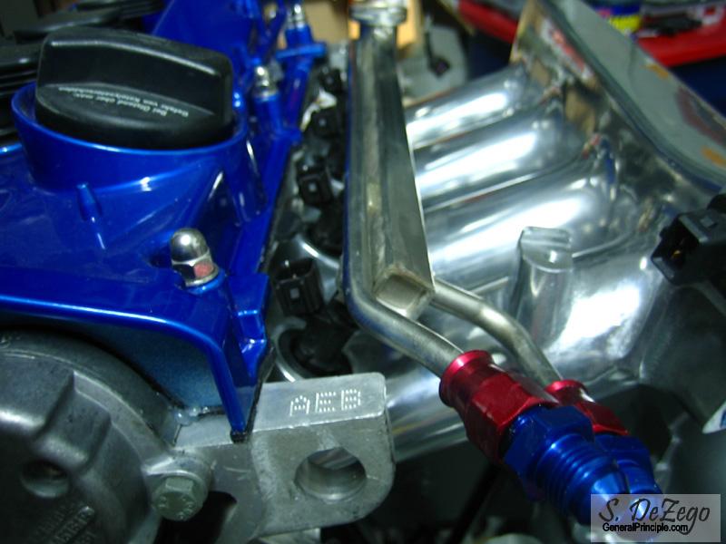
1.) I was not happy with the stock barb connections on the fuel rail
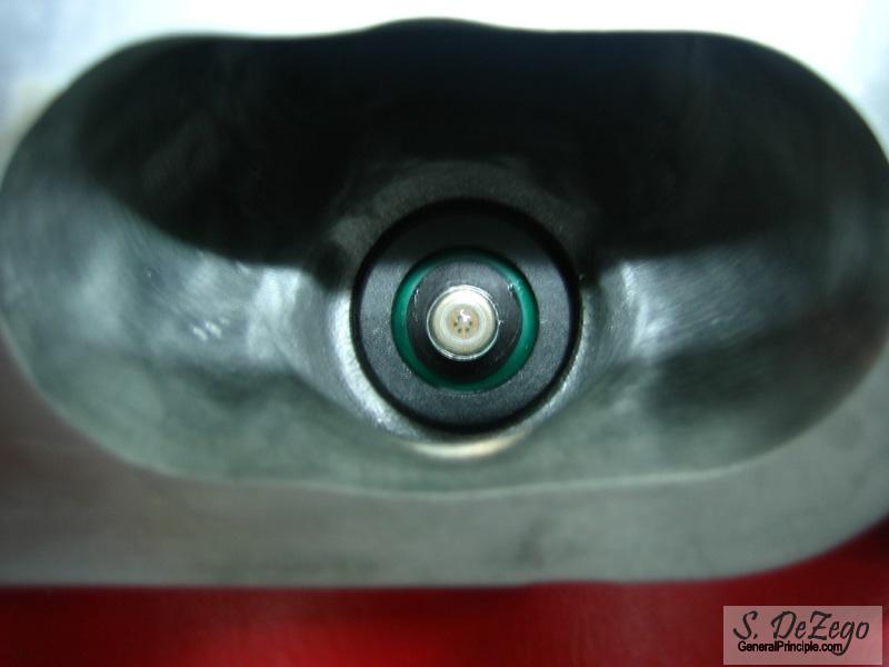
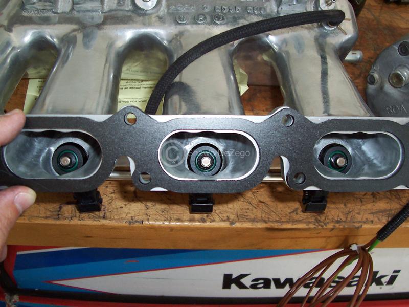
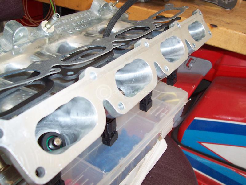
2.) The AEB and Euro AGU both came with the early garden variety Bosch EV1 Injectors. To upgrade to the later (much better) Bosch EV6, you would need to either get a custom rail made, manifold or do what I did.
The pics tell the story.
First I cut the barbs off of the rails.
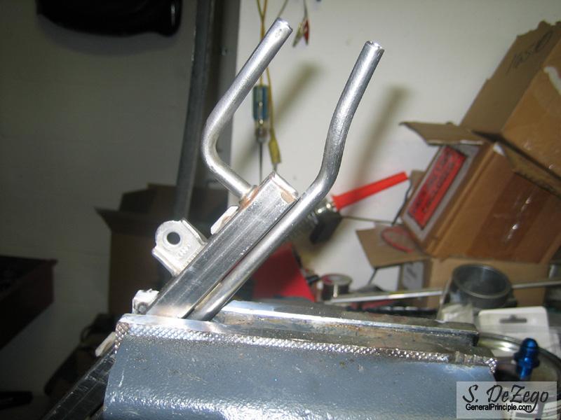
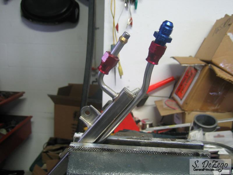
Then I inserted the rear compression fitting along with the brass ferrell onto the pipe. I flared the end of the pipe so that the fittings could NEVER come apart.
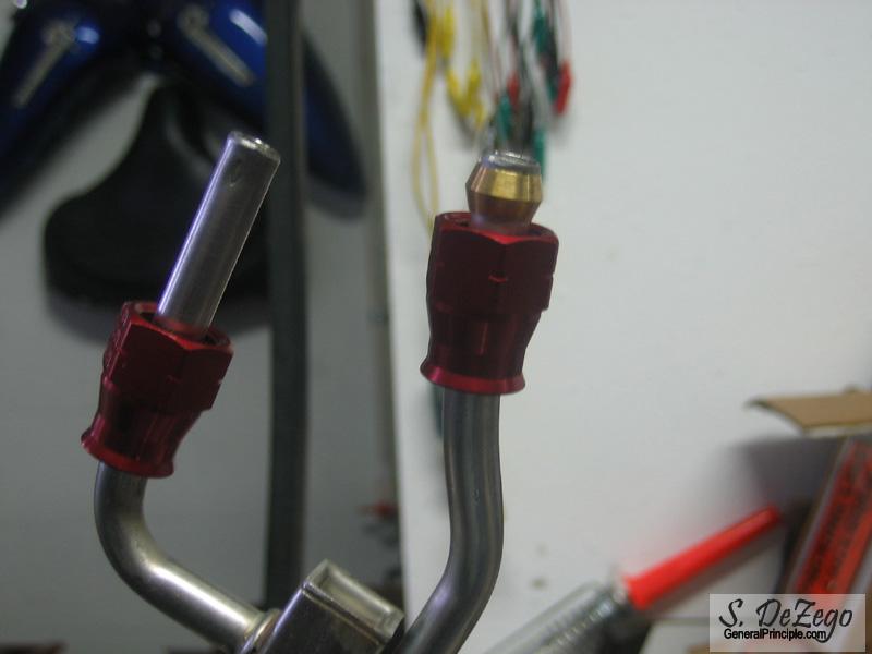
I then cleaned and used Red Loctite on the pipe and Ferrell for piece of mind.
...Injectors mods to the manifold mentioned above
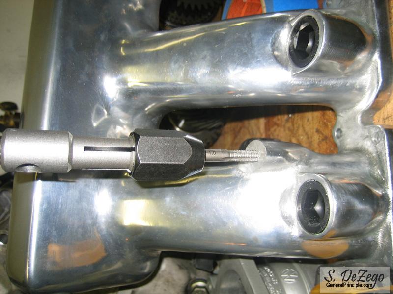
The only thing to note is that the rail bosses, must be carefully drilled deeper and then tapped so that a decent length bolt can still be used. I went ~ the distance that was cut off (12.75mm or .5") w/o any issue.
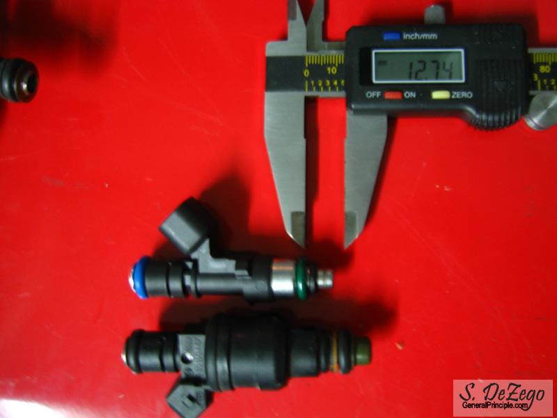
Euro AGU big port mani next to the AWP.
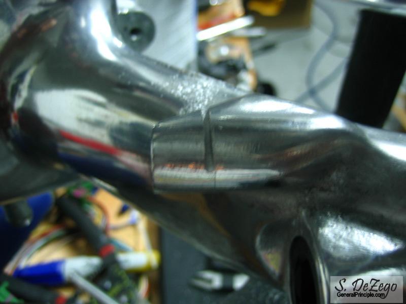
After cutting them both .5" and cleaning them up with a flat AL rasp
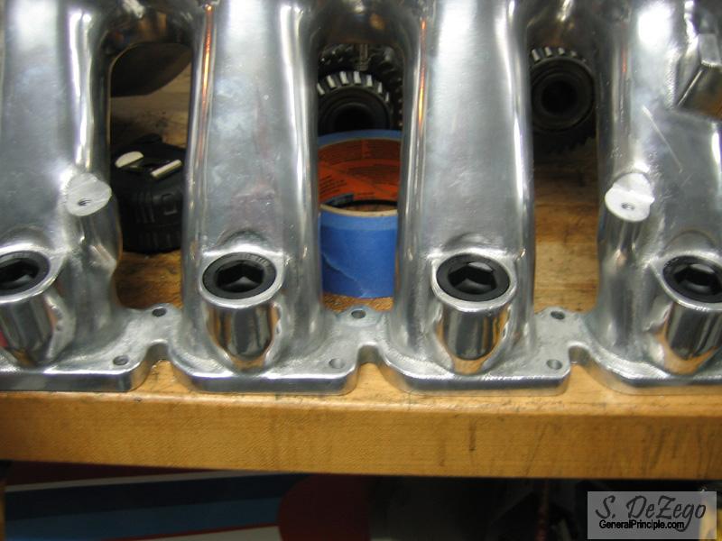
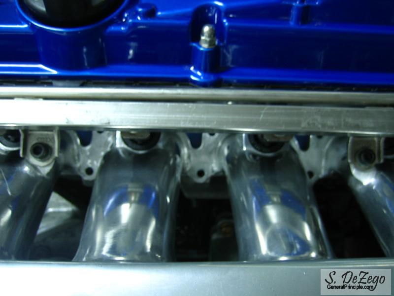
Exactly like the EV1s fit
easer pic
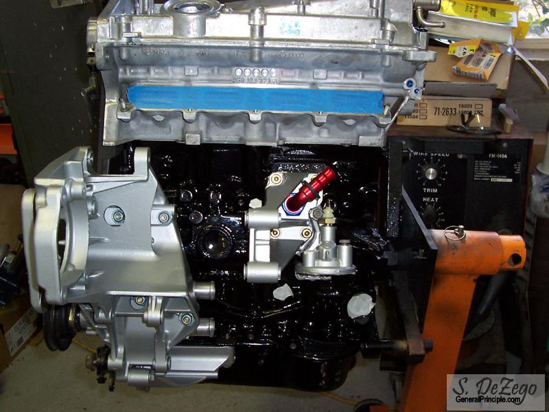
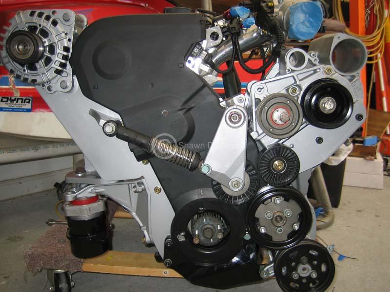
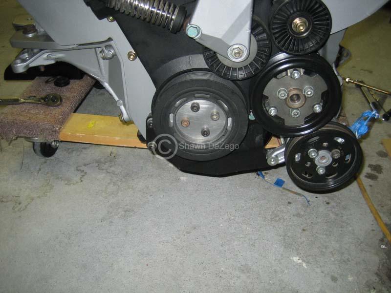
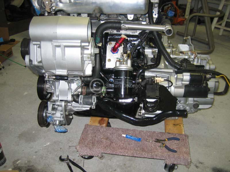
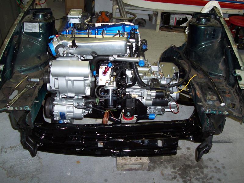
Here it is: Serpentine belt to drive all accessories and no V belt. Note, this same setup could be used w/o Power steering and/or A/C (which would certainly simplify things).
Everything is fabricated so what you see is "ready to run"! I just need to take it back down, pretty up all the brackets a bit and paint them. Needless to say, the development and creation of this setup was a painstakingly long process. I can't begin to tell you how much time I have in it is hard to see all of the custom mounts in this pic Everything was carefully and methodically done the way you see it, so if you have any questions on why I did something feel free to ask.
All I ask, is that if you copy the setup, you give me proper credits
Shawn
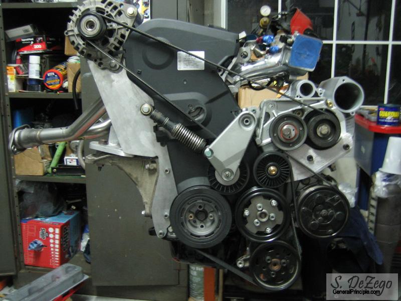
Here is a rundown of the setup:
- Late 1.8t 120A Alt with decoupling (clutched pulley)
- 1.8t PS pump and pulley
- Custom PS pump mount/setup
- Mk3 rear Engine Bracket (could use the G60 3 bolt if you wanted)
- Rear Alt/Engine brkt with rear spine and additional support mount to Engine brkt.
- Top Alt bracket
- Custom Tensioner mount (tensioner shock, roller, brkt arm and pin are stock G60)
- Custom Relay Roller and bracket (and modified G60 bracket).
- 8v Cam belt tensioner
- Serp belt of undisclosed length
- G60 non-A/C ribbed waterpump pulley
March 04, 2008
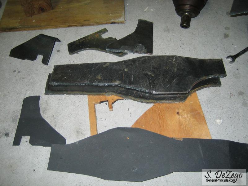
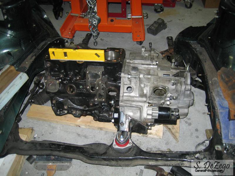
Progress has been slow, but I should have a few update pics coming up of the Mock engine and trans in mock engine bay. ...making of the mounts.
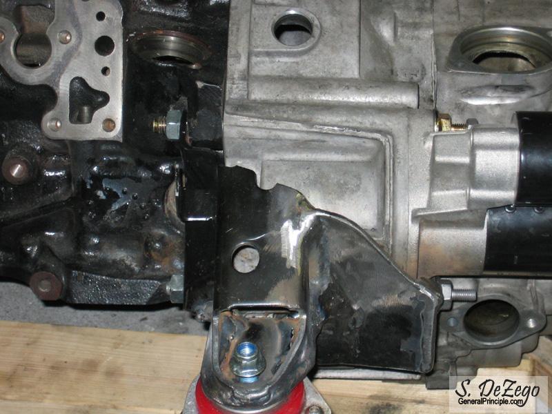
I found and received the correct bolt/studs for the 02m Starter as the factory ones were too short for the 8v Block. I also had to order the Mk3 Front engine brkt for use on the Vr front carrier. I still need to modify it, but the G60/Mk2 brkt will not work because of the mount face angle etc. I wanted to make sure the engine was tip top in the factory spot before I start fabbing the 02m rear Trans mount.
Shawn
March 12, 2008
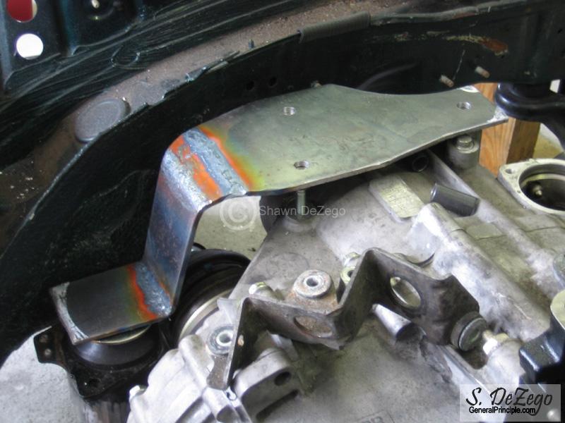
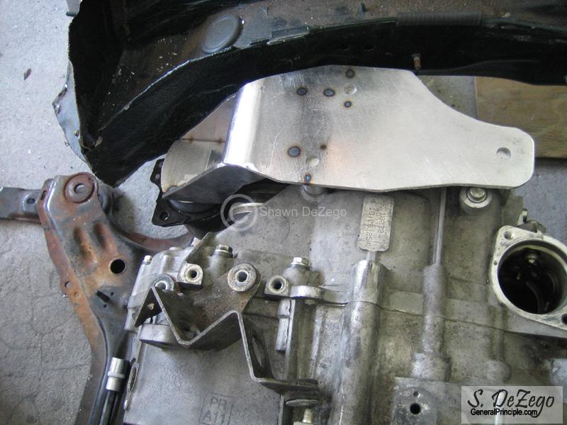
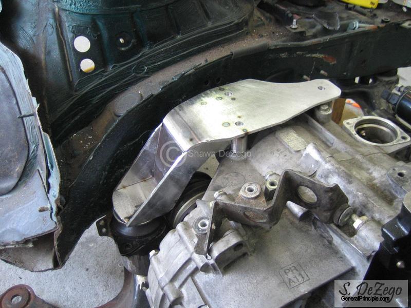
As mentioned I had 2 snags before being able to start making the 02m Rear Mount
- 1.) The 02m Starter Bolts were way too short to make it though the starter and 058 block and leave enough room for the mount and nuts
- 2.) The G60 (mk2 4cyl) front engine brkt will not work using the Vr front engine carrier even when using the proper engine mount. Not that I could't re-make a whole new mount, but I wanted the engine/trans positioned in the stock location FIRST, before fabbing the rear trans mount.
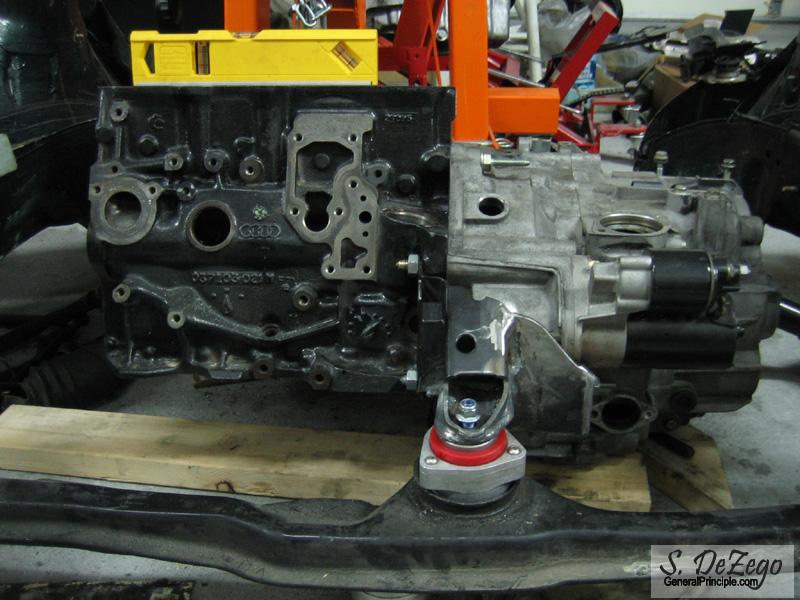
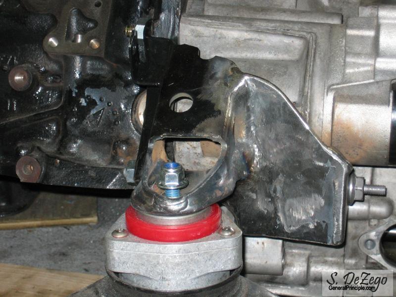
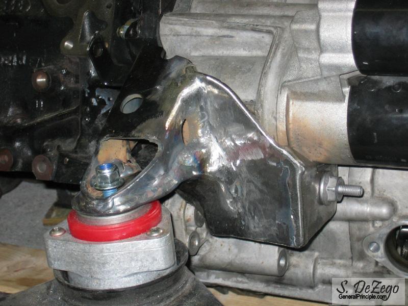
I found (after a LOT of searching) the perfect studs for the starter, and after ordering a new Mk3 4 cyl front engine brkt, it proved to be the ticked to get everything as situated. It is very stout and I will likely just add a triangular mount point to the lower starter stud.
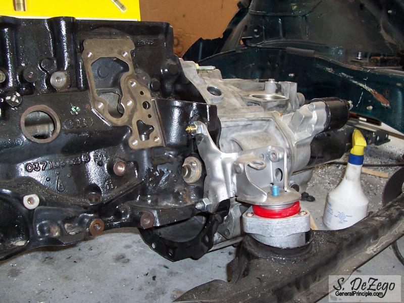
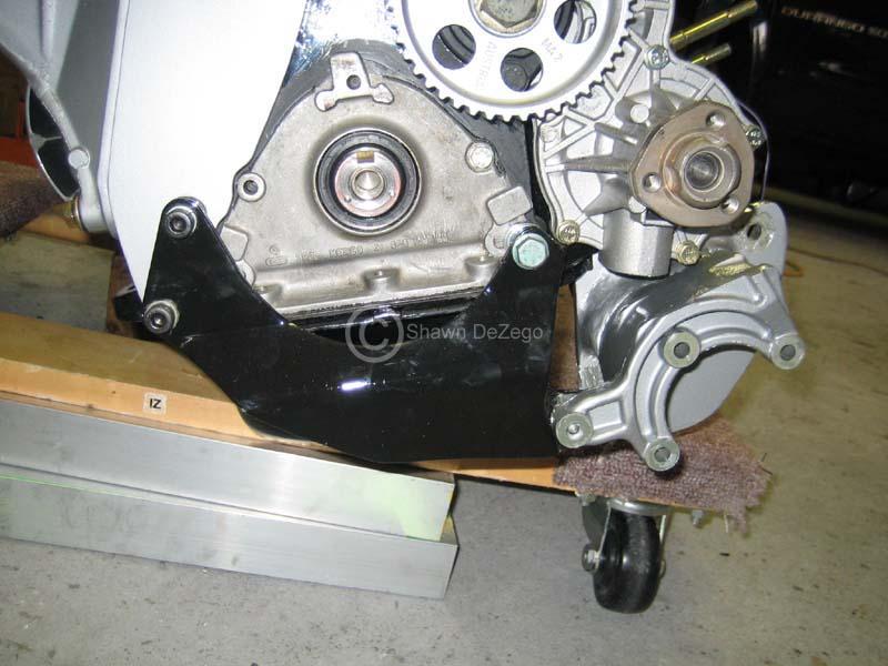
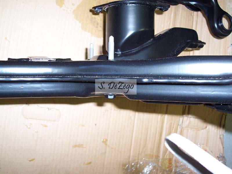
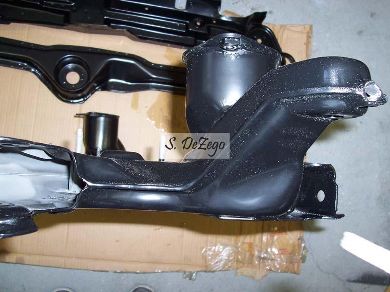
Shows the problem using the G60/Mk2 Engine brkt with the Vr carrier/mount
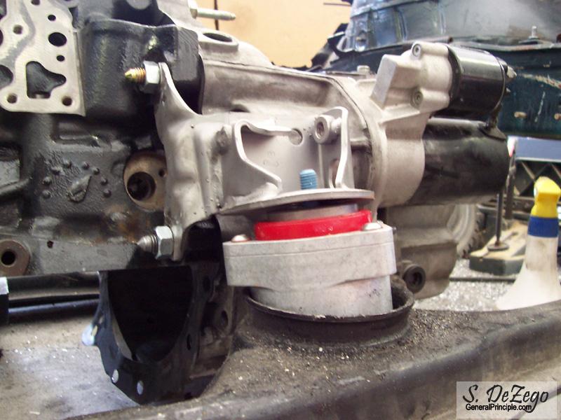
Now, using the Mk3 4cyl Engine brkt
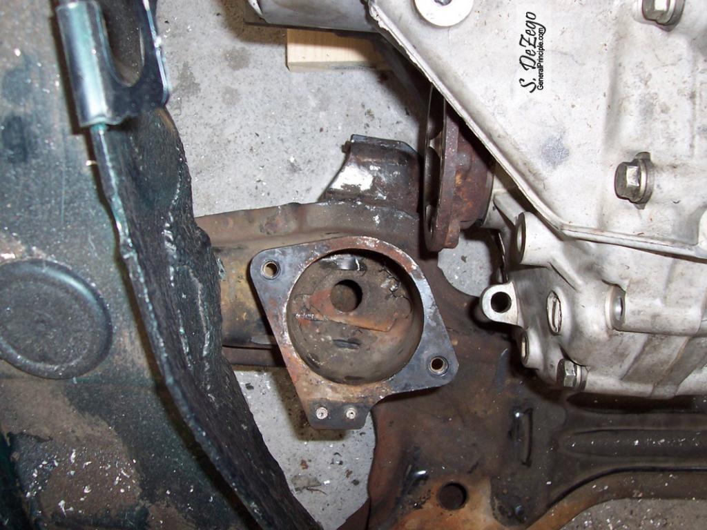
...and for the naysayers that you can properly mount the 02m w/o moving the rear trans Subframe mount cup, sorry, but you are wrong. The Cup MUST be moved back (1/4-1/2") to clear the CV or else your engine will have to be cocked.
May 01, 2008
small update. Baseball season is almost over, so I should have some free time again.
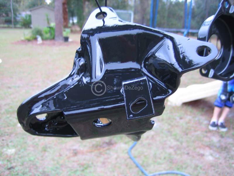
Front motor mount is done (sans clean up and powder coat). Should be strong enough
waterJet > Plasma but unfortunately, I have neither. I went to my neighbor's house and I have a feeling that he does not really know how to use his plasma cutter. Not very clean cuts as I expected, but that just adds a little grinding time.
May 01, 2008
...patiently awaiting. Been driving it a lot lately with gas prices.
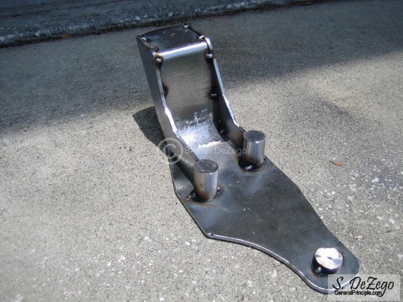
June 16, 2008
..been making some progress and have the trans mount about 75% done. Making 2 just for giggles.
I'll get some more pics up soon.
I spent a few days on a detour and made up a nice box tucked in the drivers rear hatch side for my 10" sub and got rid of the 6x9 in the parcel. Sounds real nice and looks much cleaner
June 17, 2008
Running the ERR code box. I have the ratios here somewhere, but can't locate them right now. It was out of an '03 Beetle Turbo S.
I am running 17's, but currently 40series tires (+2). I may have to make some tweaks to get things exactly how I want them. I need to do some gearing calcs first and I have not done that to date.
June 18, 2008
Thanks, and I guess you did have some spare time, LOL Yea, those are the gearing specs for the ERR.
After you inquired, it did give me some ambition last night to dig out my specs. I also did a but of searching and found this thread:
http://forums.vwvortex.com/showthread.php?3706971
There is some really good info in there as well as the Excel spreadsheets that the one guy posted .
I had written a gear and shift calculator program years ago, but these put it to shame
When I get some time I will plot out some data of the 02m vs the ATA (02a) that is in there now. Ideally, it would be good to have a bit bigger tire or a slightly taller R&P, but in looking at the data, it is still not as bad as the current 02a (1st and second).
As far as the pulley, I have measured belts and tensioner mount points for the 68 and the stock pulley. I want to rev to at least 6500, so that is pushing the 68 but the charger has the uprated timer bearings and such. I just don't like pressing my luck even though there are some folks really revving the G60. Again, I don't see myself spending much time up that high anyway, except maybe for some Dynos and some occasional trips to the strip (which I rarely if ever do).
Shawn
June 23, 2008
Update:
Trans/motor mounts are complete!! I don;t have a pic of the final mount Tig'ed up, but it is all done. I also added a side brace to the rear trans mount for overkill. I will get a pic of the completed mount.
I cur off the alignment nibs off of the trans mount as they just got in the way. I also needed to grind the side of it that faces the D/S inner CV as well as the subframe cup as illustrated above (even with relocating the cup). This just gives better clearance and I have about 1/2" clearance or more between the mounts and the 02m CV.
October 22, 2008
thanks. Most of what I have in my garage are just extensive Hand tools and such.
I do have a 20T Press, Cherry Picker, Med size drill press, Miller 25dx TIG, a Snap on MIG, chop saw and torches.
For anything else, I go up to my brothers/our Harley shop. Not an extensive machine shop, but a small lathe, center hone, Beab blaster, etc. We did just get a Gen II bridgeport though
I took the old Benchmaster Mill home, but have yet to have the time to get it setup.
My project has crept very slowly. Too busy at work, other projects, Coaching and wife/kids. I hope to get back into full gear here soon.
November 20, 2009
Outside of gathering a bunch of parts and such, progress has been slow up until a couple of weeks ago and I got quite a few things done. It took a request to make one of my 02M mounts for a friend to really get me motivated
- I seam welded my KFrame and shortened the Mk3 Rear legs for the Corrado - Sry, No Pics ATM
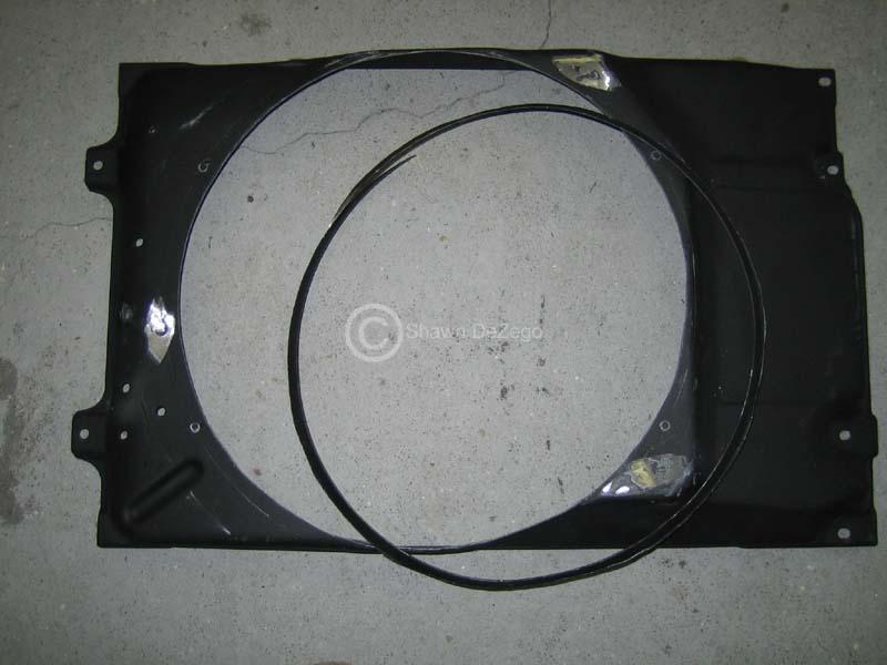
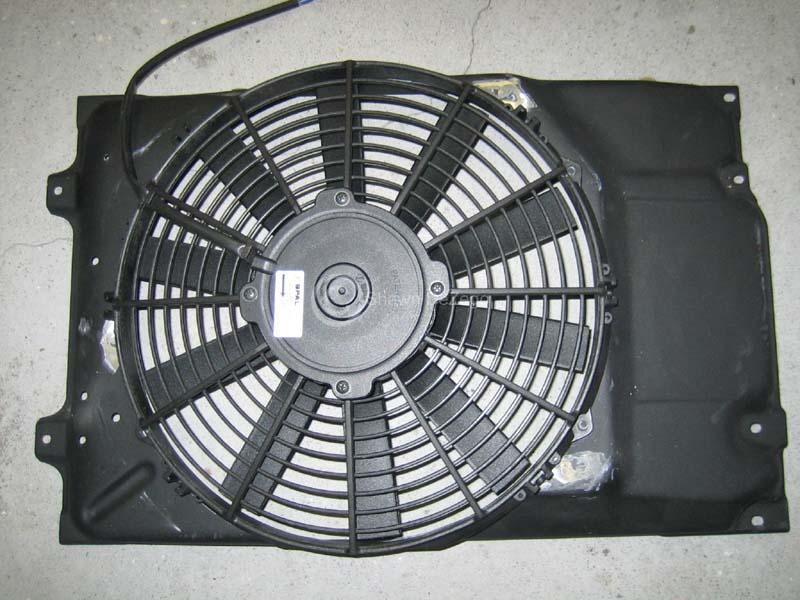
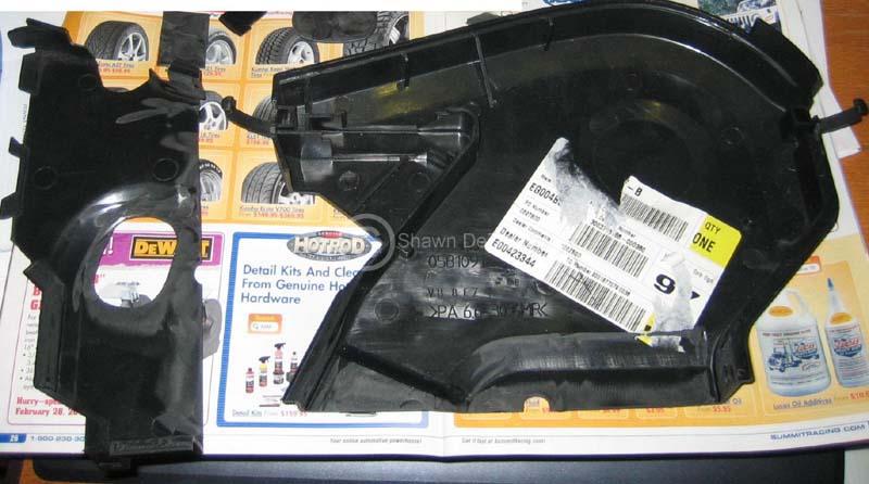
- Modified my Fan shroud for the SPAL
- Finished up all Engine brkets
- Got stuff ready to sandblast and paint
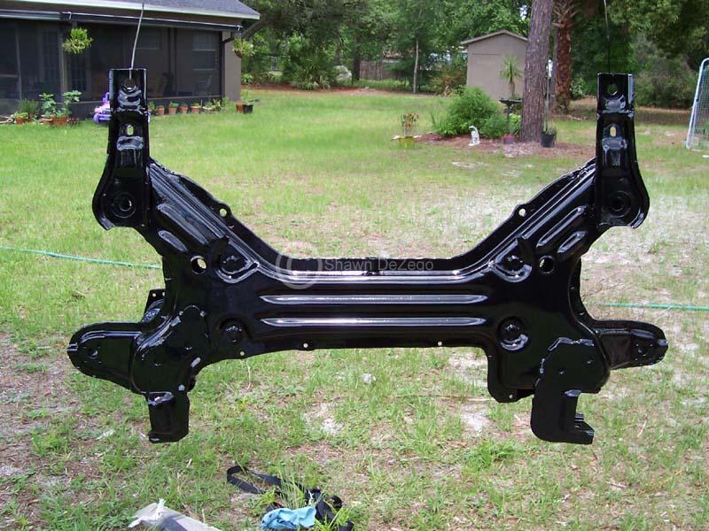
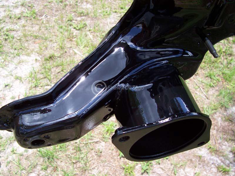
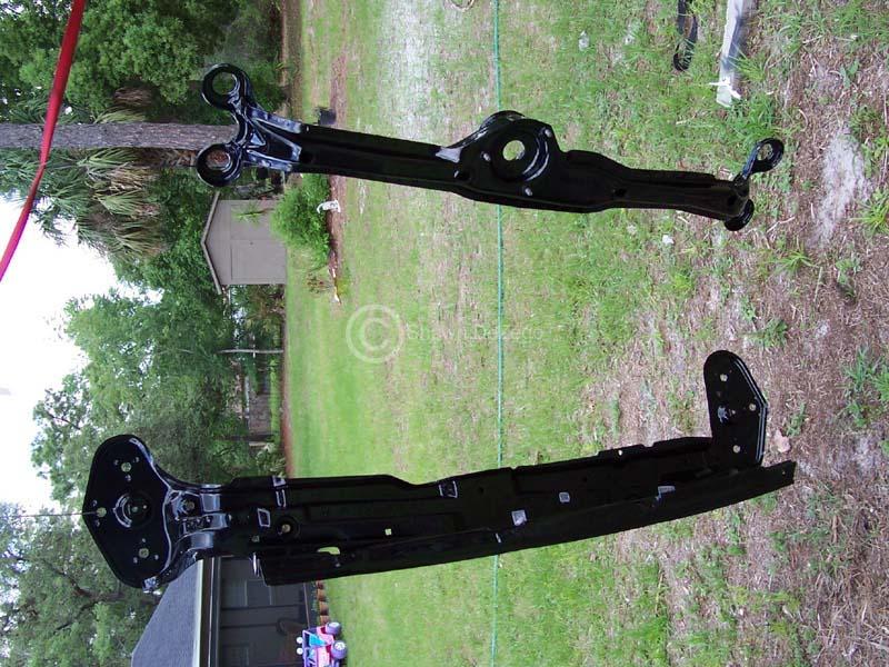
- KFrame
- Entire ft Vr suspension
- Vr Ft Engine carrier
- new Lower Rad support
- All custom engine brackets and mounts
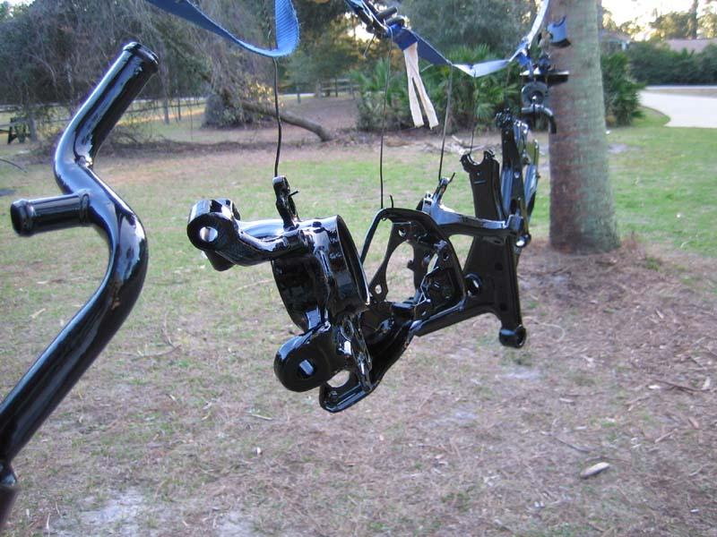
Pics of 02m Mount:
Modified Fan Shroud for SPAL (idea from Frank aka G60ing)
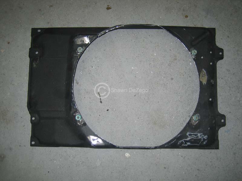
With Studs welded on
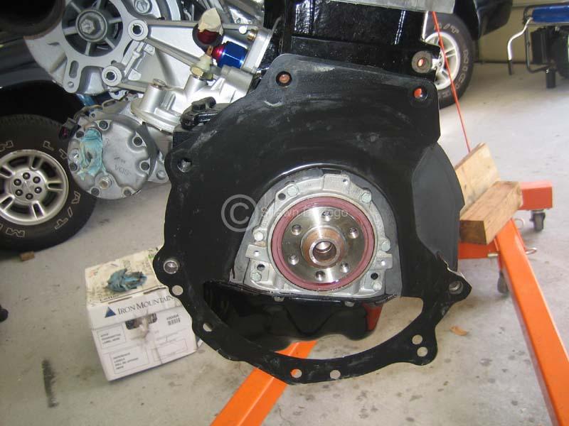
Flywheel and clutch install. I have a template to make the lower trans dust shield, since the Mk4 oil pan bolts to the Trans. I guess if I had a Schrick oil pan, I would weld tabs for the trans.
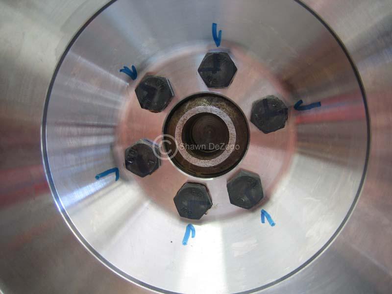
VW Lug wrench comes through again for clutch lineup on the 02m, with a couple of wraps of metal tape
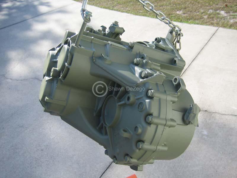
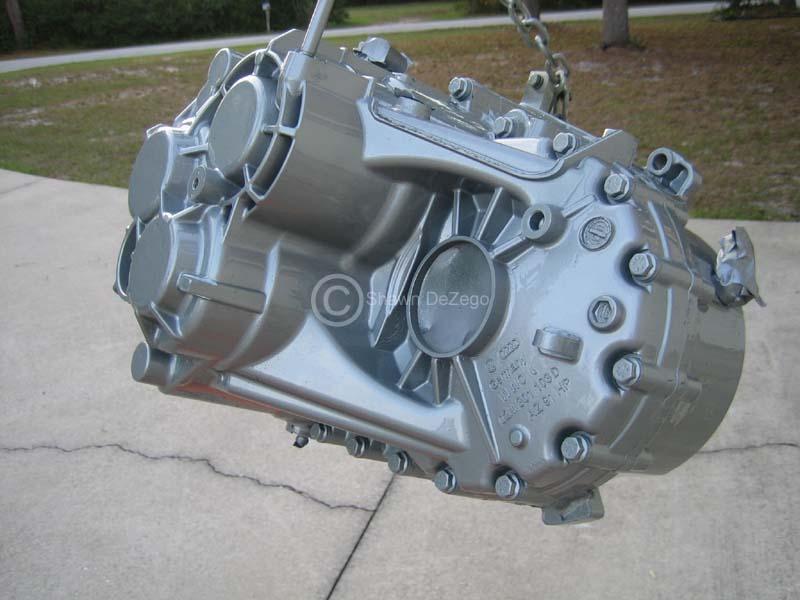
Final Trans assembly with peloquin and paint.
Proper Diff Preload shim installed
Self Etching Primer
November 23, 2009
My daughter doubled in age since I started this project, LOL
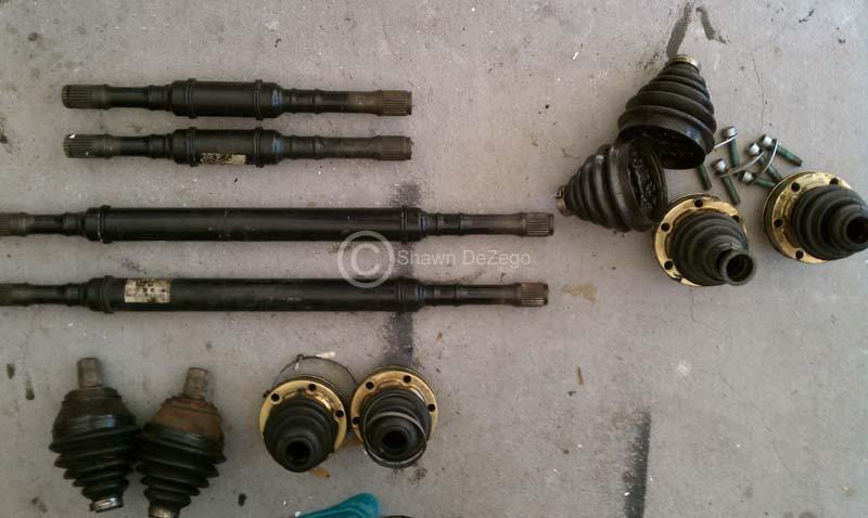
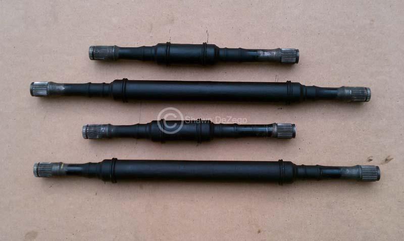
I am working on the axle lengths (remember I am switching to the + suspension).
There is a lot of ambiguity in this regard, so I took my own measurements and calculations. I may wait until I get my subframe, control arms, etc finished and bolt everything together to measure the distances from the Trans Flanges to the wheel hub inner flanges. Here is a thread I have added info to -> http://forums.vwvortex.com/showthread.php?3610564, but I will post the specifics here.
Measurements from Bellhousing Face to CV Flange:
02a - (NOTE: 3mm CV flange Recess taken into account)
D/S --------------- P/S
206.55mm ------ 37.7mm
Total Diff Width -Flange to Flange = 244.25mm
02m
D/S ---------- P/S
242.24mm ------ 57.8mm
Total Diff Width -Flange to Flange = 300.04mm
Total Diff Width Differences and thus net axle length difference = 55.79mm (2.2")
Based on each Flange Measurements:
02m D/S Axle = -20.1mm (-.79")
02m P/S Axle = -35.69mm (-1.41")
These measurements, I am pretty confident with. The tricky part is measuring the axle lengths in comparison, since the inner CV's can move in and out and throw off measurements as well as the fact that 02m inner CV are Tripods, so a direct comparison is a bit difficult to be precise.
Here is what I have for axle measurements (Flange to Bearing)
Stock Corrado Vr (+ suspension):
27 7/8" - 18 5/8"
Calculated Lengths using my above calcs based on Vr + axles:
27" and 17 1/4"
Nate's Reported Measurements:
26 13/16" and 16 1/2"
Blk95VR6 (verifying):
27 5/16" and 16 3/4"
Rycou (DSS axles) (just purchased and just measured):
26 7/8" and 17 5/8"
--------------
So, I am pretty confident that ~27" on the P/S Axle is correct.
But, you can see the discrepancies on the D/S axle. I can easily see that a measurement can be 1/4" off due to the inner CV position, but this is more.
FWIW my stock Beetle Turbo S short axle is 17 3/8" which is pretty darn close if not usable as is. P/S is 28 5/8", so it def needs to be shortened.
Thanks, that is pretty close to my calcs above (1.41" and .79").
Regardless whether it is plus or non-plus, the amount the axles must be shortened will be the same. The final lengths (plus or non-plus) will obviously be different.
Yea, I will probably wait until the last minute to shorten them and measure the actual axle length need (Flange to bearing) with the car's weight on the suspension.
Lowering the car will definitely change things slightly and I know that being "EXACT" not that critical as there is room for forgiveness with the inner CV.
December 07, 2009
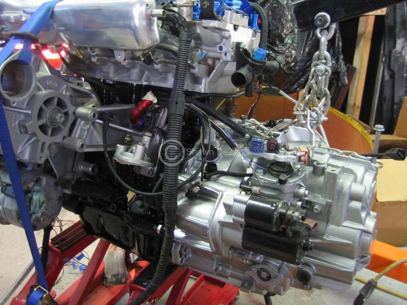
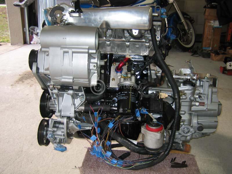
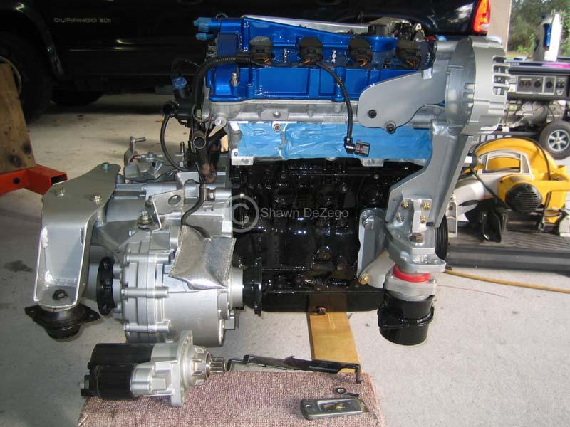
Motor and Trans are one.
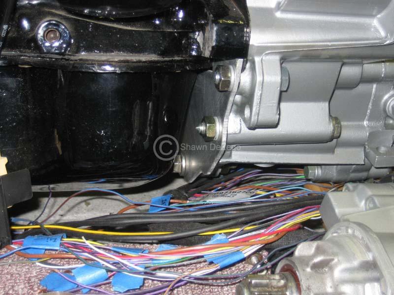
Started on the wiring too. I acquired a brand new AWP harness with my orig trade/swap and this harness is about 80% of what I need for megasquirt, so I don't have to build from scratch. I felt kind of dirt though cutting off the factory ECu plugs-
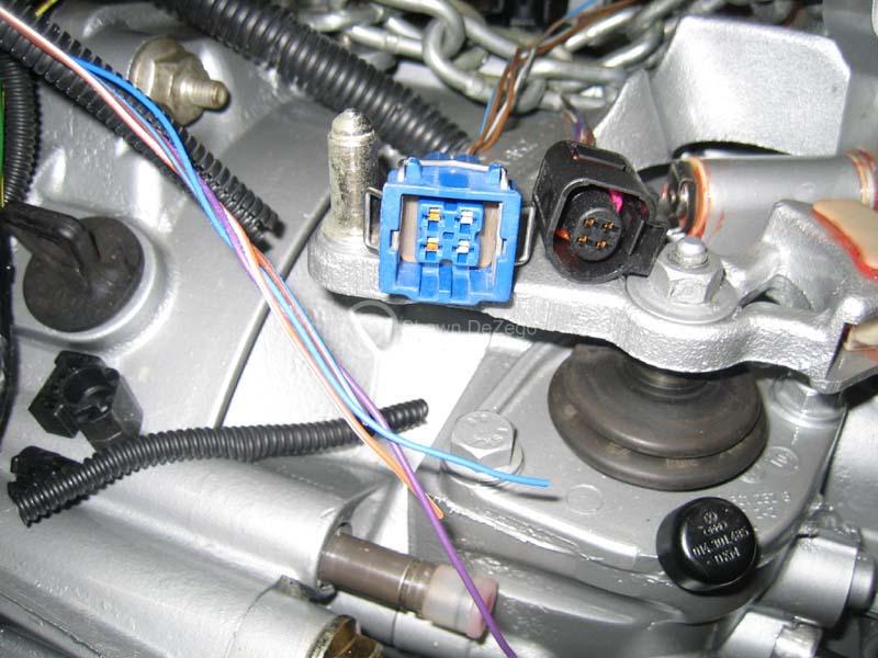
The factory convoluted tubing and connectors are not my favorite, but since I am using a lot of the harness in tact, I am fine with it.
Here is a sample of one of the plugs that needed to be changed. Since the pin sizes were different for the 2 coolant plugs, I could not just repin to the new housing.
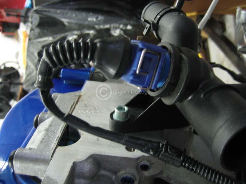
Shiny stuff
December 14, 2009
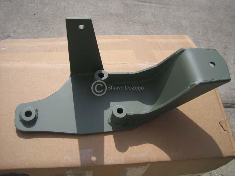
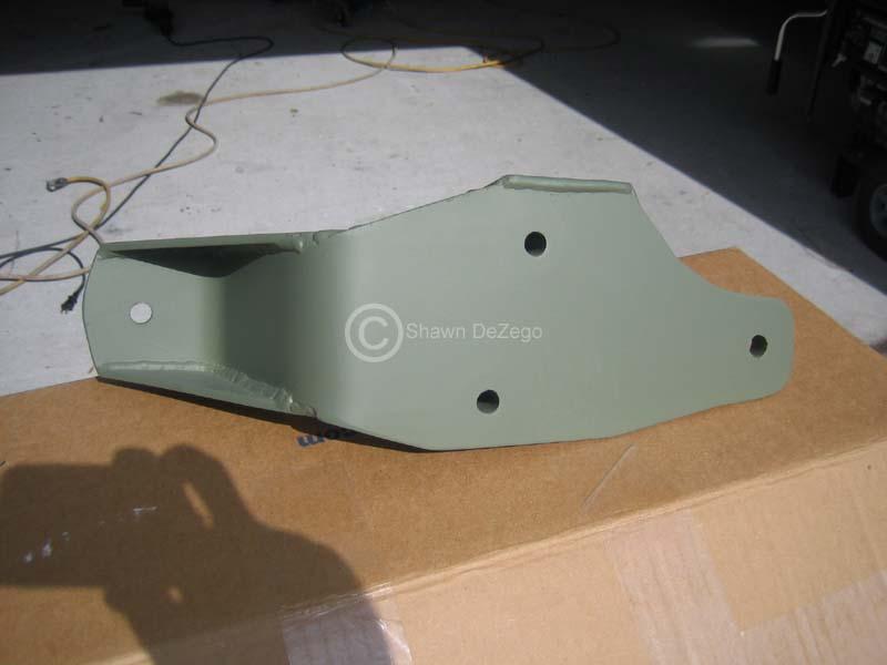
Some pics showing a lot of the custom brackerty I made. Most of which will be completely hidden so I am not sure why I spent so much time prepping and painting (outside of the rear alt mount setup).
Custom front support for custom Mk4 PS brkt to run all on serpentine belt
Custom Rear mount Mk4 Alt support
Custom brkt for using G60 Serp tensioner arm in my single belt setup
Front view of above
Side view of PS mount
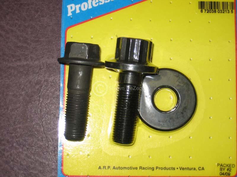
Also, The crank bolt was never installed yet as I was trying to decide whether to use the 6pt or 12 pt 16v crank bolt. After researching and acquiring both, the 6pt is actually 10.9 grade and the 12 pt is 8.8.
Anyone who knows the 058 block/crank knows the bolt is always a problem and especially so on the G60, which is the reason for my over obsession. There is a bit more at stake here than on the non-interference 8v.
Anyway, after searching, I just found what I think may be an ARP solution from a completely different application. Even though my cog is pinned (earlier in this thread), extra insurance is never a bad thing. ...granted a $35 extra insurance
I will post up the details when the ARP hardware arrives in the next 7-10 days.
January 07, 2010
Crank Bolt Dilemma solved:
We all know the 058 block/crank bolt fails, so In my over-obsession I was searching on the best bolt to use for this motor, since there is a lot at stake.
You may know that VW used two different bolts over the years on 16v's (possibly 3 if you look in the Bentley, but I will ignore since I have no info on the 3rd other than torque specs). There was a 6pt bolt which was 46mm in length and used a 7mm thick washer, and the later 12 pt bolt which was 39mm and used no washer.
I bought them both from VW and here are some facts:
- Thread and pitch are 14mm x 1.5
- The 6pt is 10.9 grade @ 46mm
- The 12 pt is 8.8 grade @ 39mm
- 8vs are 10.9 FYI and shorter of course @ 33mm
- Diesels and 06a blocks use a larger diameter bolt (16mm and ARP now makes a solution).
Note: (46mm 6pt bolt - 7mm washer = 39mm 12pt)
Here are the tq specs:
So, I started searching high and low for a hardened Stud and aircraft style nut, but was hard at finding what I wanted. I started looking through ARP's catalog to cross reference something and much to my surprise, I found two ARP possibilities.
1.) Mitsu - 2L (4G63) - 14mx1.5 x 1.525" (38.7mm) - ARP#207-2501
2.) Ford Duratec (1.8 & 2L) - - 14mx1.5 x 1.735" (44.1mm) - ARP#251-2501
They both come with a hardened 1/4" (6.35mm) washer which we would not use in either case because it is too large in diam.
So, I ordered #2 becuase it is longer (much like the PL bolt and I figured I could use some std hardened washer to take up some of the length and still end up with more thread bite in the crank. Note: The 6pt 46mm factory bolt is just about 1-2mm too long w/o using the 7mm washer and just starts to bottom out in the ABA crank as it makes contact, but could vary from crank to crank.
So, you can see that #2 above looks like it is a pretty darn good match when using the washer (and poss #1 if w/o the washer if the shoulder is large enough).
--------------------------->
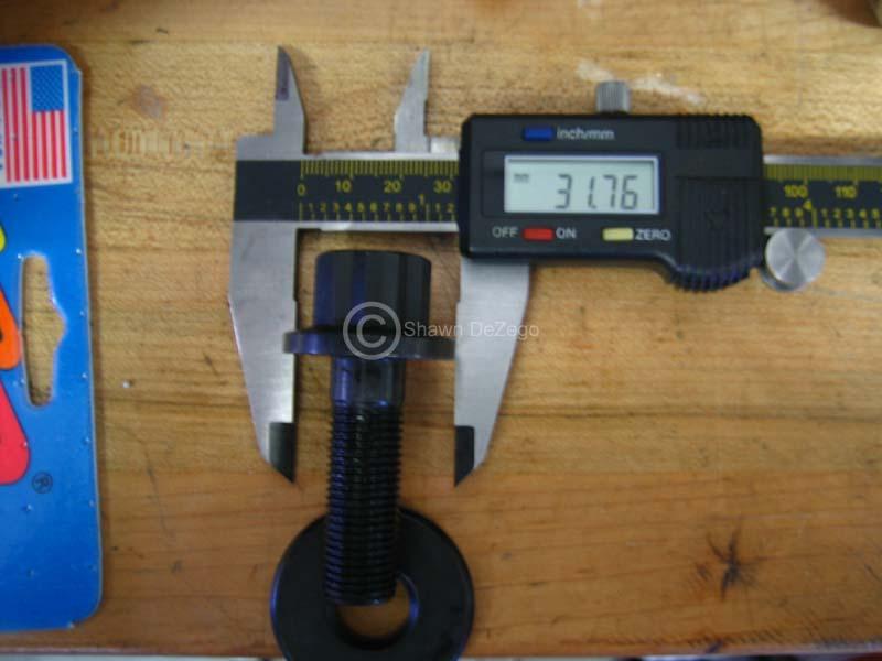
I received the bolt and here are the deets.
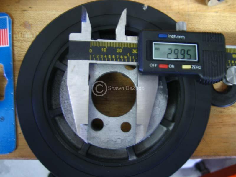
Perfect length, perfect thread, but the head was unfortunately too big. Now, this could still be used as is, but you would have no way of getting the harmonic balancer on/off (not too good). So, I went up to the shop and threw it up on the lathe to trim the bolt head down a tad so that it fits through the Balancer hole.
Looks like it is now a winner. You can either use the thick stock 6 sided 16v washer with it, or get a thinner 14mm one from the hardware store which is what I did. This will actually give more threads to the crank which was no prob for my ABA crank.
Pics:
in comparison to the stock PL 6 sided bolts that uses the thick washer
Head a tad too big
Shaved a tad down on the lathe
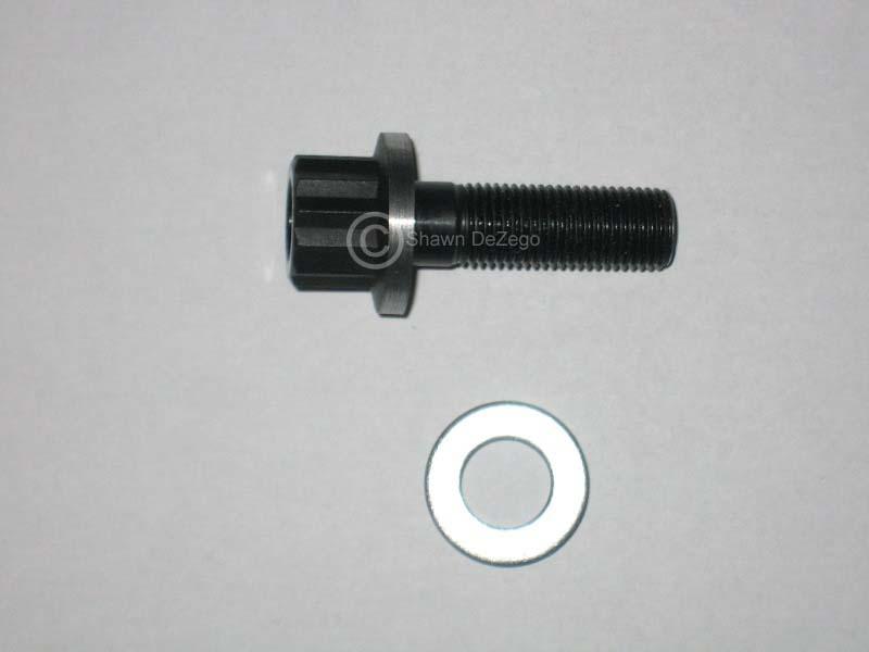
Did someone say OCD?
Also, for reference:
ARP bolts are 200,000 PSI bolts which puts them at a 12.9 hardness and is impossible to find our size bolt in that spec. I wasn't even able to source a 10.9 bolt outside of the factory VW in a few hours of searching.
Also, if you are the engineering type and care to compare bolt strengths, here you go:
http://www.boltdepot.com/fastener-in...ade-Chart.aspx
Couple of fairly recent pics of some stuff I am working on.
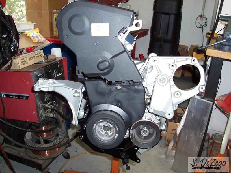
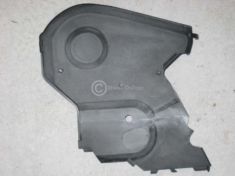
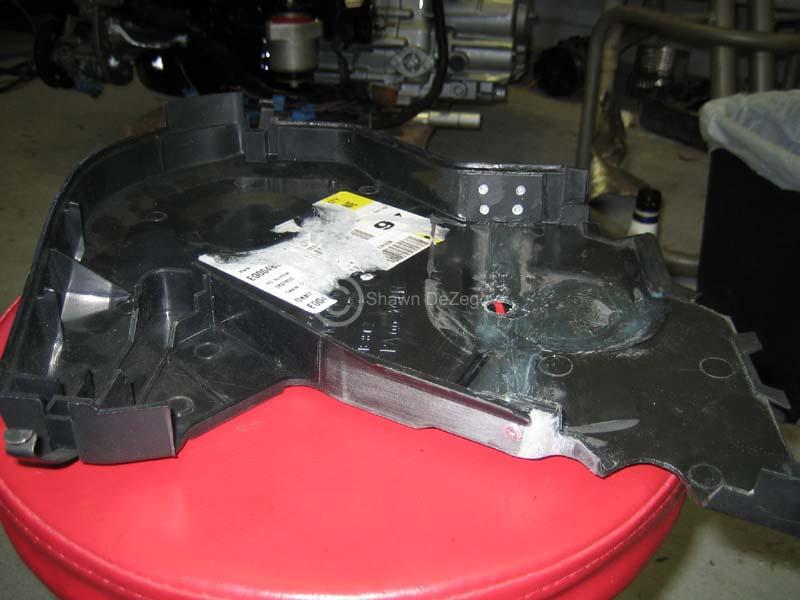
- Making a timing belt cover to account for the tall ABA block (not finished in the pics) out of a few AEB ones.
- Starting to organize the harness
- Started making the custom coolant hard pipes
- Bolting some more stuff on for good
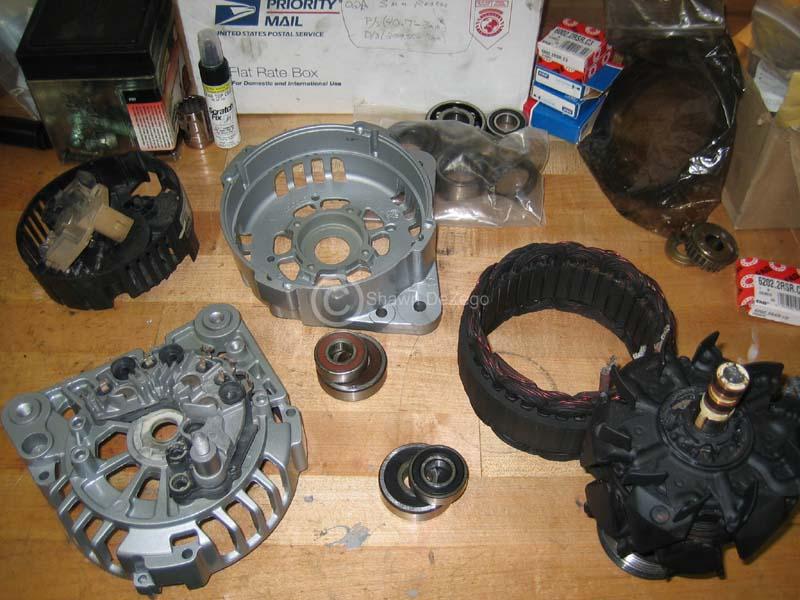
Also, rebuilt my 1.8t 120 Amp Alt. No finished pic, but it is done.
January 14, 2010
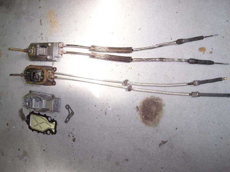
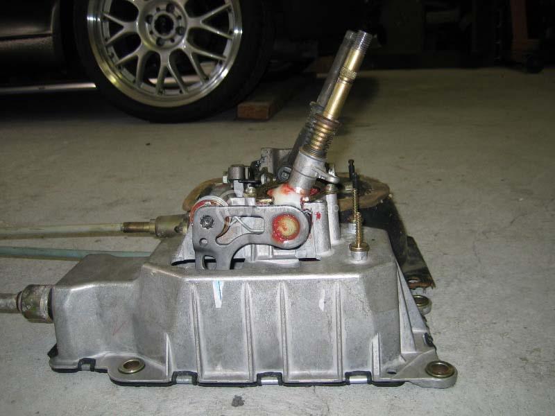
Adding the Euro Shifter information here. For those who are unaware, there is a Euro Lupo that uses the 02m/02j shift mechanism in a box that fits 02a tunnels.
The Following 3 parts are needed to convert.
ETKA shows these to cross ref to:
CA '96-'03 Caddy
LU '99-'03 Lupo / Lupo 3L TDi
LU '04-'06 Lupo / Lupo 3L TDi
PO '95-'00 Polo / Derby
PO '00-'02 Polo / Derby
POC '00-'02 Polo Classic / Variant
I should also give credit to the thread that I first saw them in -> http://forums.vwvortex.com/showthread.php?4306052
Here is is from my research thread ->http://forums.vwvortex.com/showthread.php?4668026/page1
This stuff is well worth the price to have an OEM solution. I am sure we can all fab up the parts and hack up our tunnel to make the 02m box fit in, but I would much rather spend my time on other more valuable areas.
I swapped out the parts this afternoon and it was simple and straightforward.
NOTE: The 02m stick is about 2.25" taller than the 02a (even in the new box). So, I cut it off, and put a die for 12x1.5mm threads to use the STD earlier Shift knobs, but you could cut a groove to use the Mk4+.
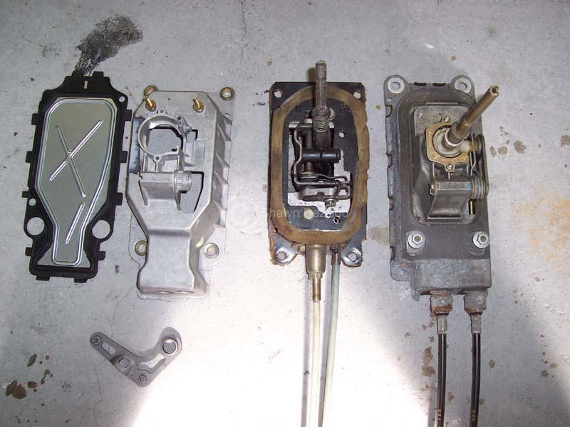
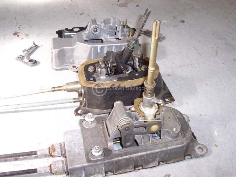
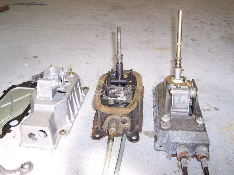
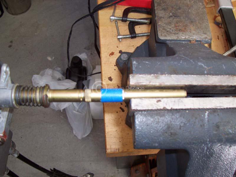
The shaft size it a tad big for the 12x1.5mm Tap, but it can be done. The Threads just don't come out perfect, but it's only holding on a shift knob anyway
January 26, 2010
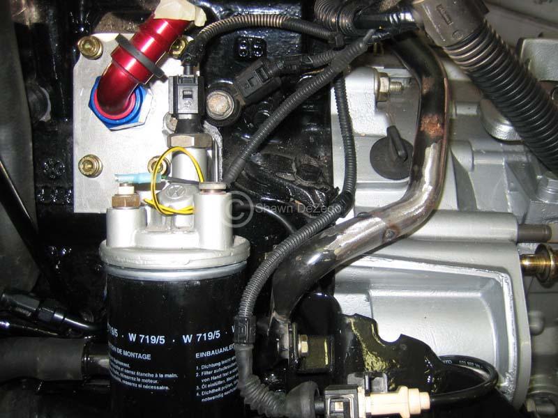
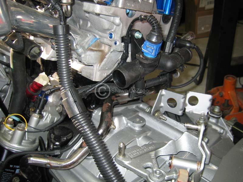
Here is what I have been working on. Coolant Pipes, Timing Cover and misc BS that you never think about doing hybrid stuff until you run into it.
Since the ABA is a tall deck block, there are no Timing covers that work, so I grafted to upper AEBs to account for the 15mm difference. You can see the start above, but I merged them for good today. I also had to remove the bump out to clear the belt going to the rear mount alt.
I also threw a few rivets and backer in there for good luck..
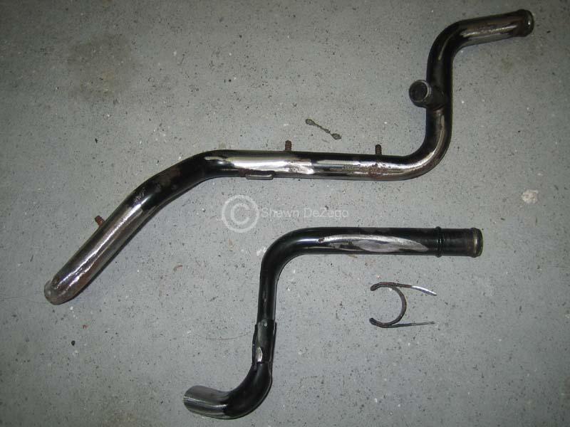
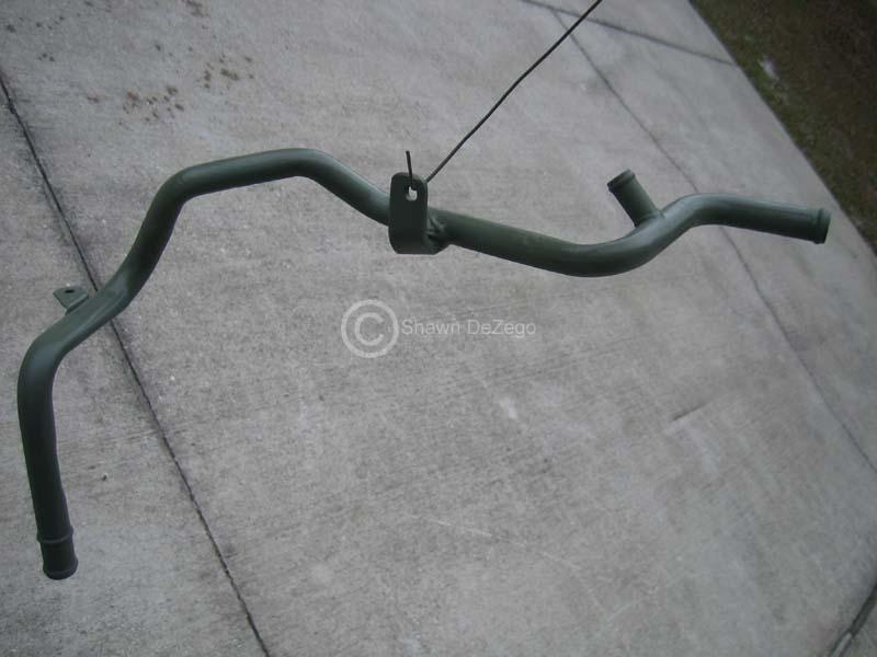
Coolant pipes....
I took the G60 lower and the ABA upper, cut and grafted them to clear the 02m nicely, Also added a brkt to support.
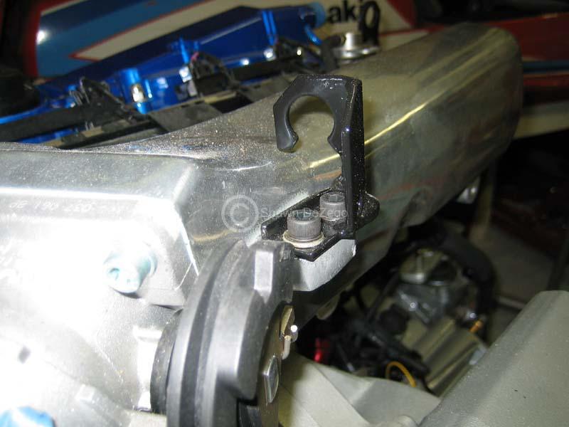
..and the throttle brkt that I needed to make fore the Euro AGU intake for good measure.
Next off is making up my Flywheel lock to torque the ARP crank bolt to button up the rest of the front of the motor and make a Special T for the Coolant bypass circuit off of the head flange. I bought the AL pipe to do this, but just need to take it up to the lathe.
January 28, 2010
Bypass Coolant pipe. Was able to make it up to the shop and spent some time on the lathe yesterday and welded it up today. I still need to add a support brkt or two.
February 22, 2010
Got quite a bit of stuff done over the last couple of weeks, but I have had a project (not pertaining to this build) that I can not show here
Here are a couple of pic from some more time consuming bs... Oh, If anyone wants to rent my paint booth, LMK
February 23, 2010
Up toward the beginning of the thread, I pictured the Supersprint Mk2/3 16V Header that I bought new for a small fortune. The plan was to reflange it and tweak the pipes (offset between 16v and 20v is only about 1/2 inch).
However, at the time, I completely forgot that the 16v Head's Exhaust face is 90* with the block deck (like the 8v). Whereas, the 20v is on an inward angle of 20* (so 70* with the block deck). So, to use the 16v header and reflange, I would also need to come off the flange first with 20* turns to connect to the header...
I do have another 16v 2L motor, so I may just keep the SS header for that and make my own, but as always time is money.
Another option is that Raceland now makes an exact replica of the SS header for an absurd price of $140, I may consider getting that and then hacking as described above and I won't feel too bad. Their headers are actually an amazing quality for the price and I don't know how they freaking do it... I Guess like everything else, 5 letters C H I N A
1.) Both the Supersprint as well as the Raceland are identical designs since RL copied the SS They are both Twin Y Headers.
2.) I am running the Stock Euro Large port (AGU) intake matched to my ported head. Eventually I will build my own, but that is down the road when I can dyno before and after effects.
3.) Cams are stock initially, but this will go along with #2 above. Gotta get it on the road first, broken in and Base line Dyno'ed
Kyle,
WolfGti originally used the stock Euro N/A AGN 20v Ex mani and Mk3 downpipe. This is really a piss poor manifold, but good in that it is bolt on. He later had Joe build a custom 4into 1 header which came out really really nice.
April 19, 2010
I have made some progress on some odds and ends, but have been real busy with other projects. I just finished remodeling my son's room. 4 day projects turns into 2 solid weeks morning and night ...one thing after another.
Big progress will be happening here real soon.
April 20, 2010
I still have a lot of stuff to do before I will be ready to rip down my running car. My goal is that when I do get ready to swap, it will only be a VERY short down time (week or two).
Things left:
- Rebuild and port spare Charger
- Shorten Axles
- Powder Coat Subframe, carrier and lower Rad support
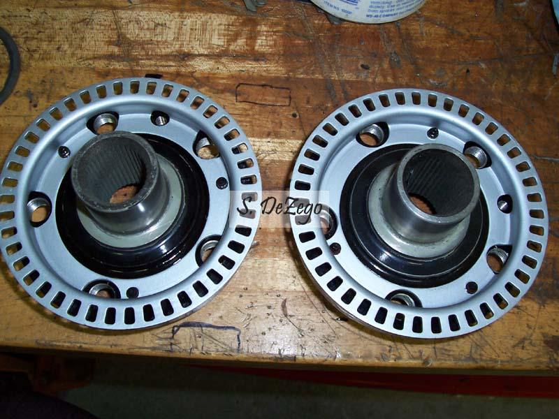
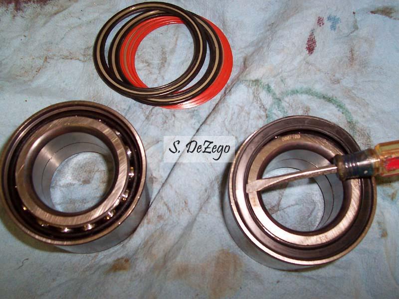
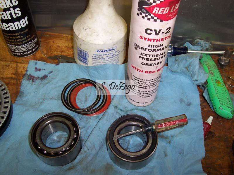
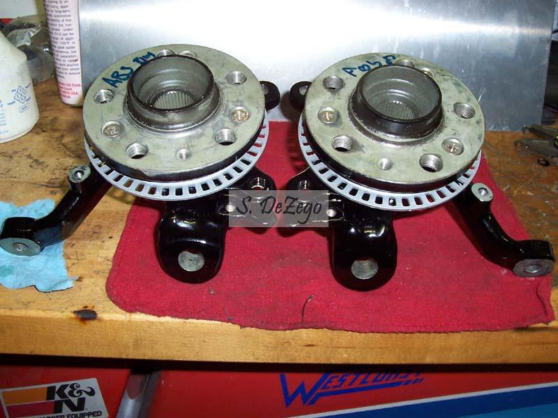
- assemble knuckles (re-pack new wheel bearings)
- press in A arm bushings and assemble KFrame
- Finish custom Wiring harnesses and disconnects to Megasquirt
- Make port matched intake mani Gasket and button up
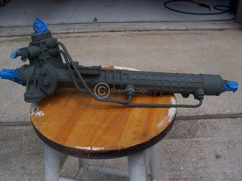
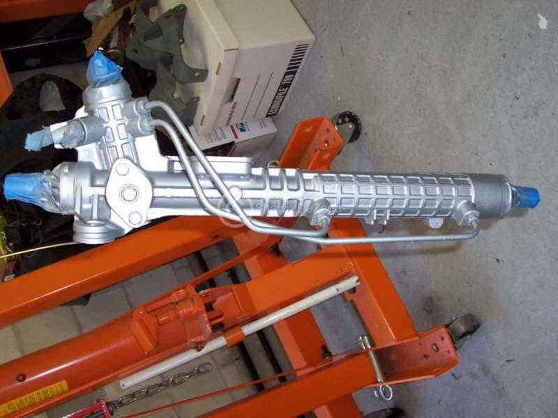
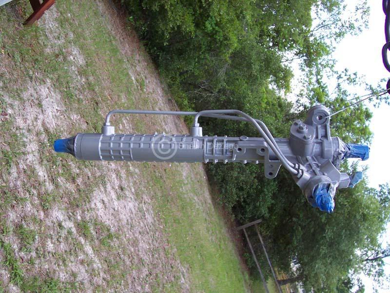
- Clean up and paint Rack
- Fab Block Breather setup and Catch can, etc
- Build Header (probably won't do this ahead of time as I want perfect fitment)
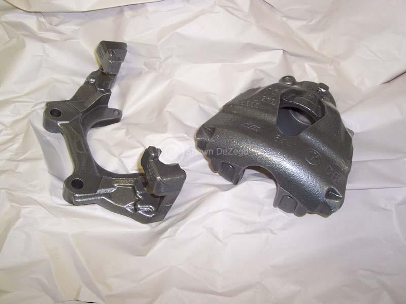
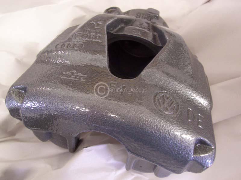
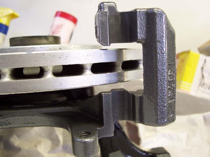
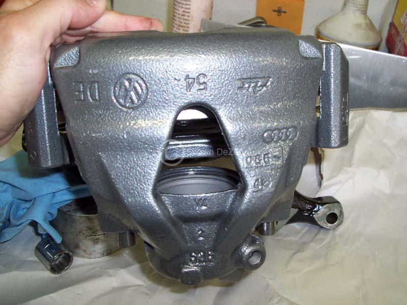
- Rebuild front calipers from 337
- Machine parts for 02m Master Cyl onto Corrado Pedal Assy
- Build SC bypass Circuit (still undecided if this will be mechanical like the G60 or if I will attempt to use something like the APR R1)
- Build IC mounts and Prep and Paint RS Front (although I go back and forth on the RS). I have the precision Core and RS, so I will likely go this route at least initially and then may go A/W and stock front down the road
- Build IC piping
- Work out hybrid A/C lines and possibly Evap Core to clear Rear mount Alternator
- Fab up a lot of stuff (alternator Heat shield and misc stuff)
- Wrap up coolant pipes, lines, etc
- Decide if I will re-spray the bay while the lump is out
- ... I am sure there is a ton I am forgetting ...
Things still left to Buy:
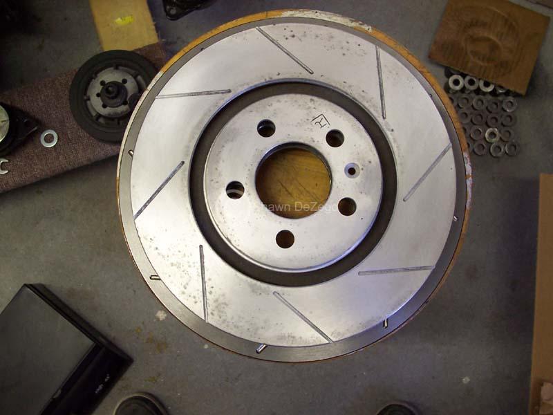
- Front 312mm Rotors/pads
- Front Brake lines for 337 calipers
- 5 Lug wheels for Front (no budget to go crazy so I may just get 2 of the same R1's in 5 lug for now)
- 4 EGT probes
- IC piping
- Brake line for ABS delete
- ... a ton of stuff I am forgetting
Everyone has their sob stories about their lack of time, but mine has been a mile long for the past couple of years and has been plagued by hundreds of other projects taking precedence along with Family obligations. Just know that I am no slacker Also, there is nothing about my swap that is straight forward and there is an immense amount of time in planning, engineering and fabricating details. It doesn't bother me though because I can go out to the garage and rip around in my Corrado and not have to look at it on blocks or something like that.
Also, as you can imagine, this has been a very costly ordeal. I have most of the stuff gathered, but still need to spend quite a bit out of pocket and with the economy being in the toilet, I am hesitant in doing so.
S
April 29, 2010
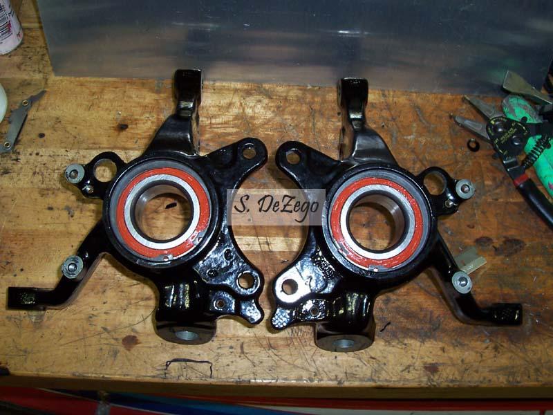
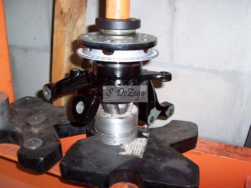
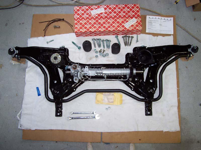
So, after having everyone else projects wrapped up, I made some surprising progress.
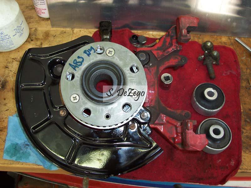
I was able to assemble the Hubs, Repack the new bearings, press in the bushings in the A Arms and get the spindles together. I also picked up the KFrame, carrier and lower Rad support from the Powder Coater. However, I asked for Gloss and he wrote down and did Satin (chassis black) as most people do
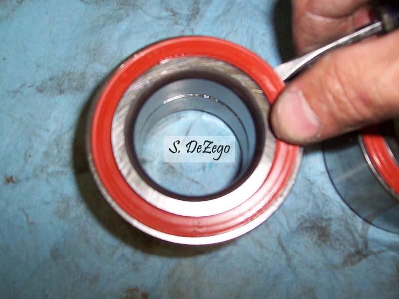
removing the seals and repacking the bearings. The new bearings have very little grease! I have a special crapsman screwdriver than I ground down to aid and prevents nicking the seals. It still takes a steady and patient hand.
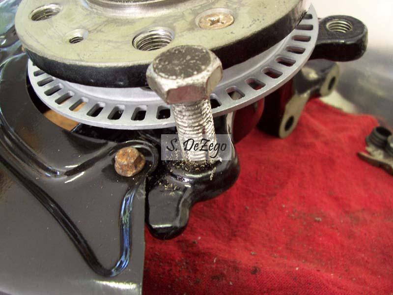
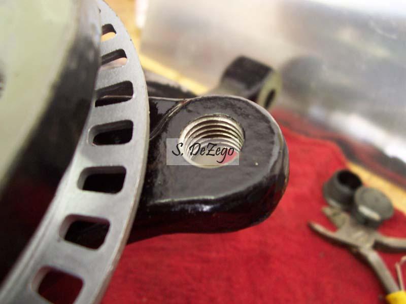
I apparently didn't have the proper thread pitch tap, so I made my own to clean up the threads .
April 30, 2010
I also test fitted the 337/20th 312mm Carriers and calipers on the Vr spindles. I bought the 337 Dust Shields, but they do not fit proper and I will likely just run the Vr ones.
As Mentioned above, I also got some stuff back from the Powder Coater
Notice anything different here in the next 2 images?
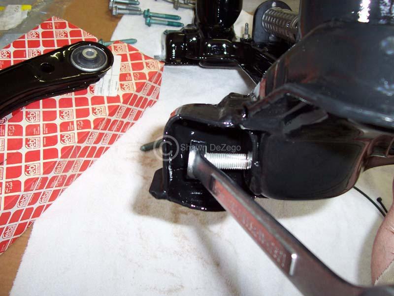
A Arm bushings are the suck. No more Poly on this round. R32 Rear and stock Front.
April 30, 2010
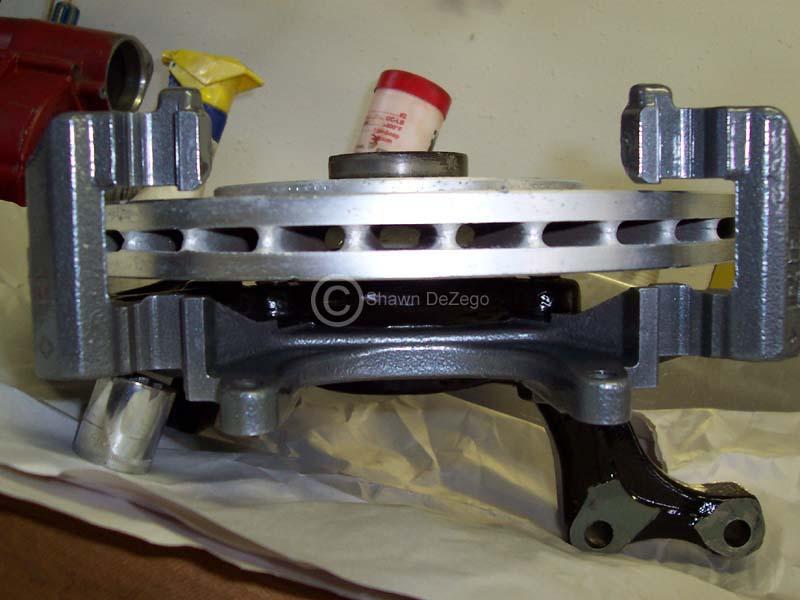
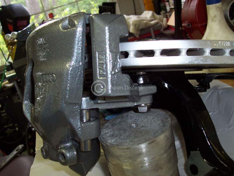
Got the Calipers and carriers back from the PC (no likey red). Test fitting using Vr Rotors just to see the offset. People say I need 5mm shims behind the carriers, but I don't see it. The offset should be the same on the vr/337/20th rotors, so this shoudl be the spacing with the proper rotors. I will know for sure when the proper ones come in next week.
May 07, 2010
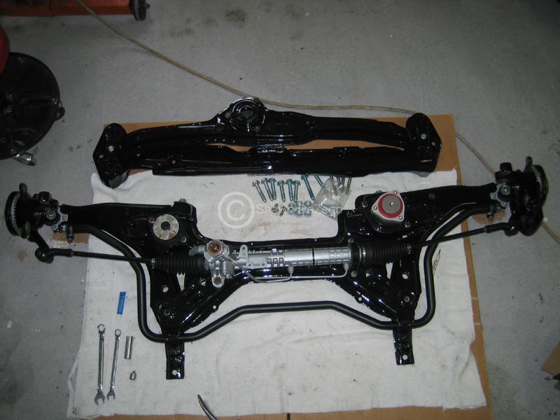
I just got done cleaning and painting the rack. I also scuffed and shot the Subframe, Carrier and Lower Rad support in urethane clear.
I just wasn't happy with the satin finish the powdercoater did and I am pretty sure I told him gloss
I also got some new parts in. pics soon.
May 10, 2010
Here are a few updates: As mentioned, I was not happy with the satin finish powdercoat, so I scuffed and shot with a Urethane clear.
My Home Made Thread Chaser that I used for the Carrier mounts worked great for the SF too Kind of hard to see the channels though.
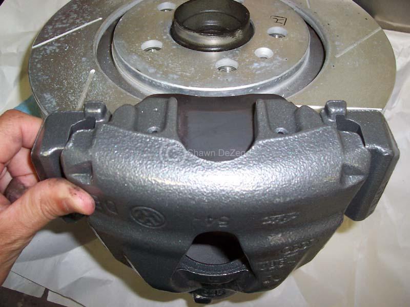
Also, got my 12.3" rotors in. Yes, they sure are heavy.
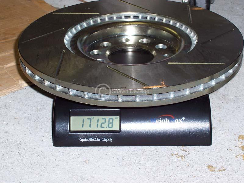
But big compared to the Corrado's
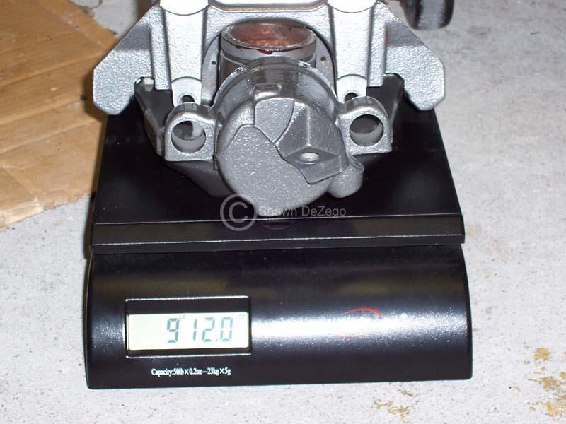
Calipers are a tad heavy too
June 04, 2010
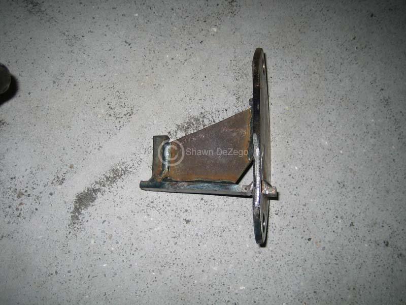
Made a Flywheel lock for the 02m to finally tq the ARP Crank bolt.
I also made up a Cover for the crank side (since there is no vBelt pulley), as well as making the lower bell housing shield.
...and bolted on the front mount for final as well as the other custom coolant pipes.
July 16, 2010
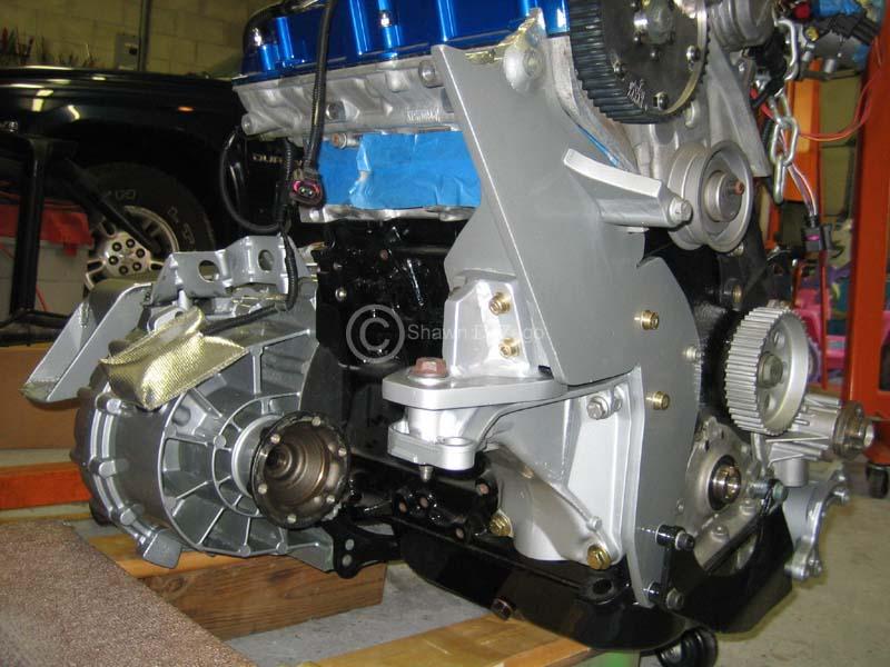
Some progress pics. There are a lot of smaller details that have been address but unaccounted for in pics, etc.
After all of the port work on the head and manifold that I did as well as the time spent port matching, I wasn't happy with the way the stock gasket or the Spacer fit, so I ended up making my own.
Fit is absolutely perfect so my OCD can close the case on this.
Not happy with this fit...
Custom gasket
All new hardware, subframe finished
Finally in the "Mock Bay" Yay!!
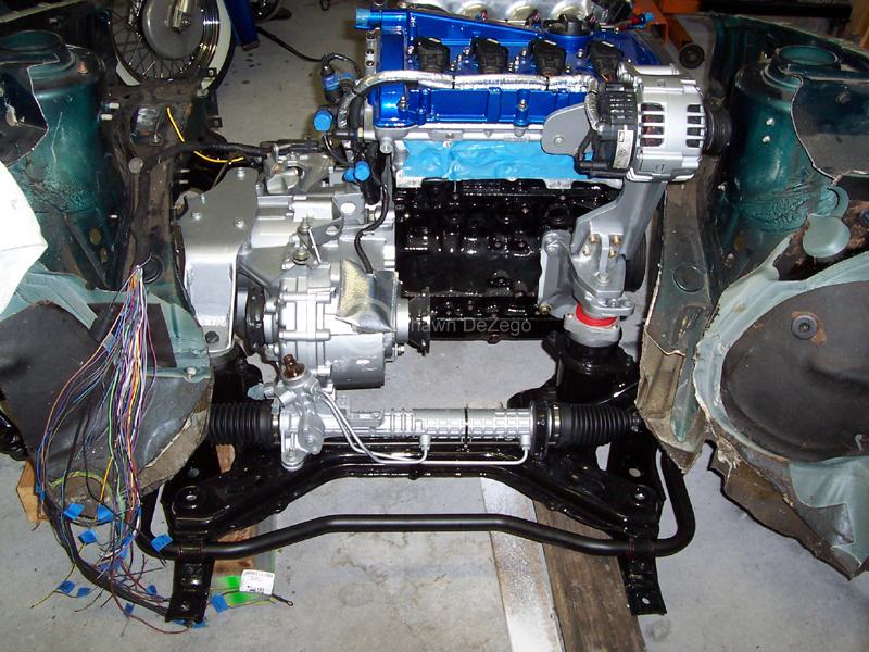
July 19, 2010
fter getting the engine into the mock bay, the first problem has arisen and the first design revision is already in order...
The serp tension arm shown below hits the frame rail slightly. I measured and thought there would be enough clearance, but there is not. I could probably trim the lip off of the top of the frame rail there and dent in the side of the rail a hair, but I feel that is a hack. Also, even if I do that, there will be enough clearance, but not enough to swing the tensioner all the way up if I ever need to remove it in the future to change timing belt, etc.
So, I am resigning the arm from scratch out of 3/16' steel as opposed to the stock AL arm with is about 1/2" thick. This will give me plenty of clearance and capability of removing when the engine is in the car. So, I already have it well under way, but need to take some pieces up to the lathe so I can press fit some bronze bushings, etc.
Everything is else is looking pretty good though.
July 23, 2010
Spent some time on the Bridgeport and lathe the other night and finished up the machine work on the new arm. Made two bronze bushings for it and honed them to size. Just want to add a grease fitting to it and paint.
It worked out great, but I still need to address the minor clearance issue with the Shock and the frame rail. Should be much easier than making a whole new arm assy. Have a few options in mind.
I'll get some pics up soon.
It also goes w/o mentioning, but I would much rather run into this now in the mock bay, then down the road when I go to put the motor in.
S
August 04, 2010
UPDATE:
Got some other progress done. Lots of little misc things that aren't that exciting for pics. I also rebuilt the Master for the non-ABS swap and assembled. I also started looking at what needs to be done to use the 02m Master for the clutch. I will post pics when I do the mods to that, because they are a plenty. Some just adapt the 02m line to the 02a master which should be fine (there is a bubble flare section in the 02m line, but most connections and push together with C-clips).
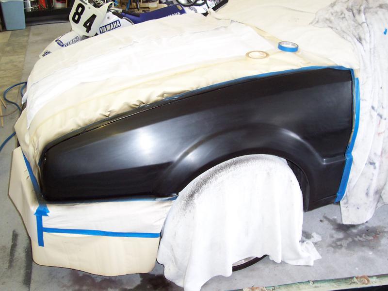
Non-Motor related. I also decided to fix a small dent that was in my on the side if my hatch since I bought the car. What started out as a touch up, snowballed into fully fixing the dent and spotting in a base/clear, in addition to respraying the d/s Fender to fix a few flaws and a couple of spots in the D/S door
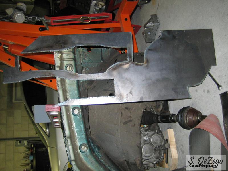
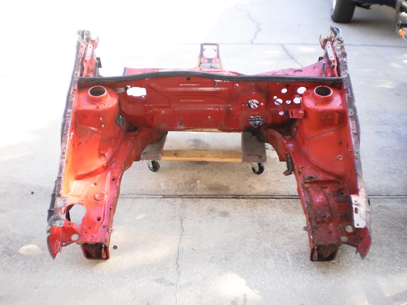
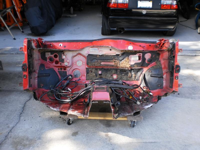
Also, I picked up a full front clip so that I can mock up the A/C lines and Header before the old lump comes out of my car. The clearance issues with the belt tensioner pushed me to want to do a full bay mock up so there would be no issues. So, I drove a couple of hours today to do some surgery on an unwieldy patient.
This time, I kept the whole front clip, rain tray and all the way back past the shift box mounts in the tunnel.
August 20, 2010
I am really on the fence right now, as I was not going to worry about it until I got closer to the intake piping. 2 options are a DV or weld the mech G60 bypass onto the intake pipe just before the TB and run a simple linkage. I already cut one off and headed down that road, but if I could get away with a DV, that would make things much simpler. I am just not sure about Drive ability as I have no experience with trying to use a DV with the G60. If I were to go that route, my preference would be a diaphragm type (as opposed to piston) and nothing smaller than an APR R1. And that might even be too small I do have a stock 1.8t, so I guess I could try it on my current G60 just so get a feel for the response, etc. It is what BBM used on their 2screw.
Shawn
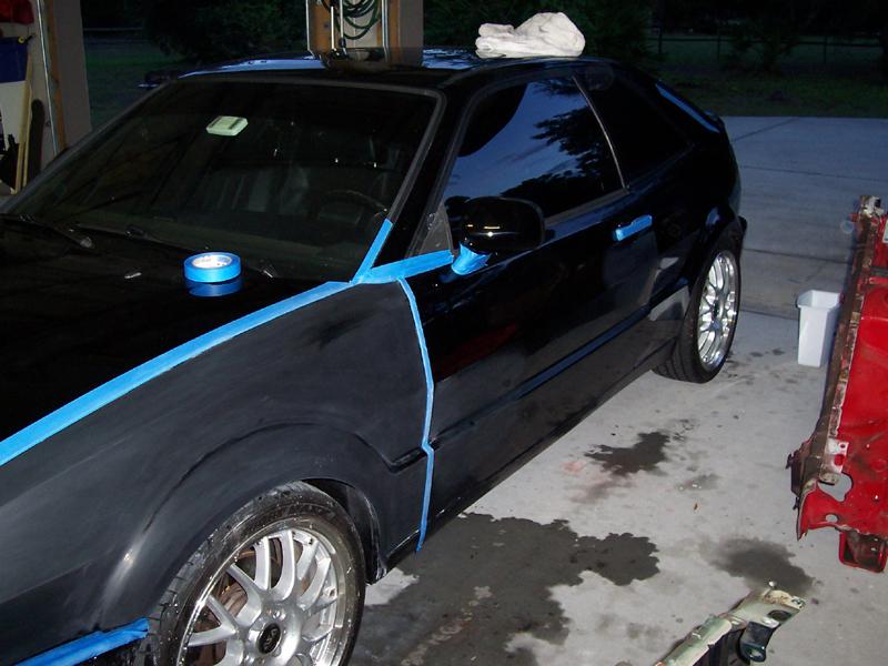
Here are the pics. Again, this was intended as a stop gap and snowballed. I actually have a set of Vr fenders that may end up on the car in the end. This is what happens when the wife and kids go away for the weekend...
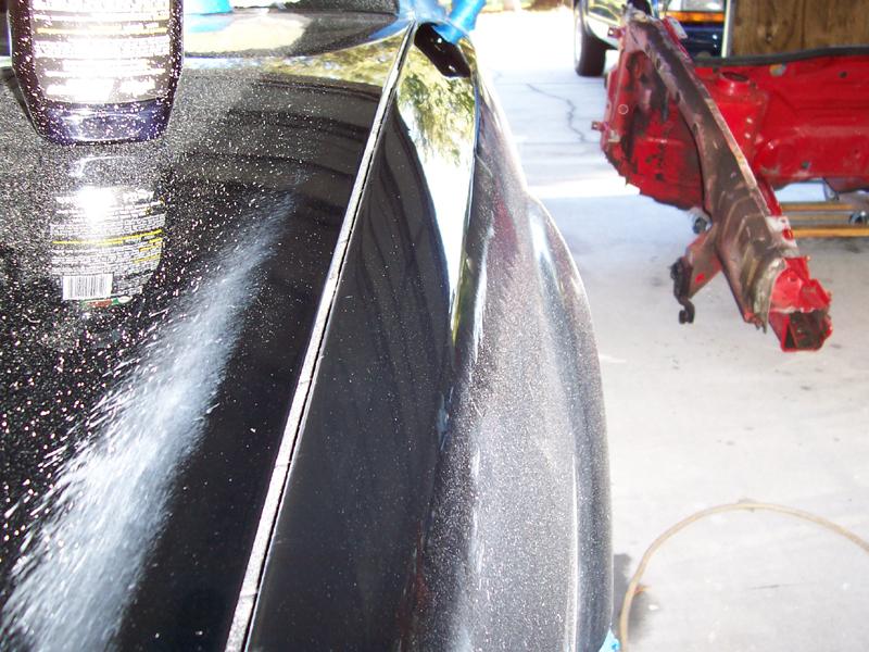
Base Coat and Color sanded
Clear Coat wet sanded
Initial Polish
More Polishing
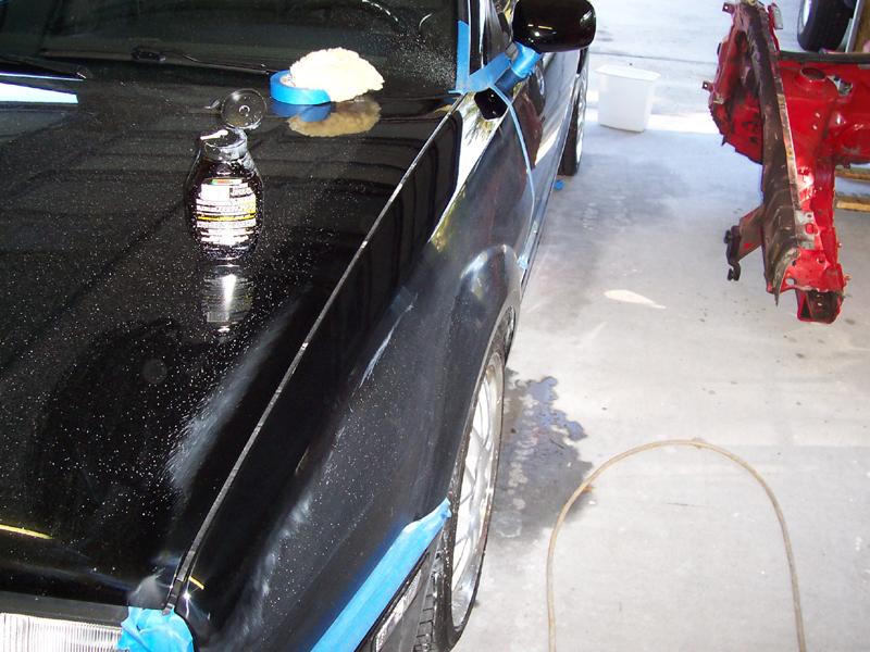
More...
Done
November 18, 2010
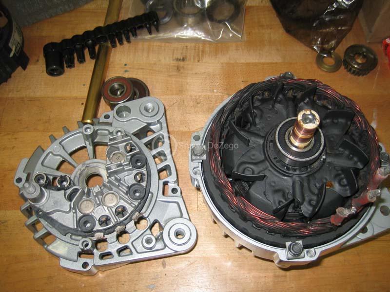
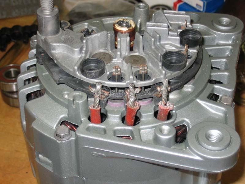
Been working on some small items lately like rebuilding my spare charger.
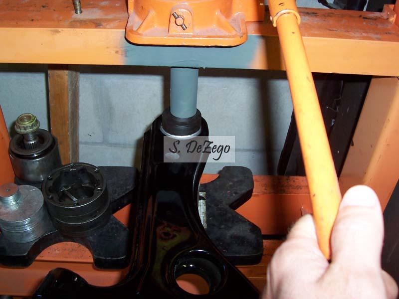
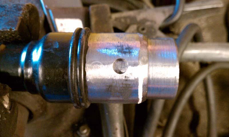
Also, I had a request to shorten someone's axles, so I thought it a good time to do mine at the same time.
I usually cut -> V-Groove the axles halves ->machine a sleeve to press inside and splice the axles -> true if necessary -> weld
I have them cut and I picked up some metal stock today. I am taking the day off tomorrow, so will head to the shop to machine the sleeves down on the lathe for a press fit. Will then take them back home to weld up. Hopefully, I will get them completed tomorrow along with some other odds and ends.
...taking some measurements
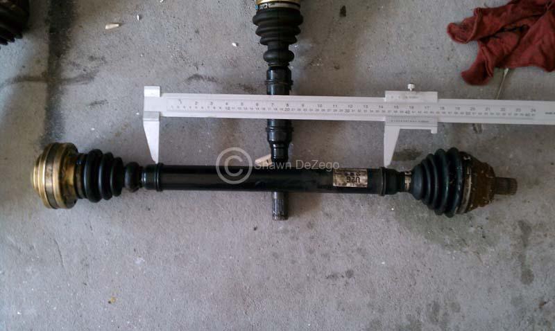
...Stripped down
November 19, 2010
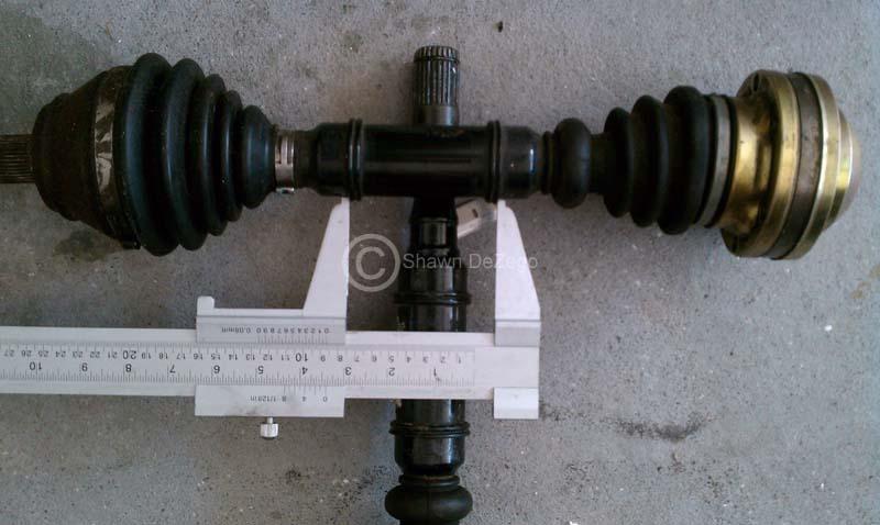
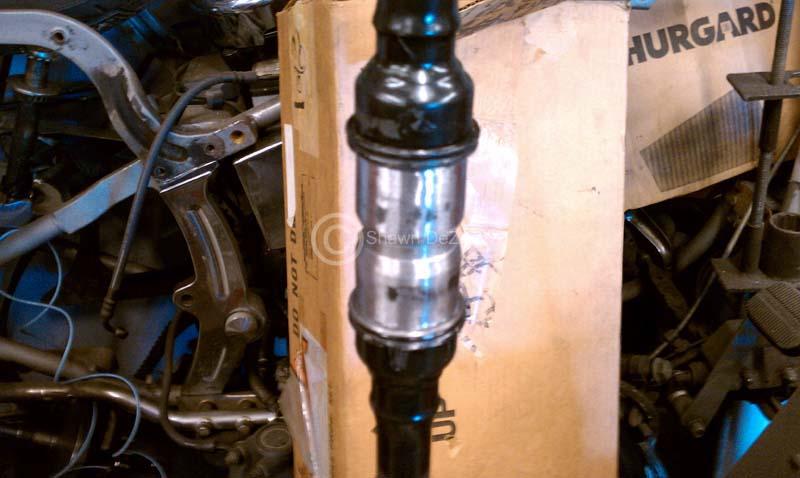
Axles are all done!! Shortened and trued
Pics should be forthcoming...
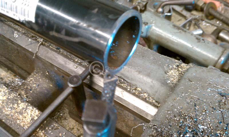
Refacing the cut from the chop saw and beveling
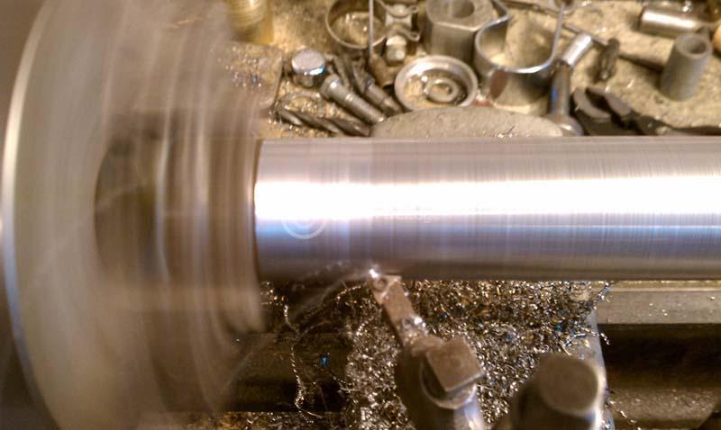
Cutting the sleeve for .0015" pres fit
Pressing sleeve in Axle half
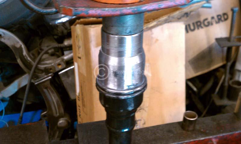
Blind holes to weld sleeve to Axle
Welded Blind hole
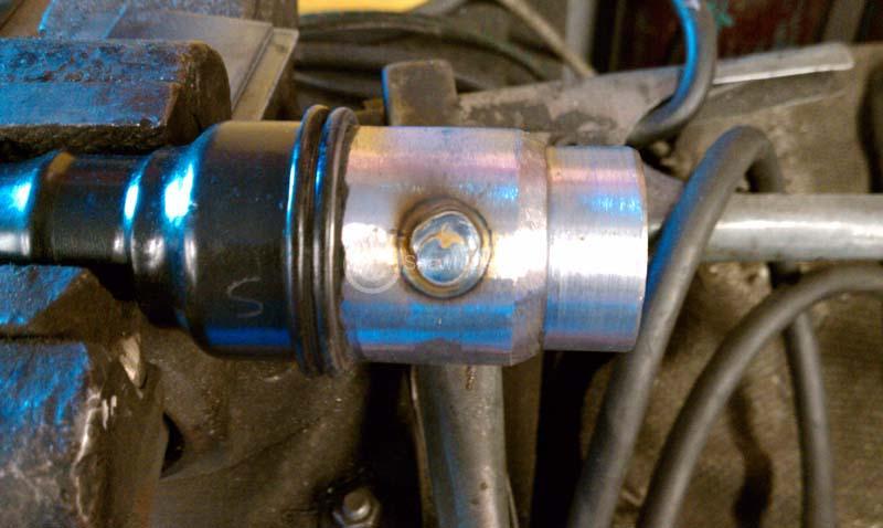
going together
For some reason, I stopped taking pics. Will take some of the finished product this weekend.
S
November 22, 2010
December 18, 2010
I started assembling more of the Mock bay to get an idea of IC placement, A/C lines, bumper, etc. I may use the Mk4 A/C condenser as it fits with a few tweaks (with the help of a couple of side brkts to the Rad). This makes sense for a few reason, but one being they are on $80 new any anything to get away from Corrado specific stuff is all money after that... But, it also relocates the drier, press switch, etc and I can use some of the Mk4 lines. The one from the comp to the condenser directly. I have a disturbingly large collection of A/C lines and parts from different VWs
I was also really giving thought to a different front mount from what I had planned. I may have mentioned, but I have the Dietrich RS front and a nice new Precision Core that was set to go in it. I really want to keep the stock bumper though now (especially with Dogger's 70mm front lip that is coming), so I may get creative. In close comparison, I realized how much more space there is with the Vr upper Rad support using the G60 Rad even before cutting the front vertical strut. There is also more vertical space because the Vr support bumps way up on the Pass side where the rad ends where the G60 slopes down. I never realized this before. So, I really see no reason why one could not stack the "right" IC core like the Mk4/5, etc does. I am going to start to investigate some factory cores to check size and outlets. Since this is in front of the Rad, there is surprising space there as mentioned. I'll take some pics and measurements of what I am talking about.
December 27, 2010
I started getting the power steering lines in. Some slight tweaking on the rear was necessary to clear the custom rear mount which was known. I also fabbed up a small support bracket to mount the lines to the rear S/F cup flange (same location as stock), but not shown.
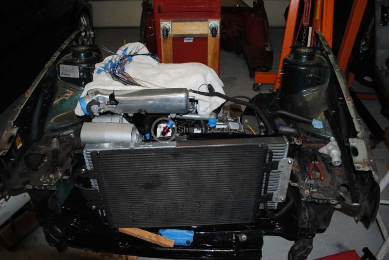
Looks like I decided to go with the MkIV A/C condenser for the reasons mentioned above. I still have one small brkt to make (line support), but it's easy. Here are some of the mockup pics.
MkIV Compressor and discharge line
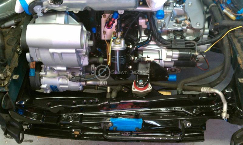
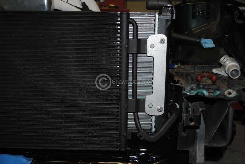
MkIV condenser mounted to the G60 Rad. Notice how the left side has the Drier mount, which fits around the rad nicely and clear the G60 and compressor w/o issue. The high side line comes off the bottom of the drier and I will show when I get one on.
Bracket I needed to Fab. Also needed to redrill the left side tabs (no biggie) and need to make the line bracket still.
December 31, 2010
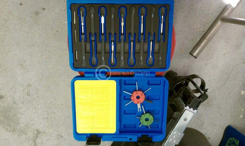
I forgot to show one of my Christmas presents to myself... For those who don;t know, I like to read the Bentley wiring diagrams before I go to bed
I had the "star" tools below, but added the full kit and are they nice...
January 11, 2011
Thanks man. Some progress pics coming soon. Been jumping around a bit, but making progress. I also ordered a bunch of stuff that I was waiting on.
New Harnesses for cabin side of MS3 + MS3x as well as the MS3 processor upgrade and lots of other little stuff.
I will be upgrading MS on my PG/G60 in the next couple of days from MS1 to MS3. I could stay MS1 (even on the new setup), but MS3 is unbelievable and the MS3 (Expansion board) makes most of the items that I was planning in building custom circuits for plug and play.
Fully sequential Fuel and Spark using the 20v COPs, + TONs of other useful inputs and features.
January 18, 2011
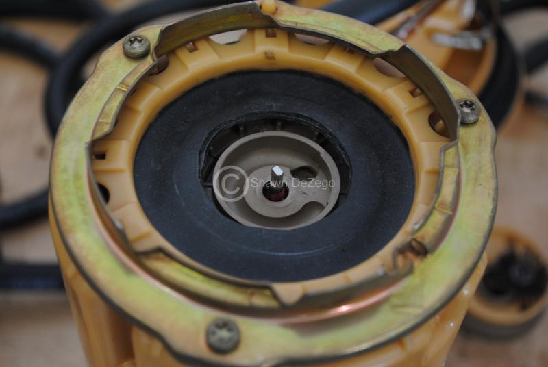
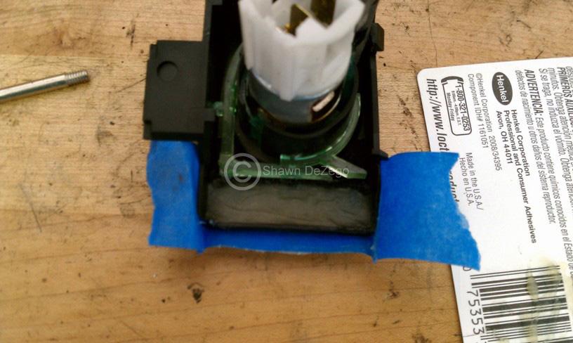
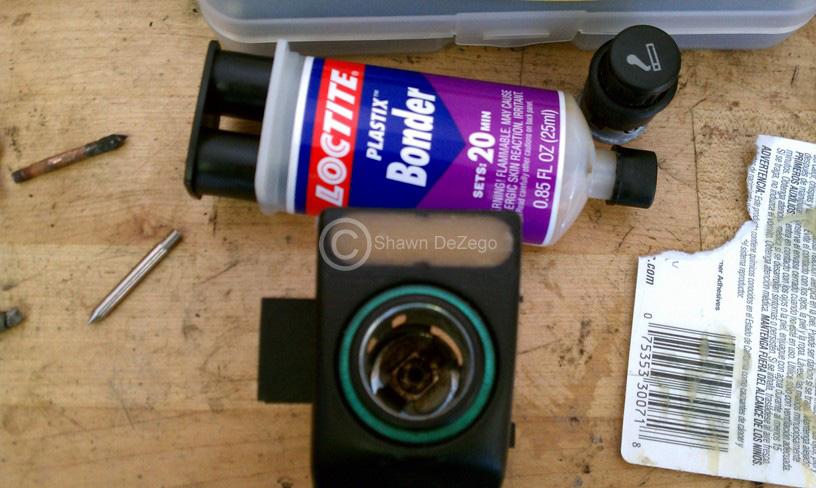
I deiced to change my Fuel Tank to the later intank single fuel pump setup. The 2 pump setup is really a piss poor design. If I ever decide to go back to a 2 pump setup with a large external pump (i.e. a CIS or 044) I can and will have an easy way to mount the transfer pump in the tank using the bayonet ring/housing. The Mk2 style tank mount setup with it's telescoping mount, and $40 rubber connector is My Sender acting goofy again after fixing it once, was the final straw. Plus the stock external pump and housing is another great design
So, I decided to rebuild one of the few single pump setups that have met their fate with bad gas over the years. Full Thread is here -> http://forums.vwvortex.com/showthrea...Pump-Rebuild-P
The Top and lower diaphragm seals from the inner pump to the housing are the only thing that usually goes bad in these pumps. Granted the $89 TRE replacement makes it hardly worth the effort of even screwing with it...
A couple of pics from my post above.
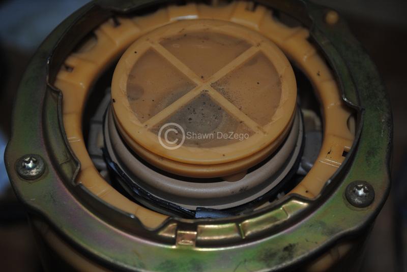
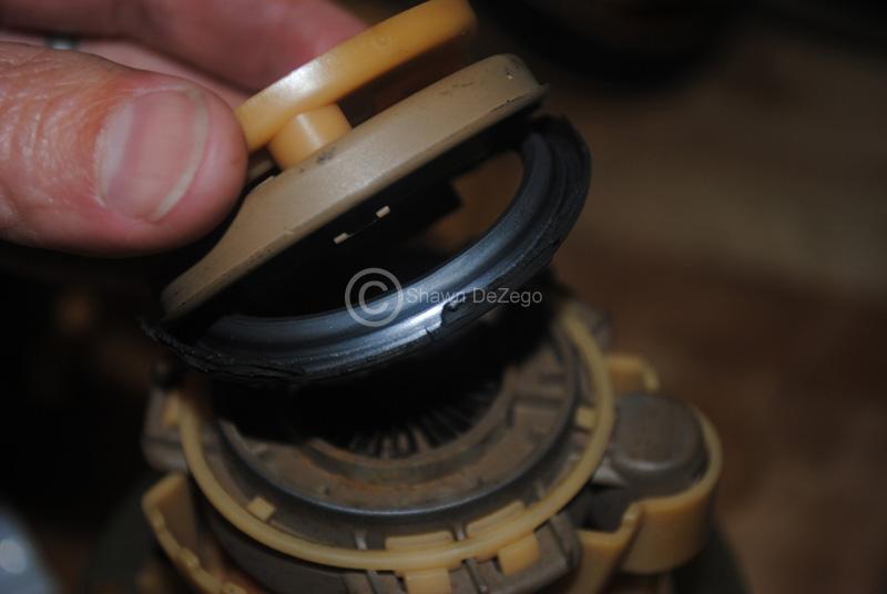
Bottom side with Pinch Ring installed.
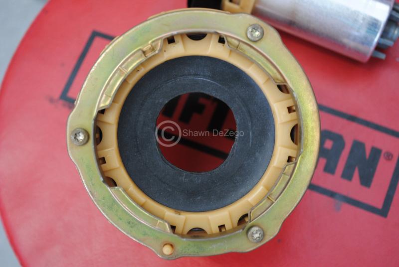
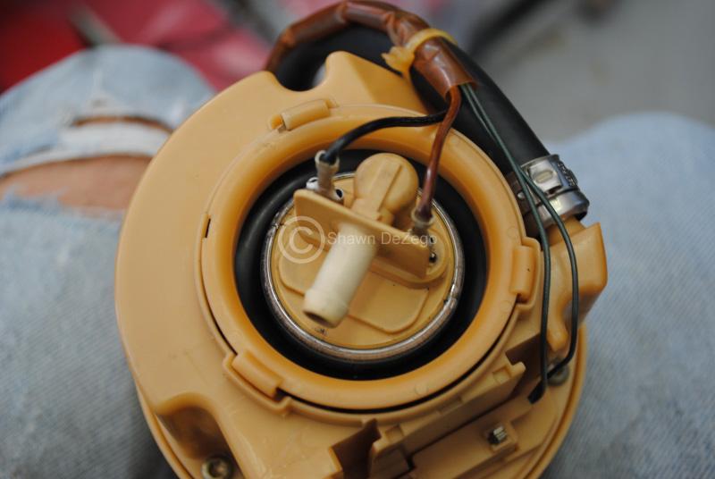
Pump Ready to go into housing. Note: is the isolating seals are shot, then you are in more more research to try and find something suitable to replace them. I have seen these completely melted away before.
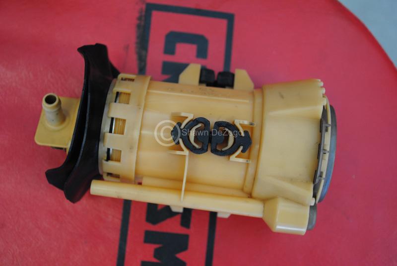
Going in and ready to install lower ping seal Ring and 1st stage intake and screen.
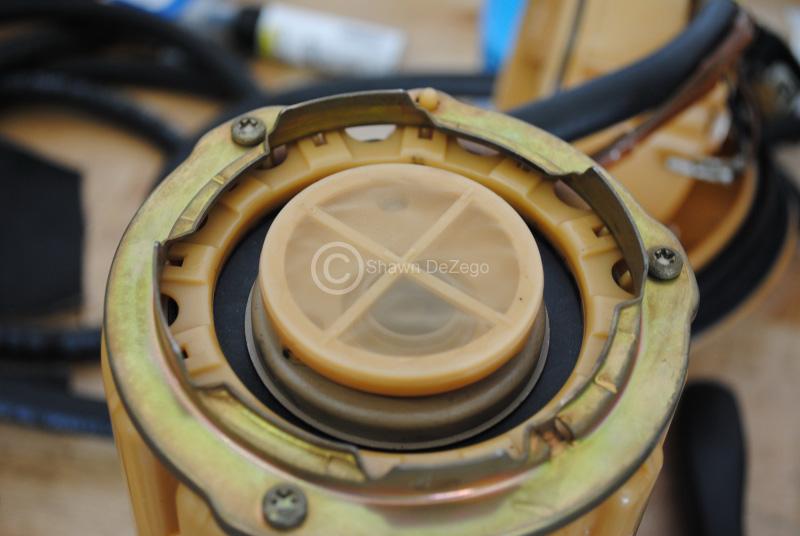
Top Pinch Ring and seal installed. DONE!
January 26, 2011
So, I have been busy learning the ropes of MS3 and the G60/PG is running again. I ended up changing a few inputs/outputs around which will help in the motor swap. I added a VSS in as well so now the logs will show gearing, Speed and you can set up things to calc Tq and Hp, etc (thanks Jeff for the tip!). Already MS3 is better than I imagined.
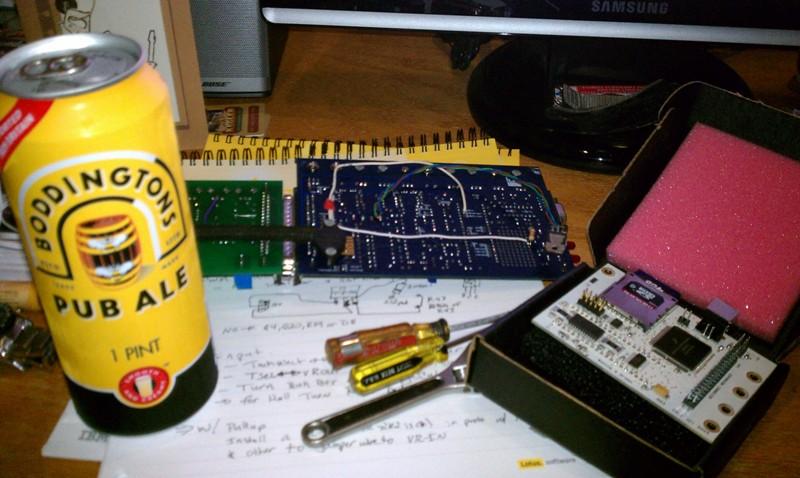
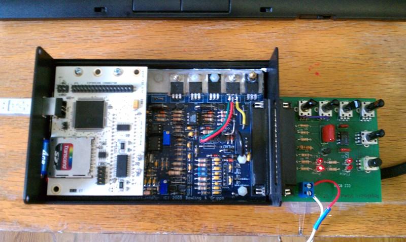
MS1 Processor out
MS3 in and testing on the benchtop Stimulator (no ms3x expansion board in yet, but that will come with the new motor and not necessary now)
I have also been making some small progress on other fronts, but mostly spending money and acquiring parts.
haha, still have to tune it, but no biggie. Used my base maps from MS1, imported and interpolated to 16x16 maps. Should be a good start. Fires right up and idles great
You can export the .vex maps from MS1 and import into MS2/3, but since MS1 maps are not 16x16, you need to do quite a bit or work. ...in a good way. More resolution is always a better thing.
Funny story though, my daughter came out in the garage the other night and was watching me work. Apparently, she is going to be a typical woman becuase her exact word were (and I sh!t you not), "...and dad, when you are going to finally put this new motor in? I'm tired of looking at it..." wtf
January 30, 2011
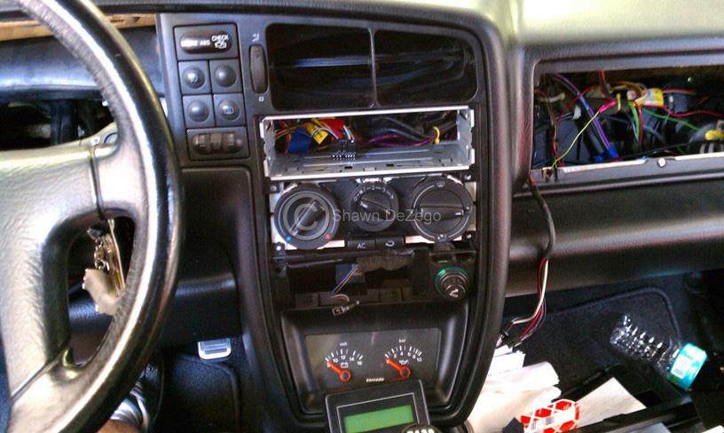
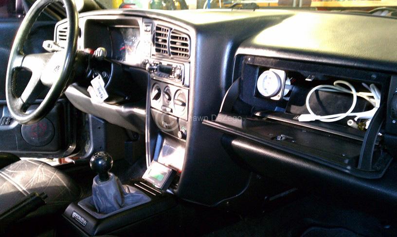
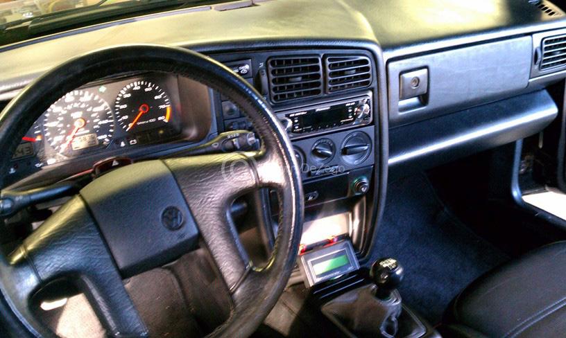
Since I had to rewire a few things for Meqasquirt3 and I had the glove box out, I deiced to swap the HVAC controls yet again. This time to the MkiV. I have been wanting to do this for a long time and had actually modified the controls with LEds about a year ago ..nothing in comparison to what Dirk does.
Full thread from original interior swap and the latest additions in here (note: 2 tone leather went to all factory black a while back) -> http://forums.vwvortex.com/showthrea...Pic-centric%29
Also got MS3 fully tuned this weekend, but only took about 45 minutes.
I also had to change a couple of jumper wires from the pic posted above. I had to chance the VSS signal in to go direct to a spare input pin on MS. I had it going through a conditioning circuit and was not getting the speed signal.
All is well not tough and I now have speed in the logs as well as gear indication
MS3 is really amazing. I though it was going to be hard to beat MS1 with the HiighRes Extra code...
January 31, 2011
Did a little bit more work tonight and finished up the MkiV Condenser install. (don't mind that PS pipe as that will likely be going).
Next up should be IC fitment. I am really on the fence about this...
February 01, 2011
Using the MkiV harness and ECU is not a bad way to go (especially if a stock tune is fine). I am just strongly against the "chip Tuners" and the price they charge... AEB head is great, but plenty of power to be had from small port head. I would get what is readily available at a good price.
Well, after putting the front end together on the mock setup, taking detailed measurements and trying to fit my Precision Core under the stock bumper, I have come to the definite conclusion (I think), that my only solution for a good IC is:
1.) AWIC
2.) Build a custom FMIC
Guess which one I am going to undertake
My constraints (which did change from the start where I planned on running my Dietrich RS) are now to use the stock bumper, get proper air flow for IC, Condenser, oil cooler and Rad, and look as close to stock as possible. That means to even run the Lower bumper grill as well. I in no way want to hack up a stock bumper and try to stuff a core in there that is wedged to the rebar and blocks all proper air flow.
I did some research on some cores with my measurements and I have a few options. I just need to decide, bite the bullet and build. Bell cores are hella expensive, so I may need to try and set up a reseller account through my brothers shop. Or find a comparable efficient core.
Stay Tuned..
Shawn
February 02, 2011
The closest part of the Rad support. I have some better pics I will post up. The Vr support is narrower (allowing more room) between the Condenser and the support itself, but either one would need to be modified. I will mod and reinforce.
Yea, a factory front mount would be ideal and most are pretty inexpensive brand new, but the problems with the ones that I have searched (2.0t, Saabs, Volvos, etc) is that they are either too tall, or the outlets are positioned to face rear and come in either over the top or sides of the rad and point back. This might work with a narrow radiator (i.e. like the Rallye golf FMIC), but as you know, with FL heat in the summer, a black car and A/C to boot, you need as big of a rad as you can get. So, I am not downsizing that.
What I foresee, is a FM similar in size to the ones you mentioned (large surface area), but the Inlet and Outlet will come off in the same plan as the IC but head out toward the right and left tow hooks. Then pipe around and up as usual.
I have the design already finalized in my mind and it will definitely work nicely. I just need to find and buy the right core to get started.
A 2.5" core looks like it would be perfect, but I could squeeze a 3" core in there if need be. Bell doesn't have a 2.5", but they have a 2.25 and a 3". The Difference in flow is very small (only 25cfm).
February 09, 2011
Took a break on the intercooler briefly since it requires spending a lot of money I pretty much have it all mapped out though and it will be slick.
I really hate rebuilding axles and packing CV joints, so glad they are done and on! Redline CV2
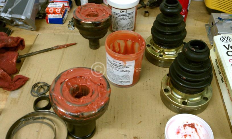
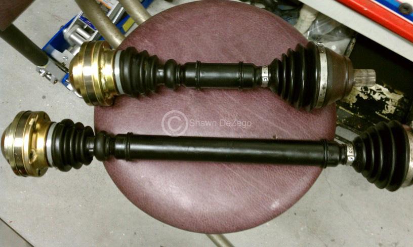
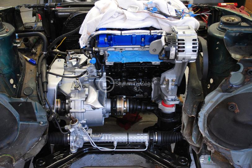
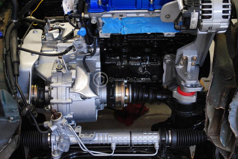
About 1/2" clearance between the CV joint and the trans cup now.
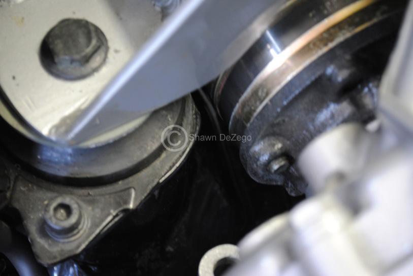
...kind of blurry, but oh well.
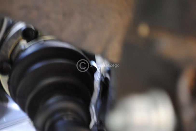
April 05, 2011
Things have been progressing, but haven't posted much progress as things that have been completed are all over the place and nothing significant lately other than wrapping up Megasquirt3 and getting a final tune on my current setup.
I'll give a small update though:
I made the decision to ditch the really nice precision IC Core that I bought a long while ago when the intentions were to run the Dietrich RS front (tells you how long this project has been culminating). I purchased the new IC core (not yet disclosed) and started mocking it up. Some Corrado owners may find this interesting, but I will leave it a that for now. I can only say that it is a very large area core that will look factory and still allow A/C an a full Rebar. Upper Rad support trimming is still TBD.
I have also been porting and rebuilding one of my spare chargers among other things.
I am at the point where I really want this done and in, but my time has been limited to work on this as usual. Money making jobs have to come first and these are outside of by daily job and Family life.
Not to worry, progress pics soon
I have been also working on refinishing my spare bumper so I can get it on to show off your 70mm lip Got a new lower grill, new steel lower support trim , etc.
April 10, 2011
As usual, I have 20 things going on at once, but I did work on the IC setup quite a bit the other night as Lee mentioned. I don't want to post any pics yet though, but will soon.
The reason is that I need to complete refinishing my spare bumper, and shoot my spare upper Rad support so that I can swap them on my car now and take the Vr Rad Support that is currently on my car. ..plus add my SFT 70mm lip on I need this to complete the IC mockup.
Unfortunately, the IC is much tighter than I expected. So MUCH so, that the small diffs in the VR upper Support are required for use and there is also a lot of creativity needed to get this thing to work. Not to mention a lot of cutting here and there (but no mods to the rebar ). I am now confident that it will work, but realistically to try and repeat this solution for others, is not be the best route.
The avenue I almost went down with a Custom Garrett or Bell core and fab up end tanks would have been a better route and could have been made to work with only trimming the down strut on the upper Rad support when using the VR support with the G60 Rad/condenser setup.
April 12, 2011
Crappy weather, so no work on painting the front bumper and rad support to swap so no pics on the IC mockup, but here is one one of the G60 on the Bridgeport opening up both intakes.
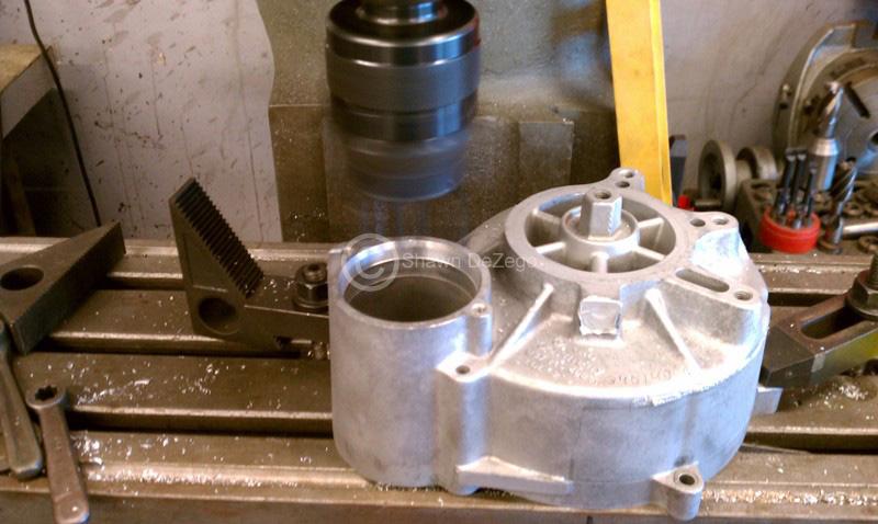
September 09, 2011
Yea
Well after all of the work or replacing the single Fuel Pump swirl pot bladder rubbers, the FP itself decided to take a crap LOL... I decided to go all out and be done (hopefully) once and for all.
Added from this thread -> http://forums.vwvortex.com/showthrea...-small-project
- IE Surge tank
- Bosch 044 Fuel pump
- Stock G60/Mk2 VDO transfer pump (did calcs and flow rate is more than sufficient)
- Custom Made Mount plate, Fuel Filter mount, etc
- '02 Audi S4 Fuel FIlter
- 14mm x 1.5mm to -6 AN Adapter Fitting (Fuel Filter Inlet)
- 12mm x 1.5mm to -6 AN Adapter Fitting (Fuel Filter outlet)
- M5 and M6 nuts for 044's elec terminals (yes, diff sizes)
- Banjo fitting for 044 outlet using the 044 Check valve
- 6' Aeroquip line and lots of various AN fittings
- Earls 5/16" compression fittings to -6AN for adapting to Stock Nylon lines (must get brass insert from hardware store)
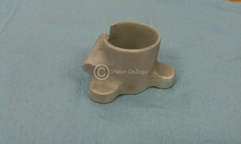
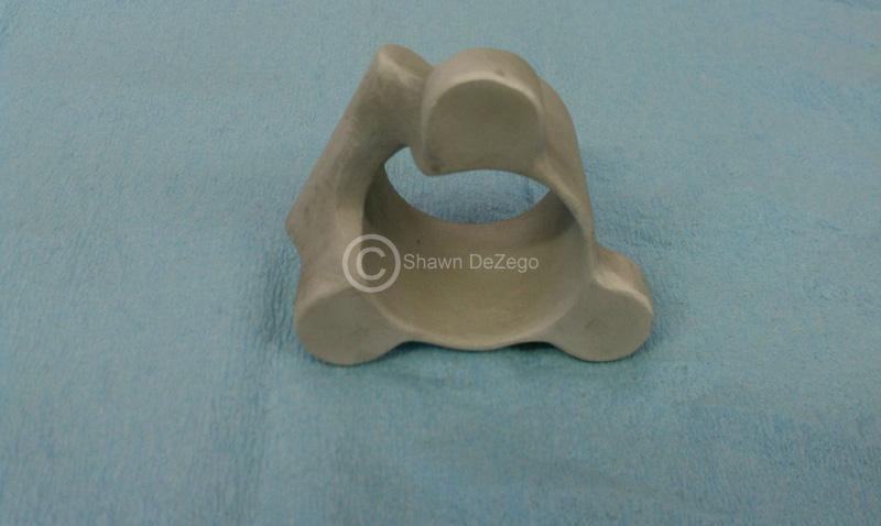
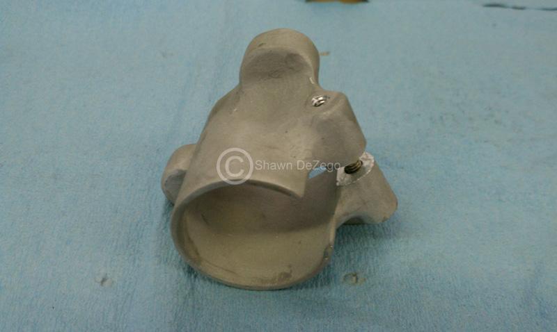
Transfer Pump test fit isolating rubber (Buna-N) was trimmed before install
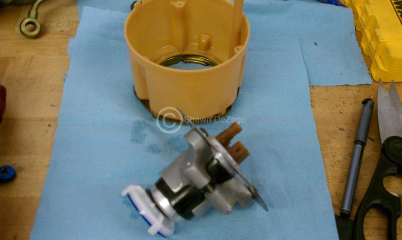
Test Fit before assembling
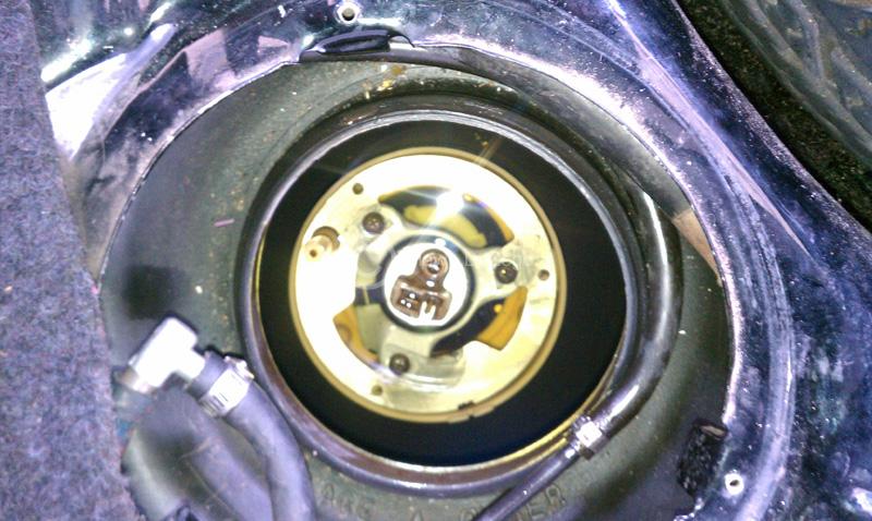
to feed this..
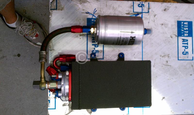
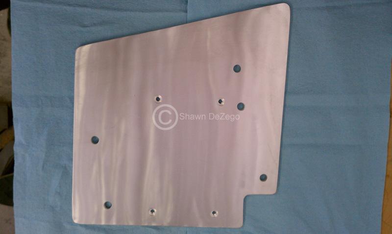
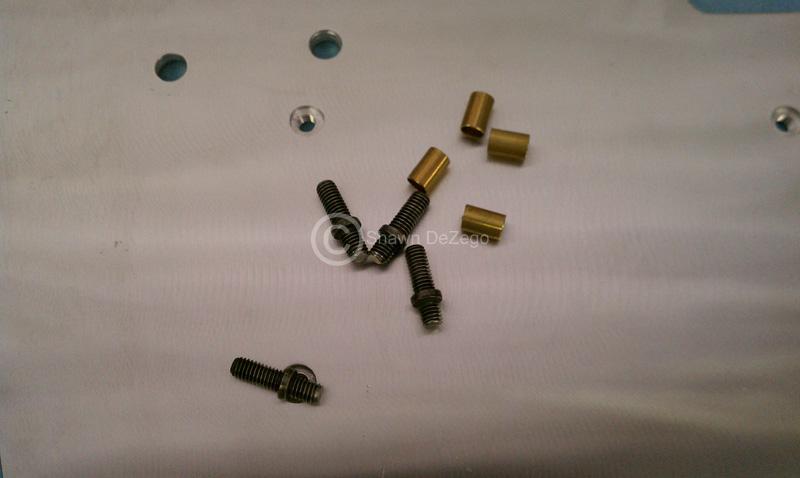
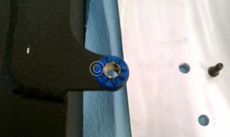
Setting up Fuel filter layout.
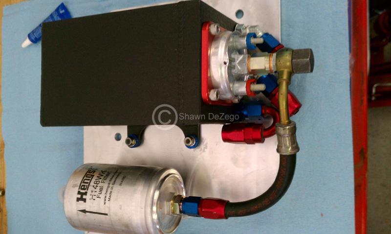
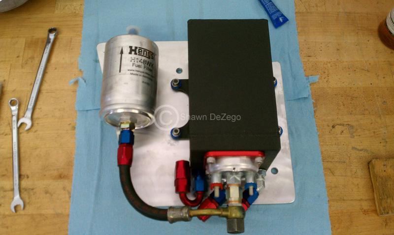
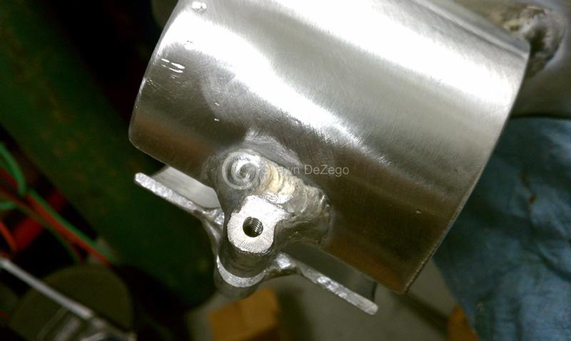
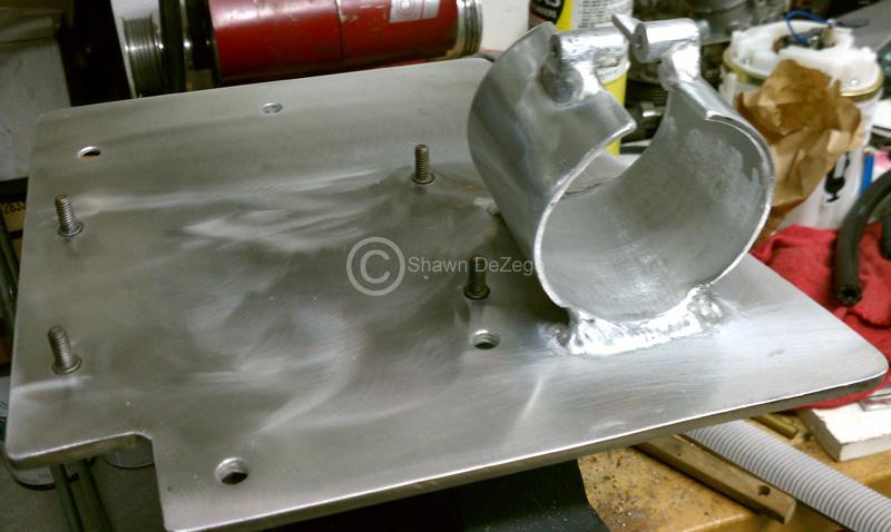
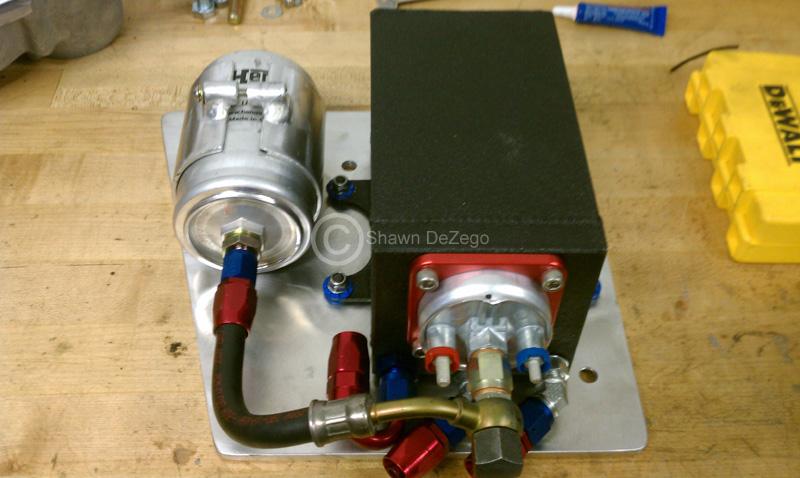
Heat Shield action
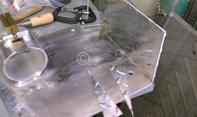
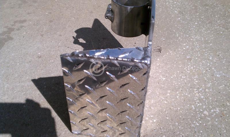
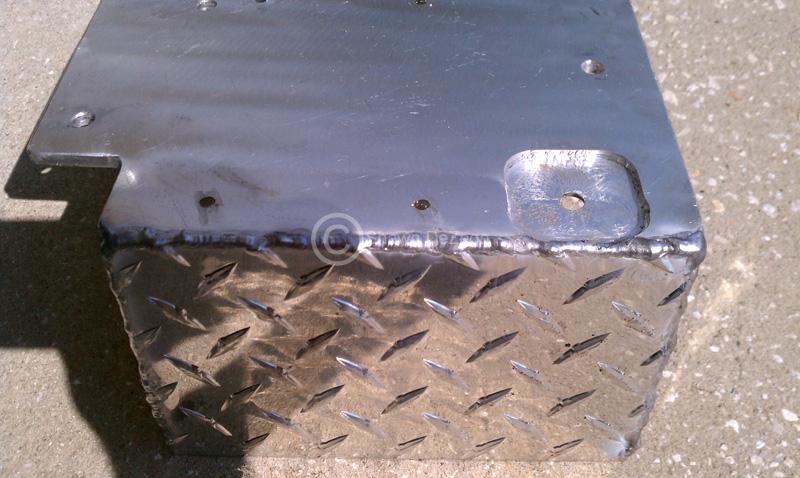
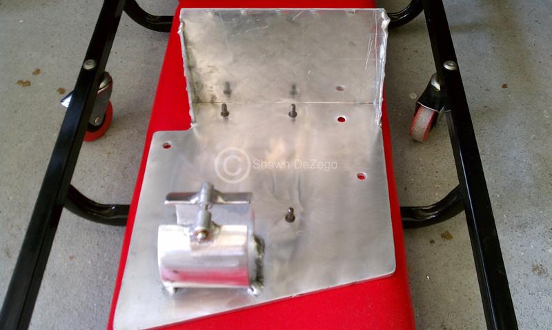
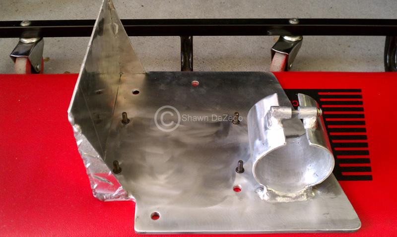
The welds are not as bad as they appear in most the crappy cell phone pics, however, I noticed just as I was finishing that the car seats that someone stacked on my Tig must have slid and cracked the flow meter which was leaking pretty good... I hadn't Tig'ed on it in months and didn't notice/fix it until I was almost done, so they are certainly not my best either.
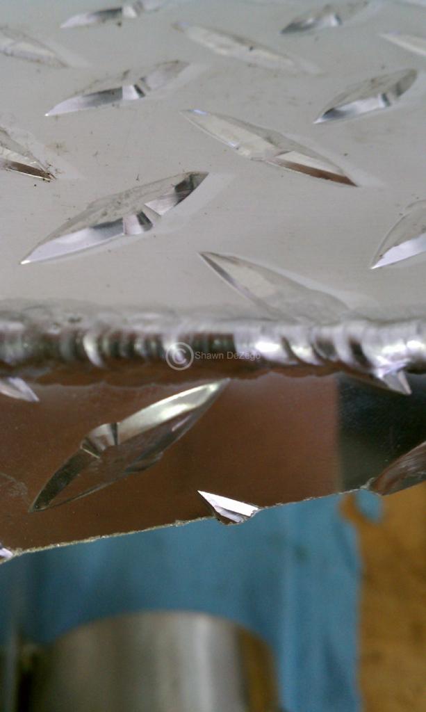
So, for the Factory nylon line to -An, I am using the Earl's Compression fitting, with a separate insert to prevent the line from collapsing. I have used these before, so I know they work well.
Note: the factory line has a brass insert to prevent the hose clamp from crushing.
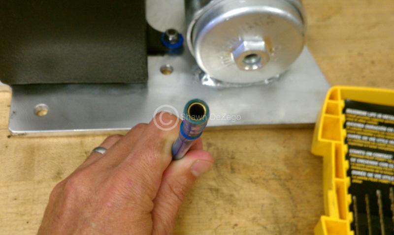
However, in this pic the is a 3/16" drill bit that barely fits in.
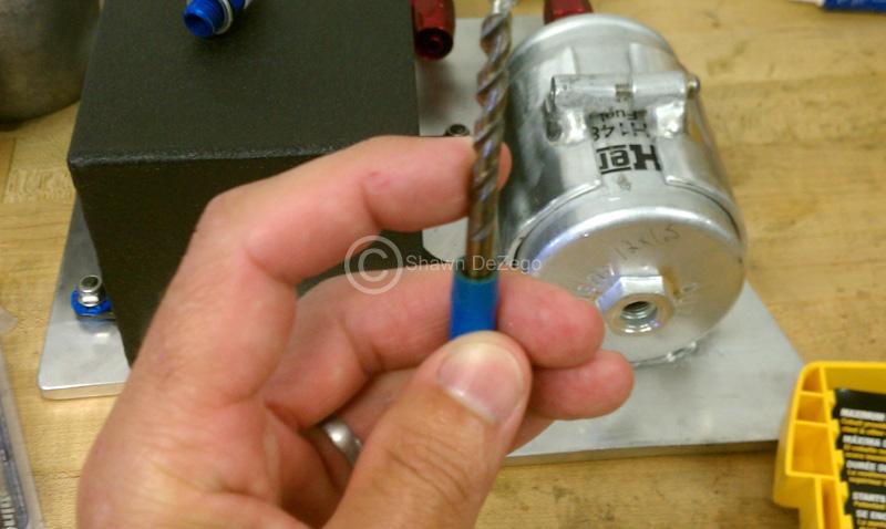
Using a custom insert (from a hardware store, but the flange end must be trimmed) with the Earl's, the inner Diameter is increased to 7/32"+. Not that I Personally really need the extra flow, but I am sure someone who needs the extra flow for E85, etc could spare the expense of running all new lines.
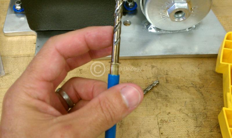
A pic of the whole thing.
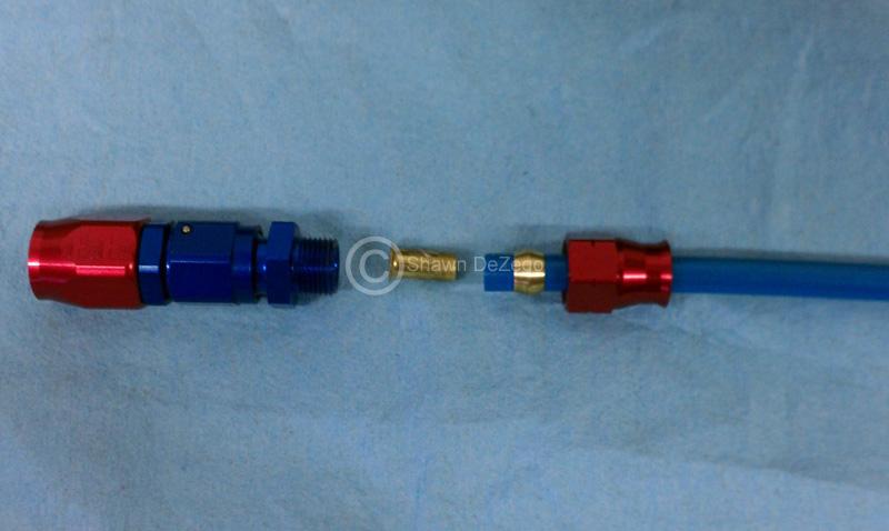
The amount of $ that ended up in this is just retarded, but I guess if I never have to revisit it again, it is all worth it...
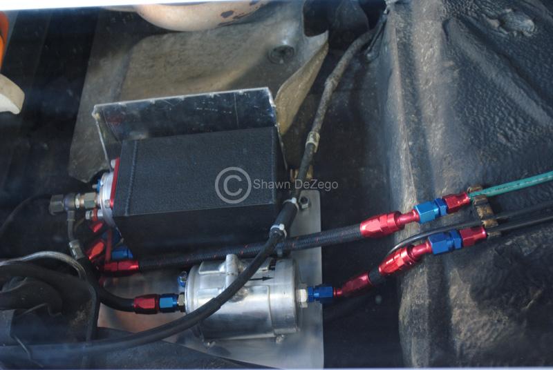
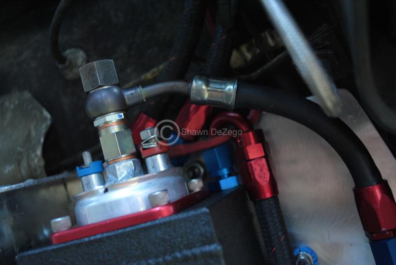
December 01, 2011
I am starting to get back into some work here. Intercooler piping is coming tomorrow, so I hope to be starting on that aspect and make this IC that I have work.
I would really like to have this wrapped up this winter...
January 21, 2012
I finally had time to finish up some paint work that I started, well about a year ago It has been one thing after another and this morning, was the day that I had time and the weather was absolutely perfect! 68* at about 8 am with zero wind, no bugs and low Humidity (A rarity for Florida). When your driveway sometimes serves as a booth, elements have to be perfect
So, I painted my new Bumper (70mm Lip finally will go on!!!) and my spare G60 Rad support. The Rad support is important so I can take the VR one off of my car and wrap up my intercooler project (requires the VR) I started, well over a year ago...
I made a mistake when stripping the bumper and going down too far. There were a few coats over the Factory and used SEM Bumper stripper, but I should have used a softer scraper and tried to take all but the factory finish off. When you expose the bare plastic, there is a lot of prep and stuff that needs to happen to make the primer stick properly.
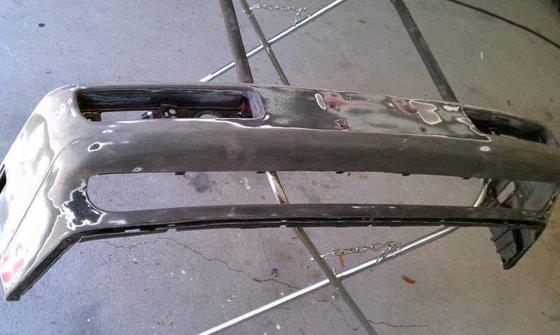
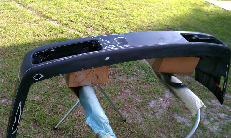
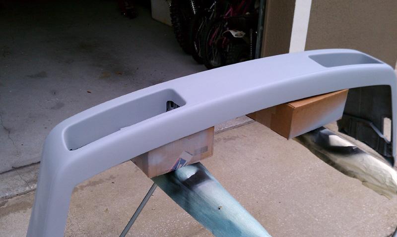
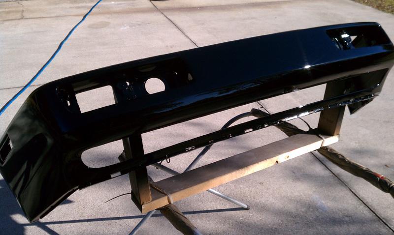
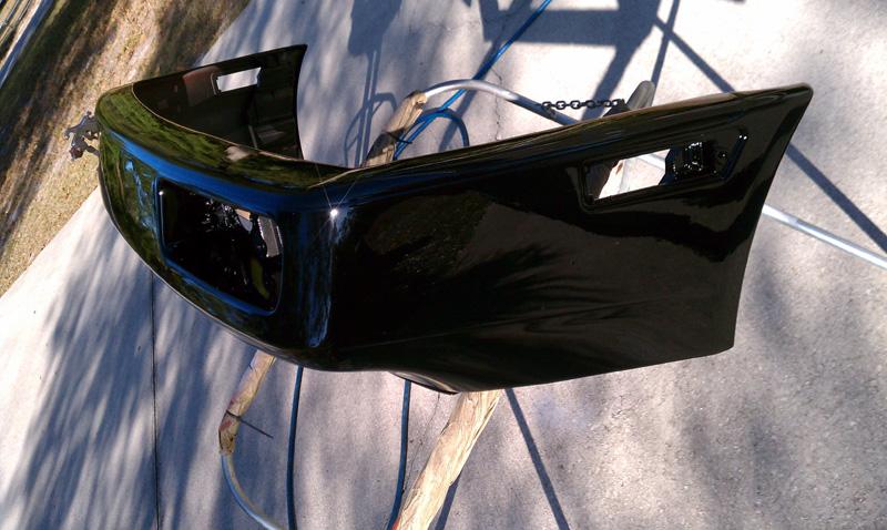

February 02, 2012
ok, I have some updates.
1st, I finished up the Front Bumper, Rad Support and SFT 70mm Lip sans any Wetsanding. It does not need it but I may touch it down the road. There is barely any hint of any peel at all if any, which I am very pleased with 9.8/10. I will get some proper pictures of the car when I clean it all up.
SFT 70mm Lip
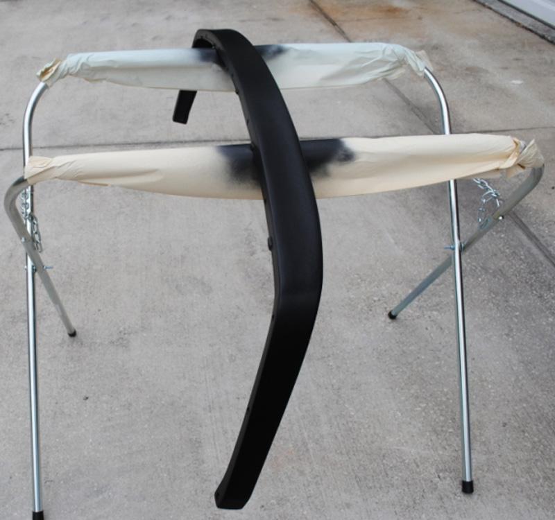
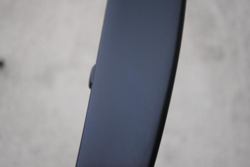
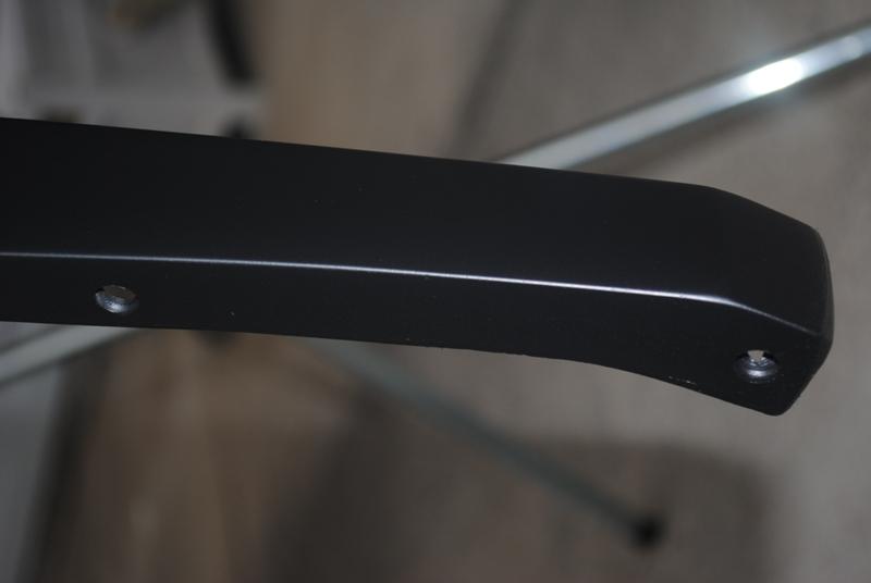
Modified the G60 Support for the VR Grill. This support is only temp anyway which you will see when I post of up the IC work next. ...crappy cell phone pic
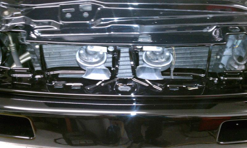
Corrado Reinforcement Lip and Lower Rad Support = 0. Me = 1. It was a hard fight, but I got every bolt in Yes, that is a new reinforcement strip, bolts and Lower Bumper Grill again, proper pics when I get it all cleaned up.
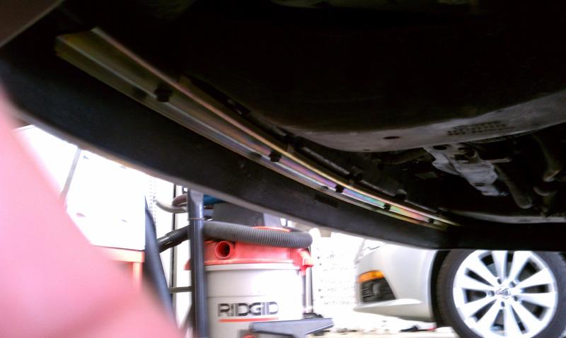
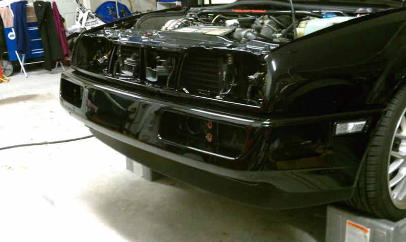
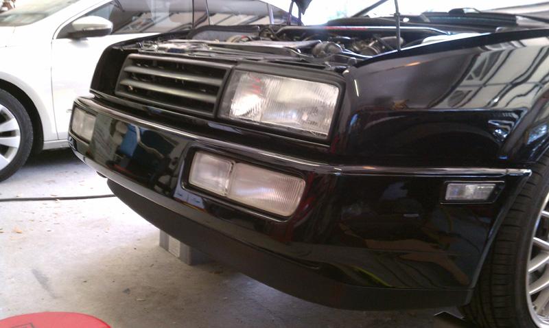
One thing I noticed when I was taking the headlights out that I don't recall when I switched to the VR Ecode Glass and Bezels a couple of years back was that the Bezels were sagging on the bot. There was a gap between the bottom of the bezel and the lens which made the lines not straight. I guess wind was getting between and worsening the fit over the years.
What can I say, when everything is now perfect up front, the little things stand out Anyway, what I did, was just carefully squeeze 3 dabs of clear RTV between the bottom of the lens and the Bezel, clamped and let it set up over night.
Let me state first, that if you are considering using the IC as I am below, know that I bought it with only rough dims and the intention that it was only going to need slight modifications to work (yea right)...
So, in case you were asleep or just forgot from a few pages ago, I am going with a custom FMIC and using the stock bumper, stock Lower bumper Grill and unmodified Rebar. I looked at making once from scratch using a BELL or Garret Core, and in hind sight, it would have been easier in the long run (as would have AWIC)..
So here is the Plan:
- Using Stock G60 Rad becuase it is bigger
- MkIV Condenser (for reasons mentioned on prev pages)
- VR Rad support modified (very important as you will see)
- re-fabricated lower Rad support (Drivers Side where it flares outward)
- a highly Modified big ass FMIC
- unmodified bumper Rebar
NOTE, the info to follow is only for the above Configuration! VR Guys, don't try to get any ideas as you will not have the clearance if you have A/C.
Here are the Basic Constraints for this config as shown below in my highly technical drawing.
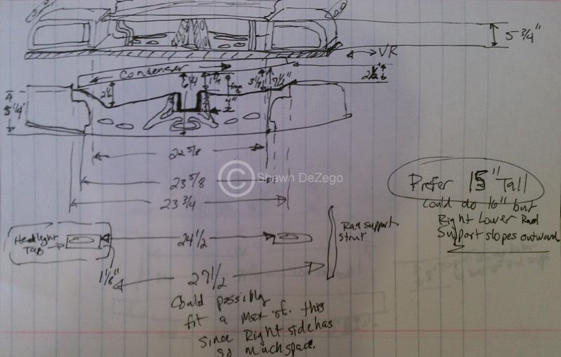
Notice there is a bit more room than one would expect between the Condenser and the Rad support when using the VR support on a G60. This is the reason I needed to paint my spare G60 one to swap on my car so I can finish the mockup on my build.
Shown Actual VR Support on G60 w/ A/C. (note: see why I needed to repaint my Ft Bumper and Rad support? )
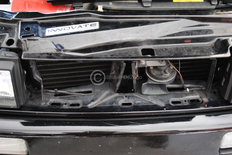
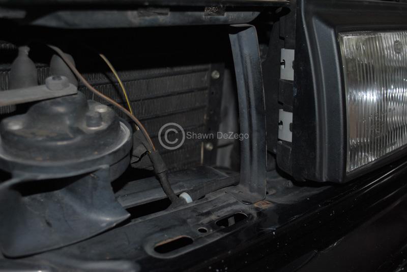
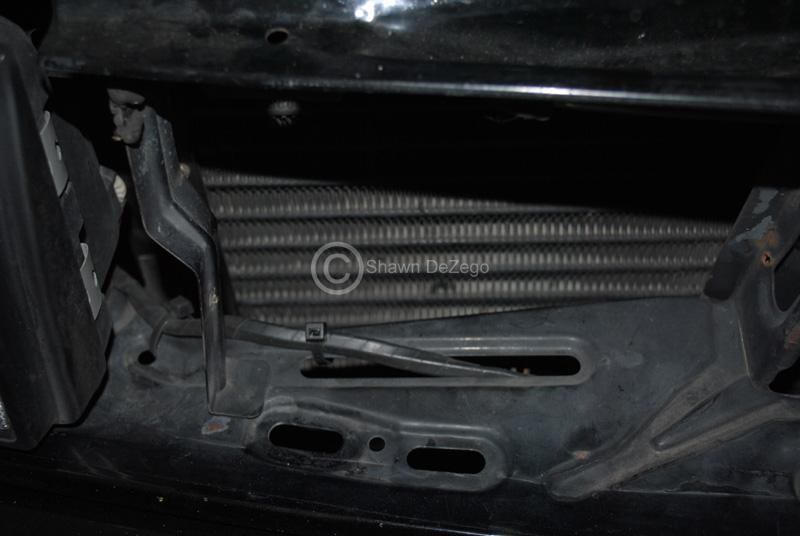
...as compared to the same setup with the G60 upper Rad support.
Notice the Rad support come very close to the Condenser all the way across? Unlike the VR support on the G60 which has a lot of clearance all the way across (including the Center Down Strut Support which is much narrower on the VR).
This is all due to the fact that the VR Rad and Cond are angled a LOT more than the G60 to clear the motor and is much closer to the Grill.
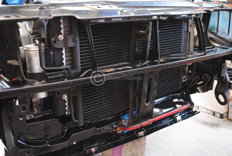
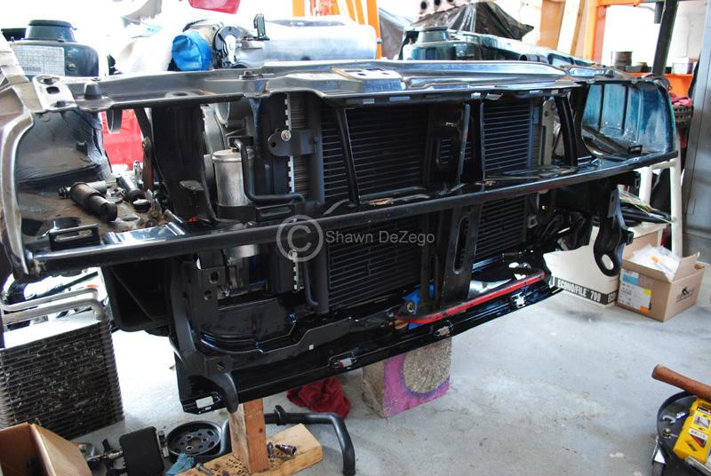
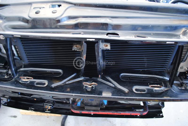
also, FWIW note that someone did a piss poor job adding slots to accommodate the VR grill on the G60. They also had it recessed so the Grill sat flush with the G60 headlights where as if you have the universal VR support like I do (show in prev post) there are accommodations for both grills. However, when using the VR grill slots on the G60, the headlights will appear sunken and not even with the grill. Thus why I switched to VR Lenses and Bezels years back.
Another major difference (and the need for me to absolutely need the VR support (as you will see). the the height difference toward the Pass side of the Rad/Cond pack. Because the VR is much closer to the Grill, the top of the Rad support is heightened all the way up to the Grill.
Here is a side by side comparison of the two from above pics. Note the top of the rad support just the the right of the pass headlight (Vr left and G60 Right).
...so, here was the initial fit up. I said it was big
Notice the cast end tanks and the 2.25" Core? As you will see I needed to gain ever inch from side to side so I needed to shave off those has Ribs, etc. ..and then some. And yes, the inlet and outlets are not in the correct orientation which I was aware of when I chose.
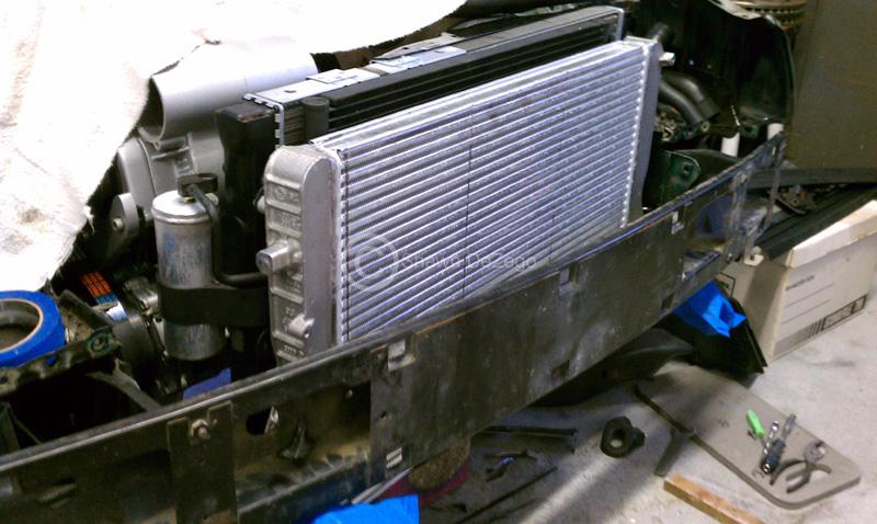
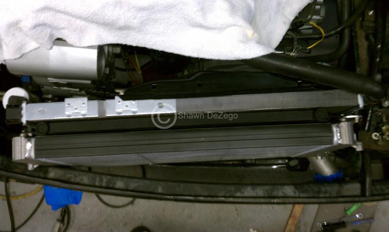
Stock G60 Rad in Factory position with the "G60ing" Spal Fan mod
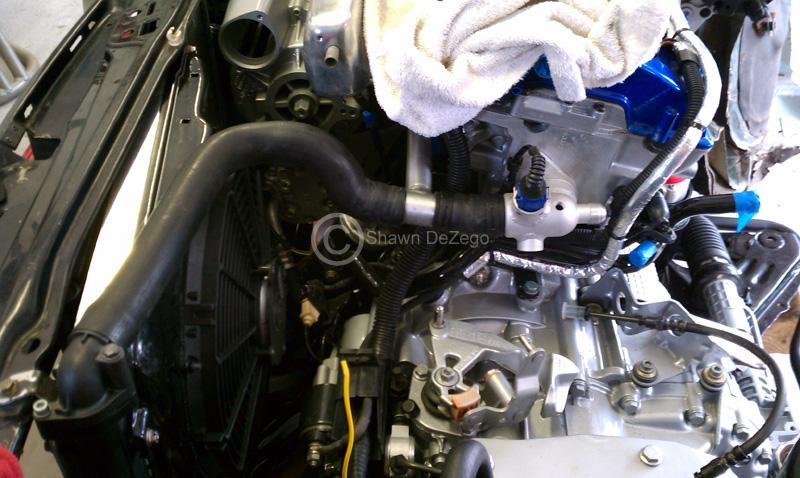
More Pics Notice the clearance on the pass side top? That is partly why the VR support was a must.
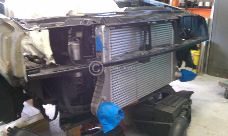
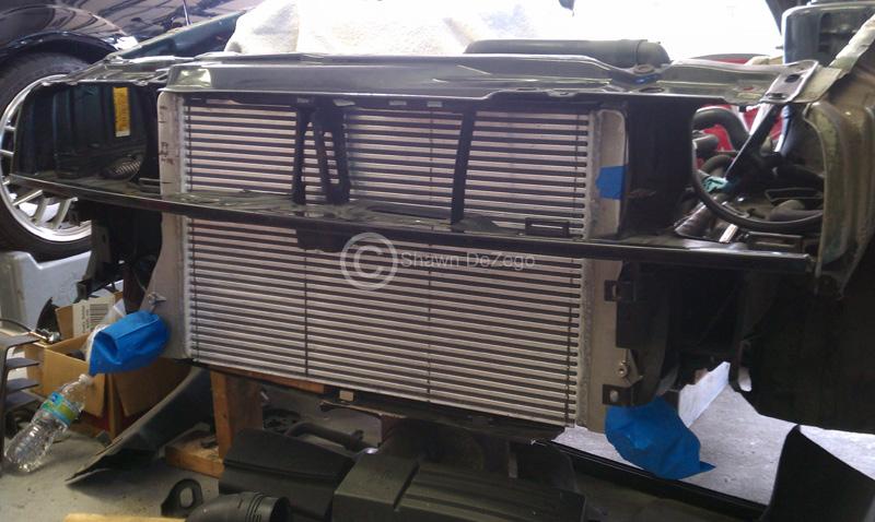
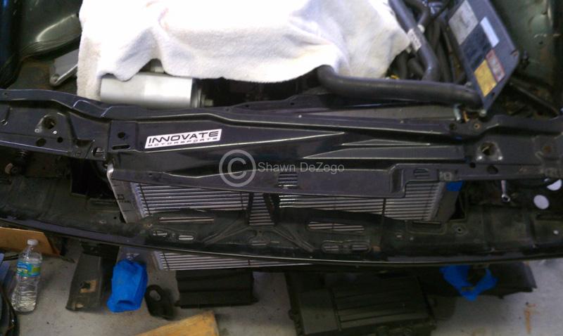
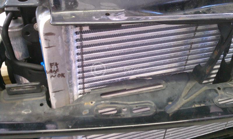
Here is the way every aspect of this whole IC project went... "almost"
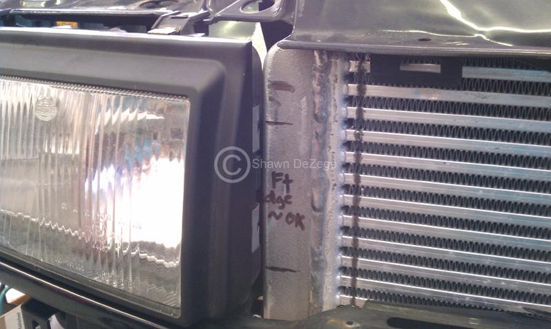
I need to clearance a small section of the End tank to clear the Pass headlight. Even with the shaved castings.
Driver's side is right up to the latch spring, so no room to give.
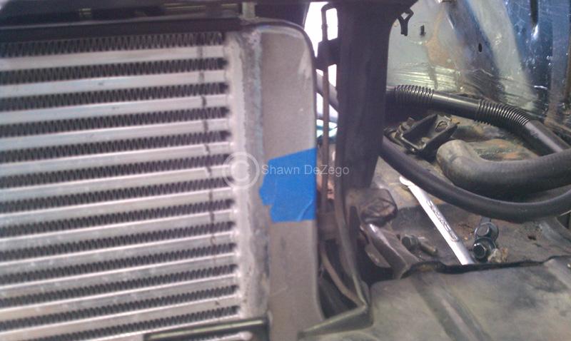
Will post more as I progress.
oh yea, in case you are wondering this is a VAG IC. From a Euro Audi S3 2.0t
It is a Tube/Fin as you may have noticed. There are pros and cons to both Tube/Fin and Bar/Plate IC. I decided this was best since it is basically blocking the Radiator?
I also decided I wanted the IC in front of the Condenser. Great for the IC, but maybe not so much so for the A/C
February 10, 2012
Worked a bit on the IC during Lunch so decided to back the C out and take some finished pics of the Repainted Front, New Bumper Grill, and SFT 70mm lip. I can't say enough about the quality of this product
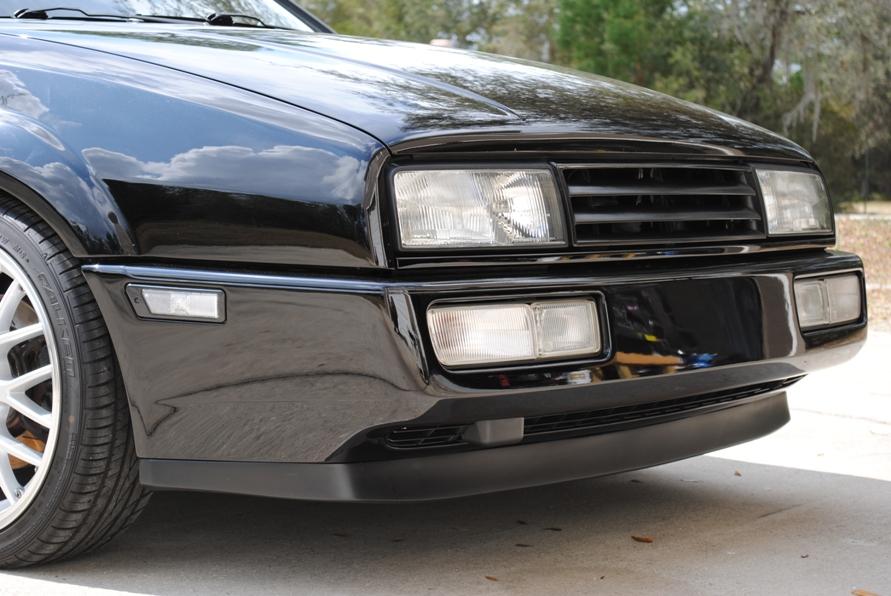
February 25, 2012
I had a bit of time to work on the modifications needed for the IC. I cut off the in/out, Welded up the Sensor ports on the end tanks, moved a section of the end tank ~1/4" to clear the Pass Ecode Headlight and also welded a mount.
Pics are not the best
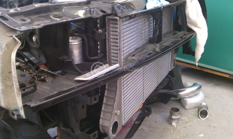
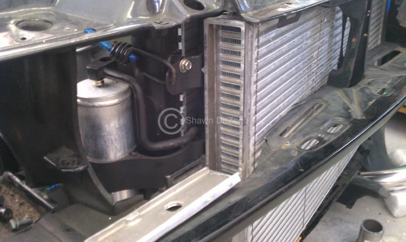
Very pleased with the quality of the core!
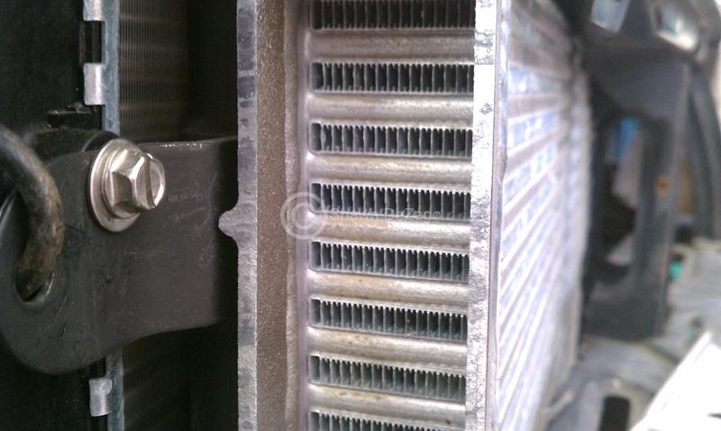
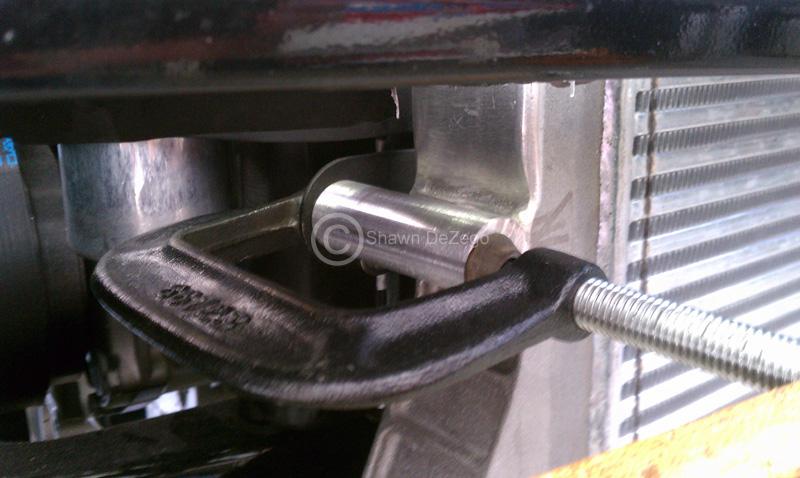
The start
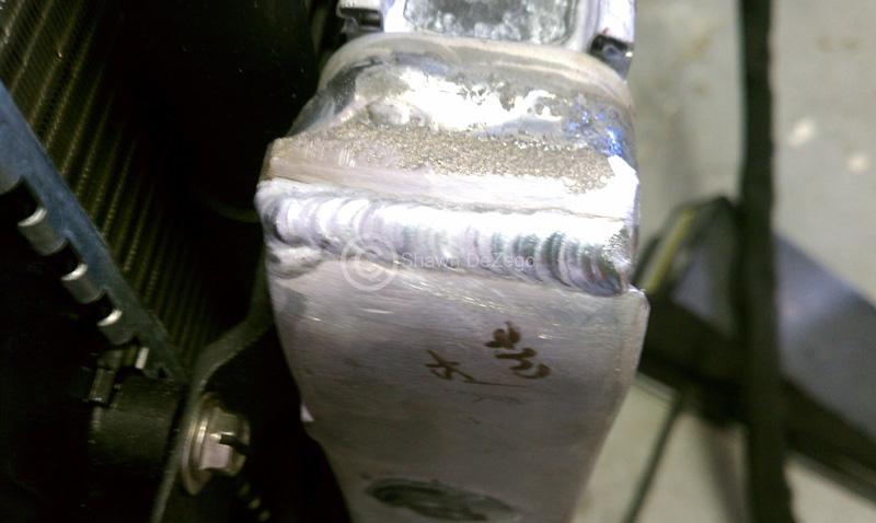
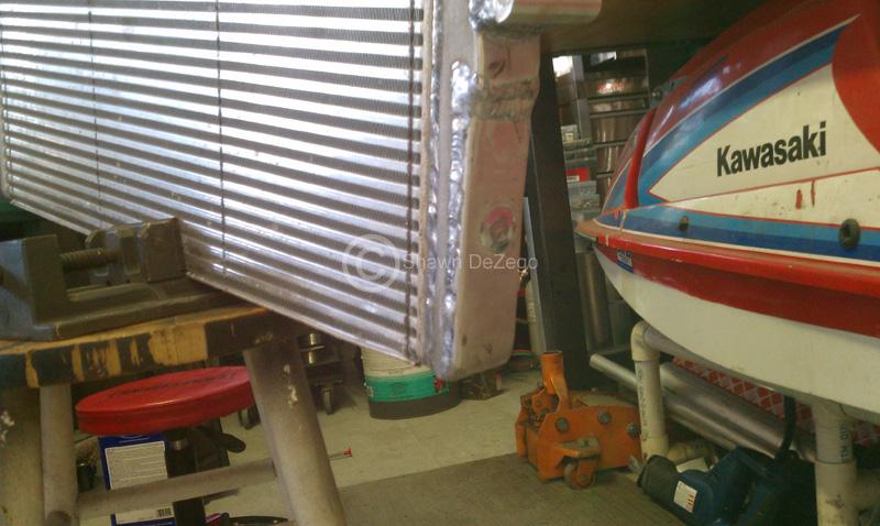
March 04, 2012
Busy week/end, but got a bit to put toward the car.
I spent most of the day Sat cleaning up my garage and organizing (much needed) and it also gave me the gumption to transplant the new full mock bay on top
Just some early mocks on what I have planned for this side of the IC
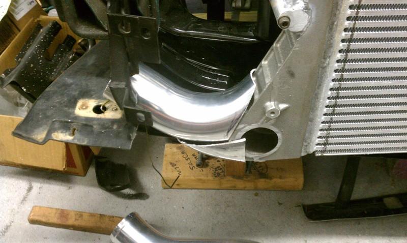
Mock clears everything including brake duct with a tad bit of room for movement. Cut off tow hook area will be reinforced.
New Full Mock Bay
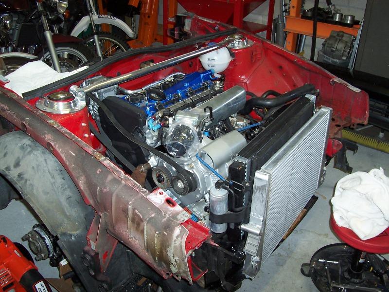
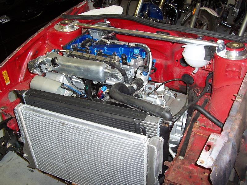
The Alt Clears everything nicely
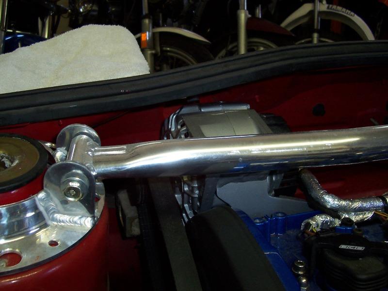
For once, the VW Gods are giving me a pass!! I was really worried about needing to rework the Evaporator and re-orient the Expansion valve based on crude measurements. Well, low and behold, something actually worked in my favor for a change.
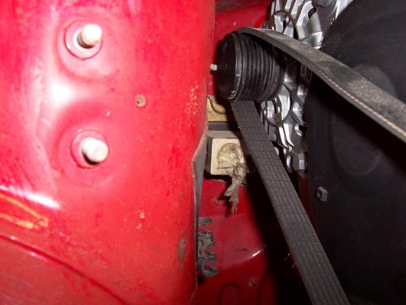
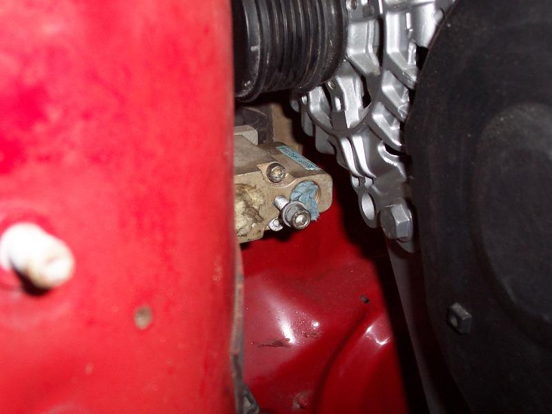
March 15, 2012
Yea, pic is a bit deceiving, but since I will be making custom a/c lines, I make tweak it a few degrees downward anyway, which is no problem and no fear of hurting the evap.
I scrapped some time together to do a bit more in the IC piping and it is coming along nicely albeit a lot of tedious work. I just about have the Pass side done, but here are a few pics during.
I ended up cutting much more off the IC, just because it was easier/better for making smooth transitions. Even though it looks like there is a step transition at the top of that pipe where it meets the IC end tank, the inside is smooth as a baby's butt. The IC End tank is cast with a large rib, which will be ground down before welding to look more eye pleasing.
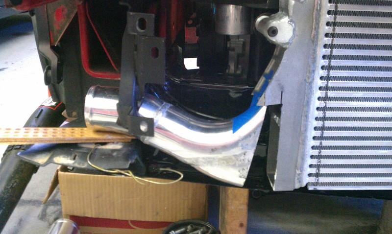
Filler Strip
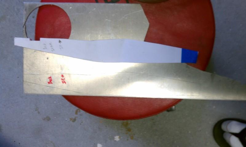
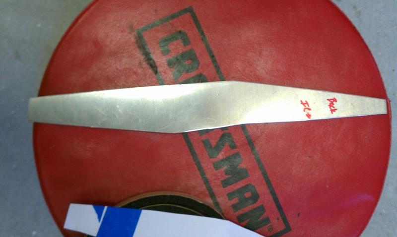
Give you an idea , before shaping and welding.
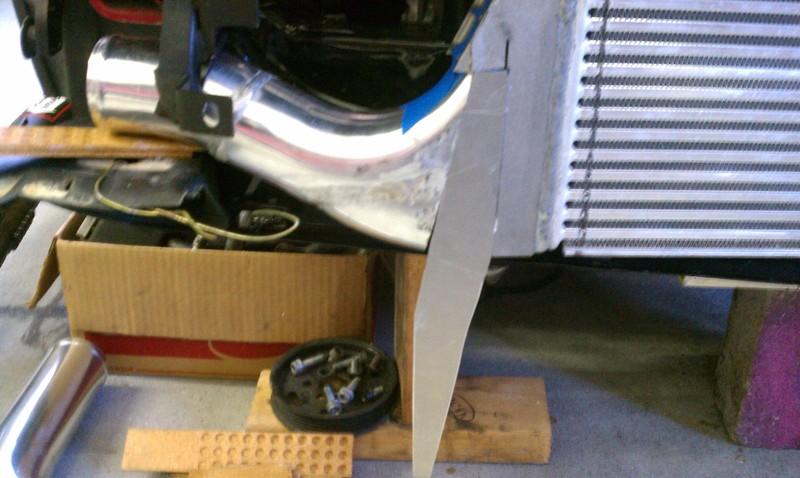
No progress this weekend as I will be in Daytona for Bike week and Races.
March 31, 2012
Spent 2 days figuring out what happened to the Cooling circuit on my TIG , but got it all squared up.
Had a bit of time to finish up the outlet side of the IC, I started mocking up some of the piping and will be starting on the Inlet side of the IC. It is slow progress as usual, but steady.
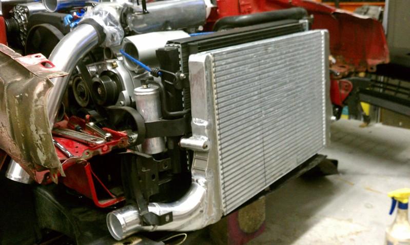
April 01, 2012
Thanks guys. As always, one thing I will remain true to is not cutting corners just to be done with it. I still have quite a bit of work to do, but I can finally see the light at the end of the tunnel.
The best things in life a far from a silly car, although it it would take an act of congress for me to part with my Corrado or my Harley for that matter.
But this was a truly great weekend! I got work done on the Corrado, my son (whom I coach at baseball) Pitched 2 great innings and hit a hard double off of the best pitcher in the little league Majors here, and I taught both my son and daughter to surf today. This, BTW, was at the same beach and very spot that I learned many years ago and then later used to represent my Turbo MKII Scirocco at back in the late '80s. Coincidentally, "The Shark Bite Capital of the world" (New Symrna Beach Inlet) , but who worries about that stuff?
May 14, 2012
Nothing in the last few weeks on this project. $$ Projects always come first.
I did finish up the outlet side though and started on the inlet.
This was my first official AL Intercooler Pipe TIG welding. Not too bad (just a little movement), but room for improvement which happened on weld 2 and 3, etc. Impressed at how the 2mm CXracing pipe welds.
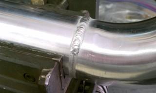
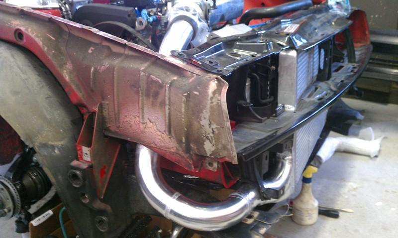
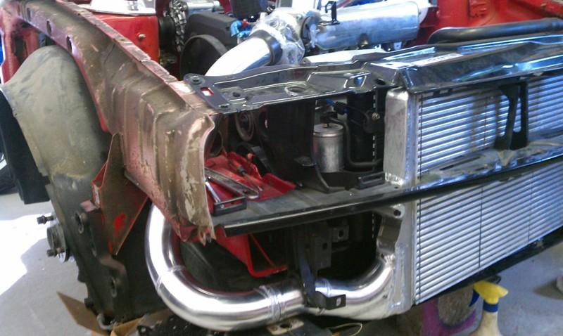
June 21, 2012
I have been super busy with everything under the sun (except the Corrado). Although, I did Buff and wax it and drive it a bit
One of many items that has been keeping me busy is this little girl I picked up. Don't let the fact that looks a bit messy and old fool you. This thing is built like a freaking tank!
I started tearing it apart to inspect, clean and paint. All of the internals look amazing, so it just needs a couple of bushings made on the apron shafts etc, and they are not even really that bad. Really just some TLC and a few things here and there.
Should be fun to have this at the house and not have to travel to my brother's shop to use his mini lathe
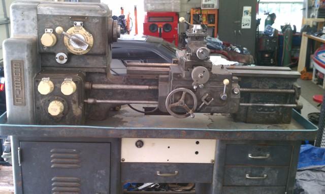
November 06, 2012
The Lathe or the Swap?
Lathe = Yes (almost)
Swap = no, not yet
January 02, 2013
I spent the time off for the holidays working on some paying projects as well as working on my garage (which is slowing becoming a small shop) The Lathe is just now about done and already in use. I also got my small 6x24 benchtop mill back together, mounted and operational which will be very convenient for small mill projects (Bridgeport at my brother's shop for the bigger stuff). Also ordered a bunch of tooling for both machines
Good stuff to come.
January 11, 2013
Pics of the almost done (but currently operational) lathe. I also fabbed up a Chip guard. Just need to make a spur gear to put the whole apron assy back together).
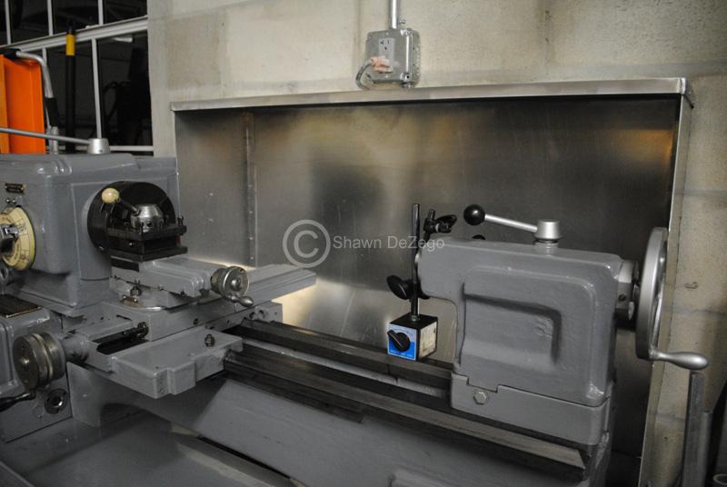
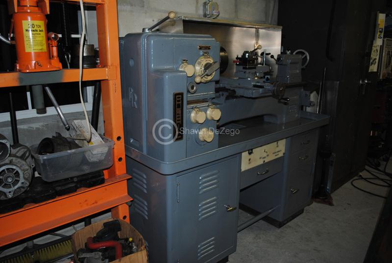
...and my little benchtop mill I got back together. Bridgeport at my brother's shop for the big stuff.
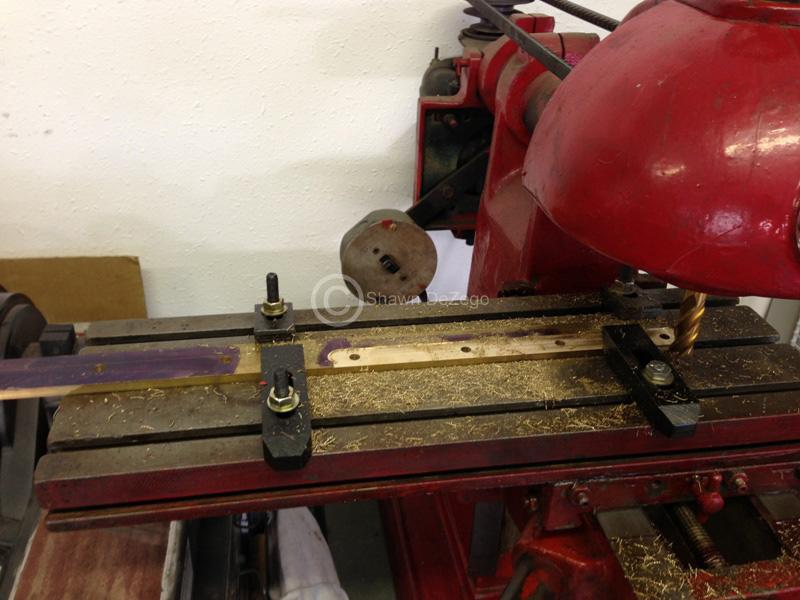
June 09, 2013
ea, it is definitely time for it to be done... I really hope to wrap it up this year.
The good thing, is that I have not given up and work on it weekly, but life has me too busy lately (I am actually ok with that). The Older you get the less time you have to do what you want as opposed to what you "need to do". Wife and kids are priorities as well as work and the house (job in itself). The maintenance alone on 2 Harleys, kids motorcycles, boat and 3 cars is a full time job too. Not to mention the side work I have been doing including continuing to make 02m mounts.
What I have left:
- Rebuild spare G60 charger (already started)
- Finish IC piping (Close)
- Make intake piping and Air Box
- Relocate Batt to Trunk (Likely)
- Finalize A/C lines
- Purchase and mount Oil Cooler in Stock G60 IC duct
- finish remaking the Serp Belt Tensioner (Close)
- Fab work on Header
- MSIII wiring harness
- Misc odds and ends
Then just install it all an tune!@
June 10, 2013
Lest not forget, I am driving my Corrado daily while this is taking place.
I am planning on tapping into that duct for the CAI to the Air box which will be relocated to the Driver's side. approx 6"x7" duct opening in the rear, but the oil cooler doesn't have to be that size obviously.
I spent a week or more hand scraping the ways to get this thing in perfect tune and back to spec. Been using it quite a bit, but still need to make one Spur gear and shaft for the apron gearbox and then will be able to start cutting threads and auto facing. I bought the right gear cutter to use on the bridgeport, but just need to find some time...