You must be logged in to rate content!
94 minute(s) of a 891 minute read
2-18-2013
The bike is more like a pet project.. nothing too serious. I was making pipes for it this weekend. Only put a couple hundred worth of parts into it so far and it's getting near what I want. Once the pipes are done, I'll figure out what to do for a smaller seat and then it'll prettymuch be done.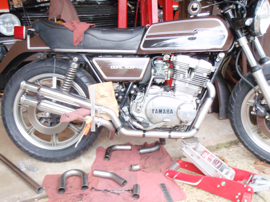
4-1-2013
Not too much to report. Been real busy so haven't spent any time on the car in the last 2 or so months. But finally started on the mini-tub this past weekend. Scraping the old Dynamat off the areas to cut/strip sucked. I got the old tubs out and started trimming the trunk pan back into the framerails to clear room for the new DSE tubs. Don't have too many pics so far.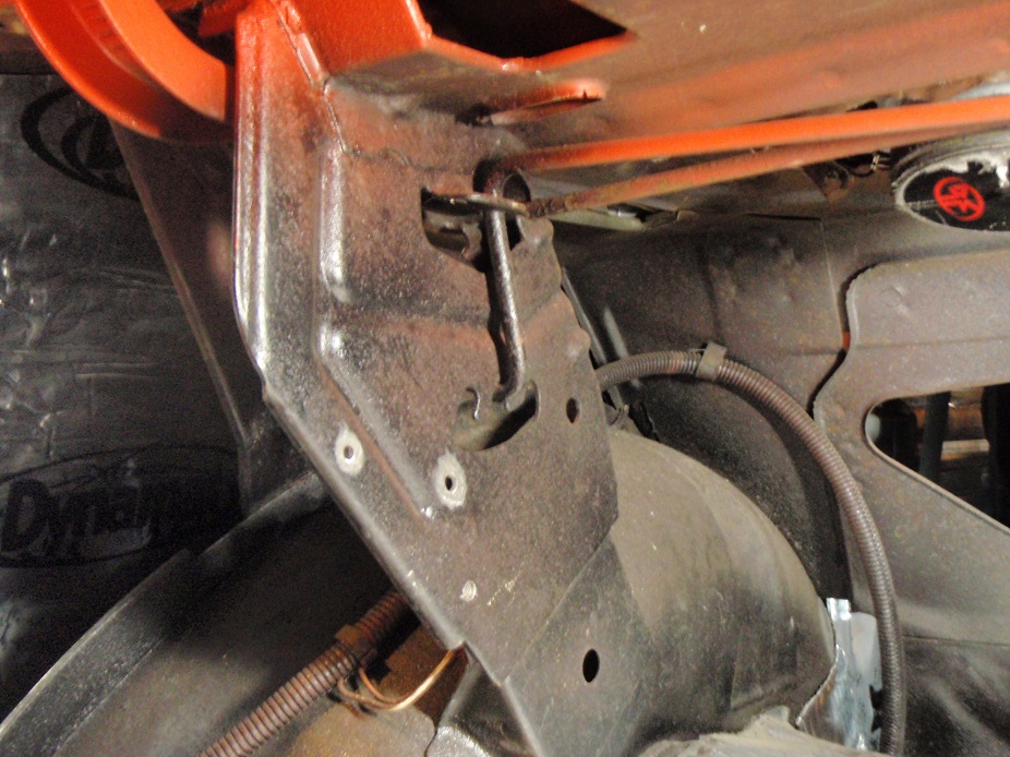
Vice grips on the leg of the torsion bar for more leverage..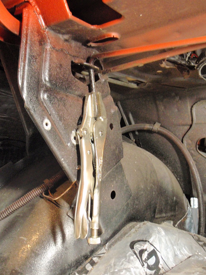
Screwdriver between the top of the torsion bar and underneath the package tray, so push down on the screwdriver to unseat the bottom notch after the vicegrips have been rotated enough to unhook the bar off the top notch (in this case it's clockwise, sorry couldn't make a curvy arrow in MS Paint)..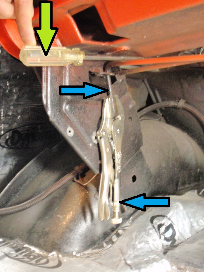
Orientation of the bar un-preload-twisted..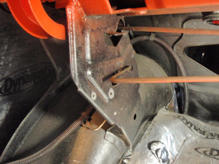
Removing the sound deadening.. annoying...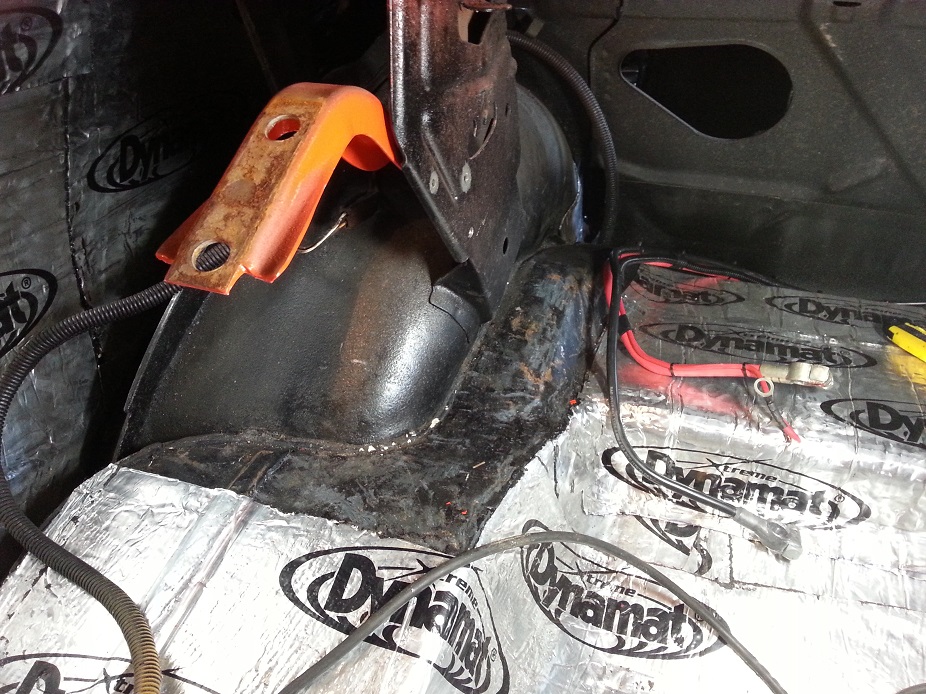
Stripping the paint to find the spot welds to drill out, there were a lot of them on mine, and all over the place..
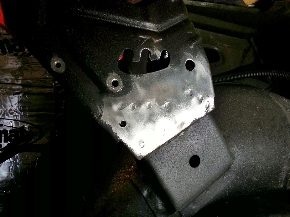
3/8" drill bit seemed the right size to knock out just about all of the spot welds..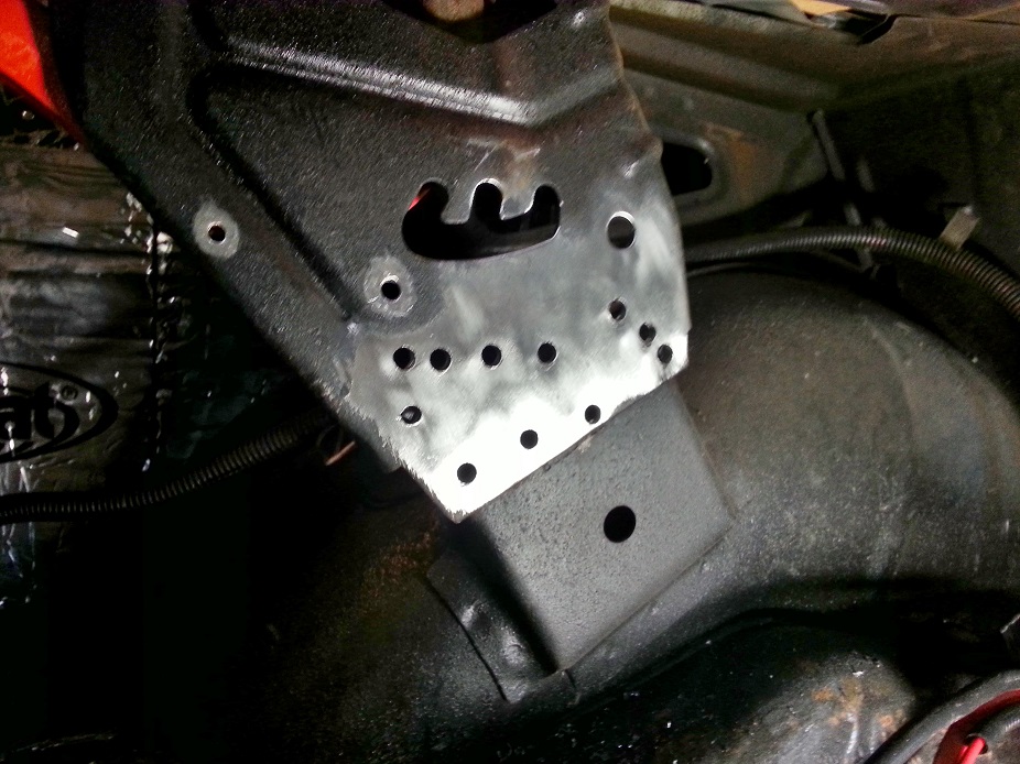
Inner tubs cut out! Definitely no going back now. DSE says to trim the stock tub out of the car right at where the tub joins the floorpan, then scribe a line afterwards that's 2.5" inboard, however with the bulkiness of the only cutting tool I have for the job, my 4.5" angle grinder, I couldn't follow the tub/floorpan joint closely, so I used good masking tape to mark the 2.5" line, then cut the old tubs out however my angle grinder would fit in the tight spaces, then final cut along the 2.5" line once the tube was out and there was more room to work in.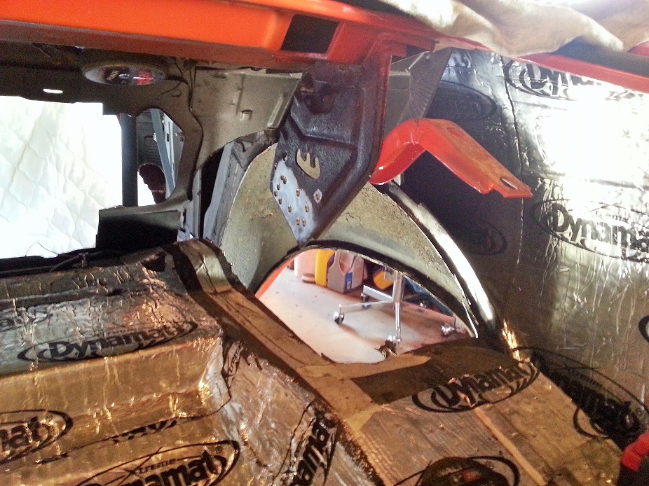
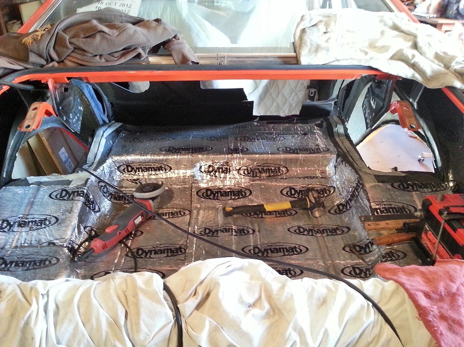
4-21-2013
Here's a teaser. Cutting has been slow, the DSE instructions are quite vague, and I'm finding most the templates need massaging for my use. Have tons of pics and going to scan & make PDF's of the templates I made up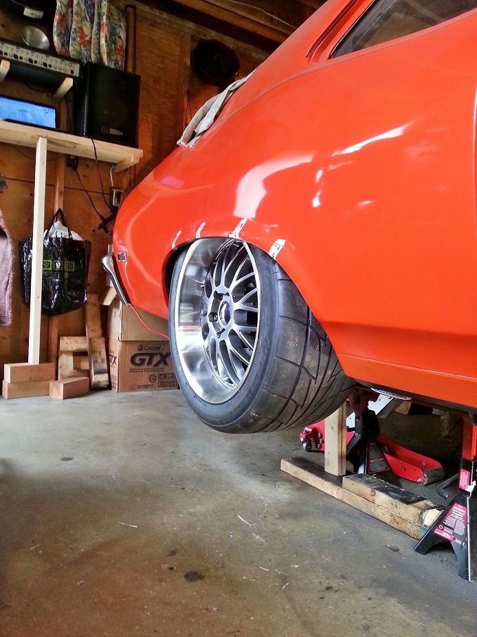
4-22-2013
Their instructions aren't terrible, just not great. It's a 1-page sheet and a DVD.. of which is shot in a small resolution and the shots of what needs to be trimmed and where are quick.. so it's hard trying to pause it and decipher lines on a grainy/pixelized freezeframe. I ended up just giving up and doing all the exploratory cutting myself. I appreciate the offer of assistance, and will take you up on it if I hit any snags, but so far things are lining up well, just taking forever to trim little bits at a time so I don't have to make any unnecessary patch panels.
At my (arguably lower than most) ride height (tucking 1.5" of 18" rim in the back), with a wheel spacer, my 305 sidewall has 1/2" clearance to the outer fenderwell, and there's a decent inch at least of room between the inner tire sidewall and the mocked-up DSE tub. From the looks of it, a 335 should fit, but might rub under hard body roll and bump. A 315 would be a breeze to fit and shouldn't rub under any conditions. I've cut into the framerails considerably, but am happy with how the bracing is turning out.
They provide templates via a PDF you have to print out, but I noticed several of the bits, particularly the sheetmetal closeup panel between the framerail and the over-axle-trunk-floor-hump didn't offer full metal coverage. I purchased the setup knowing that I was in it for the stamped tubs, and anything more than that would be extra. You have to cut out all the metal bits yourself, and so I'm ok with making my own templates anyways, as I didn't end up cutting the metal to DSE's spec, as well as the car-to-car variance can get pretty decent I bet.
And turns out there was some rust that was almost exclusive to the inner tubs, on both sides. So even if I were to go thru all the extra effort of precise initial cutting in an effort to keep the stock tubs reusable, I'd have to repair them, not to mention clean it all up, which would've been a pain. My patience is wearing thin the longer I work on these things, haha.
4-25-2013
This was me for far too many hours last weekend. Hope to continue the progress this coming up weekend. 6'2" bodies are not meant to fit in there...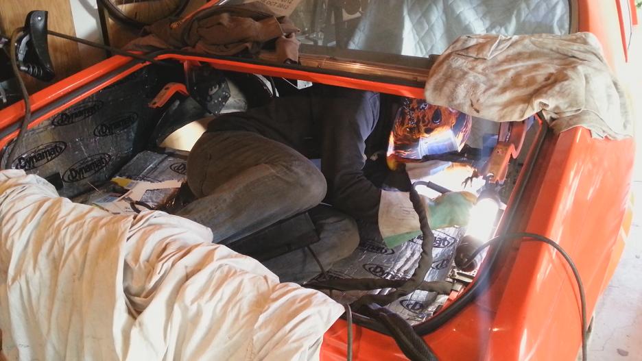
4-30-2013
Haha Greg, I would've loved to join the cruise rain or shine, but I have an excuse, and at least I used the rainy weather to get some 'garage chores' done!
Made more progress. In one day, went from rough-cut-out of driver side stock wheel tub to a fully finish-trimmed area, just awaiting wire-wheel cleaning, framerail gusset welded in, and then final install and spot weld together.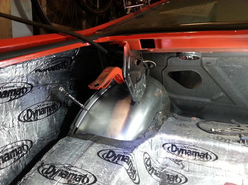
5-5-2013
That gap at the bottom is present with the flange flush as well as the arch of the fender tub flush (altho in that pic it's just rough mocked, not full flush). Have to make a closeup piece to cover that gap as well as cover about 6" below the bottom of the DSE fender, to close up the quarterpanel area behind the wheel. Kind of surprising DSE doesn't supply a template for this closeout piece.. maybe I just cut out more than I was supposed to behind the wheel and below the trunk pan.. will never know as DSE doesn't clarify that area at all in their instructions.
On another note, passenger side is fully welded in and awaiting seam sealer and paint tomorrow.
5-6-2013
The sealant I'm using is a Permatex body sealant, supposed to be quite flexible when dry. For paint, going to use auto store wheel well underlining, don't know too much about it but the wheel tubs will get covered in rubber and dirt anyways.
After a lot of hammering and fitment it does look at home all welded in there. I've noticed that the rear half of the flange sits nice and flush with the existing factory [outer] tub flange, but the front half (essentially from the seat/trunk bulkhead forward) there was a consistent 1/4" to 3/8" gap that I had to hammer/stretch flush in order to spot weld the DSE flange. This was consistent on driver and passenger side DSE tubs, so not sure if I was cutting incorrectly or if the DSE tub is stamped slightly off.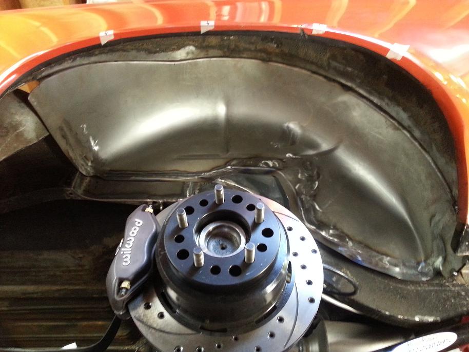
After a total of probably 30 sweaty hours into it to get it to this point (passenger side done, driver side needs weld in of 1 closeout panel then wheel tub is good to go in).. I would never do this or any other sheetmetal work for another person (even if paid), and I'd be borderline on doing it again to a car I owned in the future. Looking forward to just driving it already, hah.
And Mark, you missed a good thighmaster session yesterday...
5-13-2013
Tank doesn't need to be modified for the mini-tub setup, however it is recommended to dog-ear it for tailpipe clearance. The necessity of this mod is all subjective, depends on how wide the tires are that went on, how big diameter the tailpipes are, how well-fitting the tailpipes are (generic pre-bent or custom cut & welded), and also how low the car is.
Since my car is pretty slammed, and I don't like the idea of tailpipes heating up my gas tank, I already dog-eared my tank, although I think I snipped a bit more than necessary. Oh well. Here is the modified tank: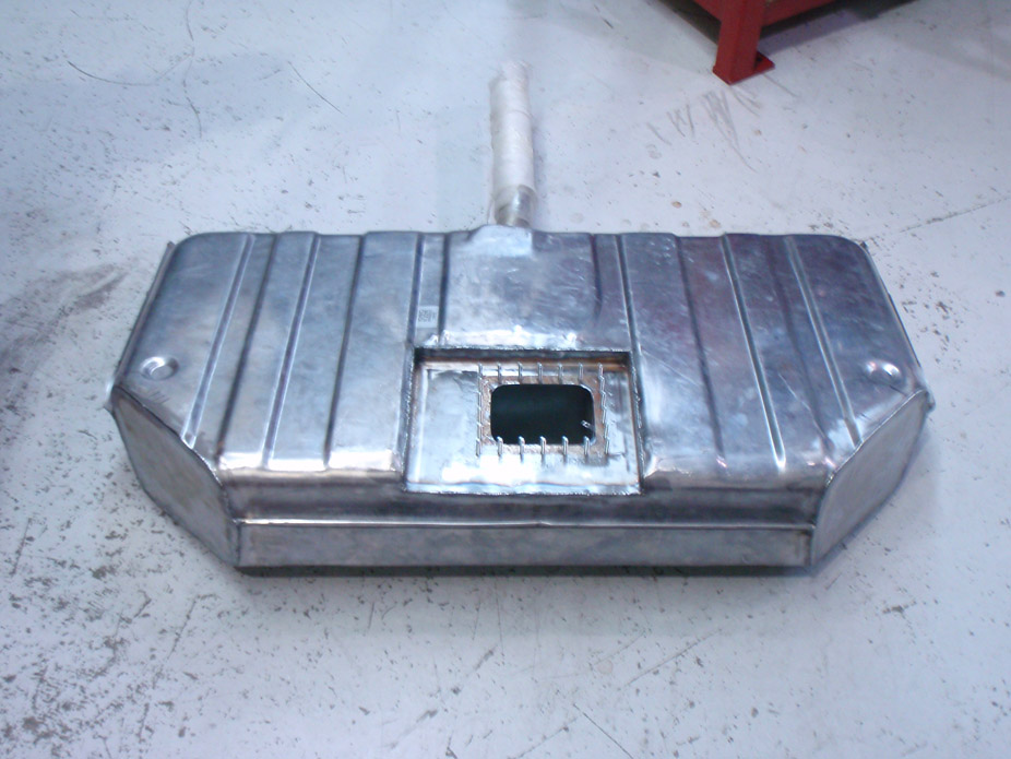
I finished the mini-tub yesterday, it's all welded, seam sealed, and ready for paint tonight, and hopefully will make good progress on tailpipes this week, next weekend. We need to emissions test up here, and they need exhaust to go to the perimeter of the car in order to test with their sniffers, so these tailpipes need to get made before I can lower the car on the ground for good and drive. I want to start off driving it with full insurance & plates... getting 1-day temporary permits in the fall to drive it got old real quick.
5-17-2013
Mini-tubbing is done, wheel widening is done and mounted, the roadblock currently before lowering the car to rubber is the over-axle tailpipes, which need a gas tank put back in there before I can start cutting/mocking those up, and before the tank goes back up, I wanted to redo the fuel pump wiringpass-thru, which I'll show below..
Wanted to go a fully-sealed design, so used a steel bulkhead fitting, a Delrin insert, and #8 studs for positive and negative connections..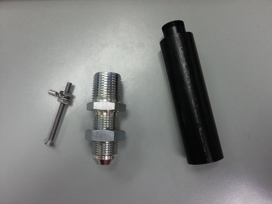
Bulkhead fitting before trimming/boring..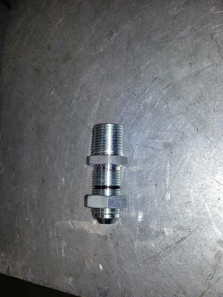
Bulkhead fitting after trimming height, boring the ID, and also the Delrin insert which will be epoxied into the steel bulkhead fitting, and the #8 studs will be epoxied into the insert. The heights are offset to increase the gap between positive/negative terminals. Once the wire terminals are tightened down, each terminal will be coated in a gas-friendly, non-conducting sealer to further eliminate the chance of sparking/arc'ing.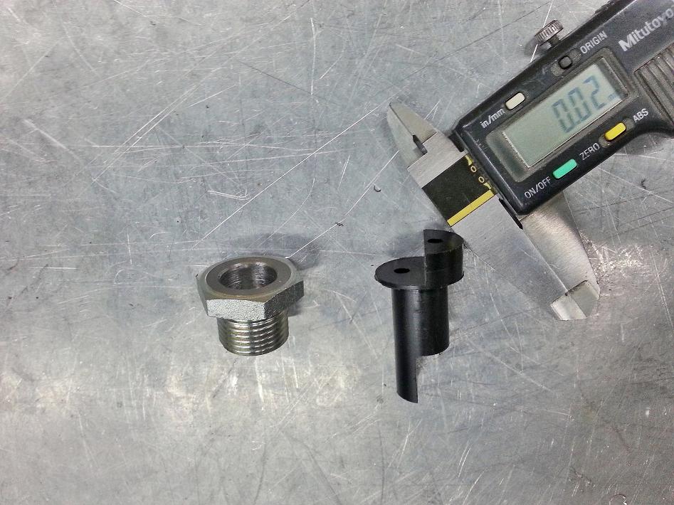
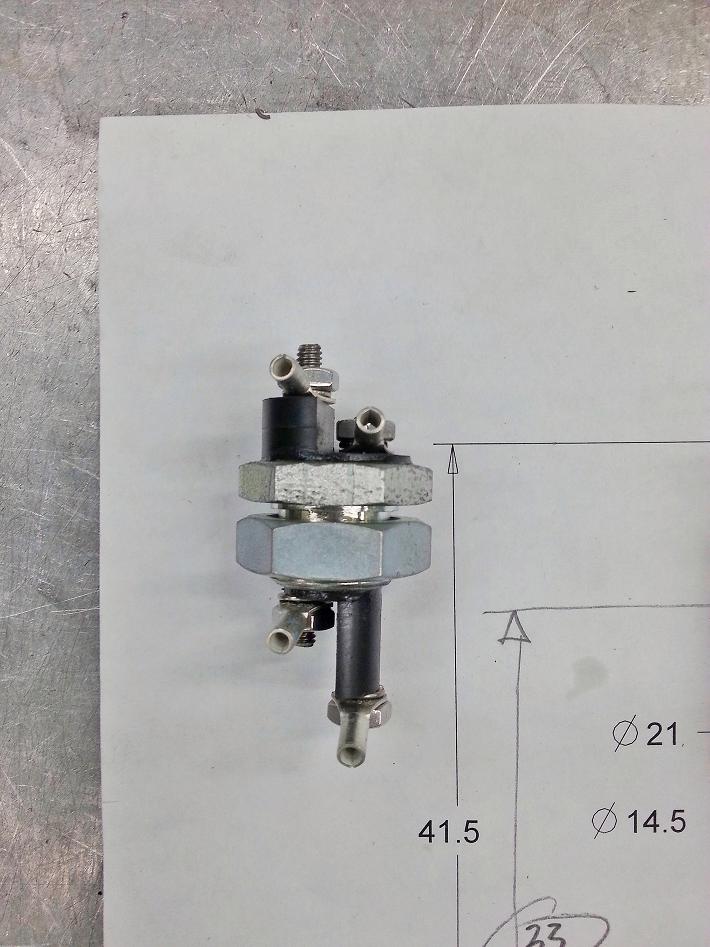
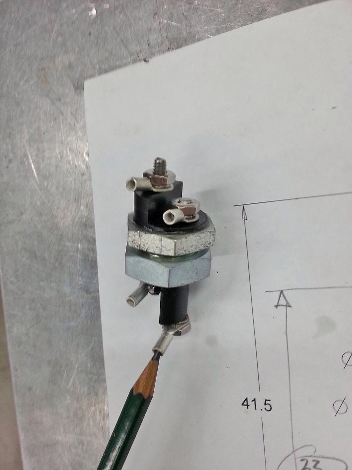
Also was welding some v-band flanges onto the mufflers so I can hit the ground running on Saturday morning regarding tailpipe making, and got to try out the new shop welder for the first time. This thing is a beast, it makes my home Dynasty look like a fluxcore mig welder...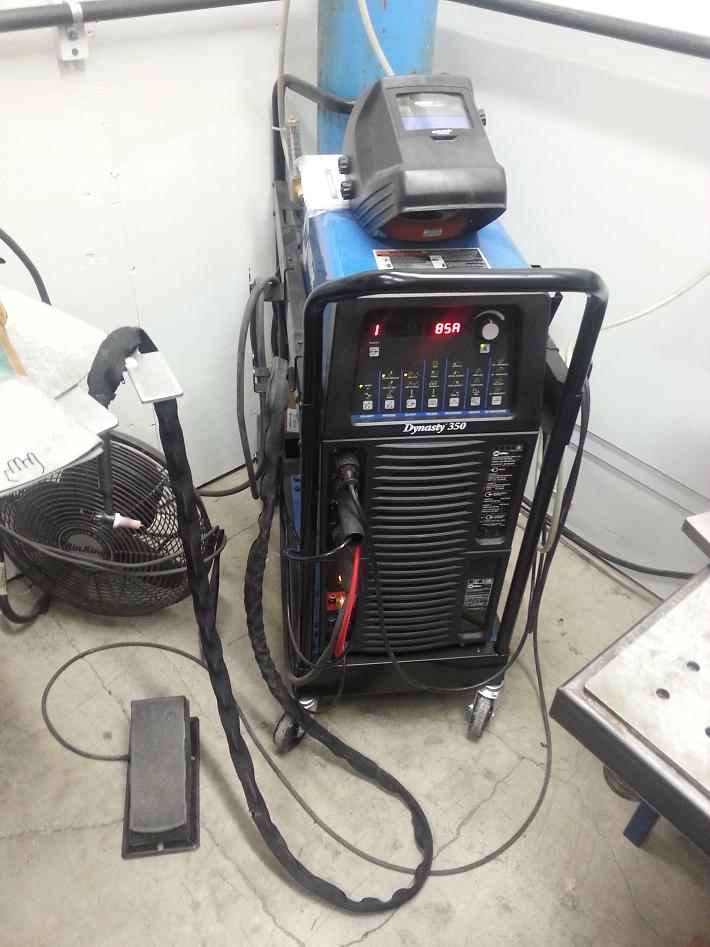
6-2-2013
Mini-tub is officially done. At full compression (on bumpstops) have 3/8" clearance between outer tiresidewall and outer inner fender well, and a good 1.25" of room for tire growth for inner tire sidewall.
Made some tailpipes yesterday that I'll finish weld at work tomorrow night, and also have to shorten the front swaybar end links, and then it's ready to roll.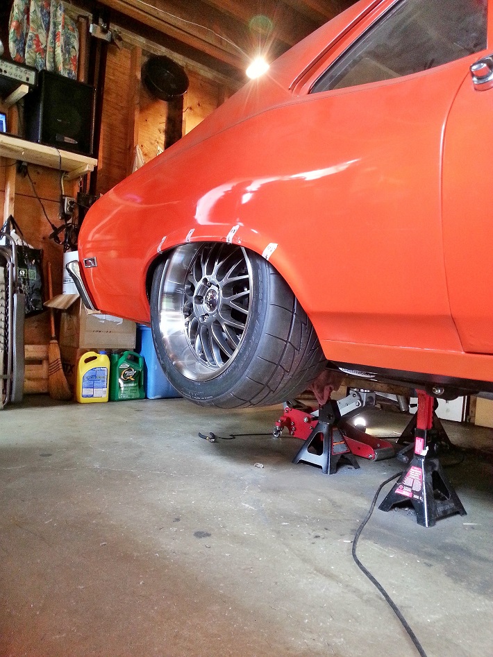
6-3-2013
Not finished but I think they look kinda cool. First attempt at making over-axle tailpipes. Room was very tight but it clears everything with a good 1.5" clearance, and lots of heat wrap will be used for fuel lines.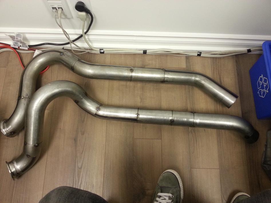
6-5-2013
On the ground. Needs trunk lid back on then ready to drive. Hoping the new springs sag ideally 1 inch, but will settle (pardon the pun, har har) for any amount of sag.. sitting a bit high right now..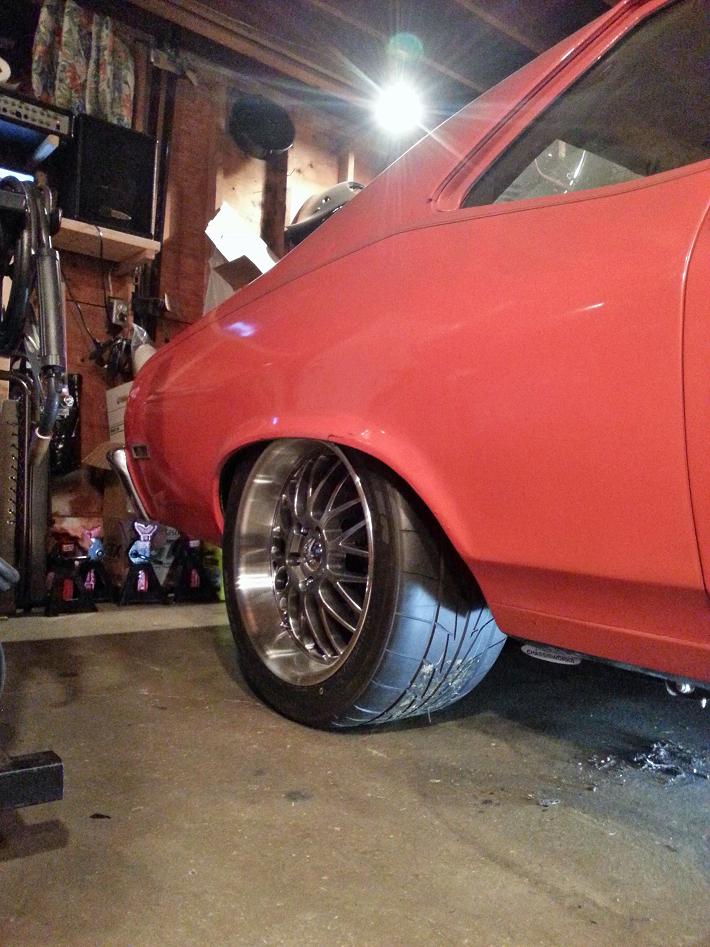
Definitely want to take it on the road course once I'm comfortable with it and the kins are worked out, will crash some of the local import auto-x's, maybe dragstrip once just for *****, but mainly a fun street car...
6-6-2013
On the ground, ready to drive. Except.. the ******* thing won't fire. Cranks forever, gets good fuel pressure, proper injector pulse, MAP sensor reads maxed out. I have a hard time believing the MAP sensor went screwy since the last time I drive it and it was working fine. Going to go hunting for grounds, but this goddamn thing is really starting to **** me off. Could also be a bad PCM since I'm not getting a MIL light, tach, or speedo outputs from the PCM.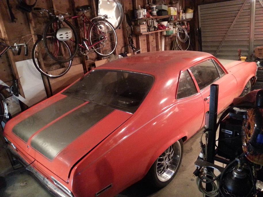
Only happened once. Was driving, **** went super rich, turned it off. HPtuners scanner confirmed injectors were flowing high because MAP reading was 193kpa. Did a Reflash Write and it was fine after. Now, despite Quick Write or Write Entire, it still reads maxed MAP pressure. With the MAP sensor disconnected it reads 90kpa. Something has always been suspect with the setup because none of my gauges that are hooked up to the PCM pin outs read anything. MIL light test doesnt work, speedo doesn't work, tach doesn't work. In HPtuners tho, tach/speedo read and display accurately. I wonder if there's some circuit that at some point got fried and it's contributing to a spotty ground for the MAP sensor as well as not letting the gauge outputs work. *****.
7-3-2013
I made all my own templates, was just easier than fiddling with DSE's templates AKA watching & re-watching the video to try and figure out exact placement. I like to trim to fit for my own application so it's 100% under my control.
I've been procrastinating making a how-to instruction on my mini-tub. I did take pics of everything.
I essentially cut all the way thru the framerail, leaving about 1/4" of thickness left, or about 1/8" gap between the inside of the inner frame rail vertical wall and the backside of where the reinforcement gusset plate wall would end up. I can't find the photos on my phone so will check my desktop when I get home tonight.
So close but so far, on the ground but just won't fire..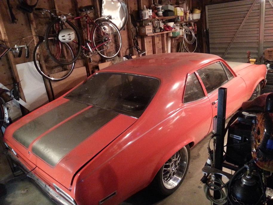
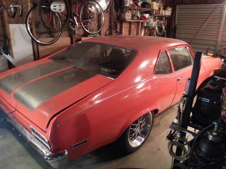
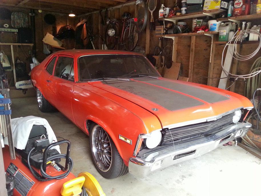
What a good buddy, Mark came by to help out..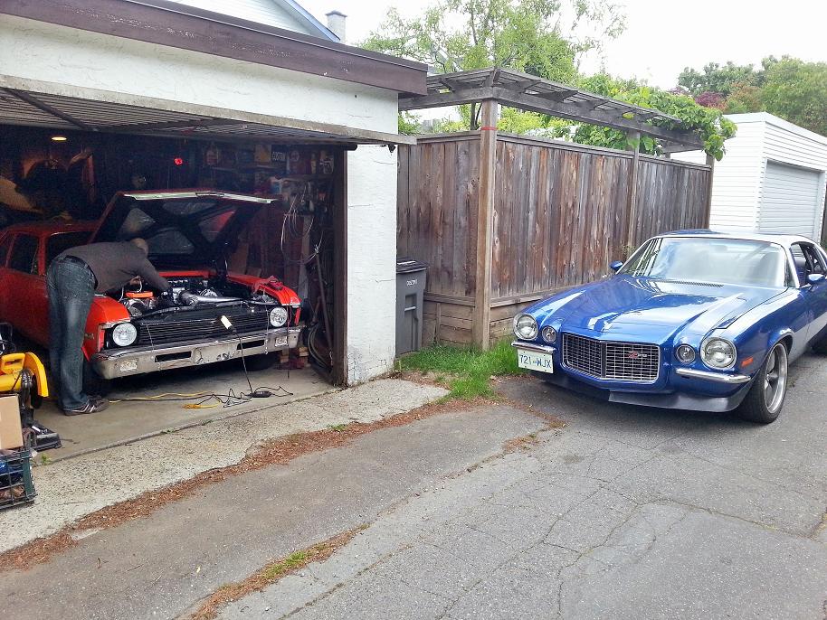
The MAP sensor on the harness side wasn't getting a ground, so I checked all engine/body/PCM grounds and found this block-to-subframe ground that I had "soldered", at least so I thought..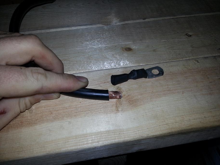
After verifying all hard grounds were good, the MAP plug was still not getting a ground, giving the PCM (as read thru HPTuners) an inconsistent signal and more often than not a max-MAP reading regardless of all other conditions. This (I'm hoping) is the reason for why the injector pulse width was maxed out for cranking, and was flooding the cylinders so bad that the plugs were dripping wet and wouldn't even spark.I've always had a suspicion that my PCM has voodoo devils of fuckitude in it, and so cracked it open..
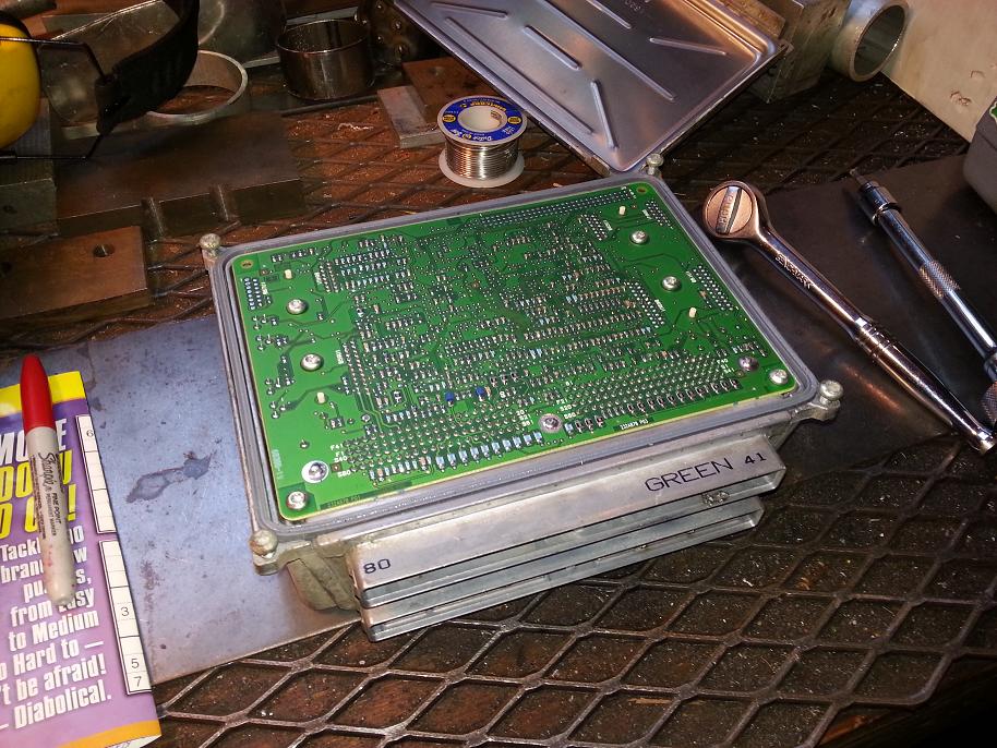
Found this guy. Again, supposed to be soldered but it obviously isn't. Conveniently, it's the ground reference pin for the MAP sensor plug..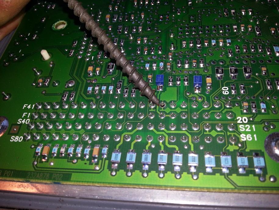
Investigating the plug pins, found some more screwy stuff. All pins that are pushed out/charred are for PCM grounds. I think there was a weird back charge early on that fried the ground pin connections, so that during one of the several times that I unplugged/re-plugged the harness-PCM plugs, the pins wouldn't re-insert in the plugs and got pushed out..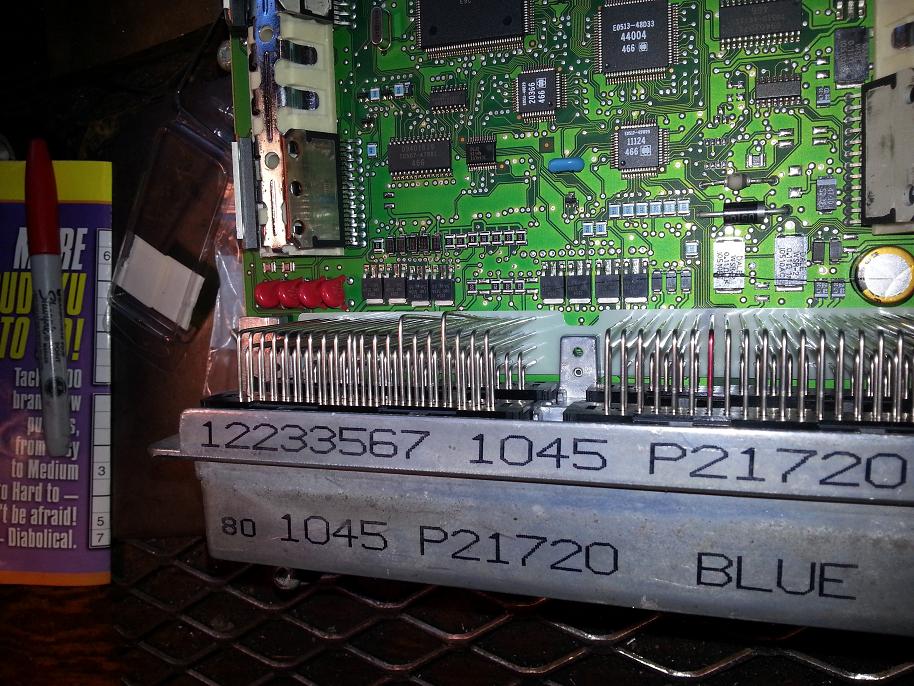
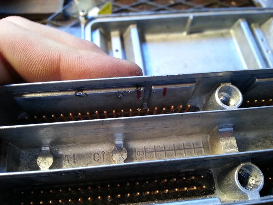
Adding to this, when I check ground connectivity when HPTuners is linked up, and force-on the MIL light, the output pin does not get a ground, so I'm just going to junk this PCM and start over. Hopefully that allows it to start, as well as fixes my no-TACH-output, no-speedo-output, and no-MIL-light-ouput from the PCM.
I found a known-good PCM locally and am going to try to run it as-is, not flashed, this weekend, to see if it gives a correct injector pulse width during start-up cranking. Also going to check all the harness plug pins and re-pin the charred ground ones from the spare truck harness I have lying around. If HPtuners reads a correct (for stock truck tune) cranking injector pulse width, then I'll buy extra HPtuners credits, load my last known-good tune onto it, and hope for the best. Wish me luck.
Parts list for... engine swap? Or engine rebuild?
If you mean swap, here is the link to the pdf..
http://ls1tech.com/forums/attachment...osts-tally.pdf
Here's my parts list for the CAR..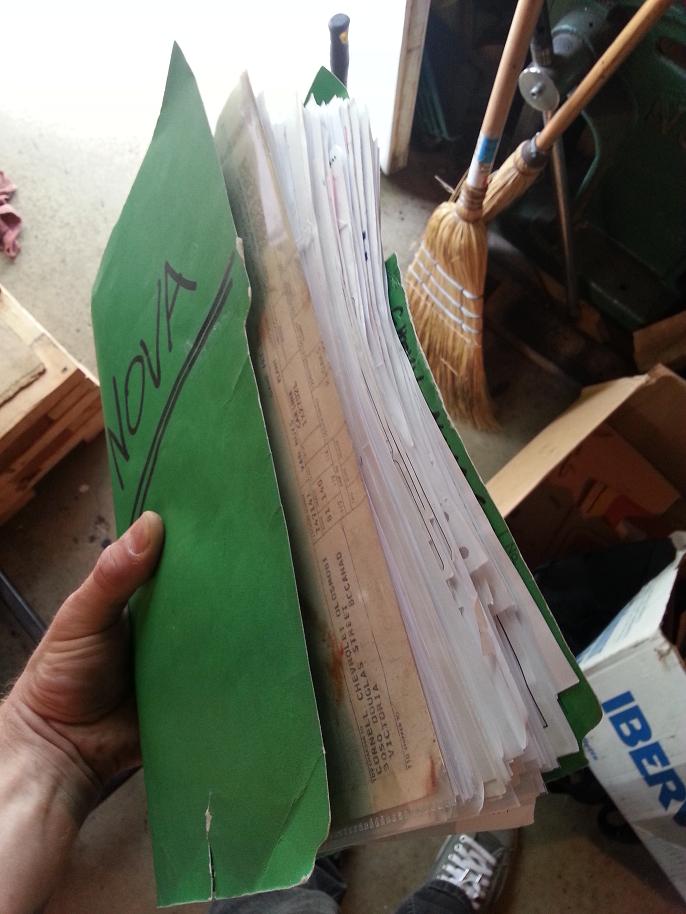
7-5-2013
Sorry for the delay.. here's a pic showing the extent of the passenger side framerail cutting..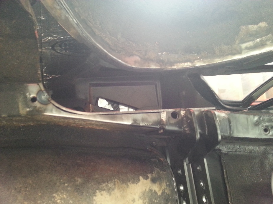
8-14-2013
Wow looks like I forgot about this thread.
LOQ72NOVA.. the holed piece is the shock cross-member for my Glink rear suspension.
Small update, car still isn't running:
- got a 2nd "known good" (Mark heard it running in a van) PCM & plugged that in with zero tuning, car did identical wide-open injector pulse width no start
- measured continuity of all grounds on harness, all good
- inspected all grounding points, sanded fresh
- measured voltages/grounds for all harness wires @ PCM w/ harness connected to PCM (that sucked)
- cross-checked above w/ wiring diagram, appeared that all sensors needing 5V were getting it, ref grnd getting it, appropriate 12V all present.
- inspected HPtuners scans for PID inputs & behaviours when cranking, it appears that following sensors with scanner inputs were all good: MAP, IAT, ECT, RPM, O2's
- only sensor I couldn't check was VSS
- started unplugging each sensor one-by-one to see what, if anything, affected the scan
- got to TAC module, stupidly unplugged that, turns out that BRICKS the PCM if power is given to the PCM without TAC module connected.. oops
- when tried to start after reconnecting TAC, get a P0606 "internal PCM fault" DTC, as well as a P0207 (if my memory is correct) "TAC module error"
- remembered that at some point something physically fried the PCM (un-soldered connections, charred bits), so I'm thinking that charge could've back-traced its way into the TAC module as well, giving it some faulty reading that wasn't indicated by either a measured pin voltage or Throttle Positionon the scanner.
New "tested" TAC module & PCM on the way, hopefully that sheds some new progress... so I see this is why they invented beer!
8-24-2013
New PCM works.. haven't bricked it yet. New TAC module (from '06 Sierra) hooks up but doesn't acknowledge my '05 DBW pedal signal and thus doesn't actuate the TB. Switched back to original TAC module with new PCM, TB responds normally. Stock tune on 3rd PCM does identical problem (rich commanded AFR).. so it's a sensor or wire issue. I believe I may have found the problem tho. TAC module/DBW pedal control the throttlebody properly, as in TB butterfly is barely cracked open at 0% pedal, and opens fully at WOT, however both Throttle Position Sensors on the TB read 1.17V/1.03V at closed, and 3.53V/3.50V at WOT.. so there's definitely something screwy with the position sensors. Kindof very strange for both to be bad. Wonder if something physical in the rotating sensor bit got screwed causing both sensor pickups to be offset/bad. Voltages were measured against both a known-good ground as well as the reference low voltage lines, and the 5V reference power lines measure a good 5V.
Getting real tired of this car's ****, it's getting costly with 2 new PCM's, 2 sets of HPTuner credits for the their VIN's, as well as a (apparently unnecessary) new TAC module, and now a new throttlebody. Everybody fingers crossed this does the trick.
9-23-2013
Nothing new with the car. A while back I probed all the harness pins and recorded the voltages or grounds for all 160 harness-PCM pin connections. This past weekend I started labeling what each measured reading actually corresponds to on the wiring diagram, so I can see what voltage was meant for what sensor, etc, but then gave up. I've reached the limit of the minimal-teardown diagnosing I can do... time to pull the full harness and inspect each wire, inch-by-inch. There's something physically screwy, and all the sensors I confirmed work by reading them on the computer. This'll end up being a fall/winter project. I'm now focusing on getting my motorbike back on the road to enjoy what little nice weather we likely have left.
9-24-2013
It would be great if I had an extra harness, that's actually a really good idea. Is yours a mod'd stock or aftermarket harness? I could bench test a different harness in the engine bay (does that make it hood-testing? haha) if it's just as simple as a constant 12V, switched 12V, and chassis ground, then I'd try that before I'd de-loom it and strip it all apart. At the same time, there's something screwy with my harness and to fix and re-use it, I still have to pull the whole thing to inspect it.
My old stock harness has been pillaged to bits, but maybe I'll wait for you to pull yours. This thing isn't going to be driven until this is fixed, and there's no longer a big rush because the weather will be **** for the next bunch of months. I'll look into the shipping cost both ways if you can PM me you location. If it's not too bad I might just do that. But we'll be in touch regarding it.
I haven't ripped anything out yet so I'll have to check if at cranking the TB is just barely cracked open AKA idle, or if it is opened a fair amount for increased airflow, I can't remember. If it's just idle or barely cracked, I could leave DBW TB in place or hold it slightly open. I'm just wondering what happens on the PCM side when it doesn't get a complete circuit from the servo, only gets a TPS signal. That's if the '02 LS plug even connects to my DBW TB.. which I highly doubt it would. Likely still have to connect an LS1 TB, maybe see if I can borrow an LS1 one from somewhere. I'll look into it.
11-25-2013
Nope no progress. Needed to take a couple months off from it. Re-motivated now to get working on it but have been sick the last couple weekends so no go on garage time. Decided to pull the full harness and inspect every wire inch-by-inch to see what's up. Started a good chunk of it under the hood a couple weekends ago and hoping this coming weekend to crawl under the dash and fish it all thru the firewall.
Earlier in the fall when I needed the break, I got another thing to tinker with. W250 4x4 5spd no rust, intercooled 12V all mechanical... direct opposite of the Nova. Partly out of frustration of the wiringissues, but mainly because awesome.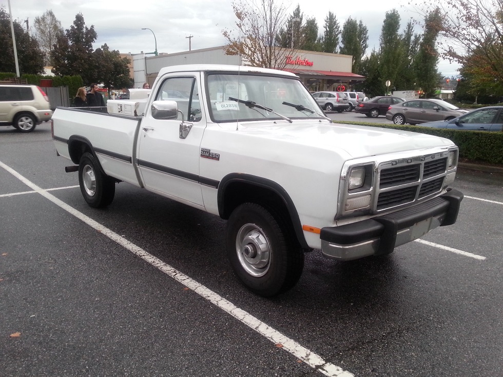
12-12-2013
Thanks for the encouraging words! I'm no longer discouraged, been long enough. I know I'll get it fixed eventually.. just that day can't come soon enough.
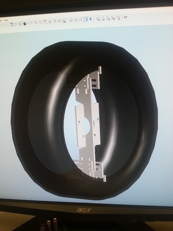
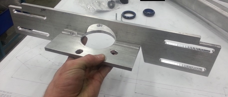
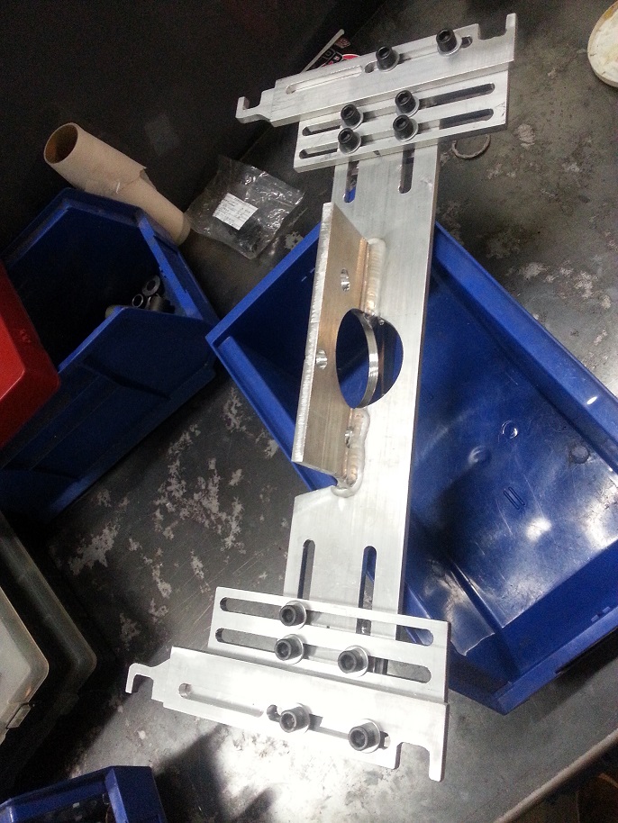
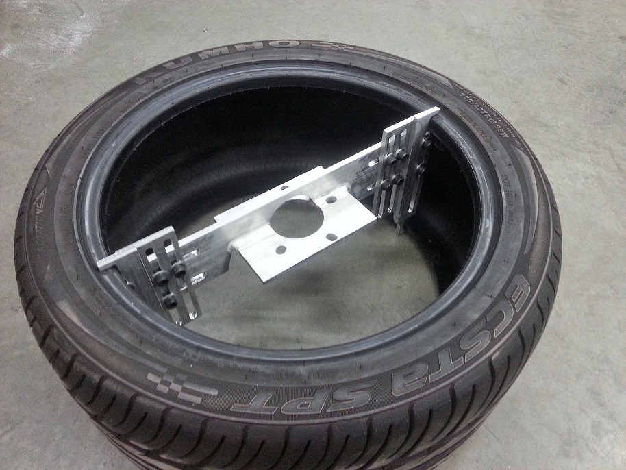
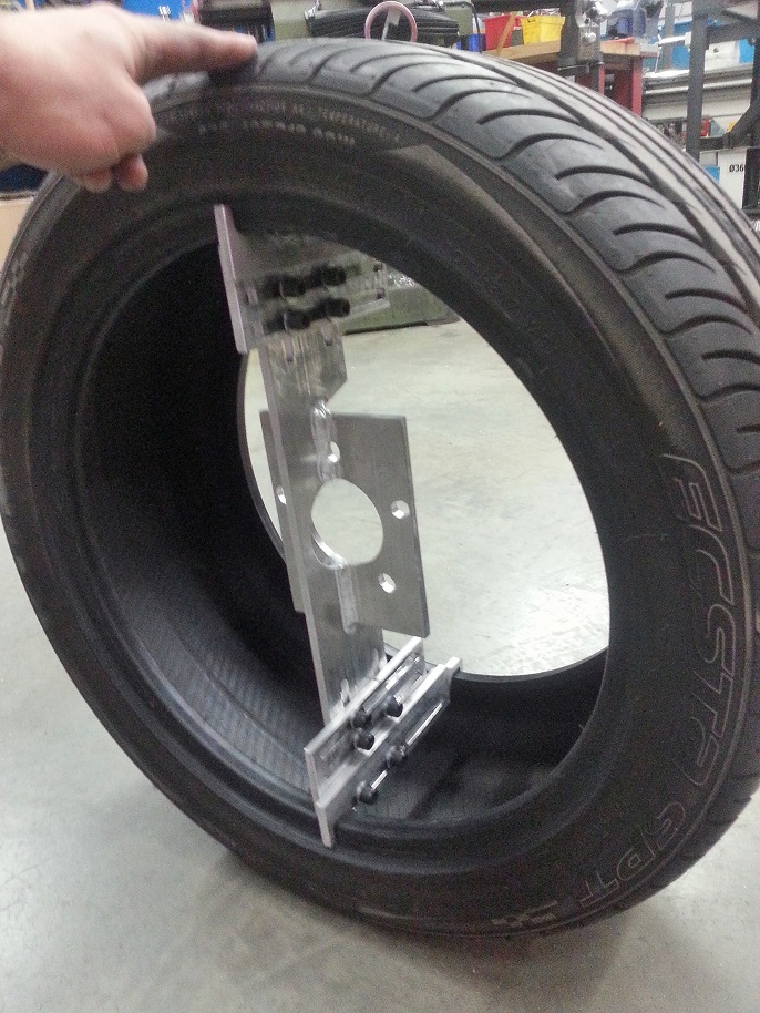
In lieu of dicking with electrically stuff, I've gone back to something I know I can do.. making stuff. I want to put the old rear 275's on the front, and the fact that the front fenders are about 1" skinnier than a 1st gen Camaro, and that widening rims costs good $$ (and I want to be exact), and also that I want to know exactly how much I'll need to notch my subframe.. I'm making a fake rim, AKA rim-mockup-tire-holding thingy. Gotta keep the audience entertained, so some pics from last night..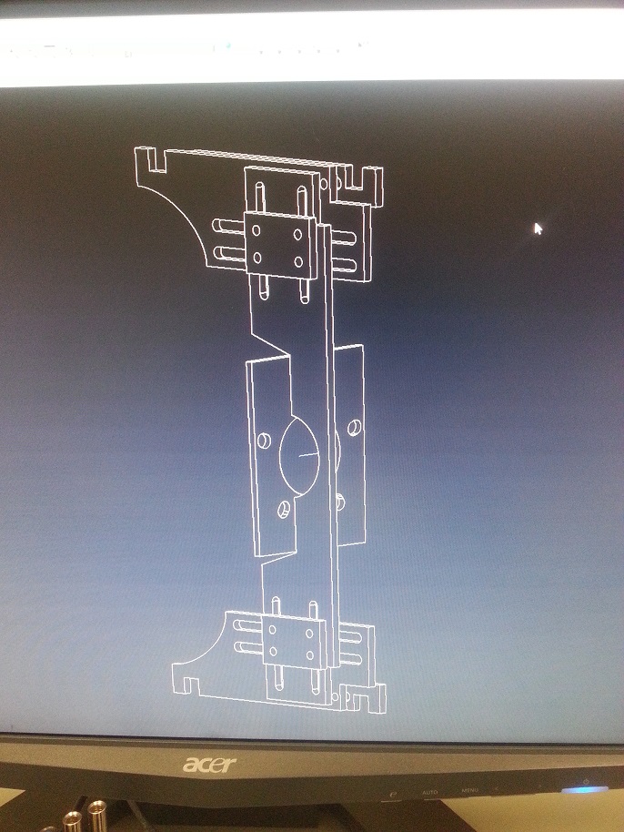
Hilariously oversized vernier calipers..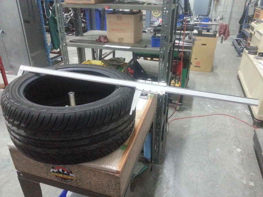
Mocking up the sidewall profile/stretch..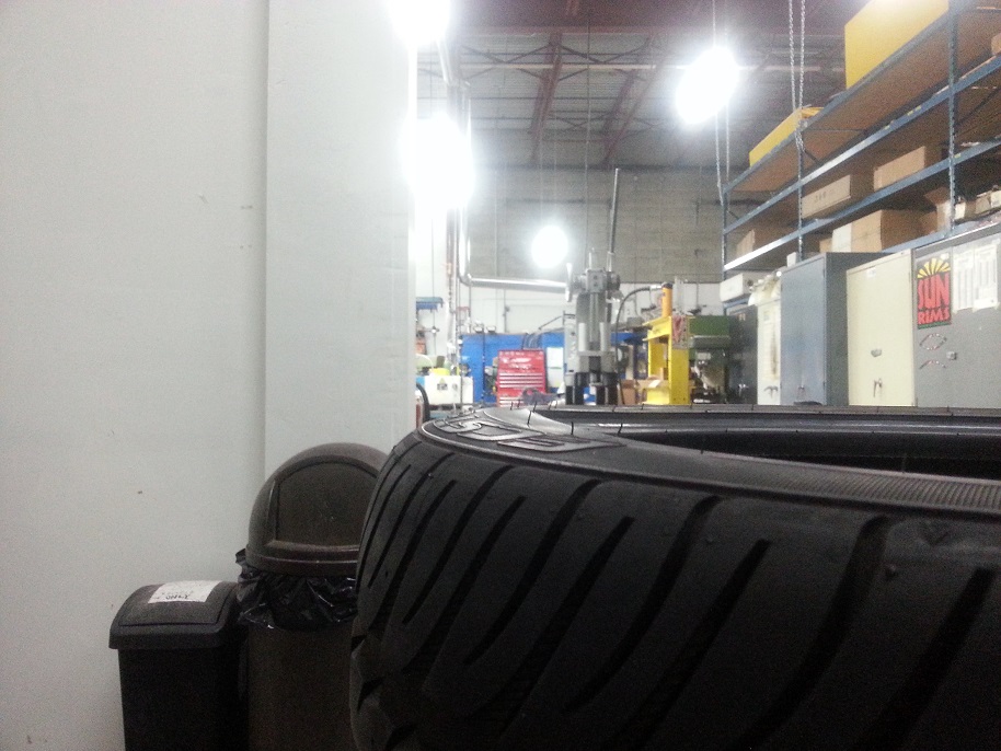
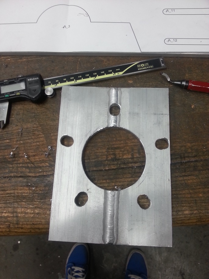
Getting a bit messy..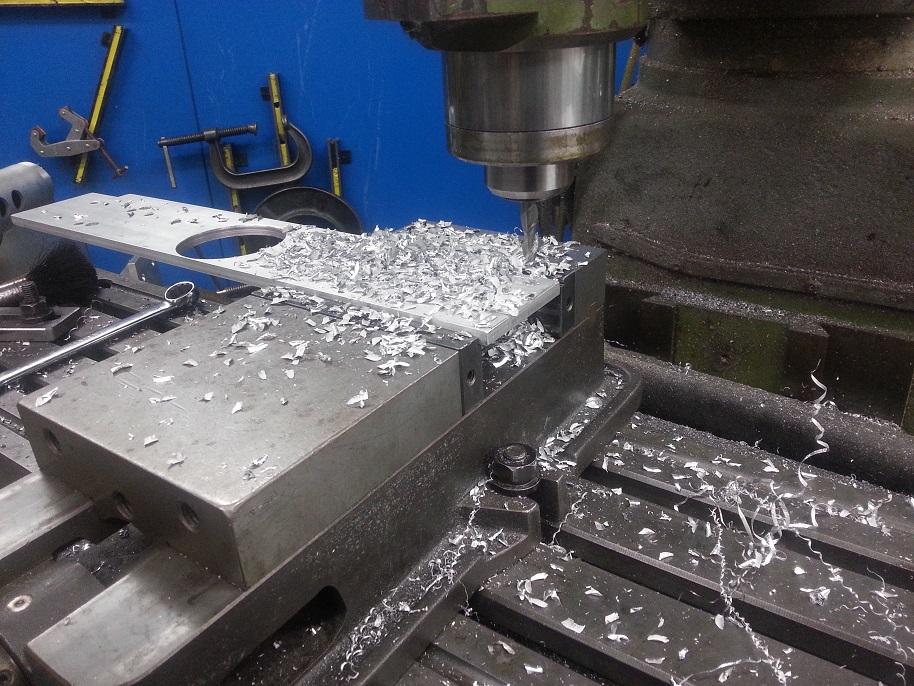
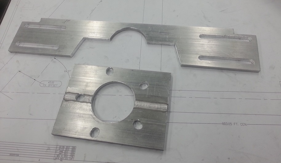
Even messier.. milling blind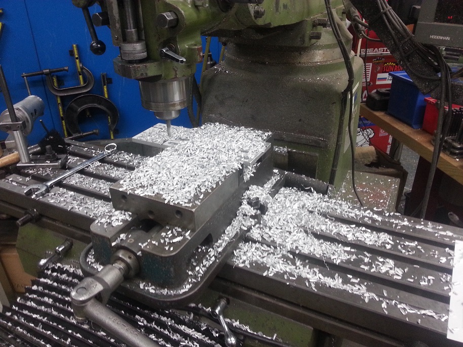
Just needs 4 weld beads on the longer upright to the center bolt-pattern-plate section, then some screws to bolt it together..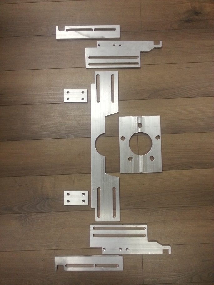
12-13-2013
Thanks! Welded the main two plates last night, and scrounged together some screws, so hope to assemble it on the tire when it becomes beer time later this afternoon!
As for the frame, it's a prototype that a colleague designed and we just started making. Before that we just finished making the prototypes of the frame I'm currently working on.
Just for the hell of it, this is the last frame I worked on that is now for sale for the 2014 model year..
Thanks! I'm happy with how that frame turned out.
I didn't post more of the motorbike cuz there were a couple complaints that this is my "car build thread"
In other news, the tire holder.. holds.. let the fun begin!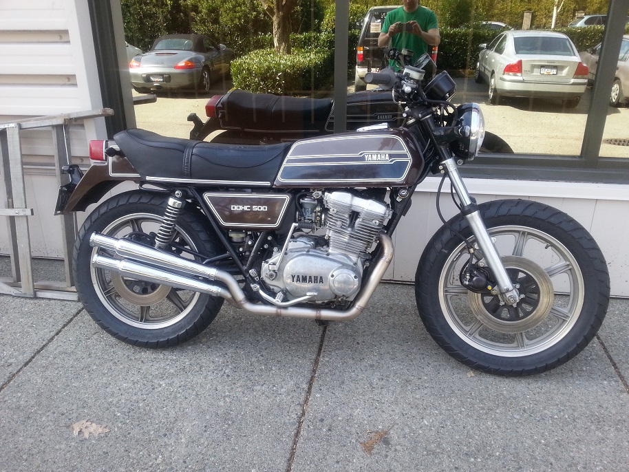
2-20-2014
2-25-2014
Maybe just alcoholic. That's functional enough to do other things as well..
I was actually laying most of it out like that to organize things, and happened to have the laptop booting up, so though "eh, why not make a nice little pic here."
Installing boost control and rough wiring tonight. Gotta make a ECU mounting plate, as well as clean up my gauge sensor wiring and figure my user-programmable Dominator I/O's. Going to tidy things up under the dash with those metripack connectors, as well as run VSS, fuel press, oil press, and maybe oil temp into the ECU so I can do neat computer calculation doohickies. This Holley program is quite impressive, so much versatility....
2-26-2014
Rifled thru the old "body harness" and gauge sensor wiring tonight.. what the hell was I thinking when I wired that **** 3 years ago. Funny how much work ethic & mental process paradigm can change in that amount of time. With the metripack connectors I'll be making a "ECU harness power connector" and "auxiliary I/O connectors" which will lead to a gauge-only sub harness for gauge sensors into ECU main harness, then a secondary plug for output from harness to gauges. Some wires will be a direct patchover from gauge sensor input to gauge output (coolant temp, boost, oil temp, fuel level), and some will input into the ECU for calculations, then be re-outputed to gauges (oil pressure, fuel pressure, speedo, wideband). This should create a clean point A-to-C [sensor to ECU), B-to-C (body power to ECU) and C-to-D (ECU to gauge panel) set of wiring. Damn age-old adage of "do it right the first time" is holding true.. if only I were this forward-thinking a couple years ago.
Sorry Mark, burnouts in front of your house will be delayed a bit longer, but at least that gives the snow time to melt..
3-8-2014
Well it's rainy as hell up here, which means for the first Friday in a while, I stay in and keep it low-key... wiring.
Since I'm at it doing a whole new wiring setup, the old cobbled-together wiring from 2.5 years ago (knowingly didn't care as much as I should've because I just wanted to drive it already) just cannot be tolerated anymore. Starting with dash, which will then work back to body-side wiring (essentially bat +12V, switchable 12V, and lights/signal indicators), and also branches back to gauges in/out from ECUand gauge sub-harness bundle.
So far I'm happy with the little clean-up progress I made, as well as the overall plan I have for it in my head.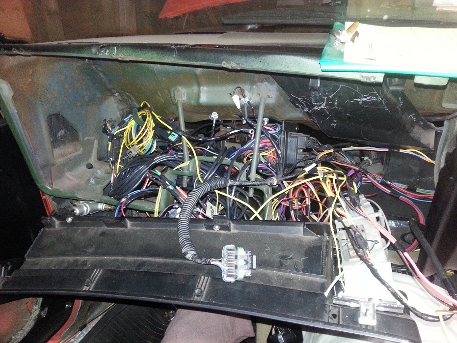
Also de-loomed the harness and started moving the sensor plugs to more appropriate loom-exit locations for nicer engine fit-up. Also moving the switchable/battery wires, ECU I/O, and fuseblocks further up the harness closer to the ECU, as they came exiting the loom practically in the engine bay.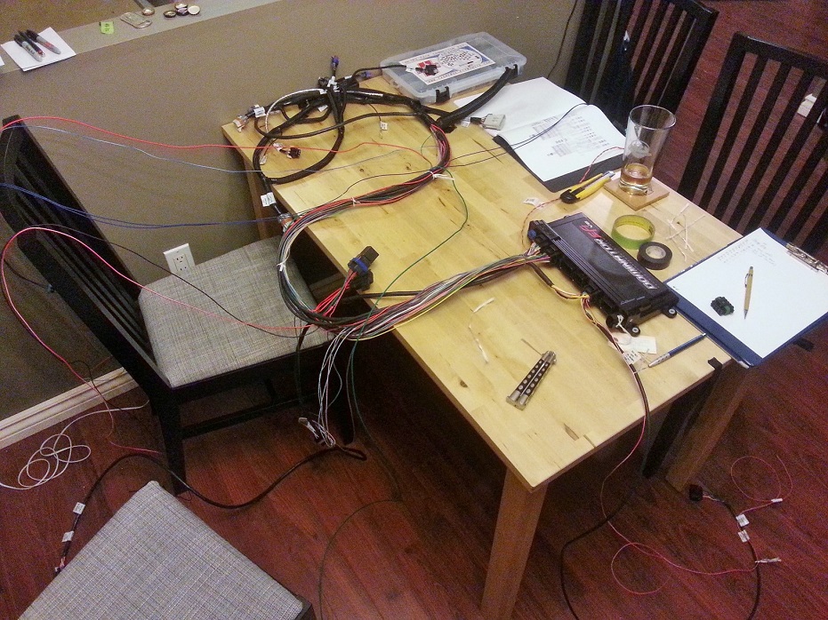
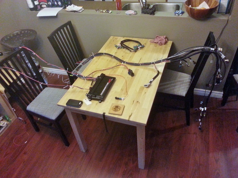
What a mess, this has gotta be dealt with..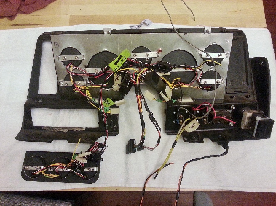
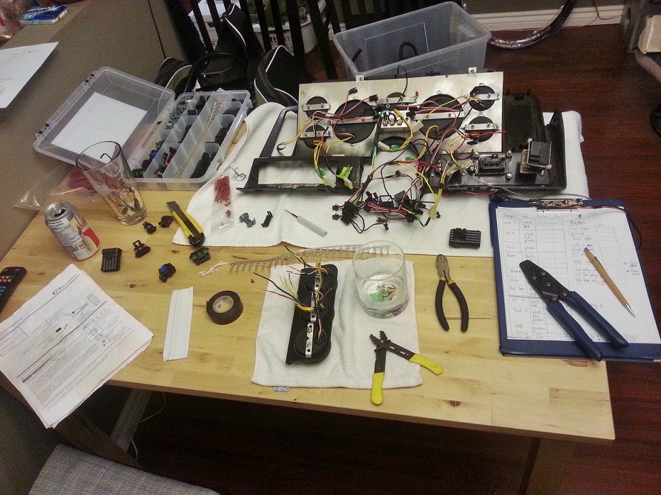
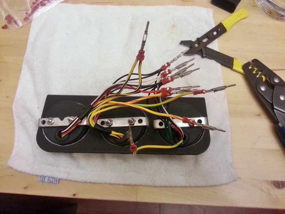
Ahhhh *sigh of relief*. This lower 3-pack of gauges has to be removable because the top lip of it covers two of the stock-plastic-dash install screws (3-pack bracket then screws into the plastic dash underside). A pleasant sign of things to come..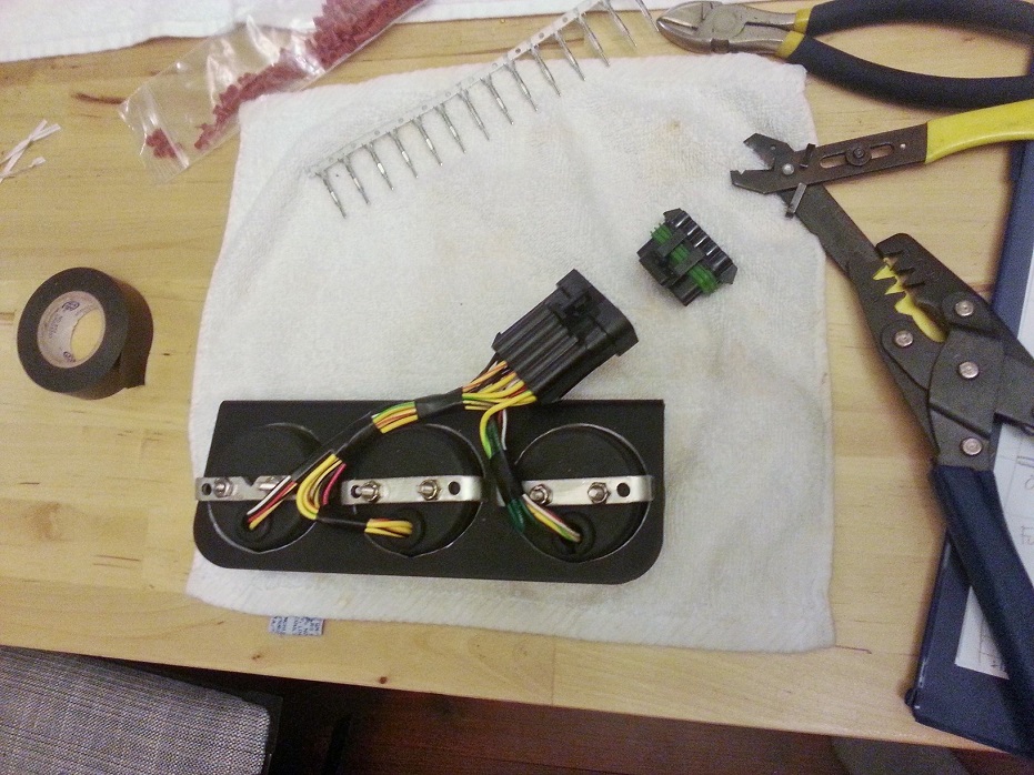
Getting there, left side complete. This is actually kindof fun seeing the neatness progress happen, even tho it's 3am...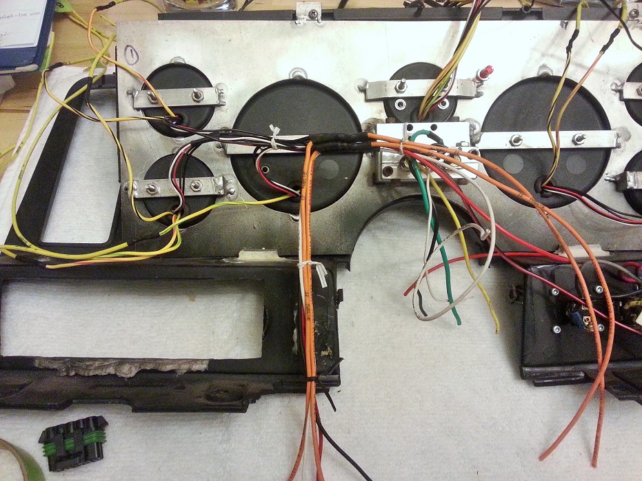
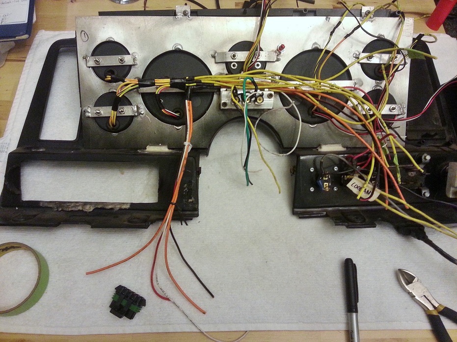
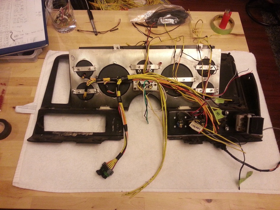
3-10-2014
Ohh yea, there we go. FYI.. beer does NOT help with this process. I would've liked to have one main plug, but I decided to separate it up to lights/power/ECU ouputs/gauge sensor outputs.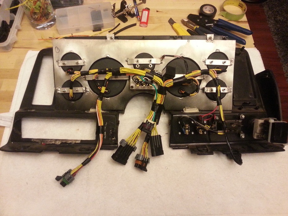
3-27-2014
Holley wiring harness is re-organized including connections to body & gauges, and the sensor sub-harness and body power/lights are all re-wired/plugged. Just waiting on my passport to go pick up a Holley boost sensor and several other "goodies" from across the border. Hoping to do that early next week. Once I connect the Holley wastegate dome pressure sensor, all wiring is ready to be dropped into car..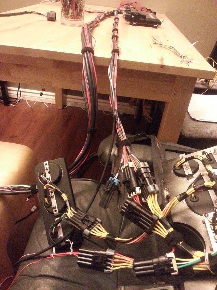
Thanks. I'd say I probably have about 15 hours into all the wiring. The majority of work was splicing/soldering/heatshrinking along with figuring out all the proper lengths for multiple wires going to the same plug.. and testing. The actual plug pin crimping was super easy and quick after learning on a couple test wires. It wasn't necessary to spend as much time on the Holley-harness side as I did, but I wanted to make sure each plug had the proper amount of length going to it from where I marked my "firewall-pass-thru location" to be, without there being excess length needing bundling that cluttered behind/under the manifold, firewall, etc.
The Holley electronic boost control system uses a MAP sensor (pre-tuned sensor values are programmed in for either a Holley branded one or a GM-part-number-specific one, or user-defined) so I'm re-using my GM 2.5bar MAP, but it also needs a compressor pressure value from before the TB, and I'm unsure of my Speedhut boost gauge sensor enough that I don't want to fiddle with user-defined values/offsets in the Holley program, especially for finely-controlled boost. The Holley sensor will connect to the pressure-reference-signal side of the wastegate (wrote BOV before for some stupid reason, obviously that was wrong) aka the "dome".. which is just the top.
It's awesome how flexible the Holley system is. Any free ECU-side pin (AKA isn't dedicated to main harness function) is tunable. You just highlight the pin # on the computer program and select from the following:
Inputs:
- 'hi' +12V trigger signal (4.5V-24V range)
- 'lo' ground trigger input
- 0-20V sensor input
- 0-5V sensor input
- specific thermocouple input (select pre-tuned values from dropdown menu)
- frequency input (select pre-tuned values for usage, including VSS)
Outputs:
- 'high' power switchable +12V
- 'lo' power switchable ground
- PWM +12V
- PWM ground
Once you physically connect a pin, you look at the pinout map in the program, and you drag and drop "pre programmed" signal input/output functions (dome pressure sensor signal, VSS, etc) onto the pin # on, and it's programmed!
4-5-2014
4-6-2014
In the end it did add up to a bit more than I was hoping, but oh well. $1500 for Dominator ECU, $300 for the main harness, $100 for injector sub harness, $100 for DBW sub harness, $100 for Holley-specific WB sensor, $100 for boost solenoid, $100 for boost sensor. I could've fiddled and pinned in my existing Innovate standalone WB controller, and fiddled/coded my Speedhut boost sensor to work with the ECU to save some money, but in the end I decided I didn't want to introduce potential errors with custom settings for WB and boost control, and potentially compromise the precision of the system for the sake of saving $200, since the whole reason I shelled out all this cash for a new setup was for a pre-configured "happy" whole system.
4-24-2014
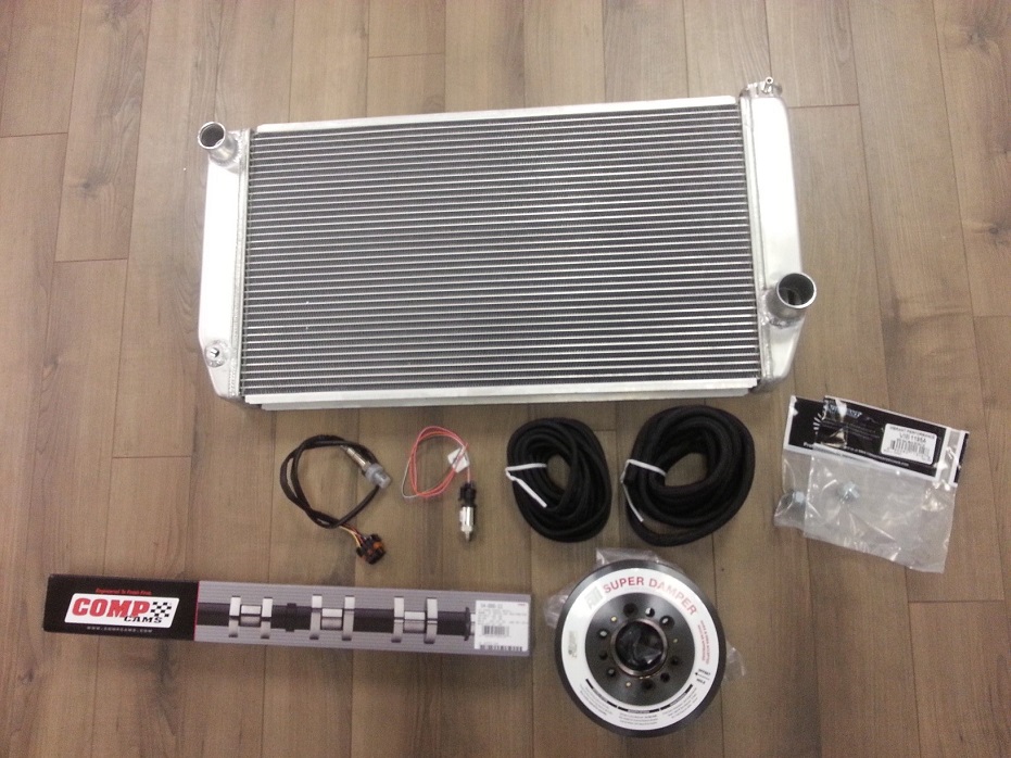
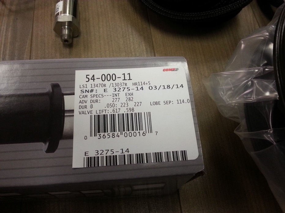
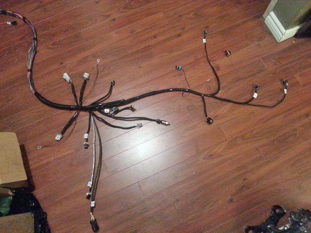
Made it to Asia and back without pulling a 370, so wrapped up (literally) the harness tonight. If I have enough energy tomorrow night might go and install it so I can mock up Holley ECU holding bracket. Either way I'll be in the garage on Saturday doing the cam swap and rad install.
Happy to have all the plugs at their neat & proper minimum required lengths and branch locations. Other than running out of big-diameter loom, almost looks like it came this way..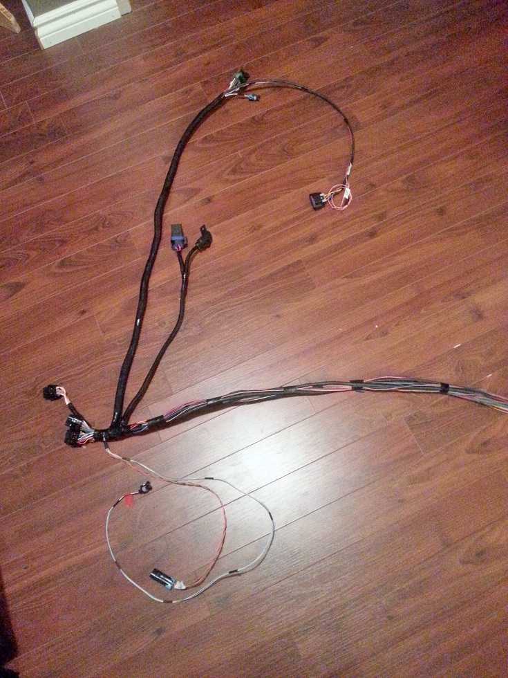
4-27-2014
Haha, funny guys. I'm definitely running out of projects, that's for sure.
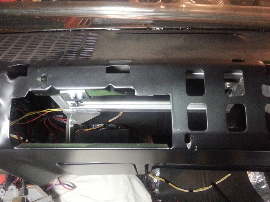
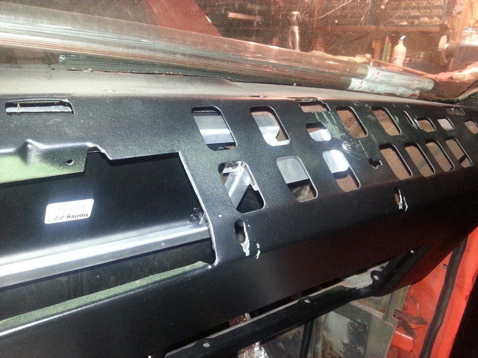
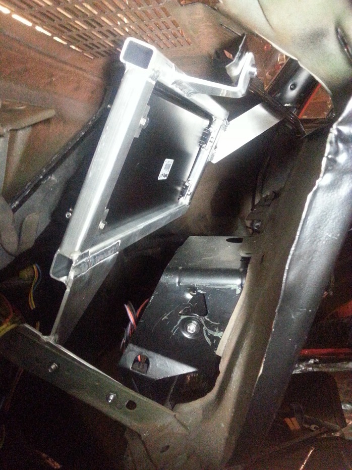
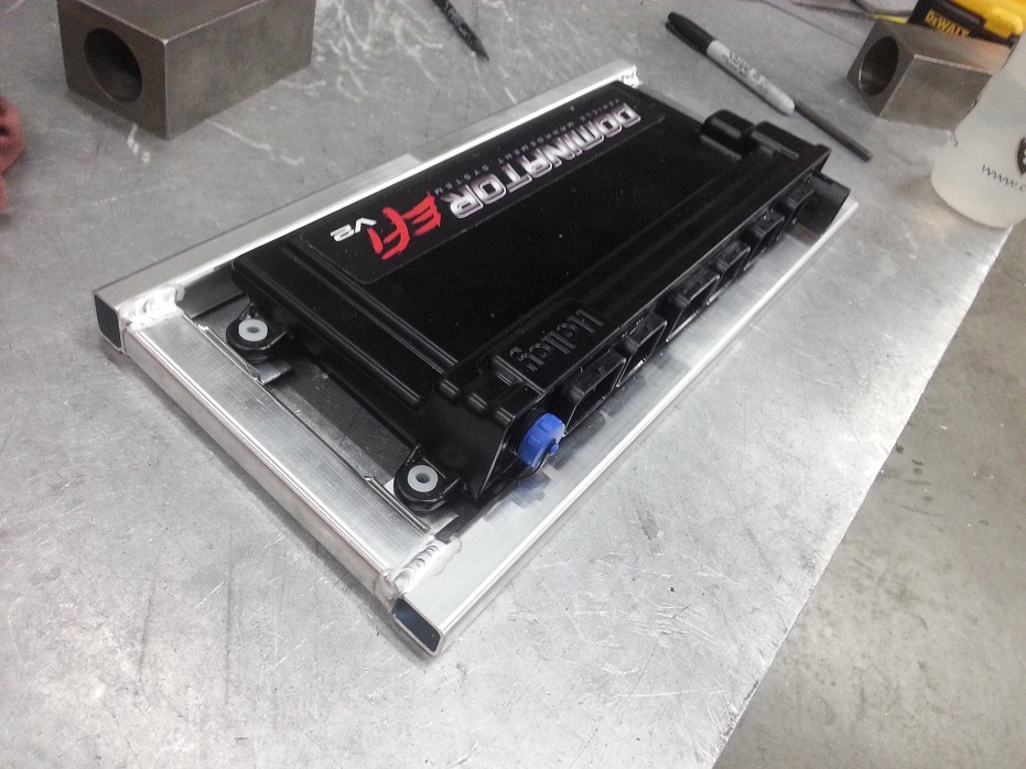
Started the ECU bracket yesterday, going to mock it up in the car today to figure out how to orient the to-body support struts. It'll be mounted vertically, with plugs pointing down, between the heaterbox and the glovebox. This ECU is massive.. gotta be about 13" long and a good 7 or 8 lbs.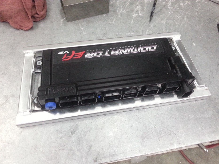
4-28-2014
The supporting bracket isn't too crazy.. 3/4" rectangular alu tube with 0.065" wall.. very light. The overall size of the ECU is likely due to all the extra auxiliary plugs, and their required circuit board(s), which requires bigger alu case, which requires more filling, etc.. slippery slope. It's slim so it'll tuck nicely the way I want it to.. trick will be getting the angles of supporting struts right to re-use some existing holes under the dash.
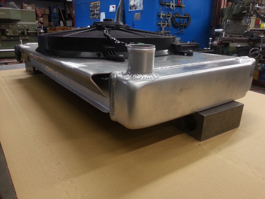
I knew my current/old rad was on the small side, but forgot how much so.. quite surprising it was even able to keep this thing cool at all..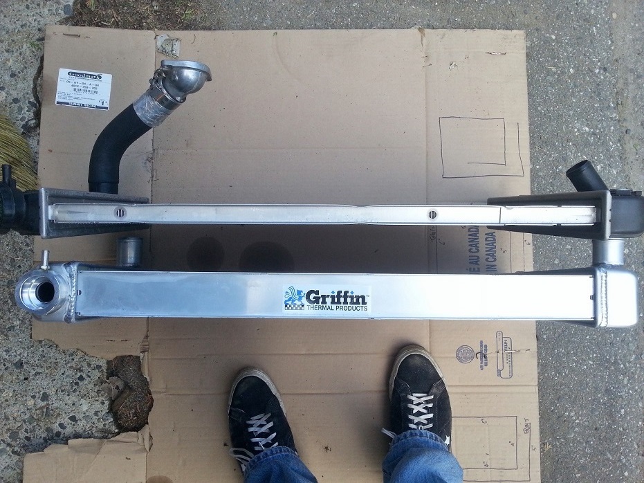
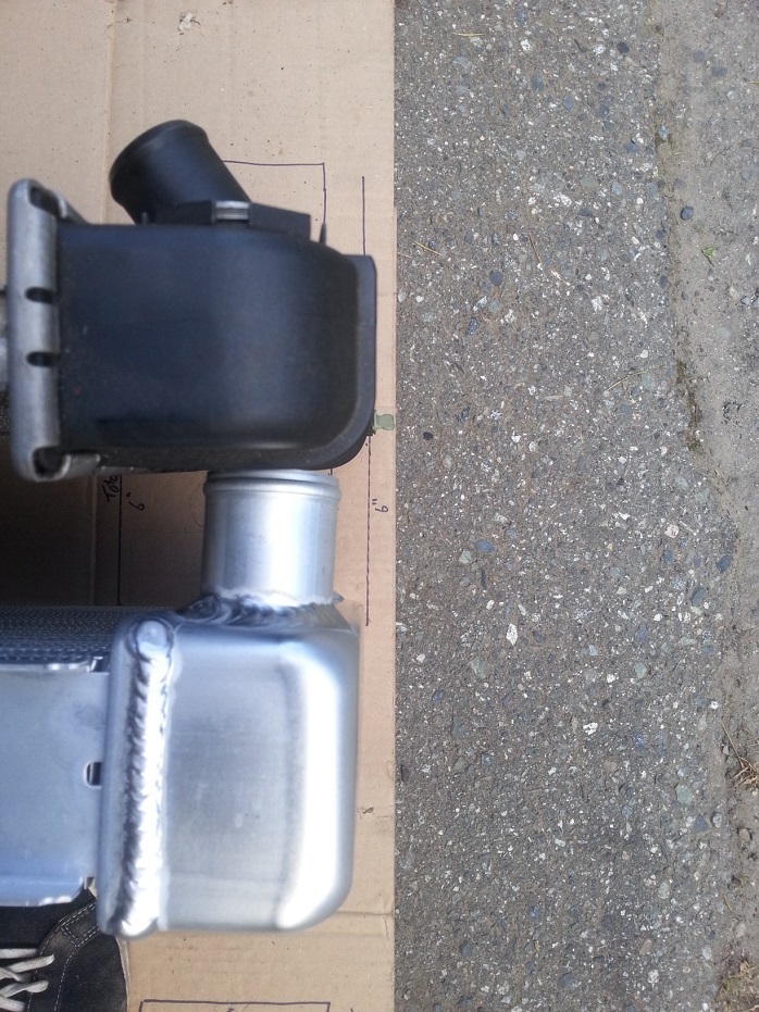
The Griffin rad has a higher top left outlet and lower bottom inlet, so if the old setup was in a "neutral position", I'm going to have to shift the new rad down so that the top left outlet still tucks under my intercooler ->throttlebody charge pipe, but not so low that the hose to the bottom left inlet is at a crazy angle, or that my large single (14" I think?) fan hits my turbo hot side cross-over pipe. Will be a lot of trial test fitting. Dual 10" fans might be the easiest way to go so I can slam the rad down low and not worry about the edge of a large single fan's shroud coming close to or hitting the heat shield on my turbo cross-over pipe. Also I'll have to angle cut/weld the top left outlet to better redirect it. Arg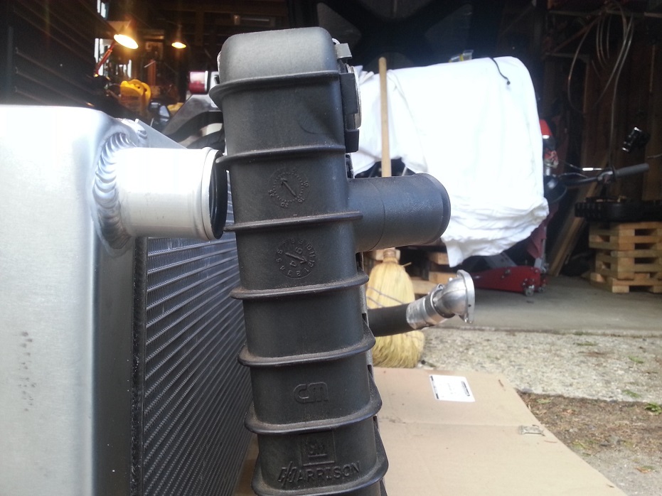
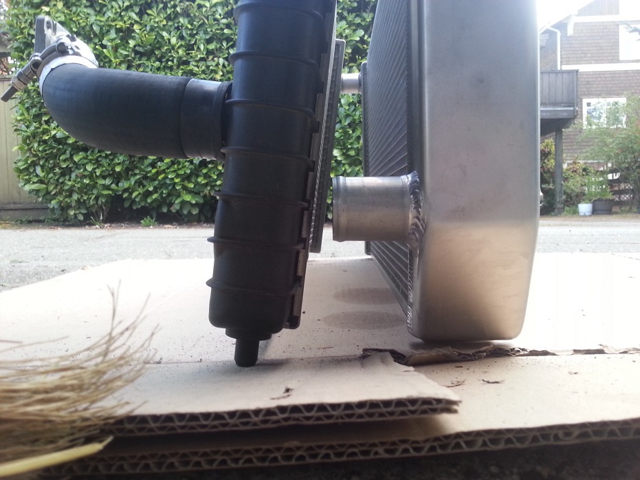
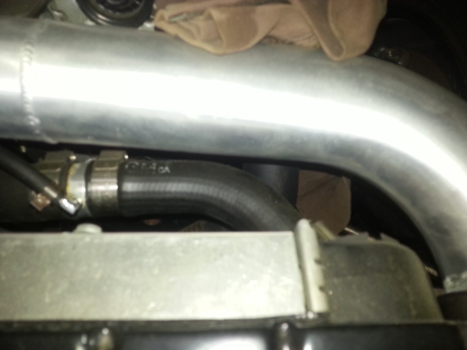
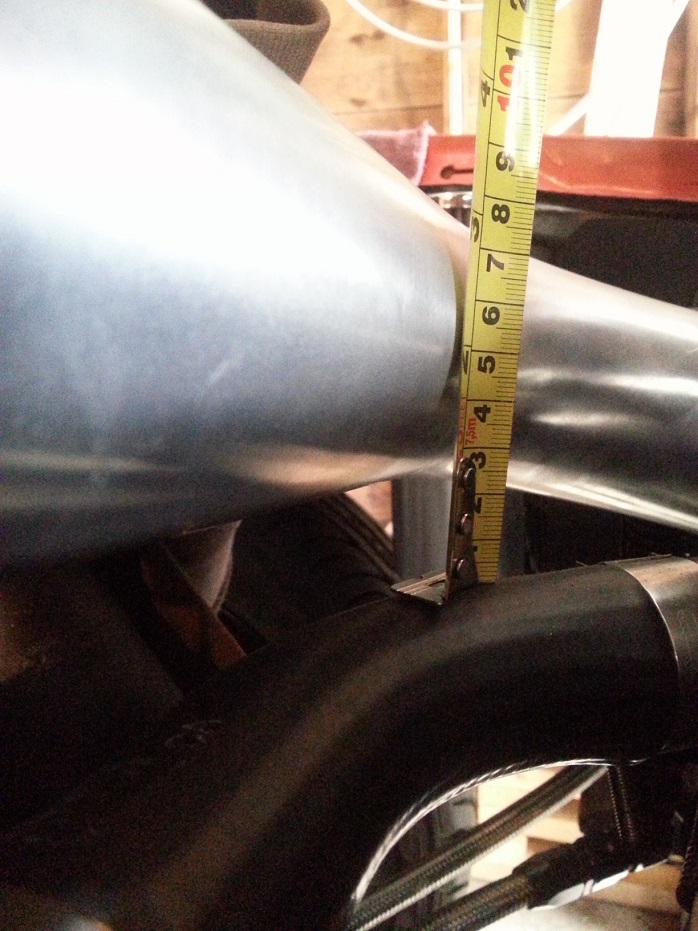
5-1-2014
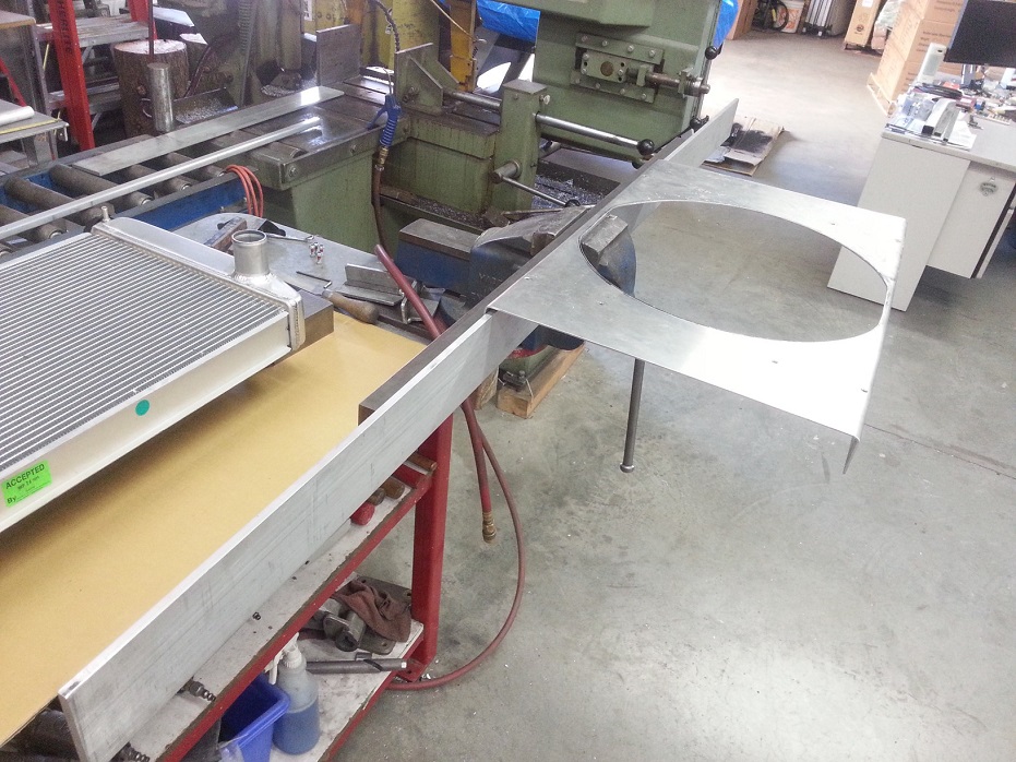
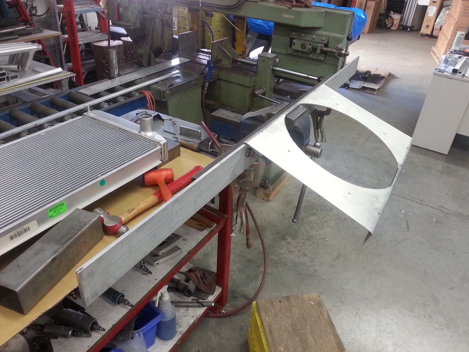
Got the old radiator shroud bent up and re-purposed to fit on the new rad. Still have to weld close-out plates for the exposed upper corners of the shroud, and figure out where the new radiator-coresupport brackets will be before I weld tabs onto the radiator to mount the shroud to.
In other news, this is ridiculous cool...
5-4-2014
Prettymuch all the crap had to come off for this cam swap, oh well, it'll be worth it.
Just about to pull out old cam..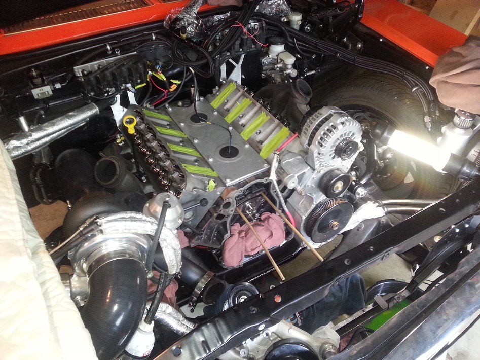
Beautiful little piece of turned automotive jewelry. It's going to make such glorious sounds..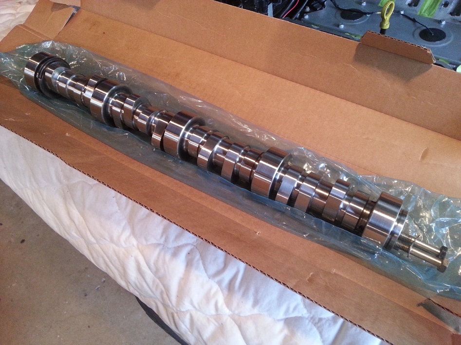
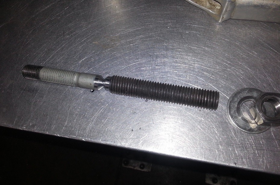
New cam all lubed up and going in. I got as far as cam gear cover loosely tightened on, but the new ATI damper has less of an initial counterbore step on the hub ID, as well as a claimed tighter pressfit, so I couldn't get it to initially slide on enough for the stock GM crank bolt to engage the crank threads. Going to cut the stock bolt and weld on some 3/4" rod to turn it into an installer stud, then a new bolt for final torque. Even though this northern wintery land of Canadia is all metric and stuff, I haven't the faintest idea where to look for 16mm threaded rod, so I'll just modify what I have to work.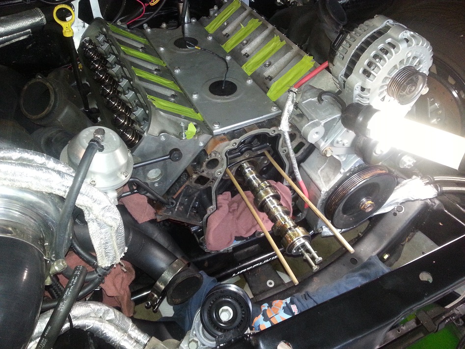
5-5-2014
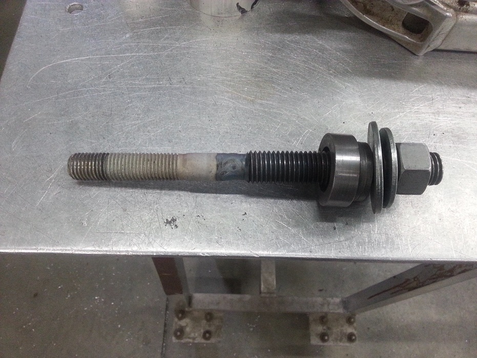
Made the ATI damper installation tool made, just welded on some standard 3/4" threaded rod.. I think I used half a filler rod just for this one weld, haha. Now I just have to go to the friggin stealership to get a new crank bolt.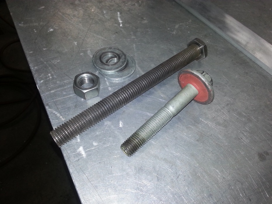
Also made a bit more progress on mounting this behemoth of an ECU. When I stalled out on the installation of the ATI damper I mocked up the ECU in its final tucked position under the dash. It's so heavy it's hard to take a pic just holding it there, but if these tack-welded brackets transferred over ok from my cardboard templates, then this should be final-welded and ECU bolted into the car this week.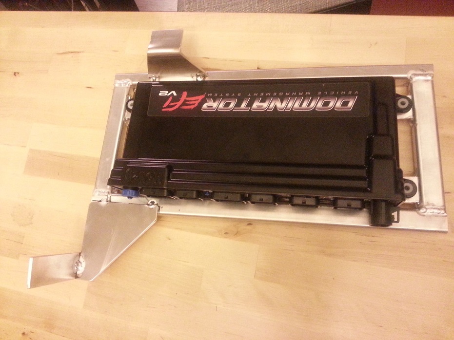
6-1-2014
Added a 3rd brace point (to the sheetmetal hidden underneath the dash pad) for the ECU and got it mounted.. it's in a similar location as old GM one, but more accessible (shifted more to passenger side) and there is still room to fab/install a glovebox.. at a later date.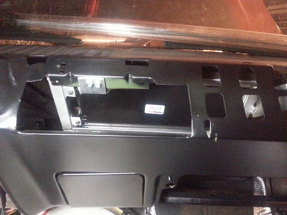
Finished modifications to the old fan shroud, including a clean-up air powered Scotchbrite belting..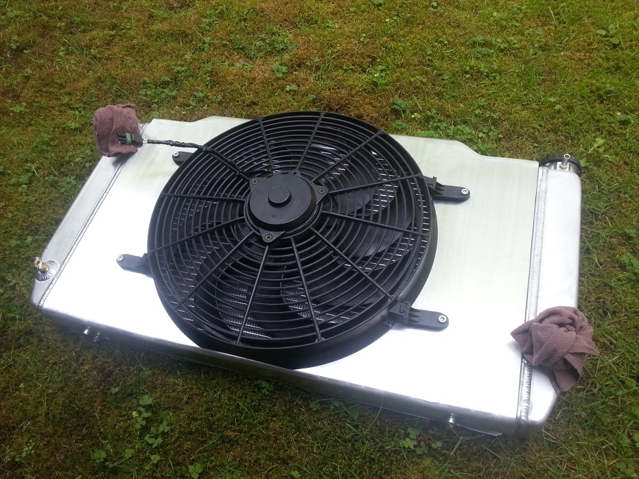
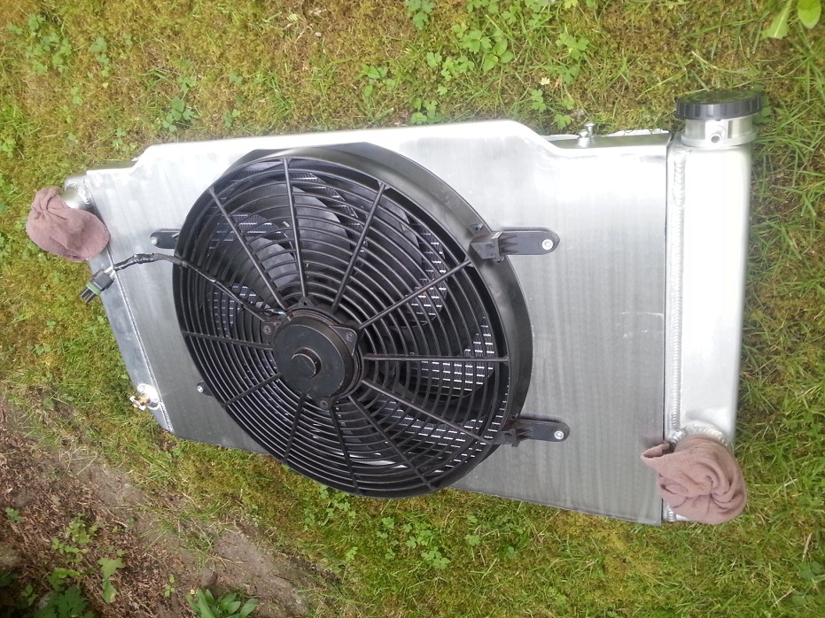
These next pics show the 3D contouring of the top corners, partially to look neat kindof like a molded plastic shroud, but mainly to turn the downward-angled top bend into a flat surface I could use to mount the shroud to the rad..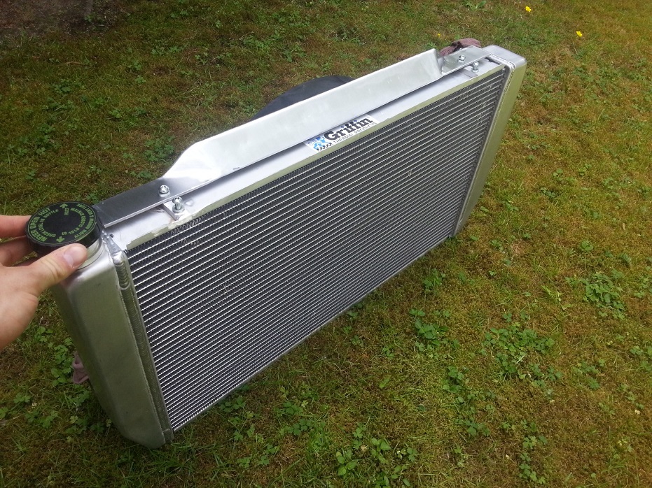
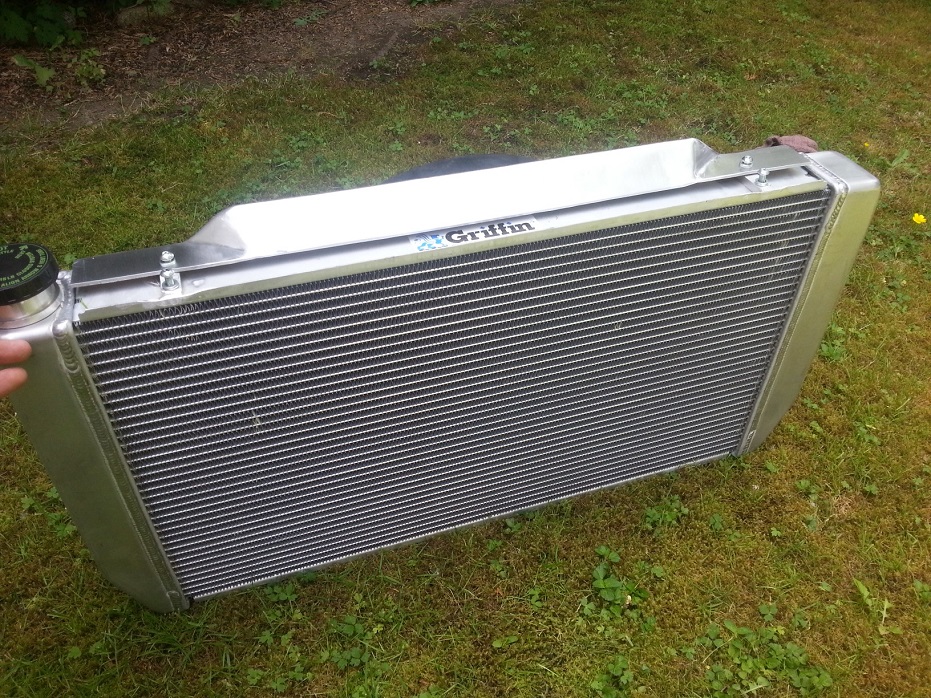
I cut/tapped/welded 4 strips of 3/8" aluminum to the top and bottom channels on the rad, so that the rear 4 sets of threaded holes mount the shroud, and the front set are what the frameside brackets secure to..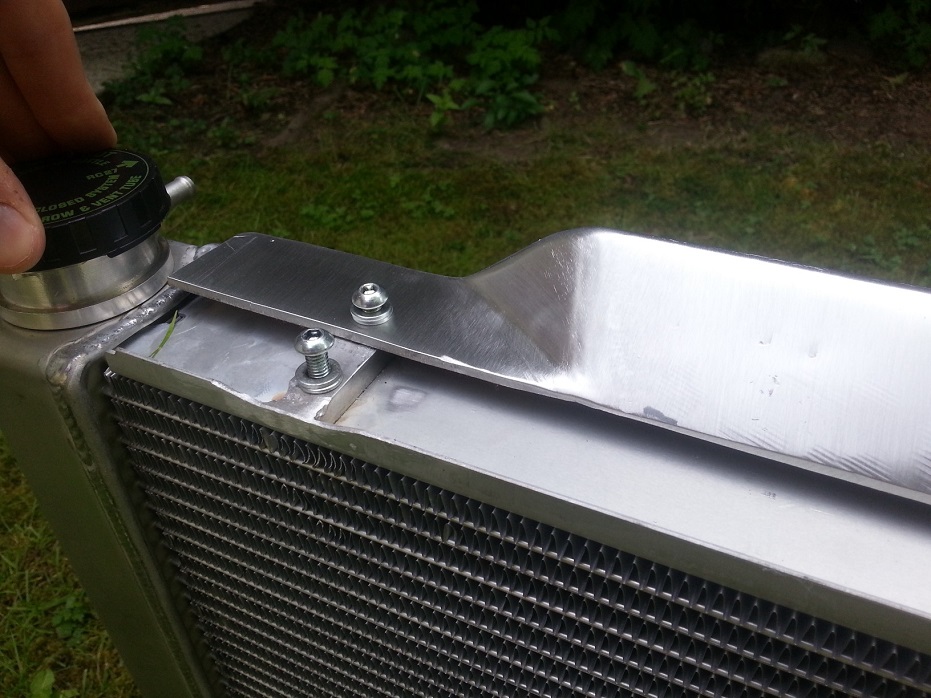
Cutting off the old rad brackets, grinding, sanding, and welding new brackets on. I HATE having to do this dirty metal work on the car, much prefer creating a mess in the shop on a bench. So I tried to make it as sanitary as possible. Kindof looks like a patient having heart surgery, haha..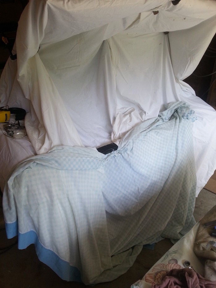
Rad being mocked up. After these pics I welded in bolt-on strips to the rad support, but I still need to make some aluminum L-brackets to connect the rad and the rad support.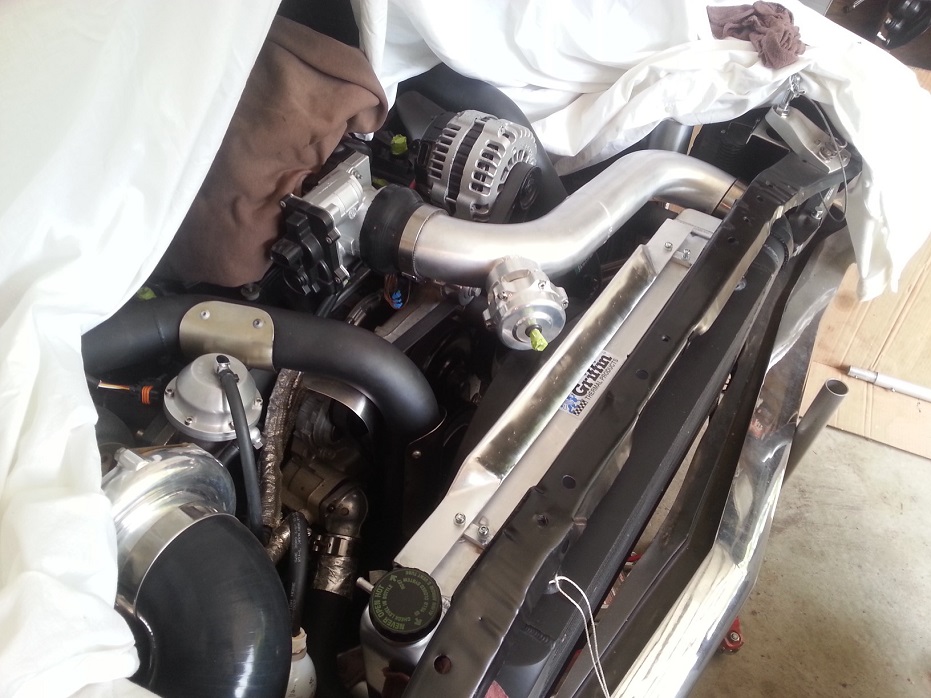
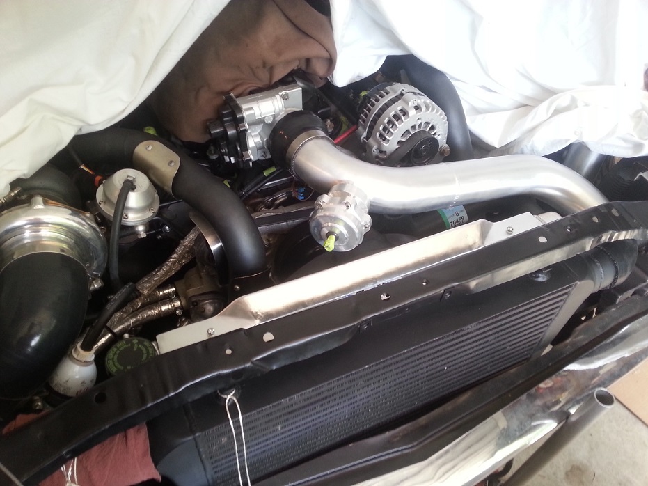
I really hate how short-nosed the Nova is. I thought the old rad/fan setup was tight to the hotside pipes, but shoe-horning this new setup definitely needed some bending & black magic.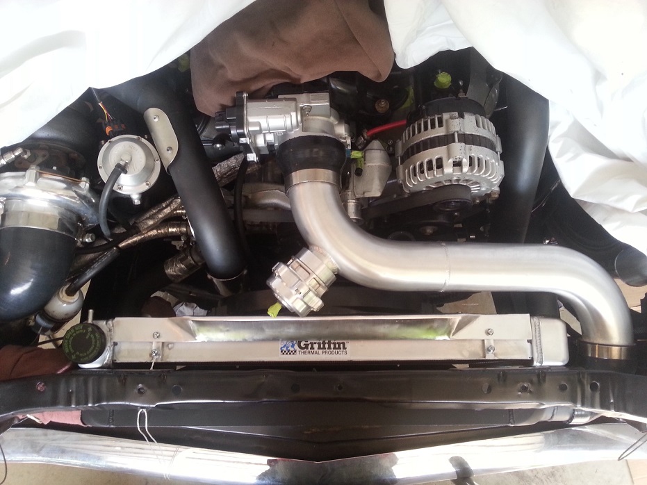
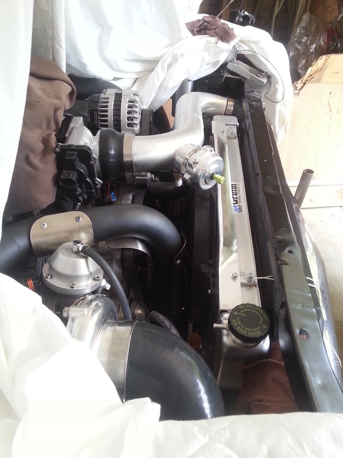
This rad hose info might not be applicable to many of you, since I made a connecting tee for my upper hose to tee in the vent line, and that allowed me to only have to worry about each 90* end section individually, and I could fab the tee however I needed, but I'll still throw this up here with part numbers.
The LS waterpump upper outlet is somewhere in the neighborhood of 1.25-1.375" OD I think, but my new Griffin rad needed a 1.5" upper hose and whatever size I had wouldn't stretch, so here's what I found.
This is a neat s-bend, both ends are 1.5" ID, one end is just under 90* natural bend, the other end is just over 90* natural bend. Dayco part number 72112..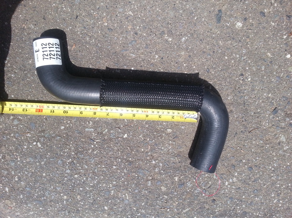
I also picked up this hose, which is the one I ended up using. The two bends are in different planes, but both ends are 1.5" ID, and the nice thing is both ends have different radii of bends. I ended up using the right end with a gentler bend for nice flow, and because I could afford the space, but in a super-tight engine swap case, the left side with the super tight bend might be the ticket. Dayco part number 70469..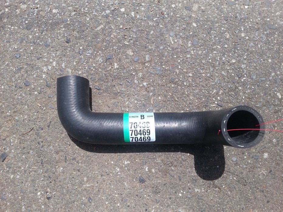
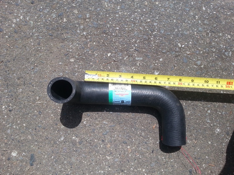
This lower rad hose is the money-maker easy button one that could probably help a lot of people, or at least short-nosed Nova people with a Griffin or other rad that has a larger-than-stock outlet diameter. Stock LS waterpump lower inlet is 1.5" OD I believe, and my Griffin has a 1.75" lower outlet. This hose was prettymuch a perfect fit. Dayco part number 72183..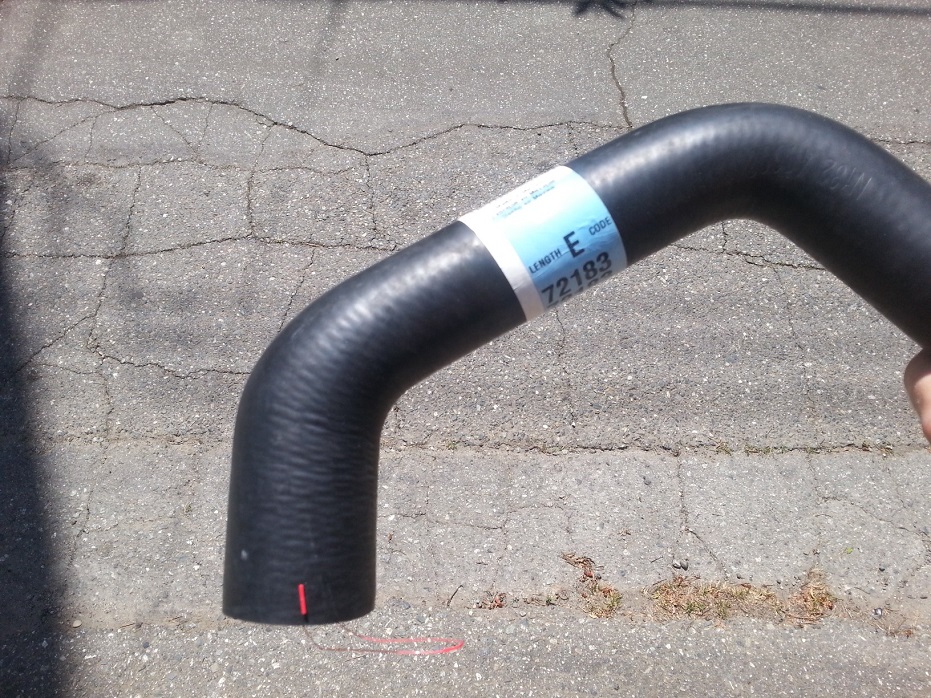
Old 1.5"-1.5" hose vs new 1.75"-1.5" hose..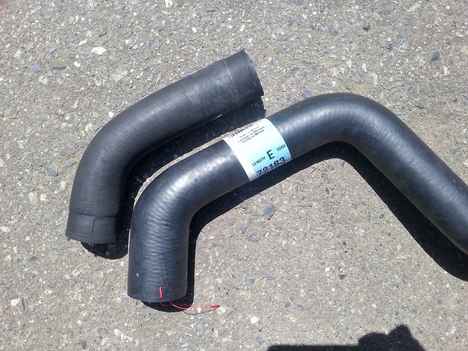
Ohh yeeaa..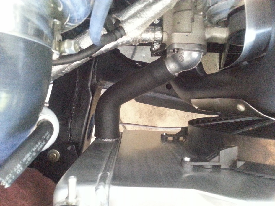
7-14-2014
My rad shroud is ~ 1/2"-5/8" off the rad core, and shroud can't move back more due to turbo crossover piping, and rad can't move forward more due to intercooler, which can't move due to grill(already clearance trimmed) and bumper. Also, open area of rad has improved since previous rad setup, but half the area is still blocked by the intercooler, so I'll be relying on the fan 90% for cooling abilities.
Been struggling with throttle error codes on the Holley setup, but I discovered you can tap into and display every sensor input, so after swapping out a seemingly-bad old throttlebody (variable resistance on TPS #2 was ok, but the variable voltage was dead.. likely tha the input +5V connection to potentiometer got fried), and swapping some wires, I got the codes to go away.
In the Holley software there are neat drop-down selections for what throttlebody calibration to use (5 or 6 popular GM/Ford/Nissan throttlebodies), and so you'd think that as say the TB was changed from an LS2 to LS1 type (6pin vs 8 pin, same-direction-TPS-1-and-2-sweep vs inverted-sweep) then the ECU-internal wiring logic would recognize and compute accordingly.. nope. First I had to hardware splice an extra set of +5V/ref low wires from the 6pin LS2-TB-intended harness to a new 8pin plug for my old 8pin truck TB. Then I had to swap the "conventional" direction of the TPS #2 polarity because for the truck TB, the TPS#2 sweeps in the opposite direction of TPS#1. It was throwing codes with the plug previously wired "correctly" even when the tune was programmed for either type of TB and thus TPS-sweep-direction. Another thing, the error codes "error(5)", "error(8)", "error(9)" are assigned completely arbitrarily accoridng to a Holley electrical engineer, thru the Holley tech help guy.. and the codes have absolutely no meaning for reference/troubleshooting.. hmm.
Anyways. Got the codes fixed, all sensors check out, except for now the ECU is only recognizing the pedal travel up to 10%, then deadheads for the rest of the pedal travel, even tho the APP (AccelerationPedal Position) voltages increase accordingly to WOT. Another call to Holley tomorrow.. dammit...
7-16-2014
So re-wired my brake pedal switch, and managed to get both APP sensors in the pedal to recognize full pedal sweep (0% pedal -> 100% pedal is: 0.96V -> 4.3V for APP#1, and 0.48V -> 2.14V for APP#2).
At the same time, now that the ECU doesn't think I'm trying to mash the pedal while brake is applied (anti-brakestand programming, much?), the TB position sensor reads 0% -> 100% with TPS#1 reading 1.2V -> 4.32V, and TPS#2 reading 3.88V -> 0.74V.
Time for another call to Holley.. so damn close!!
Pedal @ 0% (closed):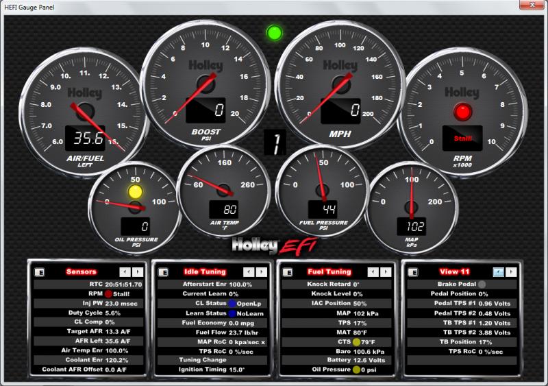
Pedal @ 100% (WOT):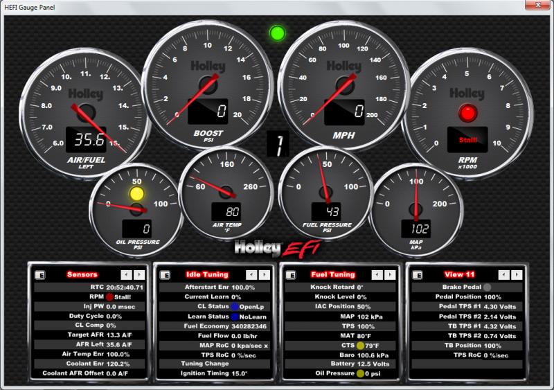
Pedal @ 0% while cranking: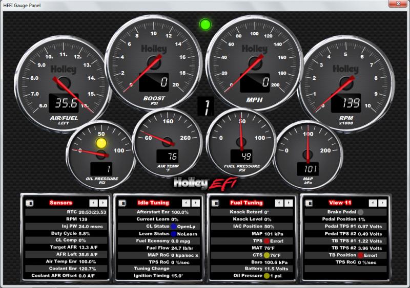
8-6-2014
Holley ecu/harness/pedal/throttlebody are on their way back to Holley. My tune seems good, my pedal is good, my throttlebody tests good for variable resistance & variable voltage on both TPS's, but for some reason upon cranking the signal voltage on TPS#2 jumps higher than its fully-closed voltage, and Holley can't figure it out from my data logs. I've wired the TB plug in numerous test ways to create same-direction TPS voltage sweeps, inverse direction the proper way as well as swapped, and probed all grounds, 5V refs, signal voltages, and reference voltage drops, and everything seems to check out when the key is just in RUN, as well as checked cranking 12V continuity. Arg!
Warning: this post is NOT CAR RELATED.
Ok, while I've waiting for back-and-forth communications with Holley, got my bike back on the road. Since it was running last summer I replaced the broken shift-lever-return spring, cleaned/brushed the sidecovers, put a smaller headlight on it, and also a **** ton of modifications to fit a 2005 R1 4pot caliper on the front. The caliper backside hit the spokes, so.. spacer to move the rotor out from the spokes -> spacers to space the fork legs -> upper/lower crowns chopped/plated/welded wider for the widened fork leg spacing, and a custom bracket for the caliper too.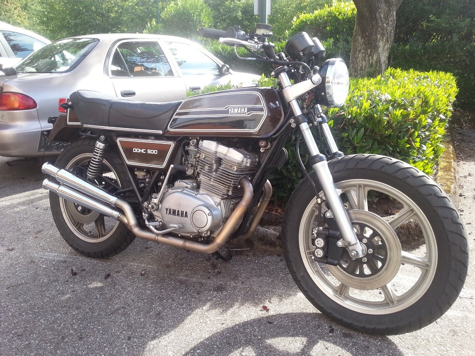
8-18-2014
So the harness/ECU/pedal/throttlebody have all been sent back to Holley. From what we can figure, the problem has been singled down to TPS#2 in the throttlebody getting an "over-voltage" upon cranking. As in when the TB cycles from closed to open from the pedal input, it goes ~4.5V closed to ~0.75V WOT, but when the TB moves during cranking the TPS spikes to 4.8V, so the ECU thinks the TB is closed even further past 0% throttle.
Holley has been very good with communication, deciphering my tune/logs, and even exporting me the raw data files for whichever sensors I ask for, so I can plot various relationships in Excel. Hoping they can figure out the issue when they bench test it on their engine, as well as swapping out known-good parts that they have.
In other news, I went and bought an entire interior for the car, so that's something to do while Holley figures it out for me.
9-12-2014
I've been talking back and forth with them, turns out that my truck TB operates differently than all the more modern TB's they have the system calibrated for, as well as my TB part number being erroneously included in the drop-down menu of "approved TB calibrations" even tho there isn't a specifically different calibration for the voltage and sweep directions.. so it was a number of factors adding up to it not passing internal safety checks and calculations. They said they got it running after changing a couple things but I haven't heard on when they plan to ship it back to me.. hopefully soon. I was emailing an electrical engineer directly for the better part of a week.. so it was cool to be getting legit technical answers since I'm also a more technical person.
10-13-2014
Just in time for monsoon season to start.
Lowered the target idle speed to 850 and corrected the target AFR.. that lope!!


10-16-2014
To put full plates on it it needs an emissions inspection.. a program which is disappearing come Jan 1, 2015.. so thinking save myself the hassle of day permit, then inspection (still have to pay for), then back to insurance office, just to have plates on it until Dec 31.. I'm on the fence whether I care enough. It kinda rains a lot up here in the PNW.
11-24-2014
I drove the car hard for a handful of days and at some point the oil pressure dropped enough to cause a bit of damage, however I never noticed it dip below 25psi at idle (I knew that was uncomfortably low anyways).
I was wondering what was up with the rattling, occasional metallic banging, very brief poof of smoke, and lack of boost on the last day I drove it. I figure this may all have started with my extreme low oil pressure from the screwed mains way back before I rebuilt the engine, and under varying loads, boosts, temperature, and accel/decel spooling cycles it just destroyed the turbo journal bearing.
12-28-2014
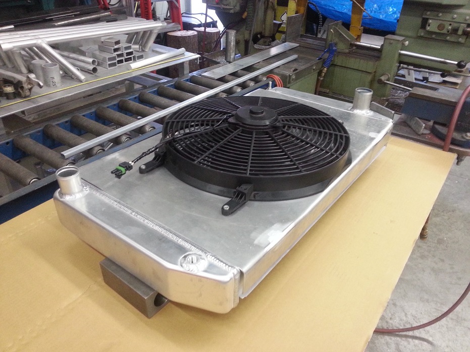
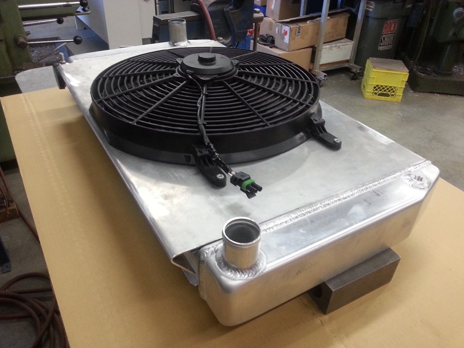
Couple updates.. regarding the "upgrade" to the 2.25"-thick-core Griffin rad, the single 2700cfm 16" fan simply didn't have the pulling power to pull air thru the 3" intercooler in front of it, then also thru the rad and have enough velocity thru the rad fins to cool the coolant (not cooling below 230*F on even on highway-speed pulls). Also, with where my hotside pipe from the passenger side exhaustmanifold looped forward and down in front of the waterpump, there wasn't enough room to locate a 2nd fan, as the fan motor would interfere with the hotside pipe.
I had to resort back to the previous thinner rad and run dual 1750cfm fans.. which seems to keep the engine running consistently cool at ~185-190*F after boosty pulls to quick stops on the street. Idling it was holding about 175*F.
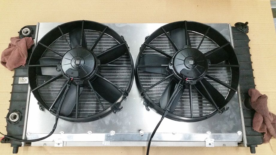
To get maximum clearance of passenger side fan to the hotside pipe, I reverse mounted the fan from the inside of the shroud, and clearance cut out the plastic ring between the mounting tabs, to allow airflow between the mounting tabs. The pictures will make it make more sense..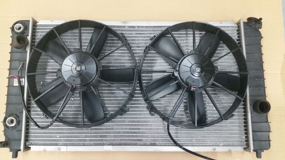
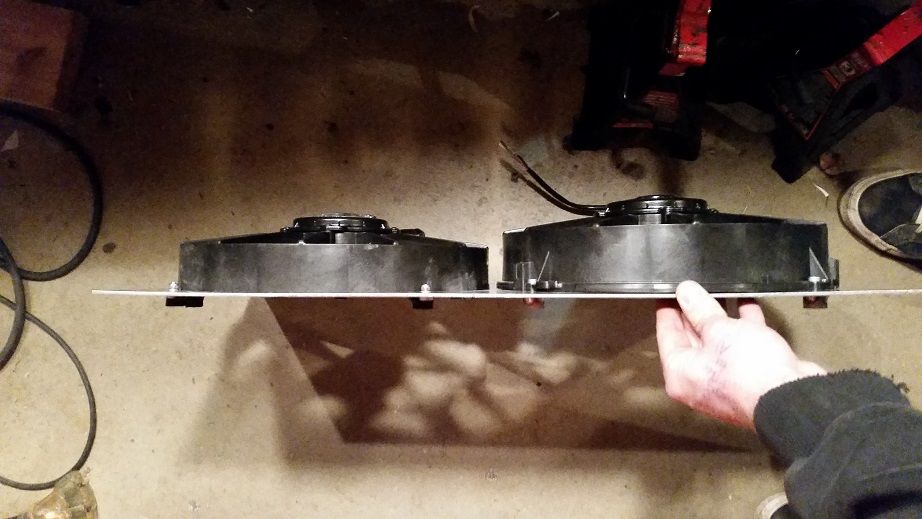
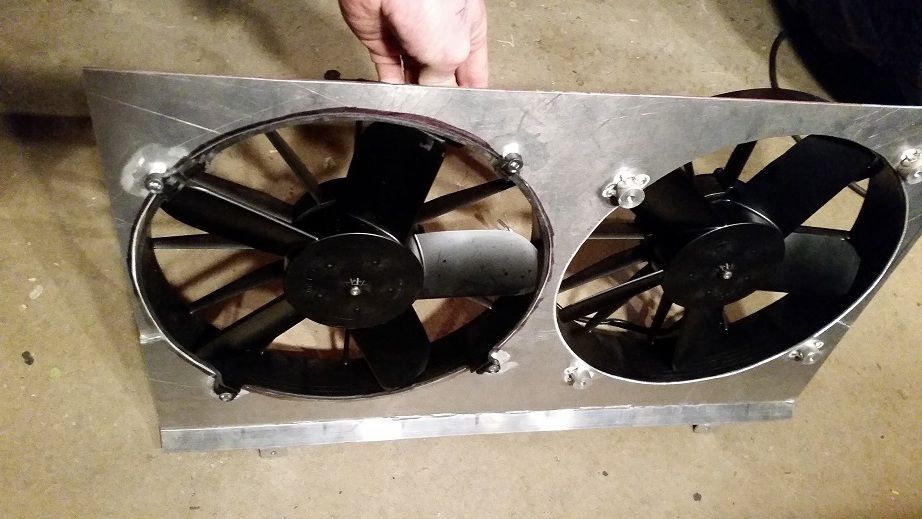
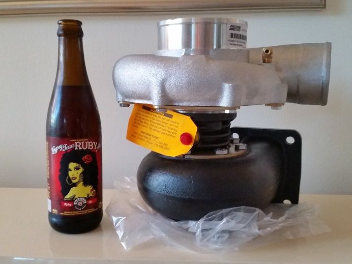
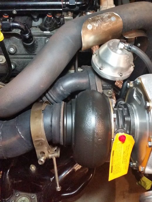
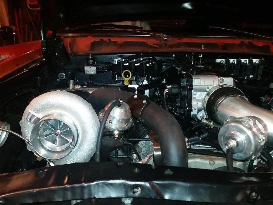
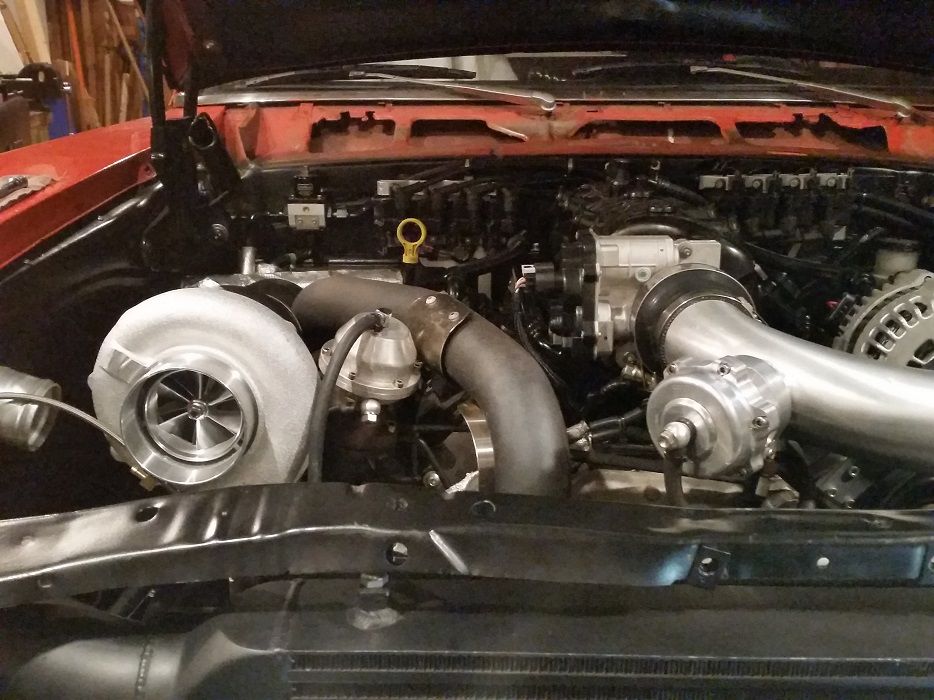
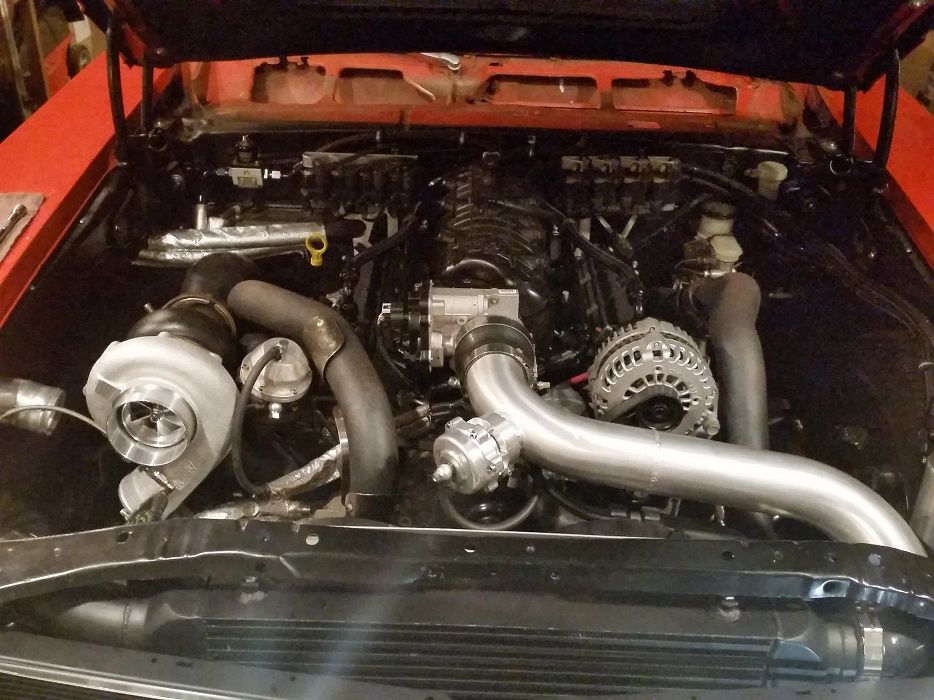
Also picked up my new turbo on Dec 24.. merry xmas to me!! I also got a 800hp Mcleod twin plate RST clutch, a bigger 46mm Precision wastegate, and a turbo blanket. The turbo magically dropped right into the piping I had fabricated around the TC76, so no T4 flange or downpipe vband flange mods were needed. Since the outer diameter of the turbine housing is bigger and closer to the hood, I got the turbo blanket. Finally, the all-important turbo stats are: PTE 7675 CAE CHRA 0.96 A/R.. oi what a mouthful. Translation: billed compressor wheel, ceramic bb center section, and a ceramic coated turbine housing. This thing is gonna be silly.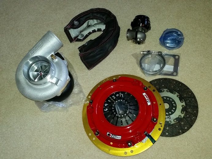
1-2-2015
Install is complete. Ended up being a direct bolt-in on the turbine side which was super awesome, but I did have to make a 3" u-pipe connecting the 3" compressor housing to the intercooler (ignore the temporary gross-looking blue silicone couplers!) where the previous Turbonectics TC76 had a 2.5" compressor outlet, 2.5" u-pipe, and step-up coupler to 3" intercooler inlet.
Started it up and with the BB turbo (with factory Precision oil restricor) the engine was giving 55psi cold oil pressure, 45psi warm, and almost 90psi when revving the engine.. hooray!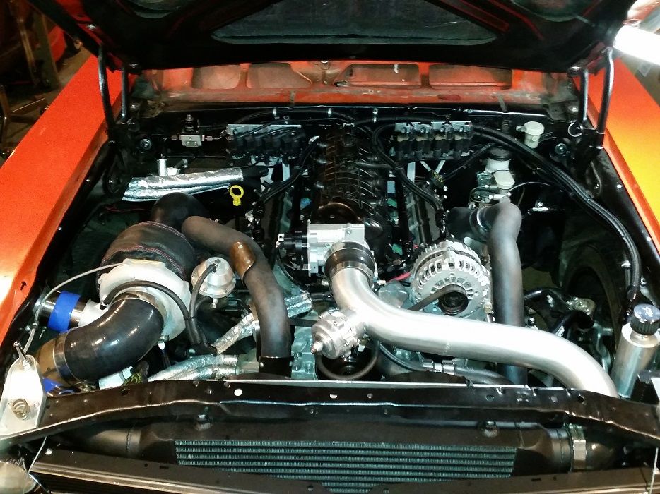
1-11-2015
Well the car has full insurance and plates on it for the first time since.. 2006! I daily drove it for about a full week after putting plates on it. 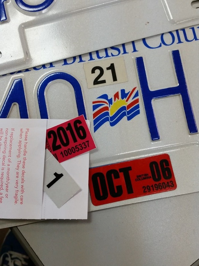
It passed all the required tests:
- drivethru test
- grocery-getting test
- "four spare tires in the trunk" test
- idling and other car guys think "just got a tree-fitty in it" test
- 3rd and 4th gear "highway passing power" test
- "cops drive by it without a second glance or suspicion" test
But then.. the Aeromotive 340 fuel pump fails and leaves me stranded. Need to pull the tank and see if it's the in-tank pump ground or power wiring that's failed, or the pump itself that failed. Either way I have two Walbro 255's on the way so this doesn't happen again. At least the tow truck driver was a cool old timer with a ton of musclecar stories, and was respectful/careful with the car and good with the truck boom..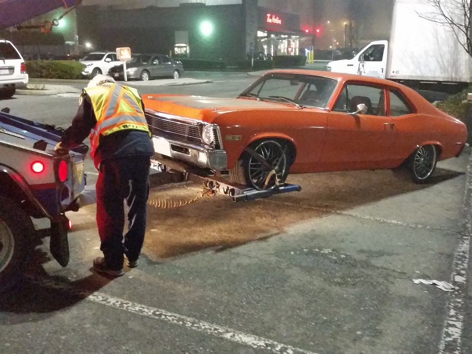
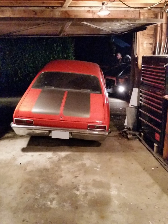
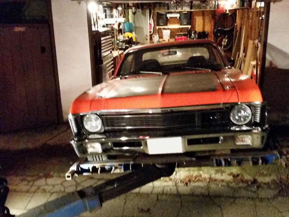
4-21-2015
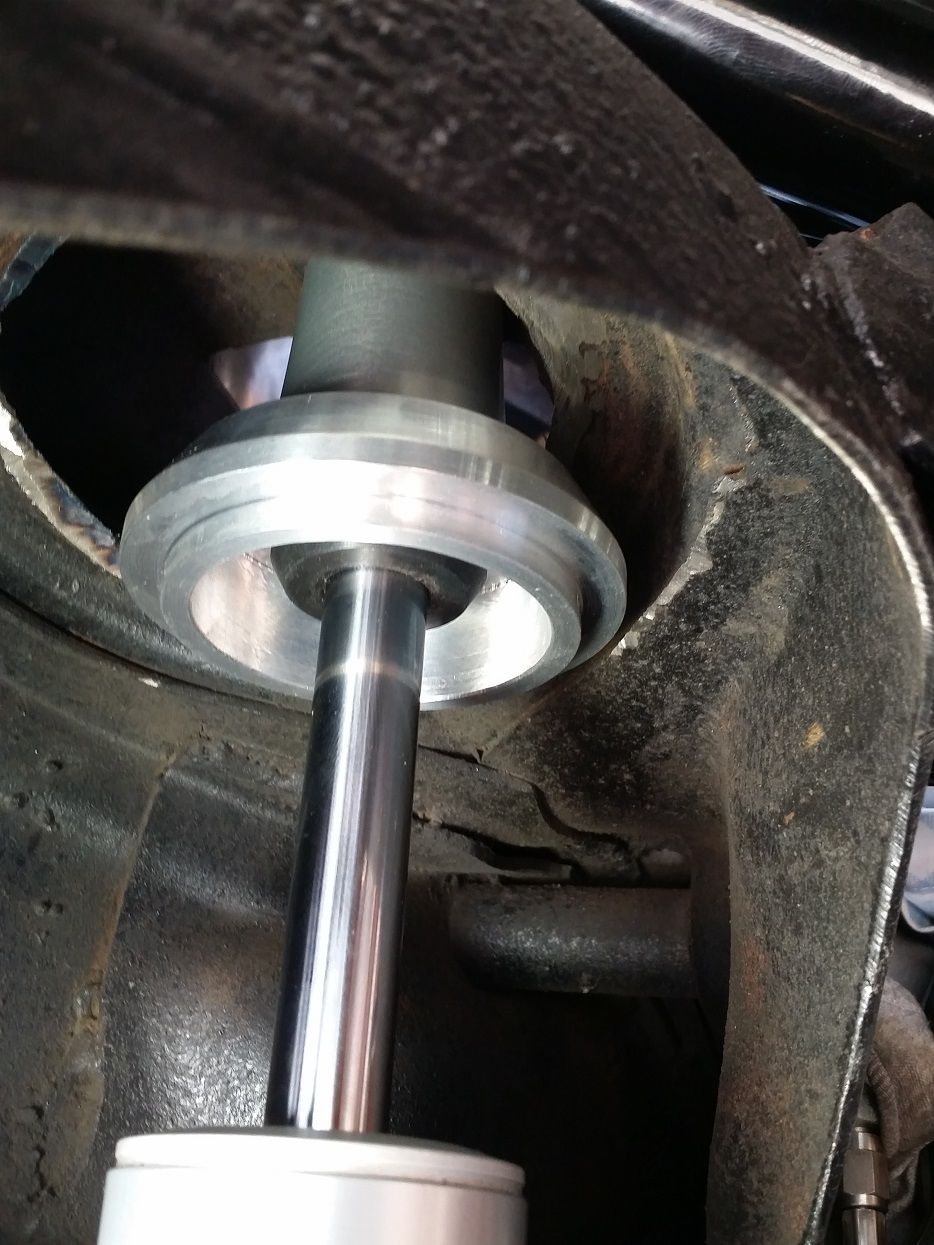
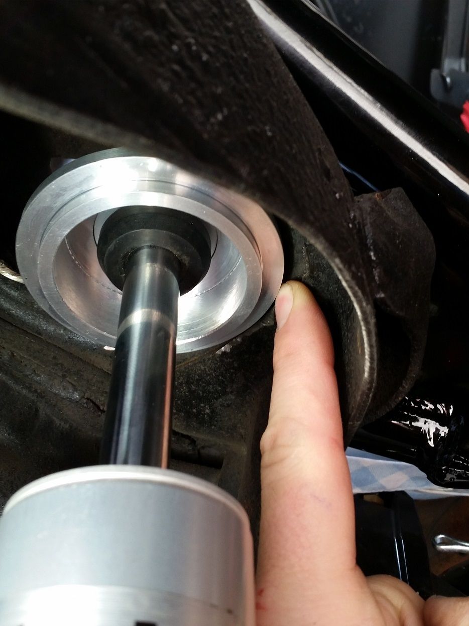
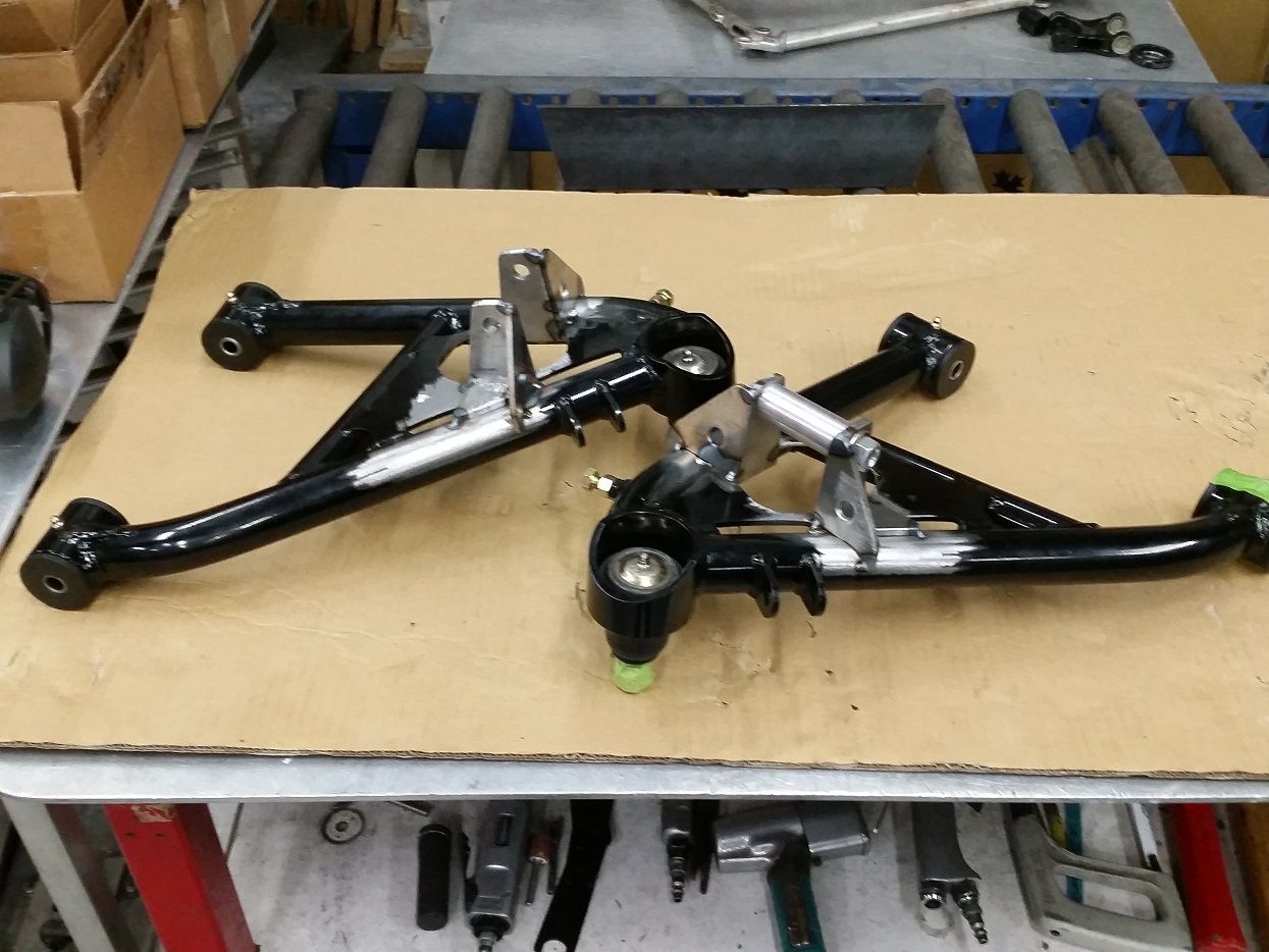
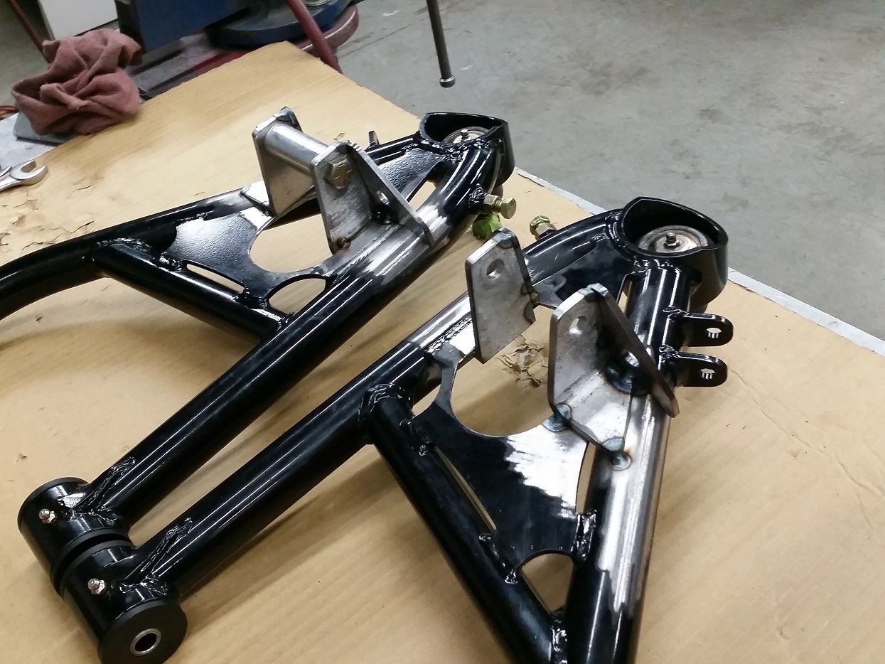
Not much to update. When I got the car off the ground to replace the fuel pump (with 2 more 300lph pumps) I decided to put on high-clearance control arms for the future-planned front rim widening and subframe notching. I decided to do this now because I wanted the front end to sit lower, and the only way to do that would've been to modify my previous standard-clearance control arms.. so decided to sell those and just work over the new arms which I knew I would be getting in the future anyways. The new arms are flat (no droop like old ones, for more rim inner lip clearance) so in order to get the car to sit where I want.. modify brand new arms for correct lower shock mounts.. yayyy!
New...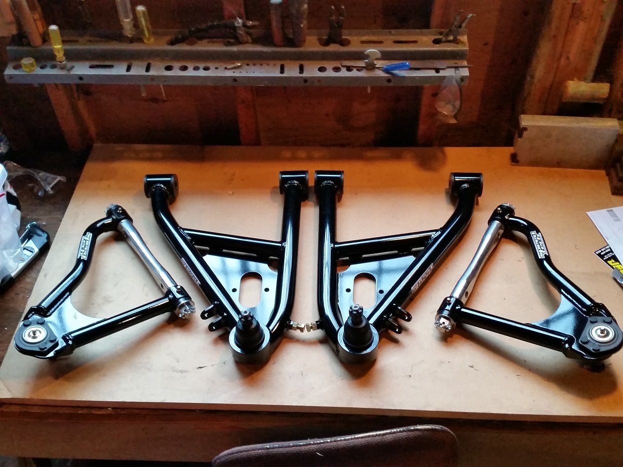
Clearance'd...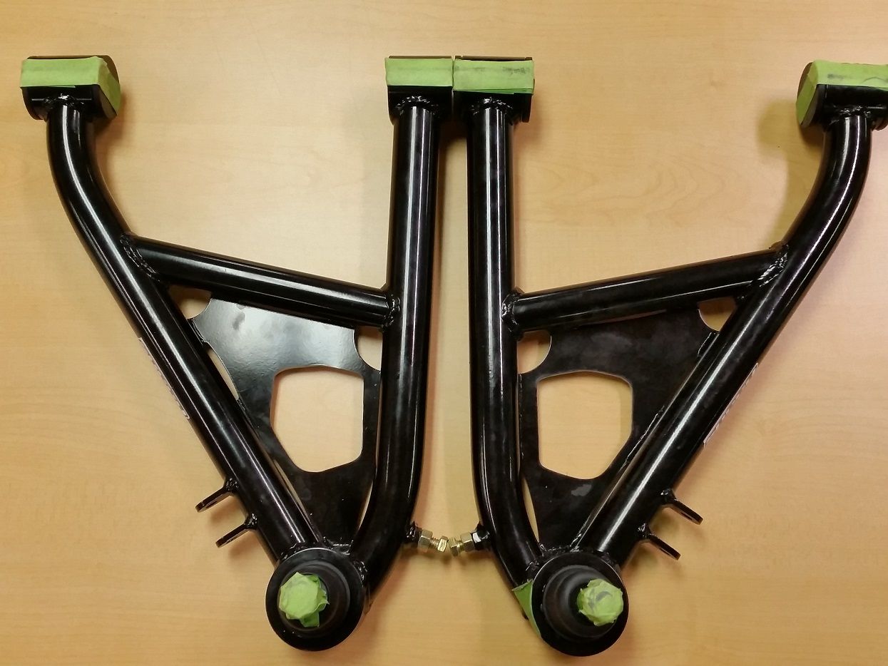
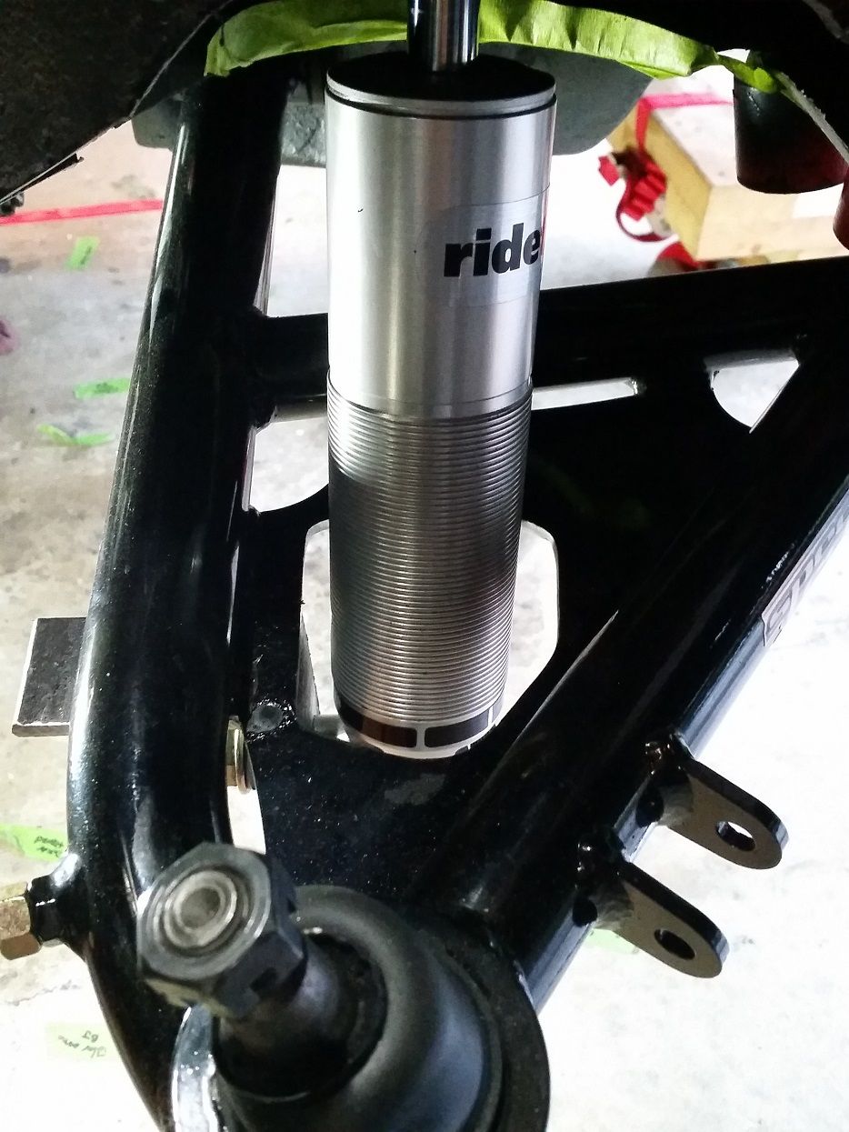
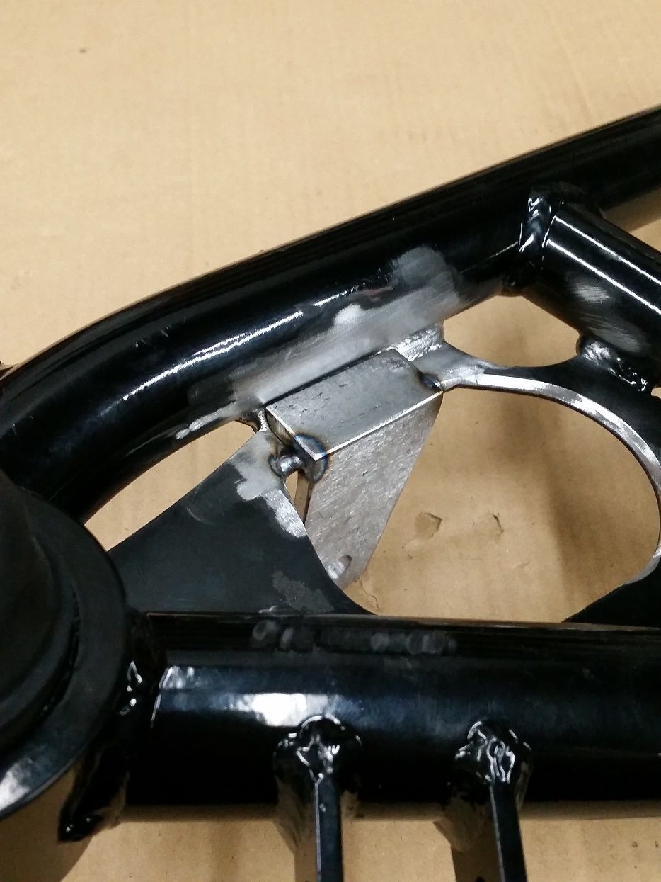
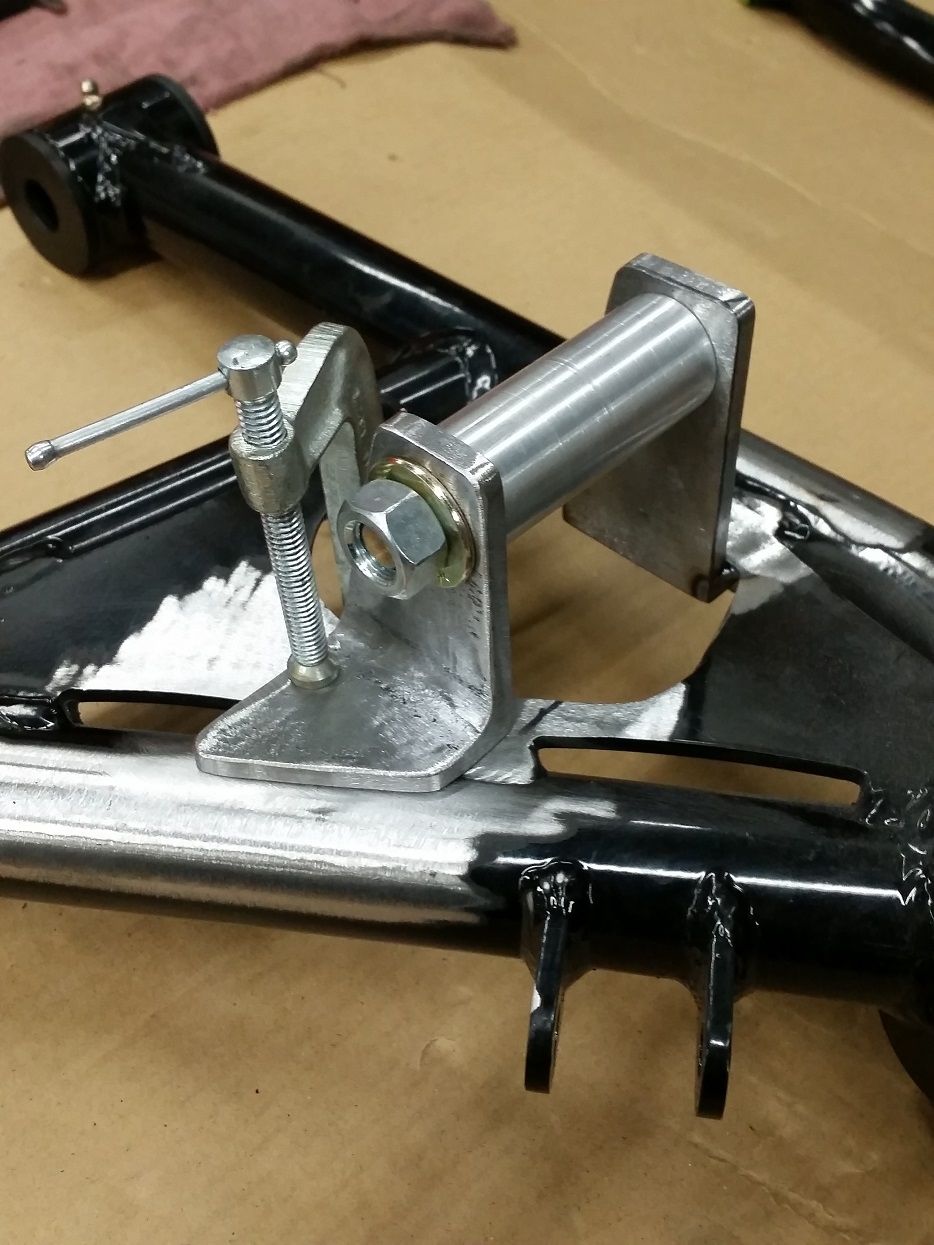
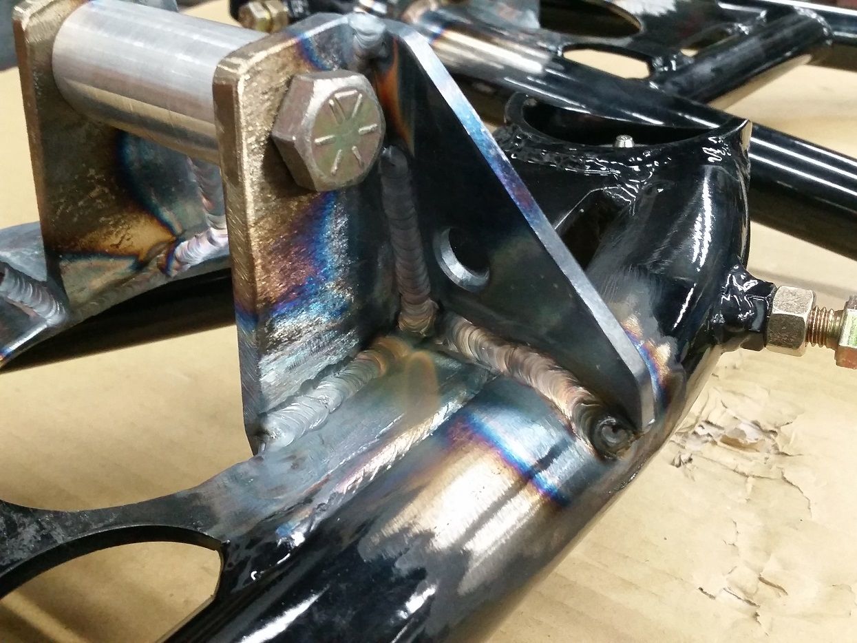
Start of the L-bracketry for the lower mounts. Wanted at least one side to have mechanical purchase on the existing control arm plate, so that the brackets weren't relying 100% on fillet welds in tension (not that I don't trust my welding skills.. just a safety factor)...
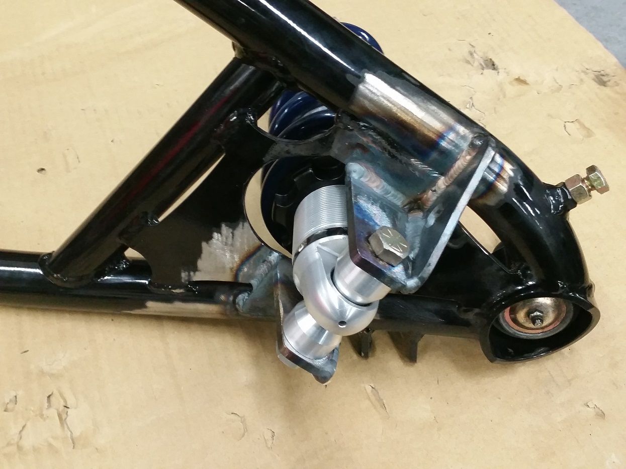
Because of the new angle of the coilovers (lower mounts moved outboard to a 1.45:1 shock-wheel motion ratio from a stock control arm ratio of ~1.75:1), the upper edge of the coil spring would interfer with the stamped sheet metal of the stock subframe spring pocket, as well as the outer diameter of the coil massively interfering with the pass-thru hole in the subframe. So I cut!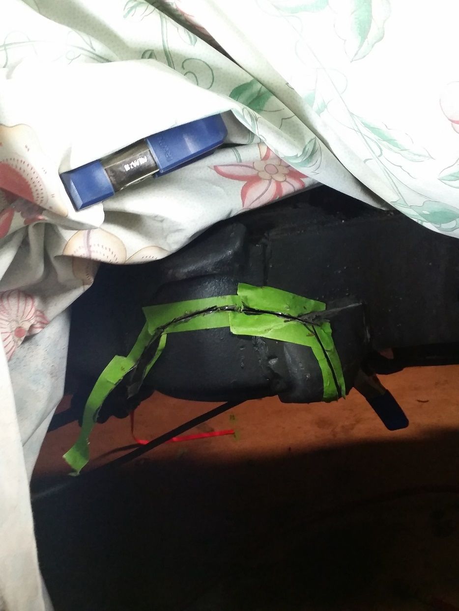
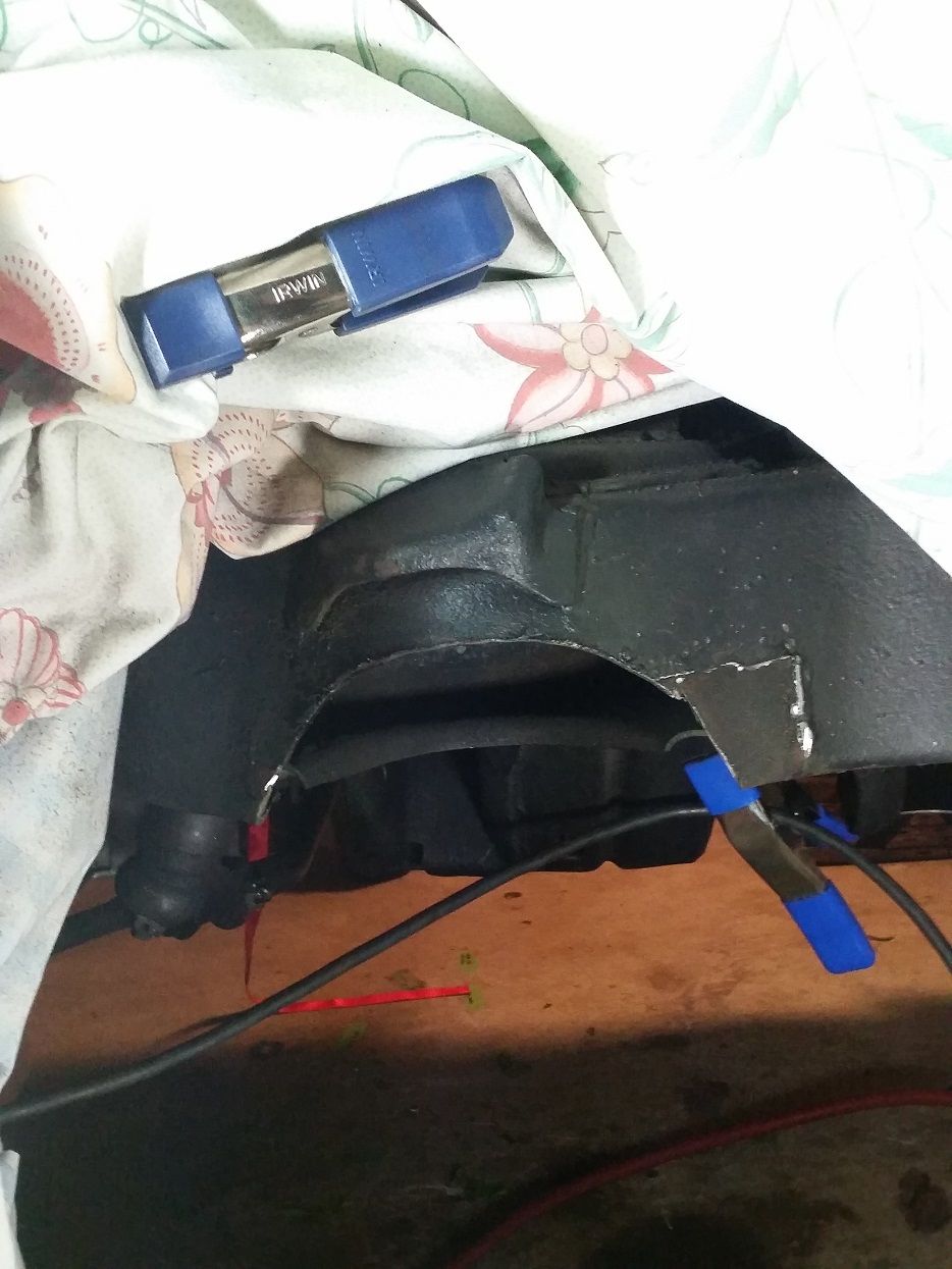
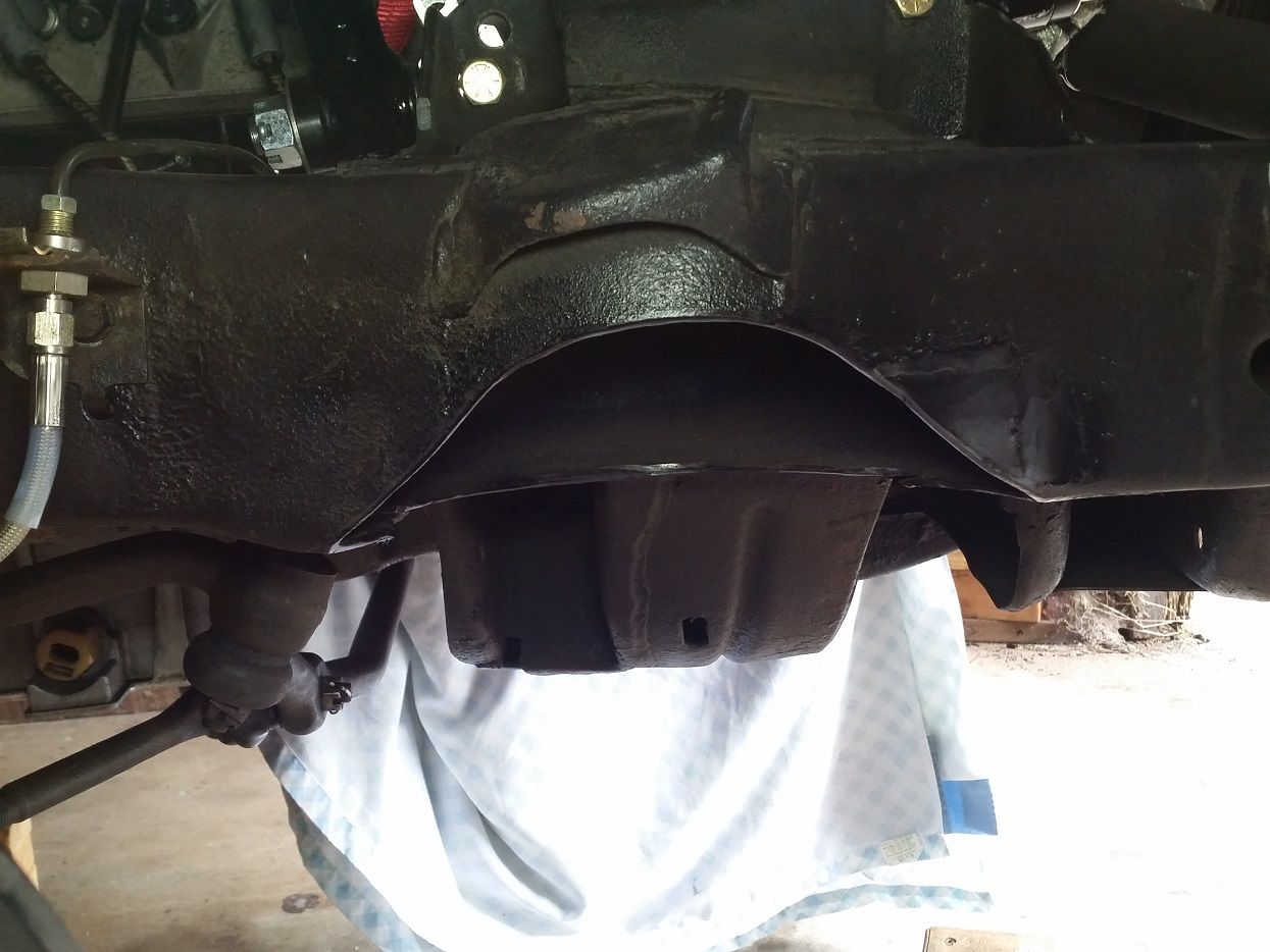
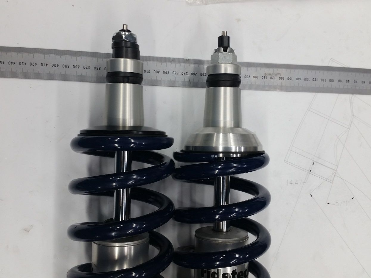
This also involved making new upper spring perches for the coil on the shock body to drop that upper outer edge of the coil spring down ~1/2" to clear the spring pocket on the subframe..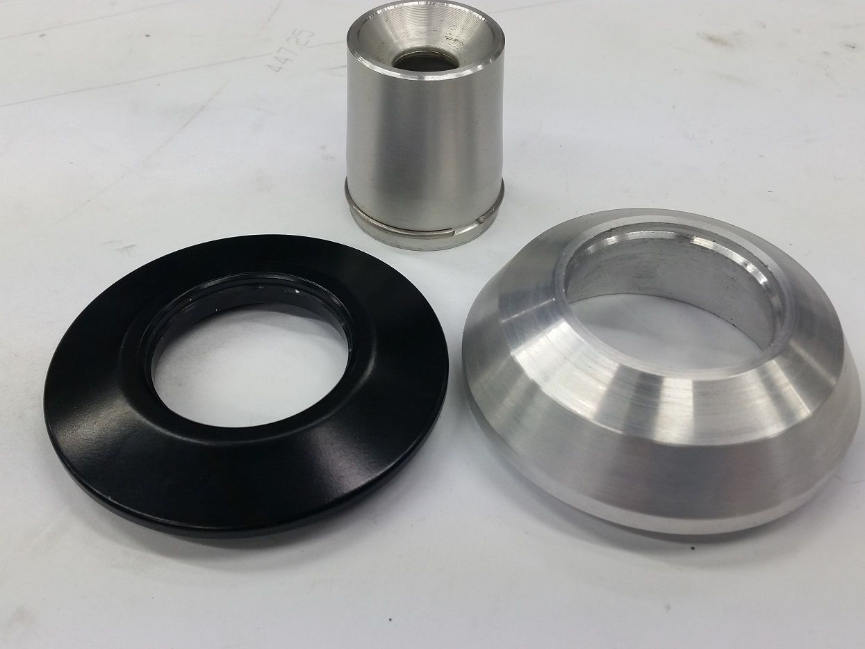
4-26-2015
Needs to be about 1/4"-3/8" higher in the front with trimmed fender lips, and about 1/4" lower in the back. It has a bloody 1.2* stinkbug rake.. it's gonna drive me nuts but I'll just have to deal with it for now and drive it. And have to move the diff forward to center the rear wheels in the wheel wells. oi...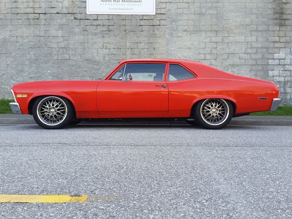
The only two vehicles which I have insurance on are deliciously contrasting...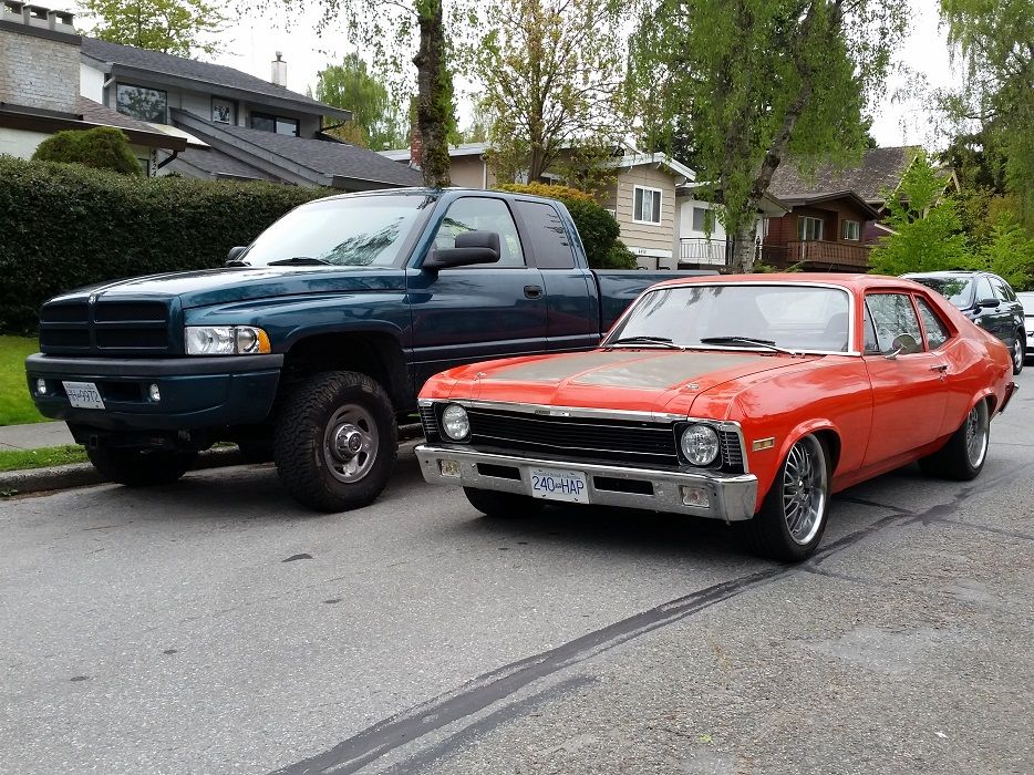
6-19-2015
So I've been fiddling with the car for a while.. not really LS stuff but since all the work I've ever done to this thing is in this thread, I might as well update.
FINALLY got around to putting a carpet in after however many years of just Dynamat on the floor. I originally tried using a repro carpet with little hopes of it actually working, and of course it didn't fit because I raised the trans/driveshaft tunnel to 10"+ above the floorpan. Had to order some yardage of 40" wide 80/20 black look carpet, with a decently thin and flexible rubber backing to it..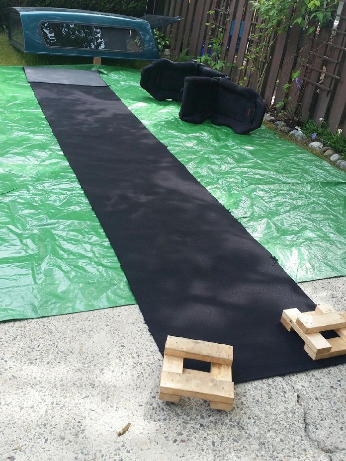
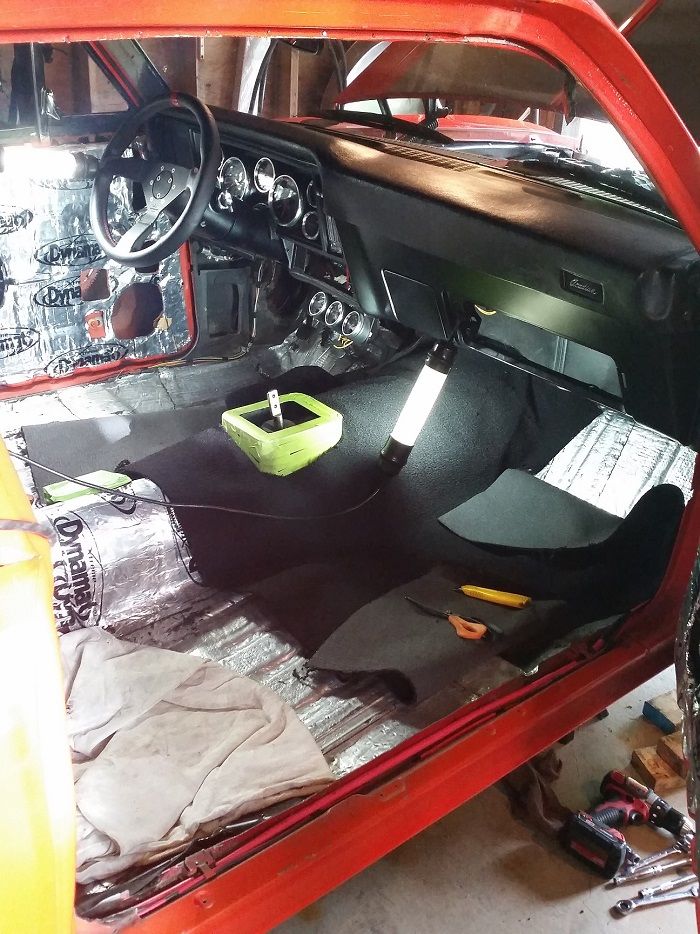
I tried as hard as I could to get it to be 1 piece width-wise with just cut reliefs and heat it to conform around curves, but it just wasn't looking as good as I had hoped, so I decided to make it up from patch panels. I used sticky-backed Velcro to stick one side of the Velcro to the floor, and the other side used as a joining agent. I also used small patches of Velcro to keep the floor pinned down in various areas to prevent lifting or rippling..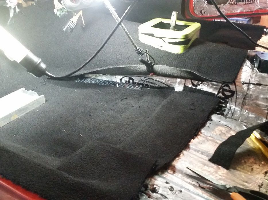
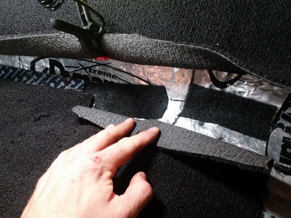
Overall I'm pretty happy with how the joints ended up looking...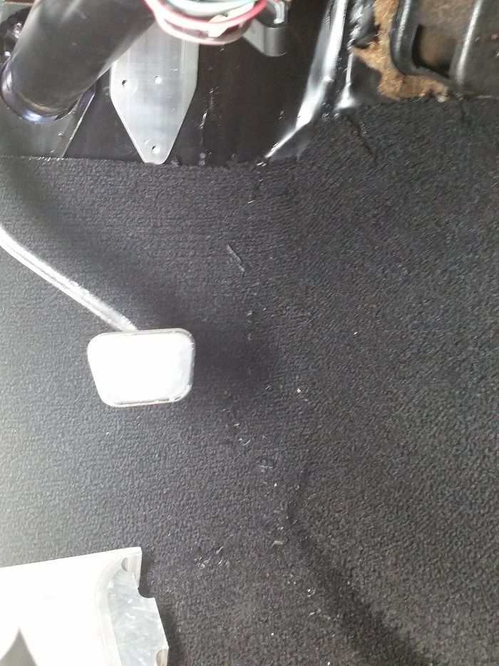
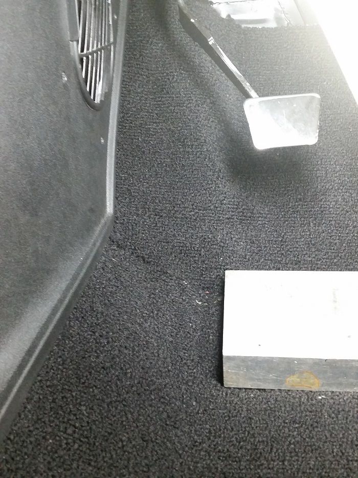
I did end up making a non-hidden seam separating the forward width-wise strip and the rearward width-wise strip, and covered the exposed edge with vinyl end trim to give it a bit of a 60's era look..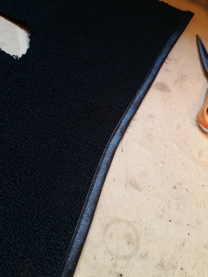
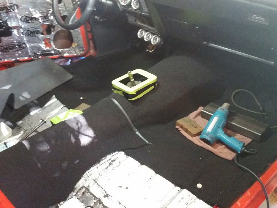
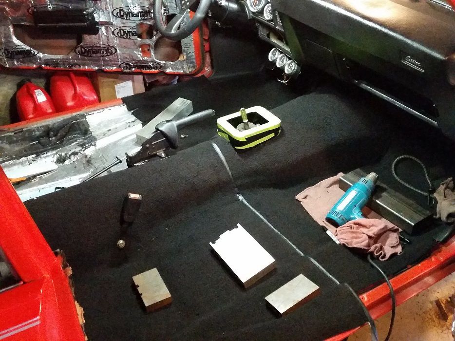
All done after 20+ hours!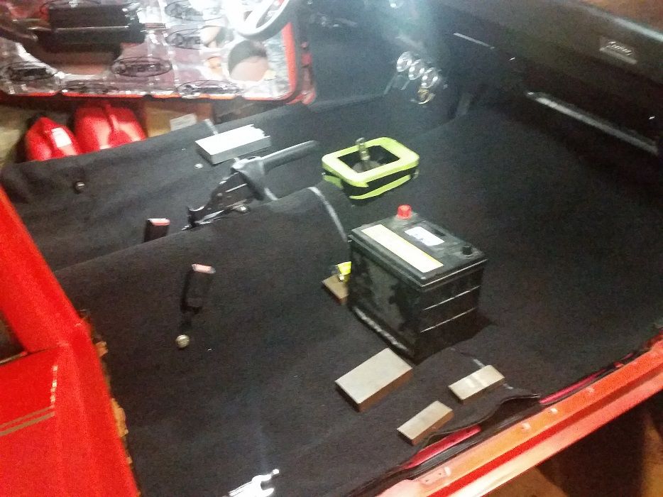
Since the carpet was out of the way, I could finally put in panels and stuff, as I didn't want to install anything scratchable before the carpet was in as I knew I'd be going in and out of the car a shitload of times while doing the carpet.
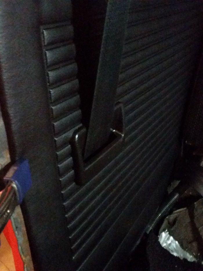
Reminder of how I installed hidden retractors for the seatbelts..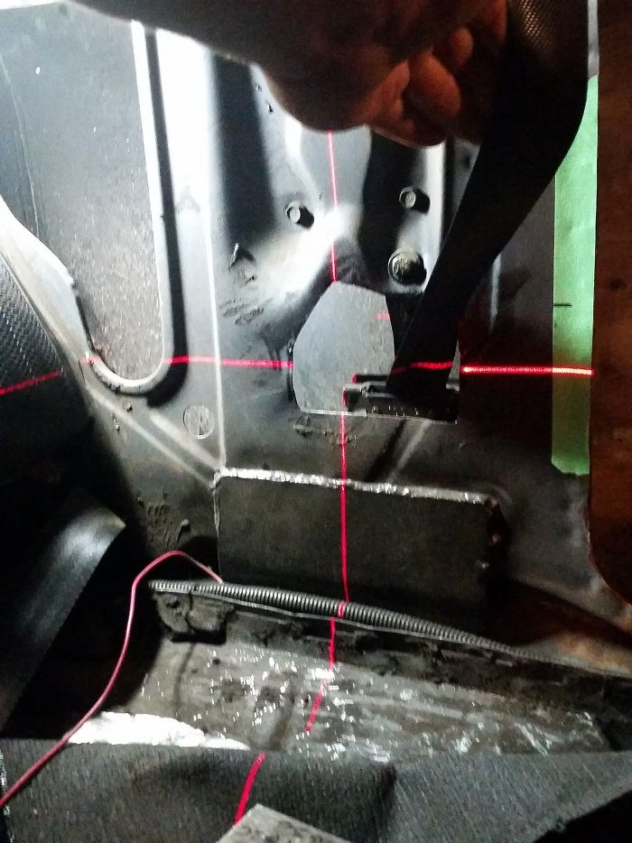
Nothing like cutting right into brand new stuff..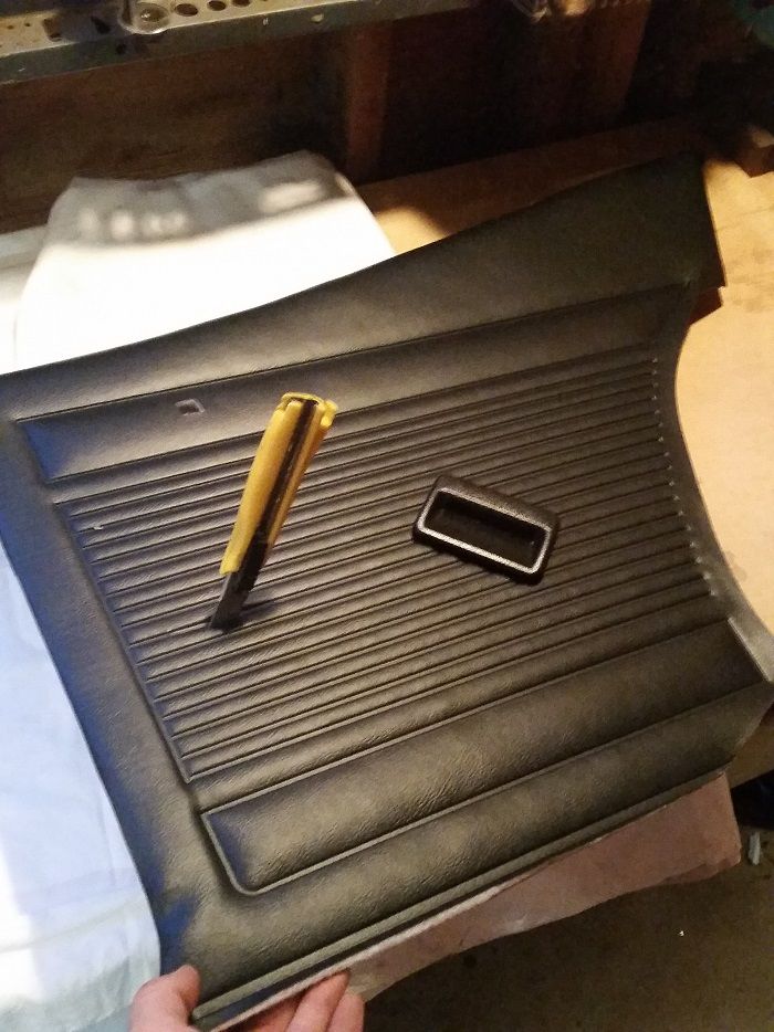
Luckily it worked out well. The trim pieces are from the rear seatbelts on a 90's Isuzu Trooper (where the belt goes thru side paneling into hidden retractors)...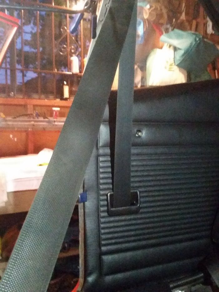
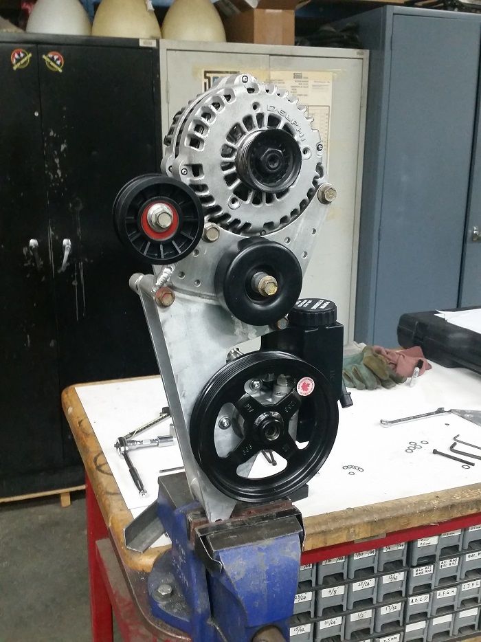
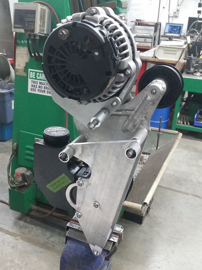
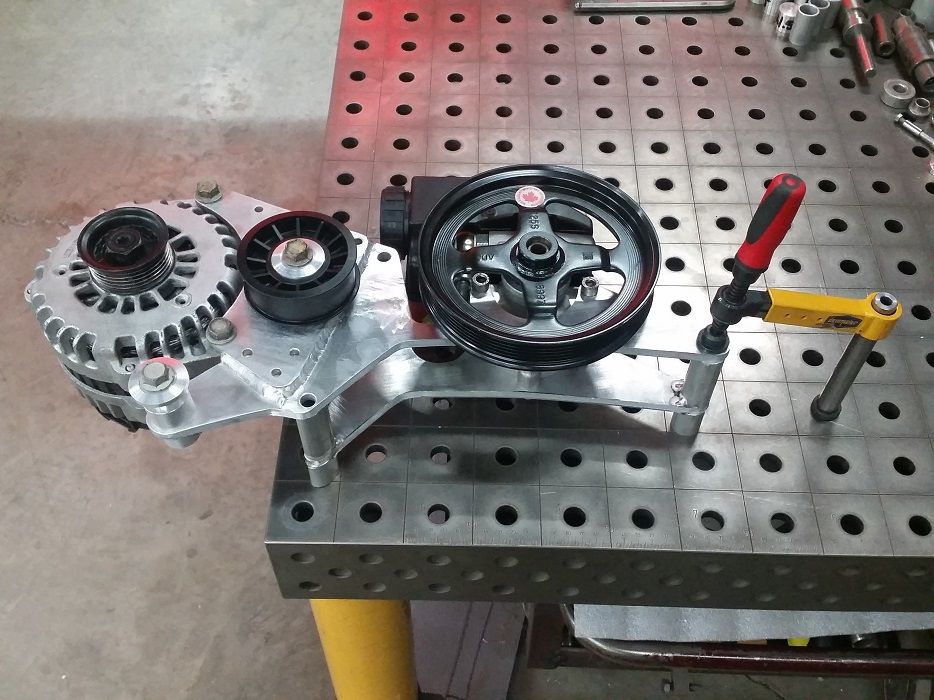
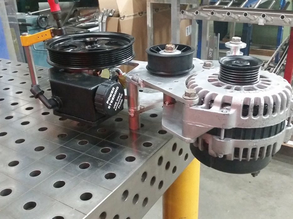
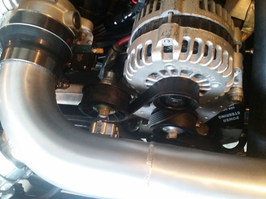
I also wanted to upgrade the power steering pump to a newer lower-flow GM Type II pump, as the stock truck pump felt like it was overpowering the box a bit giving a vague feeling, as well as being massively squeely and annoying despite my best bleeding efforts. And the ancient Saginaw P pump with its cast aluminum bracketry was massively heavy!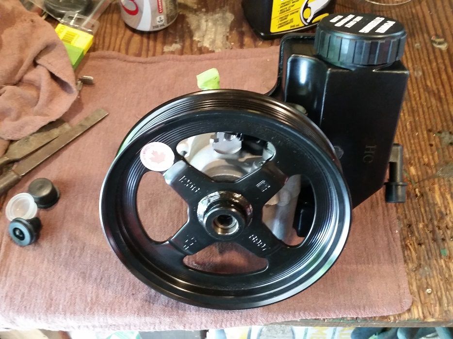
6-22-2015
Did any of the info in this post help?..
LQ4 into a 3rd Gen/1972 Nova
The fans are this unit:
http://www.summitracing.com/int/part...6142/overview/
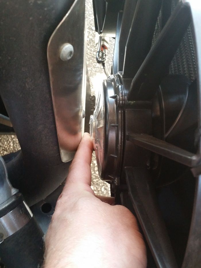
I've found real inconsistencies with "thickness" measurements on Summit, with prettymuch every fan being 2.1"+ thick. Some of the more expensive "slim" fans are even thicker than this one! The fans are reasonably loud, but once the hood is closed and I'm out on the road, even in traffic, I can hardly hear them. I idled in a bunch of traffic with ambient temperature being pretty hot and ECT never creeped above 200*F. Any movement whatsoever and it dropped quickly.
There is about 1/2" clearance between my [heat-protective taped] fan motor and the heat shield. I haven't experienced any fan issues or any plastic melting, so will see how long it lasts.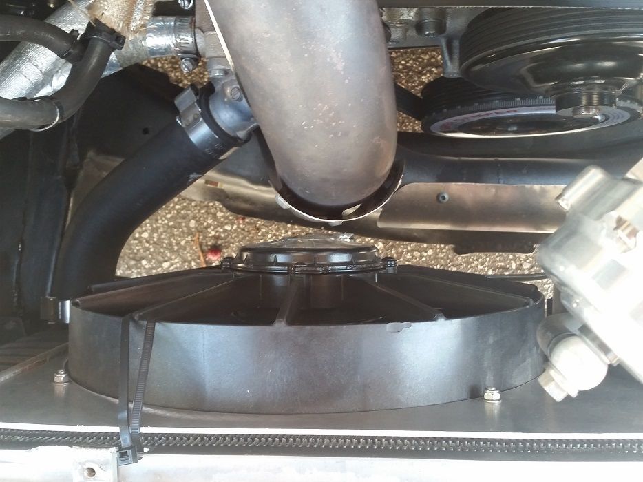
6-26-2015
It is pretty thin.. just a single-row's thickness, so we'll see how it handles. I really don't have any room for a thicker rad unless I completely change the intercooler configuration and/or move it somewhere else in the engine bay.. these stupid Nova's have so little forward room!
In other news.. it finally happened! It was so fun to FINALLY line up next to Mark window-to-window after all these damn years haha..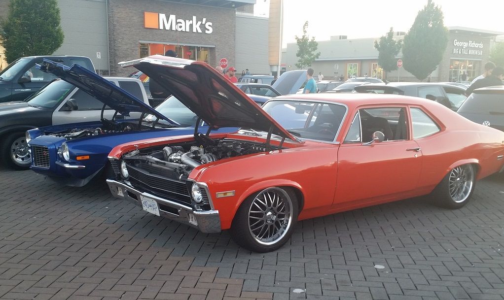
7-21-2015
Haha yeah it's working well now. Just been driving it around, to work, groceries, late night fun etc. I may auto-x it but no road course yet since it doesn't have a sway bar anymore. I'll be waiting until winter to fabricate a new narrower 3-piece sway bar at the same time that I widen the front wheels and [likely] notch the subframe. And also remake my exhaust from turbo-back in 3.5" stainless to replace the restrictive 2.5" temporary setup I'm running now. I can now hit 16psi of boost whenever I want, but the car starts pulling less and less after 4500.. I've really started to notice how much the exhaust is choking it up. Oh well at least I can drive it!
11-3-2015
So the girlfriend was asking whatever happened to "that internet post about your car" and I realized, I haven't posted on here in a while. I guess no news is good news.. just been driving it tons the summer/fall. The Nova's name is Roxie and she likes adventures.
She likes hanging out with her friends..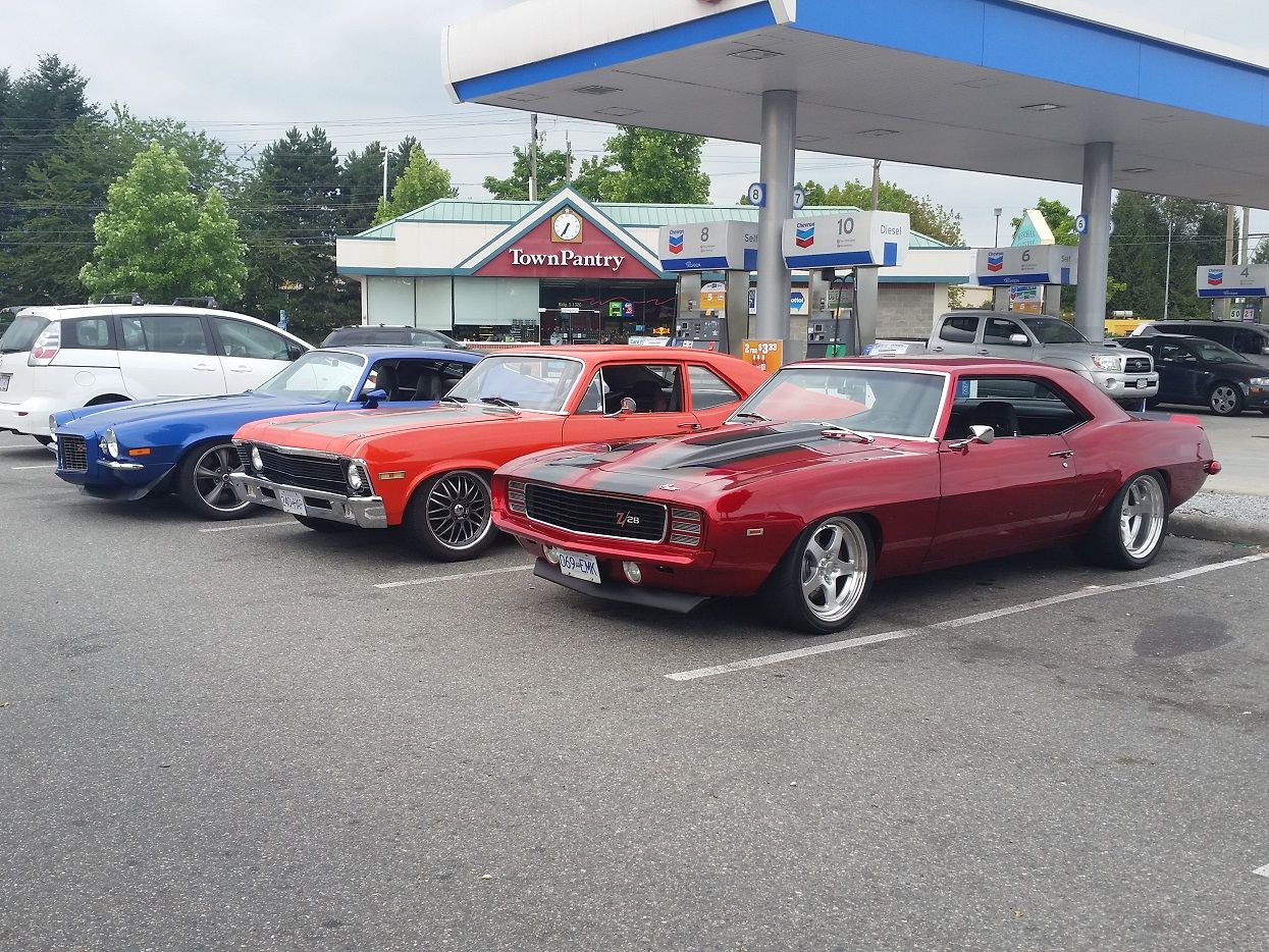
She has a crush on this blue stunner. I won't tell Mark though..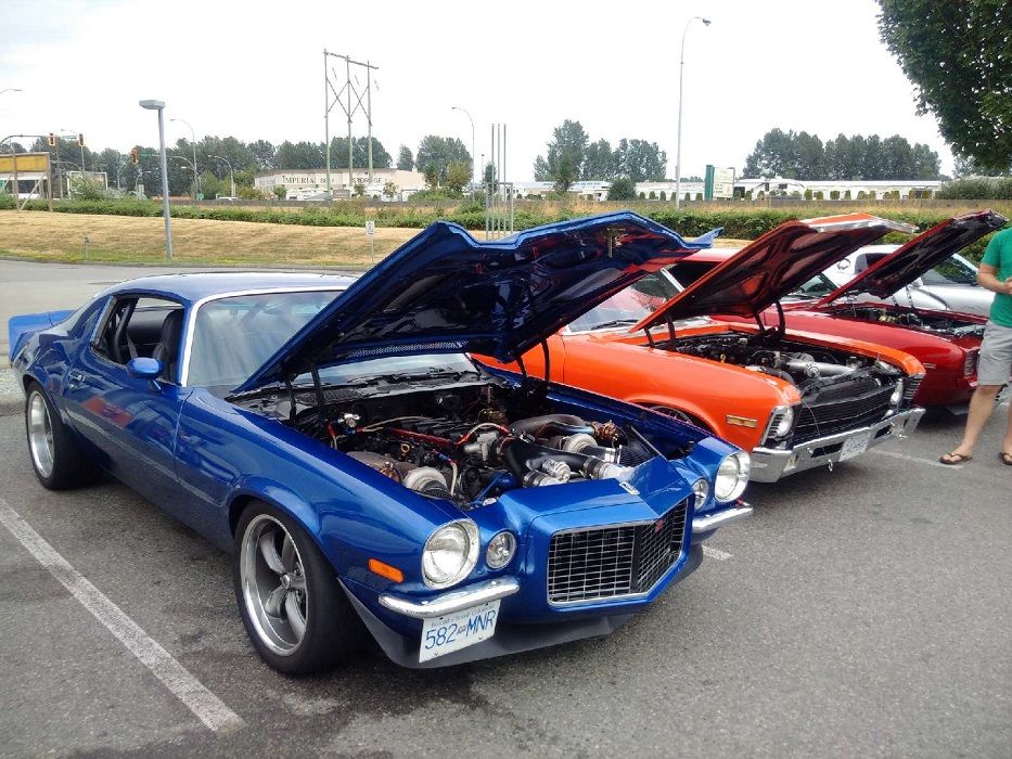
She likes to show off her big booty...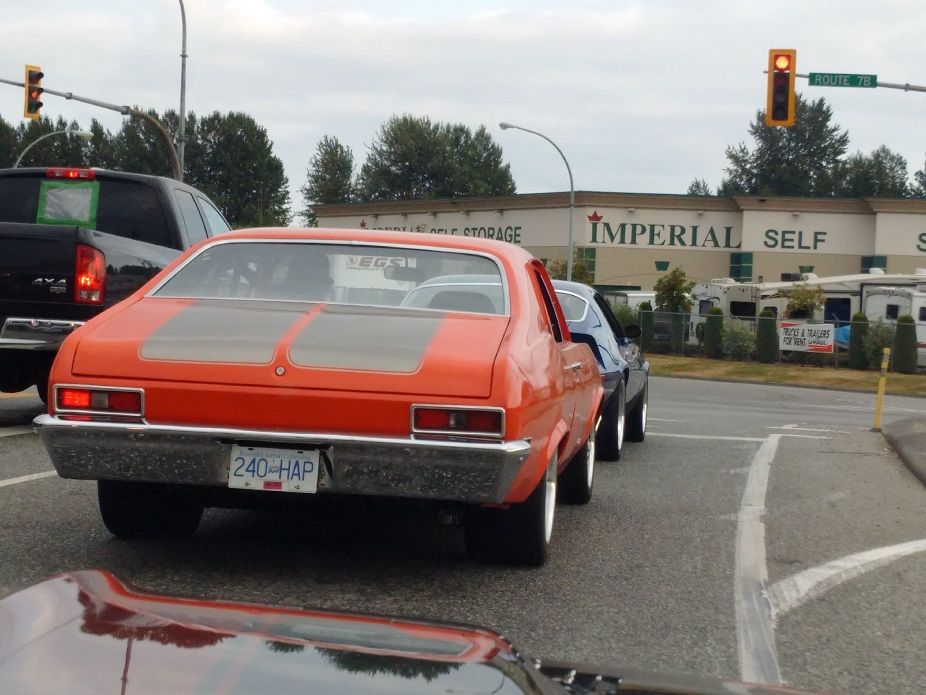
She's okay with being used to go get tools and other cool errands...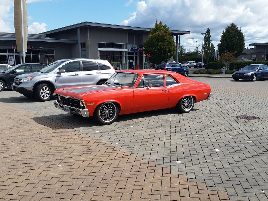
..but she prefers to run beer errands instead...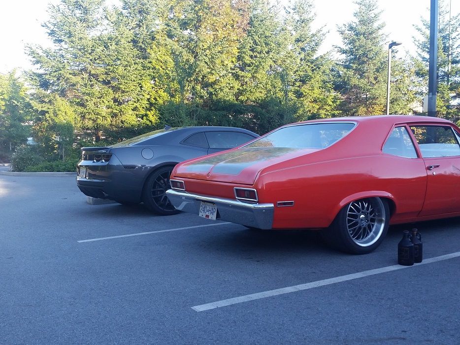
Sometimes she gets caught in the rain, but she doesn't seem to mind getting wet...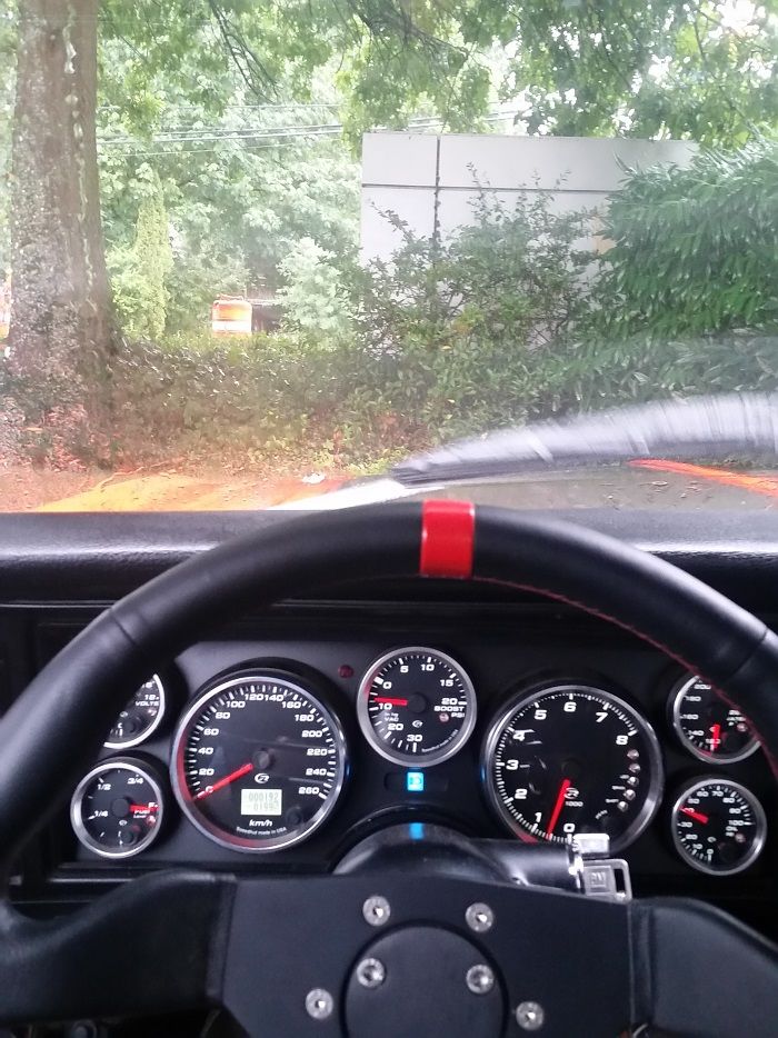
Other times she gets abused on long hill climbs for the reward of nice views...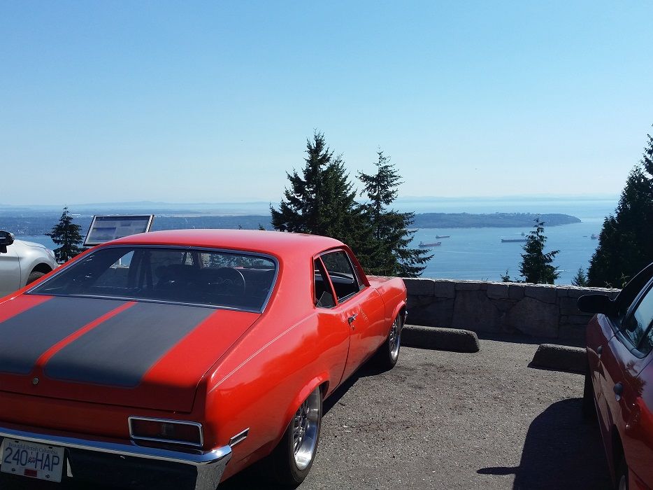
But mainly she just likes being used after so many years of being garaged!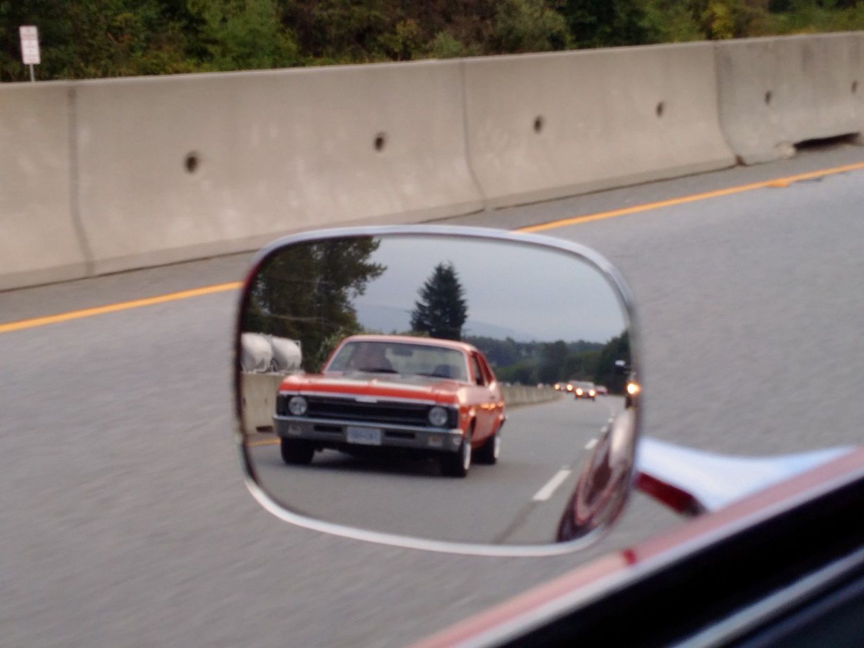
11-3-2015
Hey Kirk,
Thanks! It took me a long *** time to get the static stance where I had always envisioned it with no rubbing during bump/articulation or cheating with airbags.
The only time I ever scrape is cresting up and over the hill at the top end of the alley behind my parents' house, but going over speedbumps or raised manholes it's never an issue. Ill measure it but I believe I have 4-4.5" ground clearance across the floor.
I don't recall the fender lip height measurements off the top of my head so can measure those for you too, but I don't have full turning lock.. maybe only 3/4 of the factory turning radius. To help with this I could:
- more negative camber (don't want to since it's a street car)
- higher front rim offset (don't want to since the track width looks spot on IMO)
- raise the front of the car (haha.. NOPE)
- trim the inner lip of the fenders (have been meaning to do this all year but just too lazy)
Cheers,
joe
12-3-2015
Hey Kirk,
Sorry it's taken so long to get the height measurements.. I just kept forgetting!
Front = 22 5/8"
Rear = 21 7/8"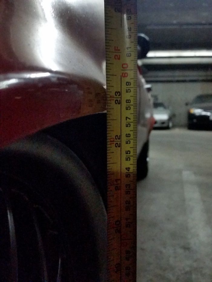
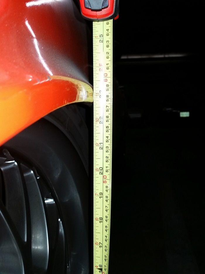
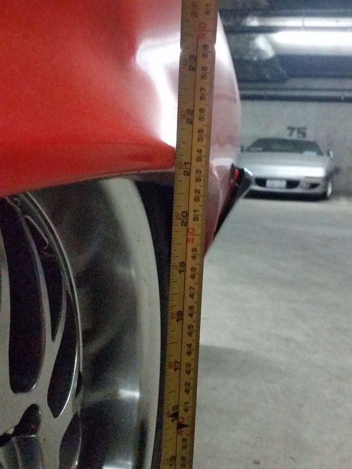
1-9-2016
I just like DBW for sure! It's easier to do cable TB, but this way it's all wiring and no extra holes in the firewall or a mechanical pivot.. I have the DBW pedal bolted to an aluminum plate, which is then separately bolted to the firewall with standoff spacers so I can totally fine tune the location of the pedal in all directions relative to the brake pedal.. it only took 2 tries to get the pedal exactly where I want it!
Since I've received a bunch of positive comments on the ride height of the car, and with Kirk's ride height question, I thought I'd post here my suspension fiddlings from this afternoon.
I jacked the car up level and supported it on 2x4 "stands", but with the front wheels on swivel caster'd dollies, and cycled thru the steering to take clearance measurements and find steering angle for full lock both left and right. At the ride height I have been driving all of 2015 (front fender lip 22 5/8" and rear fender lip 21 7/8"), the steering angle was ~21* before the tire outer sidewall would rub on the fender inner lip.
I then jacked up the car the required amount (only 0.25" higher) to achieve full mechanical steeringlock at the same point that the tire outer sidewall touched the fender inner lip. This only improved the steering angle to ~25* both direction lock-to-lock limited by the steering box.
This is all with untrimmed fender inner lips, using a 12.7:1 power steering box with [EDITED: long 6.0" slow ratio manual steering arms and short 5.25" manual pitman/idler arms].
The wheels used for all of these measurements are 235/45/18 tires on 18x8" rims with equivalent backspacing of 4.75" ("equivalent backspace" value takes into account the 0.75" aluminum slip-on spacer I have on it).
Here are all the measurements I took for the "2015 driving ride height" and "raised" conditions. There's a bunch of info in here but it does include the tire clearances for the 235/45/18 tires to the subframe for the listed steering angles: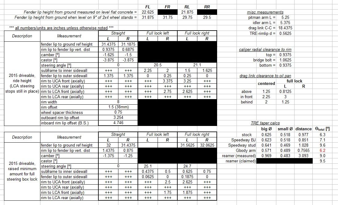
1-13-2016
Good to talk to you again! How goes the Camaro?
What steering box do I have? Good question... I think it's a 1st gen Camaro 12:7:1 box, but that was ordered off of eBay probably a good 10 years ago so who knows if that's accurate.
What's next for the Nova is a whole shitload of things that I've needing to do for a while, like rewiring the speedo output from ECU to make it actually work, remake exhaust in 3" or 3.5" stainless oval from downpipe to rear quarters, finish my modifications of the front bumper brackets to make the bumper level, get a high-flow BOV, grease all suspension pivots, rewire oil cooler fan relay, and a whole bunch of other stuff that are small or that I'm forgetting.
Of course I ignore all that as I have already been doing, and I'm gearing up to stuff 275's on the front. For my ride height I simply can't bump the wheels outboard any more, so I'll widen inwards 1.5" bringing the rim up to 9.5" total width. This will make the rim inner lip interfere with the outer tie rod end. I'm prettymuch mimicking the Ridetech TruTurn by using flipped G-body steering arms that raise the outer TRE's up 2". Of course this means the inner TRE's need to go up as well, but I also want to minimize the bumpsteer so I'm making a bumpsteer gauge to check. I'll tack-weld a plate onto the top of the drag link, and clamp the inner TRE in various new X & Y locations to test which yields the least bumpsteer at my low ride height, with the new G-body steering arms. Once a location is found, I'll weld 3/4" plate to the drag link, add a center reinforcement ridge to the top of the drag link and extra gusset plates etc to ensure strength, then drill & ream the inner TRE tapers.
Since the outer TRE goes up 2", of course this puts it exactly where the caliper is. My 13" rotors are getting worn, and I've wanted a bit of a step up in braking power especially since I'll have more front rubber, so I'll kill two birds with one stone.. make a new half caliper bracket for the Wilwoods to not only rotate up to clear the raised TRE, but also radially out for the bigger rotor. Phewf that's a lot of work!
Initial measuring of what was in my last post..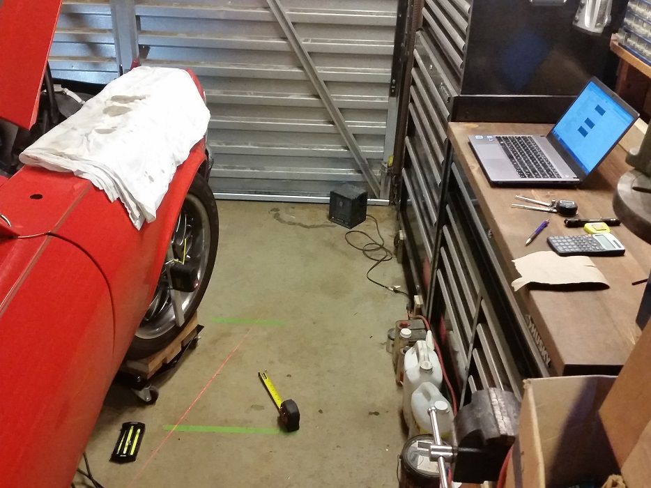
Front of tire clearance at full mechanical box lock..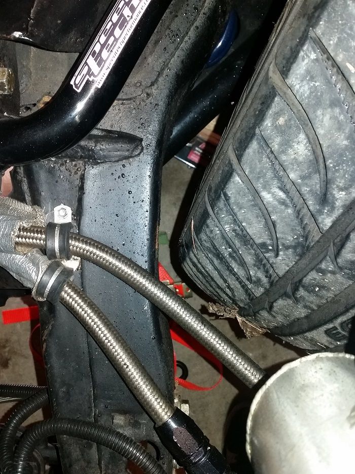
Back of tire clearance at full mechanical box lock..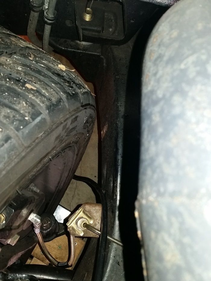
Back of tire clearance at full mechanical box lock..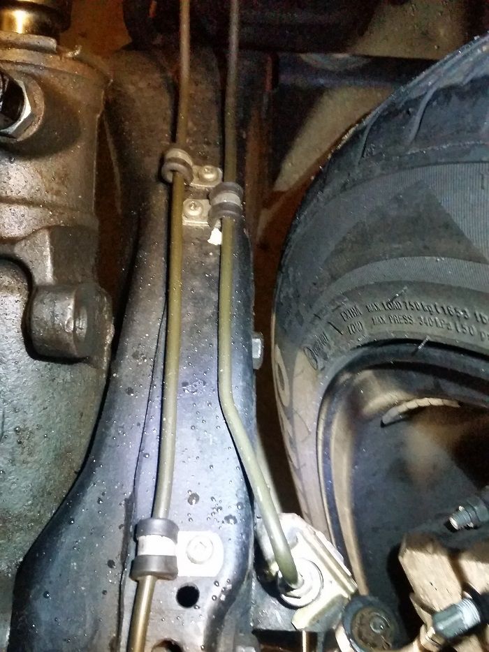
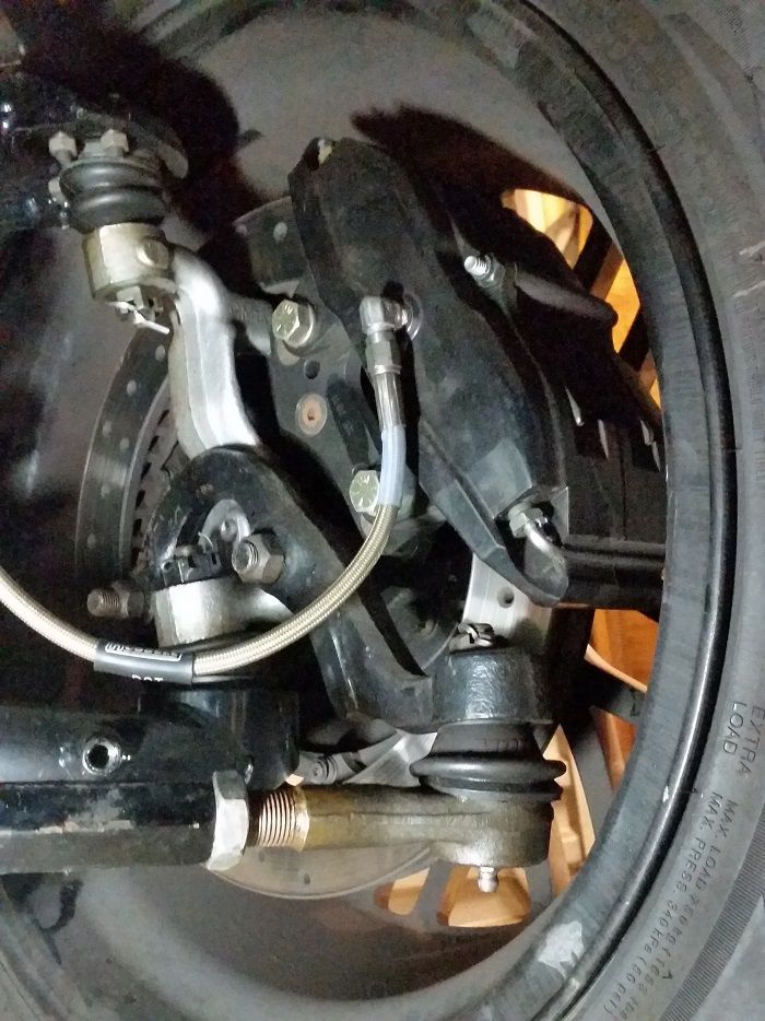
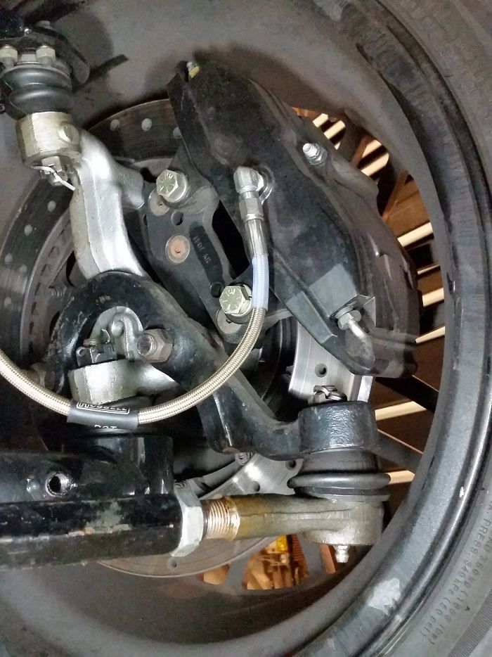
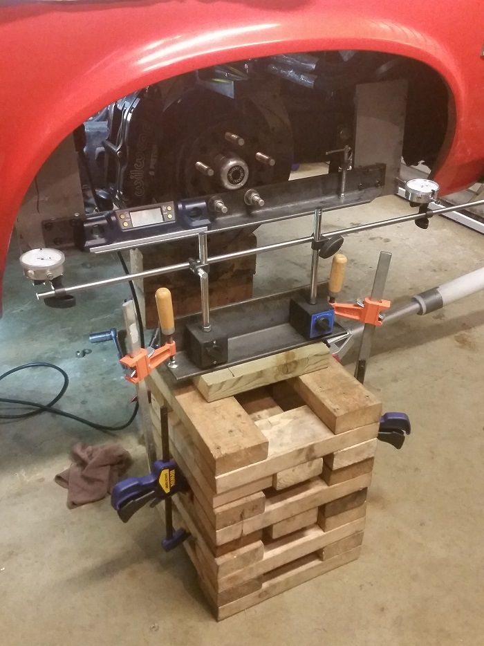
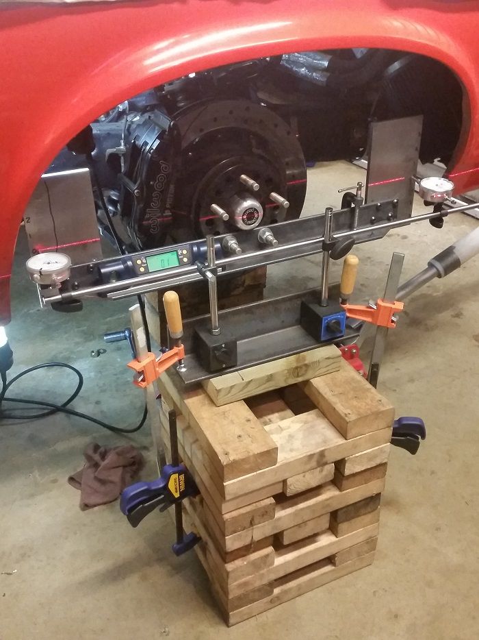
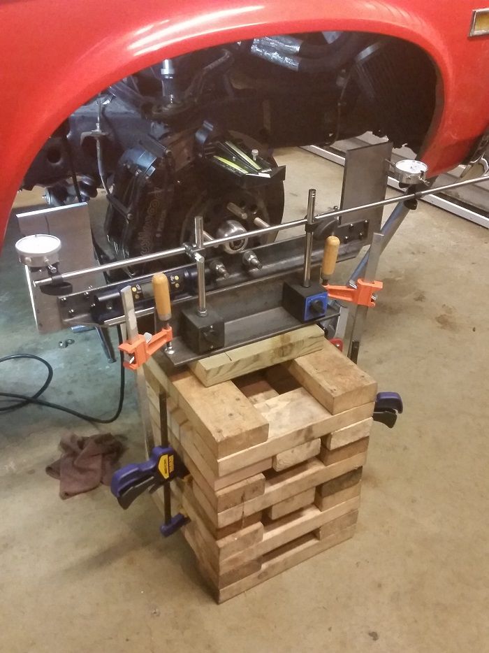
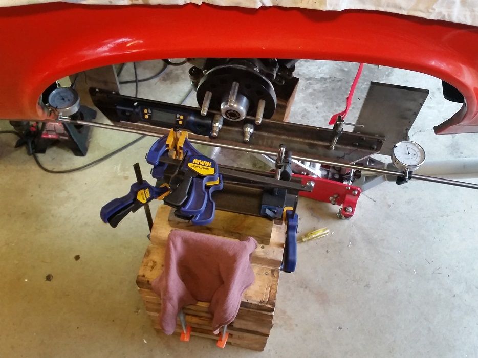
Start of the bumpsteer gauge, still need to make a T-bar platform for the two dial indicators needed, as well as accurately scribe lines onto the aluminum guide plates...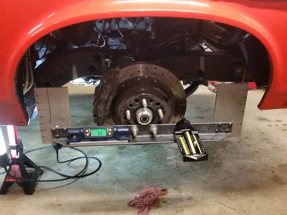
1-14-2016
But scrub radius! Also.. that means I'd have to touch the body for bodywork.. and I'm hastily avoiding that task.
I'll leave my aspirations of widebody awesomeness to a future project.. an e30 bimmer done up boxy 80's DTM style like this Lancia was...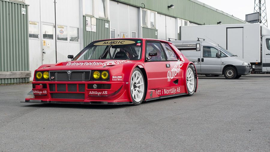
I started plotting out points the other night.. will continue that tonight or on the weekend. 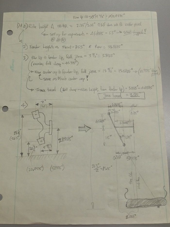
I'm curious what the scrub is too. David Pozzi posted that the SAI for this front suspension (1st gen F-body & X-body) is 8.75*. Apparently the convergence point for the lower control arms on our Nova's might be different than on the Camaro's.. someone was measuring the differences between a 1st gen Camaro subframe and a Nova subframe and noted that the angles and locations of the pivot holes for the LCA's were different.. David Pozzi thought that maybe this was because the convergence point was designed to be at the rear diff center, and since a Nova is longer this meant the LCA lower pivot axle is at a lower angle relative to the center plane of the car. If true this would be beneficial for us Nova guys since the "67-69 Camaro and 68-74 Nova" control arms are likely designed off a Camaro subframe, giving our Nova's more static caster and dynamic caster gain when the Camaro arms are used on our Nova subframes. Anyway who knows if this is actually true or even makes a difference..
1-15-2016
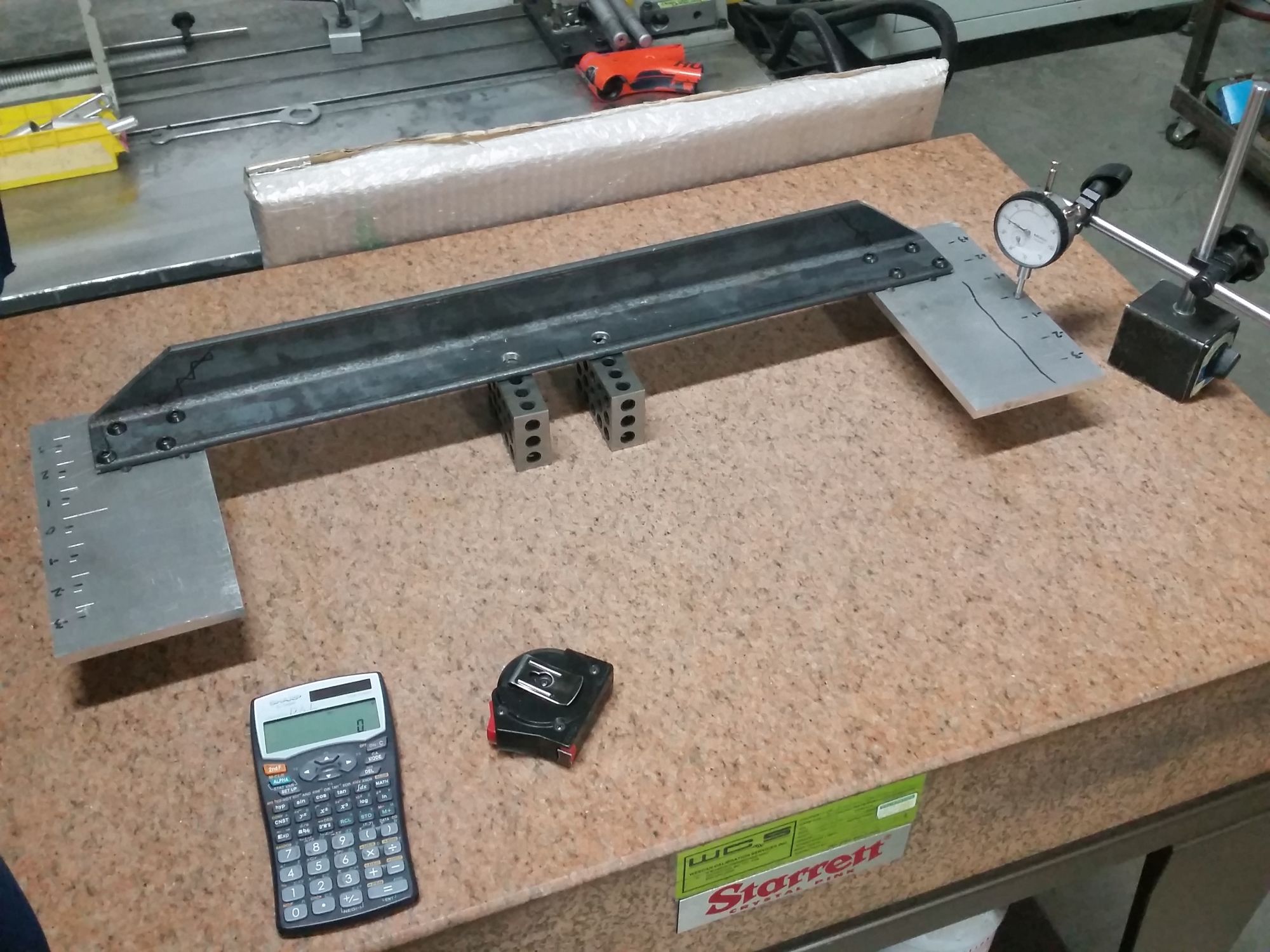
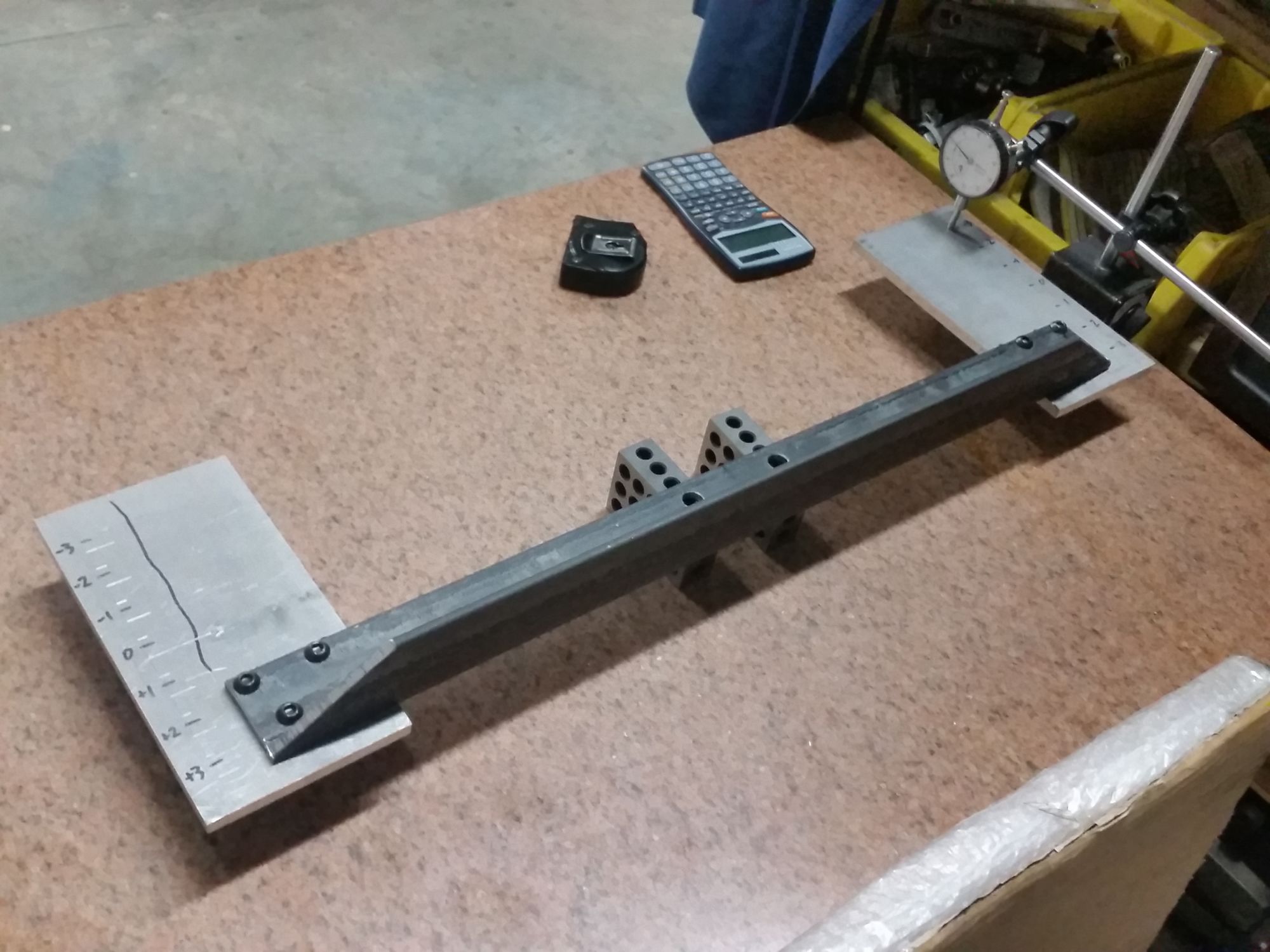
Got the bumpsteer gauge dial indicator guide plates scribed and leveled. After the cutting and drilling of everything, and bolting the two 8mm aluminum plates to the 2"x1/4" angle iron support, one plate was only out of parallel by 0.05" from +3" to -3" of wheel travel as scribed, and the other plate was 0.010" difference which I bench vise flexed back to about 0.003" total out-of-flat.. this will be more than good enough.
For supporting the two dial indicators, I found drill rod at work that I'll mount both dial indicators to, then mount to a single magnetic dial indicator stand which is stuck on a big heavy steel block as the base.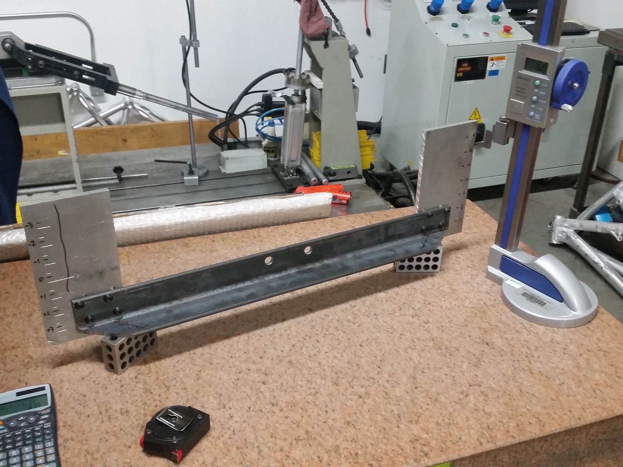
1-17-2016
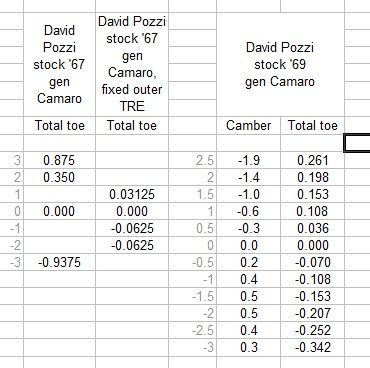
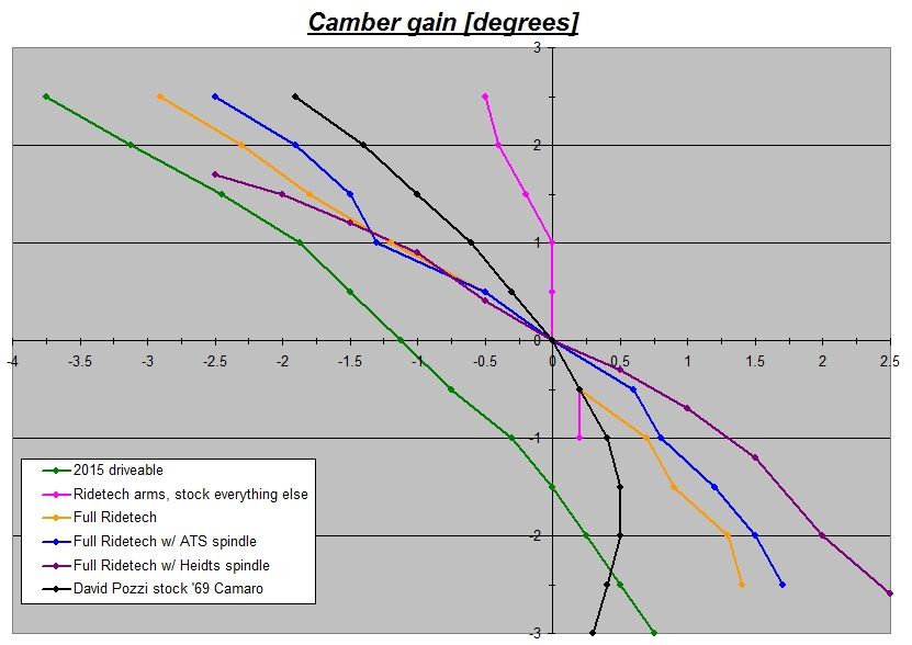
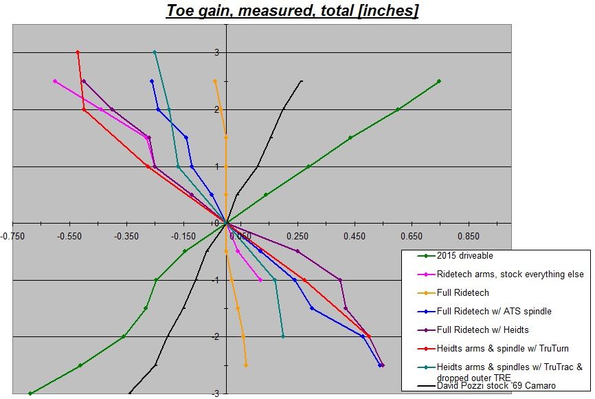
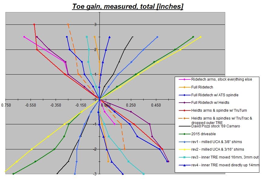
Finished the bumpsteer gauge today and gave it a whirl.. it was pretty sturdy so I'm quite confident in the measurements +/-0.005". I measured a shitload of toe out (total, not just one side) under bump... 3/4" from ride height to full 2.5" shock compression!! Even at 1/2" compression from ride height it toe'd out 0.140"! Needless to say, this will need to be addressed. I also scraped the internets for as much camber/bumpsteer data as I could find for 1st gen Camaro's. Got some good stock 1st gen Camaro data form David Pozzi's site, but I found a slew of contradictory data on Ridetech's site.. every different setup they measured toe's IN under bump and not out like what I measured as well as David's measurements of his '67 and a '69. I'll just let the graphs below speak for themselves, and some pics at the very bottom showing my bumpsteer setup at full compression, ride height, and full droop [EDIT: this must be due to where the TruTurn bolt-on drag link plate vs knuckle steering arm relocate locations end up relative to each other.. I bet the outer TRE end is moved up less than the inner TRE, resulting in a toe-in conditon as wheel travel is bumped up].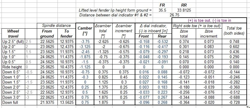

2-2-2016
No worries Jesse.. glad that the info/experience I've gained and shared can help others.
In other news, I found a video from September of a little fun...
2-3-2016
Happy to oblige, hehe. It likes to be abused..
2-13-2016
I realized that there was only so much vertical room I'd have for moving the inner tie rod end up as on the passenger side it would hit my turbo oil drain line into the oil pan, if I moved the inner TRE up the approx. 2" that the Ridetech TruTurn kit does. I also discovered that I had the manual steering slow ratio 6.0" long steering arms. Not only would using the Gbody steering arms (to copy TruTurn) require moving the inner TRE up too much, I measured the steering arms at around 5.5" long.. so I decided to search for quick ratio power steering Fbody arms. I found a set on eBay, they are 5.18" long so will give me the quickest turning, but still retain 3" drop in order to keep the amount the inner TRE has to go up to a reasonable amount. The short 5.18" length is also enough to tuck the outer TRE inside the rim hoop with about 3/8"" radial clearance
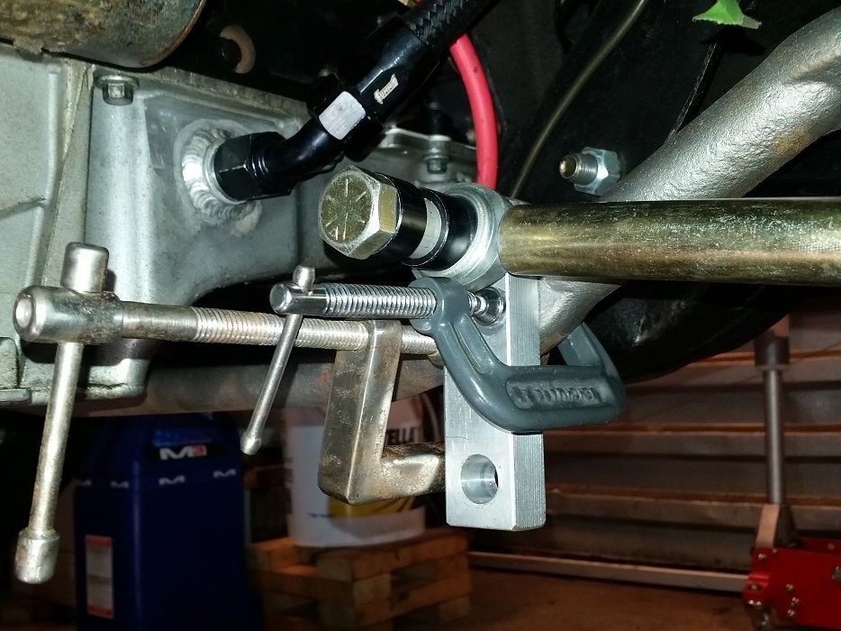
Starting fiddling with moving inner tie rod end upwards to see approx how much it would need to be raised to improve bumpsteer.. first guess was 5/8" (16mm) and it got close but overshot a bit and got toe in under compression. I then reduced the relocation to 9/16" (14mm) above stock location and got the total toe change to 0.078" total toe out under 2.5" compression.
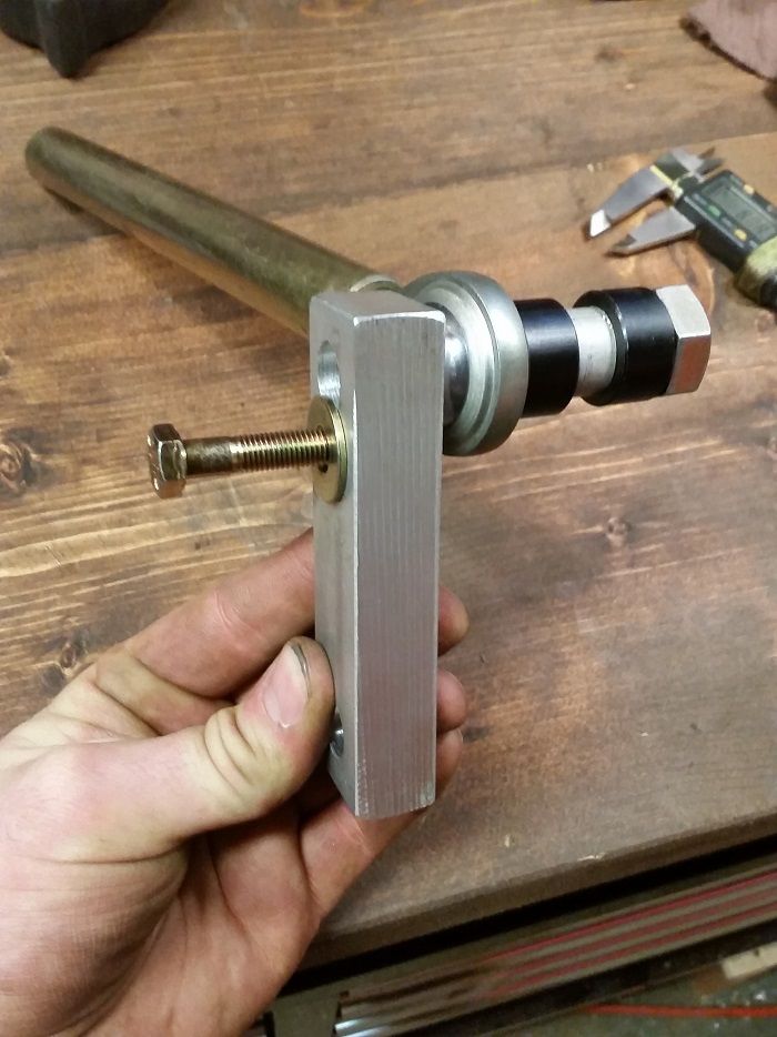
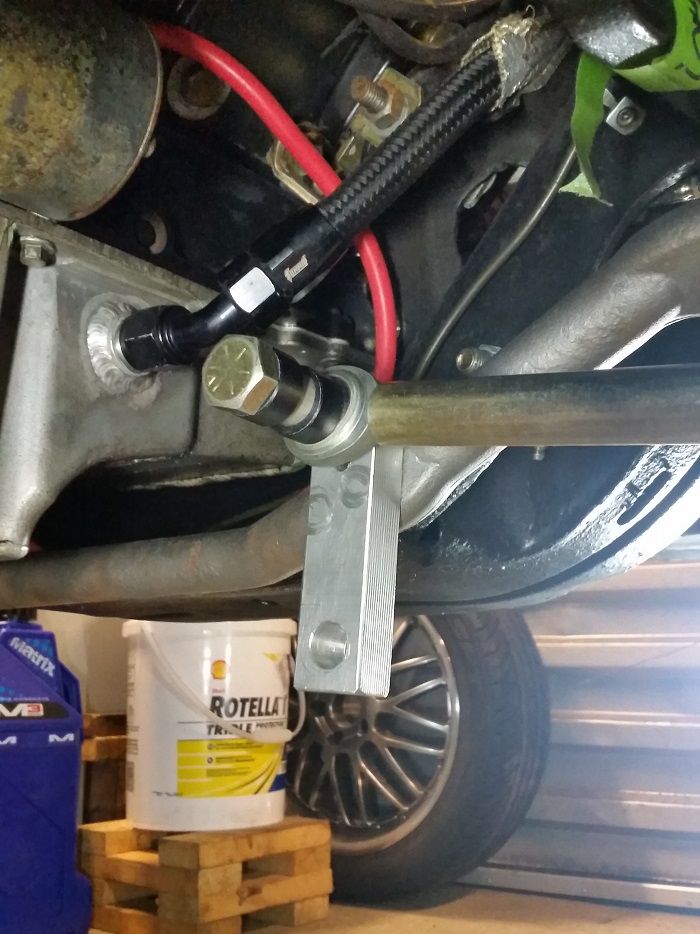
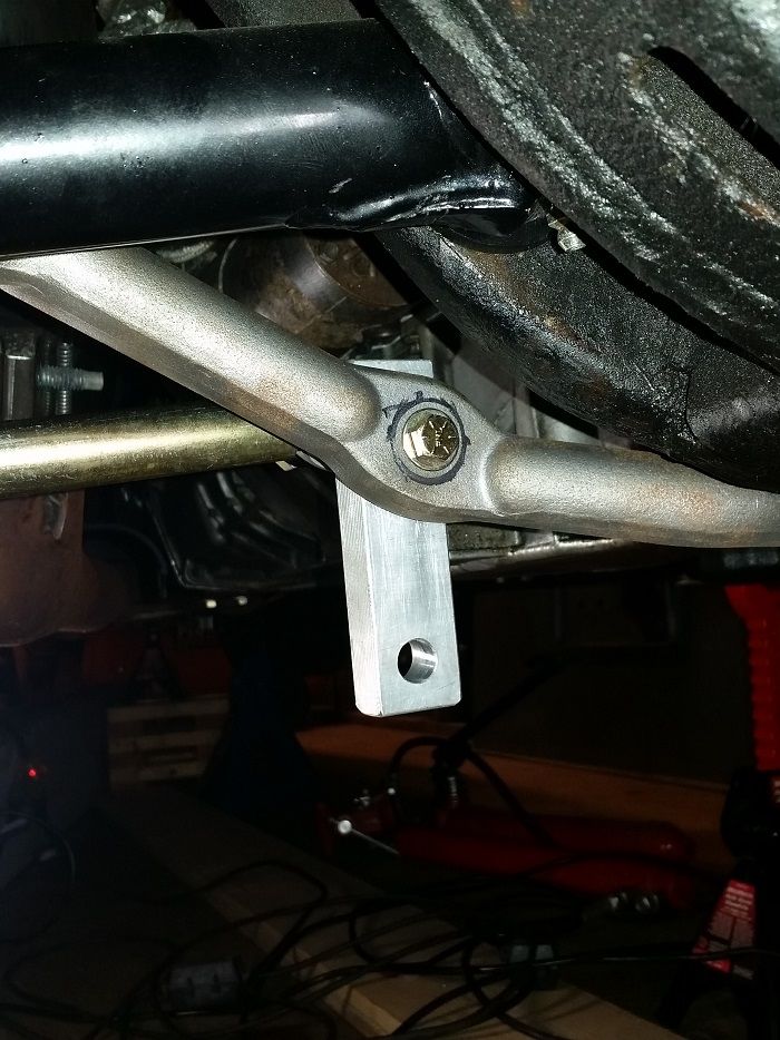
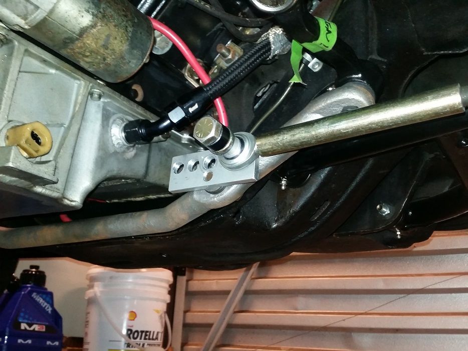
Check the pics for how I was moving the inner TRE around. 5/8" bolt thru a heim (only for experiments) into an aluminum block, then smaller 5/16" bolt that goes thru the drag link. I intentionally used a smaller bolt thru the tapered hole in the drag link to give me a couple millimeters of adjustment room for fiddling. On the other end of the aluminum block I'm going to drill the 5/16" hole at 15mm vertical offset to split the difference of the above two experiments, but also drill the hole laterally offset in the block so I can flip the block and start testing the affect of changing the length of the steering link (moving inner TRE laterally inboard and outboard).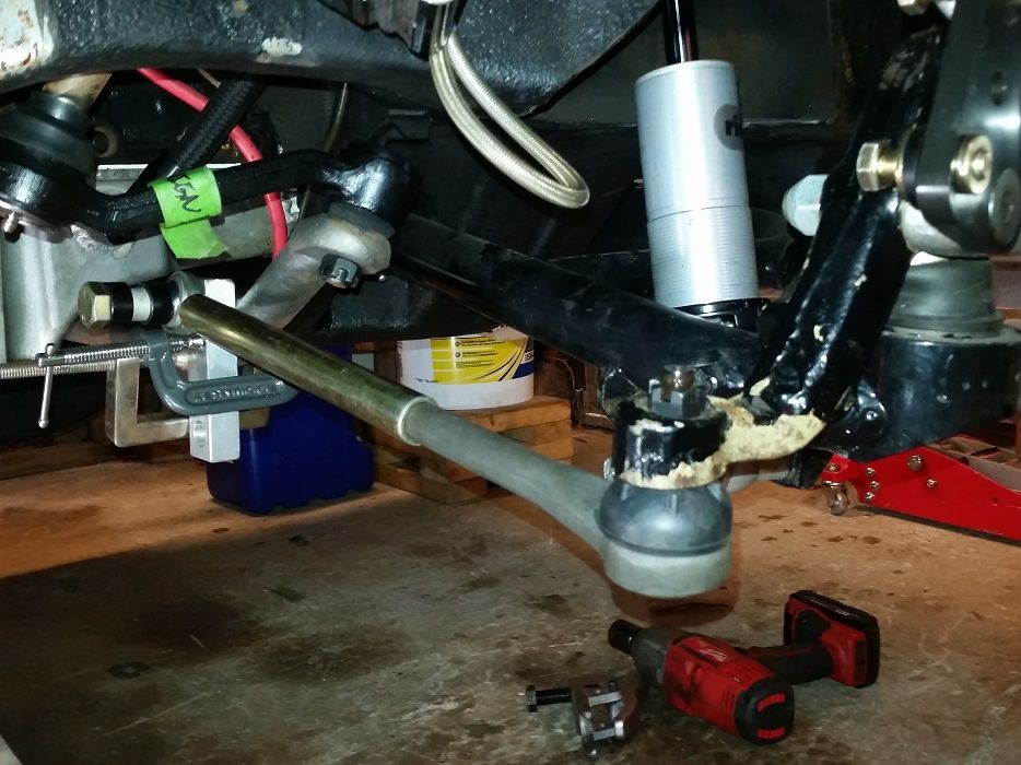
2-16-2016
Bumpsteer investigation, round 2.. for testing purposes I pegged the inner TRE raise amount at 15mm, and shifted the inner TRE inboard & outboard offset distances at 20mm and 40mm relative to factory horizontal hole location on the drag link.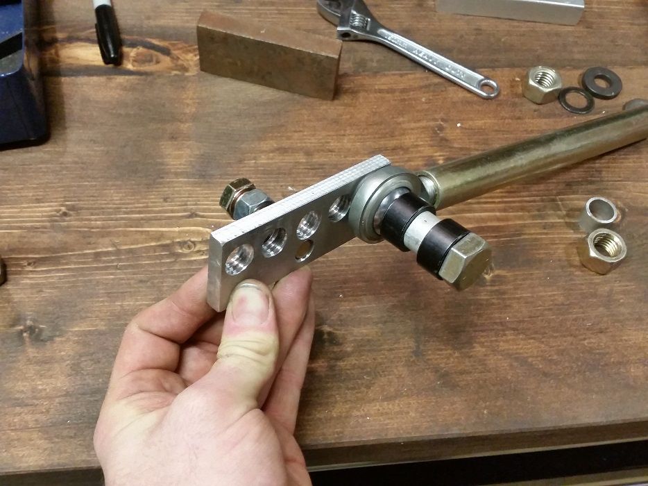
Interestingly, moving the inner TRE inboard 40mm makes the curve almost linear, meaning I've almost matched the sweeping arc of the steering link compared to the virtual pivot point of the UCA/LCA linkage, over the 5" travel range. Now that the path of the steering arm is more consistant due to a matched arc of the steering arm, in order to minimize the steering input that near-linear line needs to be brought as close to vertical as possible, so I'll try lowering the inner TRE from 15mm raised height and see what happens.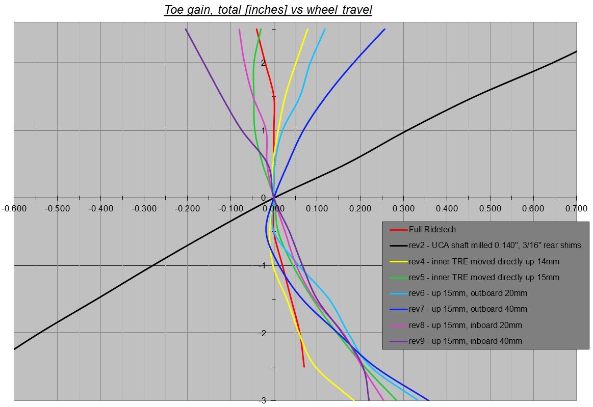
2-18-2016
You're correct.. y-axis is suspension bump (positive) or droop (negative).. just because that's how my brain works. Toe (measured total, AKA the bumpsteer measurement doubled) is positive as the car toes out, and negative as car toes in. Camber is self explanatory for positive & negative.
Very true, traditionally the 1st gen suspension should camber positive in stock form under bump, however according to Ridetech's website, a stock suspension with only Ridetech arms will camber negatively (even though only slightly) under bump. However this could be with lowering springs to slam the front end enough such that at the starting ride height, the control arm geometry has already crested over the positive camber point and will start to negative camber under bump.
http://www.ridetech.com/store/tru-turn/
For Pozzi's measurements.. good catch. I went back and re-checked and looks like I copied the values reversed. I can't seem to find the actual text list of camber/travel numbers that I copy-pasted into Excel, however he clearly explains on his page that up/positive is droop and down/negative is bump... however he still lists negative camber gain under bump. The starting point (ride height) appears to be very important for camber gain, especially with taller spindles or Gulstrand mod as those affect the "sensitivity" of camber gain from said ride height starting point.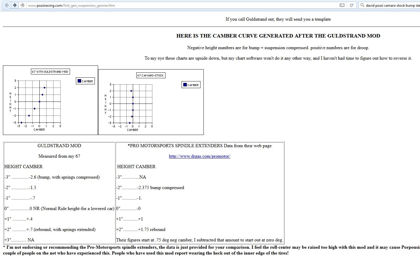
For mine, I have done the Gulstrand mod, as well as mine being super low, so my instant center is quite lower on the car making it negative camber pretty aggressively with not too much bump.
3-5-2016
Did some more on the steering today. In my last update post I stated that I had found a new lateral location for the inner tie rod end, to make the bumpsteer curve pretty damn linear. So I continued on that today with finding a new height at the more-inboard location, to get a linear and vertical bumpersteer curve. I kinda lucked out and randomly moved the tie rod end down 1/8" and got it right the first try.
Below is the bumpsteer curve for rev10.. one line shows it at 0* steering angle, and another shows it at 10* steering angle. So when the car dives at 10* steering angle, the front tires toe in, and when the car lifts, the tires toe out. This required me to take bumpsteer measurements with reference wheel (passenger side for my measuring setup) turned 10* outboard, then again at 10* inboard, and use the addition of the two for calculating travel bumpsteer when the wheels are turned. This is assuming no body roll, which of course is not exactly accurate to real life even with the stiffest front sway bar..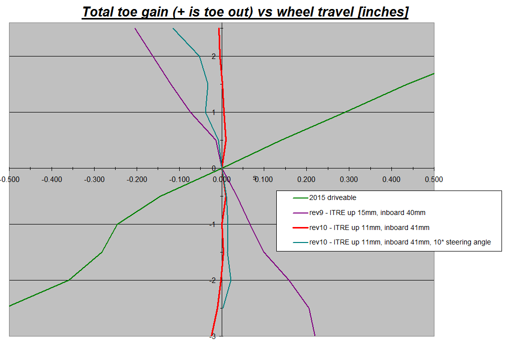
Because the body rolls during cornering, I also calculated the toe-out curve for 10* steering angle, as the body rolls thru the wheel travel..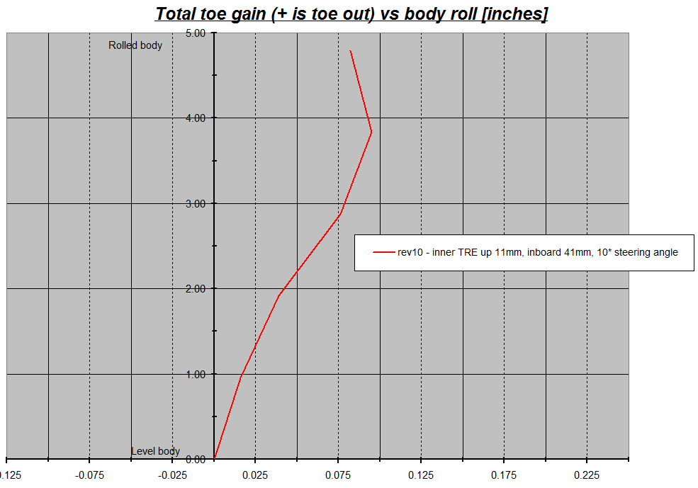
Using the toe-vs-travel, and toe-vs-roll, I could technically figure out what the bumpsteer/toe gain could be for a particular cornering situation of say 1.5* body roll and 0.5-1" dive from braking, blah blah blah, but that isn't necessary now and the beer is making me not care as much.
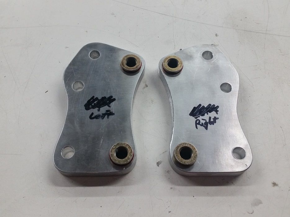
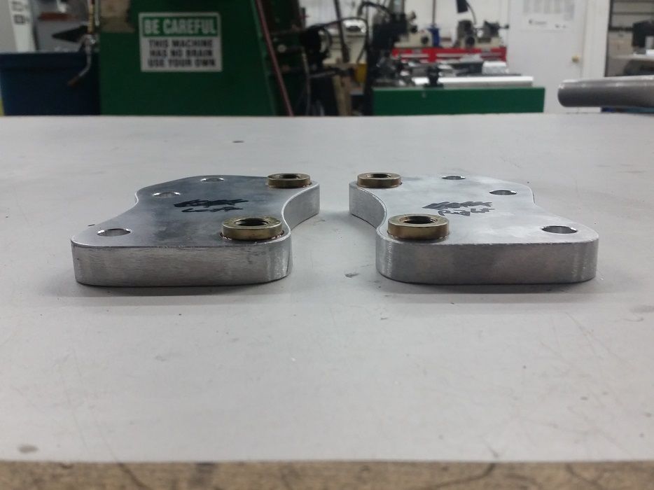
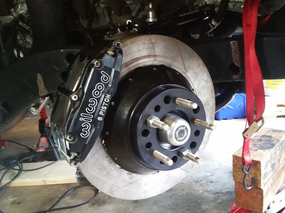
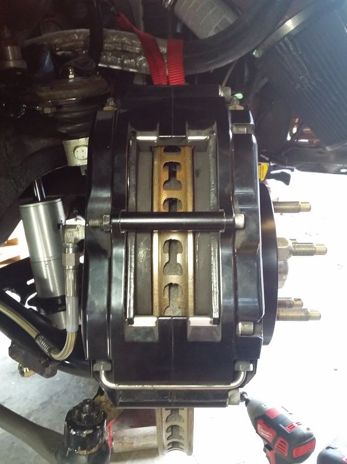
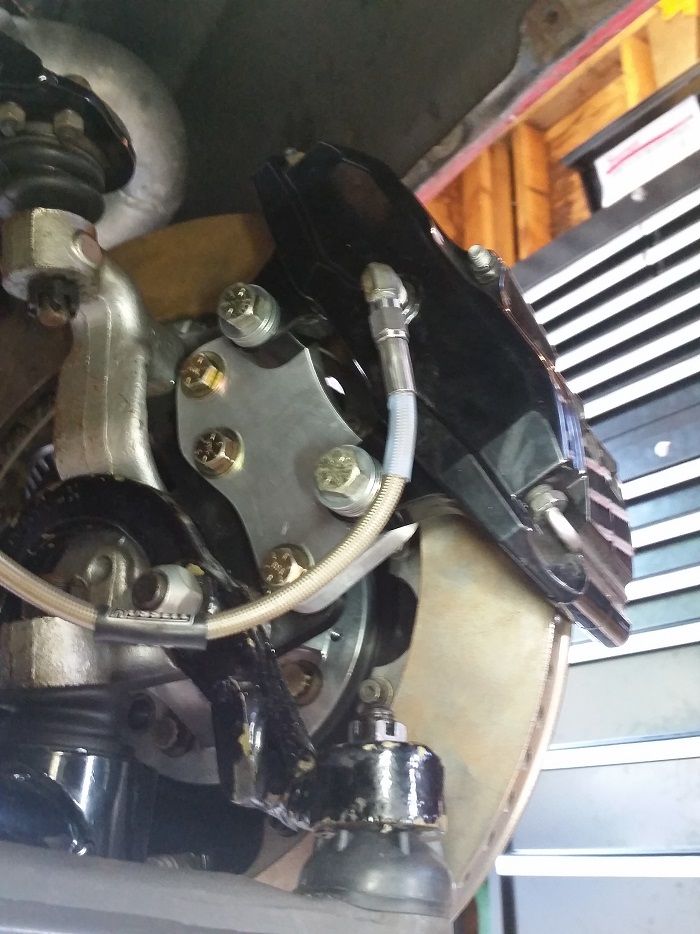
I also got the new caliper brackets made to fit the lug-mount Wilwood Superlite 6 piston calipers onto the larger 14" rotors. You may as "why the f*** would he make brackets and not buy them?".. well the 14" rotor version of my kit was only ever offered as a radial-mount setup for a 14" rotor, even tho the caliper looks otherwise identical to mine. So since I couldn't use the official Wilwood 14" brackets without getting new calipers as well, I made.
Some stats: Previous Wilwood 13" brackets were 3/8" thick, mine are 1/2" thick. Previous had significant profile cutting, mine have more beef and less weight-saving cutting. Previous were surprisingly made of 6061-T6 aluminum (don't believe the "aerospace spec technology".. this stuff is as standard as it gets and not the strongest around) at ~45,000psi ultimate strength. Mild steel is ~63,000psi ultimate tensile strength. I made my brackets out of 7075-T651 aluminum.. 83,000psi ultimate tensile strength! Enough blabbing...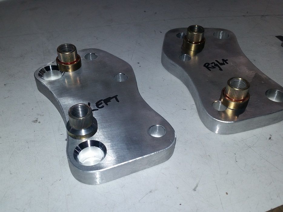
4-14-2016
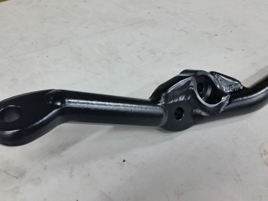
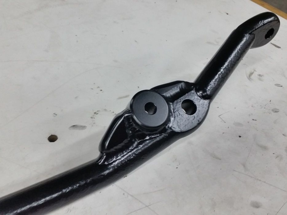
Got around to modifying the center link for new optimized inner tie rod end positions. I 3D modelled several different designs but ultimately came up with turned location slugs partially recessed into a notched center link, with gusseting for over-building the strength.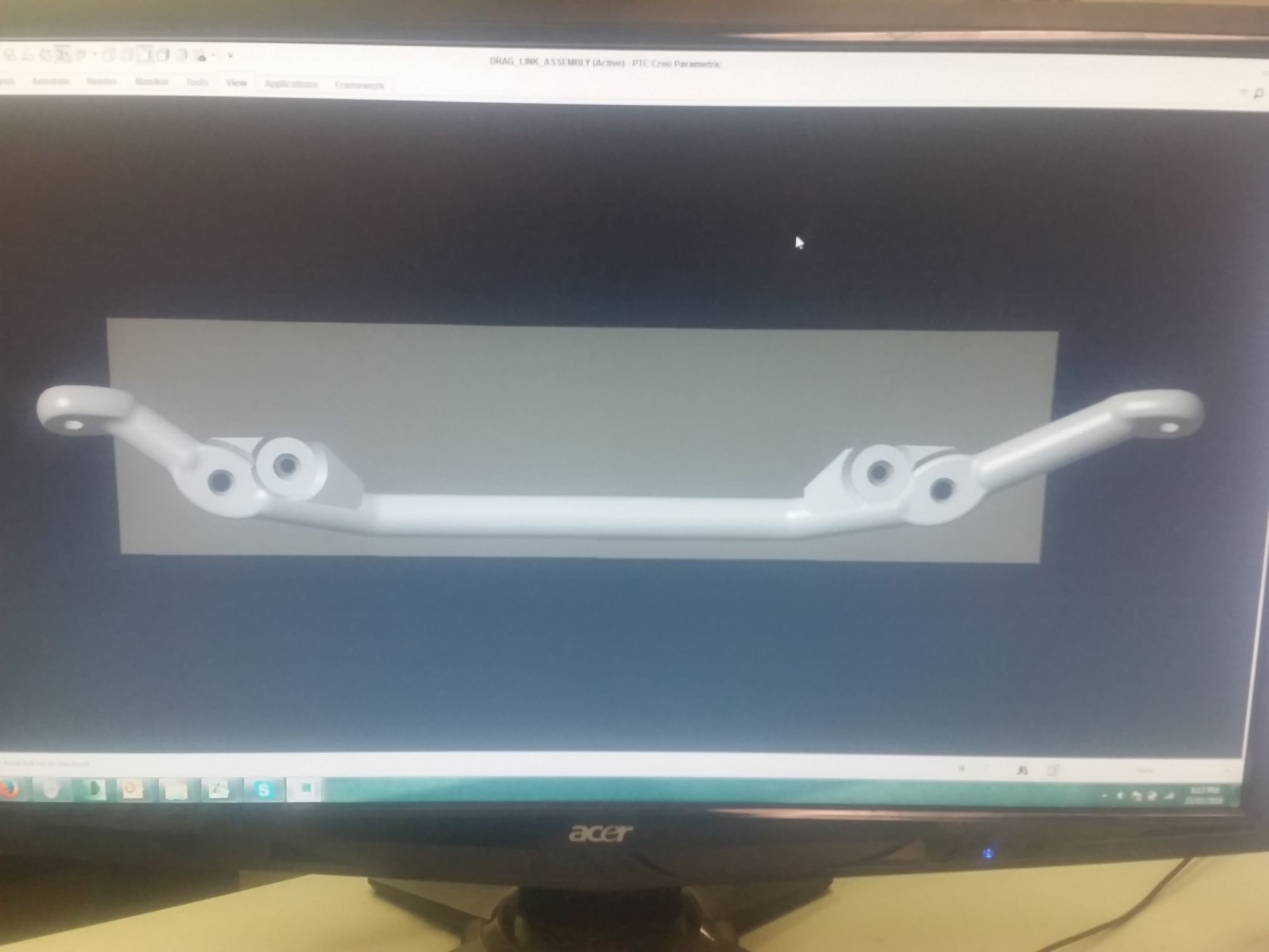
Started with clearance cutting the center link..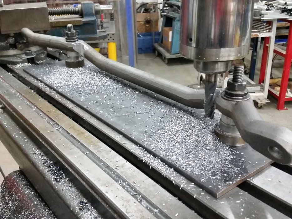
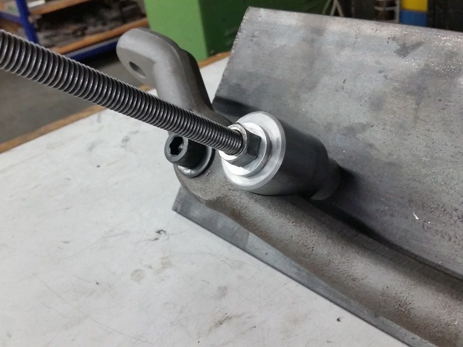
Then used an adjustable boring bar to bring the notch diameter up to the OD of the slugs for the new inner tie rod end tapered holes…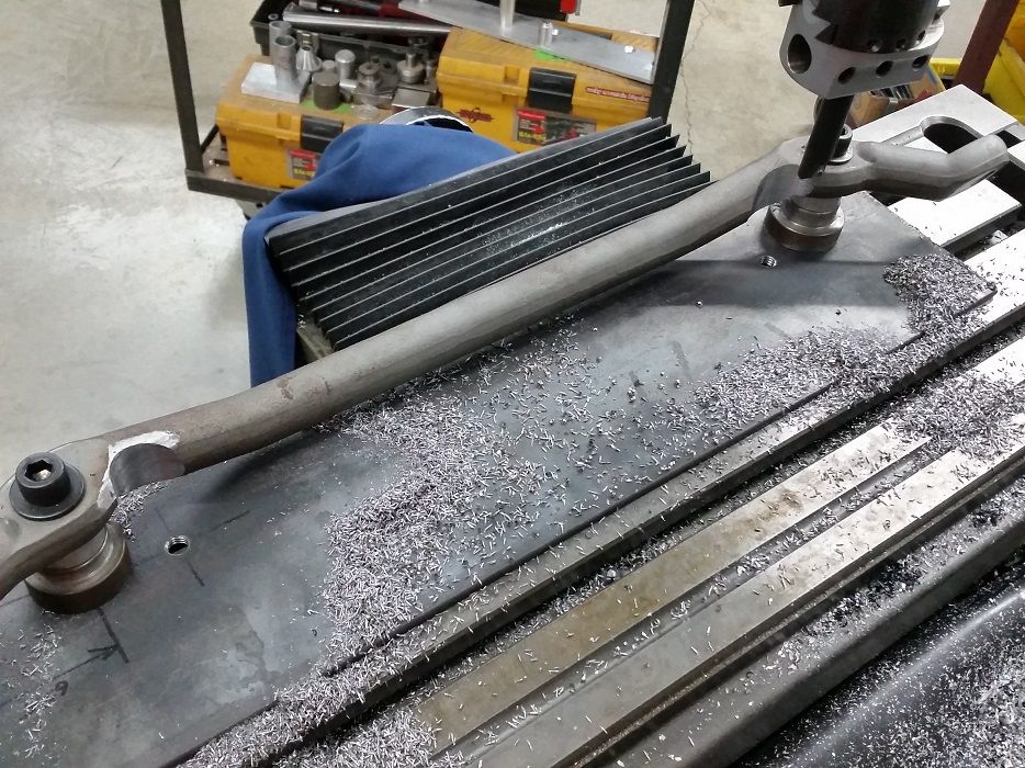
Of course the proper way to do all of this for fitment checking as well as welding is to have a jig to hold it all together…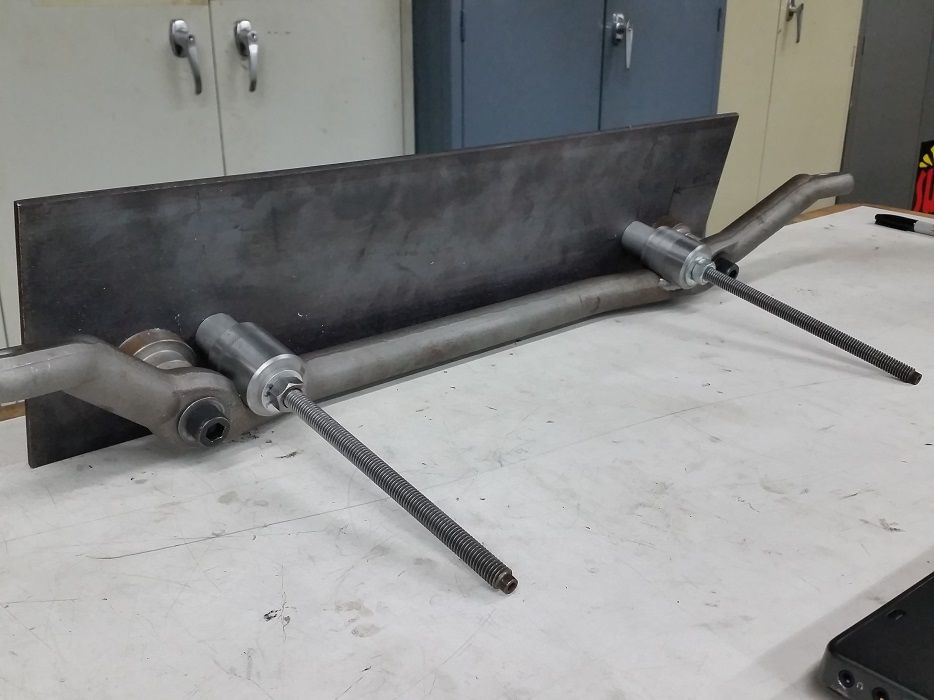
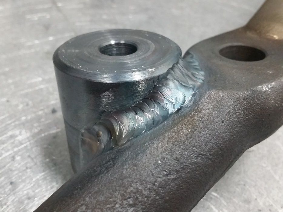
Did 3 passes of the slugs themselves (center link was heavily chamfered previous to welding, to ensure good penetration…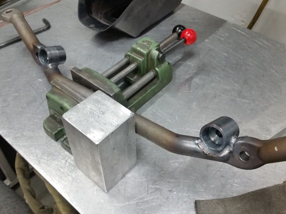
Then cut out and added gussets for even more strength…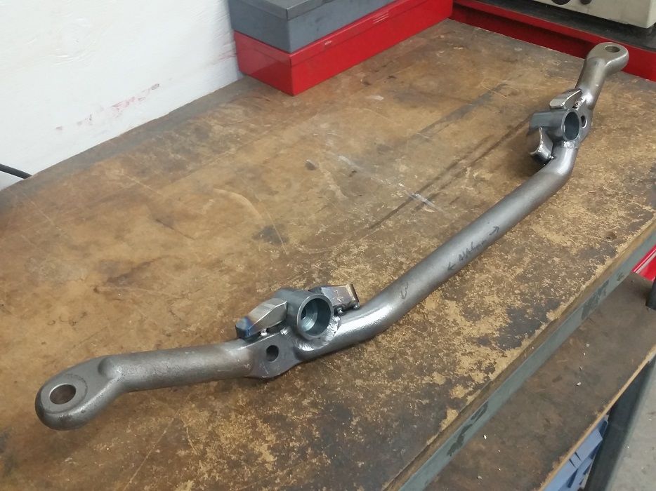
First weld pass on gussets…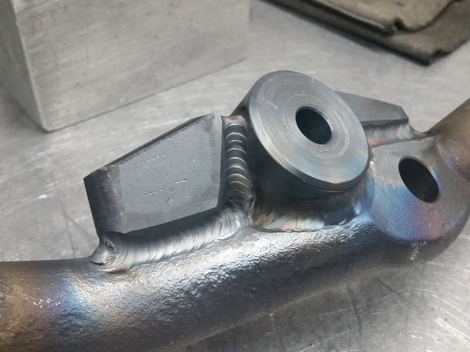
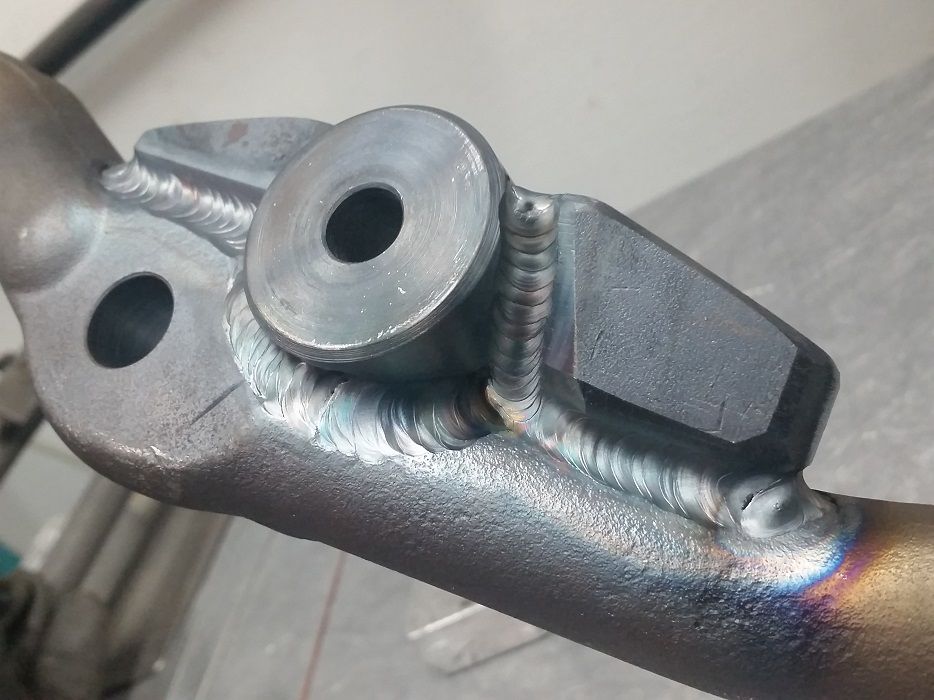
The final (4th or 5th pass, can’t remember) weld pass…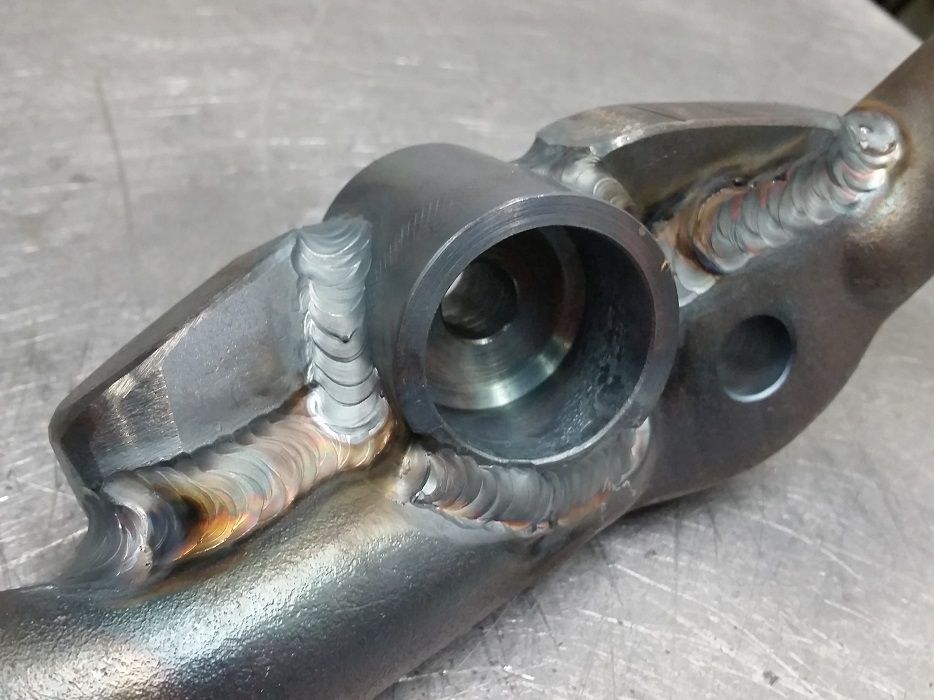
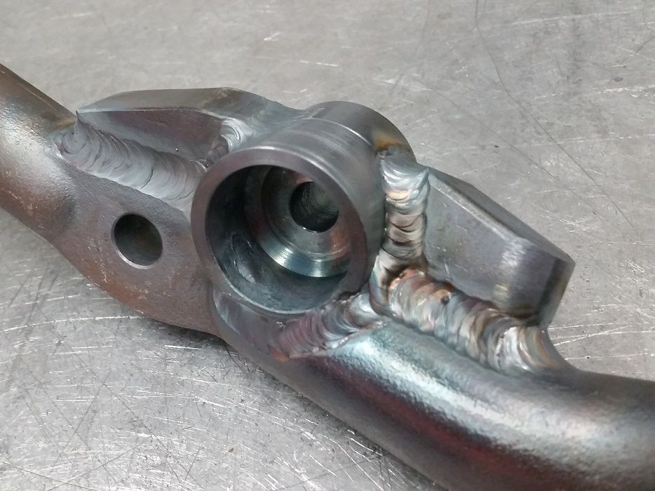
Ground the gussets down a bit to streamline them and painted. Still need to ream the tapers into the new locations and clean up the tapers on the existing holes for pitman and idler arms..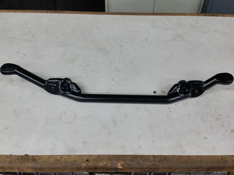
5-9-2016
Got the car back together and insured!
Started with reaming out the holes in the slugs that I welded to the center link..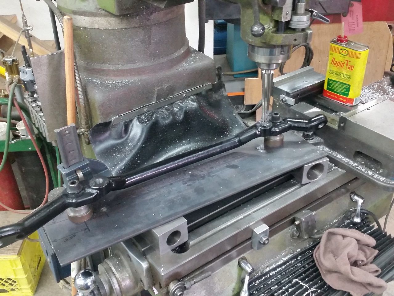
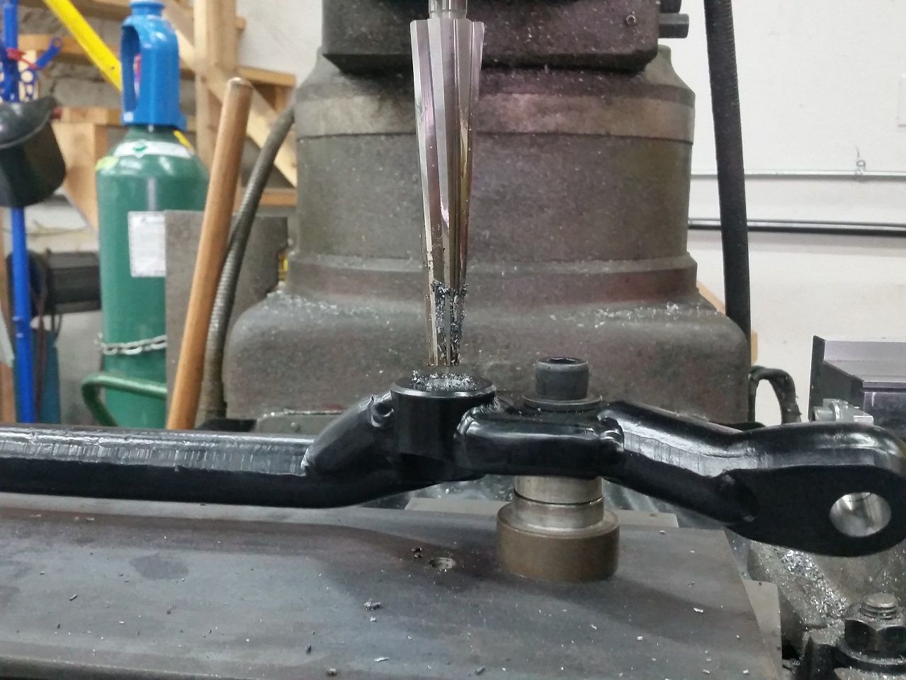
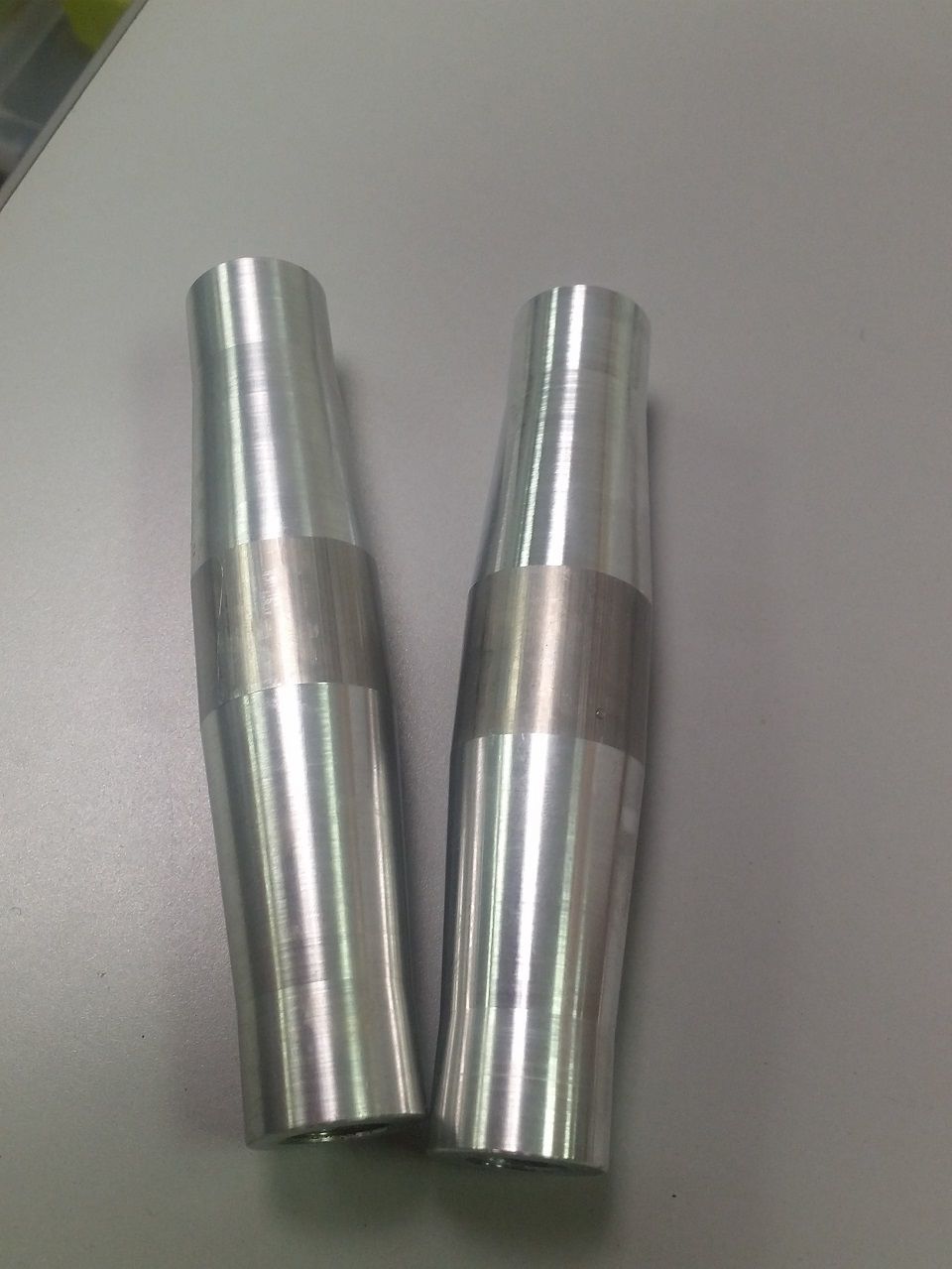
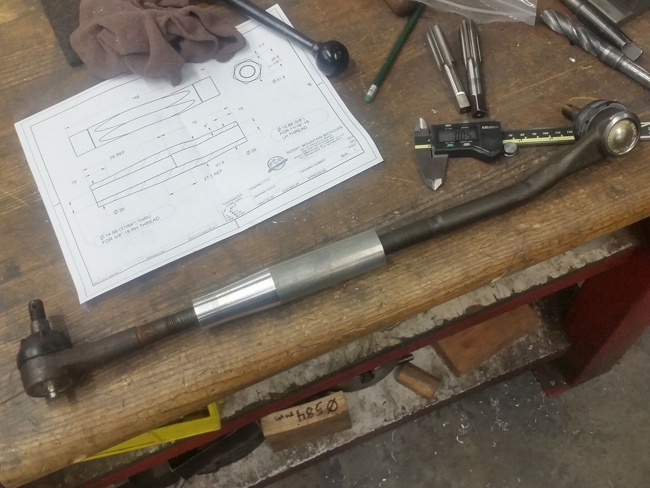
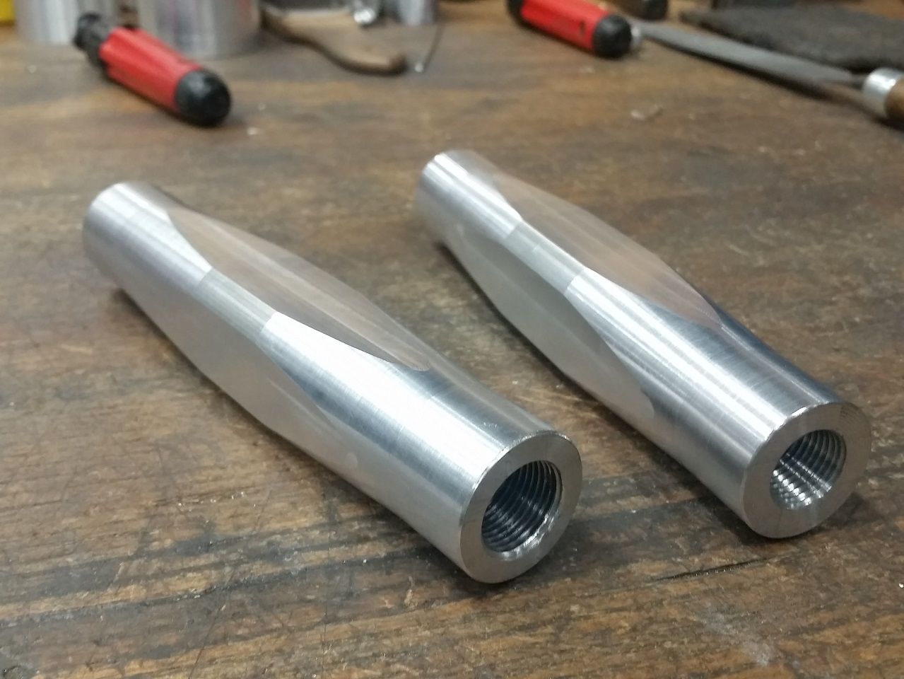
I ended up using longer inner tie rod ends from I believe a '73-'79 X-body application (GM obviously did a similar fix as I did by moving the inner TRE locations inboard after my model year!), and because I couldn't find a long enough length outer TRE in 11/16" thread, I ended up re-using my tight existing 5/8" outer TRE's. This meant I had to make some tie rod end connecting sleeves..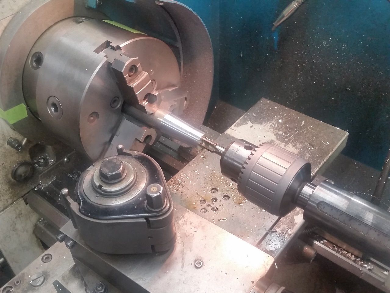
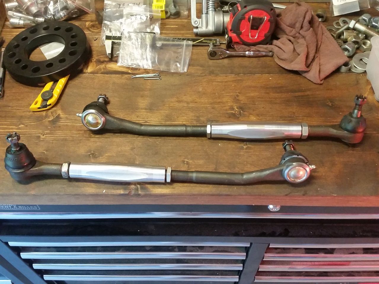
After the first test rip last night.. **** it real good. The steering is firmer but quicker since swapping to the fast ratio steering arms and pitman/idler arm. Turn in is super quick but doesn't have that crisp biting edge.. mainly because I still haven't made a front sway bar yet! That'll be a future update. Going around sharper corners with bumps at speed is super sweet now.. steering is completely neutral with no weirdness! I'm stoked.
5-20-2016
Haha thanks, it was a lot of work but I feel it was totally worth it. Now that the steering feels much more responsive, I was going to double-check my toe, then lift it up and put on caster dollies at which point I could take some measurements.. I want to measure what the Ackerman is like since I've moved the middle of the inner tie rod end ball back about 3/4". I can measure the bumpsteer when I take the LCA's off to weld on sway bar tabs later in the summer, since it'll be easiest to remove the coilovers with the LCA's off.
Edit: since the UCA's, LCA's and spindles are all using stock locations which I am not into modifying/changing, the only way that this new optimized bumpsteer geometry (centerlink) becomes obsolete is if I really jack the front of the car up.. but since it looks so sweet at this low ride height, and now has good camber gain and steering.. why would I do that!?
I'm going to do some experiments with moving my wheels outboard with thicker slip-on spacers to increase scrub radius, as my return-to-center still isn't what I'd like it to be. The trail of the wheels should be good enough to make them return decently since I settled on 6.25" of caster. The SteeringAxis Inclination (SAI or Kingpin Angle) on these stock spindles is supposedly 8.75*, which should in theory be enough to create good return-to-center. I'm thinking the scrub radius got a lot smaller since widening the front rims entirely inboard 1.5", possibly counteracting some of the return-to-center action and steering wheel feel I gained by going to the correct quick ratio steering/pitman/idler arms. It is also possible the the T bar in my steering box is pretty weak allowing lots of power assist as it's very manageable to turn the 275's while stopped on pavement.. not pink-finger-turning like a Cadillac, but not as much resistance as I'd hoped. I don't think there's any way of confirming what assist level box I have since I can't find any stampings/markings beyond the fact that it is indeed a 12.7:1 quick ratio with metric o-ring fittings.
Going off on a tangent here but below is a good link I found for steering box information on these old cars...
http://www.pro-touring.com/threads/4...Fast-ratio-box
5-25-2016
I drive the car into work or elsewhere every 2nd or 3rd day.. I split commuting between the car, my silly Cummins 2nd gen and actually cycling a bike into work. After thrashing to get my car together on a Sunday a couple weeks back I daily drove it for 9 days in a row.. the most consecutive since I used to occasionally commute it to BCIT. The girlfriend really enjoys me scaring her friends in it though.. hehe.
As for speedo.. I need to take the dash out to rewire the signal wire from the Holley ECU since I found out too late it needs a specific plug on a separate I/O terminal other than what comes on the basic main power harness. Also need to figure out how to wire the wideband Speedhut gauge to some Holley output. And add in key-on wiring for a future transmission pump. And while I'm at it I think I'm gonna remove the heater core to save some weight and free up room in the engine bay for next winter's "refresh". Oh and need to figure out if my intermittent headlight power is from the dash switch, highbeam switch, or funky original wiring/fuseblock.
Long story short, I've memorized that 4th gear 1500rpm or 5th gear 1100rpm is 50km/hr, and 5th around 1400/1500rpm is something like 80km/h. I also just got in the mail a suction cup phone holder and I have a GPS app I like, so I might keep tabs on things like that for the time being..


Wow thanks for sharing!
Posted by Diggymart on 3/3/19 @ 12:40:25 AM