You must be logged in to rate content!
121 minute(s) of a 891 minute read
11-23-2009
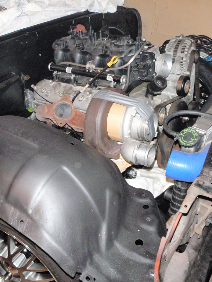
A slight amount of progress... picked up a set of Corvette manifolds, not sure if they're LS1 or LS2 but they should work out better than the tubular shorties I previously mocked up...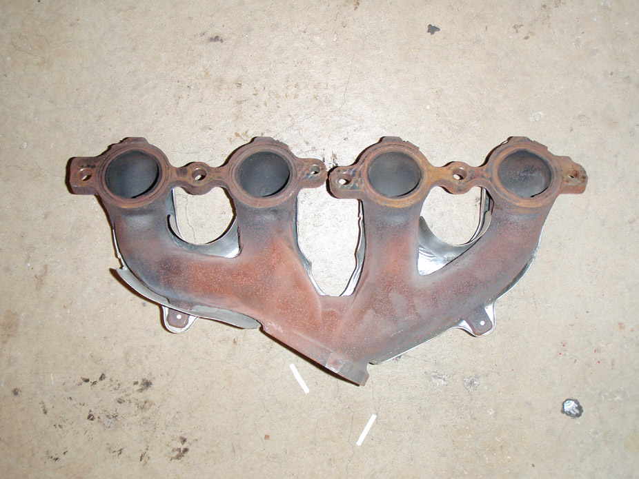
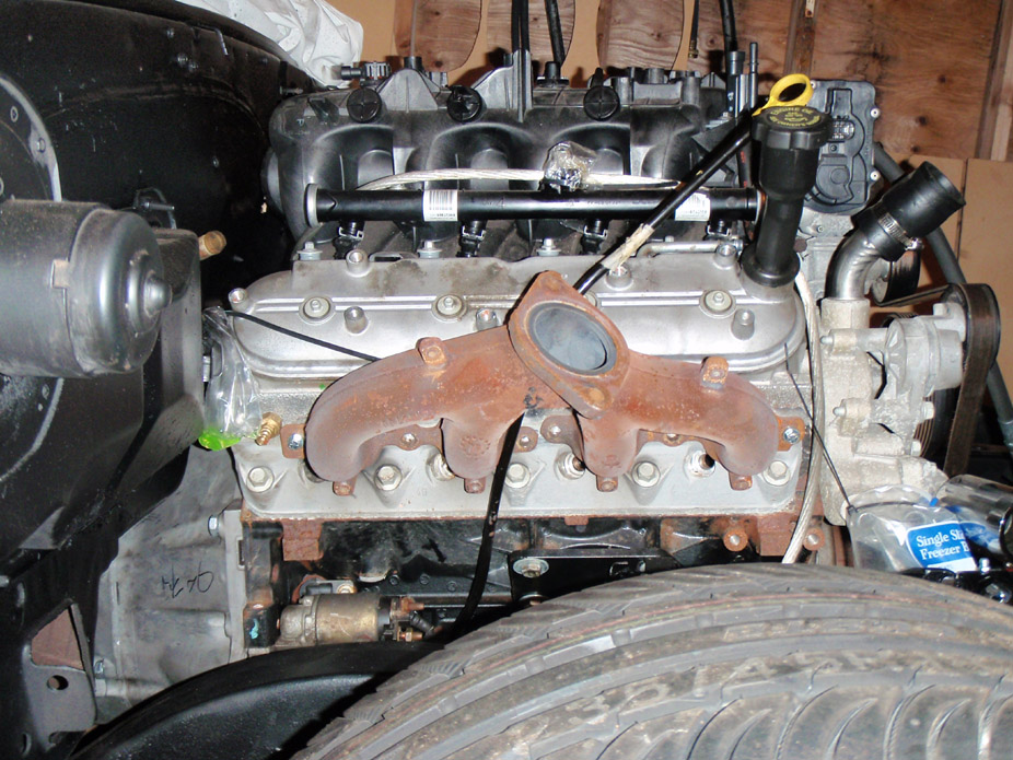
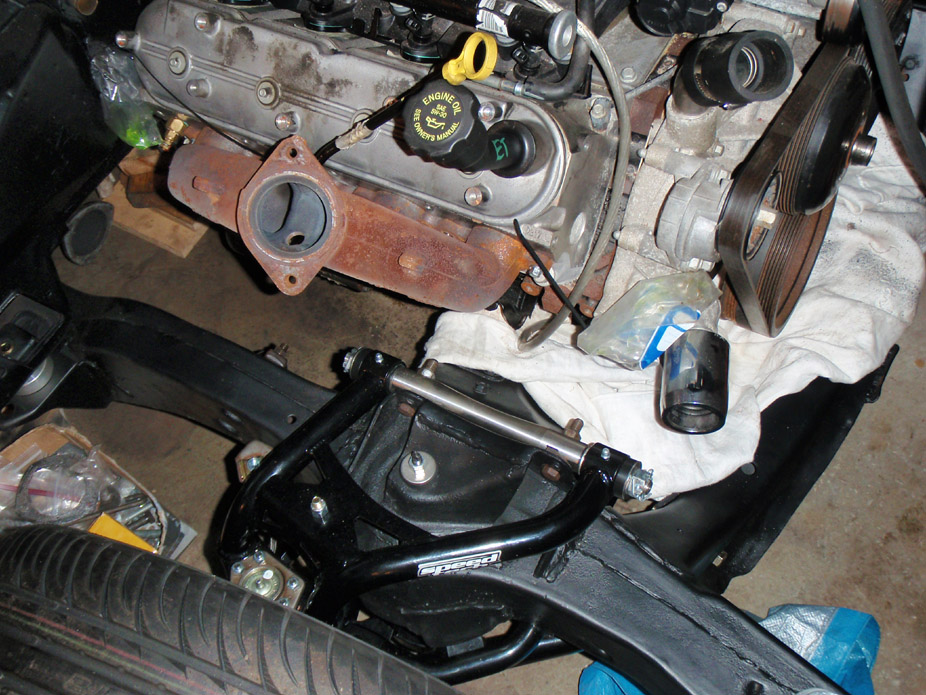
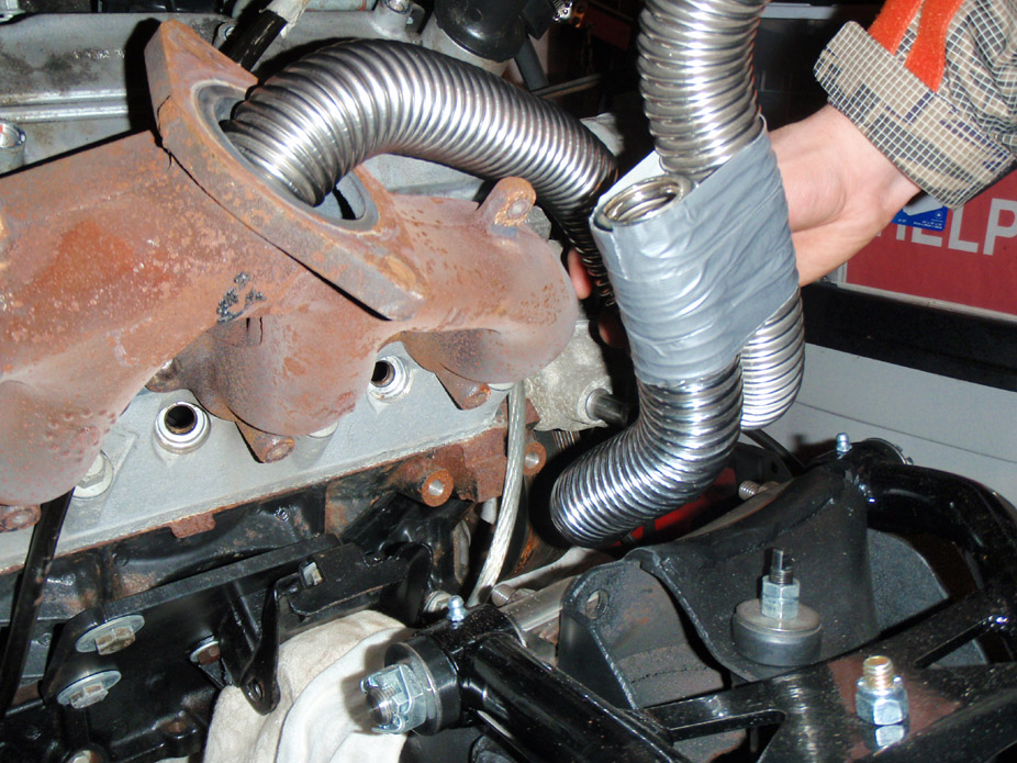
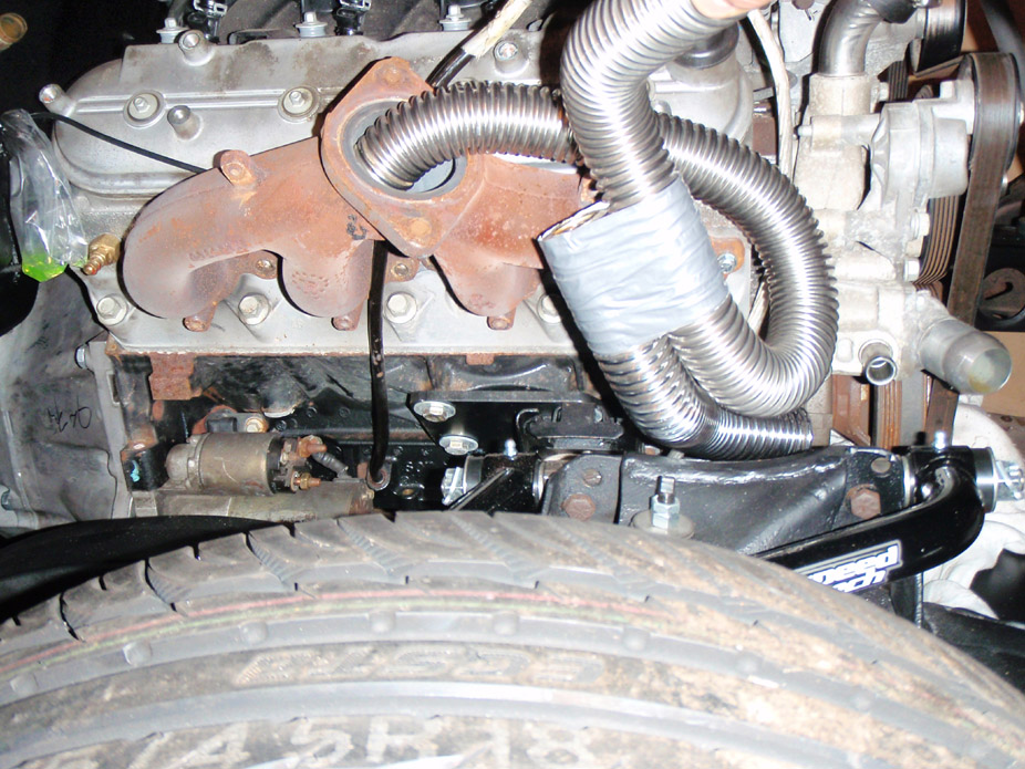
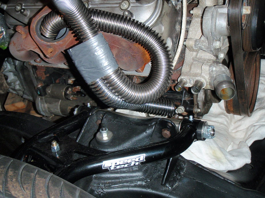
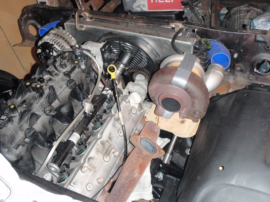
Those UGLY cookie-cutter parts-book street rod cheesy radiator hoses came into use!! The duct tape is approx. where I want them to merge. That merge point is currently pretty close to the valve cover & makes the passenger side pipe have a tight-radius bend, I'll likely move it out more sideways & over the inner fender allowing that bend to be larger/smoother. But they do show how I want the passenger side pipe to wrap tightly wrap around front of the manifold then scoop back and sideways.
The crossover pipe should be able to fit between the block & subframe cross-member/control arm cross-shaft, behind the waterpump outlets. Marktainiumsuggested plugging & tapping hose outlets below or above for more crossover pipe clearance...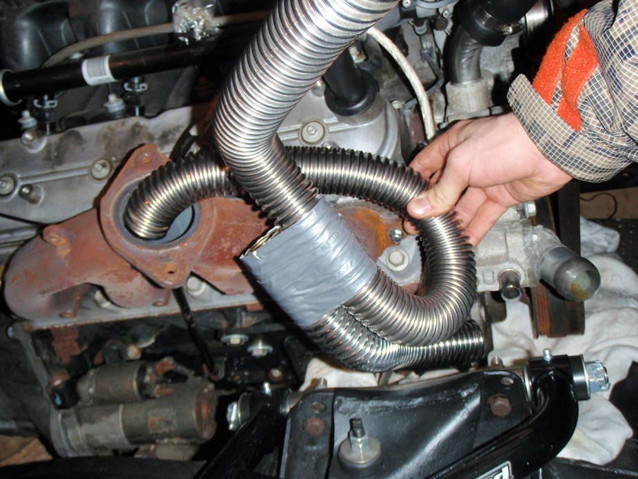
Garage is too small!!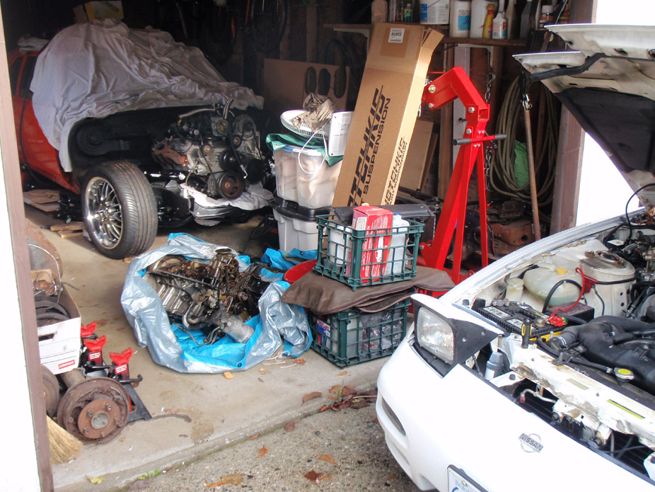
My other ride/daily driver...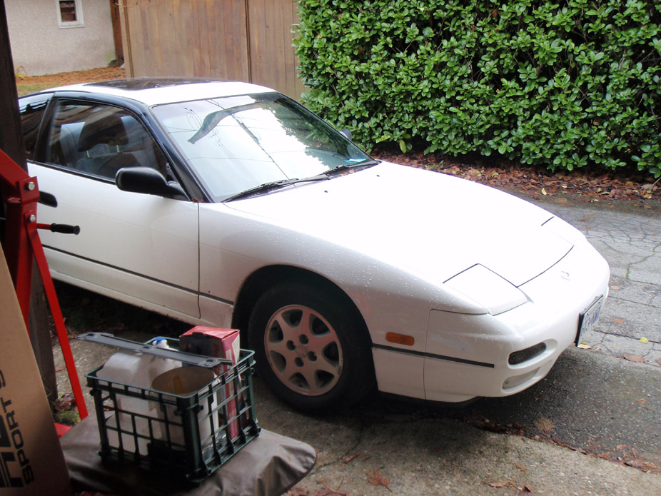
1-8-2010
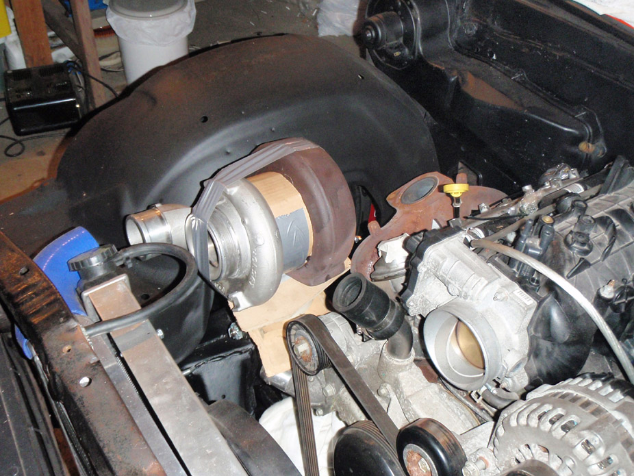
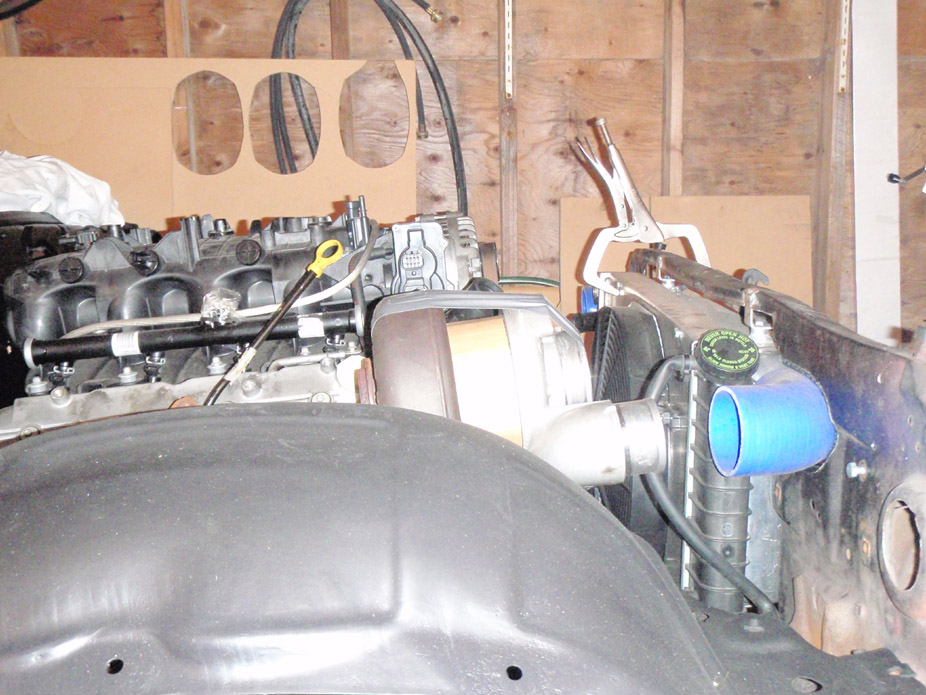
I'm back for 4 months in the same town as my car so time to get back at 'er. I've been lazy recently & over xmas break, so I just started mocking things up (barely) to have something to look at. The pictures are deceiving... DAMN this turbo's exhausthousing is huge, gonna have to re-think how to route the passenger side exhaust, but I think I can still raise the thing up another 2-3".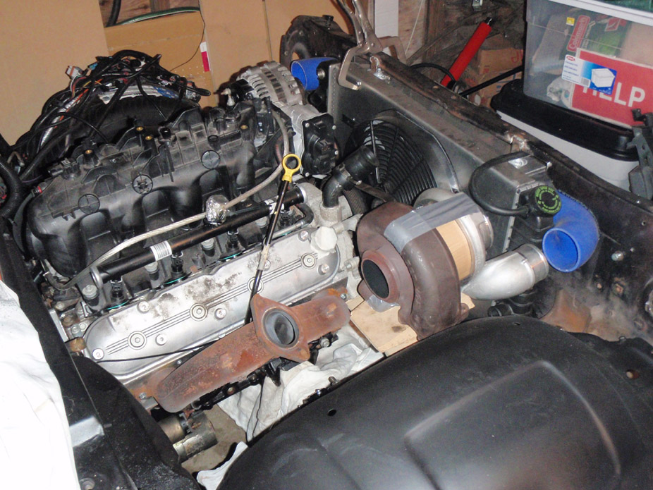
1-21-2010
I've realized I hop around too much between side-projects for this car. I need to choose a place to start and systematically finish ****, so I need to finalize the trans height before I can start mock-up assembling front sheetmetal for turbo plumbing fabrication. So I don't burn out, I'm doing stuff in small but steady amounts, a couple hours a night. Tonight was to start making room for the shifter...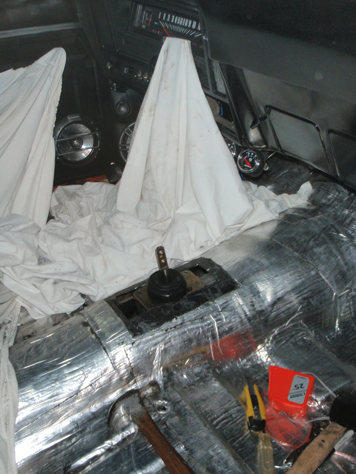
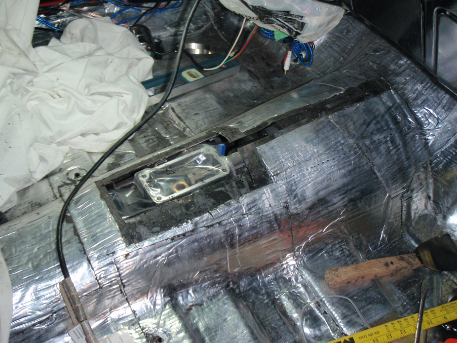
This pic shows the idea better, chop out room for the shifter assembly (and make a cover-panel), but split/pry the tunnel apart forward of that until there is enough clearance, then just weld a filler strip in the middle...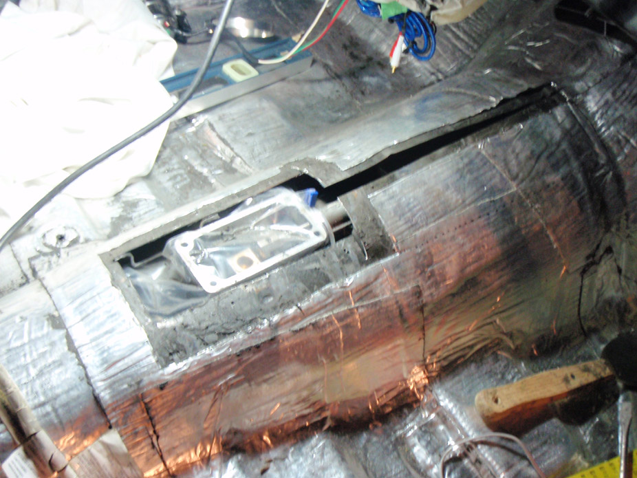
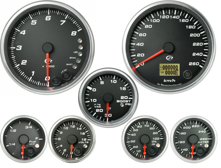
After a couple weeks of chipping away at stuff, I plan to have the trans tunnel & trans cross-member complete, and start hanging front sheetmetal and get deep into the turbo hotside fabrication... then I'll order these gauges as a reward for my progress ...
...
-ALL gauges are 1.1" deep
-come with wiring pigtail & 8ft of harness
-all are electric (stepper motor) and include sensors
-all are full sweep
-classy and simple/understated yet modern look
-you can customize the face color/daytime letter color/reverse-glow bulb color as well as the font, font size, needle spin direction (some models), needle daytime color, needle glow color, and the bezel style/color/finish!
-they're NOT run-of-the-mill Autometers
http://www.speedhut.com/gauge_produc...uto=revolution
Did a quick sketch of what I'm thinking for a removable shifter access panel...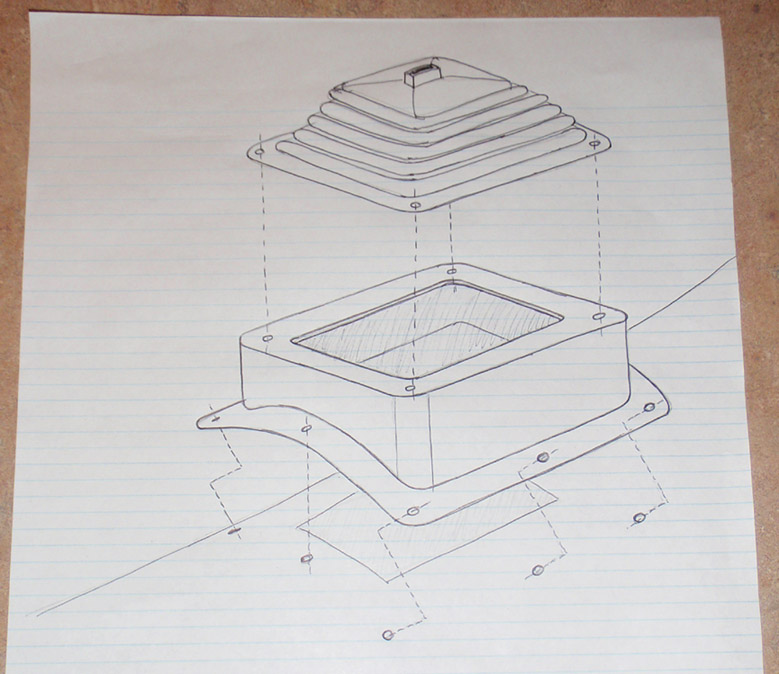
1-30-2010
I've had to do more "clearancing" to make this huge trans fit. Apparently Nova's have pretty shallow trans tunnels. This pic is with the T56 at 2* which would be the highest I'd ever run it, and the height for which I'll make new tunnel patch panels accommodate. I plan on making the trans cross-member very adjustable, to lower the trans to 3.5* if I ever wished to do so...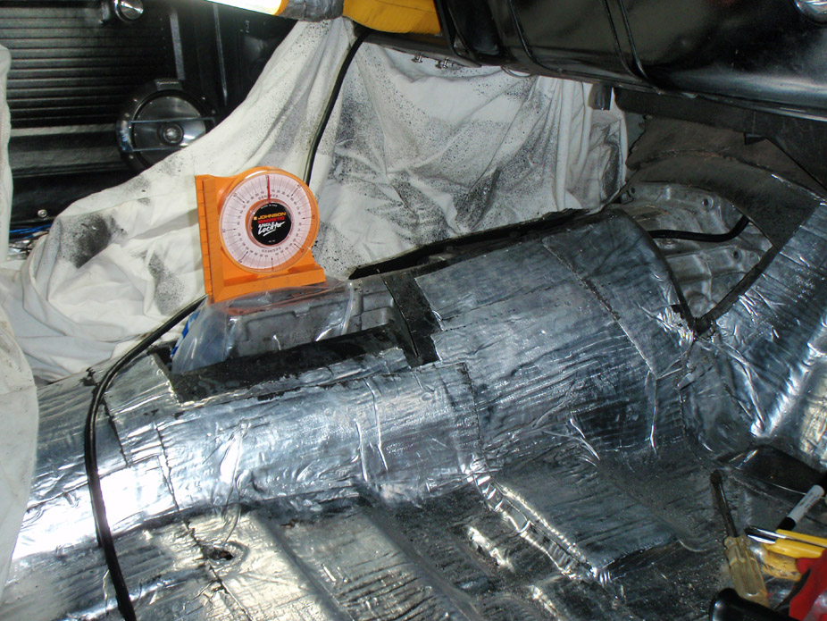
The last couple nights I've been working the x-member, and I've got one side finished so far. A big pet peeve of mine is cars that have exhaust hanging way low... especially due to off-the-shelf headers with retardedly low collectors. So I've gone on a clearance mission... I plan on having the subframe rails the lowest part on the car (including exhaust/trans/oilpan). I plan on making both sides look like this incase I ever want to run dual exhaust again...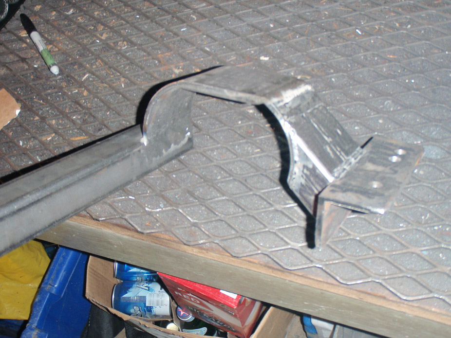
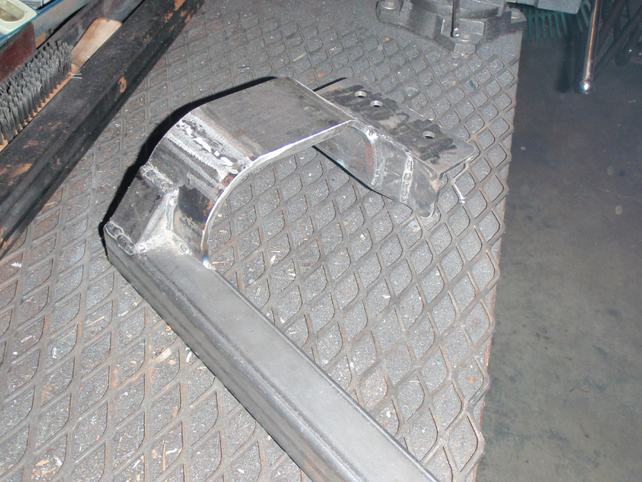
... like I said, a clearance mission...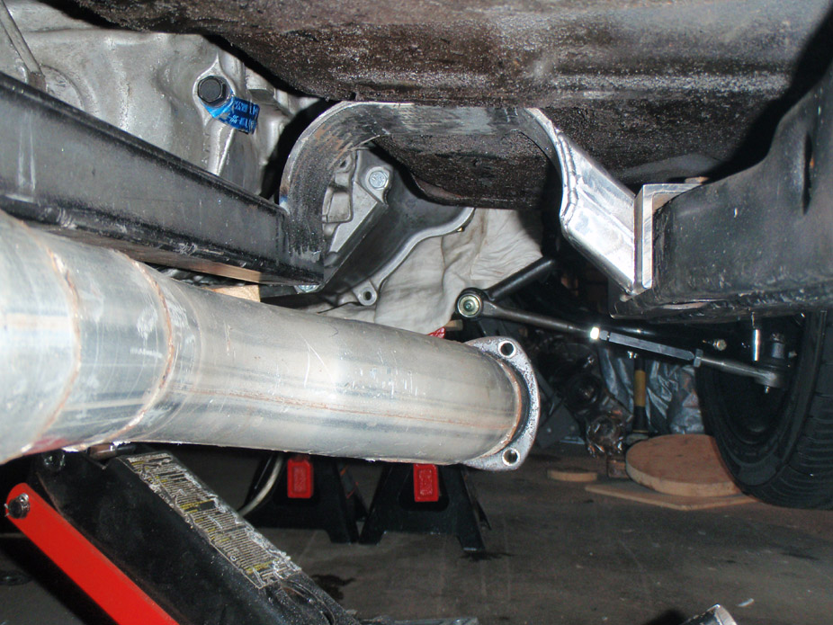
...shitloads of it (that's measured off of bottom of subframe)...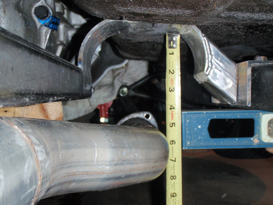
2-5-2010
X-member is FINALLY done!! I'm somewhat of a perfectionist but I finally had to call it and finish 'er up, not prefect but gets it done. Correction, I think I might want to lap-weld on a 3/16" piece of flatstock to reinforce the weld connecting the bottom flatstock to the left side...
Special thanks to Marktainium for confirming what I suspected but did not want to admit... making it a two-piece design...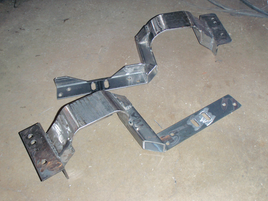
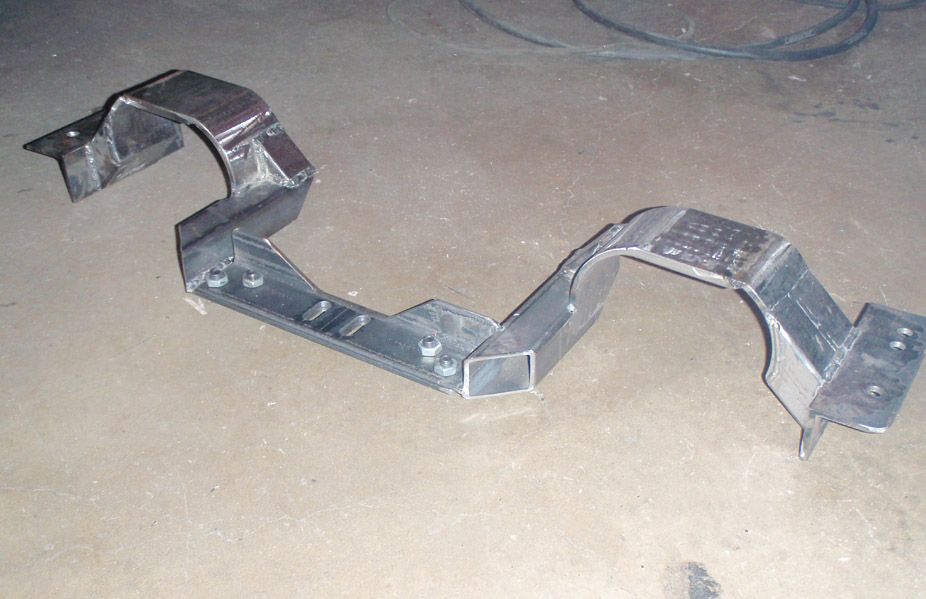
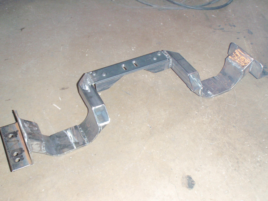
...and how does it fit? Excellently Still have to make multiple adjustment spacers to slip under the trans mount...
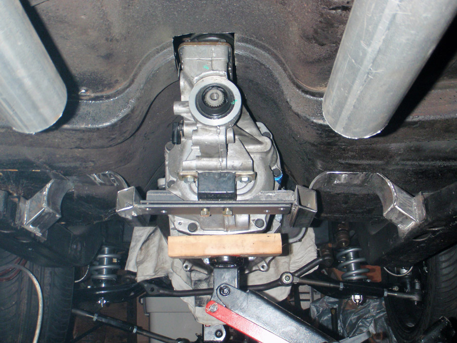
2-7-2010
Hmm what year is your truck motor? Some came with the FPR on the rail with a return (like yours if your reply was describing your own intake) or a returnless system, like mine. I'm not sure what pressure the truck FPR is set too, presumably something similar to the Corvette one, but if you're planning on boosting, I would HIGHLYsuggest ditching the truck FPR for something that can flow higher and/or have some adjustability. Depending on your planned power, the Corvette FPR might even be a bit restrictive with 3/8" in/out and a 5/16" return. If you decided to not use the on-the-rail truck FPR, I'd suggest locating a newer truck cross-over tube so you can safely just feed it one pressure line, as opposed to modifying/plugging the one you have.
How high are you planning on boosting? I'm not positive on this, but I think 3bar is aftermarket territory, and the Cobalt SS one is 2-bar... that's what I plan on doing.
Also, it's nice to have an adjustable one so you can nail the pressure you desire, or even have the pressure ramp up with boost... Some people like to get big injectors with no change in fuel pressure and just have all the fuel tables modified on the PCM for the boosted setup, but if you have large enough injectors to satisfy high rpm/boost, the injectors will have a (slightly) harder time at lower rpm & idlebecause of their decreased spray times (injector resolution). Lots of people swear that 60+lb/hr injectors can be tuned to have really good idle characteristics, but to me this seems like creating more work than necessary.
I'm planning to use an LS2 tune along with the LS2 42lb/hr injectors (got mine from an LS7) and a ramping adjustable FPR that increases fuel pressure 1:1 with the increase in boost. I'm planning a MAX of 12psi for now (hopefully I don't get greedy/need to crank it for a while ), and so from idle -> full boost the fuel pressure will ramp 58psi -> 70psi... This was pretty well confirmed by multiple common fuel/boost formulae as well as (too much) time searching Google.
This seems like the easier way to me, starting with a stock(ish) setup and turning up the wick to pump out more HP, as opposed to just tuning larger injectors and having to start from scratch. This will be a good baseline to start driving the car a bit, but of course to squeeze more power out and make it most efficient, a unique tune on the dyno will be required pretty soon after.
Also, not sure what is going to go on with the MAF, think I'll keep it on there since I'm not planning on doing a speed-density tune yet, leave that for when the I want to squeeze more power out of the car. Hopefully the MAF doesn't get pegged with the 7-8psi I plan on starting out with.
OK, it's Saturday night, I need to go drinking... cheers!
2-8-2010
Hmm... I believe that the LQ4 only started being used in teh Express van in 2003... 2002 would have had the 5.7L smallblock, is there any way you can confirm where it came from?
Regardless, I think LQ4's come stock with 28 or 30 lb/hr injectors... but not positive on that. Even if you ramp the hell out of the fuel pressure, I'm pretty sure you won't get near enough fuel to supply 15psi. 15psi would be 3bar territory I'm pretty sure, plus that would give you room to grow boost-wise ( !!). Siunce you plan on doing alchohol injection then, that'll help, but I would still recommend a larger injector.
When you get larger injectors, if you were to keep stock settings, you'd have to decrease the injector spray time to let less volume, but since you are now boosting and need more fuel anyways, the only way you can program the fuel tables to spray the proper amount is by tuning/dyno time.
The truck intake is so tall that most other injectors are short enough (in comparison to stock truck injectors) to need a spacer in order to mate with the stock fuel rails/crossover tube on a stock truck intake.
However, I'm really no expert on this so it's best to venture over to the Forced Induction or Fueling Injection sub-forums...
2-21-2010
I haven't been working on the car too much recently, been out enjoying the whole Olympics atmosphere, I gotta say I'm really proud of our city, and the weather has been absolutely phenomenal; going downtown to see the different venues is such a trip, there are SO many people around it's unreal... good times!!!
Gotta love "progress"... car got chopped up even more :S
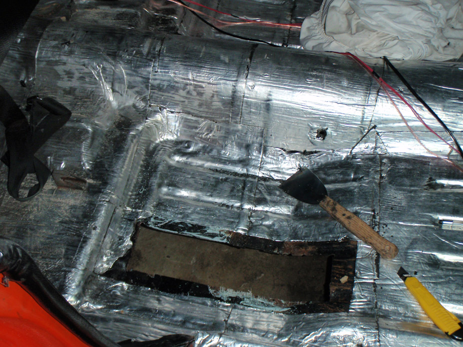
Some ignorant asswipe previous owner decided that instead of properly fixing some pinhole rust, they'd just slap on a bunch of fiberglass and call it a day. Sometimes the cure is worse than the problem, I'm glad I found this... look how thick it was laid on!!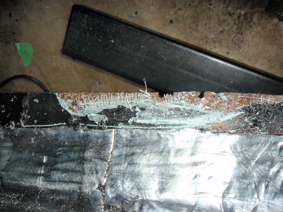
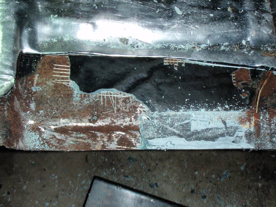
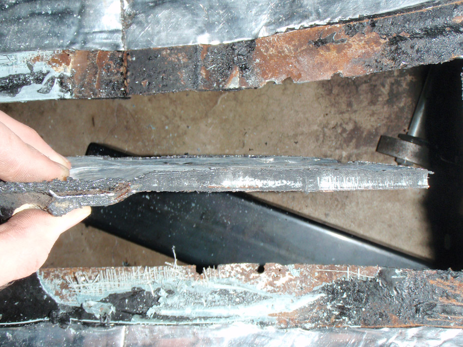
Luckily it seems like most of the cancer was actually in the hunk of floor I chopped out, talk about getting lucky/killing two birds with one stone!!
...and this is what's going inside that hole...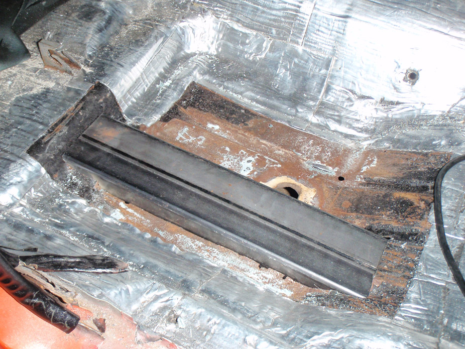
The top half of the subframe connector will butt against this ridge in the floorpan. The rear framerails have formed endpieces that connect to this ridge..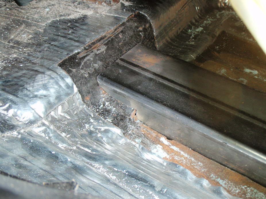
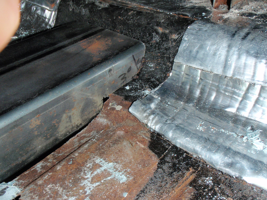
The bottom half of the SFC will poke below the floor and end up having plate connecting it to the actual framerail...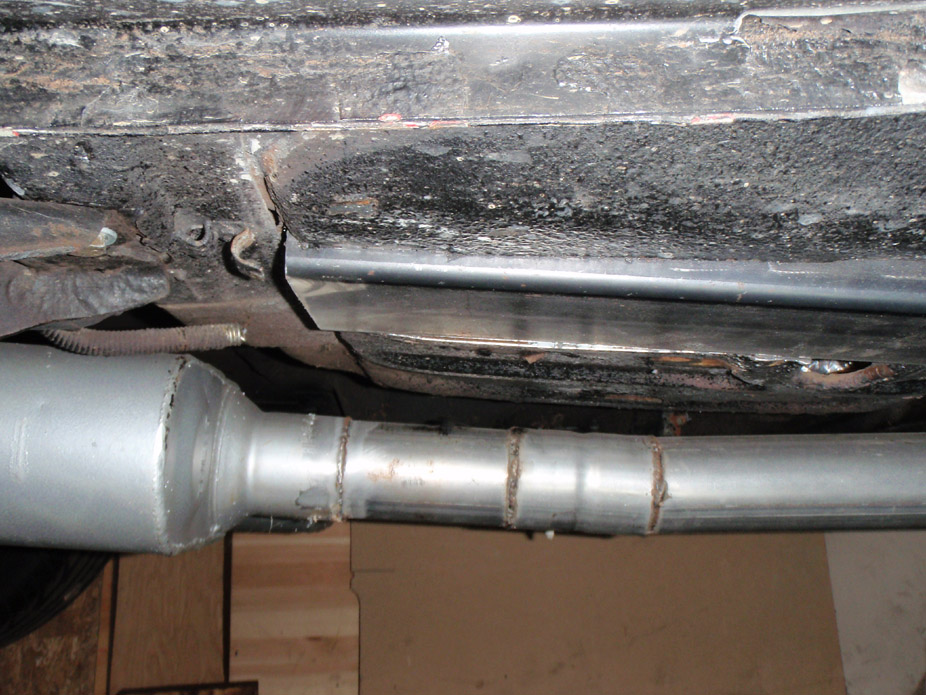
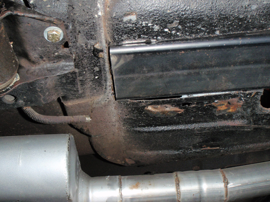
I'm thinking I'll probably add an extra plate connector piece to reinforce the front end welded connection to the subframe.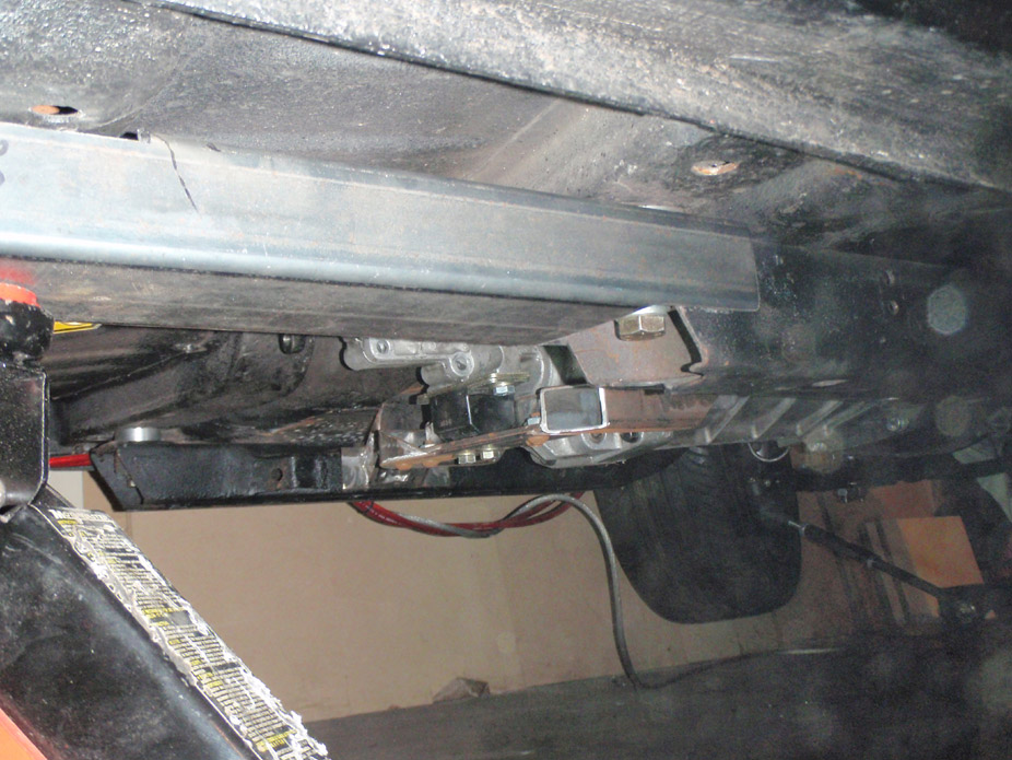
They're 2 pieces mitered at a slight angle. There's a notch right around the joint so the front piece can be welded around the under-seat-floorpan-cross-brace-thingy...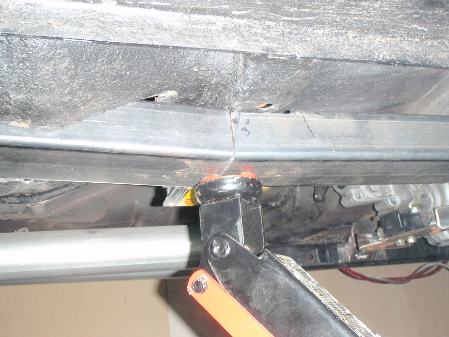
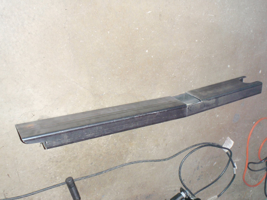
And they'll end up being pretty stealth...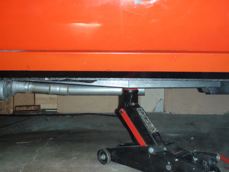
2-28-2010
Took this pic today and thought it looked kinda menacing... for some reason this view just got me really stoked again to work my *** off on this car!!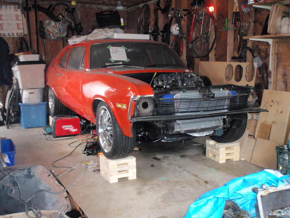
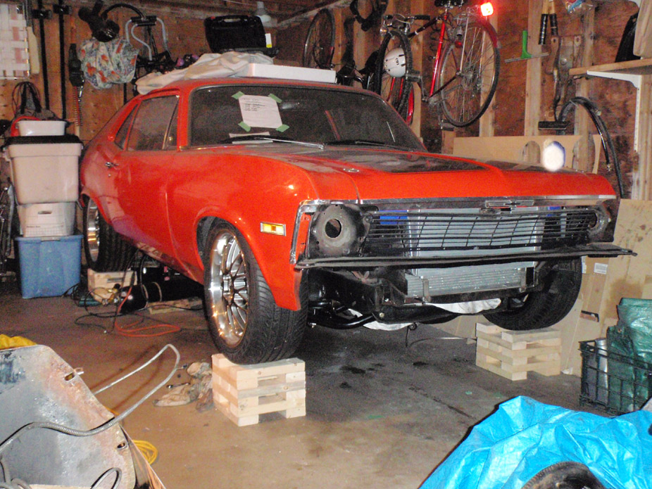
4-11-2010
**** I know I've totally been neglecting the Nova and I feel terrible about it, but this has been distracting me...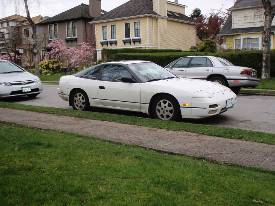
and so has this....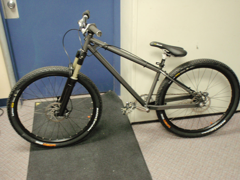
which i do this with...
Consider that my update!!! haha
7-12-2010
Ok here is a long-overdue mini update. I'm currently not in the same city as my car until August, but I returned this weekend to do a bit of work.
I had left the subframe connectors half-finished before I moved away a couple months ago, and I had tied the 2"x4" into the floorpan above the rear framerails on the inside of the car, but still had to tie the bottom bit of 2x4 end to the framerails...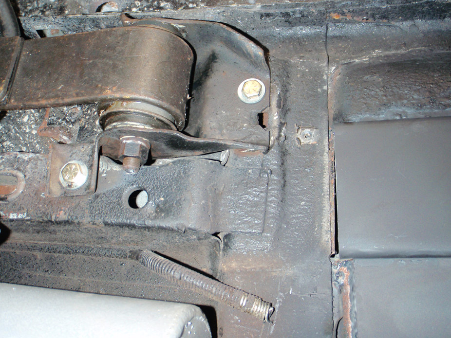
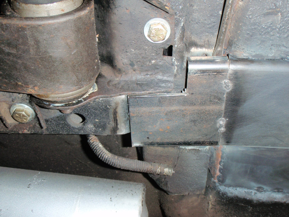
This FINALLY wrapped up my subframe connector fab work which had a 3-month long intermission...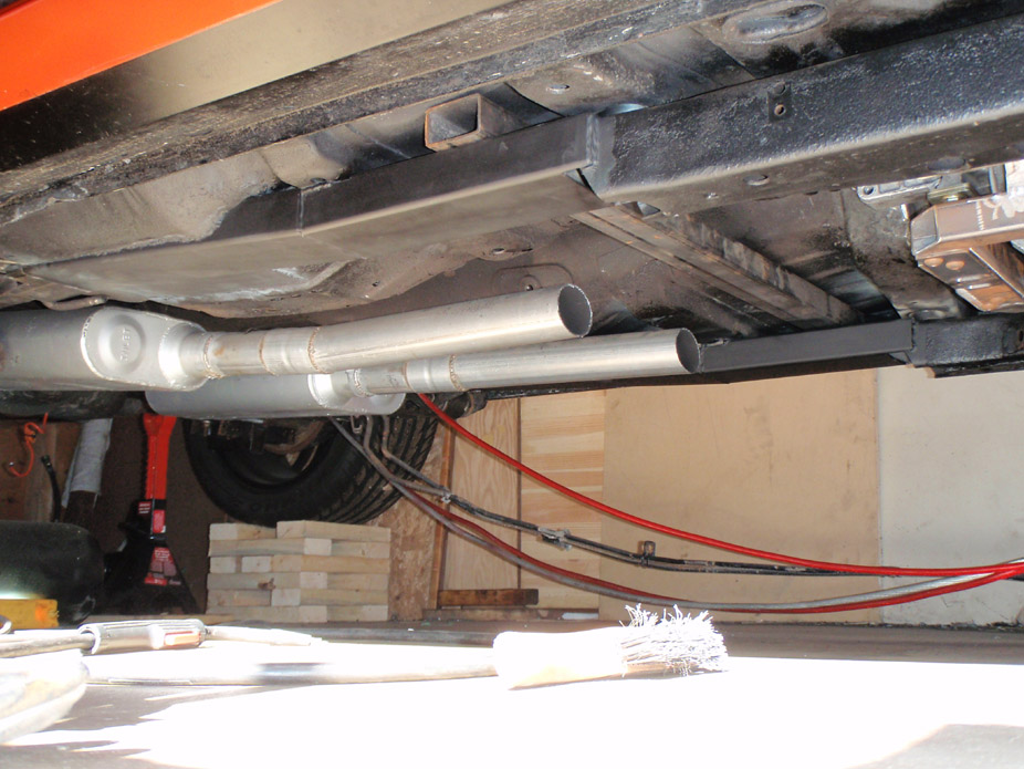
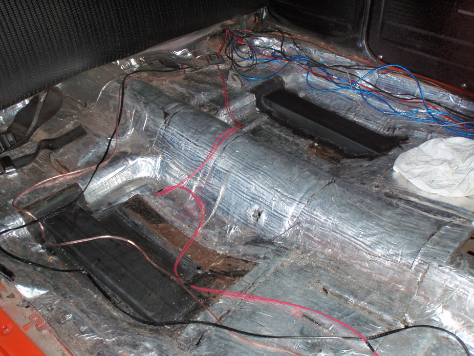
With the subframe connectors out of the way I of course had to create another problem to fix and cut a big hole...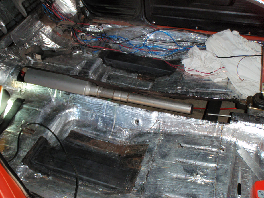
Reason is due to tranny/driveshaft tunnel clearance, or lack thereof. For mockup I used a length of 2.5" pipe with a wood 2x4 to simulate clearance, and the trans spacered up to the max height I'd want it adjustable to...
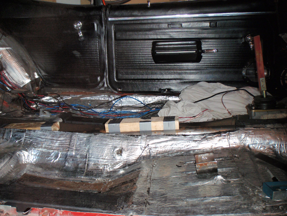
Then also thought it'd be a good idea to throw in a driveshaft loop for safety, since I have the metal already anyways...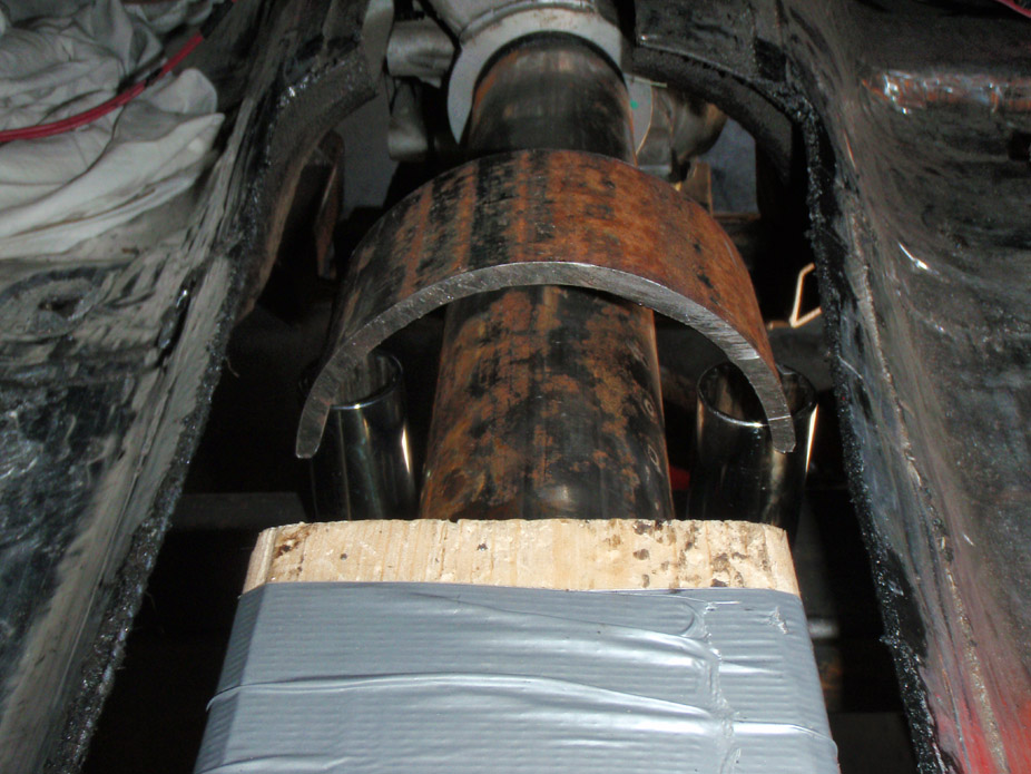
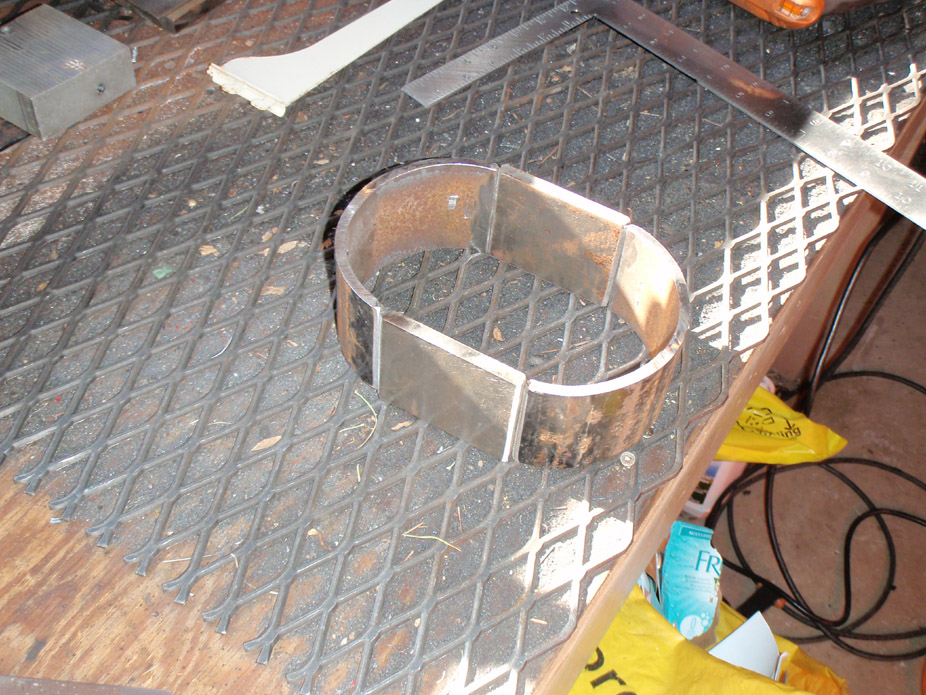
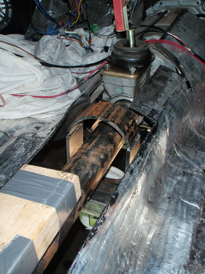
I got as far as mocking up the loop, but I'm optimistic about the end of all this under car metal fab, just need to weld the loop in and bend some new trans tunnel sheetmetal, and then I can foget about all that crap and start mocking up turbo hot side!!
Also, here's a teaser for what I've been working on when I'm not close to my car...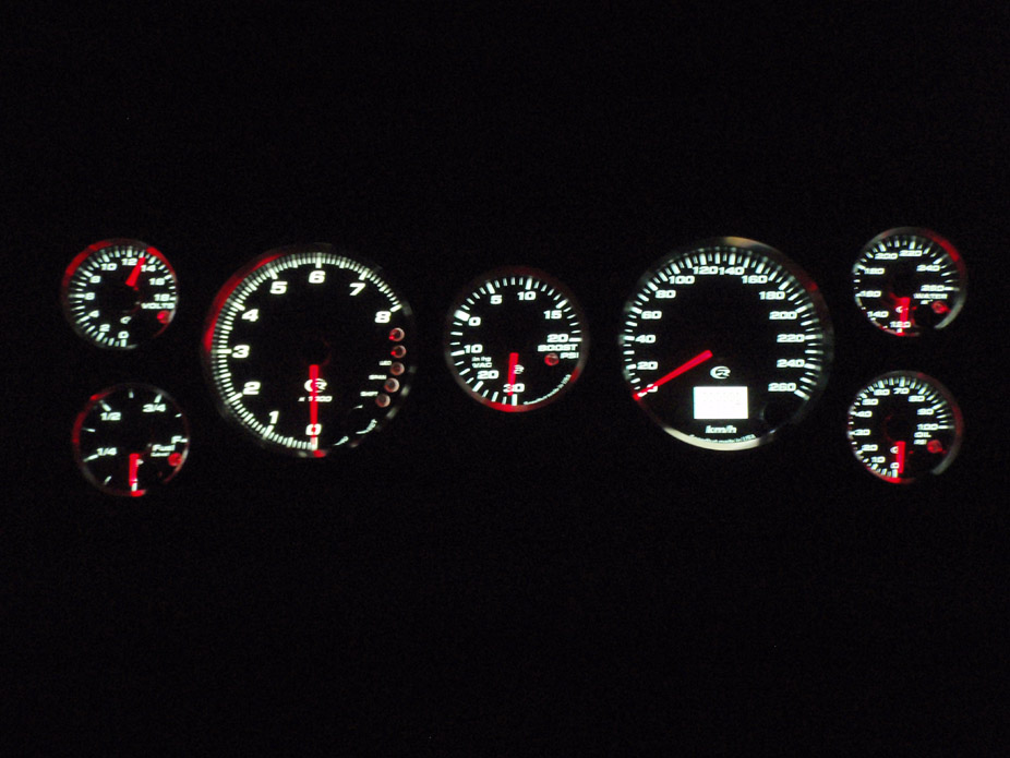
7-16-2010
Haha all I can say is I owe this recent re-interest in the Nova to a stupid driveway at my house... since I couldn't lower the 240sx anymore I decided to stop tinkering with it until it doesn't need to be a daily driver anymore...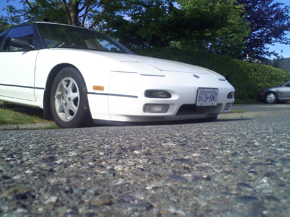
7-20-2010
Hmm I was considering buying one of those but thought that, much like an AFRgauge, if something goes horribly wrong it'd happen almost too quickly to tell. I'm almost thinking of away to have the engine cut out if the fuel pressure dips below a certain pressure.
Anyways, I was going to save all these pics for when I completed the gauge panel, but school has been consuming my time, so I guess I'll call this update "Gauges Part I"...
The SpeedHut Revolution Series gauges...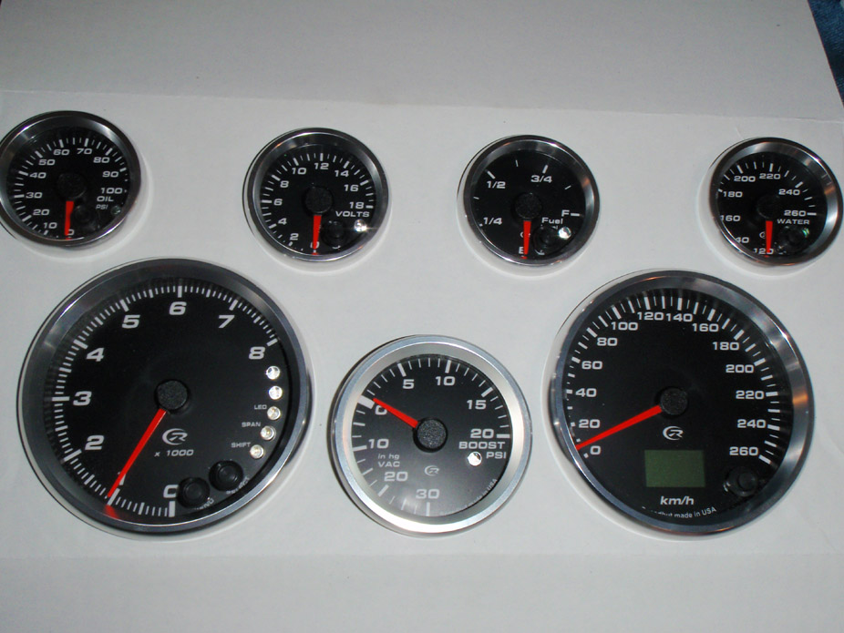
Neat wiring, each gauge with its own mini harness...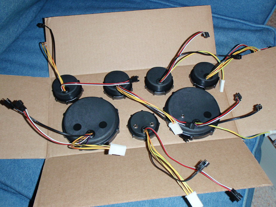
Each gauge is super easy to dismantle partially or fully, depending on how you want to custom mount it. Also, although it doesn't look like the typical cosmetic weave, the buckets are all carbon fiber...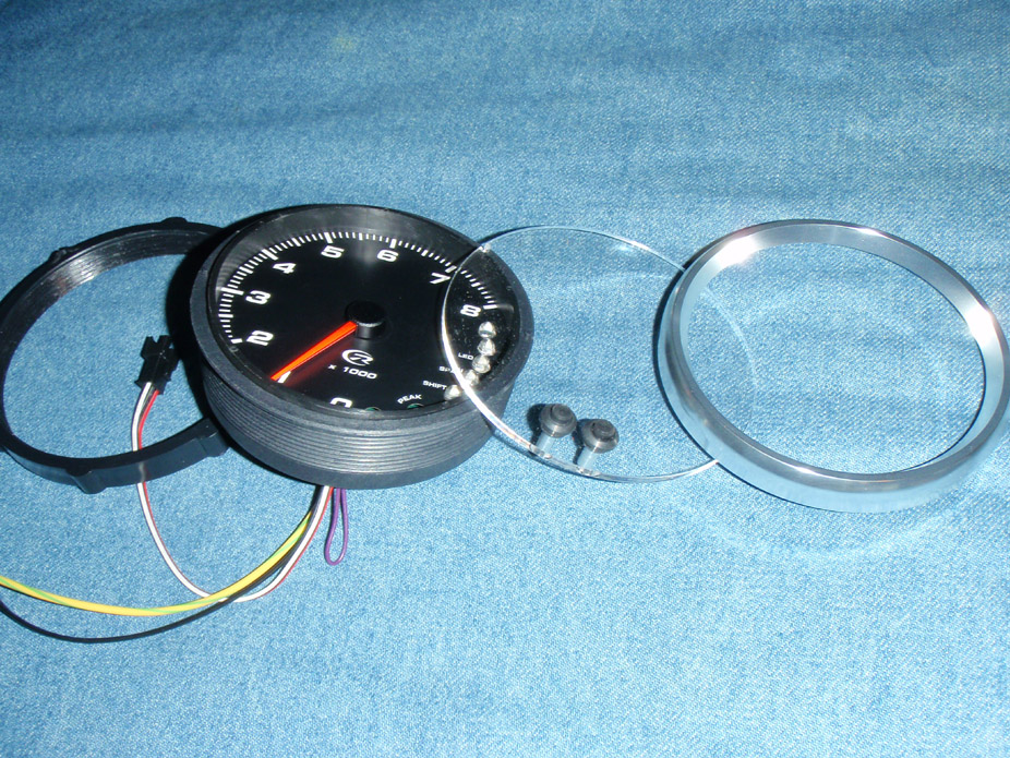
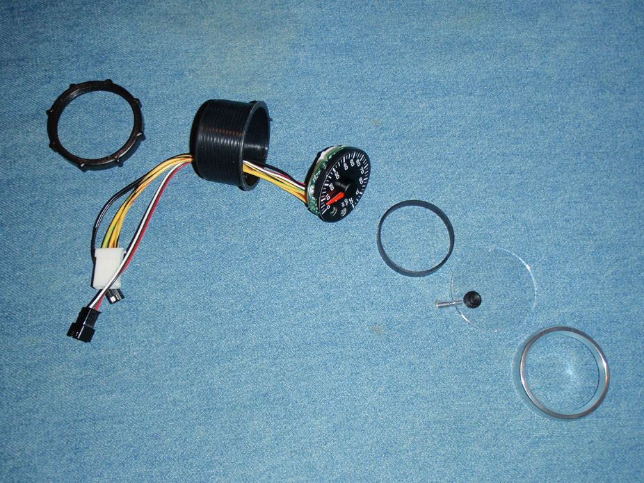
I love how each gauge has an awesome package of neat, simple wiring...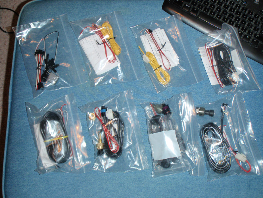
Pretty sweet OEM-style wiring/connector and OEM temperature sensor, at least I'm pretty sure it's the exact same as the LS temp sensor...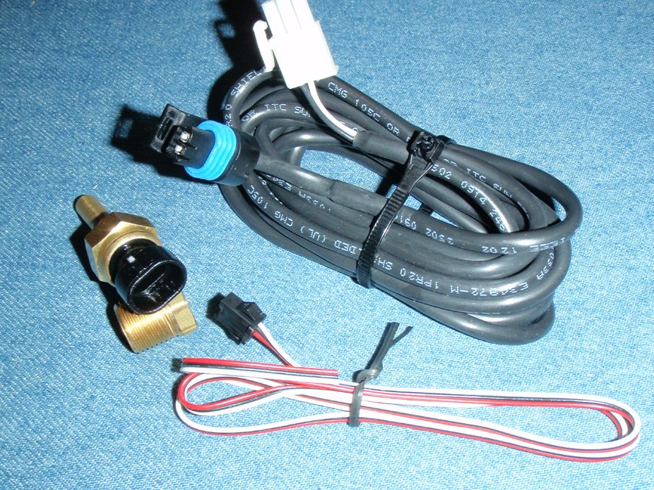
Pretty professional looking oil sensor too...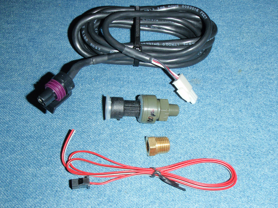
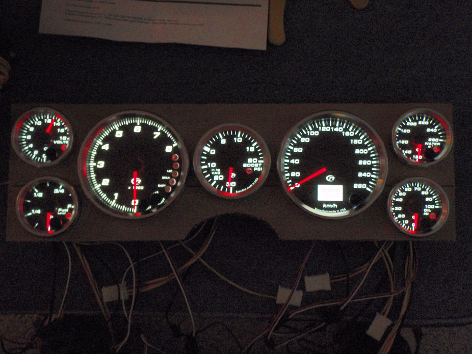
I love how these gauges look, they're modern & performance styling without being super ricey or euro, or Autometers haha.
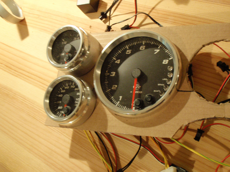
I'm not a huge fan of the typical Covan's replacement panel and generic Autometer 3 3/8" gauges mounted flat, so just to be a bit different I'm reusing the stock panel but chopping it up a bit and plan on making an insert with a 3D staggered-effect setup for these gauges using tubes. To start, here is a basic 2D layout of the insert panel...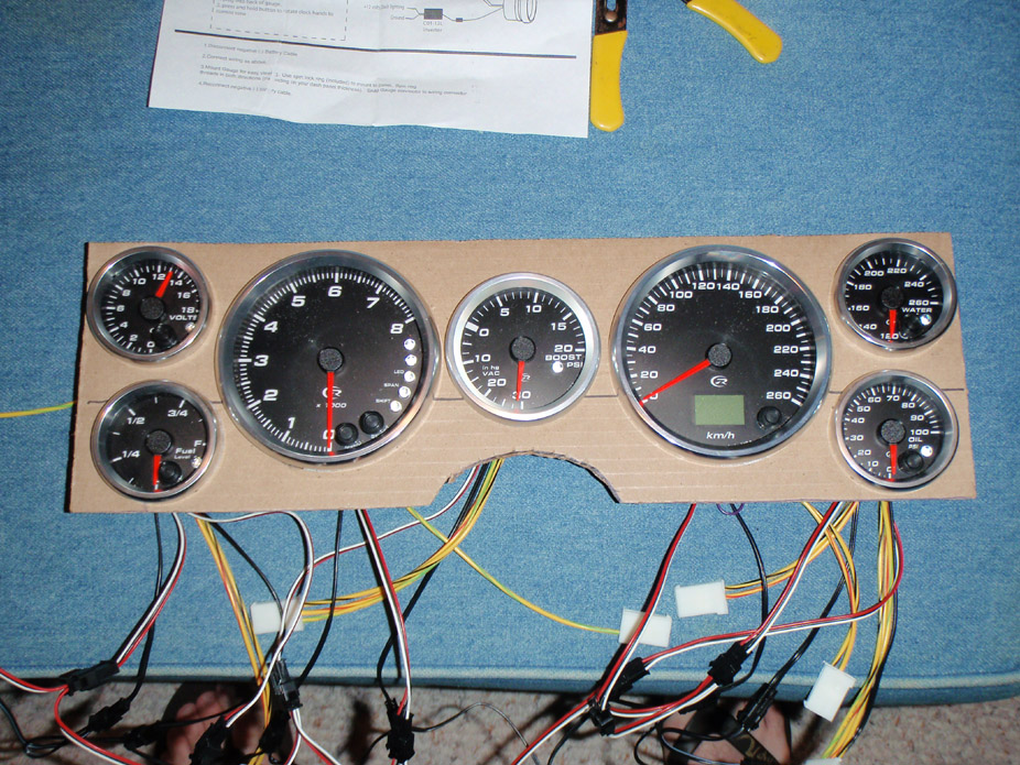
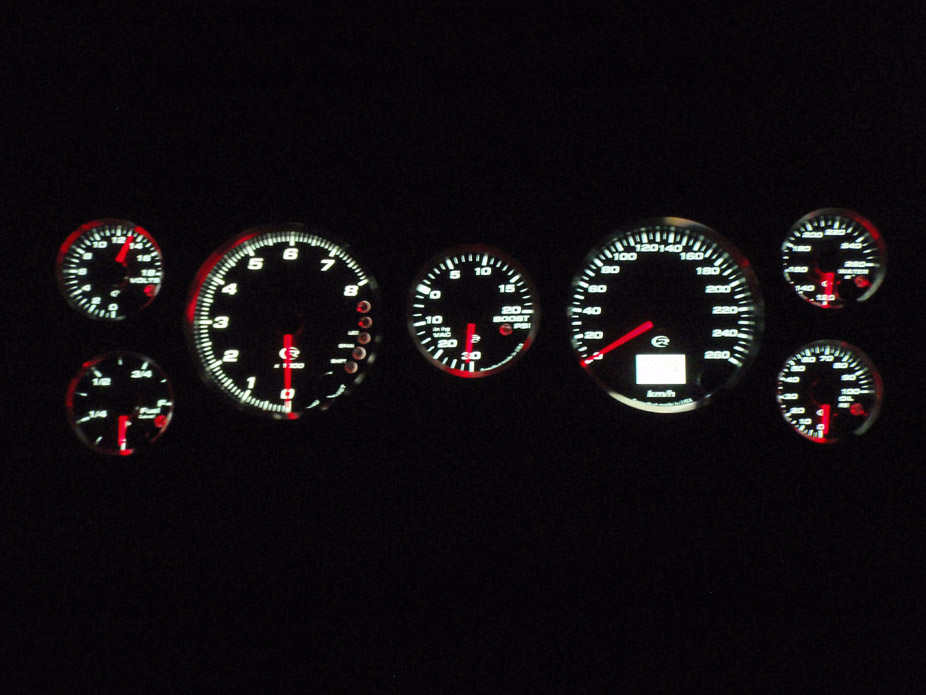
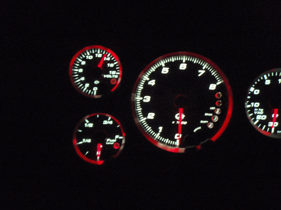
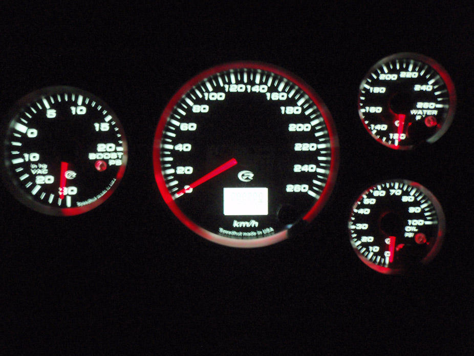
7-21-2010
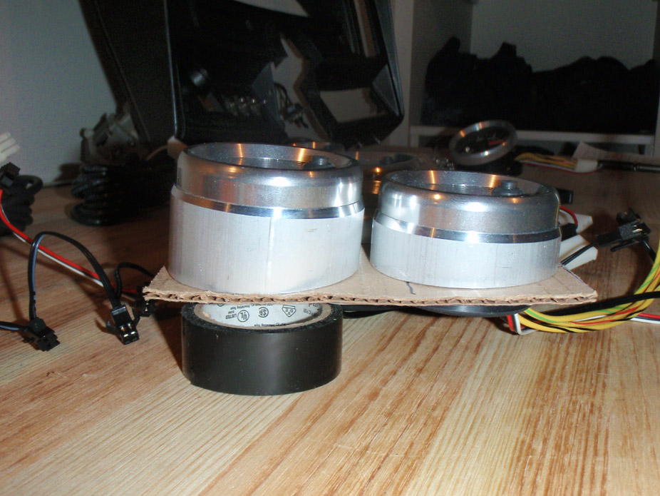
A little update, made some test gauge "pods" to see if the angle/stagger gave the 3D effect I was looking for, I think I'll go through with it for all the rest, I want the tach/speedo to stick out more than the rest...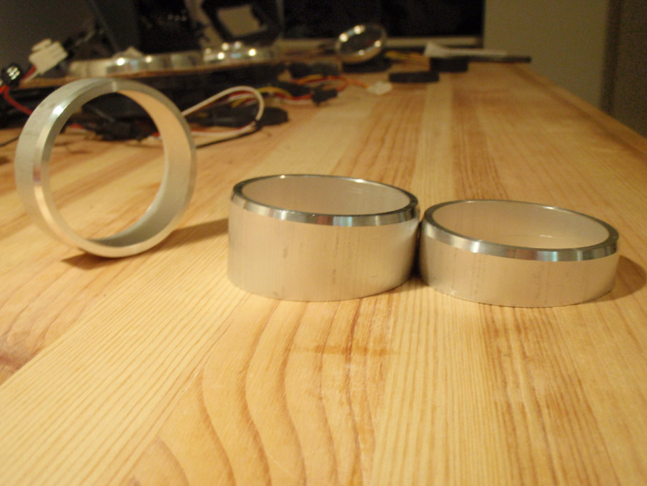
Started gutting the dash panel to make room for the instrument cluster...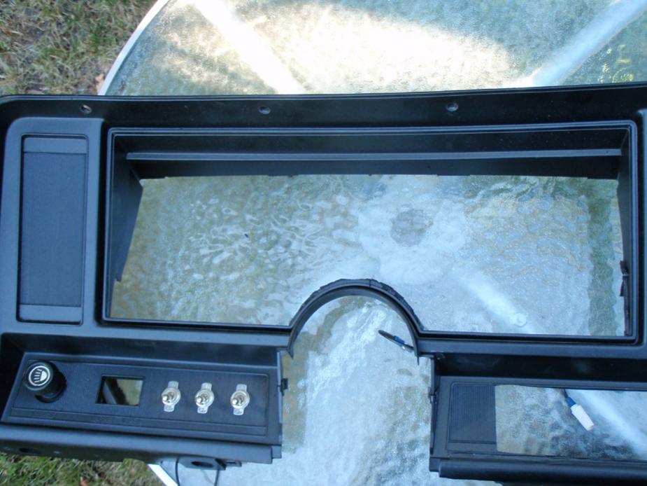
7-23-2010
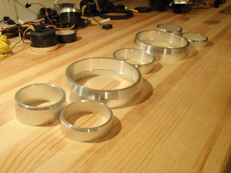
Imagine that they mate to flat plate right above where the round black pieces are sandwiched in there...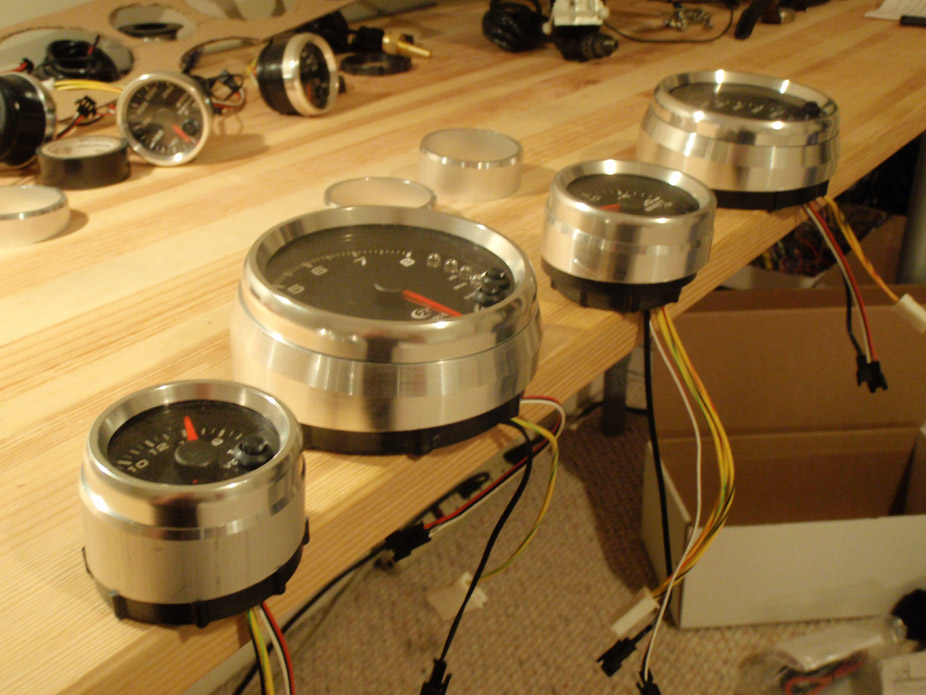
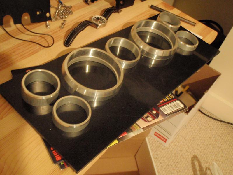
10-23-2010
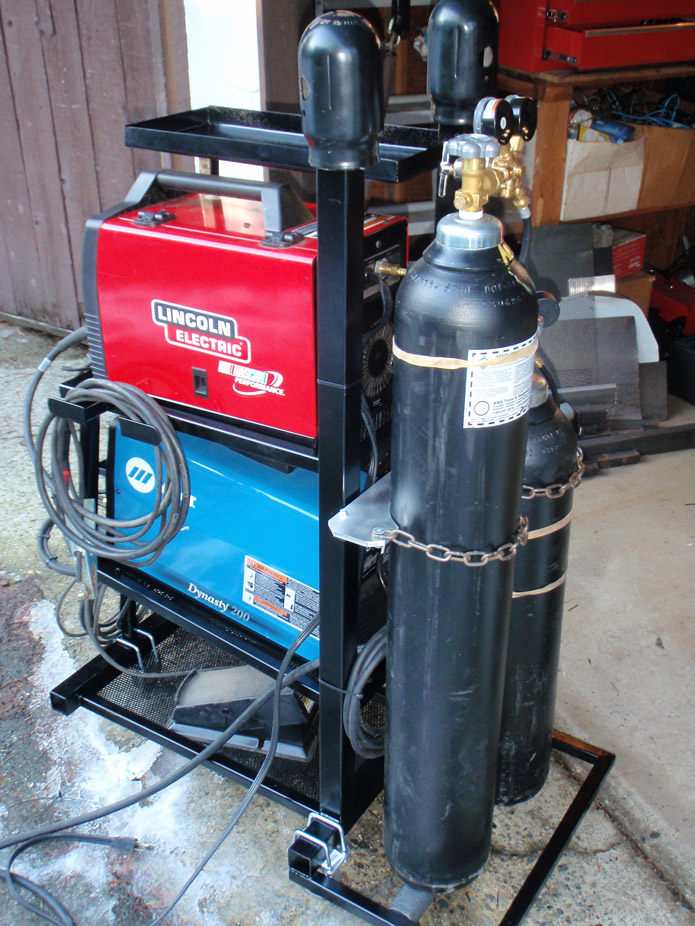
MINI update: for the last month and a bit I've been working on a couple little things, but mainly making a stupid welding cart which is taking forever with all the miters and stuff. I did make a tiny bit of progress elsewhere on the build, shown below. Full-fledged fabrication and REAL progress should resume within the next week or two...
Made this back in the summer, pretty hard when you only have a bench vice, some 4" tubing, and a big mallet...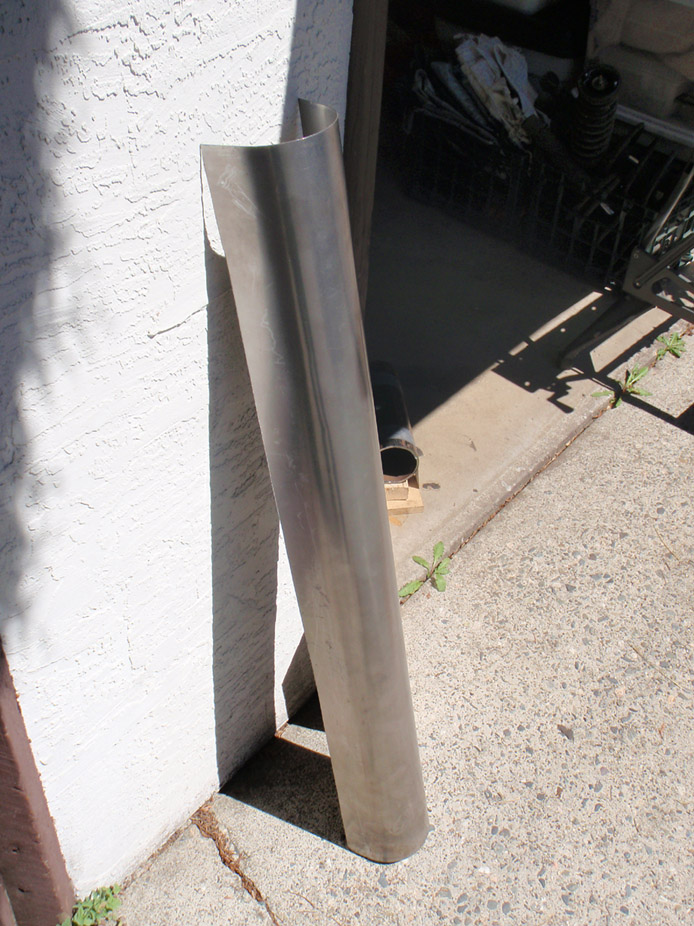
Of course it fits perfectly...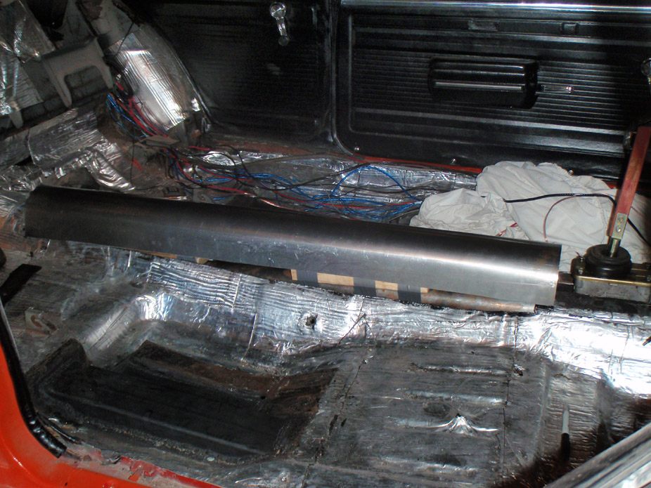
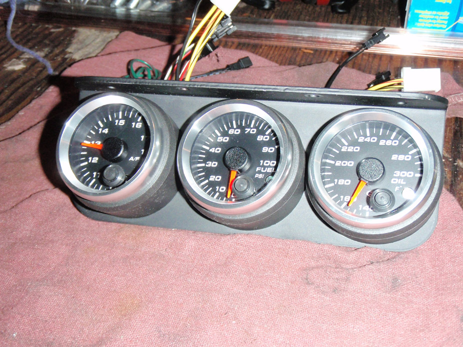
Got a couple more gauges that will go in the way-less-custom hanging 3pack panel. The sure do look cool (IMO)...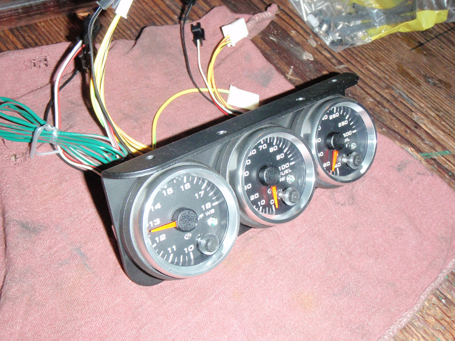
Just for ***** I made a couple toggle switch separator do-hickies, they took a lot longer to machine than they'd look, but I think they add a tiny bit of modern class that'll go with the modern gauges & machined aluminum bezels...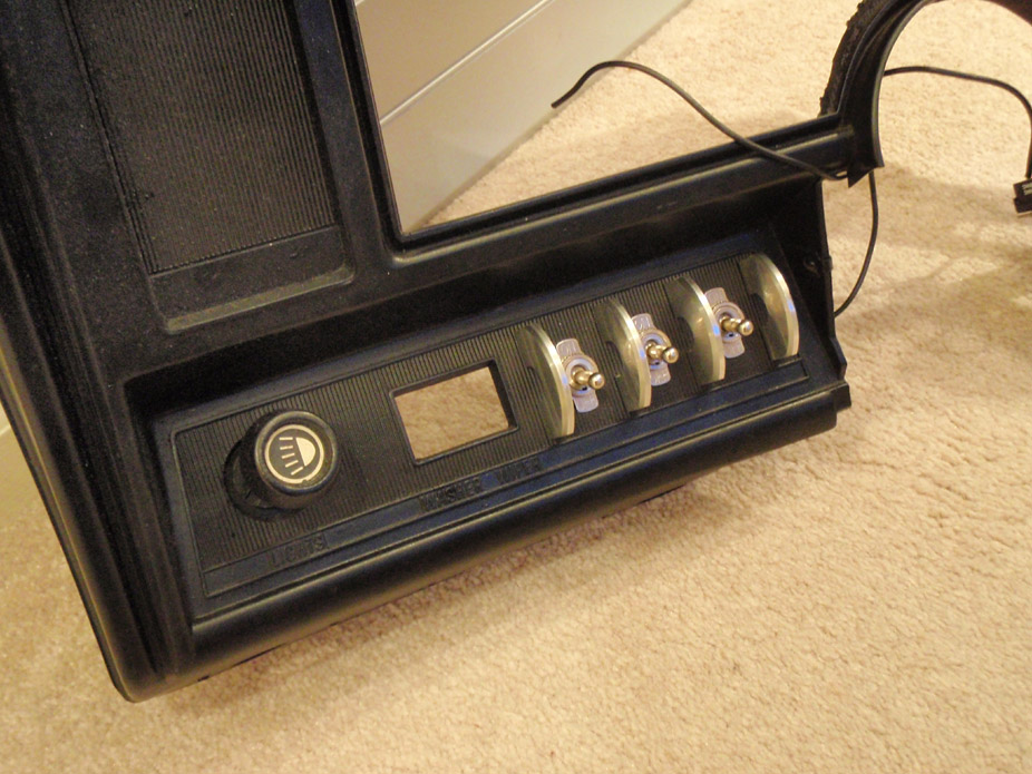
11-21-2010
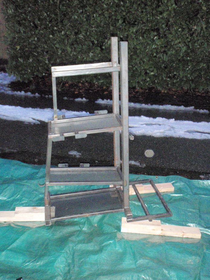
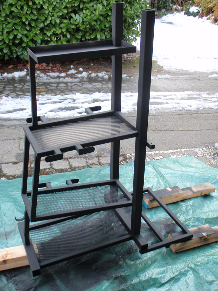
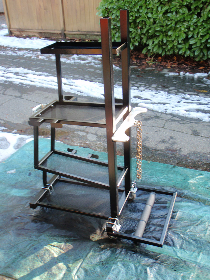
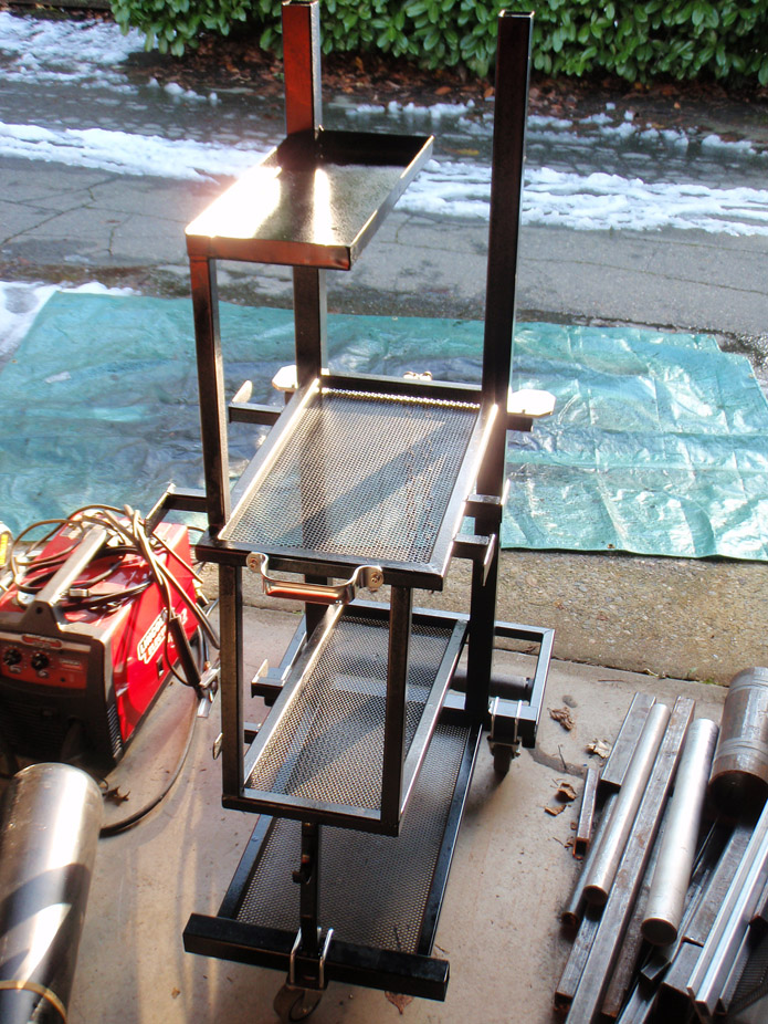
Alright so I have a very mini update, this workterm has been crazy busy so when I do get a chance to go out to the garage, it's been working on this , which has taken far too long, but now it's done so I can start on the car again!! Unfortunately I lost just about all of the weld pics...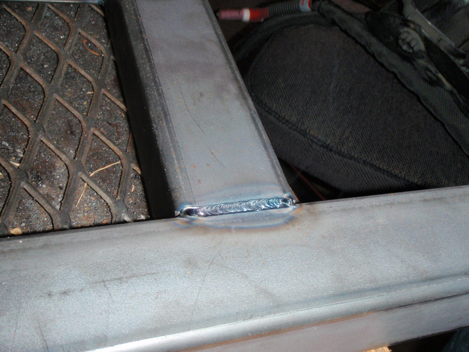
11-30-2010
So work on the car resumes for a bit here.
Ordered a bunch of 2.5" x 0.063" mild steel tubing and bends, with some brand new 2010 LS3 manifolds as well as an LS3 water pump, to give me a bit more room to work with up front for the cold side.
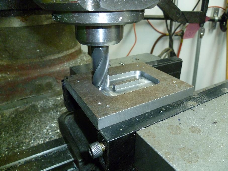
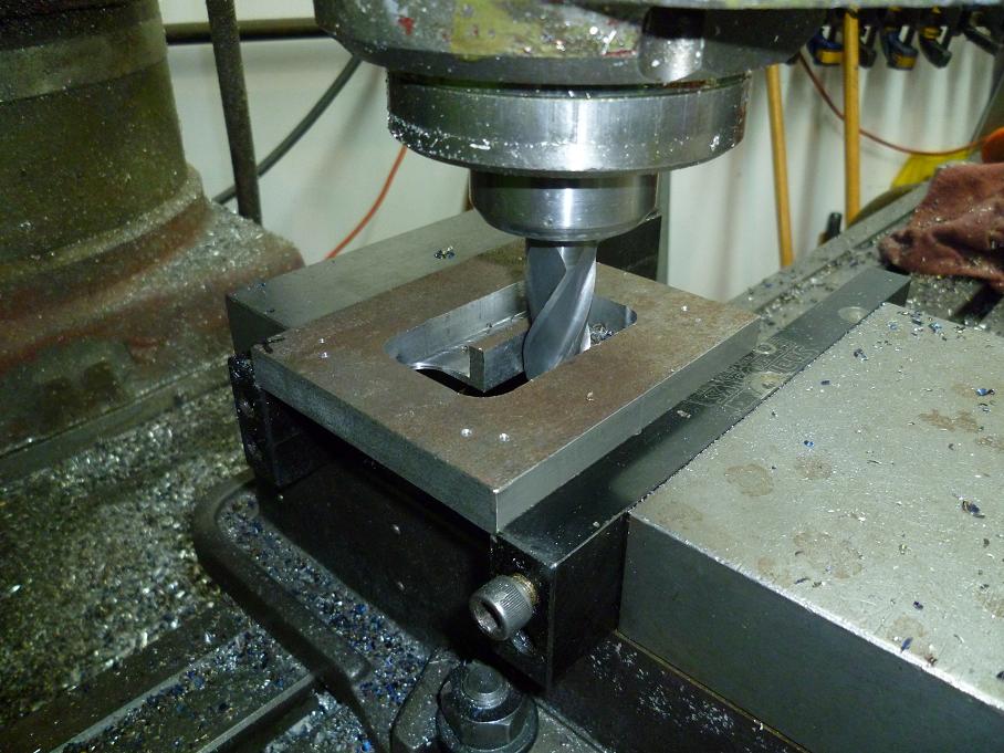
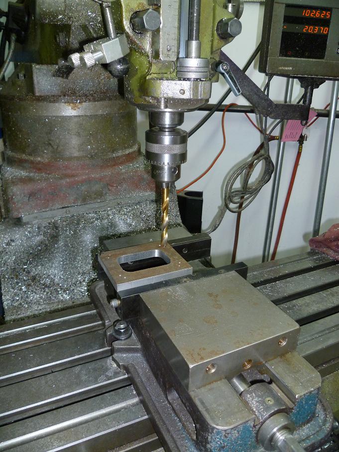
I milled a turbo flange. I'm still on the fence about this diesel HE351VGT Holset turbo, but since I have it and it was free, might as well give it a shot. Also doesn't hurt that its turbine inlet is so damn close to a T4, so I just made a T4 flange will a dual bolt pattern, so upgrading to a bigger T4 later would be easy(ish).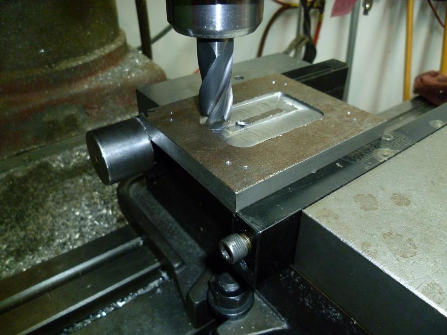
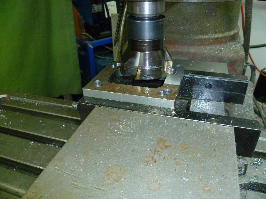
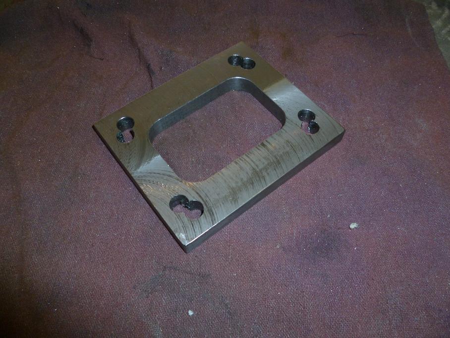
12-4-2010
Getting real close to finishing the gauge panel, liking what I see so far. Just need to make a bit of a plate "border" around the sides and bottom edges, and steeringcolumn arch, to give it a bit of a sunken look...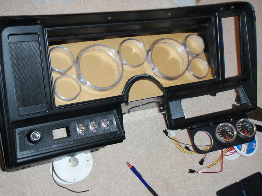
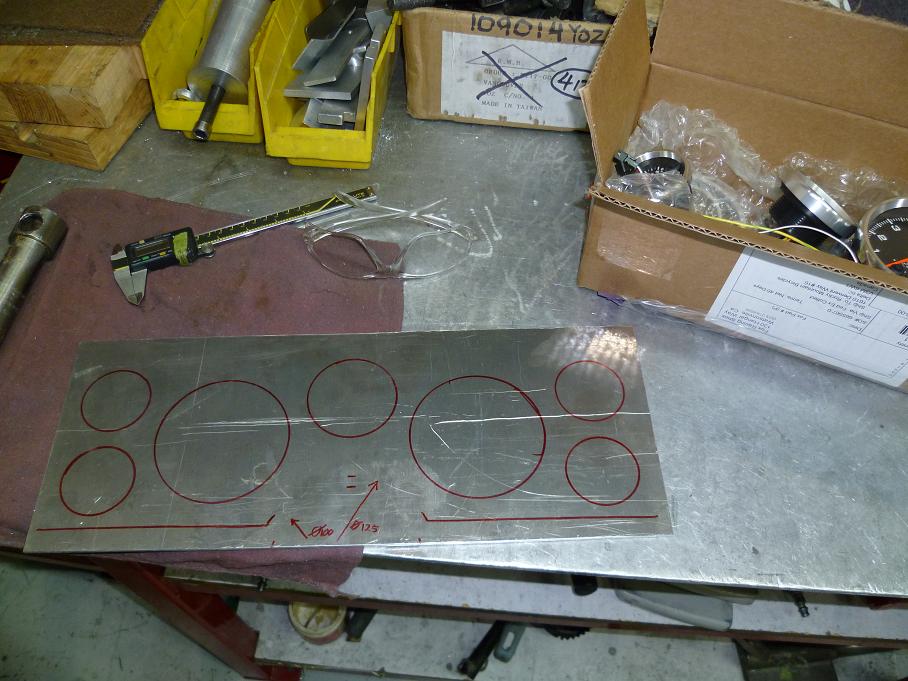
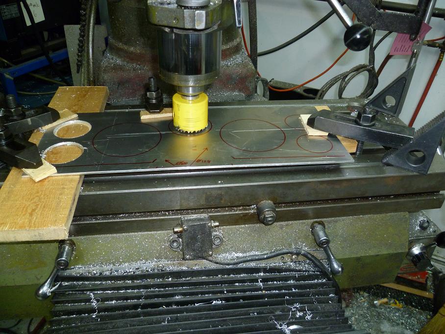
This was fun, felt like a big industrial etch & sketch...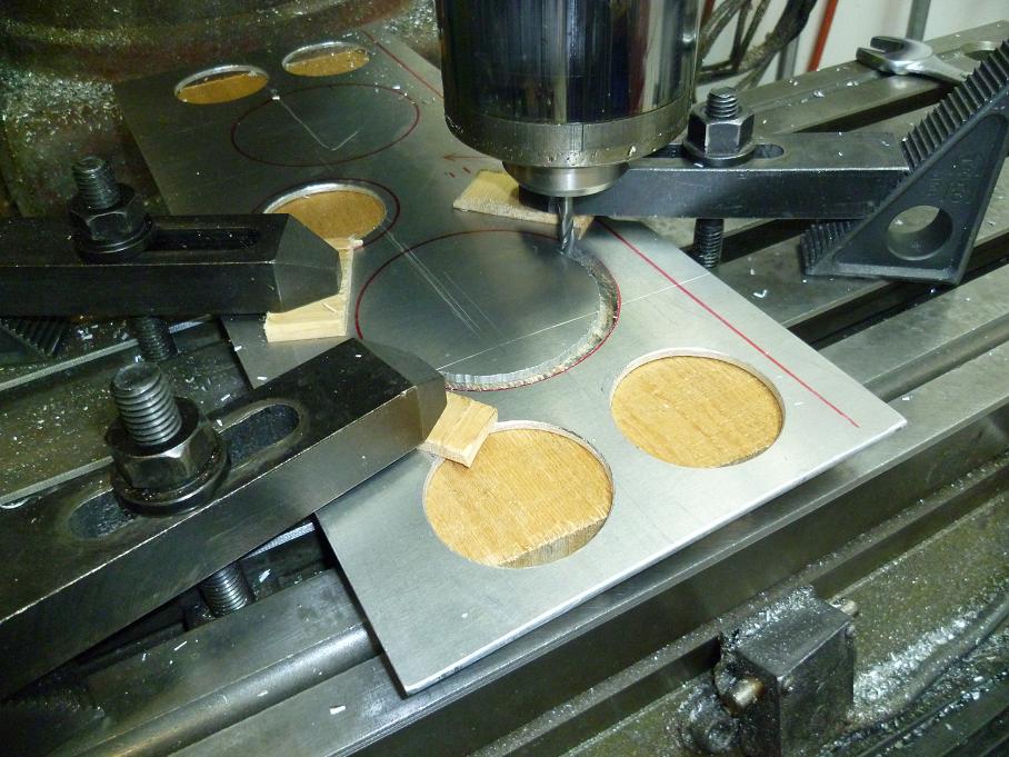
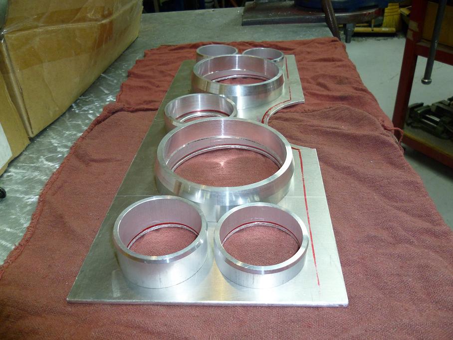
Clearance notches to tack the bezel rings in from behind to hide them...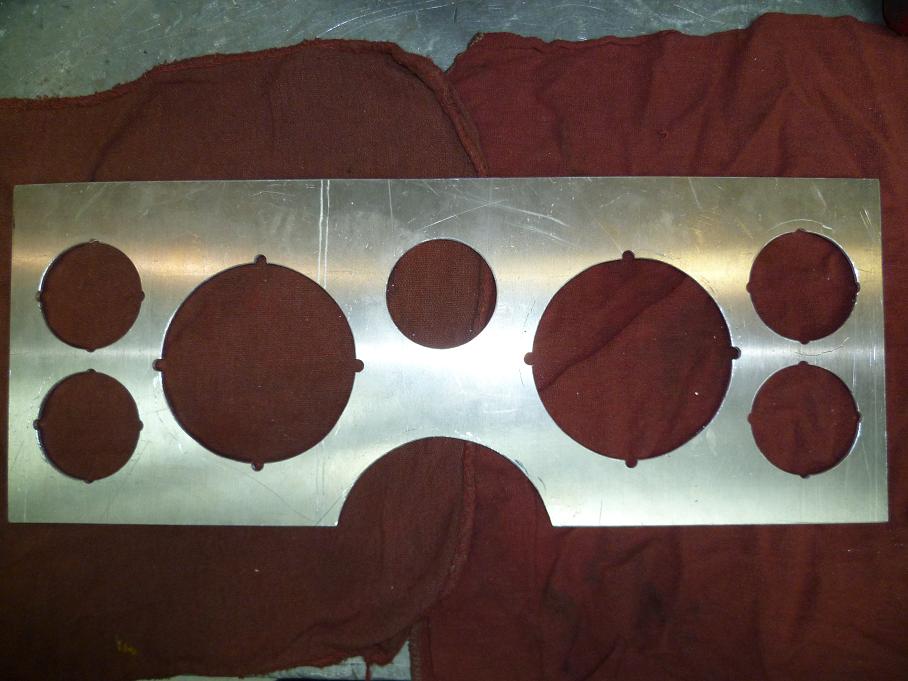
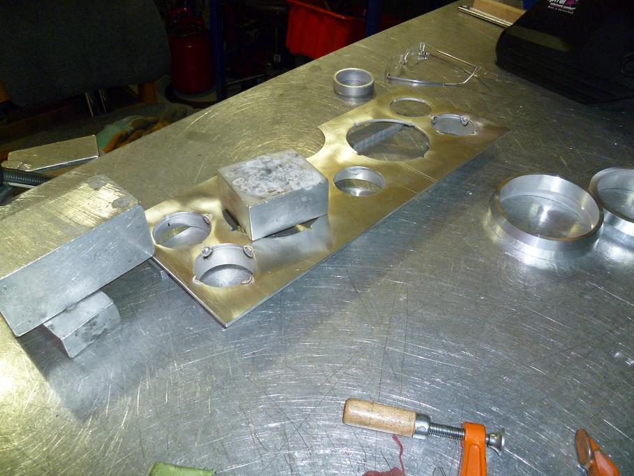
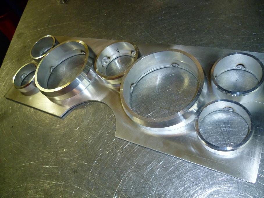
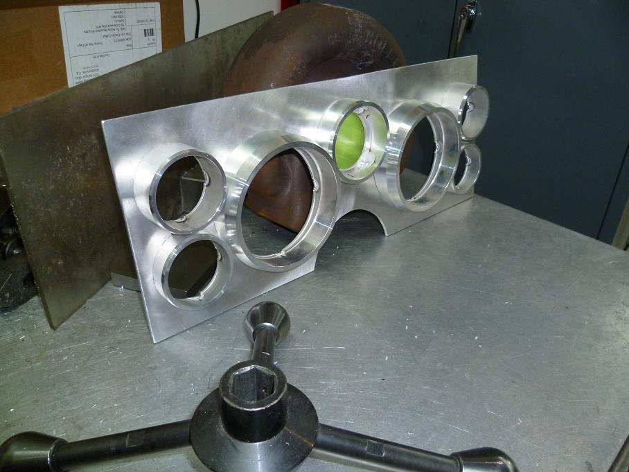
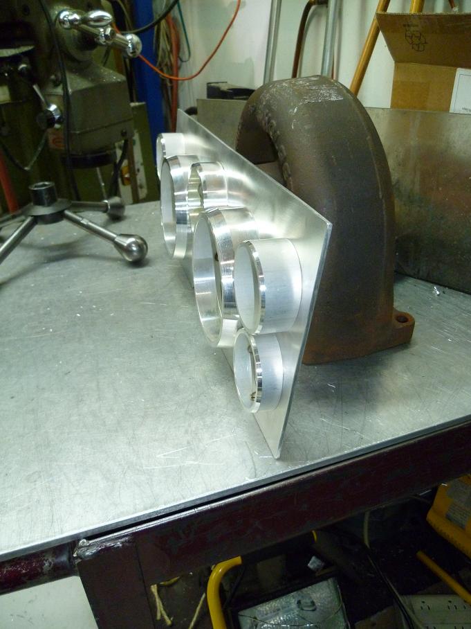
Mocked the gauges in for test fit and couldn't be happier.
Now to decide how to finish it, I want a rough matte black finish, thinking either:
1) bead blast and paint a semi-gloss black
or
2) anodize matte black and hope for a bit of a rough finish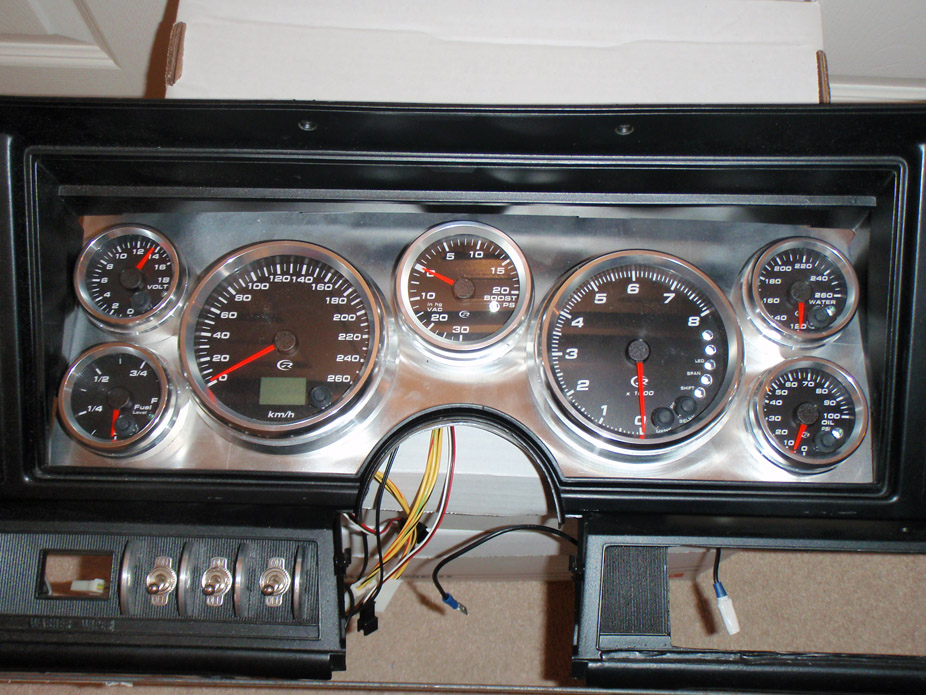
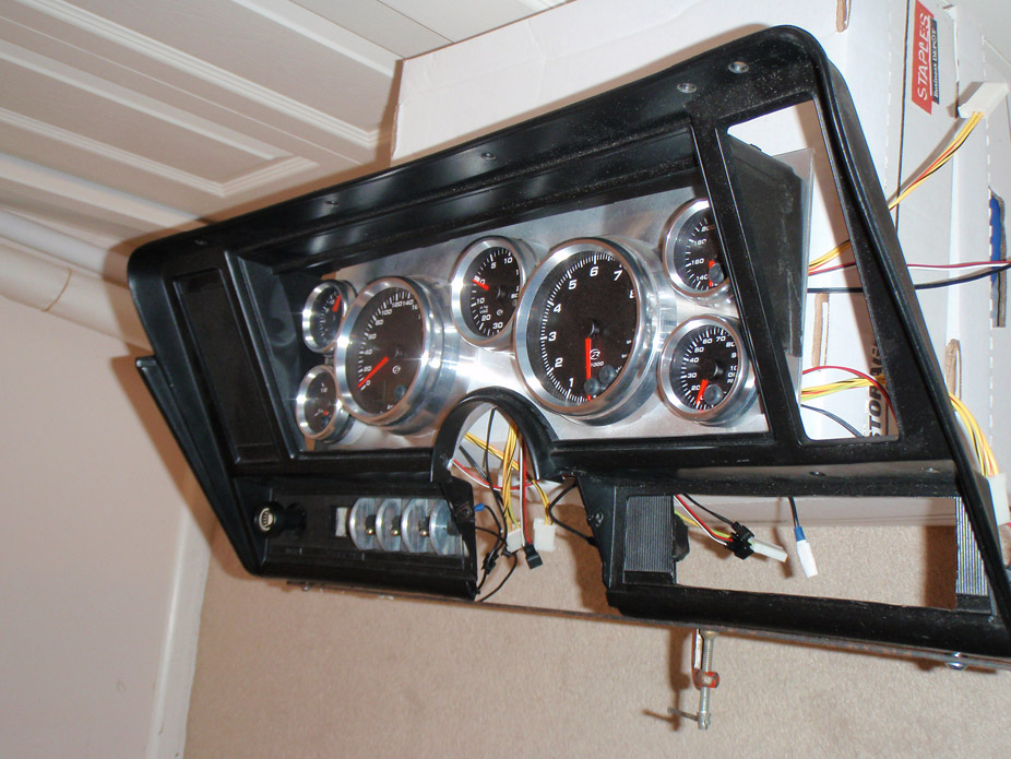
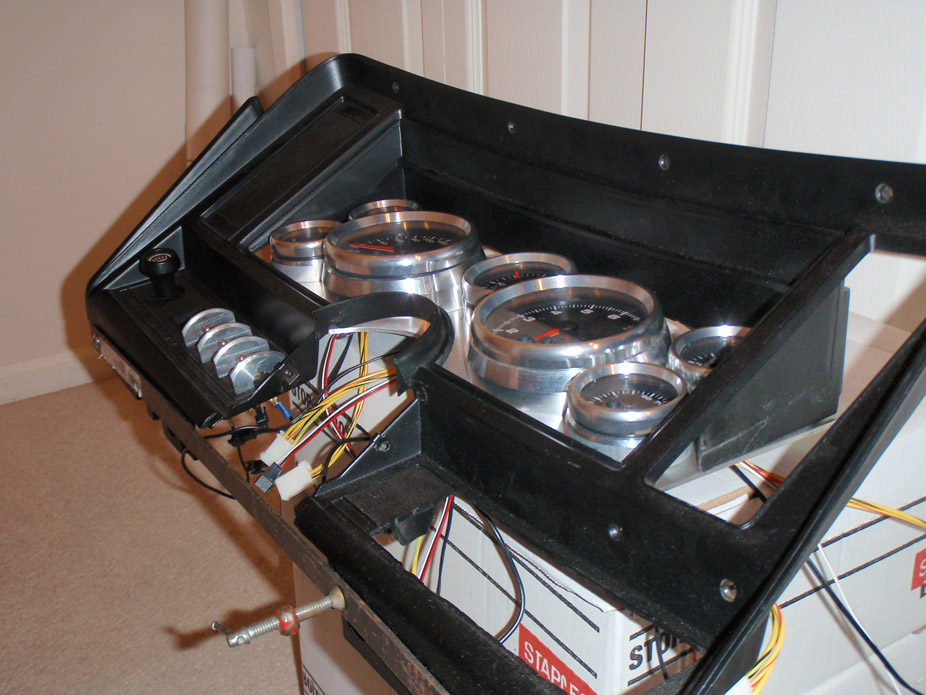
I think I am going to go black ano... I was quoted $60 for just the dash and only a couple bucks more if I add more pieces, so I'll have to see if there's anything else I can include.
It sure is nice having access to the machines, but unfortunately they're not mine, I do all this stuff at work before my day officially starts.
Waiting on the manifolds shipment to arrive just south of the border before I go pick that up as well as whack load of piping I ordered. In the meantime I made something that'll be helpful haha! It's modeled after a Turbonetics T76 and dimensionally accurate to about 1/4"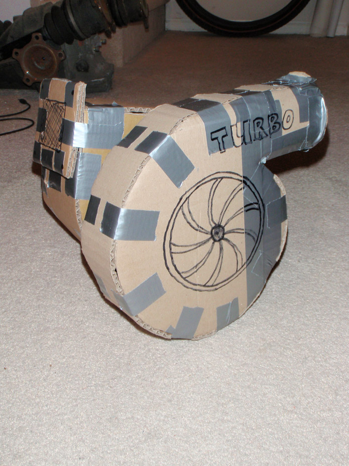
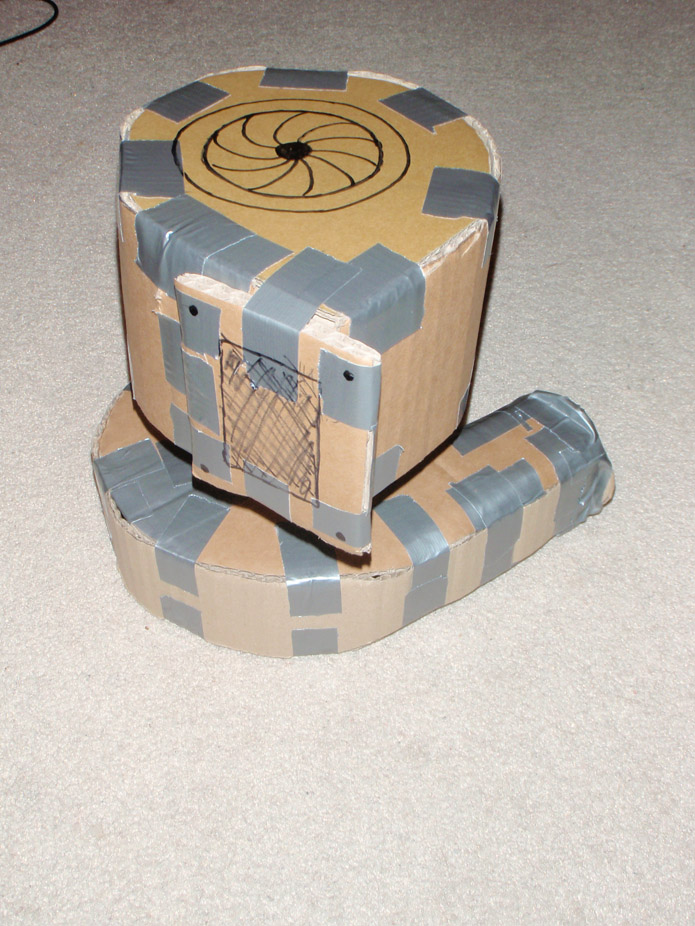
12-6-2010
I feel like an artist with a blank canvas...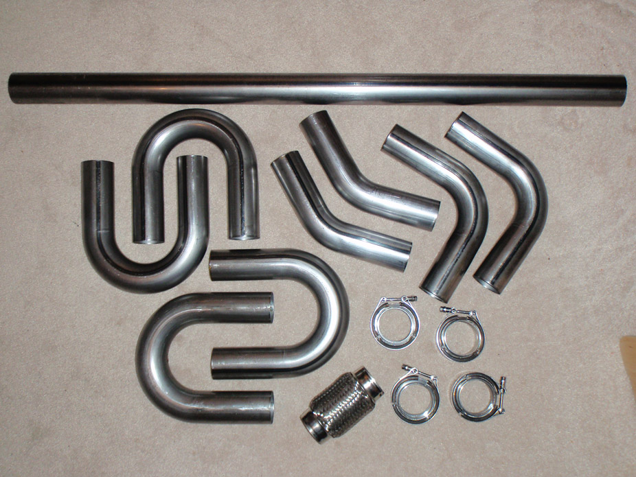
Virgin manifold metal!! Also as I was about to pay for the manifold eBay auction and I saw the seller also had this virgin LS3 waterpump. On a random impulse with the foggy memory of it being lower profile than the truck one, I just had to try it...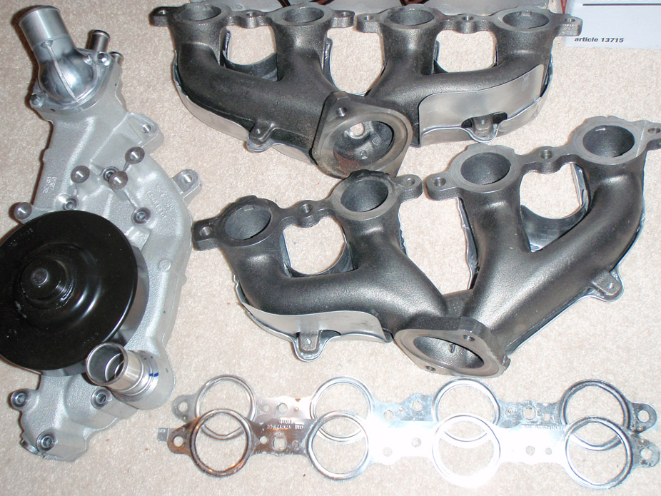
My memory served me correct, there's a nifty little O2 bung in the collector, and since the manifolds will be flipped upside down it'll be hidden
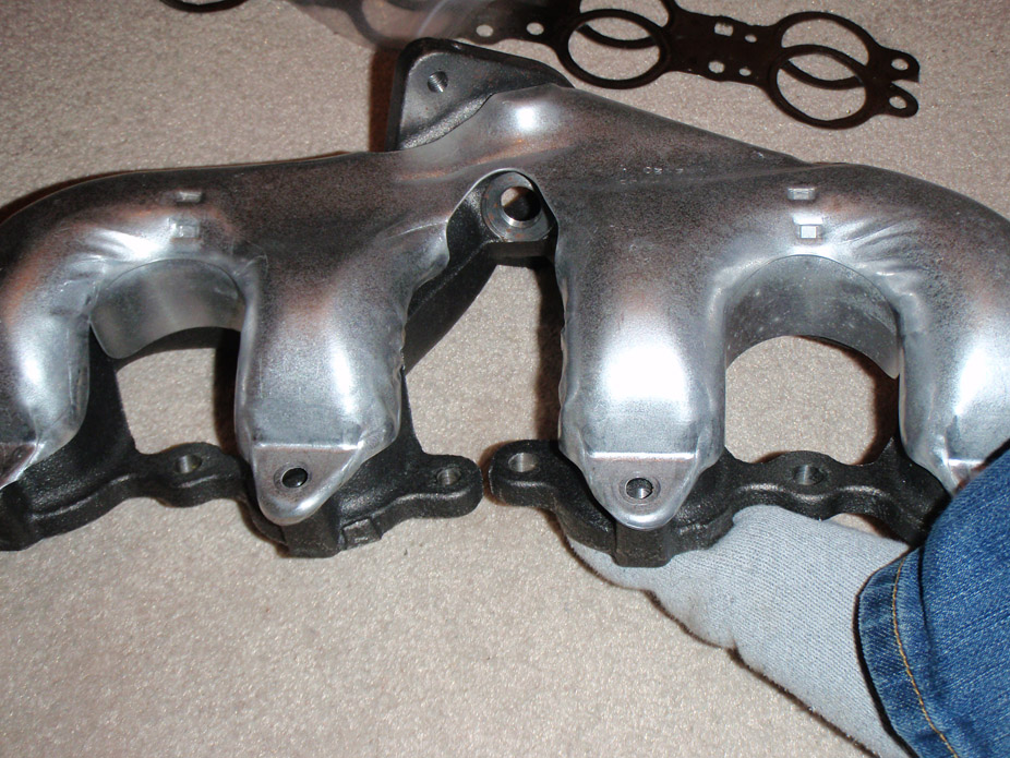
To give myself more room I though of possibly pulling these ports and tapping them, I'll have to see how much room I have/need for hotside piping..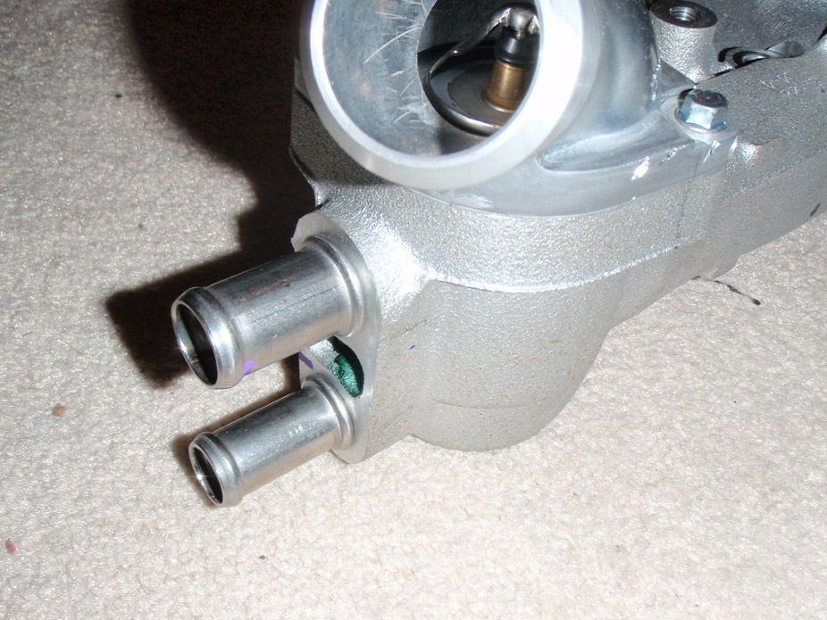
Also has this plugged port, not sure what for but could end up being a coolant return line for a water-cooled turbo!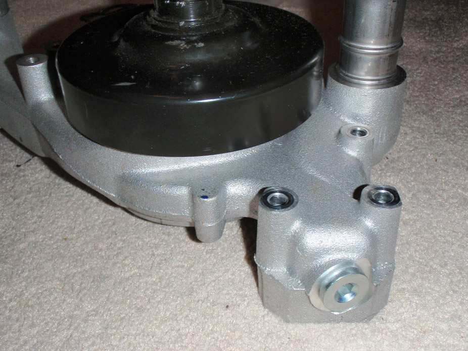
I essentially want to run this passenger side exhaust routing to get from the manifold to the turbo flange collector. The pipe looks like it'd come close to the waterpump return, so that was the main reason for trying the LS3 with its MUCH better return port location...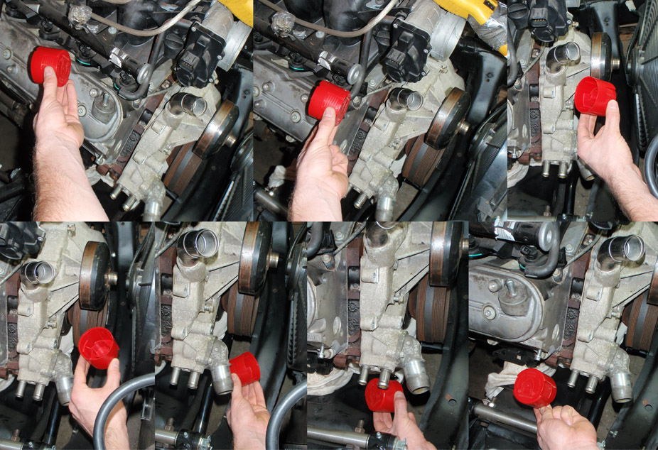
A comparison of the truck LQ4 waterpump (top) and LS3 waterpump (bottom)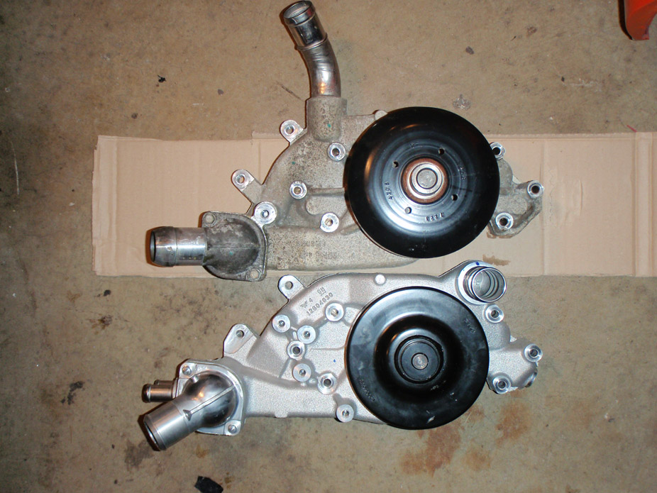
Again goes the old adage of Research, Research, Research! Crap, I did not realize it tucked it in this much, I remembered the pulley itself being lower-profile on the LS3 vs. truck yet still being in the same plane as the truck accessory pullies, but turns out I was thinking of LY6 NOT LQ4...
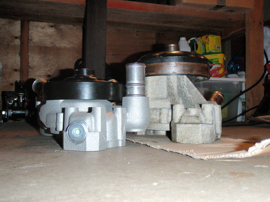
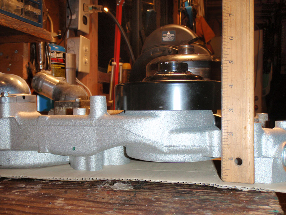
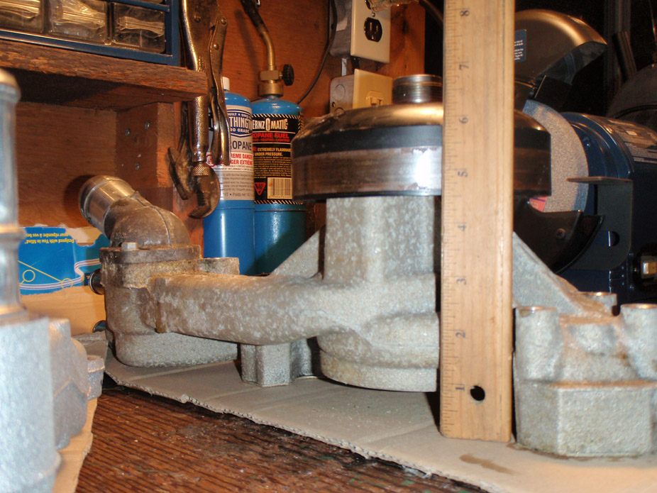
Well here is the reason I wanted lower profile, not a lot of room in this stupid short Nova engine bay!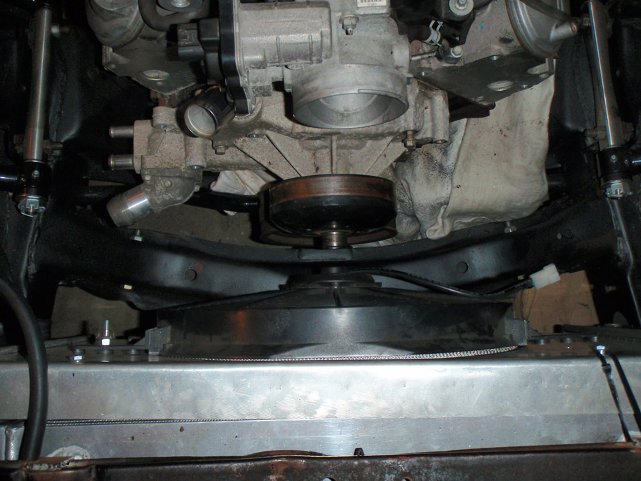
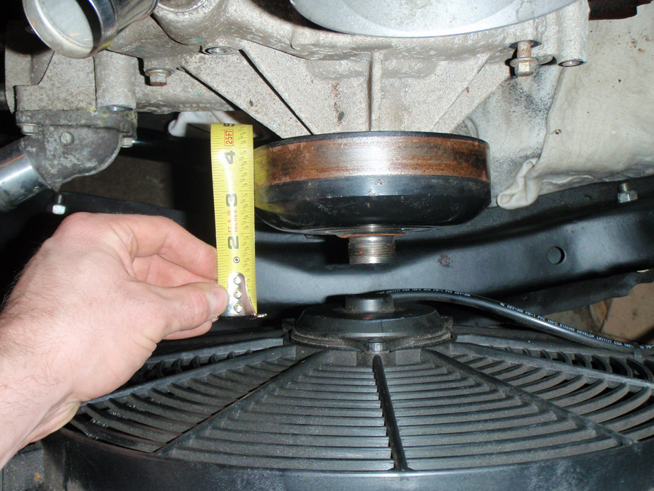
One reason I was thinking of moving the heater port from these hose barbs to an AN fitting at some angle, there's not a ton of room, the hoses would be tucking right against the upper control arm cross shaft and be right under the heat of the turbo...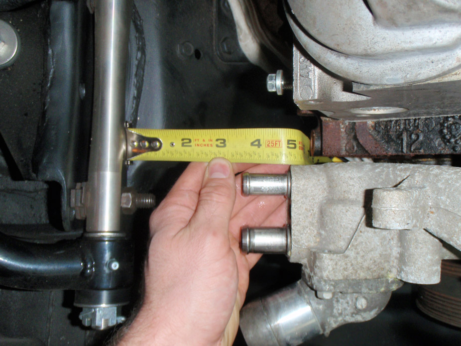
Well at least there's a tone more clearance...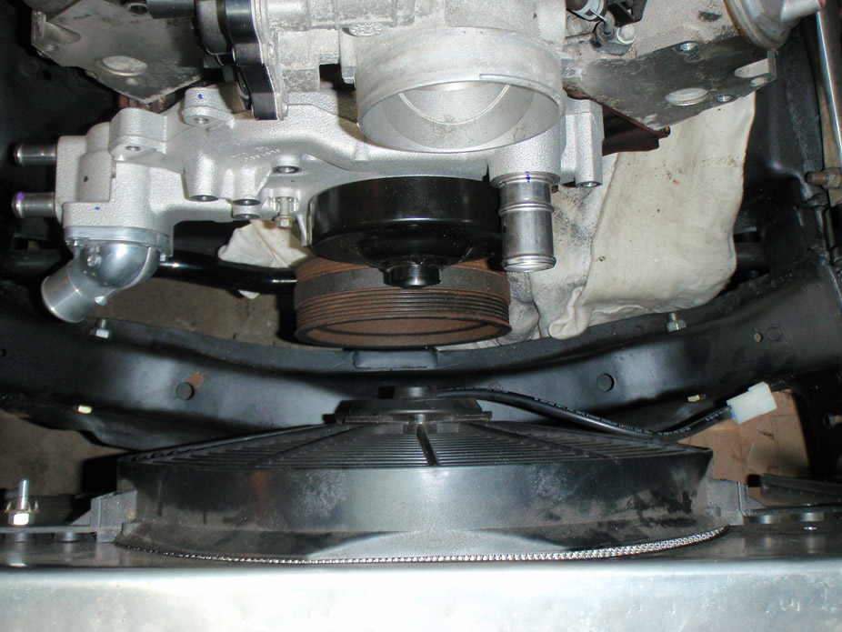
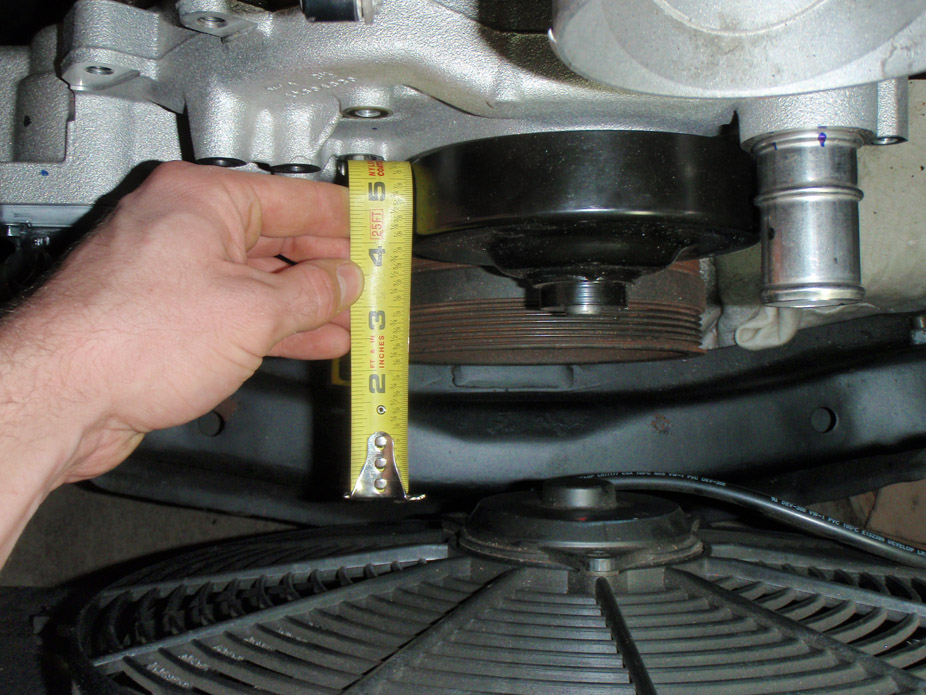
Except the LS3 water pump puts the heater hose ports even further outboard...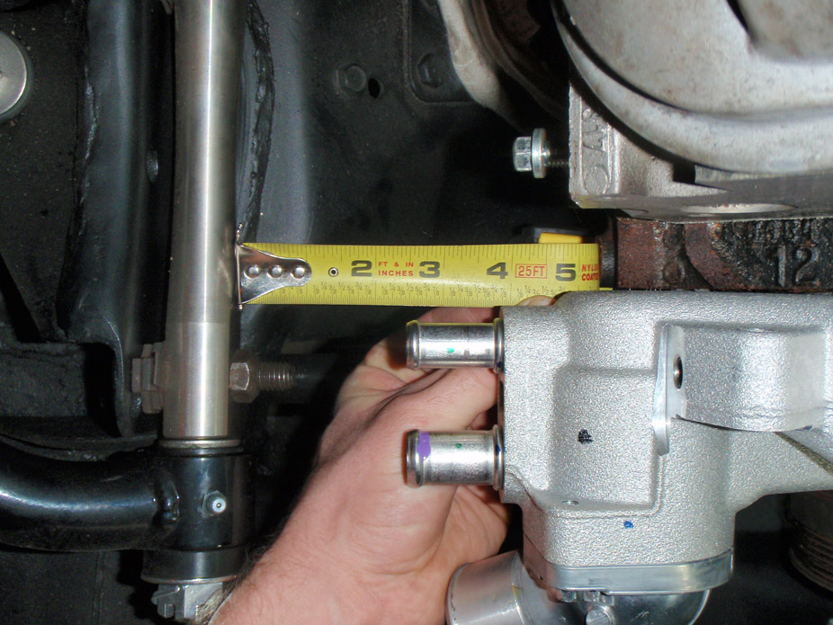
Easiest might be to make coolant-flow-thru spacers to space the waterpump forward the 1.5" offset difference, would let me keep the stock LQ4 accessory drive. Could have the heater hoses run across, up the inner fender, then tuck under the quarter panel. Also would allow more clearance for the passenger side exhaust pipe to tuck in behind the waterpump and merge to the turbo flange...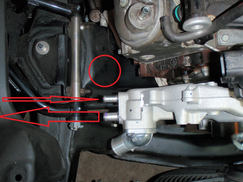
12-7-2010
Just over 24hours after them becoming new to me, they're not new anymore...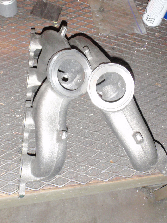
After running a couple test beds on the flange hole tabs I cut off, it seemed like the cast "iron" was pretty accepting of being welded cold, hopefully, so I got it all set up and ready for a couple test tacks without preheat (just decided to try out of curiosity)...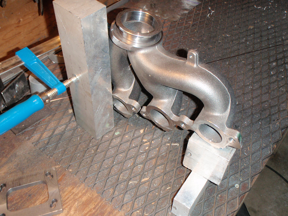
Heat was pretty good, was putting in about 75 amps without burning thru the vband flange, took my time working the area with the arc at 1/2 pedal before going all in and making a puddle for the filler. It doesn't look it in this picture but the manifold material was definitely molten as I was adding filler so there was for sure enough heat going into the cast iron...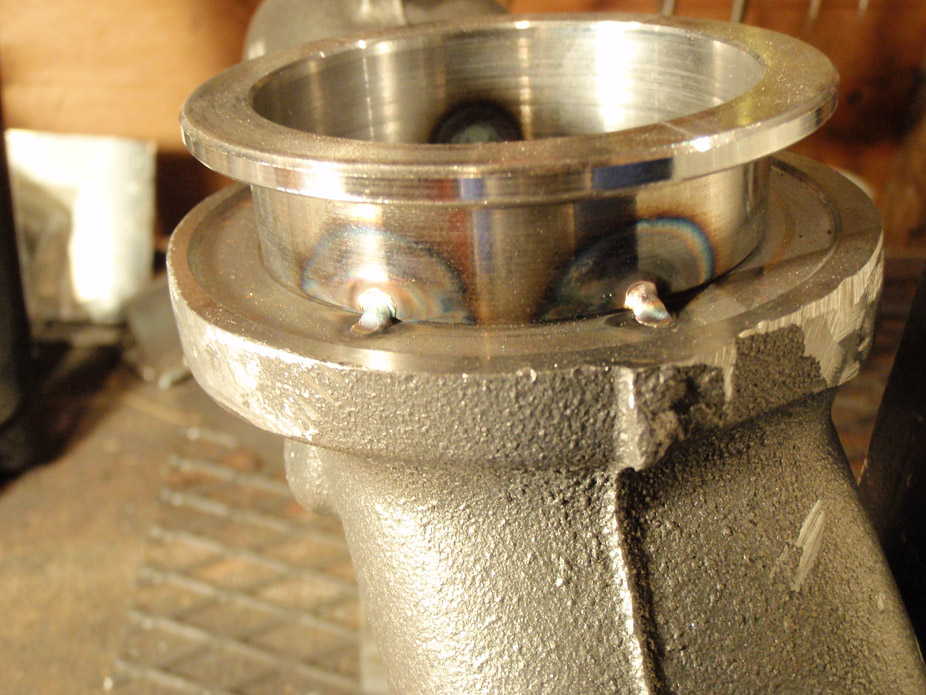
All of a sudden as I was taking a break I started hearing a ticking sound, and sure enough I inspect a tack weld on the opposite side of the flange to the two shown above...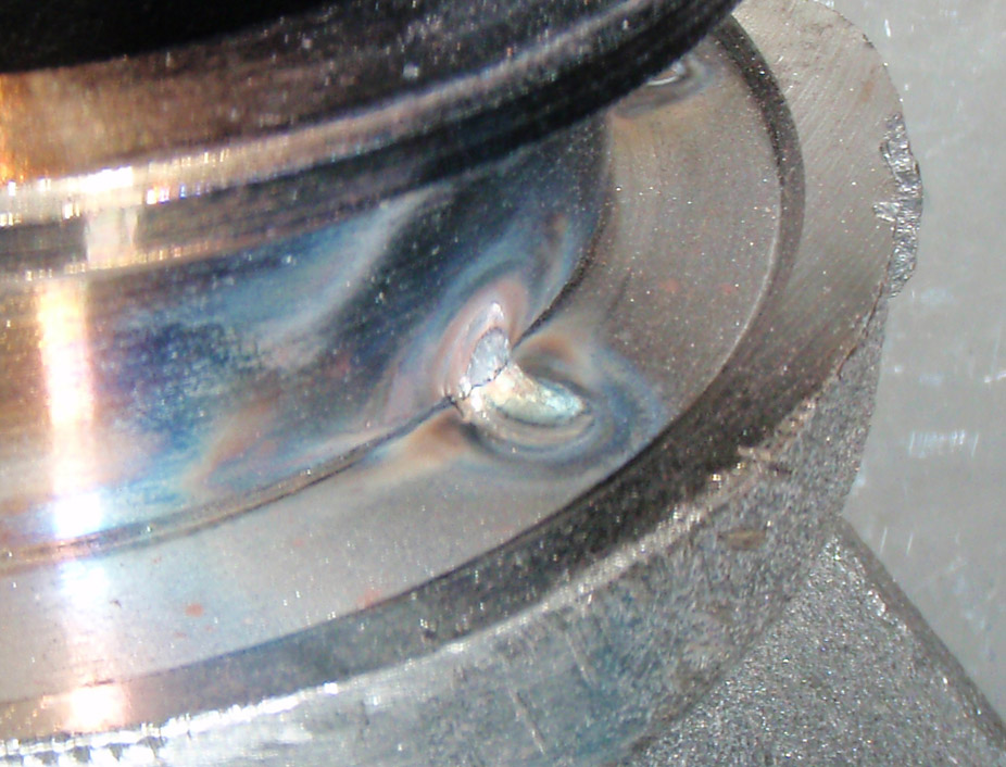
Guess I do need pre & post heat?
The vband flange was HOT but the manifold not so much, only in the area immediately around the tack... is it possible that the cast iron was soaking up all of the heat from that tack and causing it to cool too quickly = brittle tack?
I'm also thinking maybe the thermal expansion rates of the cast iron & steel are different enough to cause stress in the vband flange and break that tack? Although I would've thought that they'd both have similar cooling rates...
I tried tacking again but this time with pre & post heating with a butane torch for a couple minutes pre & post tack, it took longer to happen but sure enough the ticking sound started and I got a tack to crack.
Maybe shitty filler rod too? I don't even know the alloy of the rod, it was just generic "mild steel" filler that I picked up in a hurry at the local tool shed.
Any help/advice/tips/critisism would be greatly appreciated!!
12-11-2010
Did some baking this morning...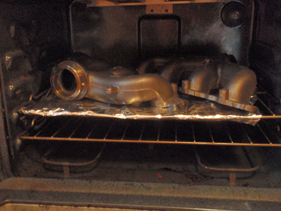
Recipe was:
1) Put manifolds in oven and from cold heat up to 450*F, hold for an hour
2) Took one manifold out, welded half the vband, put back in oven, took other manifold out, did half bead too. Went back to first one, finished, put back in oven, finished second one, put back in oven.
3) Let both fully welded manifolds sit in oven for ~15minutes
4) Turned heat down to about 300, let sit for ~15min
5) Turned heat down to about 150 (lowest oven would go), let sit for ~15min
6) Turned oven off, let everything inside cool down until I could touch, took about an hour.
Result: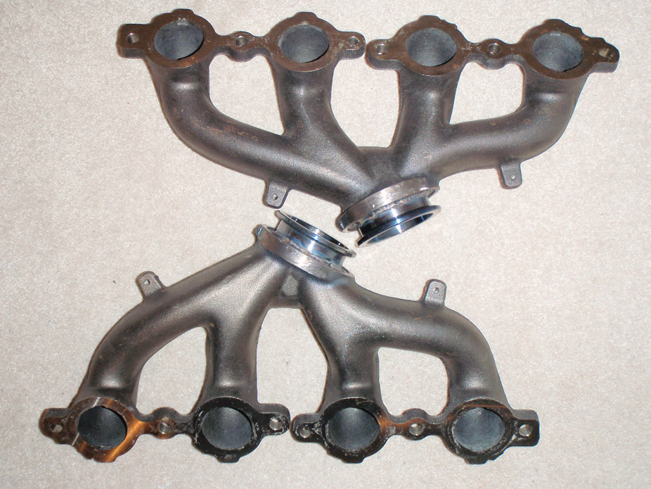
Used regular ER70S mild steel filler rod, didn't heat with a torch or anything during the breaks between beads, just tried to do as quick as possible... bead quality shows that Also it was awkward as hell trying to change angles for different parts while not resting either hand on the manifold:
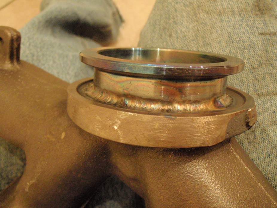
Not once did I hear any pinging sounds, however I was putting in about 100 amps had post flow set to 10 seconds which I think cooled the beads down a bit too much because the end points of two beads had small cracks, but everything else looked fine. Will have to carefully pre & post torch those 2 areas and quickly puddle them to fill the cracks.
12-15-2010
About 3 hours of "measure six times cut once" and I have the driver side tacked together...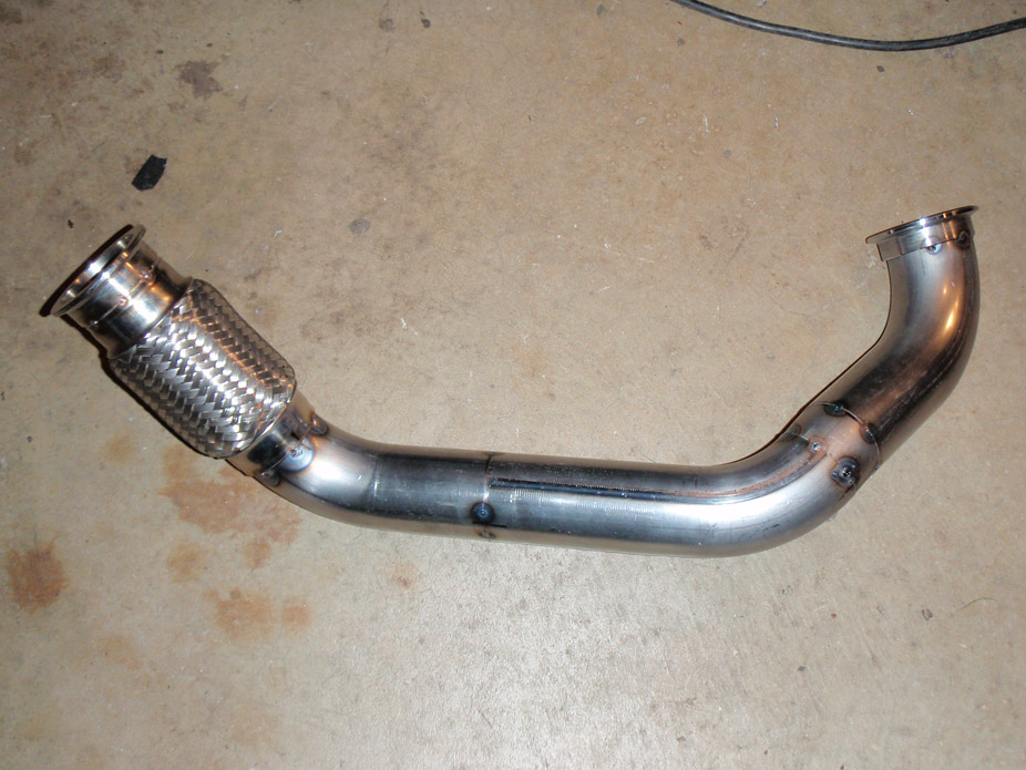
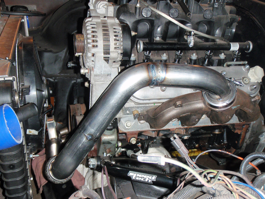
There's oodles of clearance around everything, 2" from PS pump cap, 3/4" from PS pump pulley, 1" from crank pulley, and 2" from the radiator...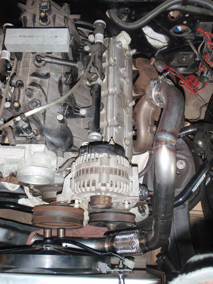
Tentative planning on how driver's side will come up to merge, as drawn in one of my previous post's pics...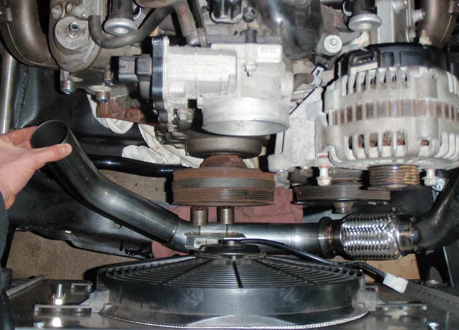
12-19-2010
I wanted to throw the LQ4 alternator/PS pump bracket back on to see what work would be needed to make it work with the L99 waterpump, and surprisingly not much was needed...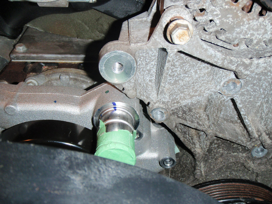
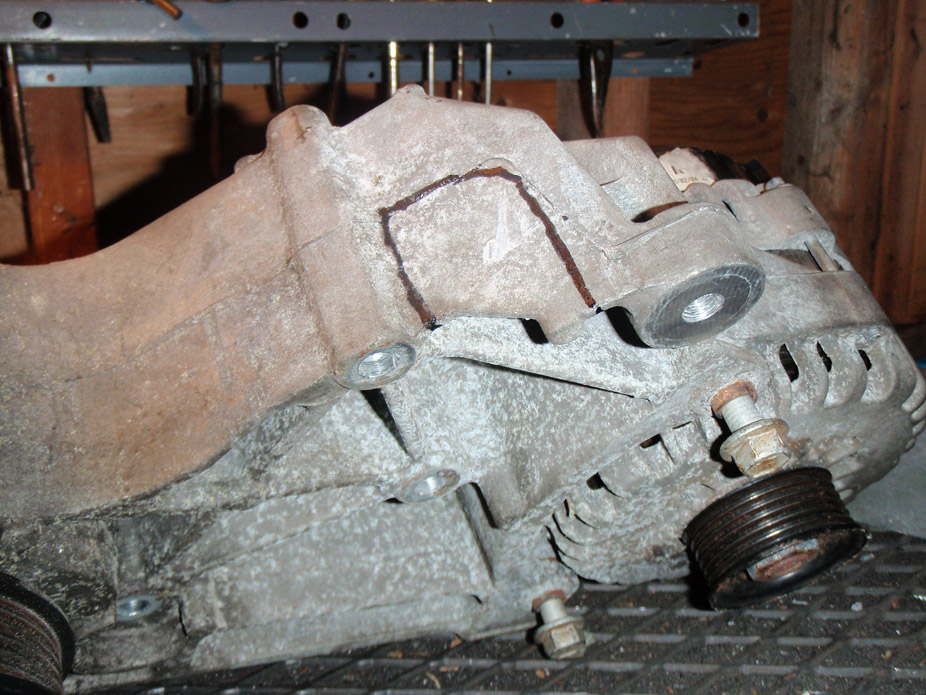
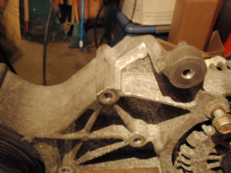
Skimmed a bit off the waterpump housing too...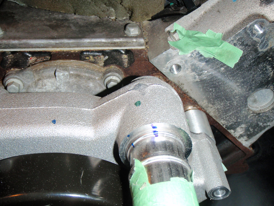
Not the cleanest cuts but it'll all be pretty hidden...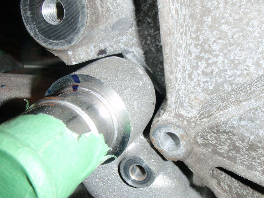
12-20-2010
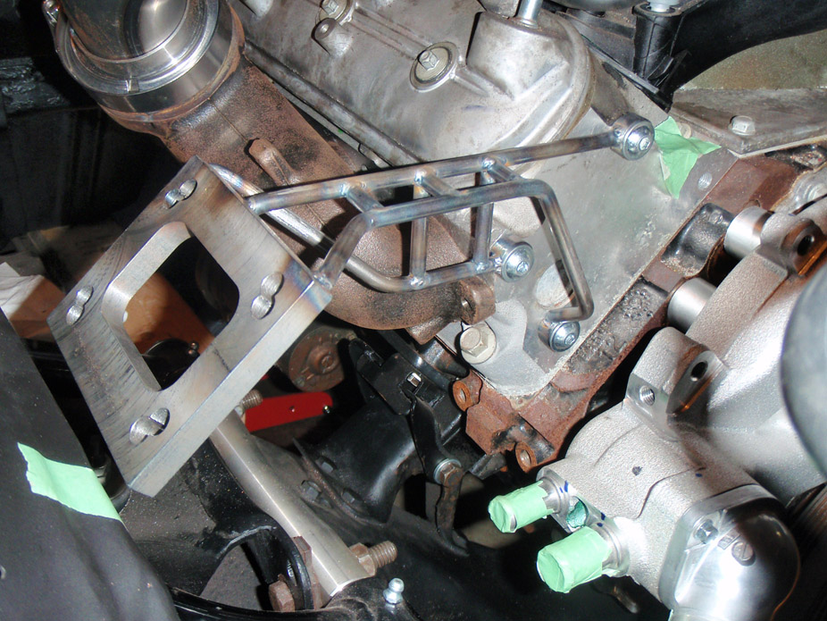
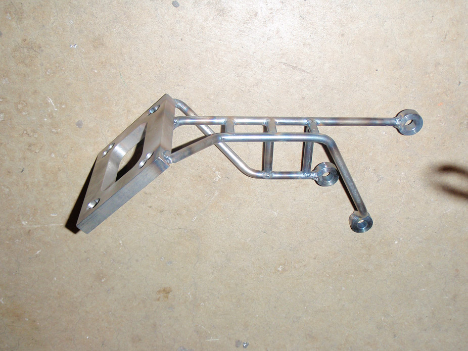
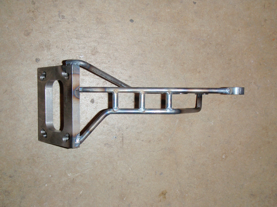
Made a turbo brace. Even with using filler rod to test the bends, it got pretty confusing. I didn't just want a couple rods at random angles supporting the turbo, tried to make the supports look uniform & industrial, to just blend in...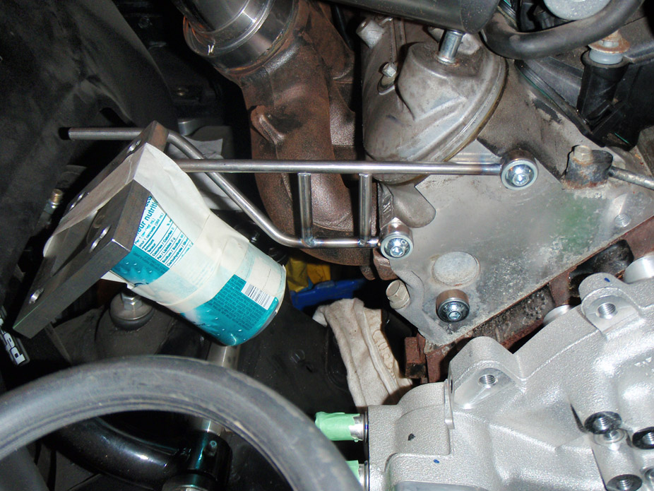
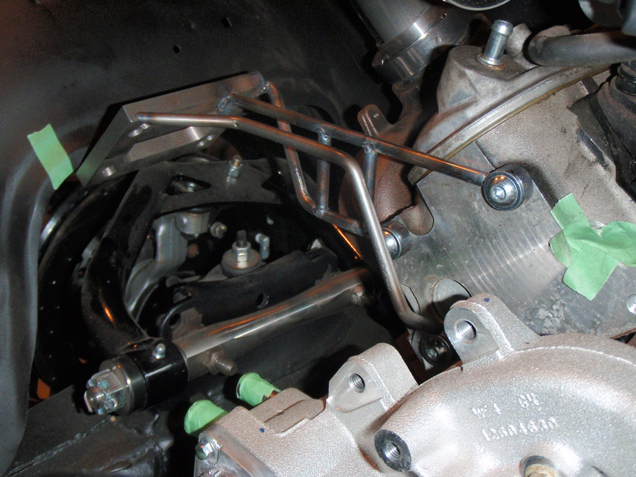
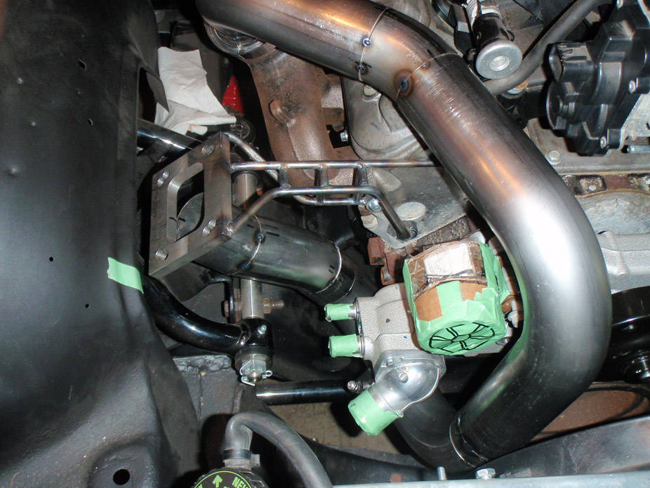
Worked on the passenger side hot pipe, bending over the passenger side valve cover, forward in front of hte waterpump, down in front of the waterpump, under to back behind the pump, then up and sideways, behind the pump and into the merge for the turbo flange...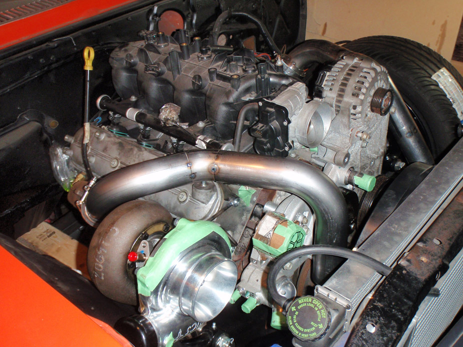
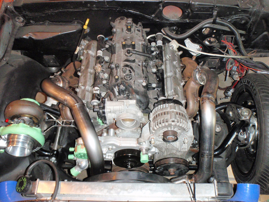
I never would've thought it but electrical tape is great for holding tubes together for mockup...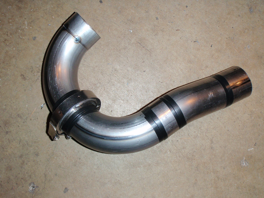
Resulting passenger side up to flange, without miters for the merge with the driver's side...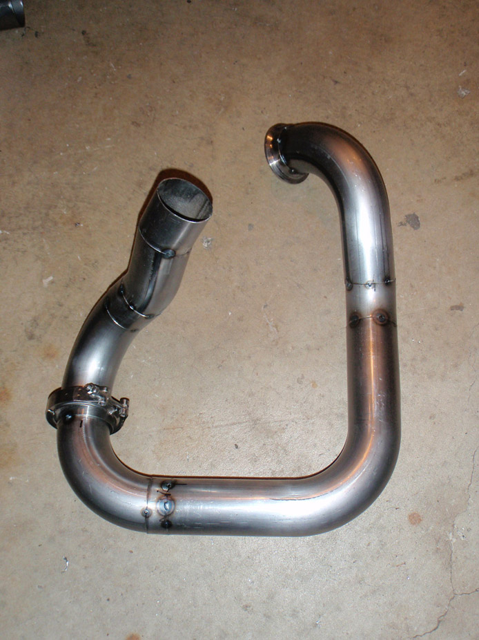
Good view of how wonky/wobbly it looks with all the bends...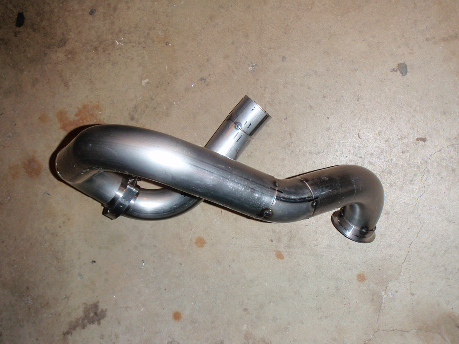
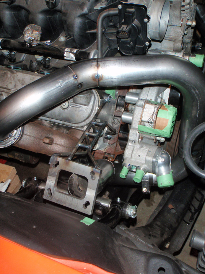
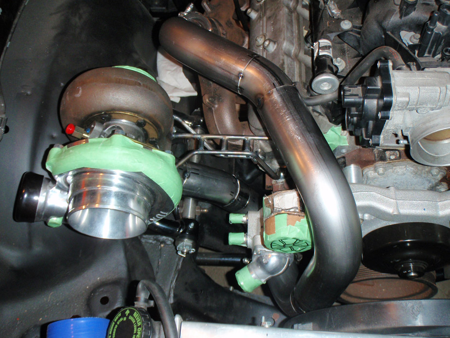
I put the turbo there for two main reasons...
1) to make the turbine outlet clear the passenger side manifold as much as possible (but a couple bends will still be needed to maneuver around the manifold's vband)
2) to make more room for the two pipes to come up and merge behind the waterpump and beside the block. With the turbo any closer to the block the pipes would have massive interference with the front corner of the passenger side exhaustmanifold, so with the turbo a bit further outwards I can bend the pipes down & out to clear underneath the front of that pass. manifold.
Reqarding the strength of the brace, it's made out of 1/4" drill rod, and it doesn't even flinch when the turbo is placed on it. With turbo on there, I definitely whacked it and tried to move it around, but I ended up shifting the engine on its mounts (!!!) and rolling the car back/forth a bit without doing anything to the brace... I think it should be strong enough 
1-14-2011
Not too much progress to report. Back in school for my final term so away from the car, still whipped up some waterpump spacers in the school shop though...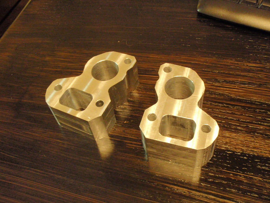
This is the last stage that I left the hot side piping at, have to complete the merge and about an extra foot of pipe then it'll be done!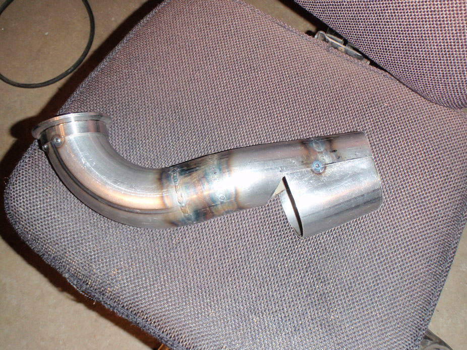
1-25-2011
Hah as much as I'd LOVE to own a surface grinder, I simply wouldn't have the room in the garage to store it nor the money to have it shipped... sorry!
Took a weekend trip back to work on the car, got little done, but is still progress...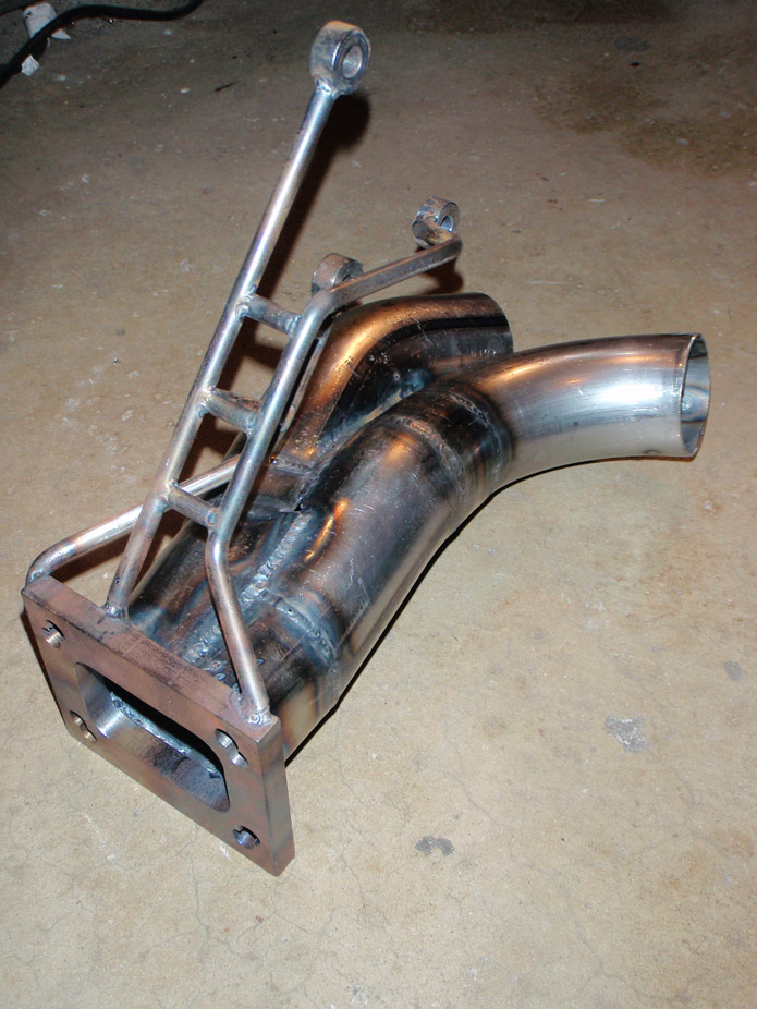
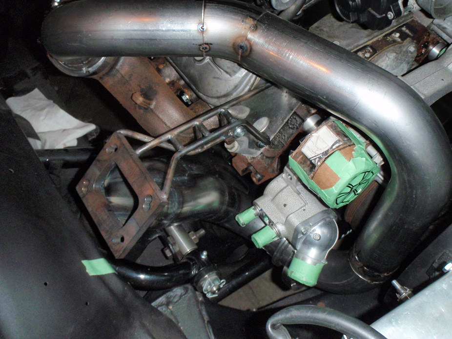
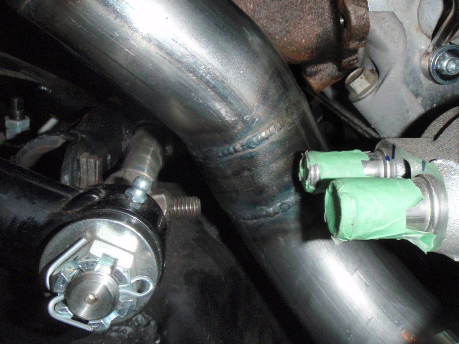
There is a minimum of a finger-width clearance next to the closest areas: block, a-arm cross shaft bolt, and waterpump heater outlets...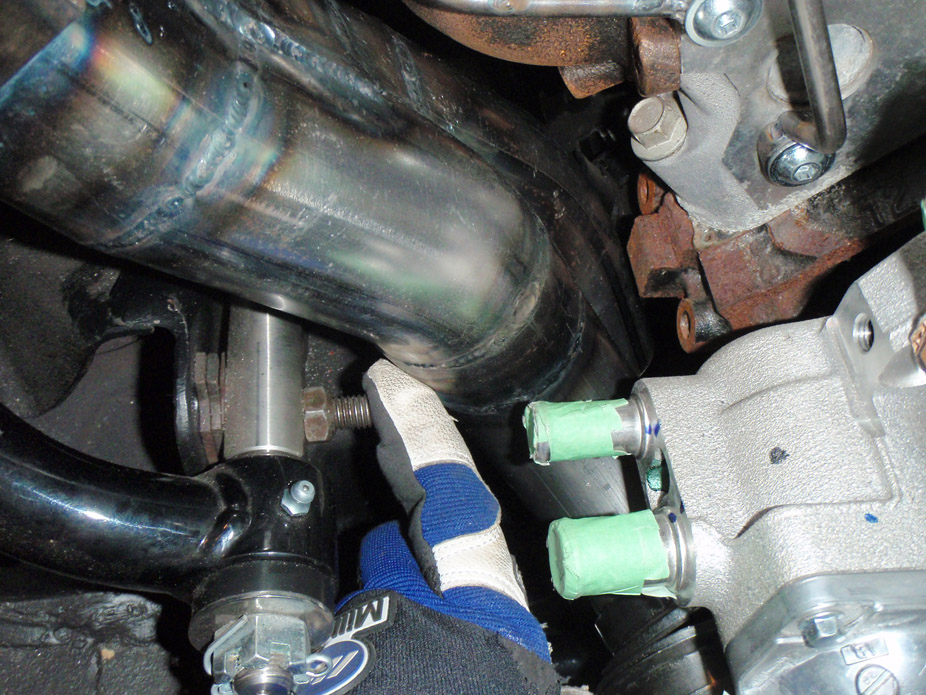
Mark! You're back!!
I definitely thought of giving as much room around the a-arm cross shaft bolts as possible, and I've prettymuch pushed it to the max. There is enough room to completely remove the nut (see finger-clearance pcis) as well as tons of room in front to slip a wrench in there... I actually thoguht ahead!
Definintely going to resurface the turbo flange. My turbo came with a stainless steel gasket, will probably include that too.
As for the manifolds, they came with new stamped stainless gaskets as well, so unsure of whether or not I'll need to surface those.
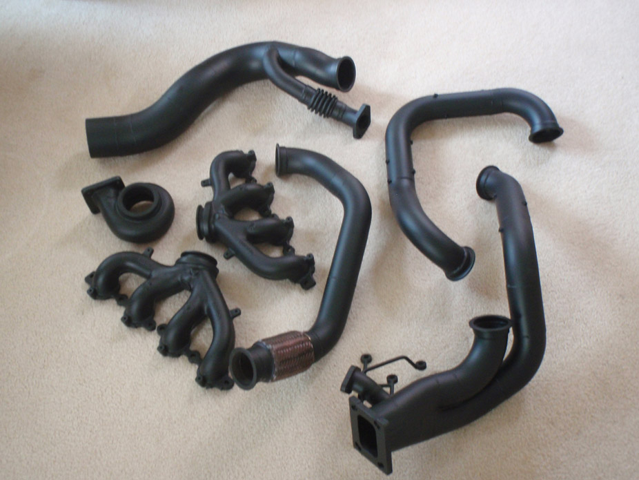
The entire hotside will come off for blasting and ceramic coating (funny I have a school project now on ceramic coatings inside engines) once they're fully welded and mocked up to triple-check clearance/placement of everything.
Coil pack relocation will happen. The LS3 manifolds when flipped upside down actually give tons of spark plug clearance, especially since the plugs angle down as they exit the heads. I plan on using the bolt holes that fasten the coilpacks to the valvecovers to bolt them longitudinally (front to back) in a compact manner, then bolted to some braces supporting them to the block. Get them as low and far from hot pipe heat as possible. Most likely will require custom length plug cables though. I've seen this done a few times already and it looks compact & hidden.
Might use those insulator covers for the spark plug wires, but defintely will use them for the heater hoses coming into the waterpump there. Also on the fence about a turbo blanket or a coating on the hotside...
2-7-2011
Marktainium... No this is an aftermarket Turbonetics unit, I ditched the VGT Holset sadly because I realized it just wouldn't be close to effecient at the low boost I wanted on a 6.0L gas V8.
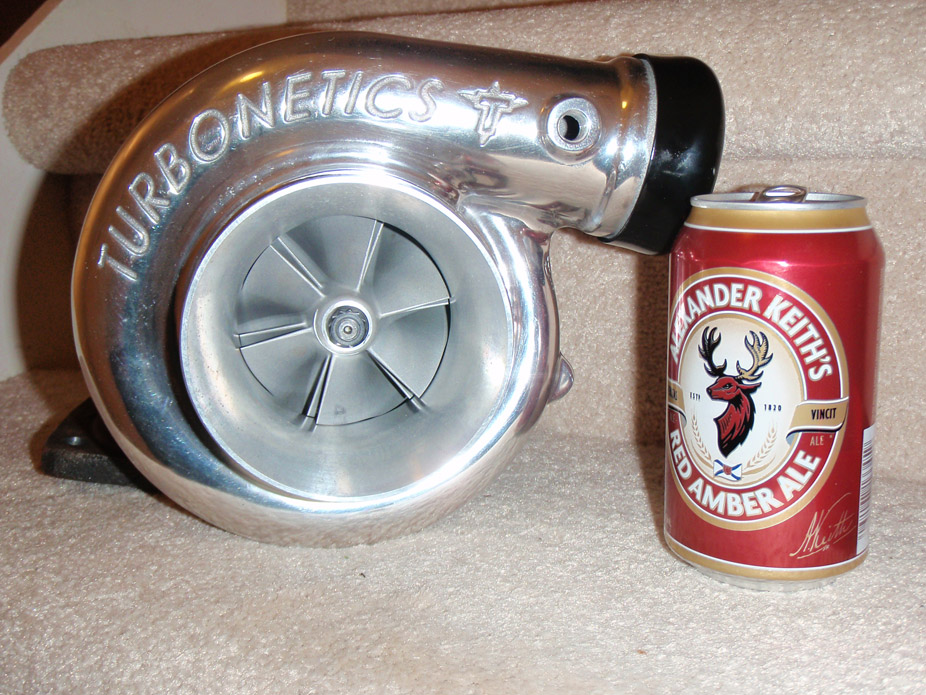
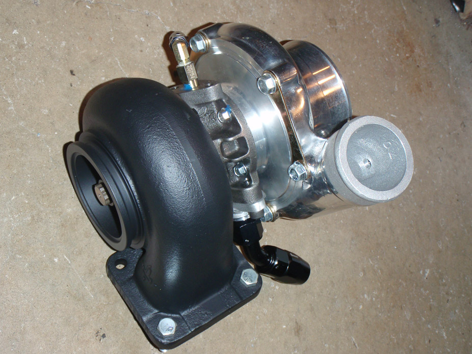
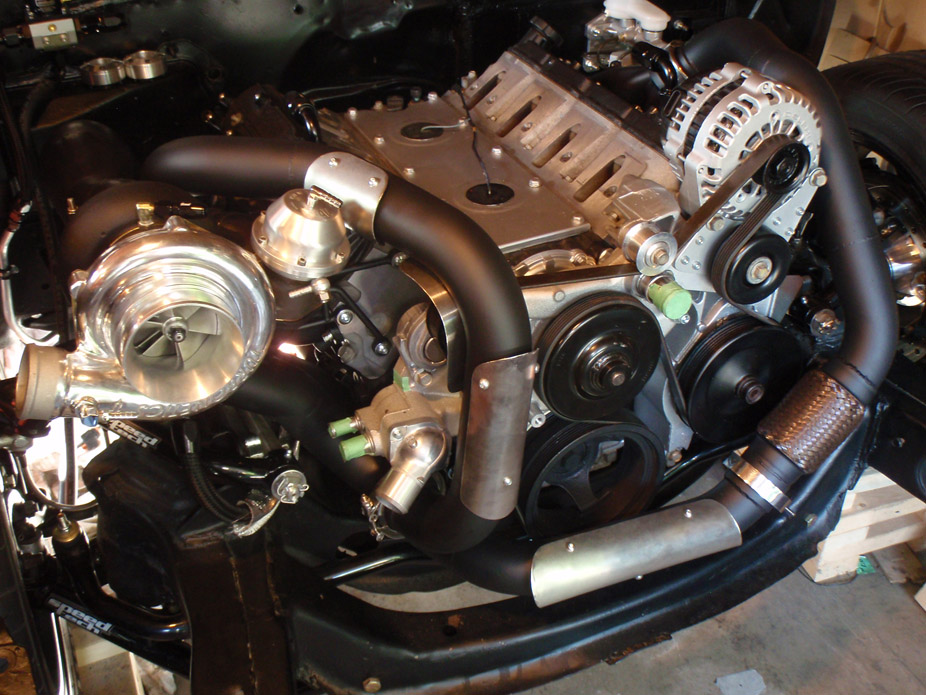
Turbonetics TC76 with F1 (68mm) wheel and 0.96 A/R hot side...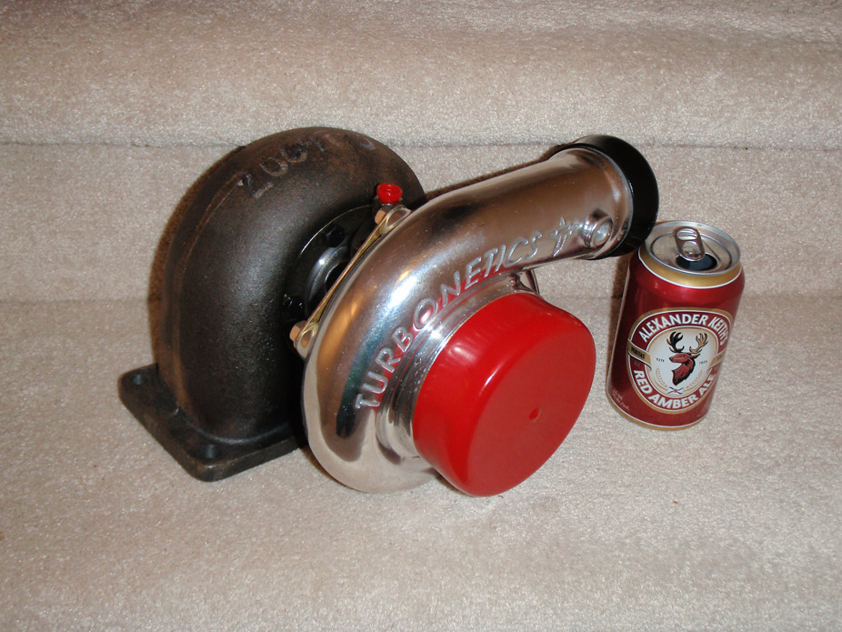
Much practice makes results that I kinda like!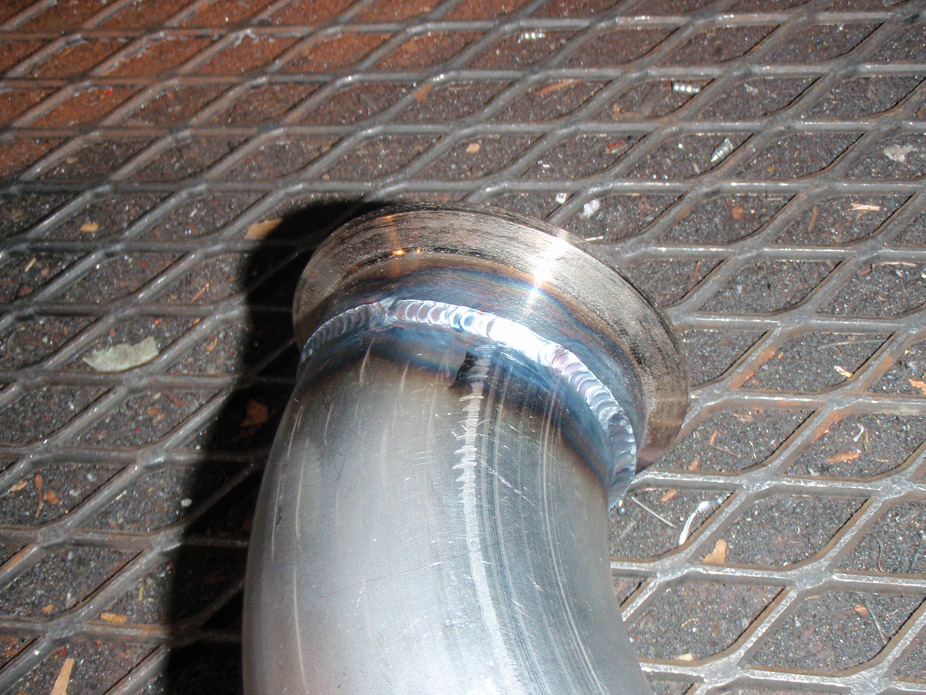
Merge pipe all tacked together, SO MUCH time in this one...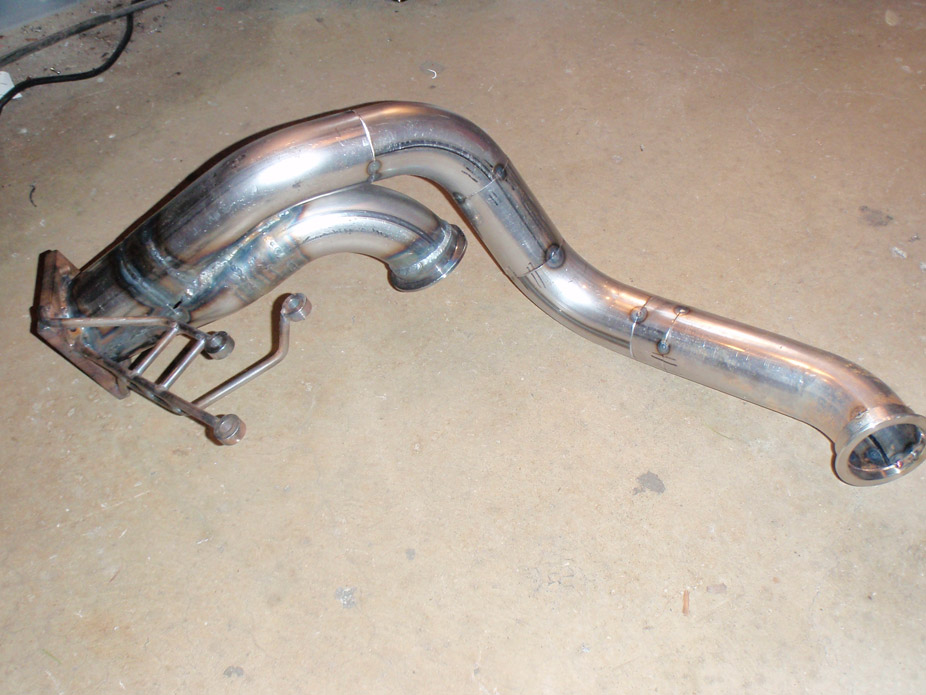
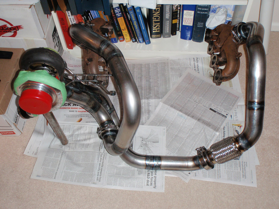
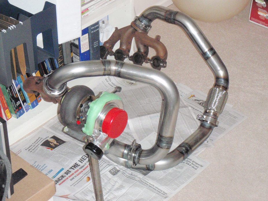
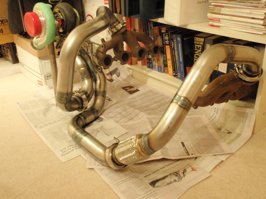
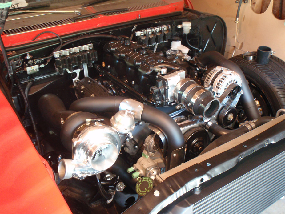
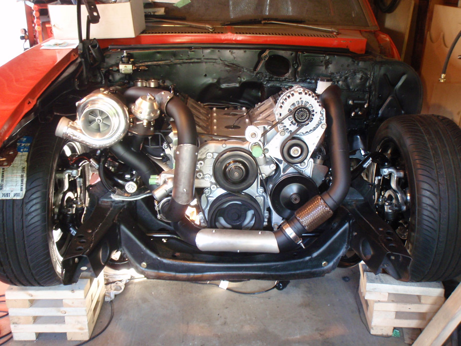
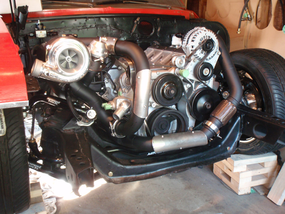
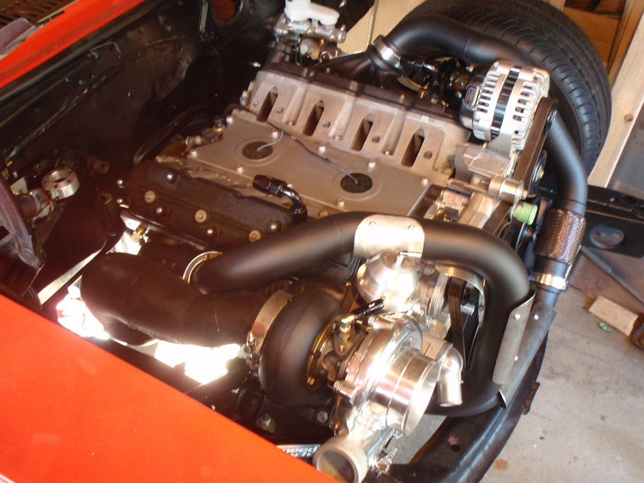
Custom LQ4 Nova turbo hot side piping fully welded (sans wastegate flange). LOTS of time but I think the results speak for themselves, great clearance around everything and no mods to the engine bay required to fit the setup... I'm happy!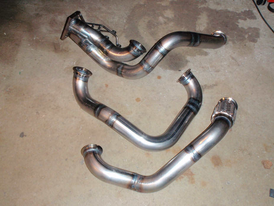
2-7-2011
Thanks for the compliments!
Yes I did do a lot of my own research on the turbo stuff, including calculating the pressure ratio & mass flow of air and plotted that on the Turbonetics TC76 compressor map, and it looked like it'd work. I then asked the very open "what turbo should I use??" question to a handful of the turbo guys on this forum as well the Turbonetics tech line, and all said that for my power requirements and usage plan, a TC76 or T76 with a 0.81 or preferrably a .96 A/R ratio. It was nice to have my own research backed up with their expertise.
Stats:
- 3200 lb street car
- 550 rwhp through stock T56, with 6-7psi and boost by 2500 rpm
- 100% driver car, not going to launch this thing hard off the line, only rolling "starts"
- good mid- to low-rpm boost response but without always being in it, don't want to burn through too much gas
Setup so far:
- Turbonetics TC76 with F1 wheel, 0.96 A/R, BNIB off this forum - $1000
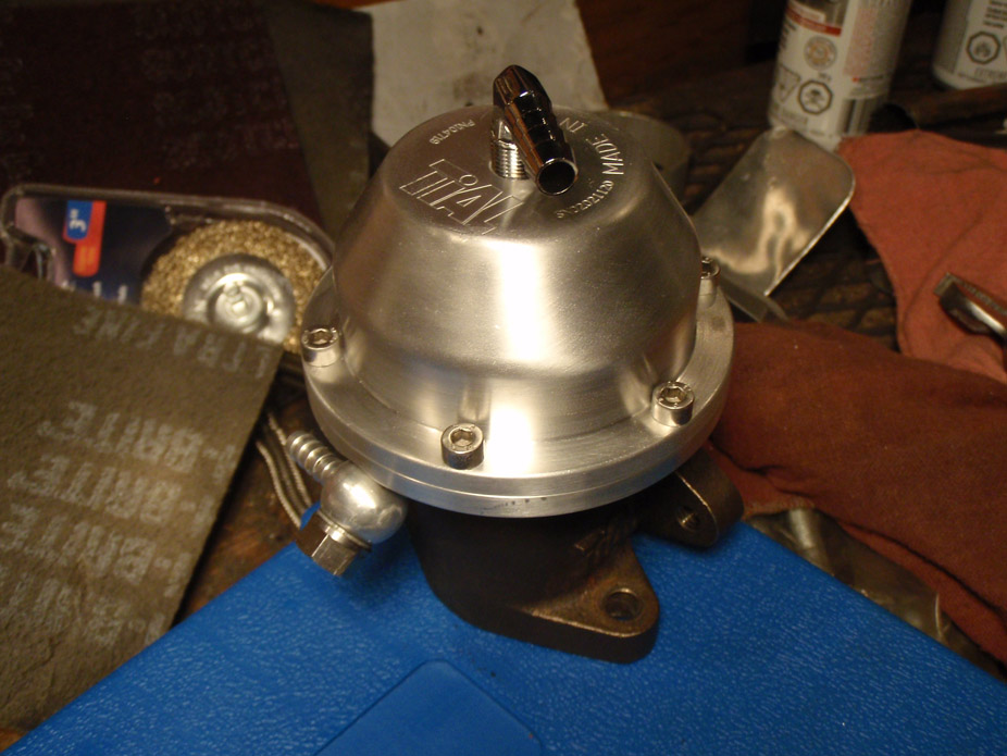
- Tial 38mm wastegate - $220 off Craigslist
- GReddy 40mm blow off vale - $120 off Craigslist
- LS3 Camaro exhaust manifolds, new - $80 off eBay
- Columbia Mandrel Bends Ultimate Builder Kit (2.5" mild steel) - $114
- Columbia Mandrel Bends V-Bands (x4) - $120
- Columbia Mandrel Bends 2.5" stainless flex pipe - $20
- LS3 Corvette fuel injectors, 42lb-hr - $220 off this forum
- Adjustable boost-referenced FPR - ~$200, still haven't gotten yet
- generic 24"x12"x3" intercooler - $60 off Craigslist
- still need to get aluminum piping and mild steel downpipe and y-piping - ~$300
Total: ~$2600 so far (including stuff that I still need to get in near future)
2-18-2011
When I was running stock GM stuff, I had 5x4.75" (hub side) to 5x4.5" (wheel side) spacers for the front and rear wheels.
Since the front Wilwood hubs have both patterns drilled in them, and they supposedly move the hub faces outboard 0.75", then I'm just going to use slip-on spacers on long studs in the 5x4.5" bolt pattern for the front, and then do the same in the rear (get some stronger aftermarket axles that either come with 5x4.5" pattern, or have them drilled for them).
It took me a long time to find wheels I liked for my price range, so I'm gonna try as hard as I can to keep these Axis Penta wheels on the car... plus the gunmetal grey centers match my racing stripes perfectly
2-28-2011
1 step forward, 17 steps back. Out come the body bushings for more lowness, before I can start making the final trans tunnel...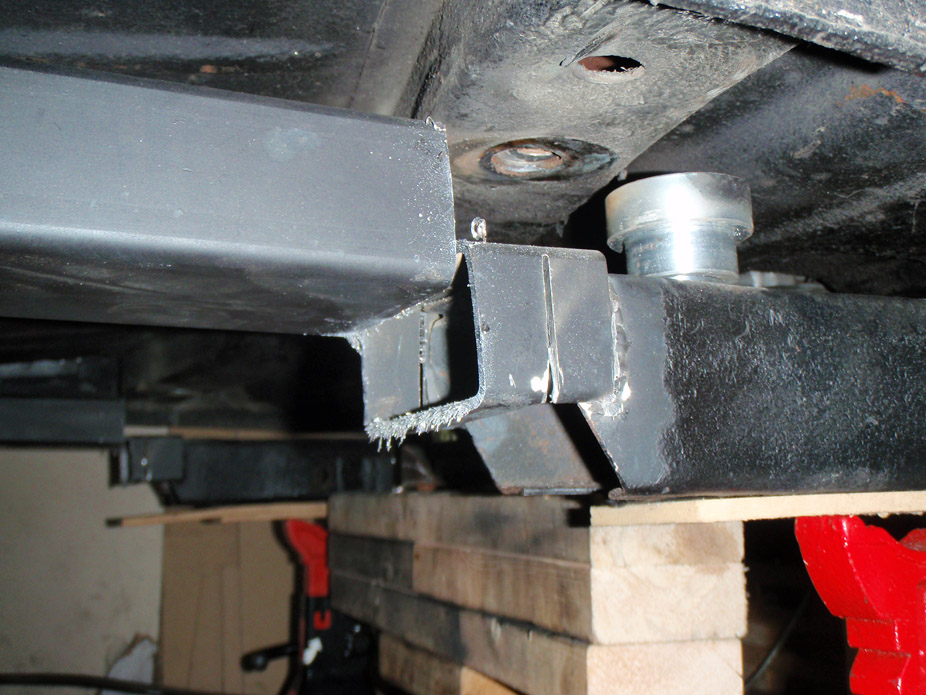
Another step back, so much more cutting...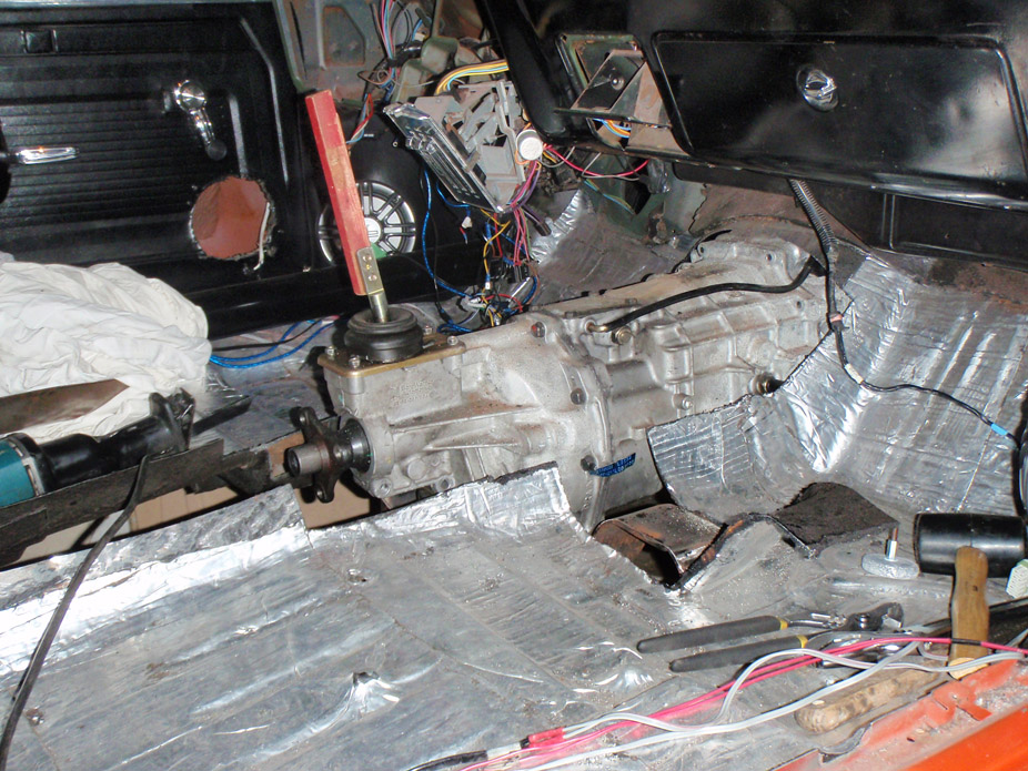
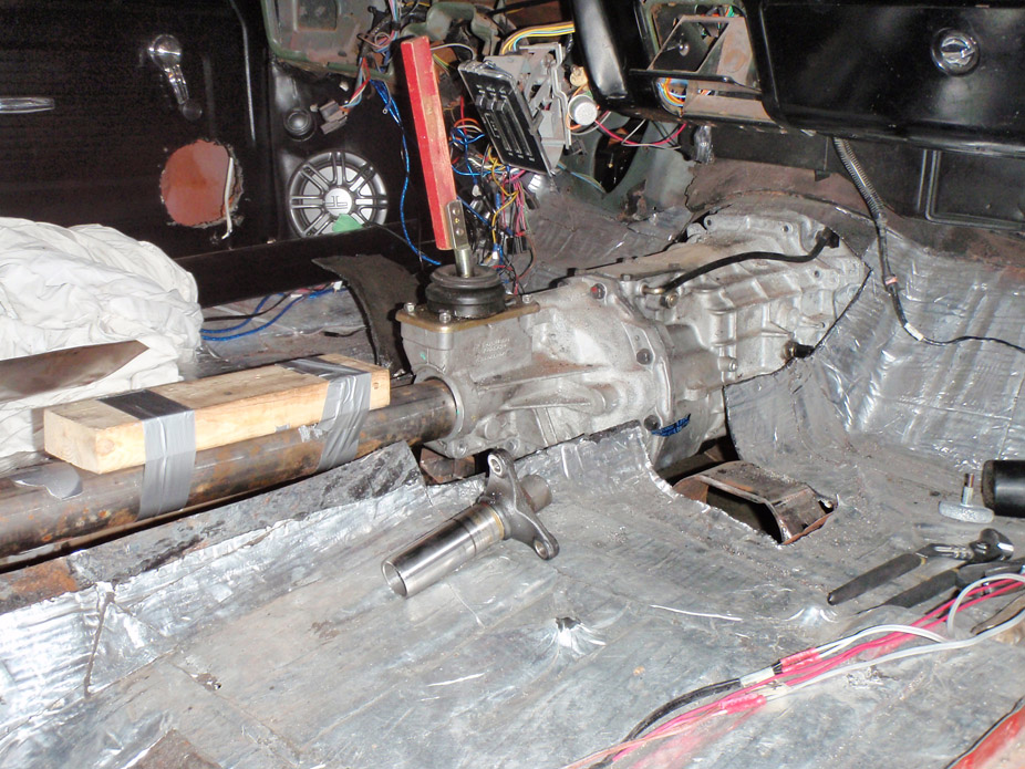
240SX pedal assembly that I got for practically nothing. I like that each pedal is essentially a self-contained unit that bolts directly to the firewall/respective master cylinder...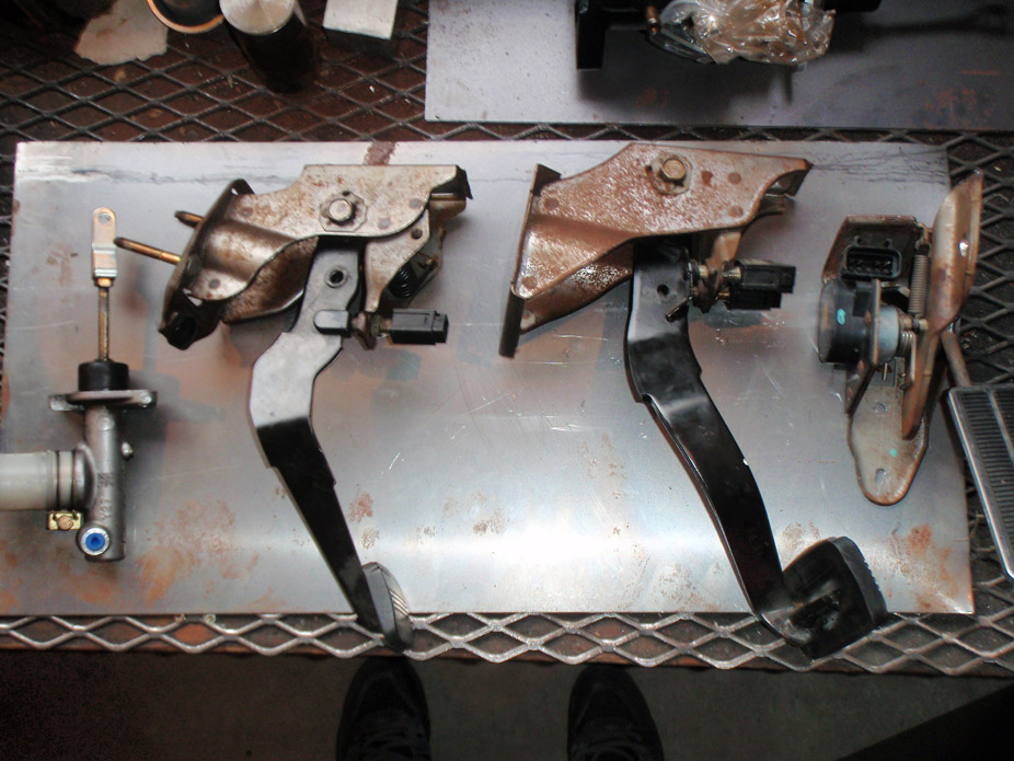
Mocked stuff up. Would like to use a stock 240SX clutch master cylinder but have yet to do the research/math to see if it'll have the right pressure and volume...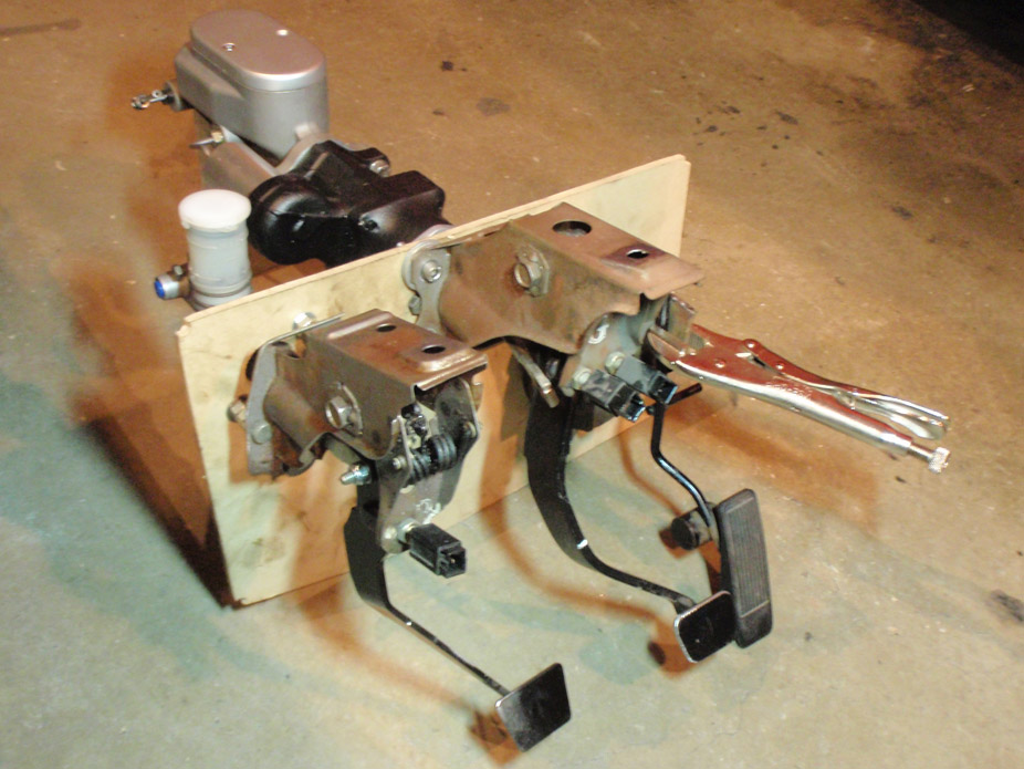
And just some cool shots of mostly final tubing. Still have to weld in a wastegate flange...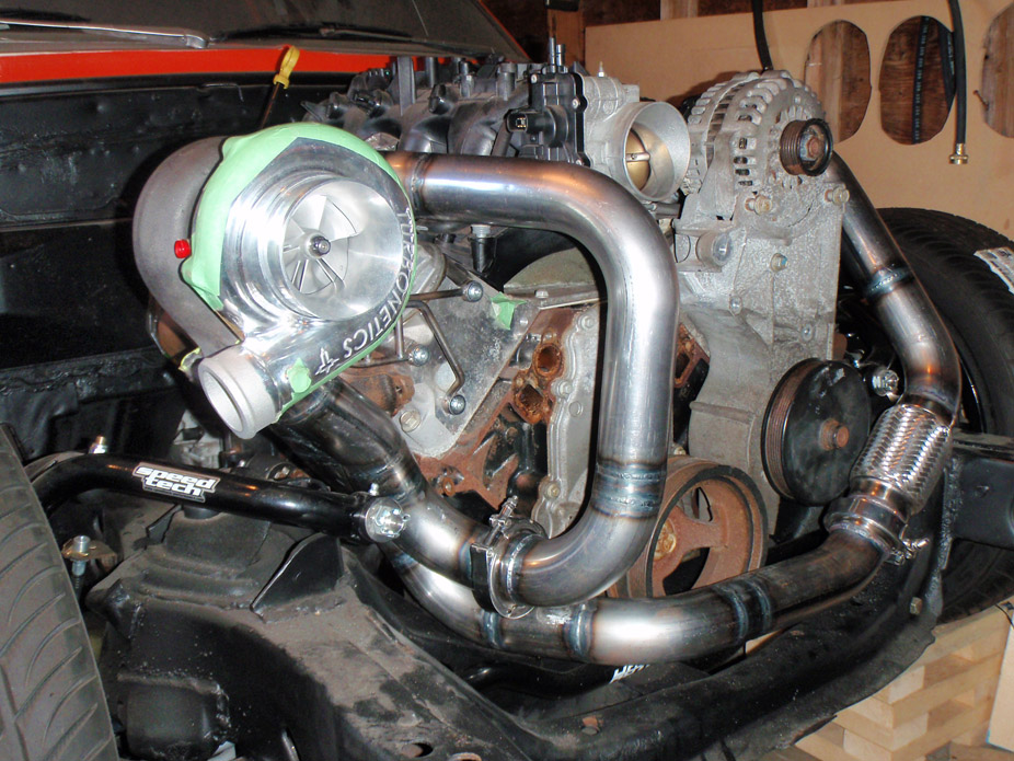
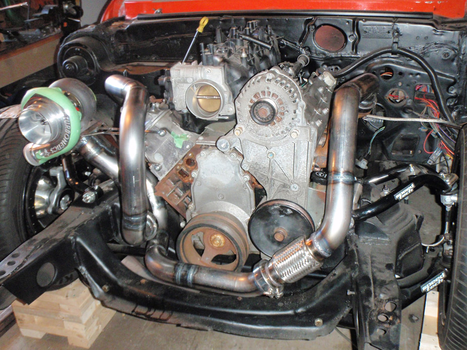
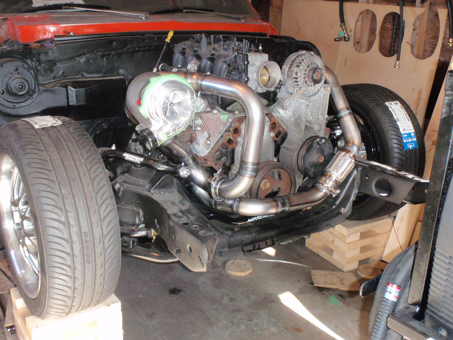
Ghetto trans tunnel fab...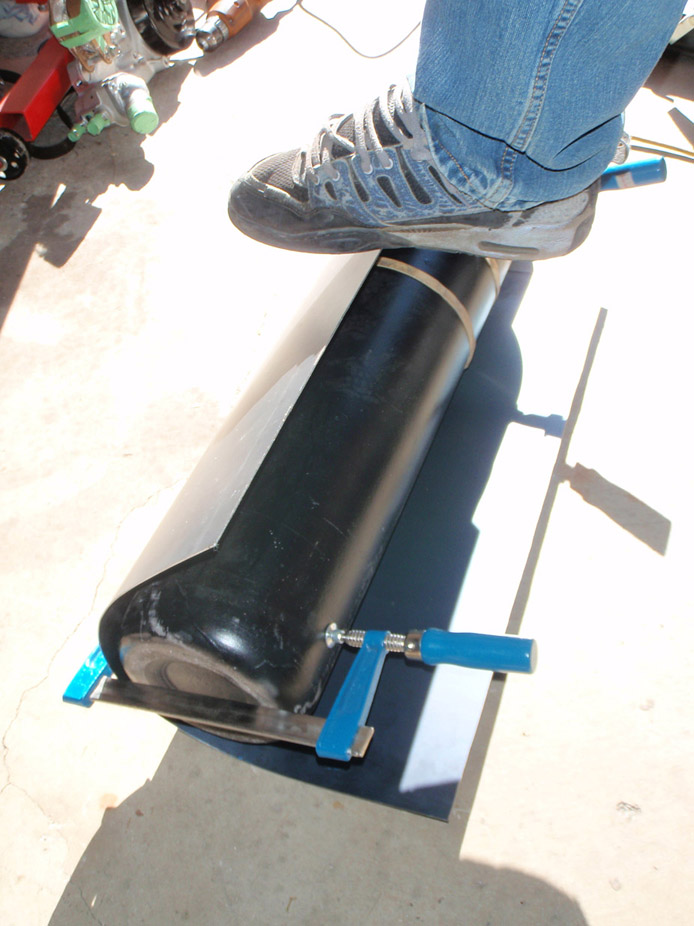
Shifter boot podium/pod thingy...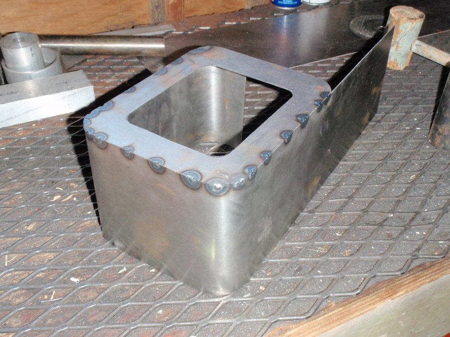
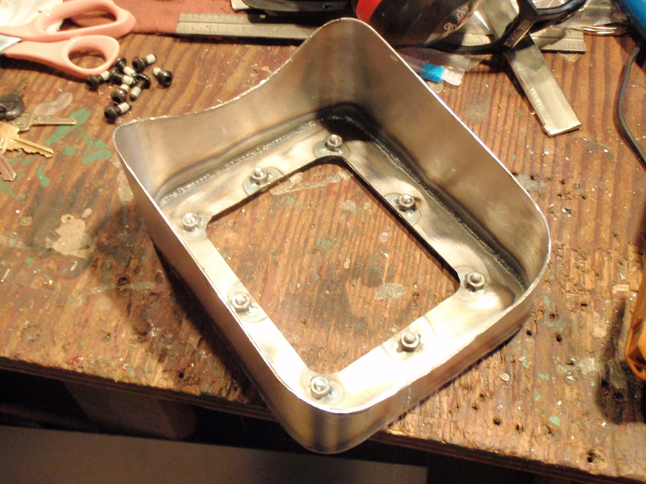
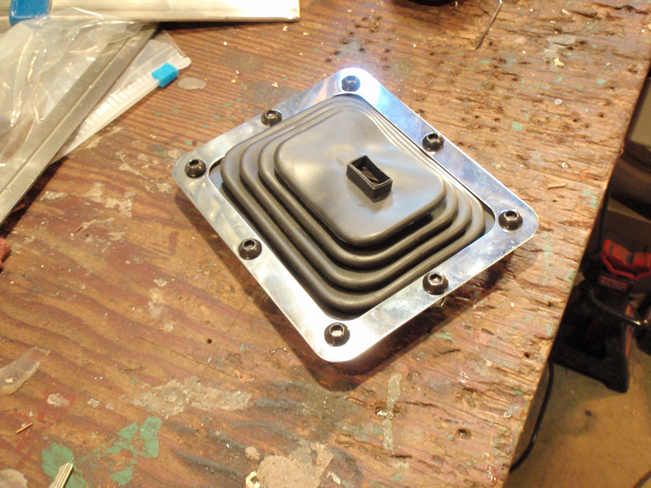
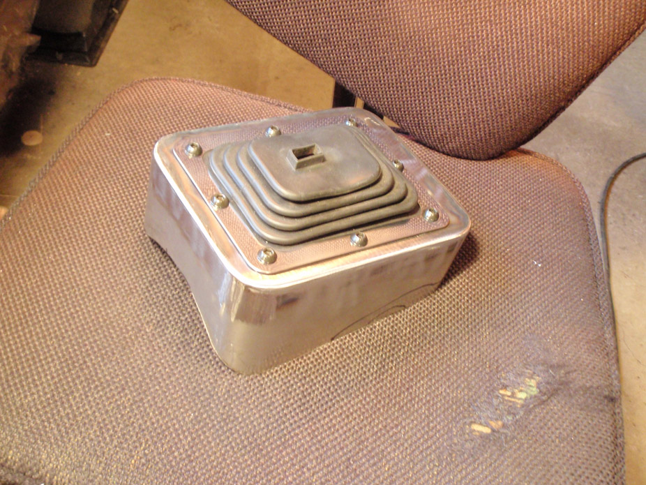
Result is something I'm happy with, nice medium of modern but industrial/functional/racey...
3-21-2011
Bored at school and procrastinating through my last 2 weeks of class ever... now it's time to think of fuel system.
I'm really on the fence between a sumped/baffled in-tank setup or a transfer pump/transfer tank setup...
a) 2 pumps, transfer tank setup:
-low-pressure, high-flow internal or external pump for gas tank
-modify current 3/8" gas tank fuel sender to except some 1/2" setup, possibly even more mods if in-tank pump used
-need to make transfer tank for engine bay
-need new high-flow, high-pressure pump for engine bay (Walbro 255 likely wont be enough)
-more fittings and lines for engine bay = $$$
b) 1 pump - in tank setup:
-new high-pressure, high-flow single in-tank pump
-new gas tank
-need to make baffle setup
-need to make or buy/modify fuel pump holder inside tank
Already have 1/2" supply and 3/8" return aluminum lines for under the car, both would be needed regardless of setup with an adjustable FPR in the engine bay.
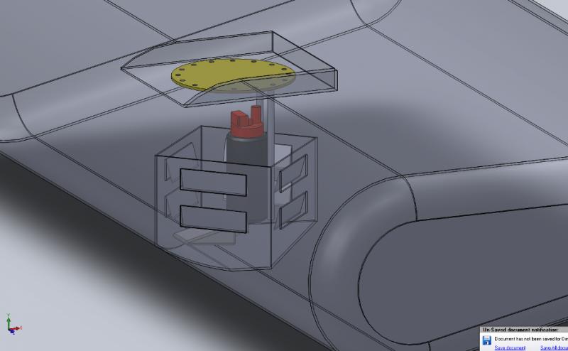
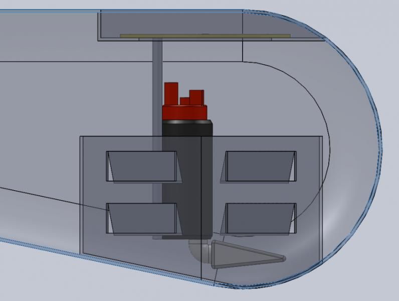
A design I've been thinking of a long, long time since I first swapped in the LQ4...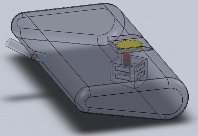
3-22-2011
I was originally toying with the idea of making my own stainless tank, but I'd be really unsure of the quality of my welds to feel safe about it on a gas tank.
When I say "two pumps", I mean a setup of a low-pressure transfer pump in the rear of the car transferring gas to a smaller transfer tank in the engine bay, where a secondary high-pressure pump would be used to supply to the fuel rails.
A "one pump" setup would just be a high-pressure pump/pumps in the rear of the car, either internal or external, pumping gas directly to the fuel rail.
By my calcs, using the legit Fuel Calculations on RCEng.com, for a slightly-higher-than-what-I-want crank hp...
- 650 crank hp
- 0.80 injector duty cycle
- 56psi fuel pressure (worst-case low pressure requiring highest flow from injectors)
- resulting injector flow = 58 lb/hr
Total injector flow = 58 * 8 = 464 lb/hr
(464 lb/hr) / 6 = 77.33 gph
(77.33 gph) * 3.7849 = 292.7 lph (from conversion site
Thinking about using the Aeromotive in-tank 340lph pump... quite reasonably priced I think at $169...
New Aeromotive 340in tank pump - LS1TECH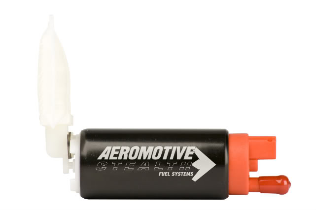
At 56psi that pump works right at 300lph at 13.5V, however I remmber my system running around 14.4V, so this should work out well for my slightly-lower-than-caluclated power goal of 550 hp at the crank.
So I'm leaning towards purchasing a new tank (~$125 CDN), welding in some baffling/sump for the pump, and using that Aeromotive pump and skipping the whole transfer pump and engine bay tank setup.
Procrastinating can really be productive sometimes, believe it or not.
I'm really leaning towards a single in-tank pump setup. Doing lots of reading, the Aeromotive Stealth 340 pump listed above does seem like the most economical choice for my power and driving goals.
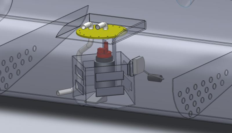
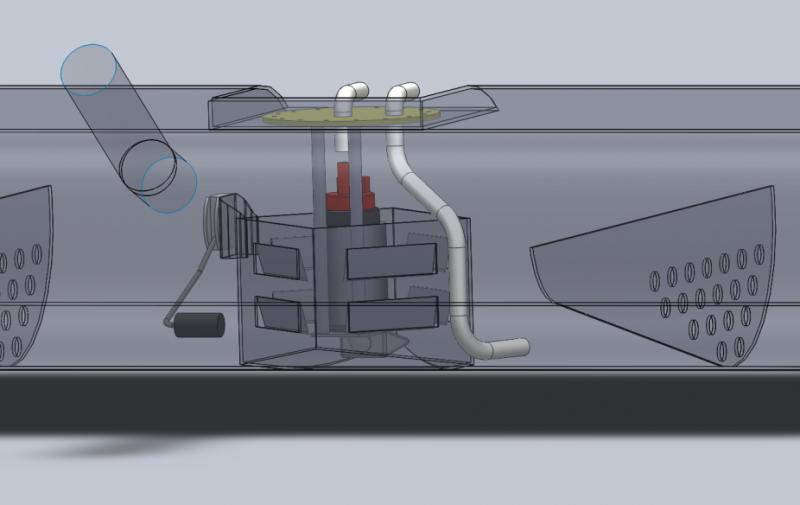
Next choice, how crazy to get when modifying a a virgin-steel new gas tank? The holed baffles are quite unlikely due to wanting to keep the access hold in the tank fairly small, but might be possible if done before the patch is welded in for the initial cutout for the access hole recess. Still leaning heavily towards the trap-door setup shown and updated below...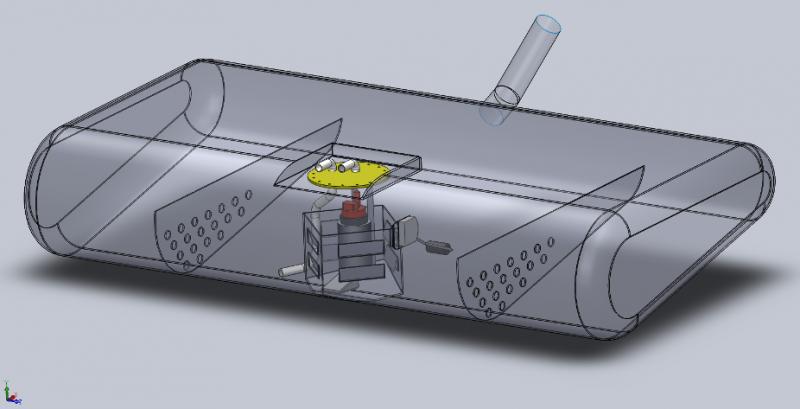
4-15-2011
Couple of updates:
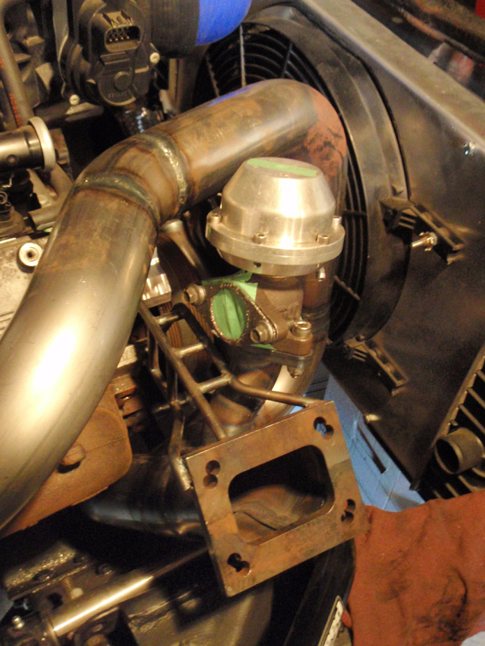
First, got the wastegate welded on, so hot side is officially finished from manifolds to turbo (except for grinding/smoothing the inner perimeter of the turbo flange and the ceramic coating). The pics are deceiving, there is a good 1.5"+ clearance between the aluminum diaphragm cover and the passenger side hot pipe...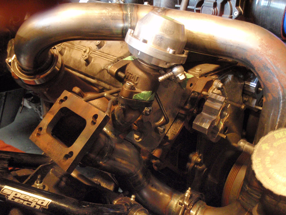
ROUGH mocking up cold side, just wanted to see overall what it'll look like. Need to finallize bends and order up some black silicon reducing sleeves and 90's...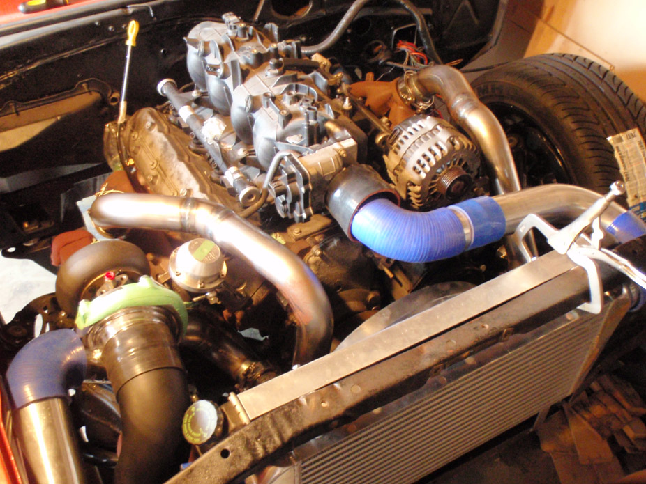
Got some cheap Recaro knock-off seats locally. Seem to be decent enough quality and fit me really well, and the bolsters are actually solid and non-flexy, but with some cushion. Most importantly, they were half the price of the cheapest "real" buckets I could've gotten, even before shipping, which would've been Corbeau's.
And they are black with red stitching to match my steering wheel and gauges.. haha. Anyways, a little mockup just to tease myself with what the interior will look like...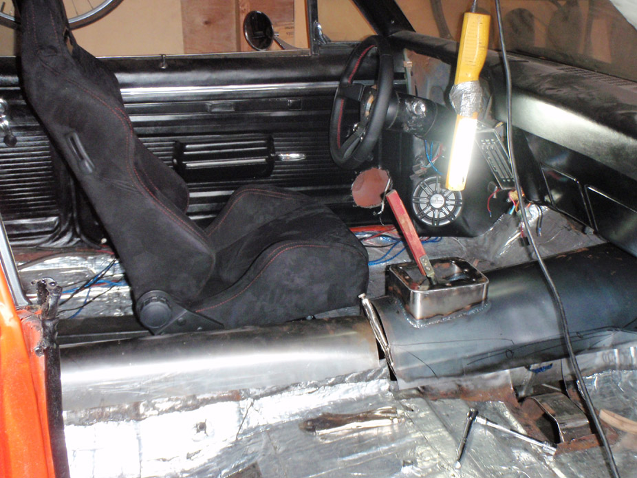
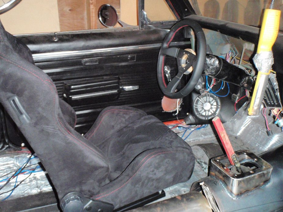
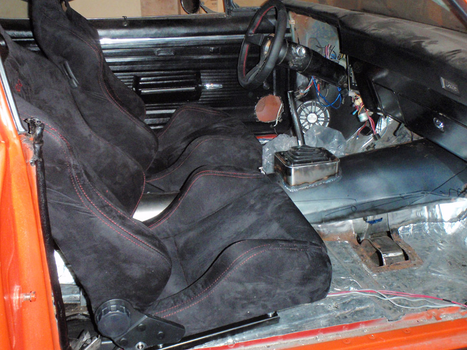
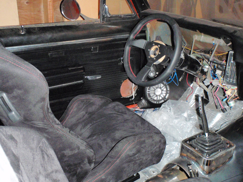
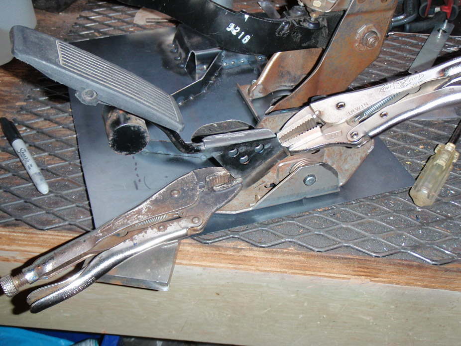
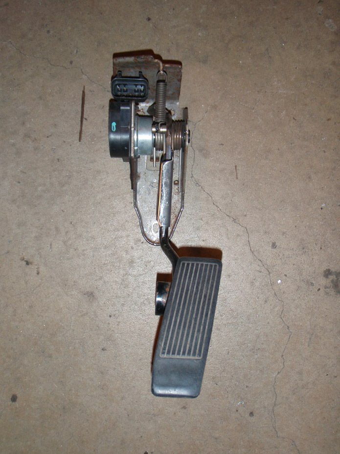
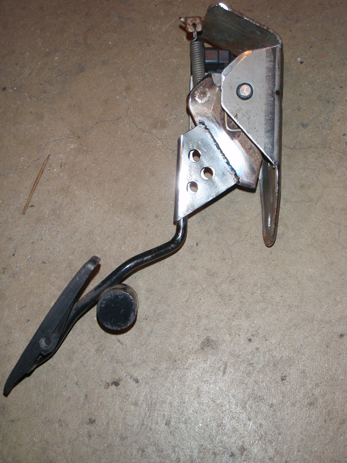
I traded a guy my old modified DBW pedal with the kick-down cable attachment because he really wanted it, and so it was time to modify another one (his one in the trade), I think I did a bit of a classier job the 2nd time 'round...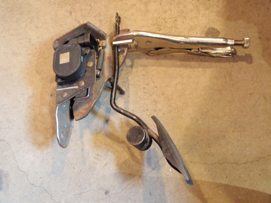
I have no idea what truck pedal he used, but the only "cut" part on it I could find (aka where the stock pedal would have been previously) extended up from the top... I have no idea how that'd work. But I compared it a shitload to pics of my old pedal and other than the pedal arm seeming upsidedown, it seemed identical...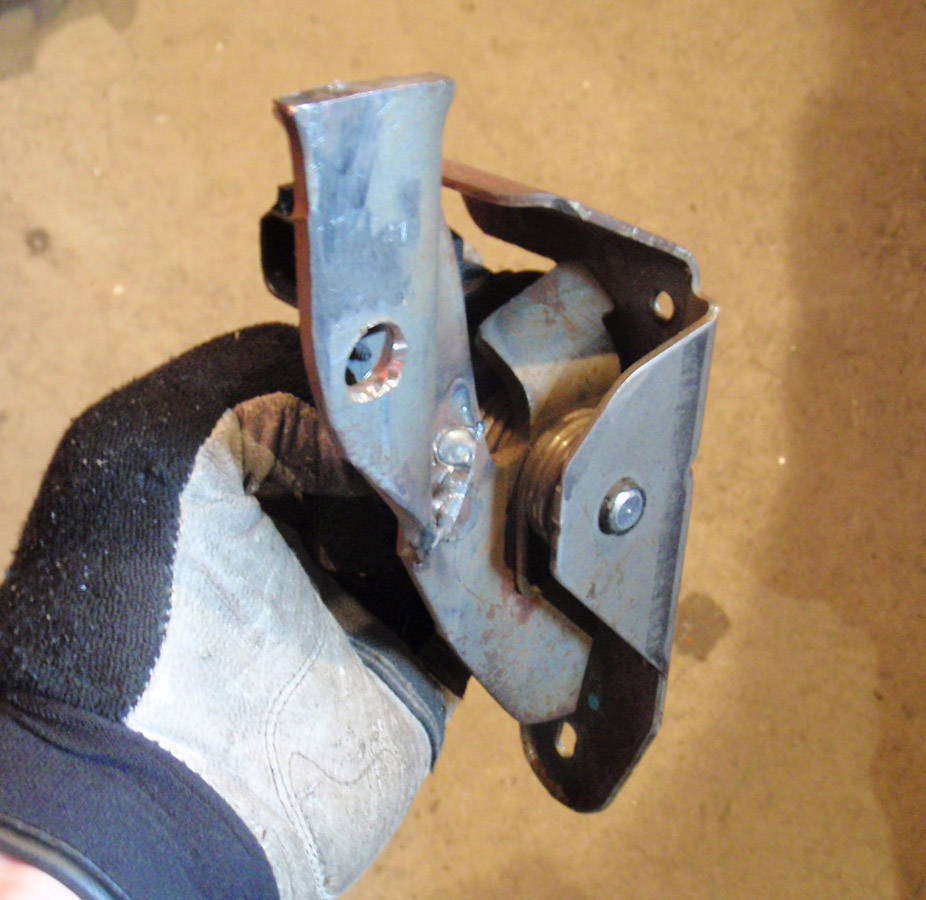
Mocked it up on the bench and climbed up there to test the pedal arm length AKA the pedal throw/travel, from zero to WOT, felt good...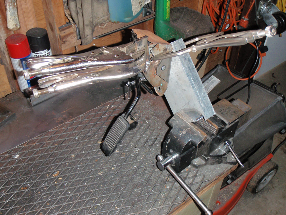
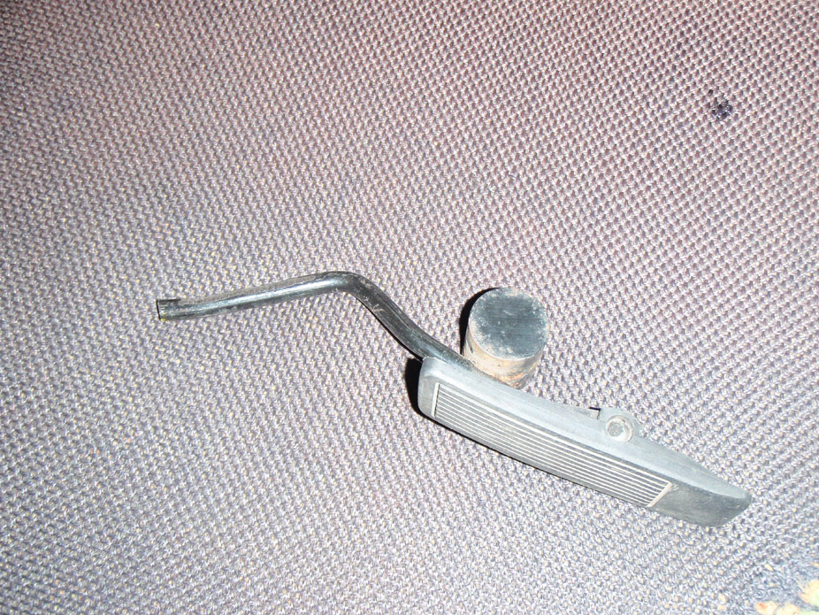
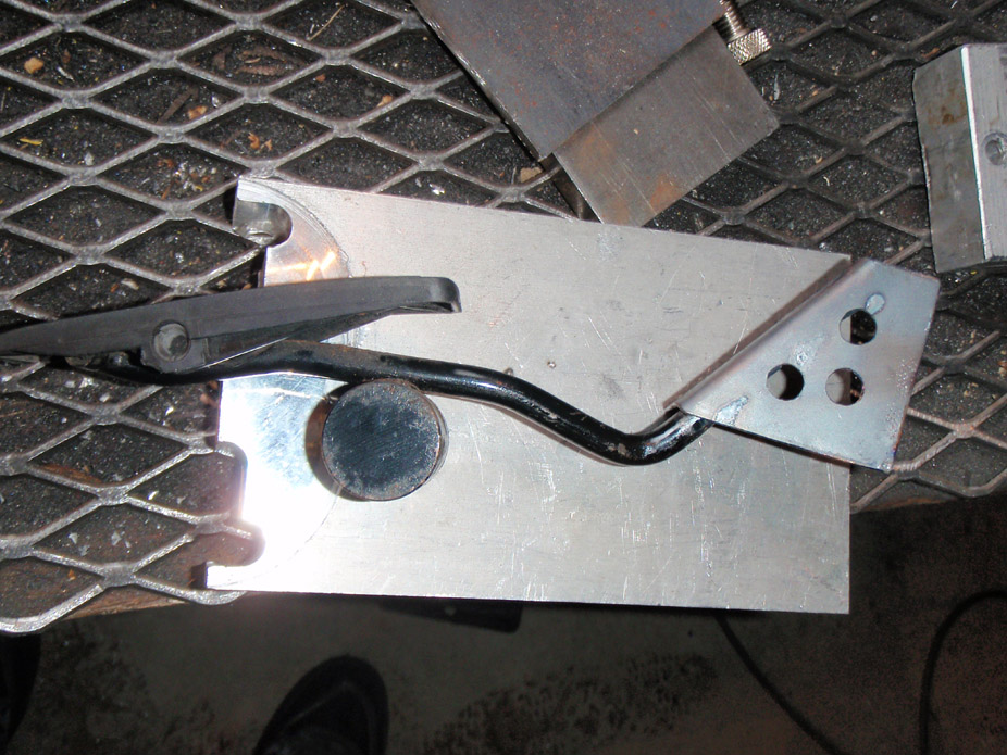
As I mentioned previously, I didn't have a clutch pedal lying around, and happened to have 240sx cluthc/brake pedals lying around, plus I like the 2-way assisting cammed spring thingy on the clutch pedal, so decided to use it.
First as always, break out the cardboard to template it up...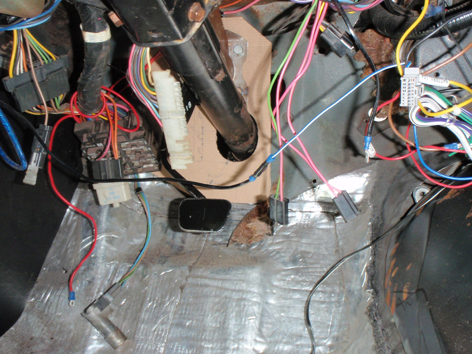
From various 240sx/s13/LS1 swap threads, it seems for the stock 240sx clutch pedal, a 3/4" bore master cylinder works best. I had originally wanted to use a stock 240sx master cylinder too for ease of fitment, but it is a 5/8".
So I decided to modify the Ram '98-'02 Camaro master cylinder I had, this included chopping off the threaded rod & clevis from an old 240sx master cylinder I had lying around, and welding it onto the Ram MC at the appropriate length, to keep the same MC rod geometry as a stock 240sx MC, which the 240sx clutch pedal is designed for...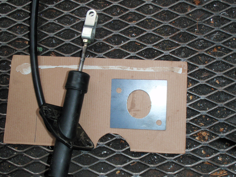
Once the proper 240sx rod length was replicated on the Ram MC, I then made a bracket to position it properly relative to the clutch pedal...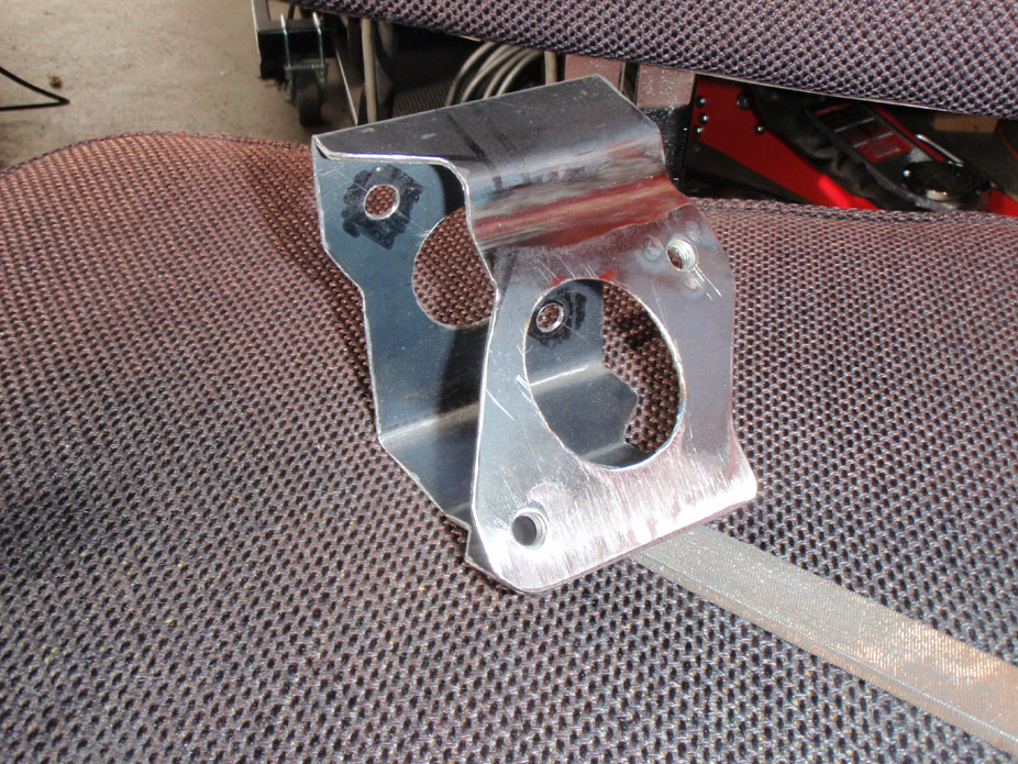
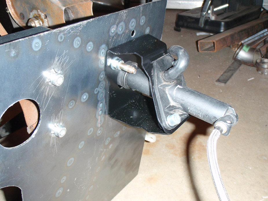
And the resulting overall "pedal plate" that just needs to be trimmed, then "cut & paste" into the Nova firewall...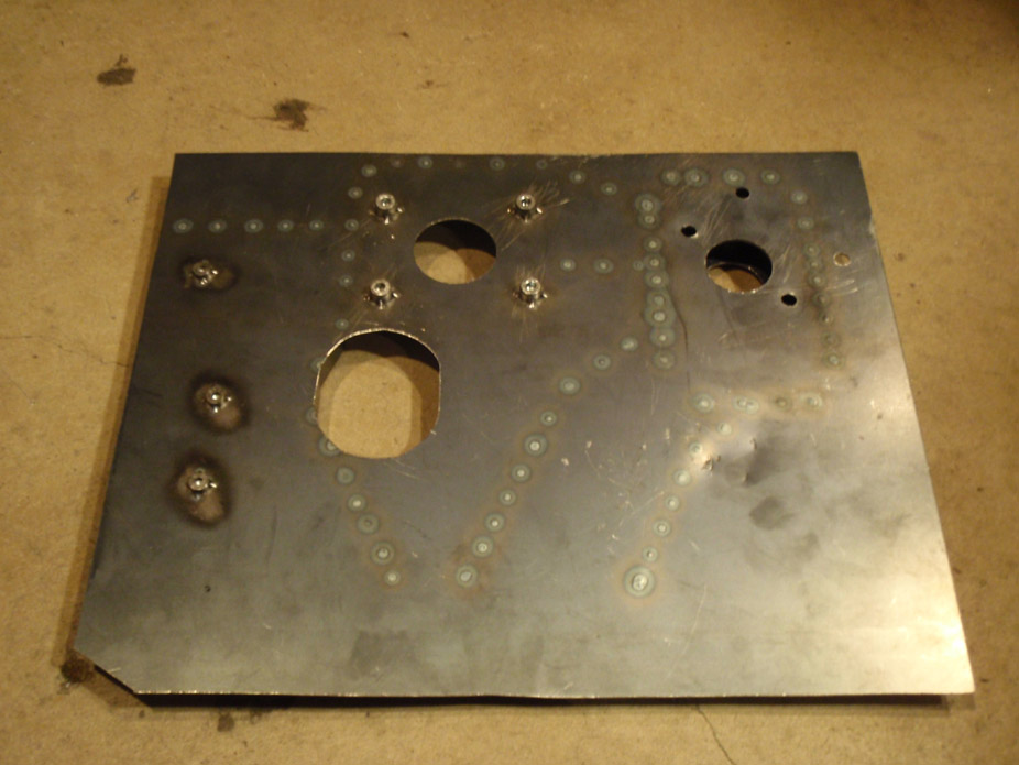
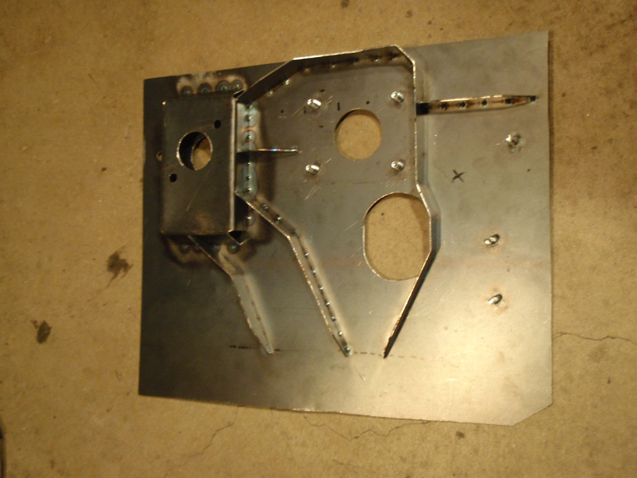
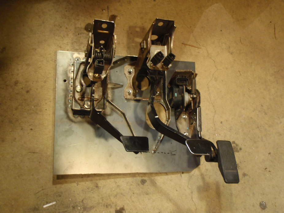
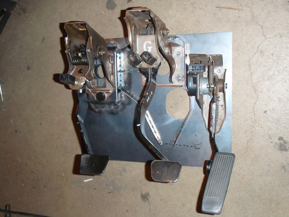
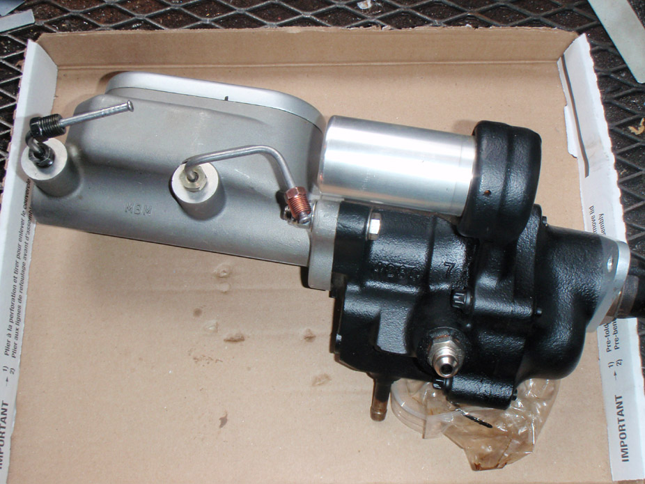
And finally, there's NO way that the hydroboost unit and the brake MC are gonna clear the driver side manifold with it flipped upside down, so, gonna go with I think a 7/8" or 1" manual setup, and this whole unit is for sale... anybody interested??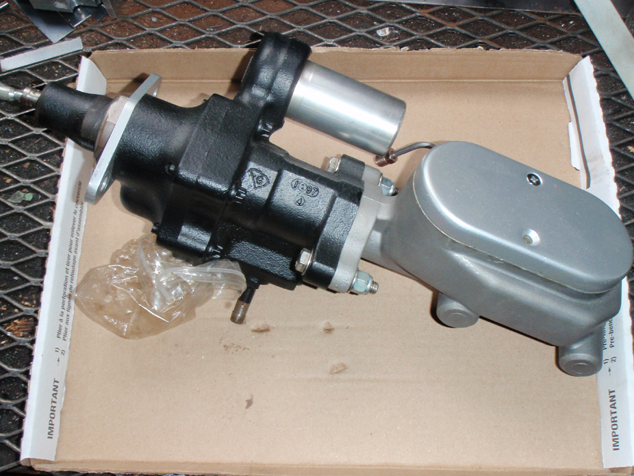
5-2-2011
So I'm moved back to Vancouver for good... finally some serious, consistent work can be done on this damn car.
Continued turbo plumbing mockup to see what I need to order.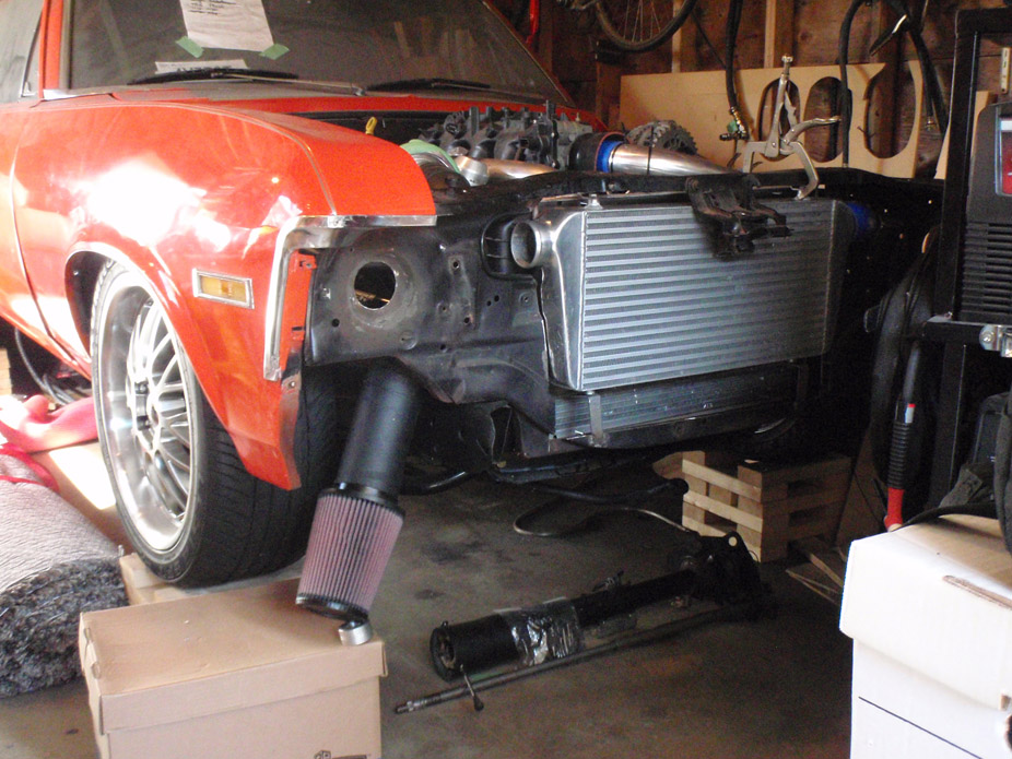
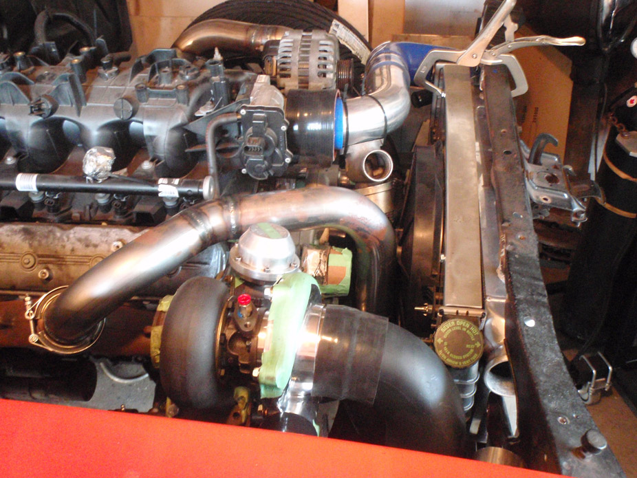
Going to have to notch the inner sheetmetal on the passenger fender so I can rotate/clock the compressor housing a little bit more up, to clear the stock inner fenderwell....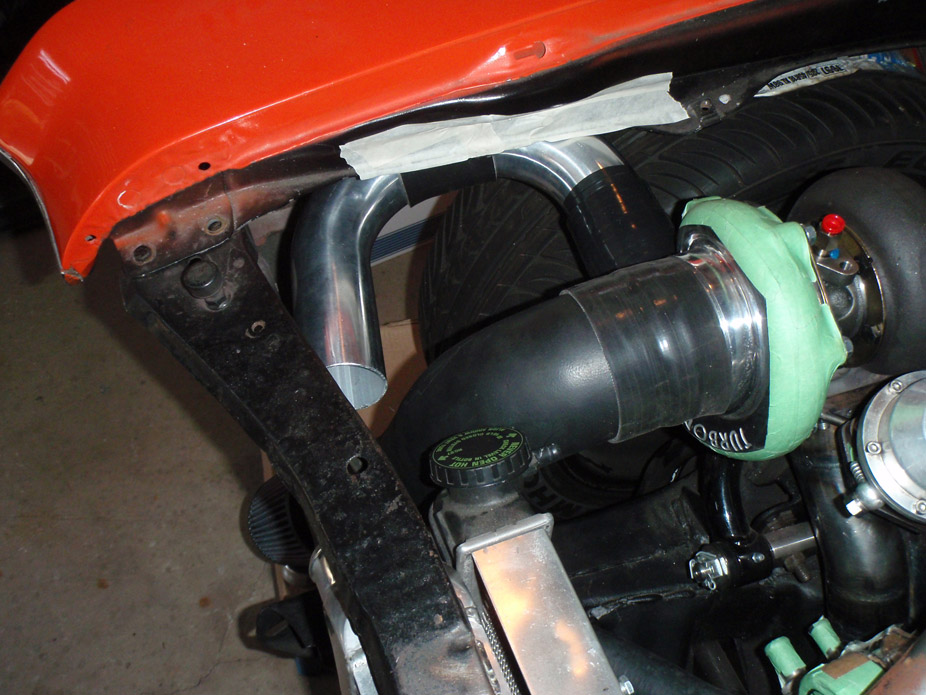
Potential BOV location. Other orientations would work but this is the only one that would allow a recirculation tube back to the intake, if I so chose to make one (still on the fence)...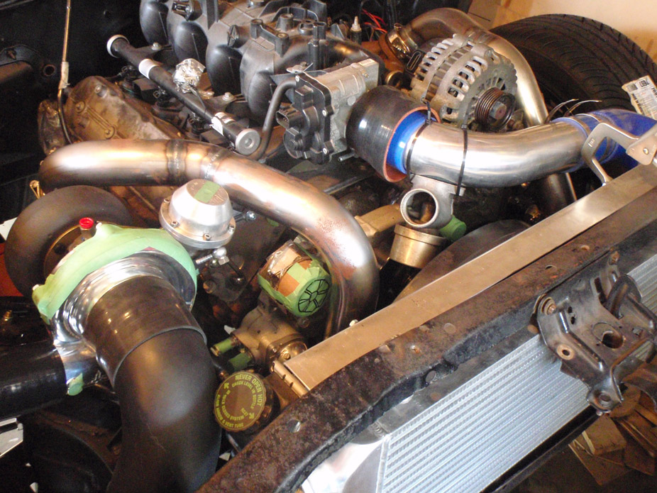
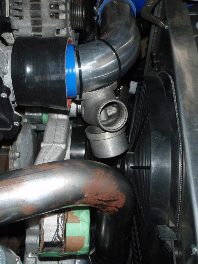
Nice direct pump outlet to rad, with a trimmer stock S10 45* lower rad hose to connect...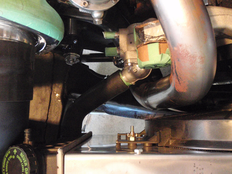
Good amount of clearance for upper rad hose too...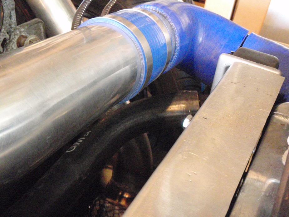
Possible recirculation pipe layout for BOV...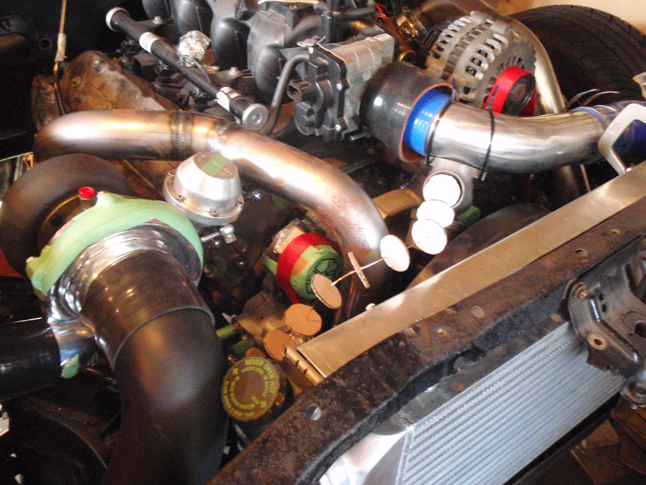
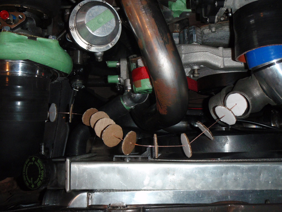
Now I need some input from you guys, I was getting worried because I really left consideration for the serpentine belt out of it when I removed the stock LQ4 idler pulley and put the passenger side hotpipe in its place, but feel relieved because looks like I have some good options.
I need some opinions on which layout is best. Most don't offer a huge amount of belt contact on the crank pulley... I don't like that. Most also place the belt fairly close to the waterpump return inlet.
Since I'm running no subframe bushings, I doubt my alternator will clear the stock hood now, so I will likely just make a new plate to mount the PS pump & alt to, keeping the pump in roughly the same place, but the alt could move down and/or outboard quite a bit and still clear the driver side hotpipe...
Option #1 (not good)...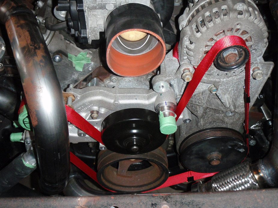
Option #2 (also not good)...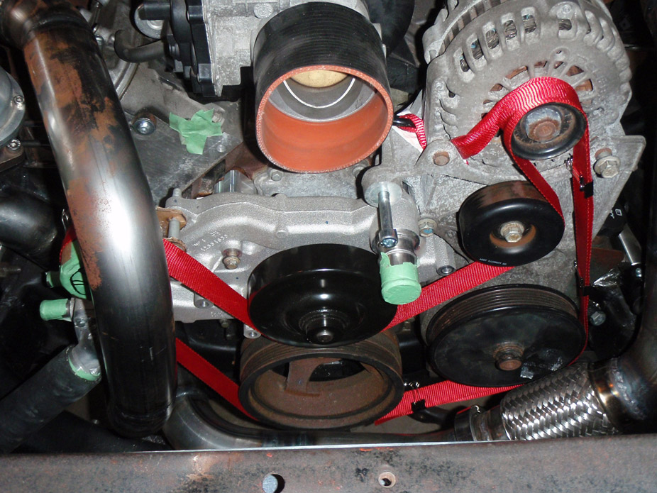
Option #3 (slightly better)...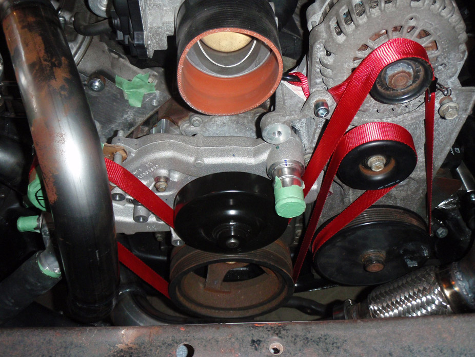
Option #4 (pretty good looking)...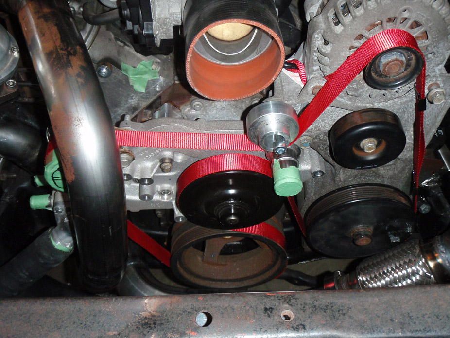
Option #5 (too crazy of a belt wrap?)...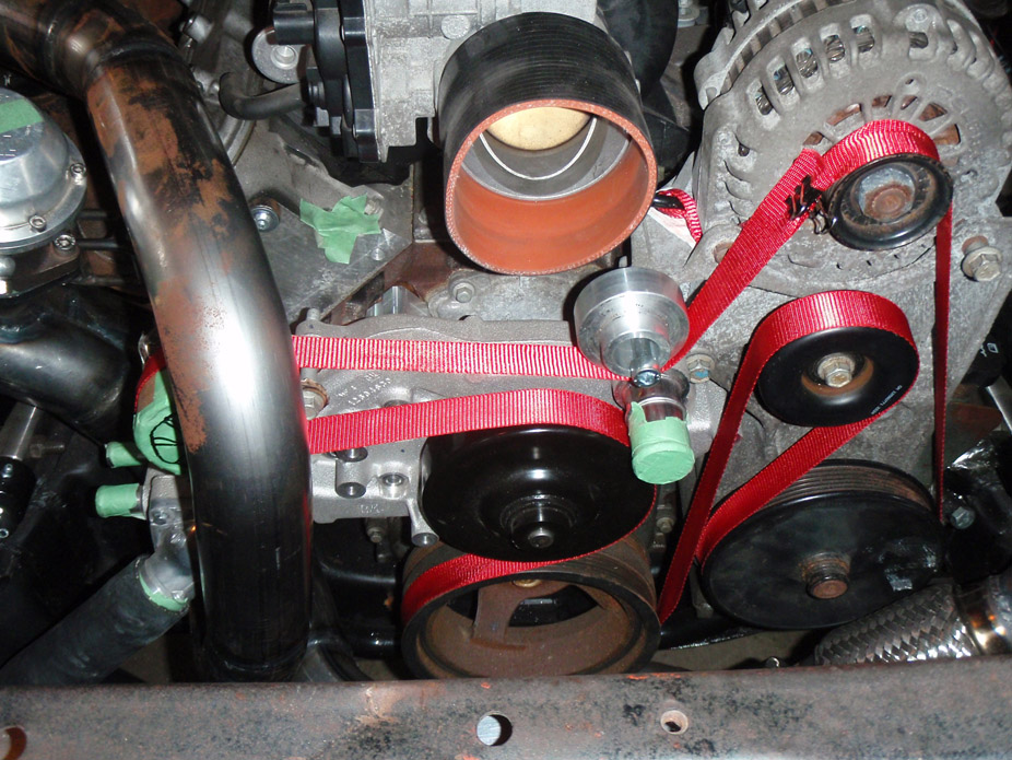
5-5-2011
Well I'll be a sonofabtich... the hood clears the stock truck accessories/alternator even with no subframe bushings!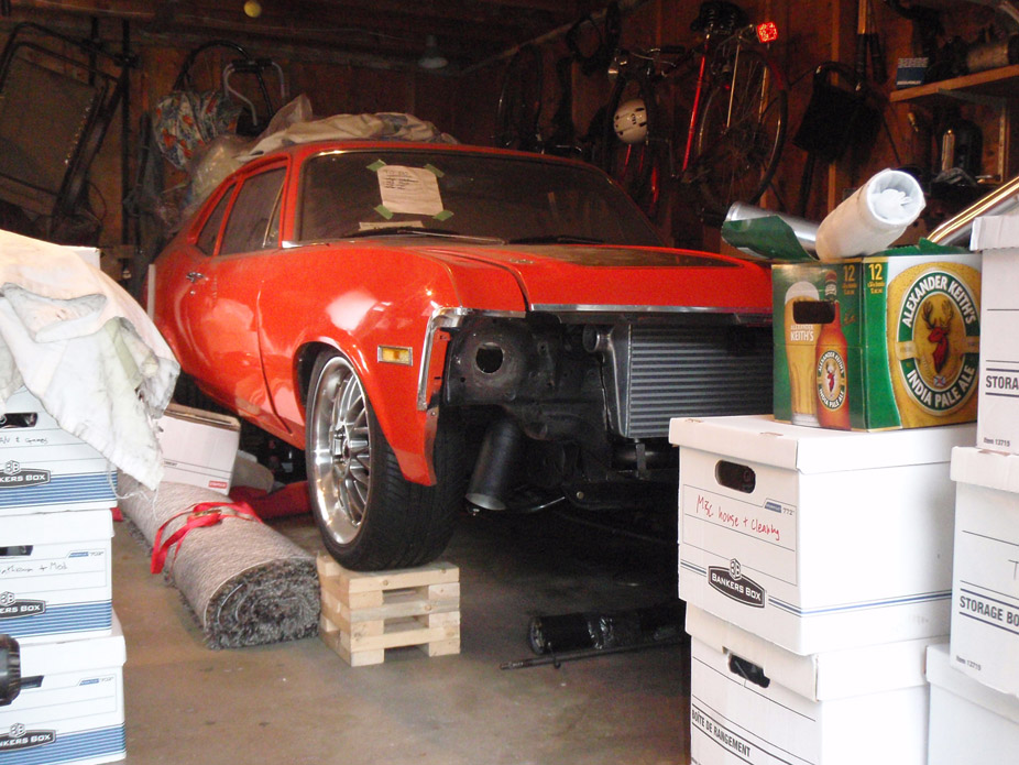
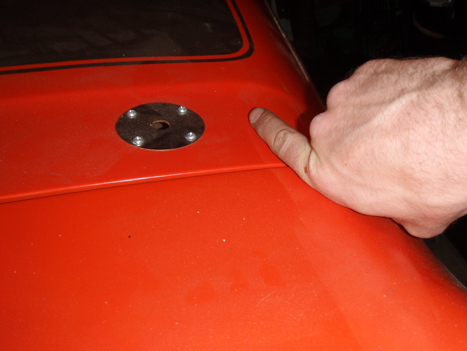
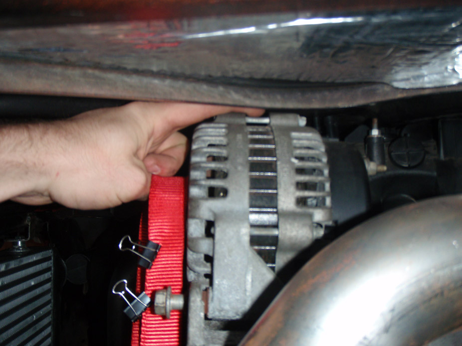
This sensor was the only thing getting in the way of the hood fully closing... anyone know what it's for??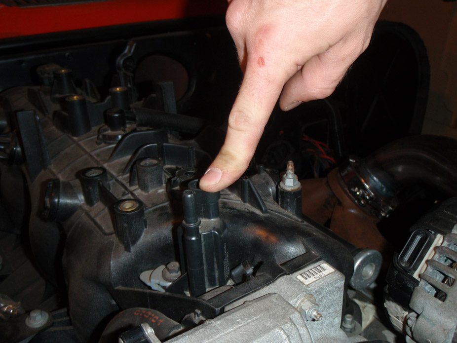
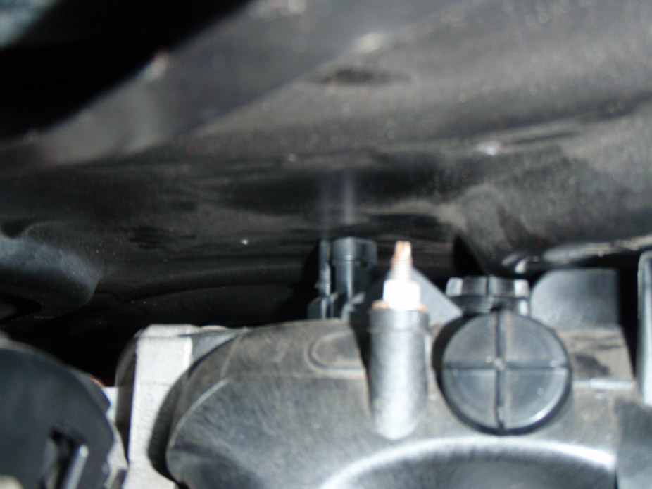
And a bunch of the plastic bs on the intake is all that comes close, will trim off and make it look a bit better...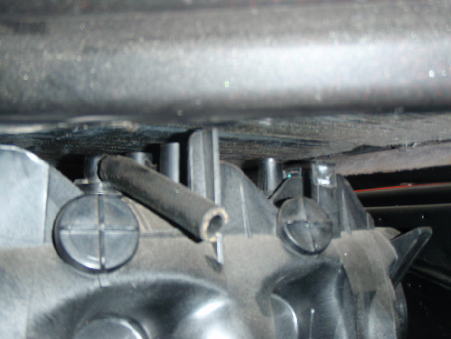
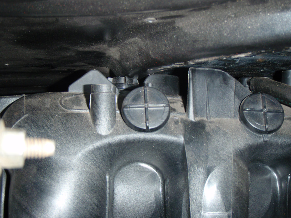
5-9-2011
The last step before I can take the engine out (hopefully) for the last time... made a driveshaft loop/subframe connector cross-brace...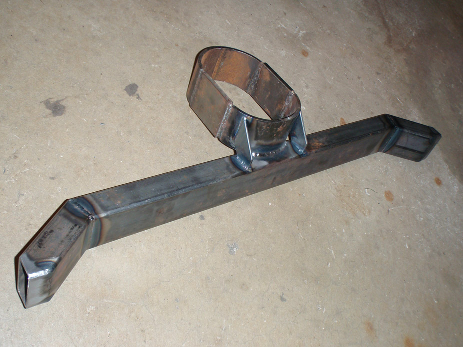
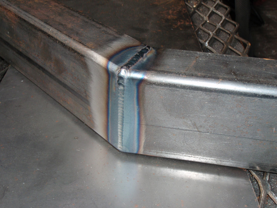
Welds are improving a bit
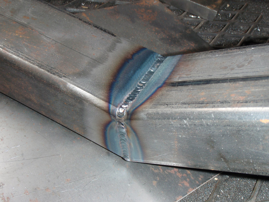
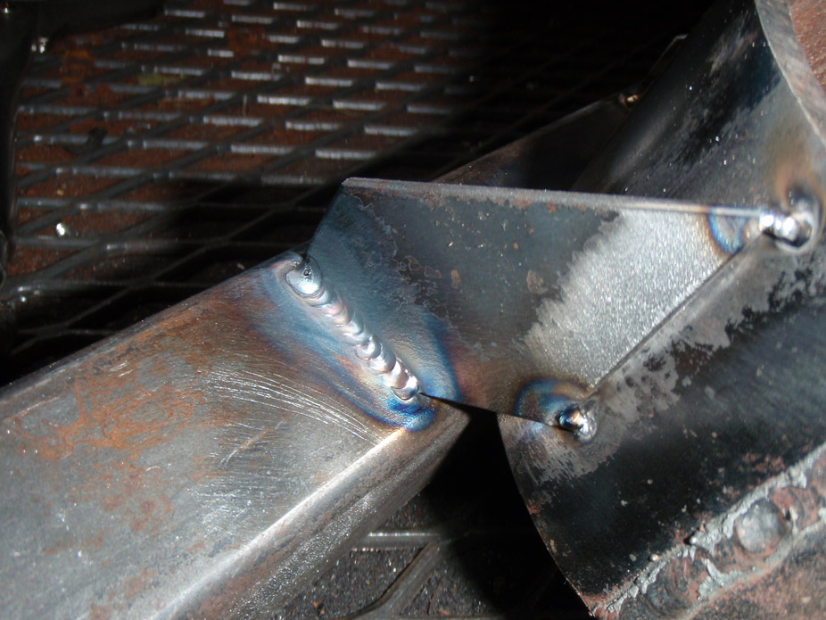
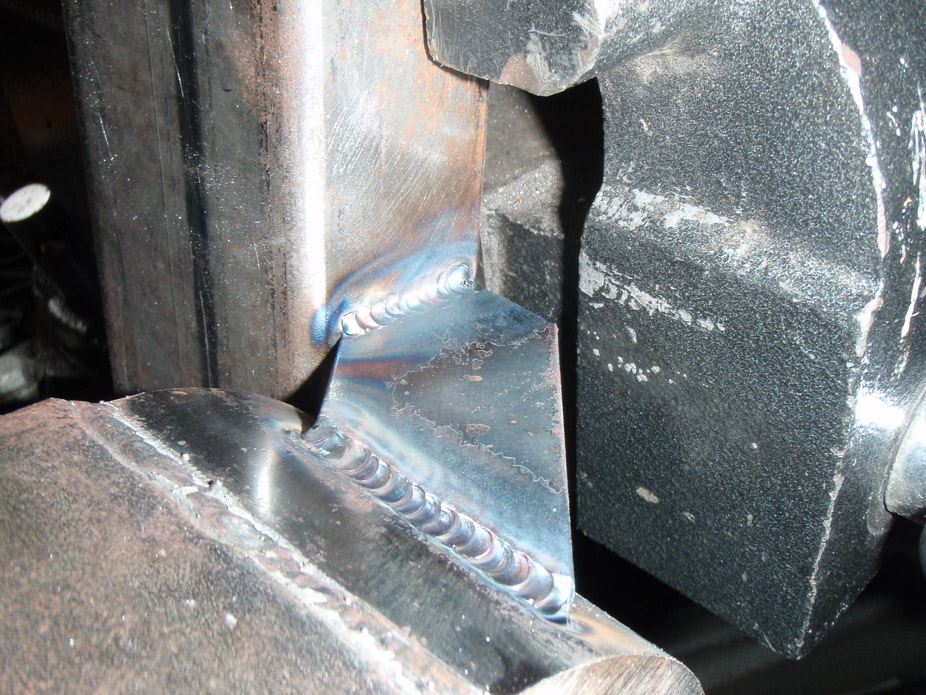
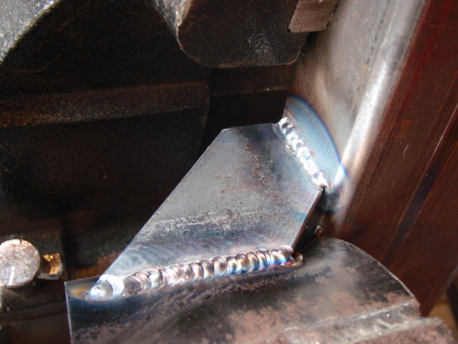
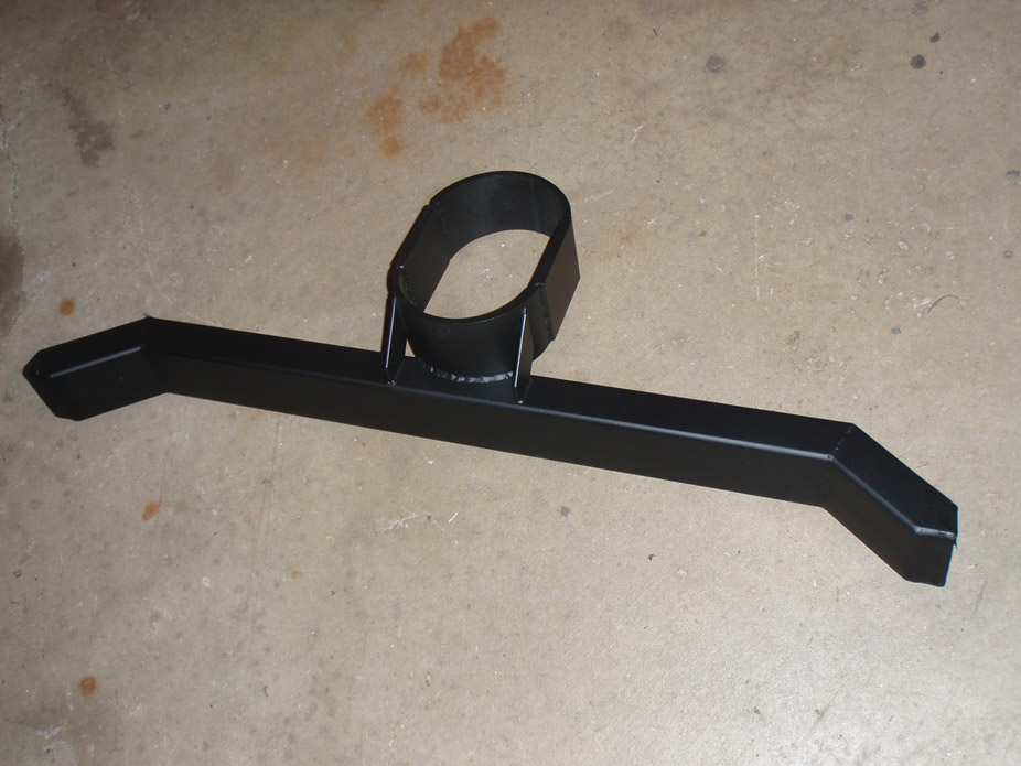
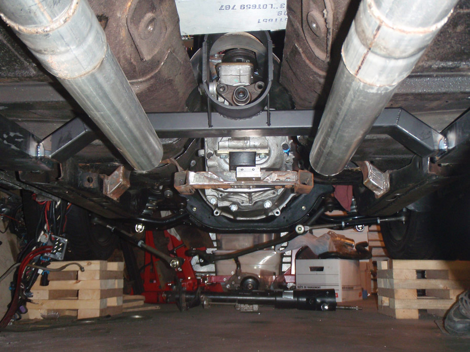
Started making the downpipe, got it to the point where I could finish the the wastegate dump pipe with the engine out of the car, just wanted to get it far enough to make sure it'd fit the inner fenderwell no problem.
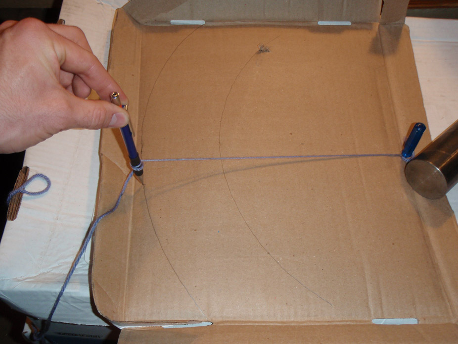
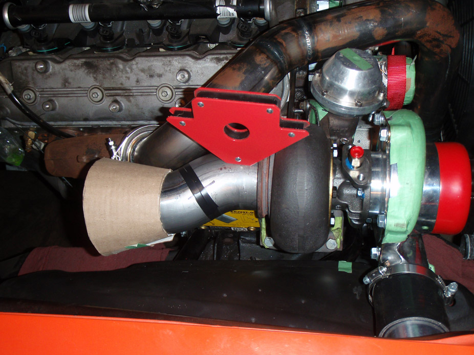
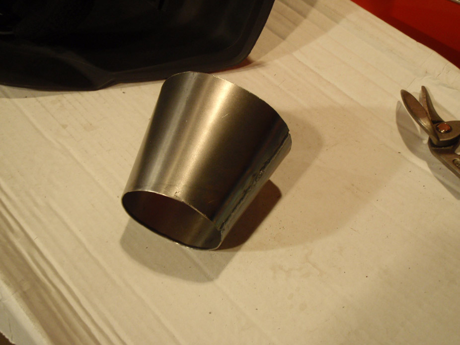
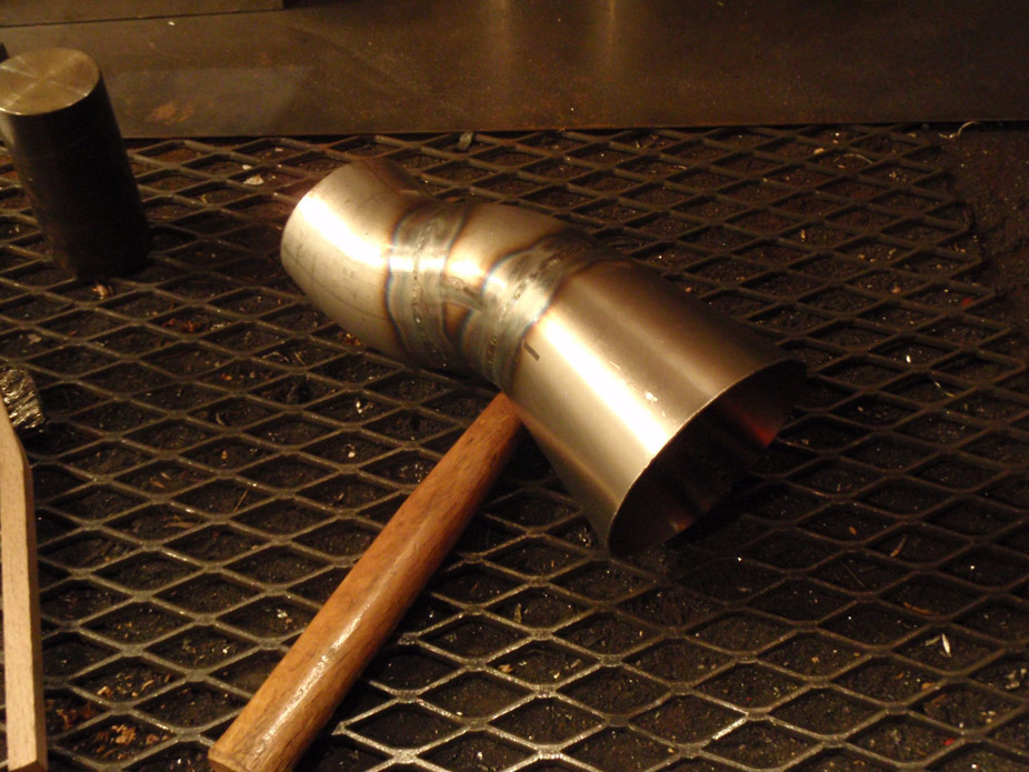
Idea is to go from the TC76's 3" outlet to a 4" to eliminate backpressure. Wastegate dump pipe will merge with downpipe right at the cone section.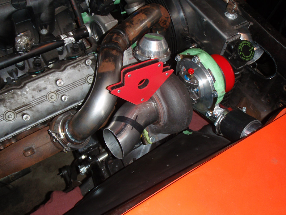
Like hell I'm paying $25-30 for a cone, just needs a bit of garage engineering...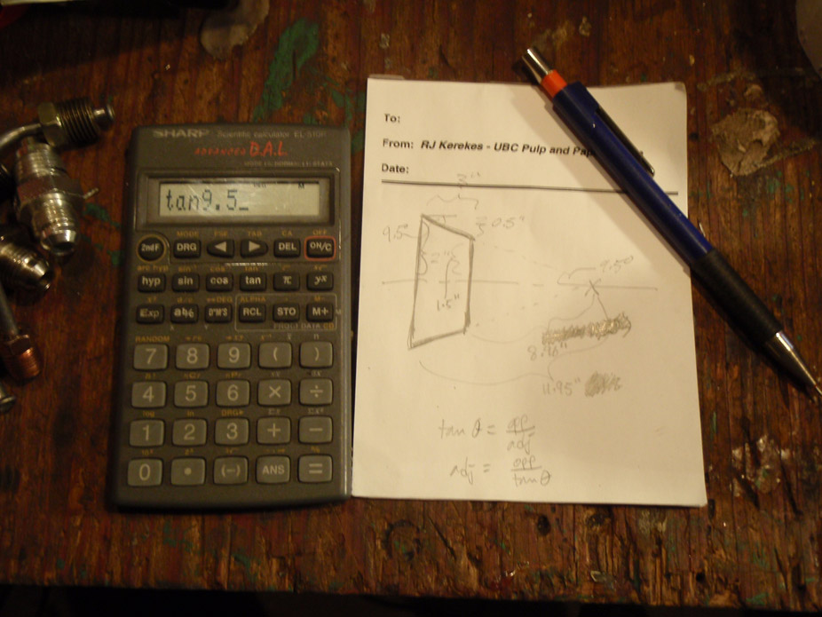
5-11-2011
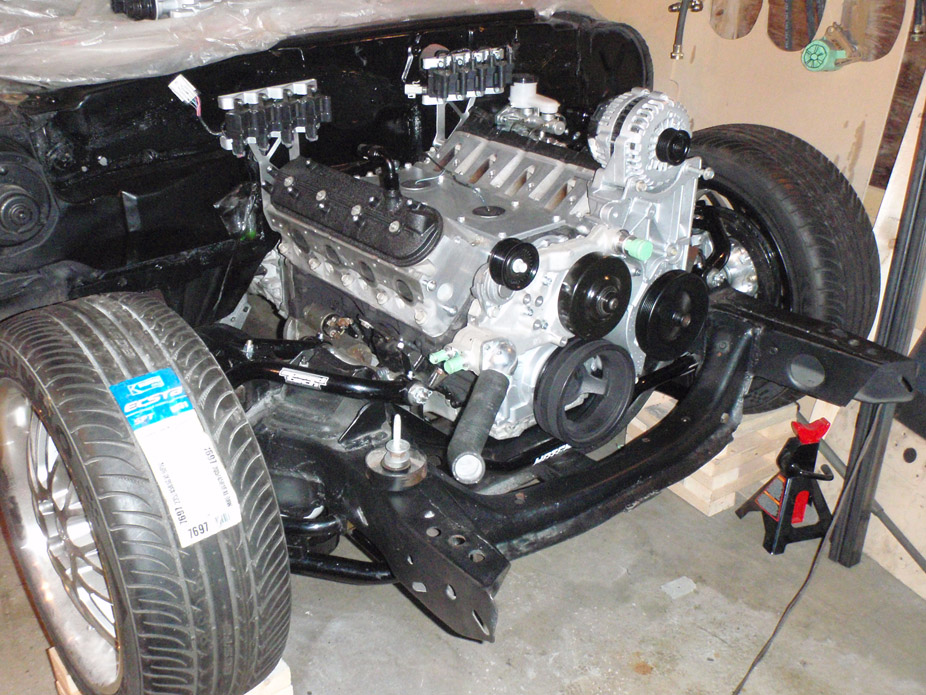
Pulled the engine last night for hopefully the last time in a while...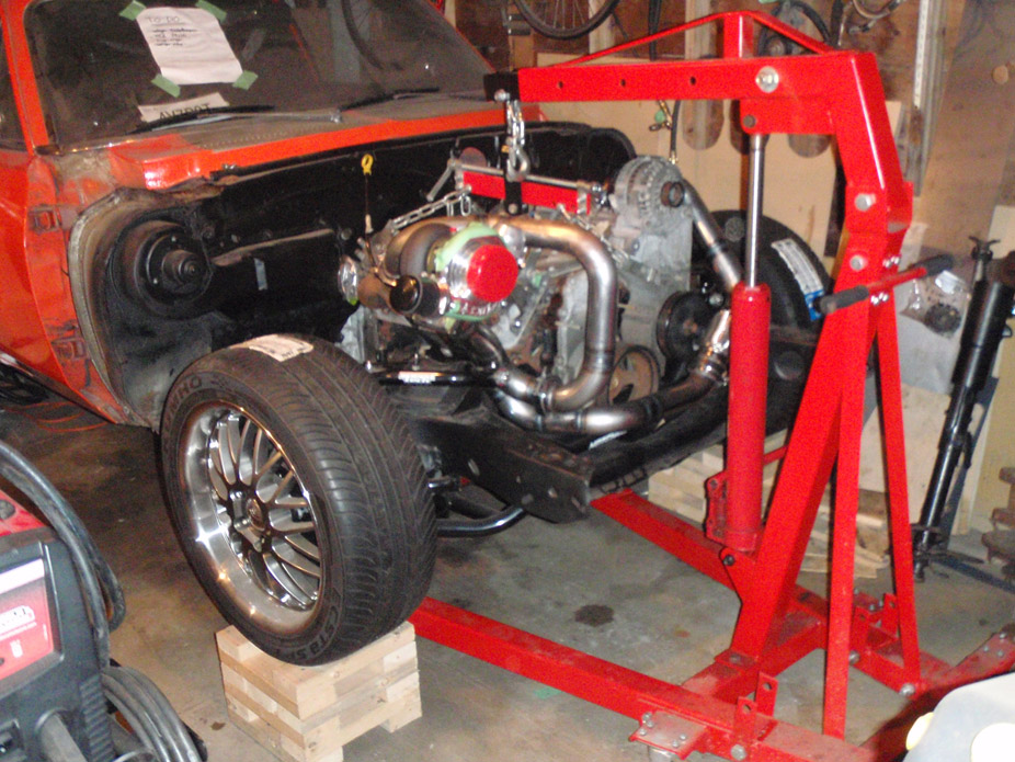
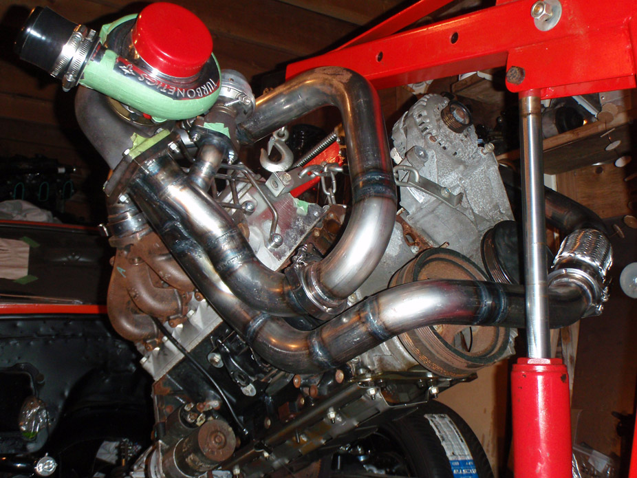
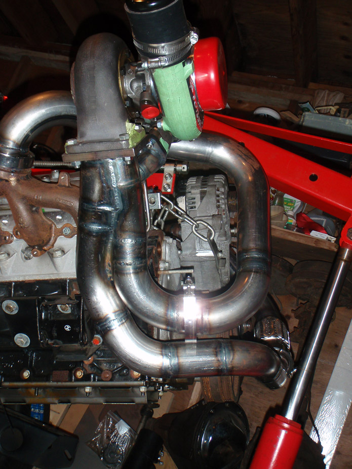
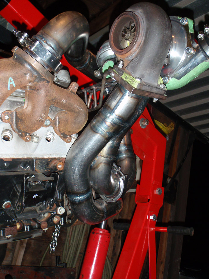
Made a grommet/plate thingy for the wiring harness to pass through the firewall... will cover up & seal a 2" hole...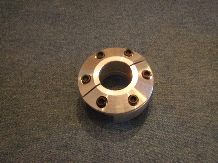
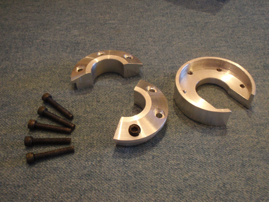
5-13-2011
Nothing exciting in this post, just though I'd share a tip, for how to lock up the flywheel/flexplate when trying to loosen/tighten those 6 crank bolts, check the black bolt...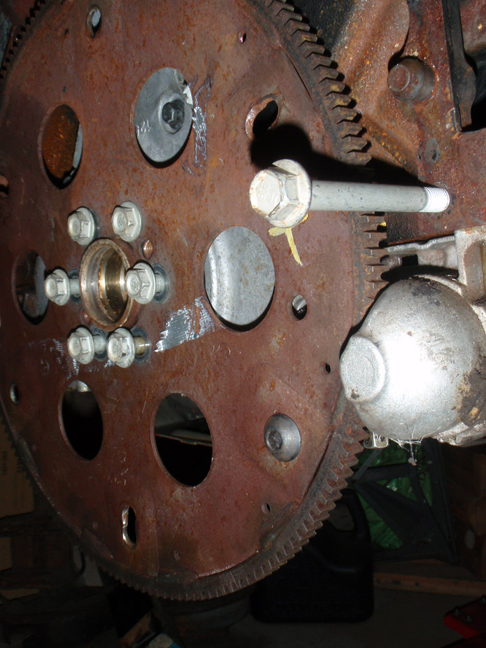
Tightened the 1st nut down hard then put the 2nd nut on there to protect the threads/block, then rotated flexplate till the bolt/nut hit it...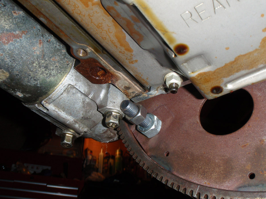
Lonely looking, this is gonna be a lonnnng weekend of wire wheelin' and cleaning so I can paint it.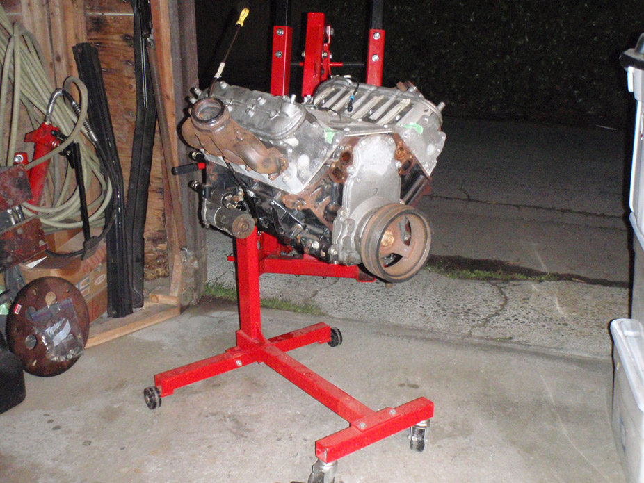
5-15-2011
Painted the block VHT engine paint flat black, wasn't expecting it to be that flat, but whatever it won't be too visible...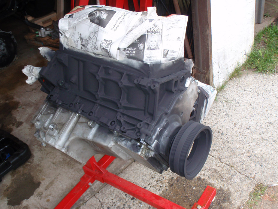
Figure it's best not to leave it to just those 6 bolts to hold onto the engine, so welded the stands in...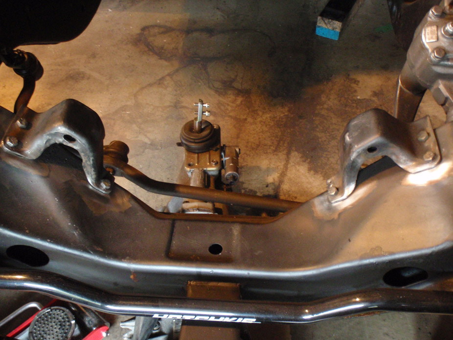
TIG welder is by far the best investment I've made so far, and the rolling cart is by far the most useful thing I've fabricated yet, it's so easy to make accessible...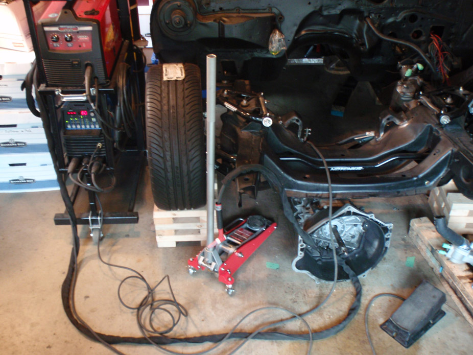
Not the cleanest welds but I had to change to at least 196 different straddle/crouch/hunch positions to get the angles...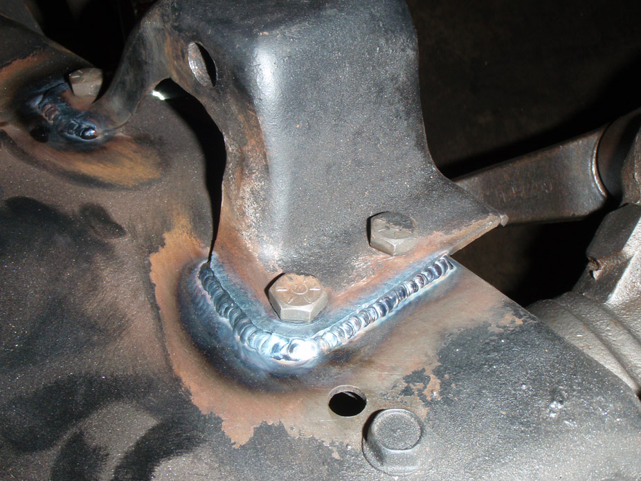
And then I started playing with aluminum...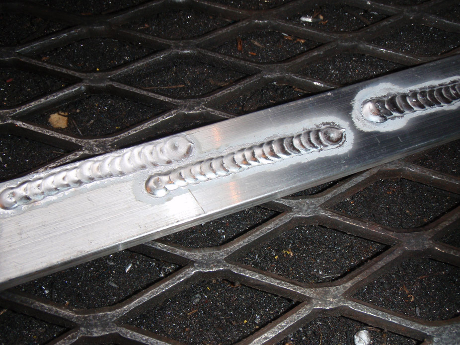
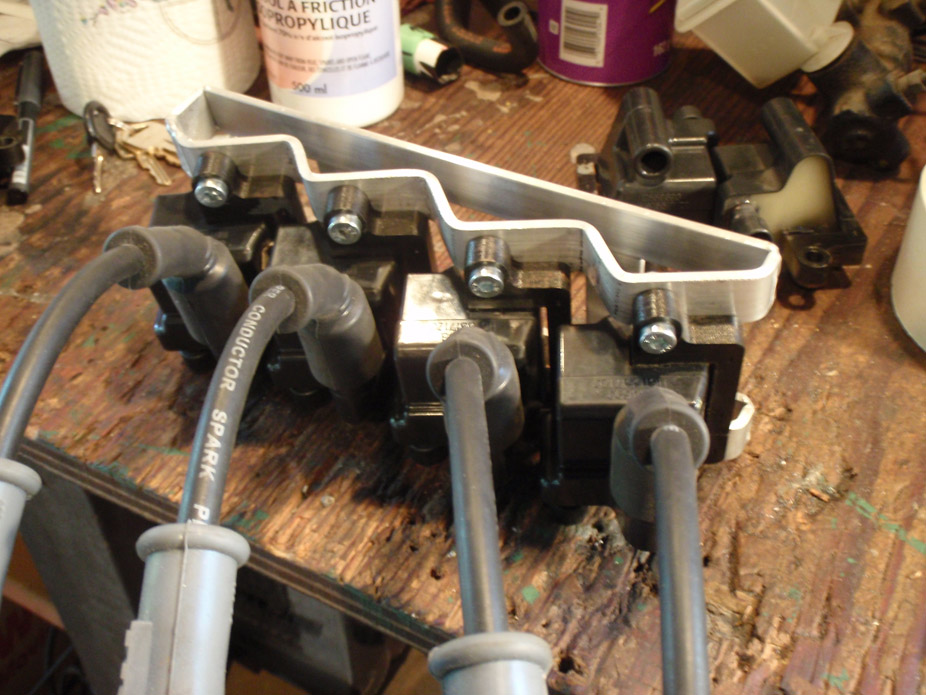
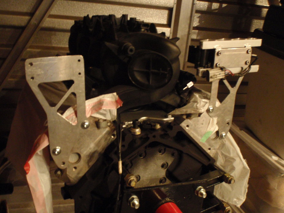
And started making a coil relocation bracket. Making (more like replicating) the bends was NOT fun but will be worth it, ran out of Al. plate today, but the first one turned out better that I was expecting.
Was originally going bolt to the side of the block below the manifolds but now I kinda want to show it (them) off either on the firewall or bolted to the back of the heads hovering over the aft end of the valvecovers...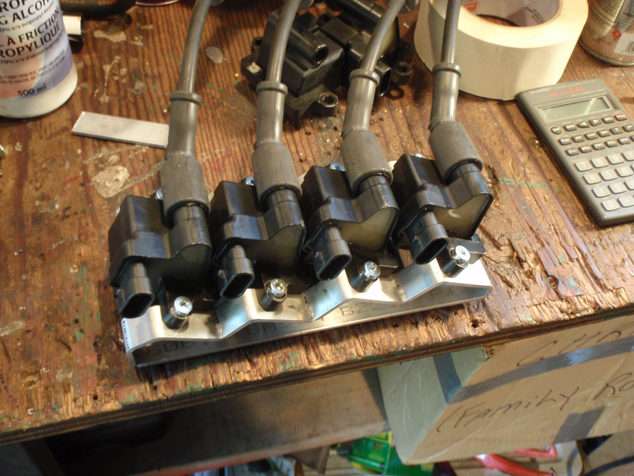
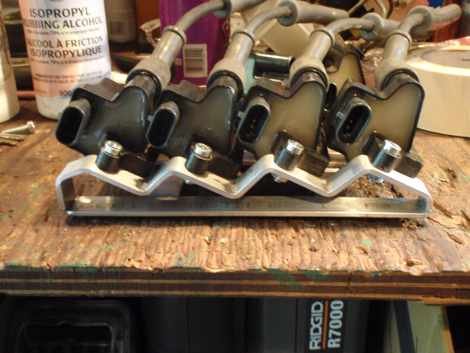
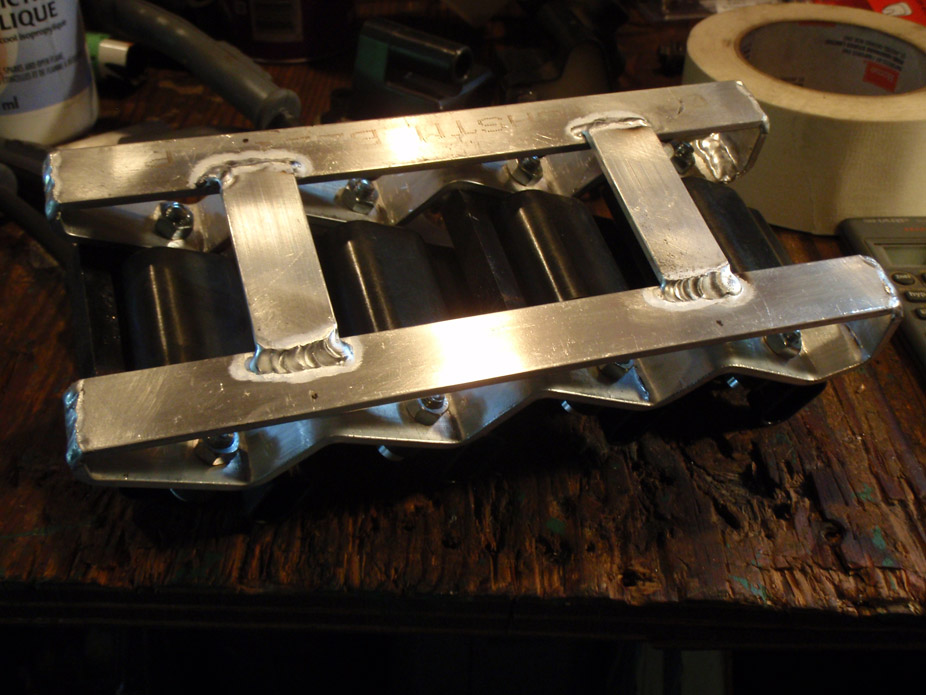
5-19-2011
Got a shipment in the mail, not sure if it should be exciting or depressing....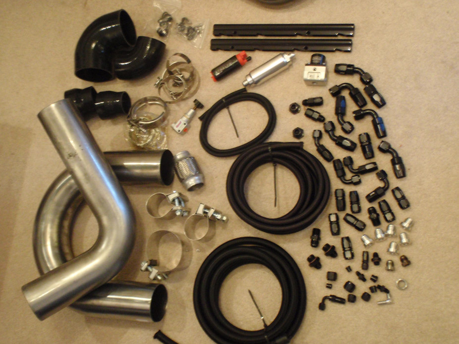
5-21-2011
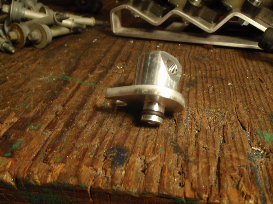
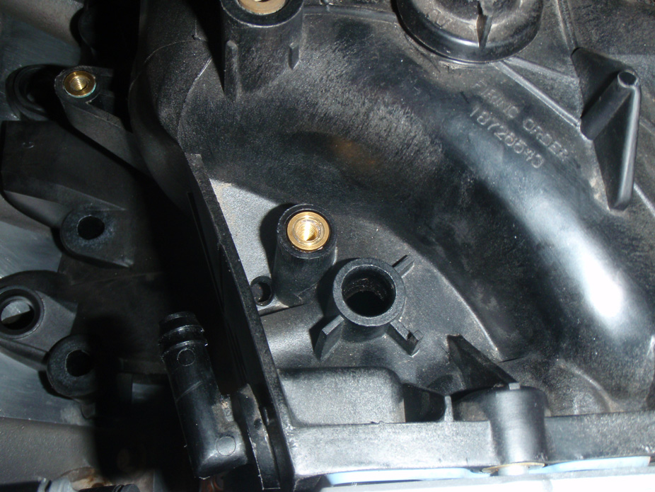
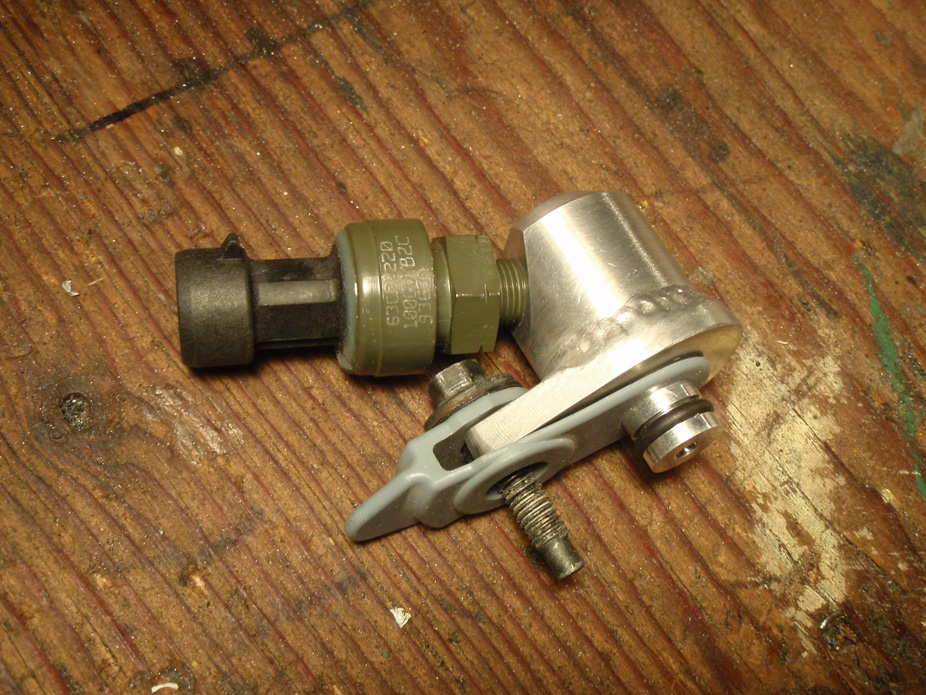
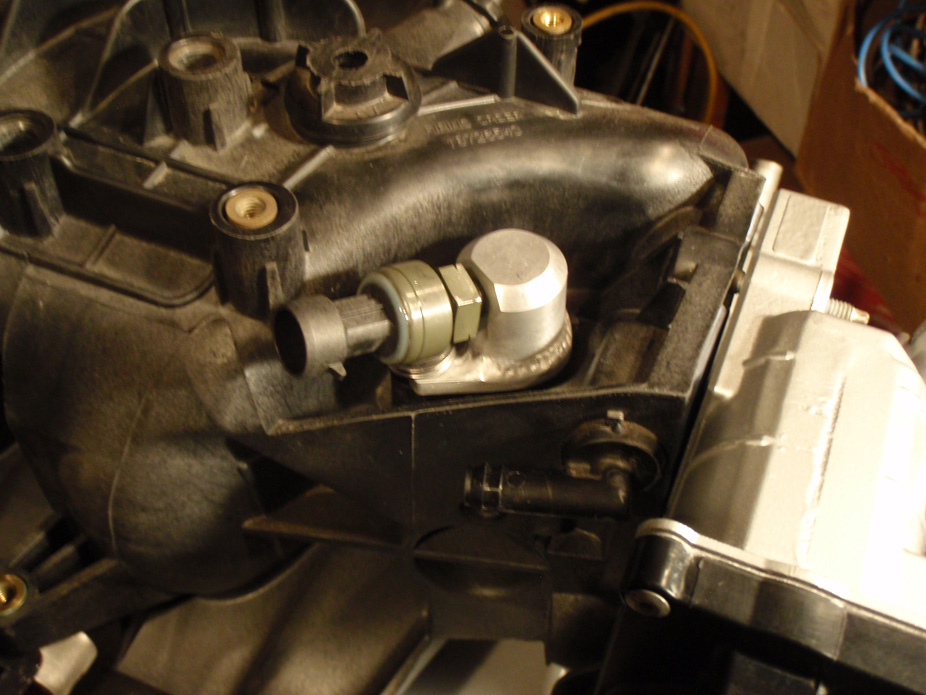
Made a fuel evap purge solenoid blockoff plate, then thought maybe I could thread it and have it for a boost sensor, but it ended up stacking the boost sensor as high as the solenoid it was supposed to be replacing (entire point was to get rid of that height because it hit the hood). So made an "addition" for the sensor to thread into...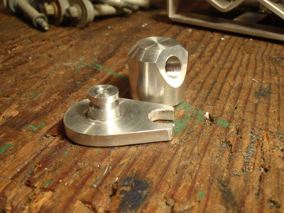
5-23-2011
Today was not a good day in the garage, one of those days where it seems like everything is going against you... broken lights, broken tools, screwing up measurements, burns, and tripping all over the place. Well at least it seemed to be getting better as I made good headway using the MIG for the first time in over a year to weld in most of the trans tunnel, then I ran out of 75/25 mig gas
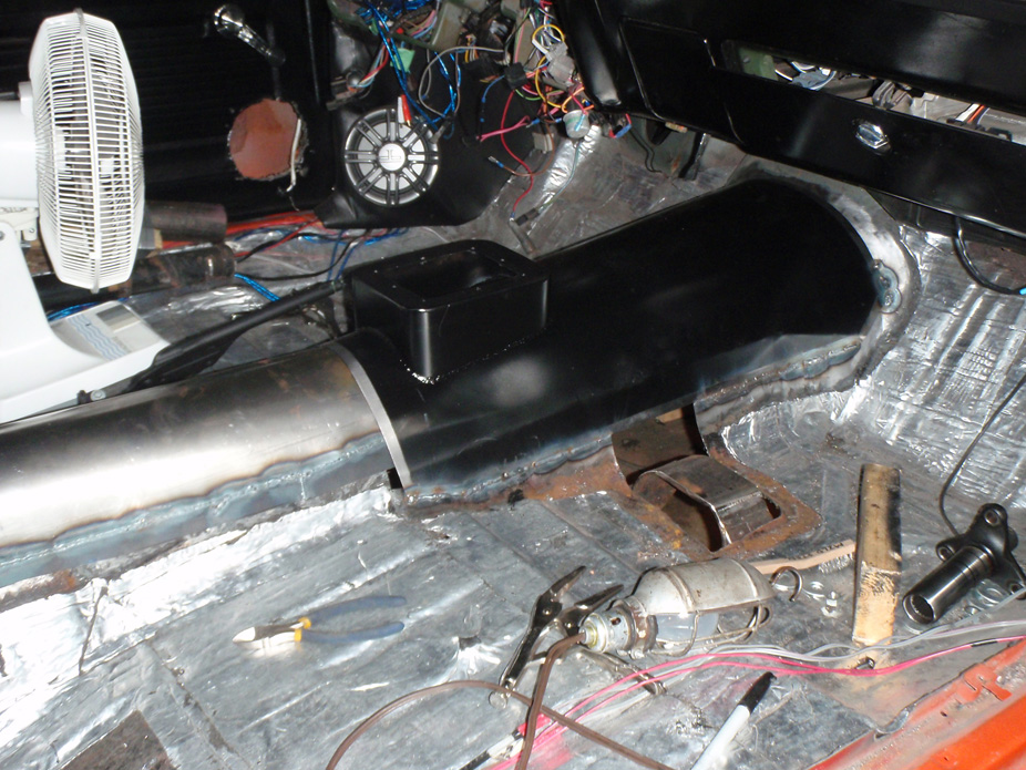
Moved on to the ebrake stuff since once I get more gas the driveshaft tunnel will be ready to go in.
Of course, this is another 240sx part, nice light piece that has simple mounting and even has a neat little bulkhead stop to go thru the driveshaft tunnel. Made a pedestal mount for it too...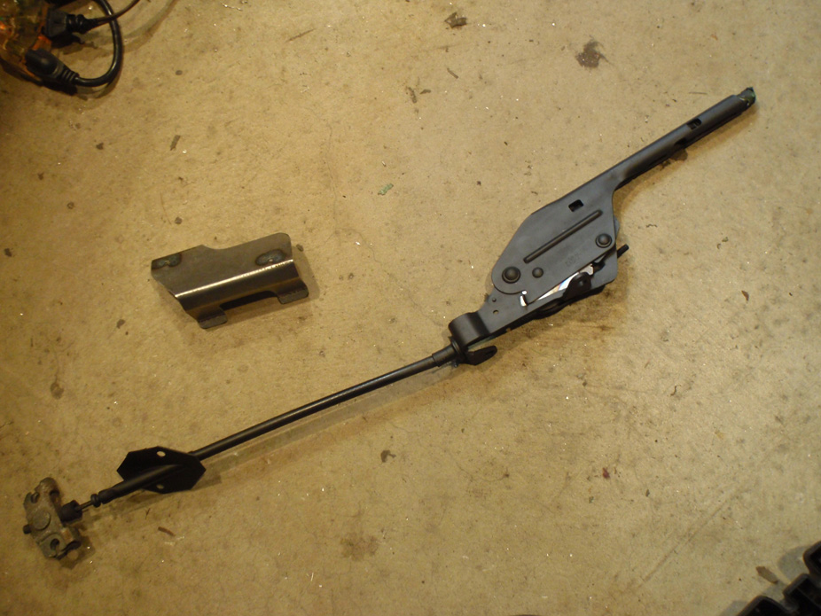
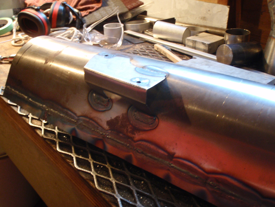
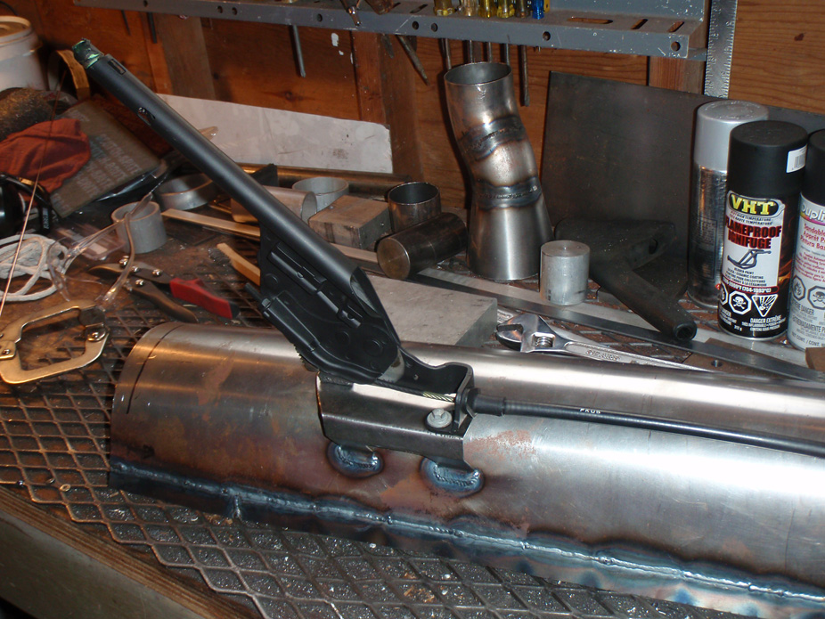
My garage is wired so that when I turn on the main lightswitch next to the door when I first walk in, all lights turn on, including a clock radio which resets itself to 12 everytime I start up in the garage. After a long day of mildly chipping away at all the little things left, the clockradio read this (been making too many of these happen lately)...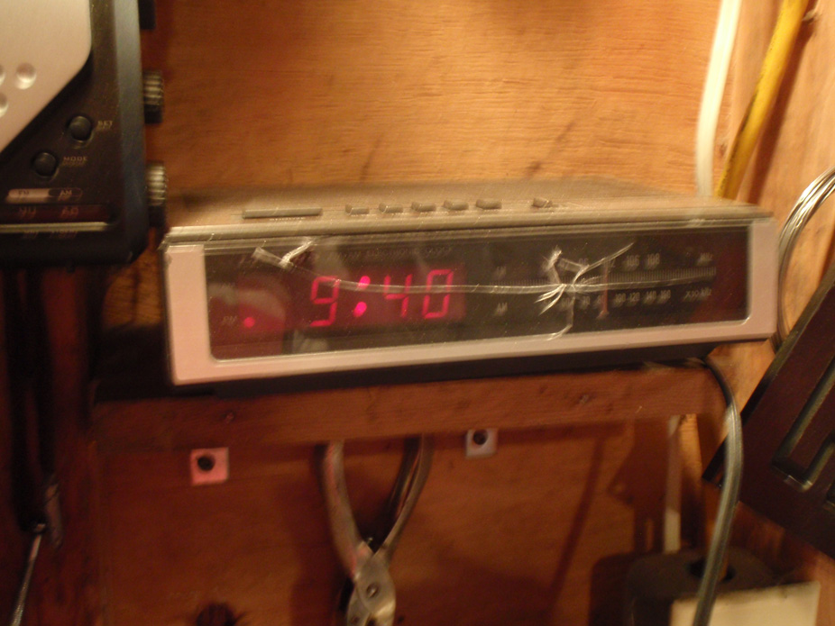
5-27-2011
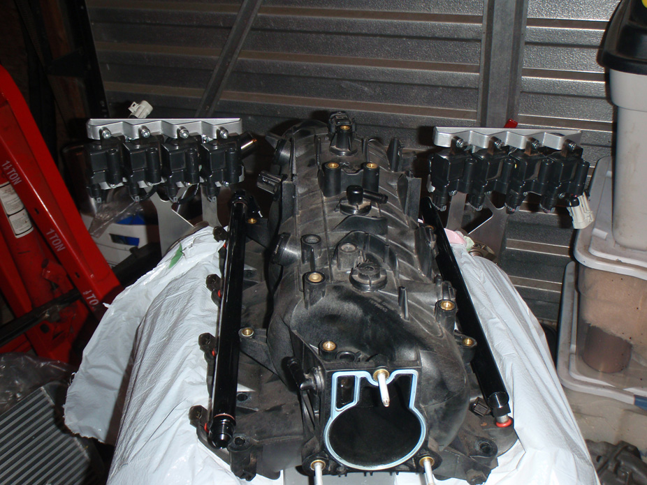
Finished up the coil relocation stuff today. Only took me a couple minutes to mill them out to make em look a little fancier, made out of 1/8" aluminum plate, a little flimsy so on the fence whether to remake them in 3/16" or 1/4", but they'll do the job for now. Bolt to the back sides of the heads.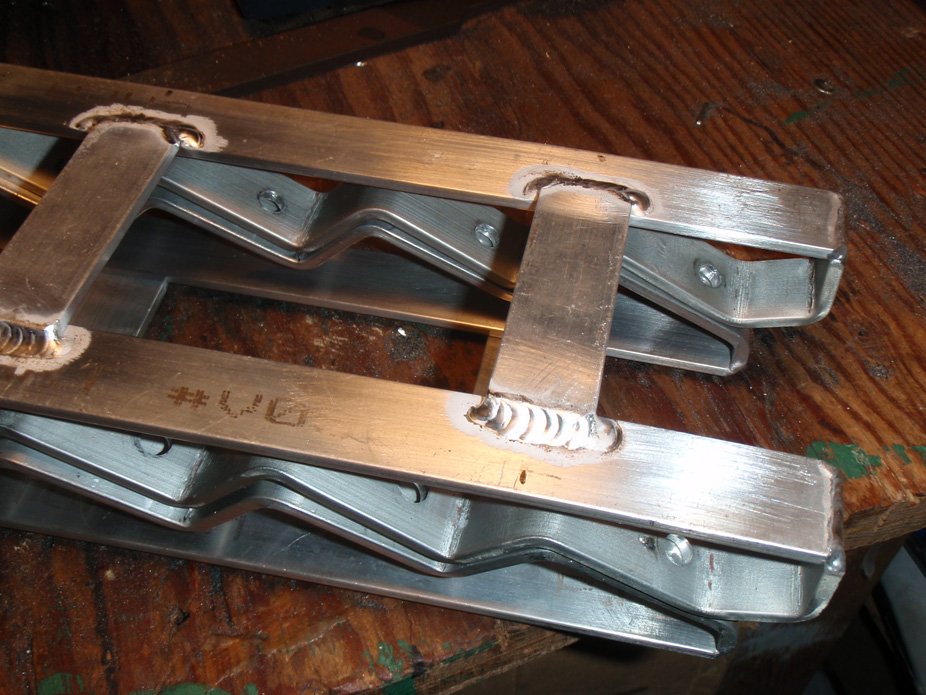
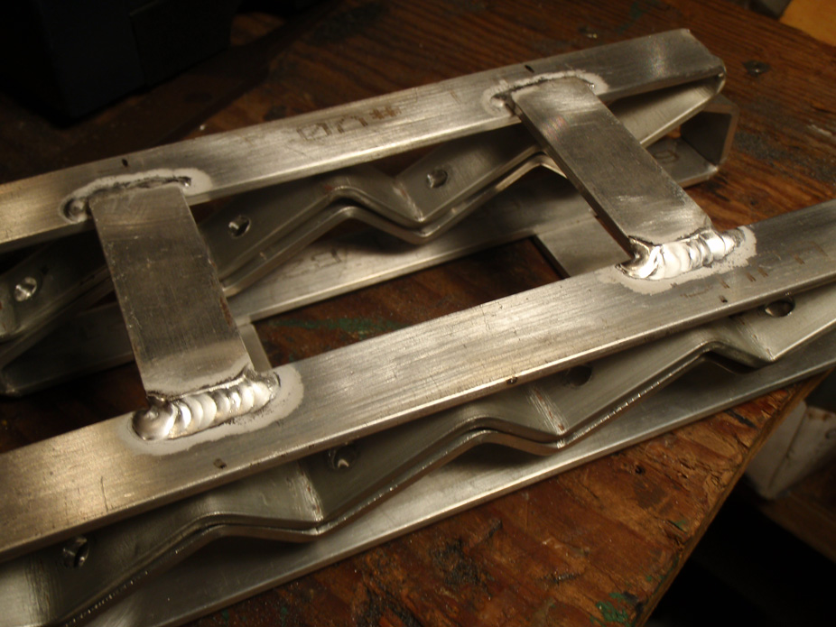
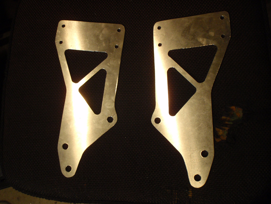
Modded the truck pan for the 2nd time. Originally done 3 years ago 100% by another guy for some beer, he didn't do the best job, and it still hung below the subframe cross-member about an inch, now it'll have good road clearance at 5.25" from the block to the bottom of the pan.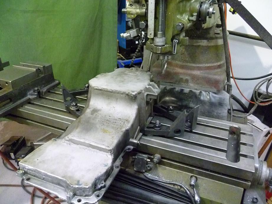
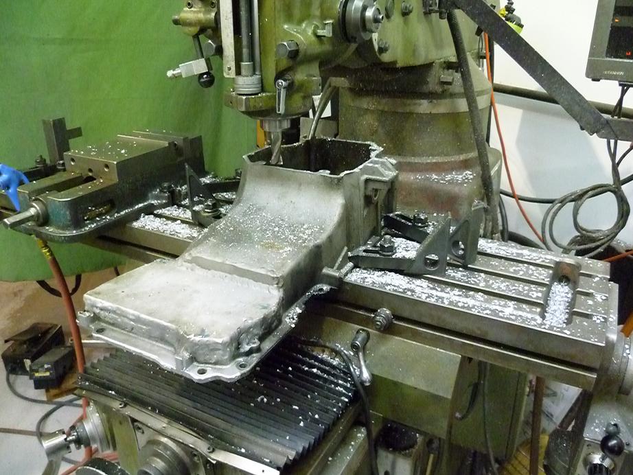
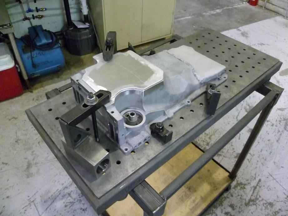
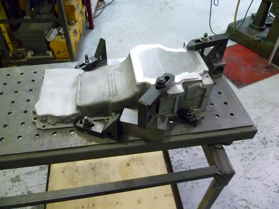
Powder coating & heat treating oven at work, figured might as well go all the way and pre-heat the **** out of the pan to minimize warpage as well as work some more of the oil out of the cast pan even though I already sand blasted & scotchbrited it...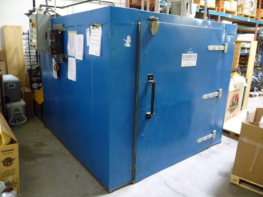
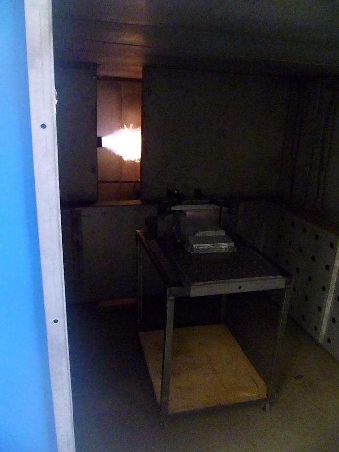
Welder at work did it this time, my machine at home has nowhere near the capacity running on only 110V currently...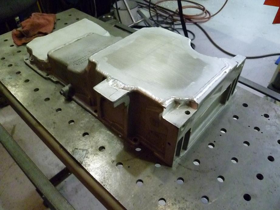
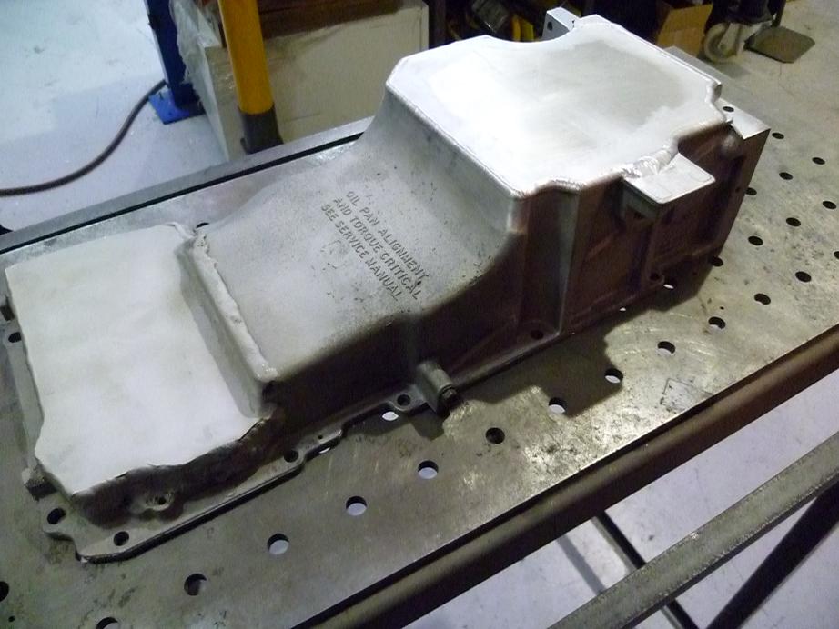
Still have to drill & tap for a drain plug & two oil return fittings (1 for turbo and 1 for oil breather/separator/catchcan).
6-4-2011
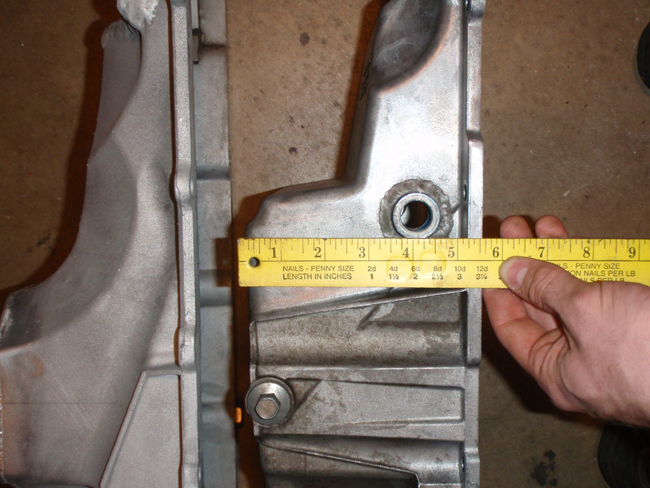
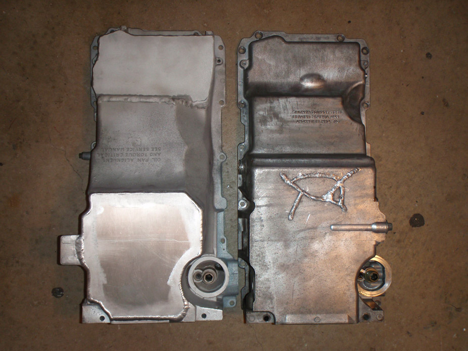
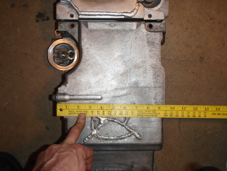
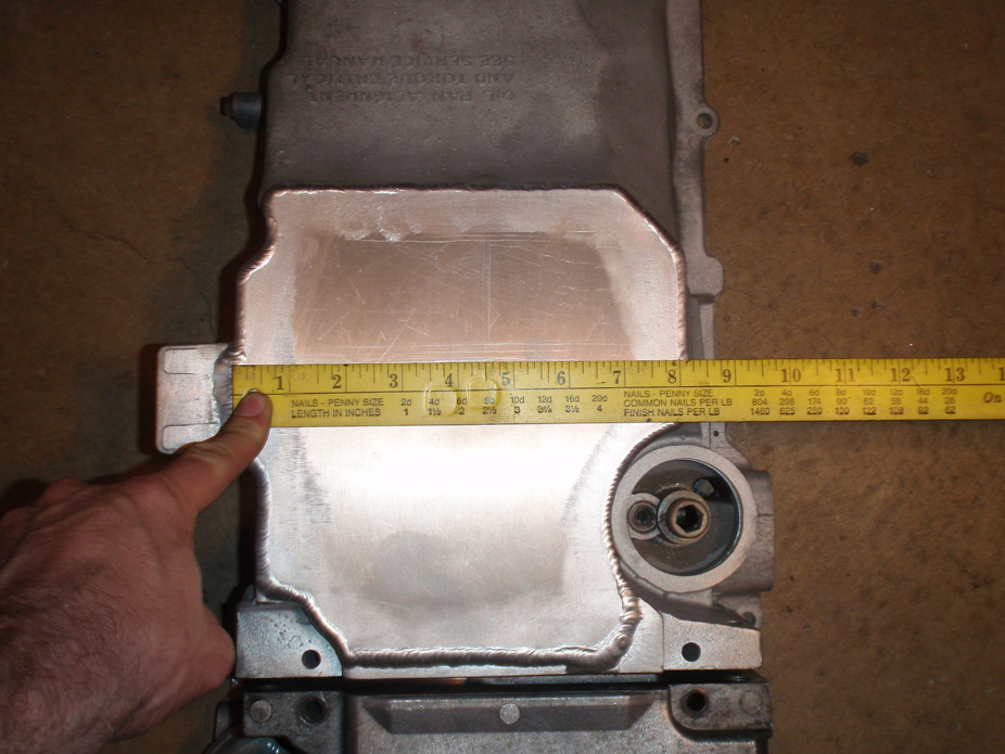
Oil pan stuff. I was too lazy to find the oil level sensor to plug my pan, and Mark's pan has, well, cracks in it, so measuring/comparing capacity didn't happen, but here are some comparison pics of my modded truck pan to a stock fbody. The one thing that concerns me is the level/height of the oil filter receptacle (better word for it??).
Sharpied area is what would still have to be chopped and removed to clear short idler/pitman arm assembly on my Nova, making my draglink stick out the furthest back from the crossmember. Sharpied area extends about 2" into the pan, towards the back of the pan.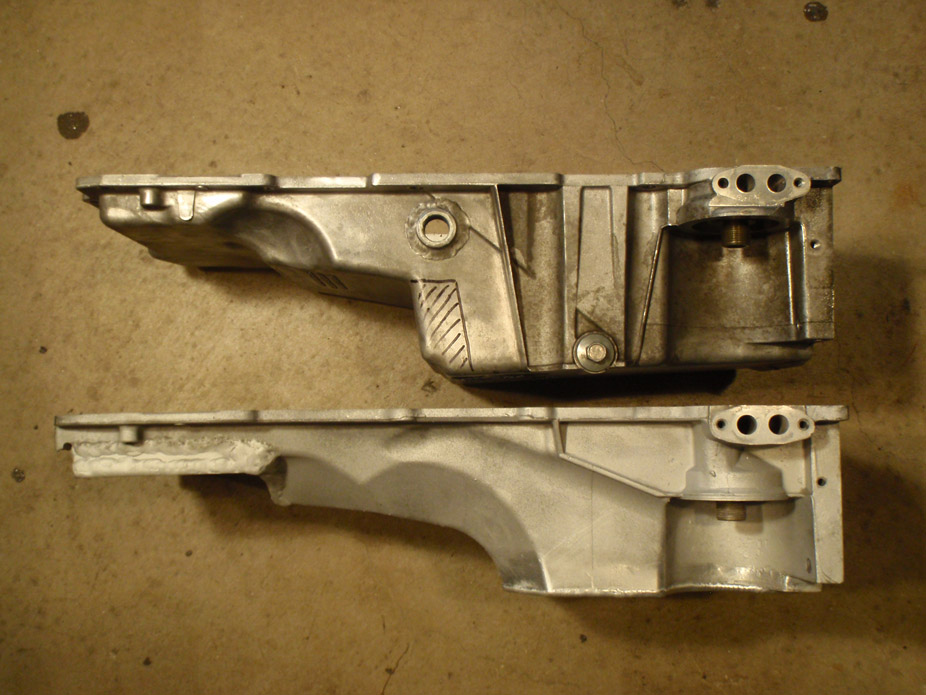
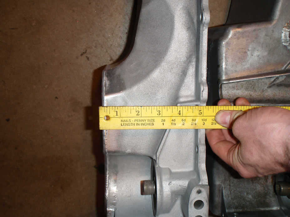
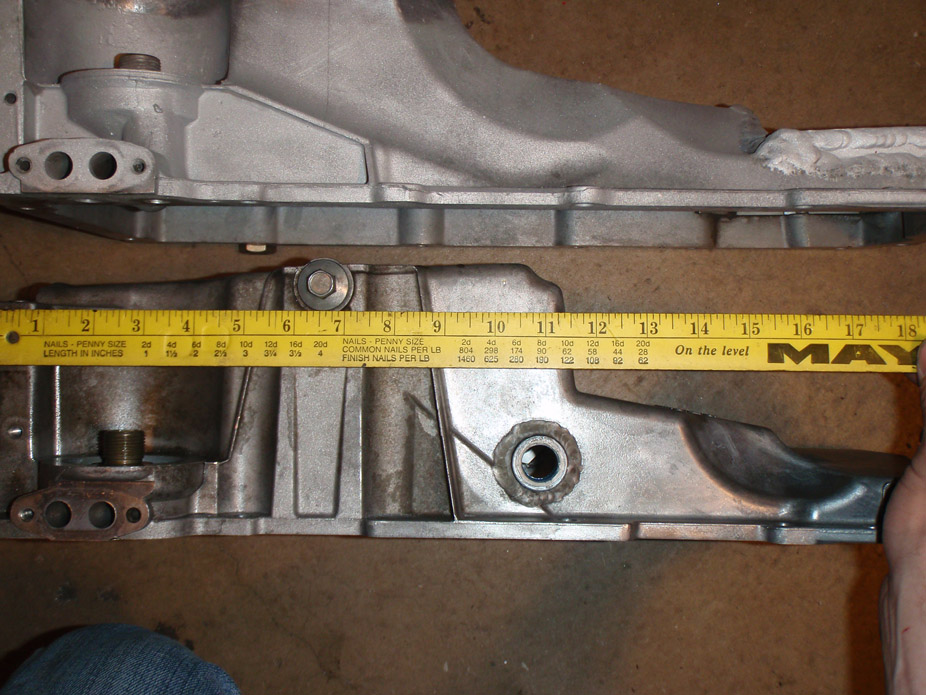
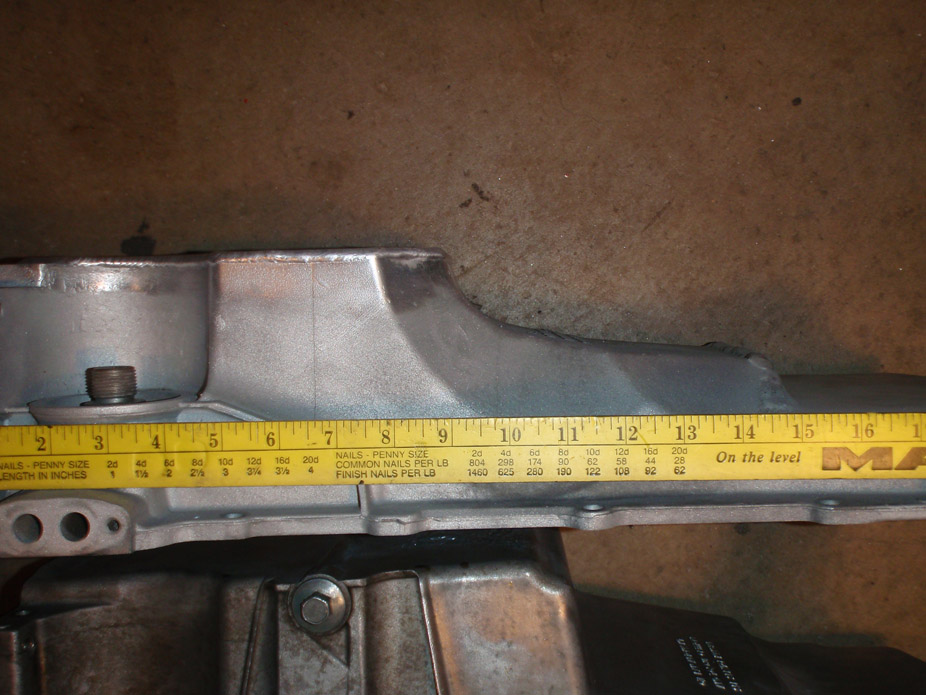
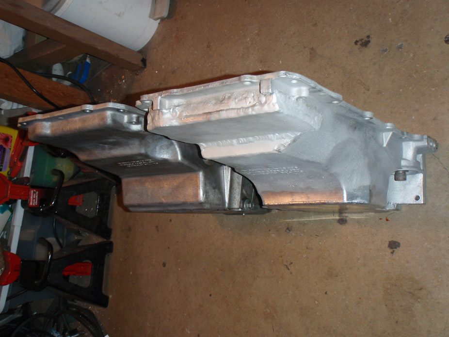
I modded the bolt-on tray thingy that keeps oil in the sump and made it more badass, probably gonna tack in a v-shaped baffle like the fbody too.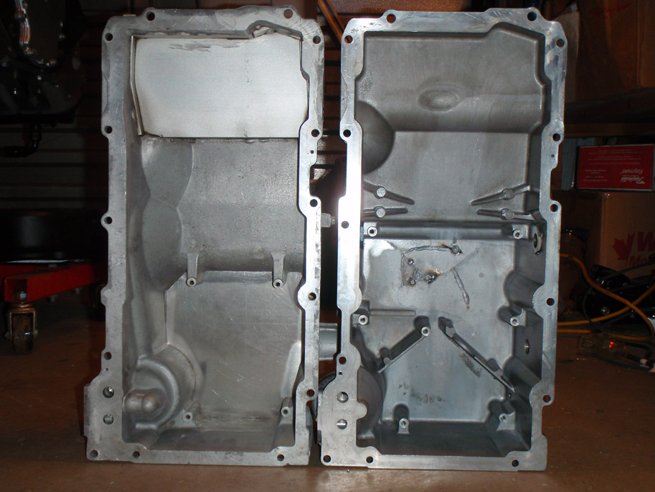
Flipped the driver side coil pack bracket to make all the coil packs "face in towards the engine" at the request of everyone under the sun haha. It doesn't look as bad as I thought it would with the coil packs' controller wiring on top.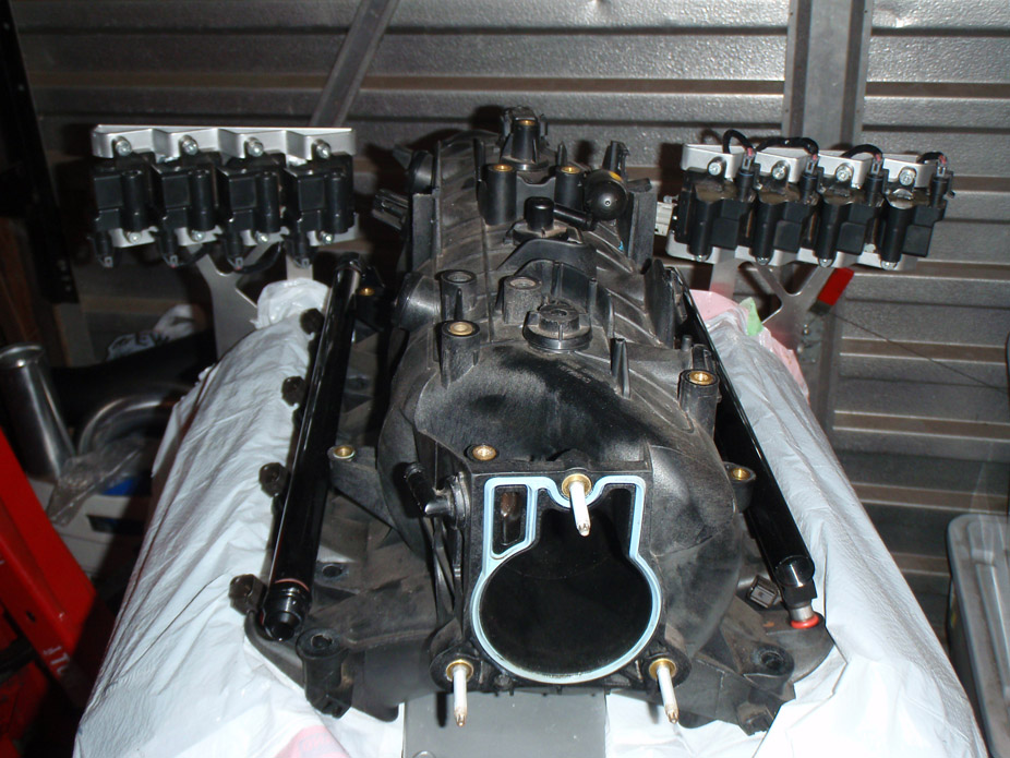
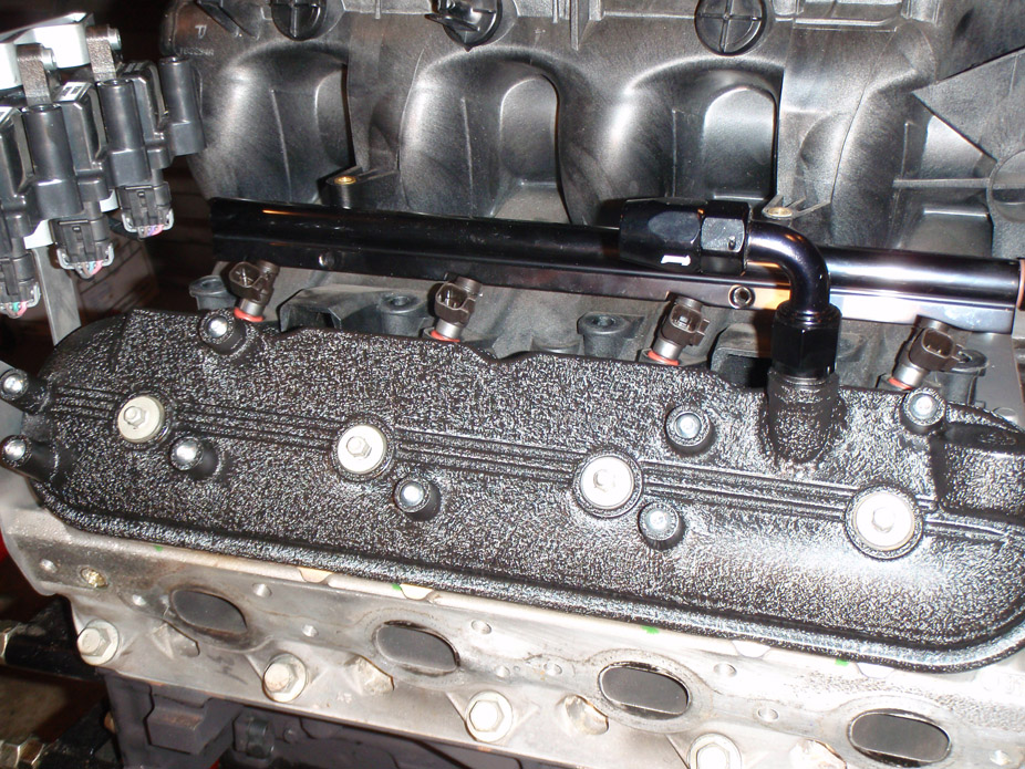
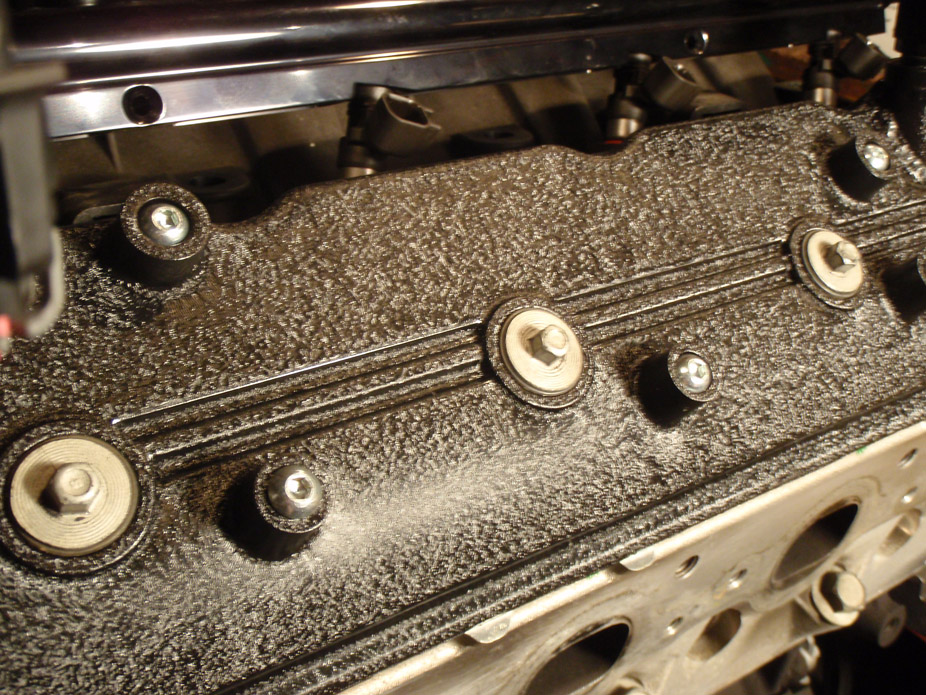
Always liked the crinkle paint look on valvecovers, dunno why, makes the engine look a little more different than normal. Pics definitely don't do the finish justice, the end result far exceeded what I was expecting out of a spraybomb can.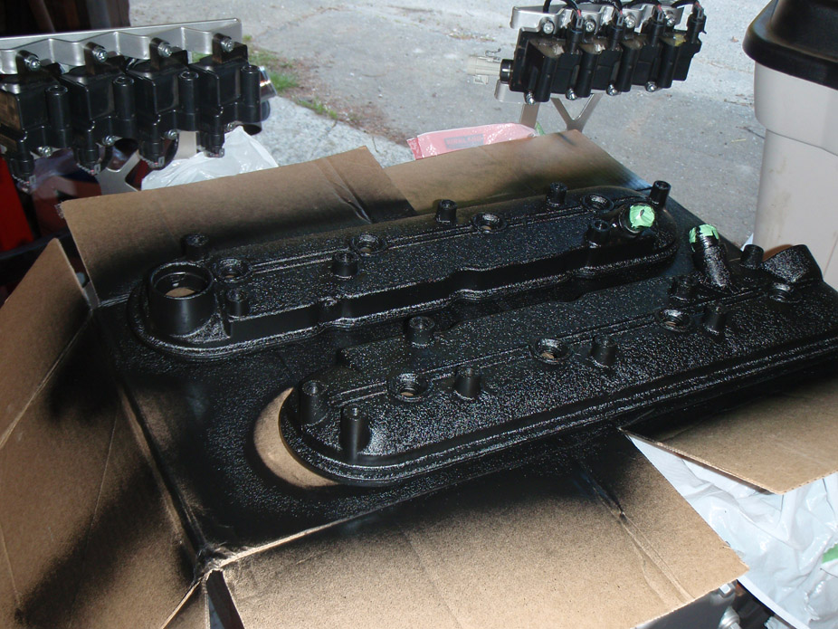
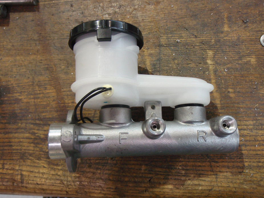
I didn't want to spend $240+shipping on a Wilwood 7/8" brake master cylinder that would be more blingy-looking than I want anyways, so went OEM (which I prefer the look of, call me crazy). After much internet searching, found a 7/8" bore aluminum M/C from an '85-89 Isuzu Trooper. Thing is super light and simple, functional looking... I like.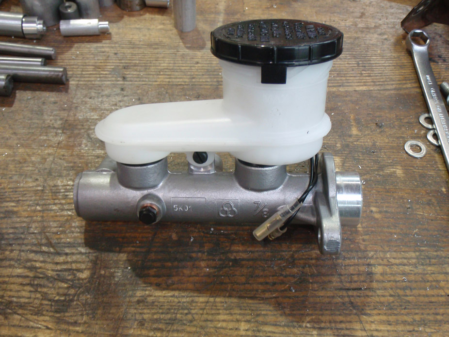
Supporting plate to go on engine side of firewall, to space the M/C out from the firewall a bit to give clearance to unscrew the reservoir cap, as well as to add rigidity to the enginebay side of the firewall where the brake pedal bracket bolts to the firewall.
Also has a pocket milled into it so the bracket for the combination/proportioning valve can flushmount behind it.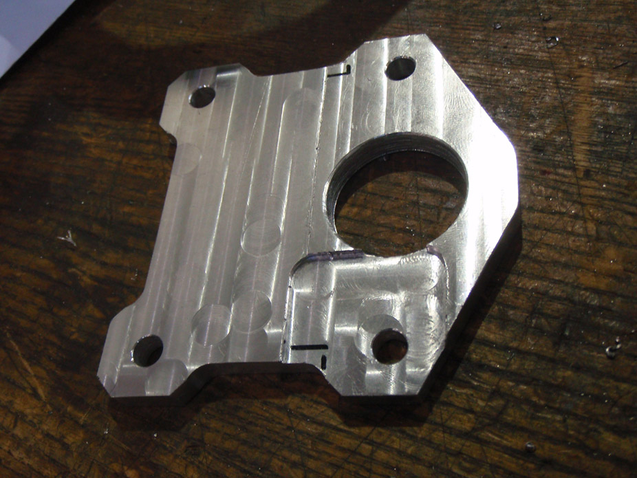
I'm cheap and think I threw out my old cast iron manual M/C, so I just made my own pushrod/clevis for the 240SX brake pedal. Clevis pivot hole is drilled so the bolt is a tight hand press-fit into the clevis, but the brake arm hole has a loose clearance fit so things rotate freely. The nut on the bolt bottoms out on the shoulder of the bolt before pinching the clevis giving everything nice easy rotation, and I also drilled a cotter pin hole so none of this jiggles loose and I loose braking connection.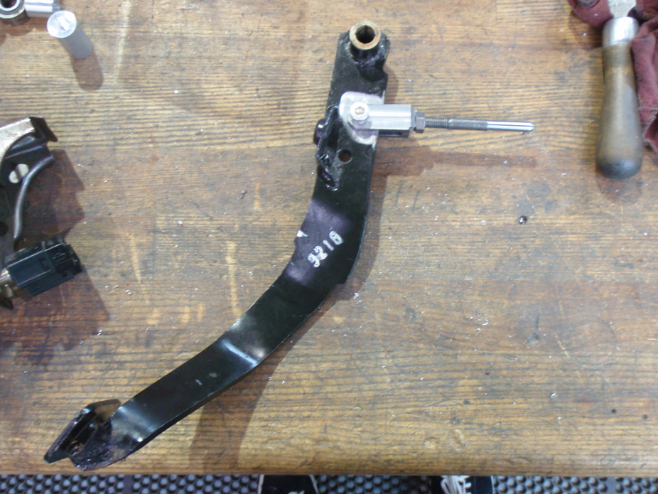
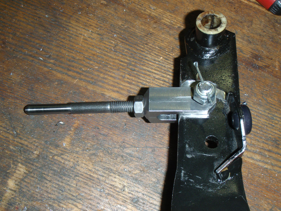
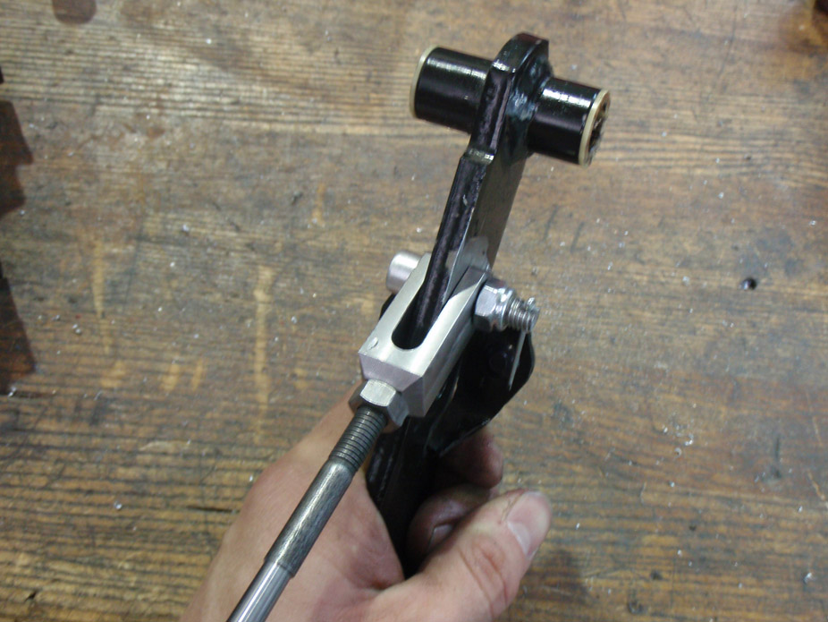
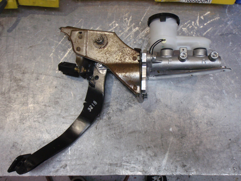
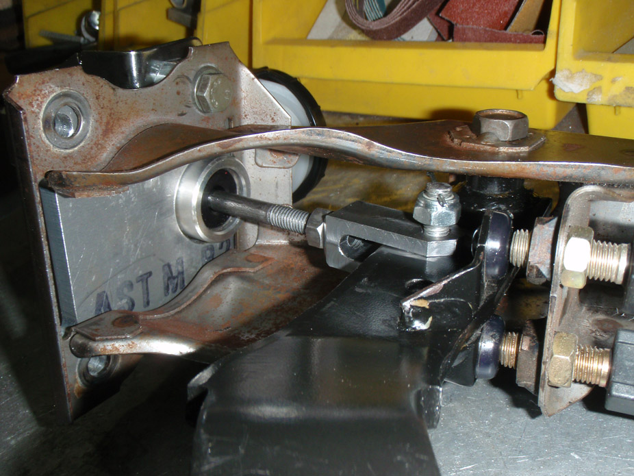
Clean, compact packaging with a non-descript raw aluminum look.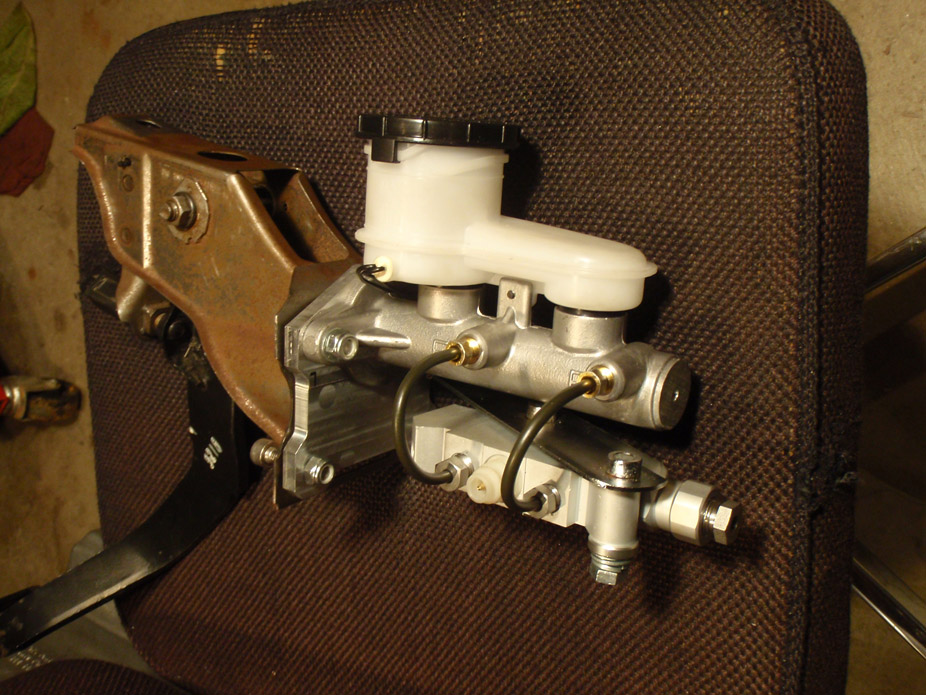
6-5-2011
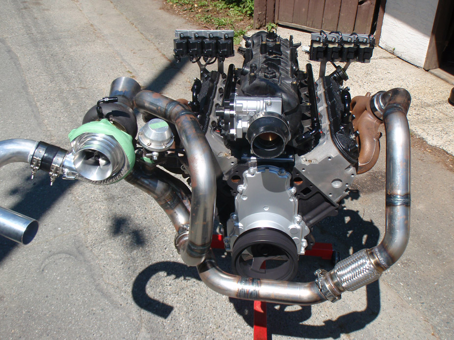
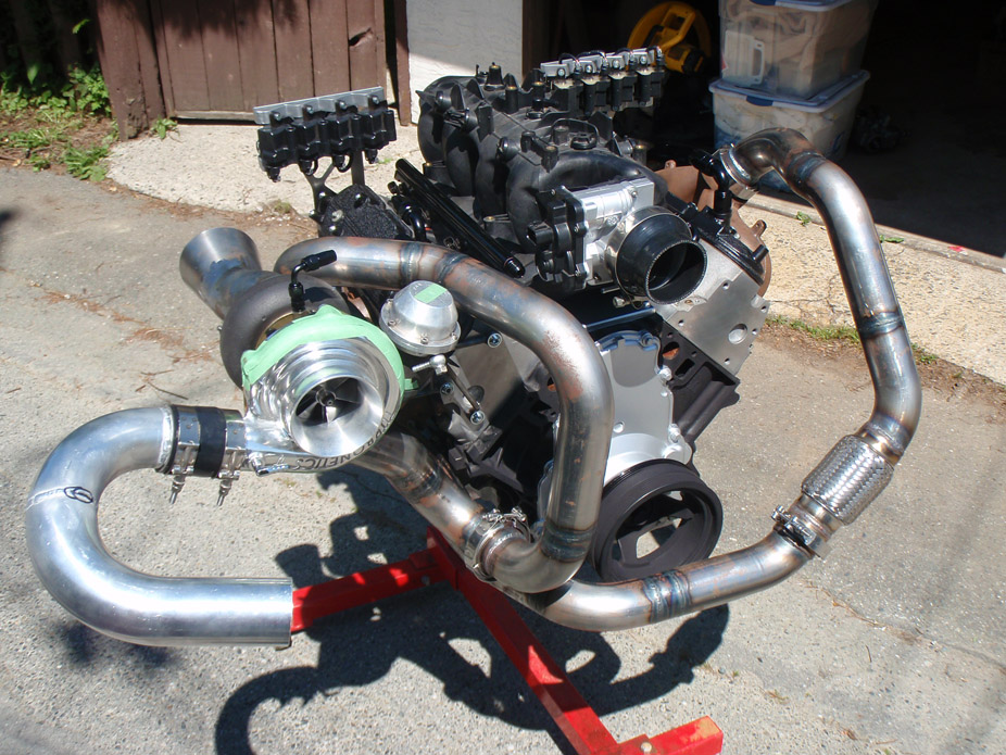
It was a sunny day today so I took the engine out for a walk. Still have to ceramic coat the hotside pipes...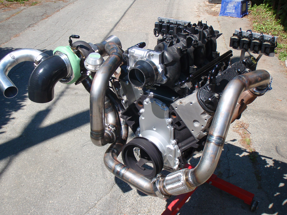
6-8-2011
Wastegate dump pipe flange, the final missing piece that was needed for me to finish up all the turbo piping. Tapered hole to go to a larger 1.75" pipe that will merge back into the turbo downpipe..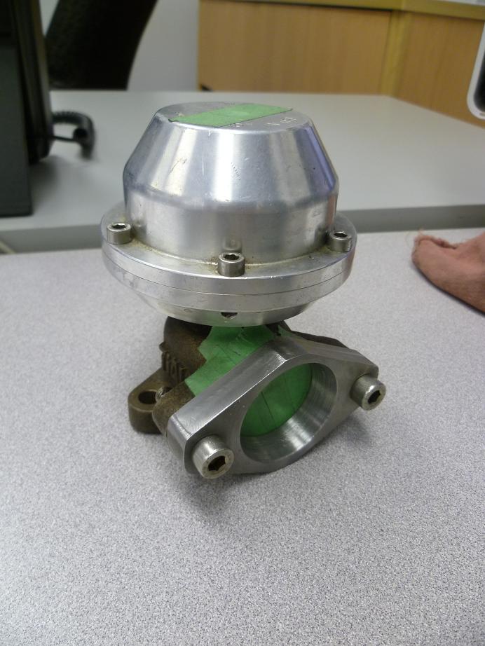
6-10-2011
O2 bungs. Guess I might be taking this "make it myself" thing a little far, oh well it saves money.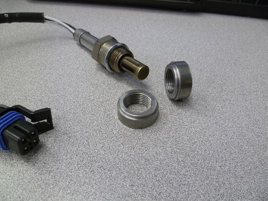
6-19-2011
Good timing, I got something for ya... Haven't bothered updating because this entire week for about 3-4hours after work each night it's been the boring, bitchy, shitty, annoying work of making patch panels and welding up all the floorpan/firewall, but as of tonight it's all done! Just need to spend a couple minutes grinding the firewall a bit and then paint everything... about damn time in my opinion.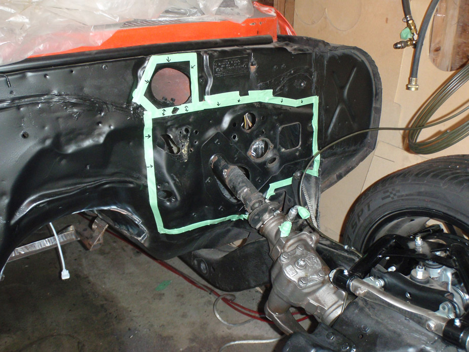
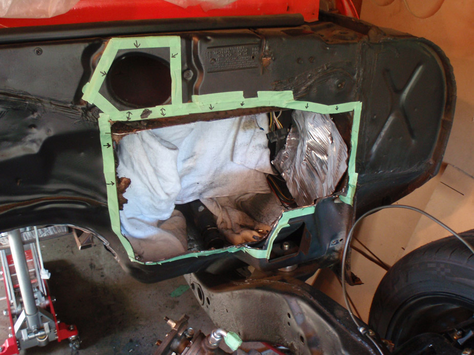
I couldn't resist mocking up the pedals even before I finished welding the backing plate into the firewall.
I've been wondering if all this effort will be worth it, and you all probably think this is extreme, but with my size 13 feet I've never found a car that I could heel-toe in because of the trans tunnel, not to mention the stock Nova pedals were way too far out from the firewall making my long legs feel cramped. Anyways it was totally worth it! all pedals are exactly where I want them, laterally, vertically, and depth-wise
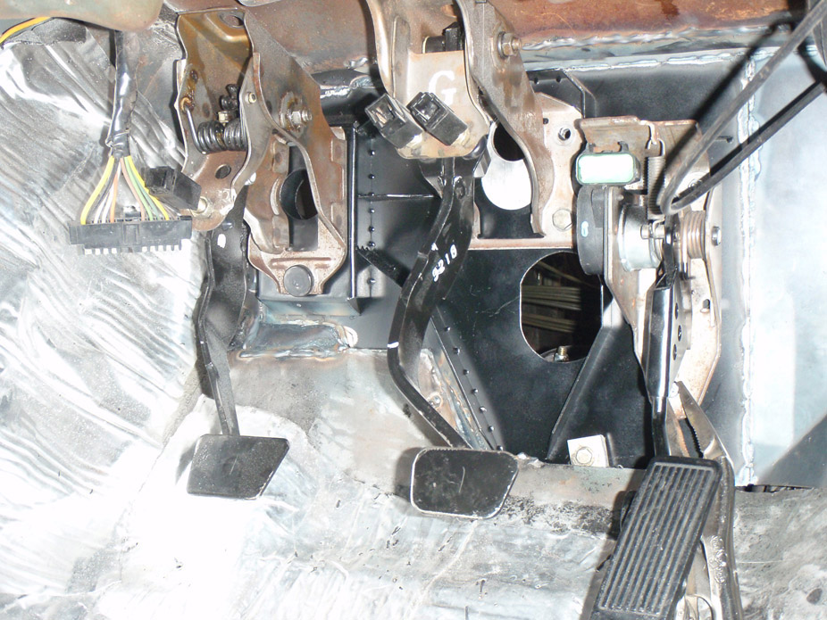
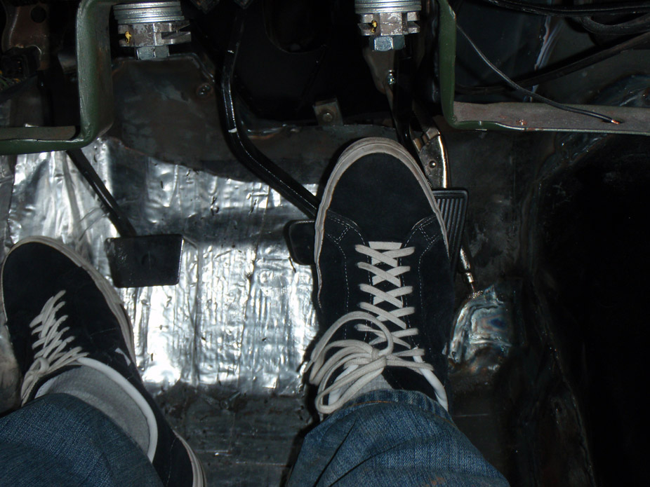
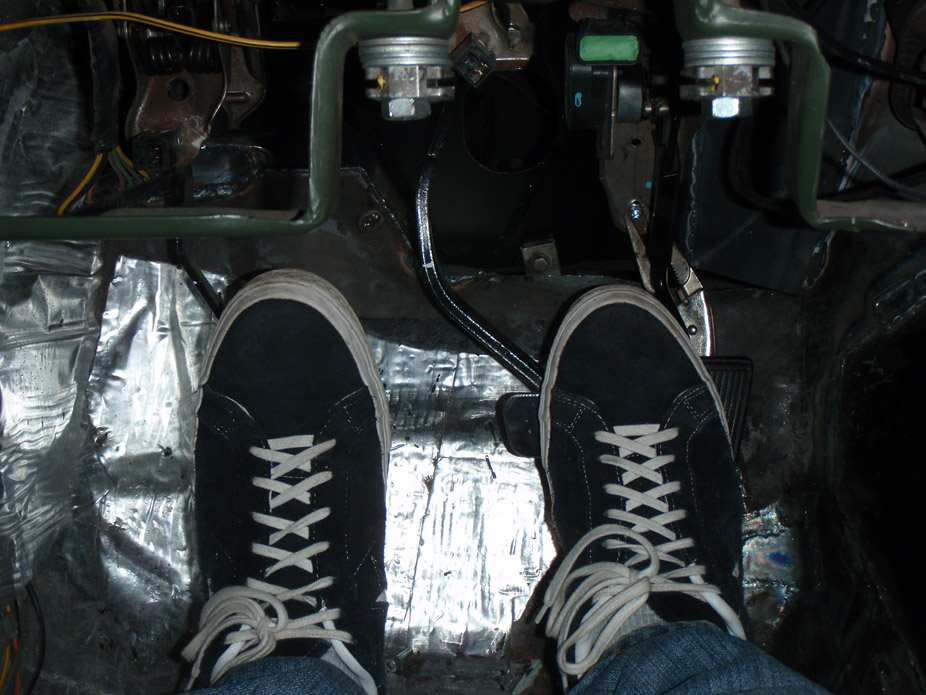
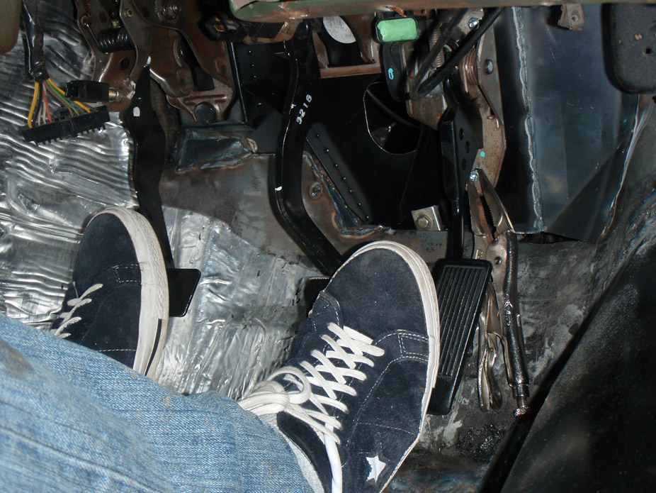
Also when it gets too late out to make noise I've been re-working the wiring in the car, eliminating all those useless buzzers, sensors, and idiot warning lights, as well as making sure the wires are safe and also wiring in connectors for the new gauges.
Before: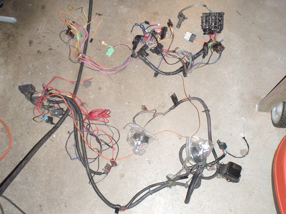
Are all these really necessary??
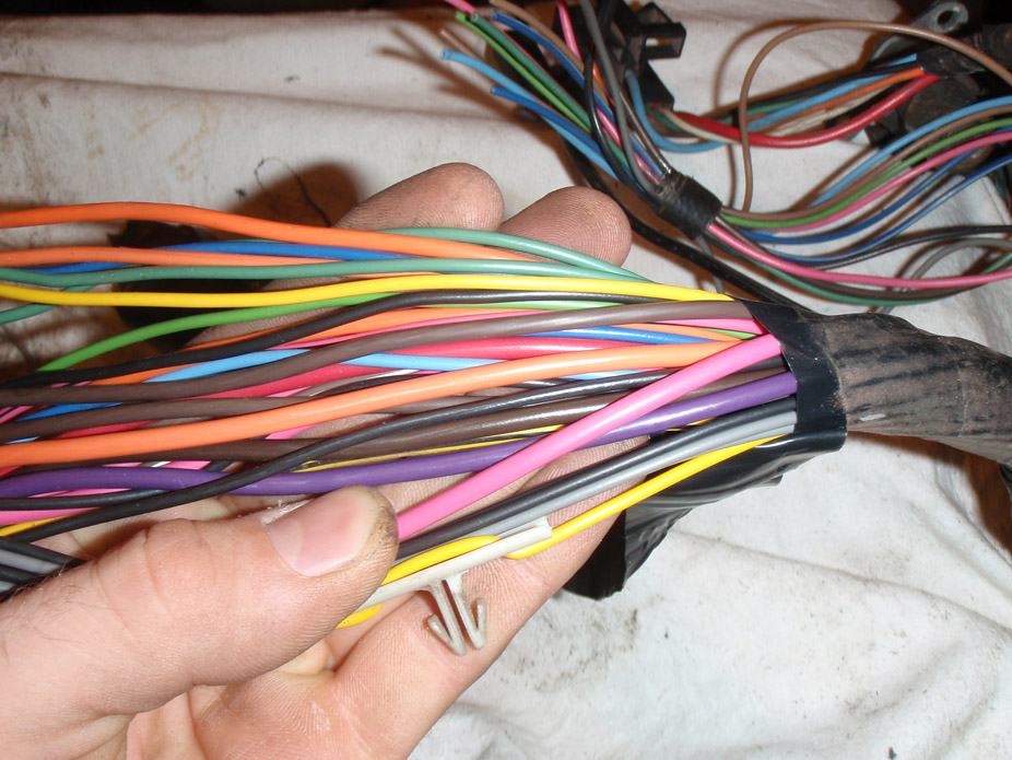
Apparently not...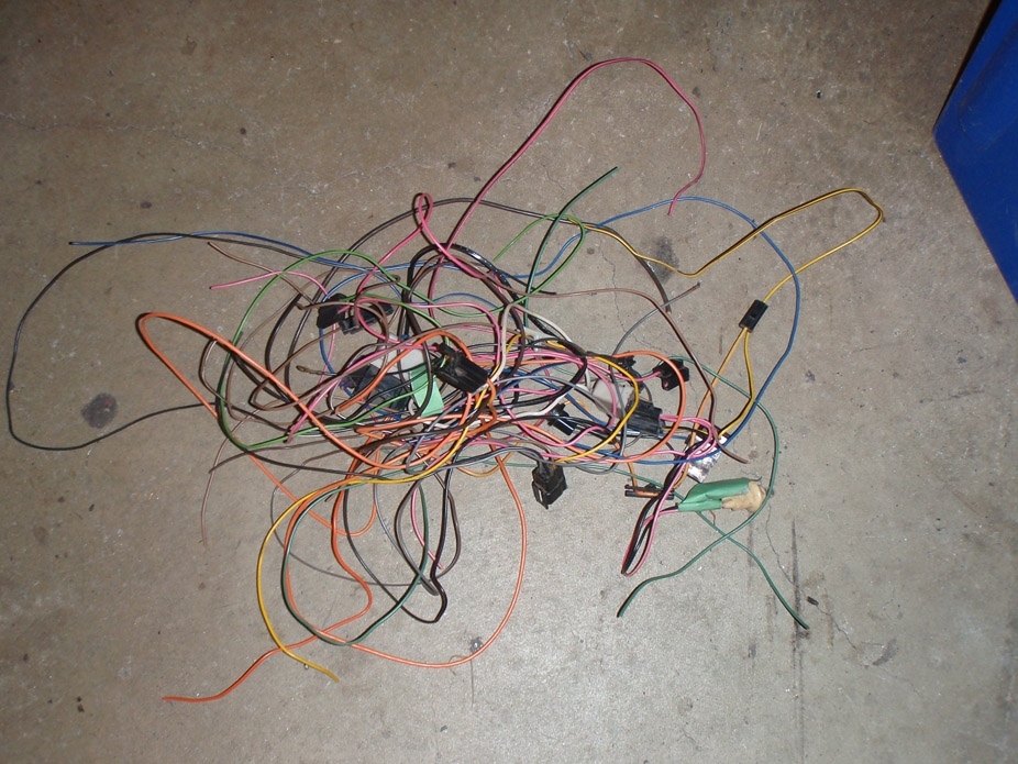
Simplified interior side of the wiring harness...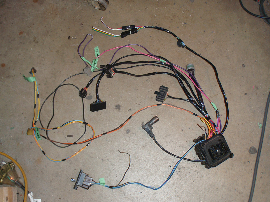
6-26-2011
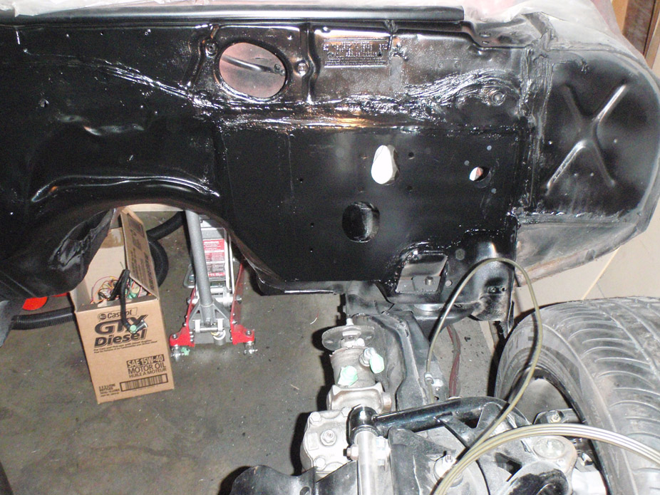
The firewall doesn't look fantastic, but I think it looks slightly "less bad" than it did before, just seam sealed the welds for the new plate so it ends up looking "factoryish", and the flash really exaggerates the seam sealer making it look horrible in pics...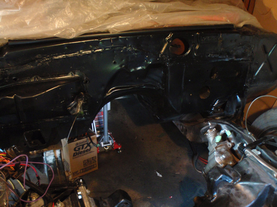
Just plumbed fronts for now...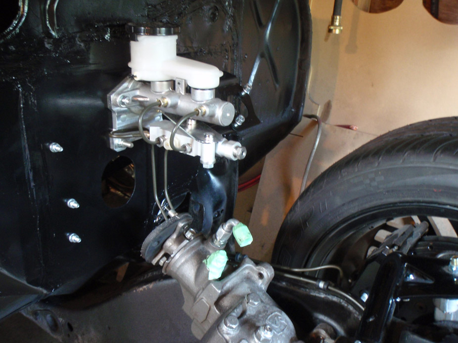
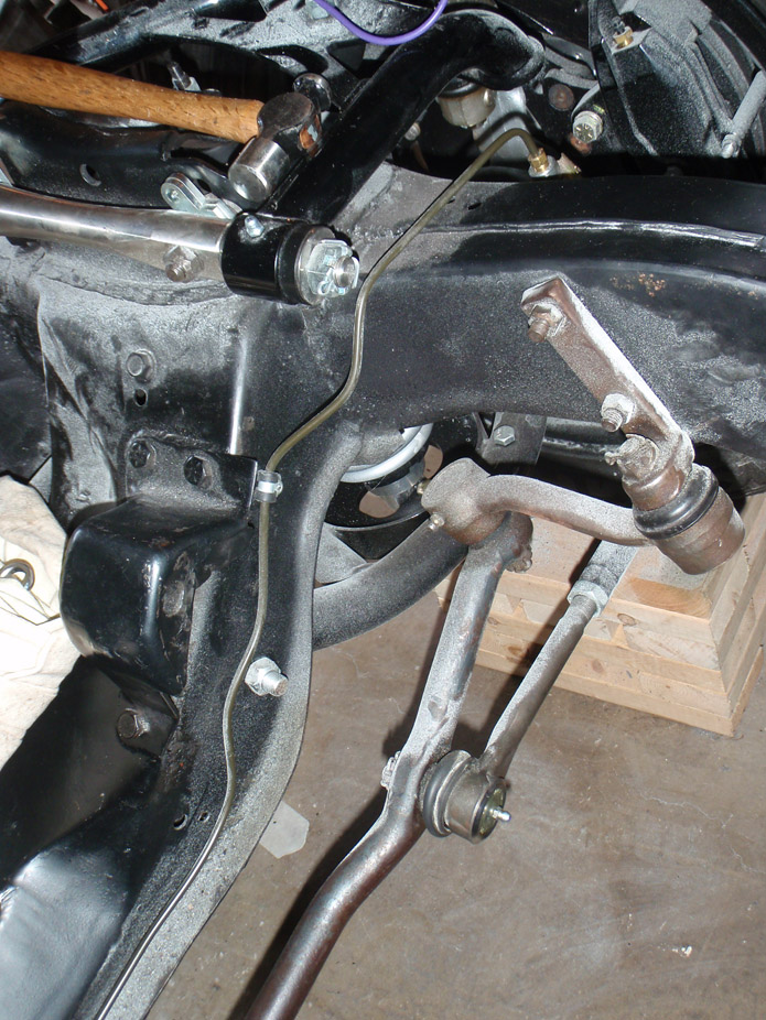
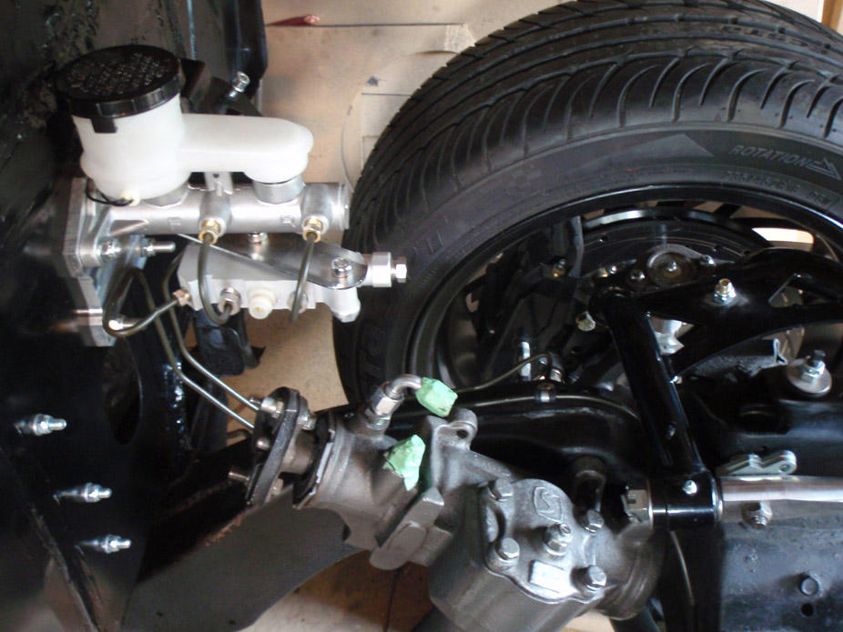
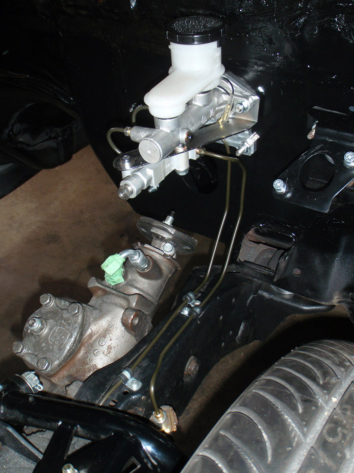
6-26-2011
With the front brakes/engine bay more or less wrapped up, and after a very annoying subframe alignment, it was finally time for...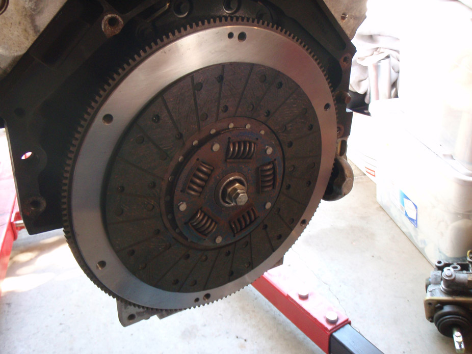
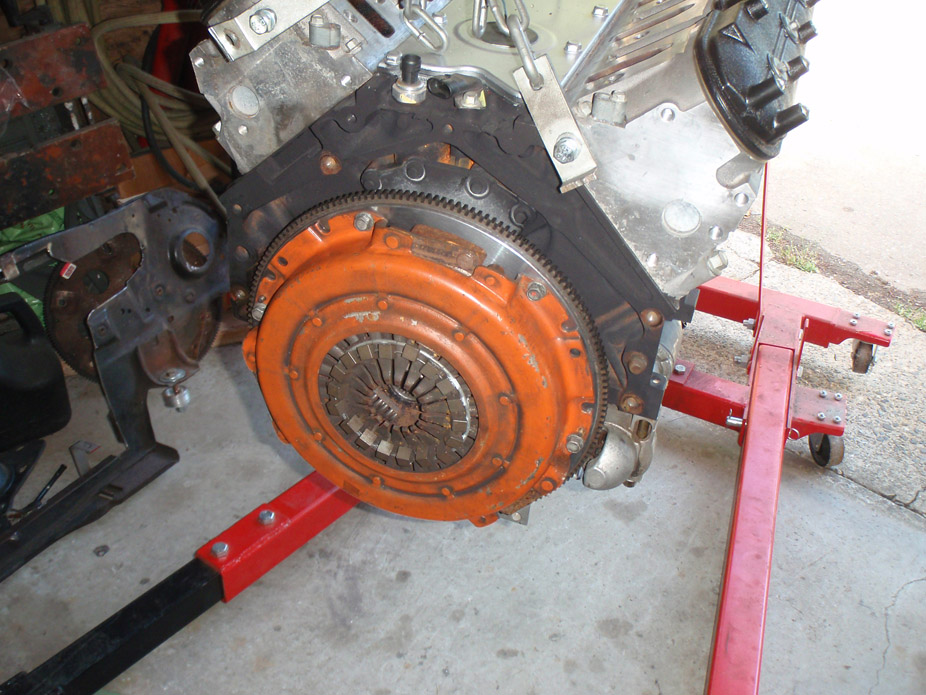
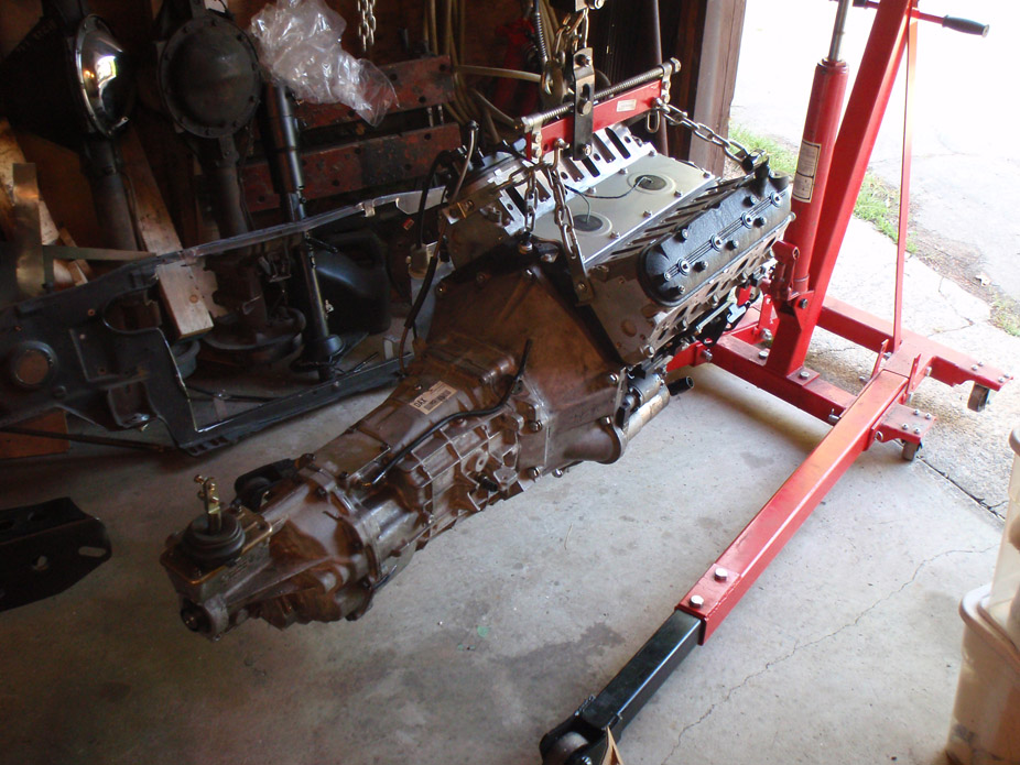
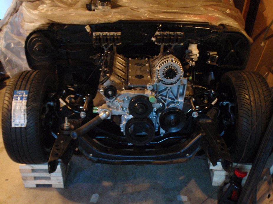
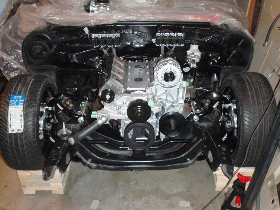
6-27-2010
Show must go on, even tho I'll probably need to take the engine out again for clutch mod/clutch hydro line lengthen.
While I have the engine in for final mockup, made lines for the Heidt's power steering pressure relief valve (to adjust "feel"). Knowing how this build goes, I'll probably end up not liking it and just get a TurnOne pump and fully re-worked box later down the road, but for now I just want to drive it...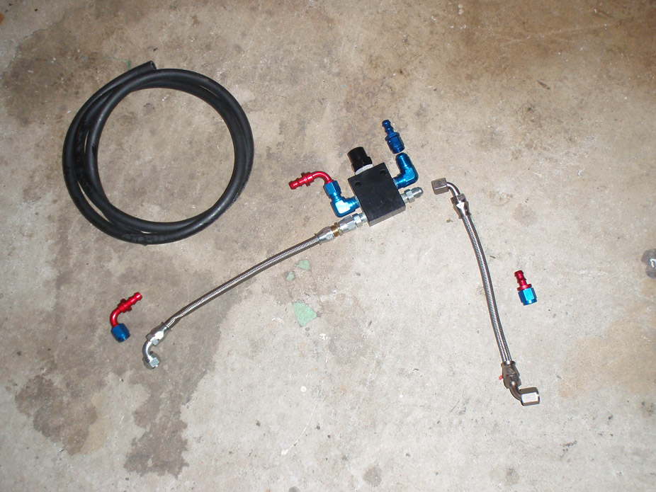
Red&blue will be sanded off and bracket I made will get painted, just mockup...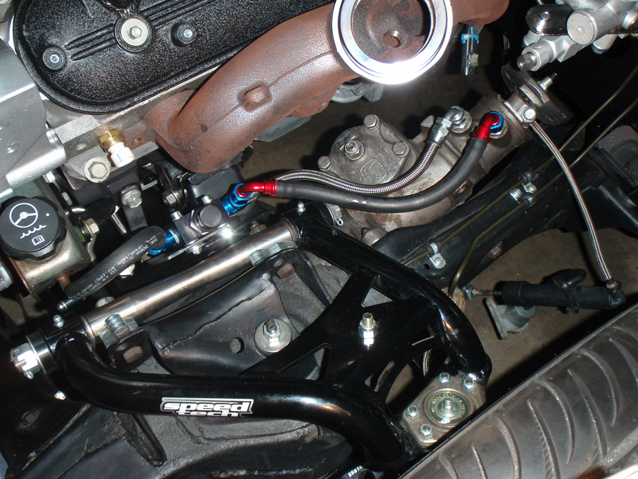
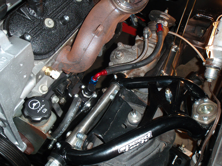
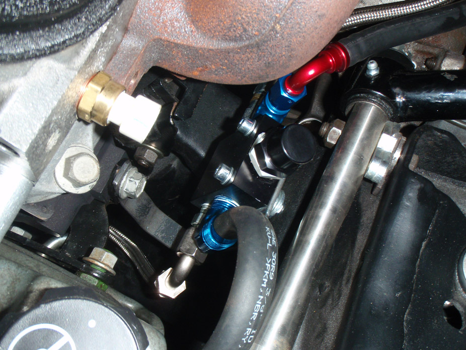
Annnnnd need to make the downpipe ASAP while the engine is in the so I can send the hotside off to get ceramic coated soon...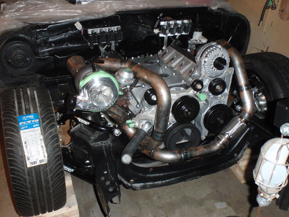
Good clearance seeing as I didn't have the physical idler pulley when first fabbing up the piping...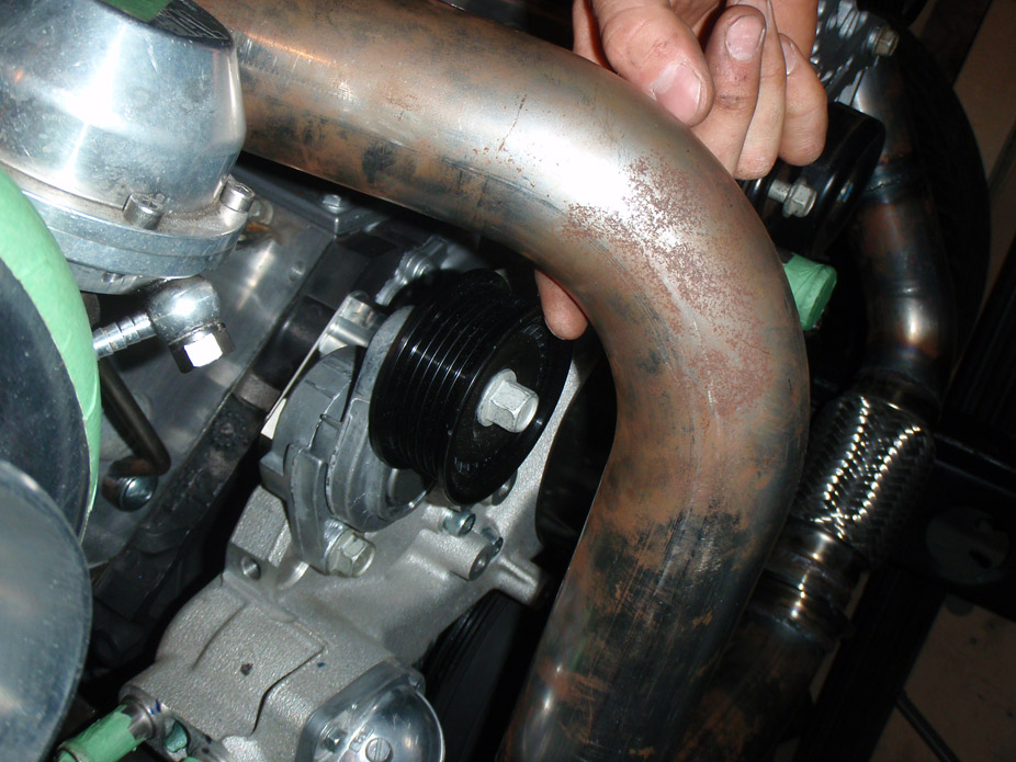
Wastegate dump pipe merging into the 3"->4" downpipe transition...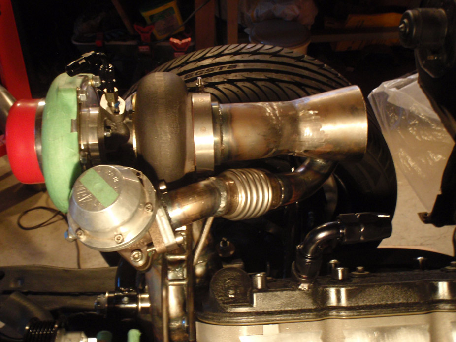
Tight but it fits with about 3/4" all round in there...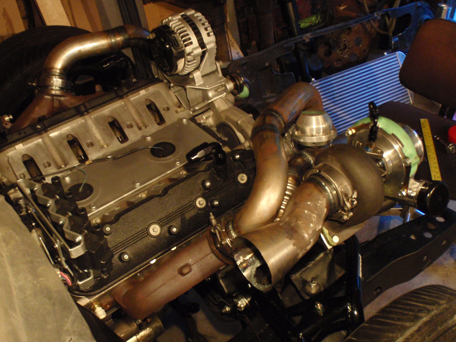
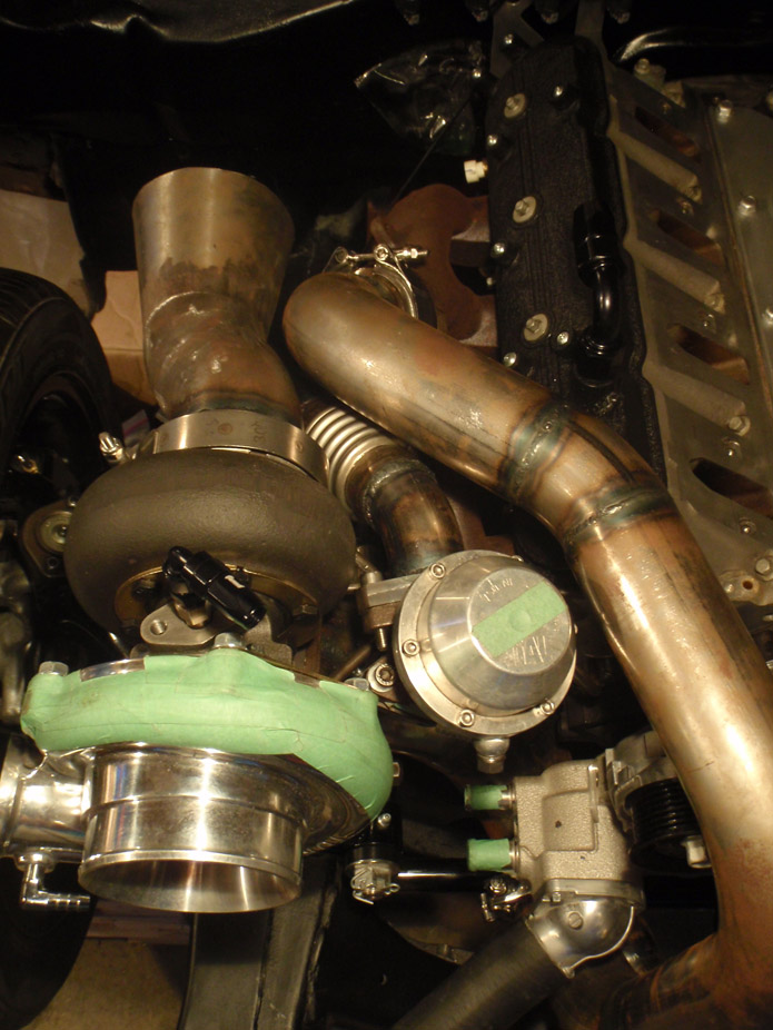
6-30-2011
I am NOT one of those guys!! I plan on "aggressively removing" those stickers via pavement slipping in the very near future....
I've decided I will keep the finger weights on... for now. Marktainium had the clutch before me and reported zero vibration or weirdness issues, so I will try my luck at it the way it is.
Plus I also don't have to pull the trans to lengthen the clutch hydraulic line... I conveniently completely forgot that there is the quirky quick-disconnect in there... engine is still in it seems for good!
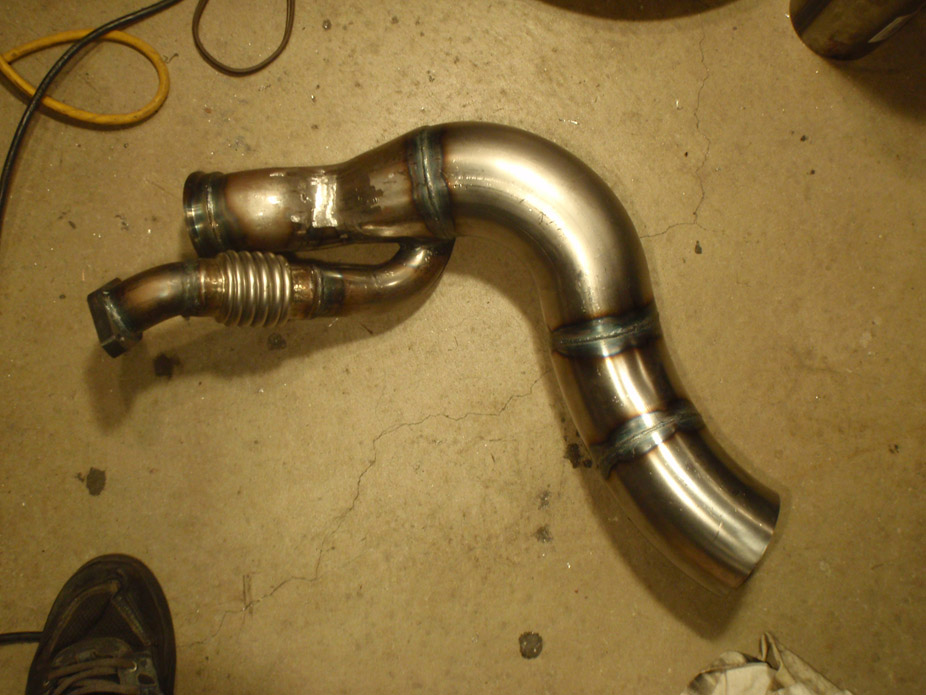
Downpipe completed up until framerails/floorpan, going to hopefully bang out a new trans x-member and y-pipe this weekend so that all exhaust things turbo related are ready to go to the ceramic coating place on Monday...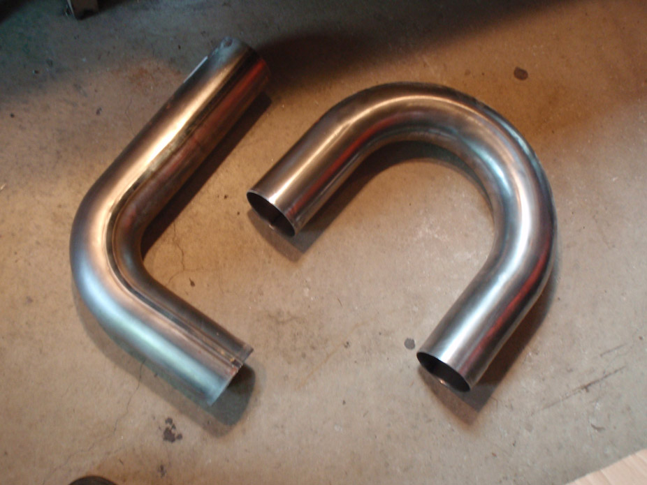
7-2-2011
Made some oil lines & location for the oil pressure sender.
Stock...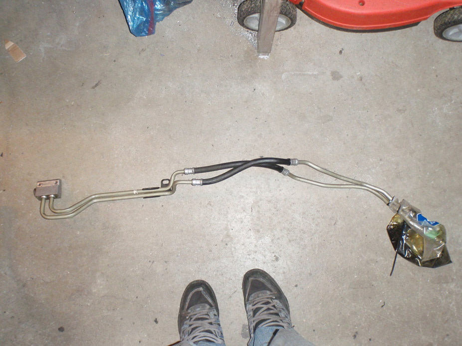
...modified stock to all I need...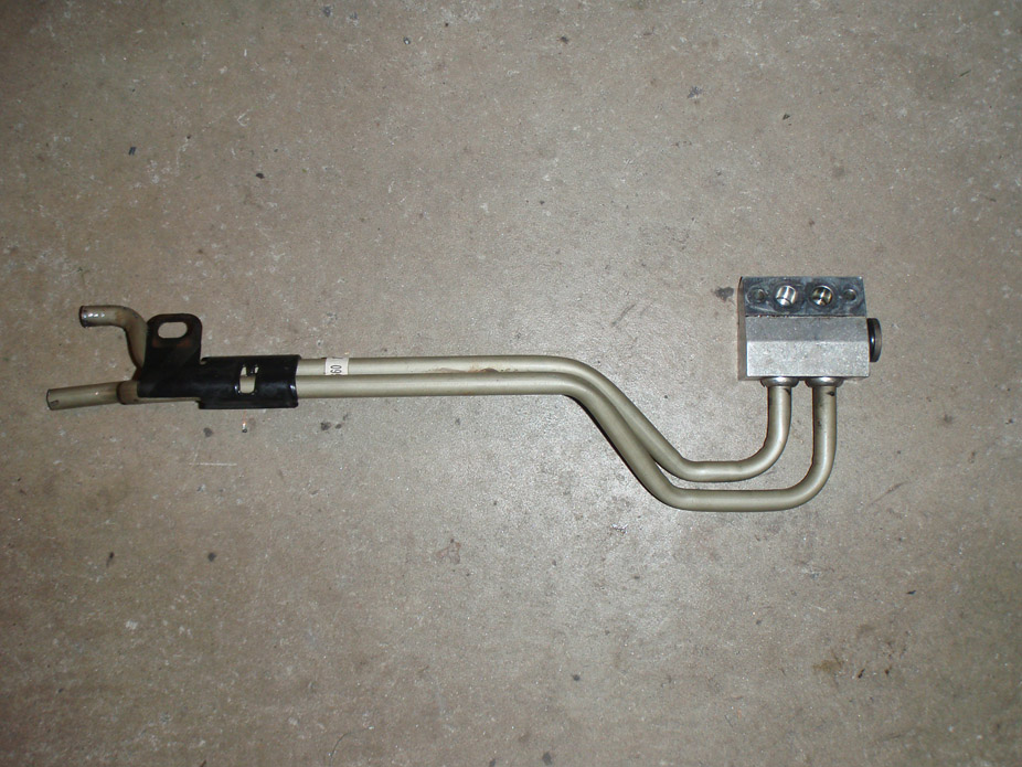
Location of pressure sender is AFTER the oil cooler, so that it reads the oil pressure that the engine block sees, and also would report pressure problems if oil cooler conks out somehow...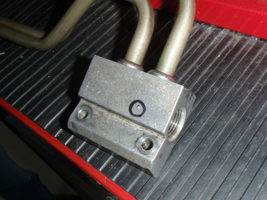
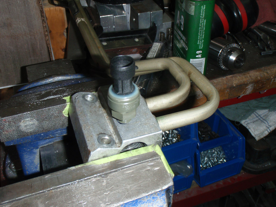
-8AN steel bungs welded onto lines, to have some flexy lines going to the oil cooler. Again, the TIG welder is so far the best tool I've bought by far.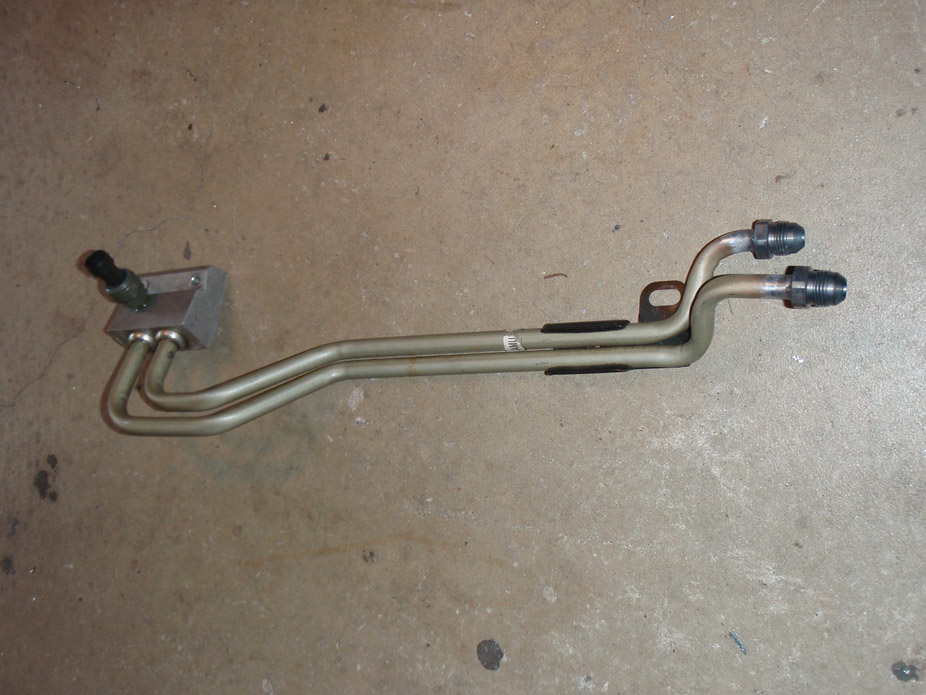
So.... transmission cross-member version 2.0. Not that there was anything particularly bad with the first one, but since making it I've welded the floorpan completely flat (eliminating the ~0.5" humps to clear the stock trans x-member) as well as remove the subframe bushings, so old x-member would need modding anyways.
And it was kindof flexy, but not in a dangerous way.
And it had a lot of 90 degree features that didn't look the fanciest.
And it was MIG'd so it wasn't the prettiest. Like everything on this build, the first time is a new part of the learning curve, and I wanted to redo, so I did.
First step was to make a reference point for the lowest that anything could hang, be it x-member or exhaust pipe, which is represented by the top of the 1"x2" clamped in there...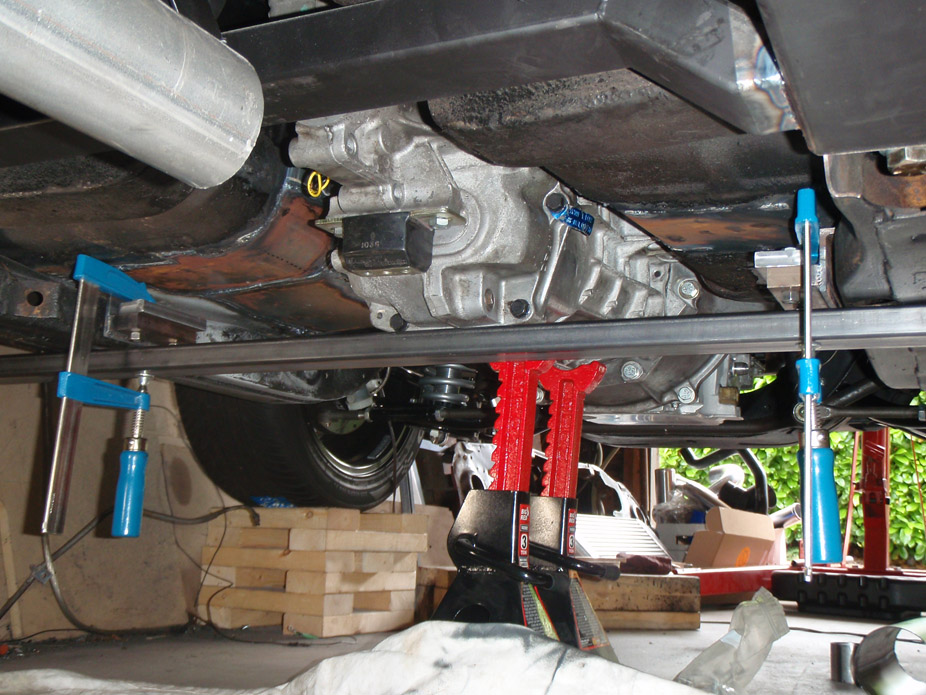
Benchtop vice & hacksaw mitering is very classy..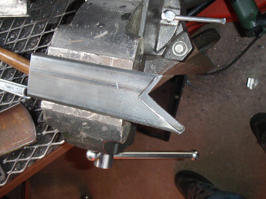
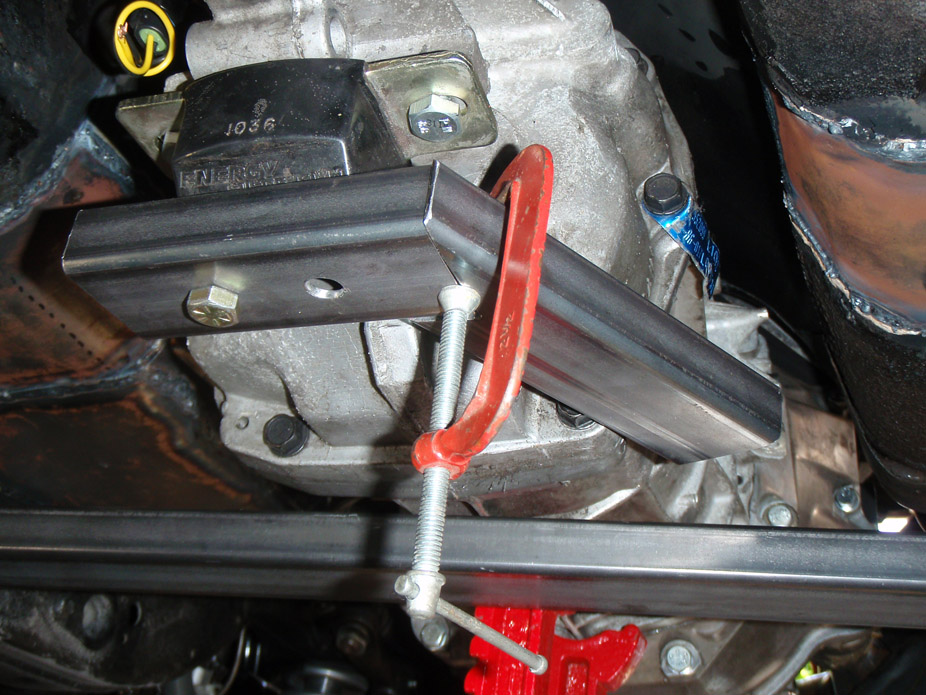
Decided to make a dedicated turbo x-member this time, but still have clearance for dual 3" pipes to not hang below the subframe rails (tall order without subframe bushings)...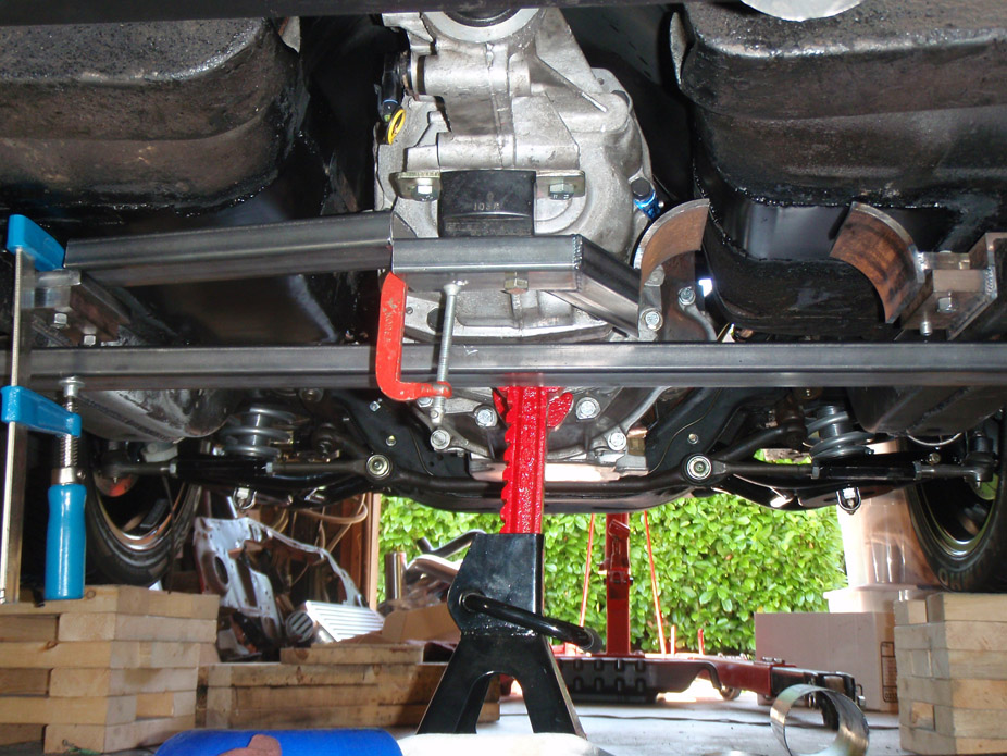
More fancy smancy mitering & stuff..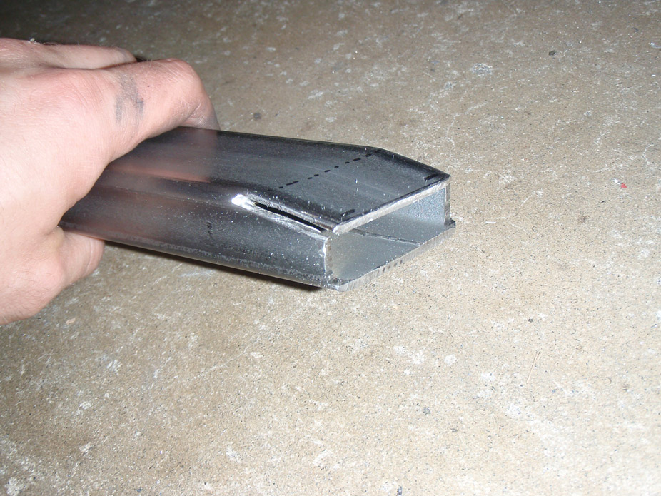
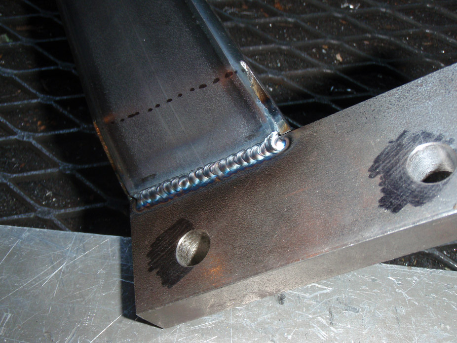
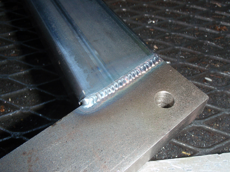
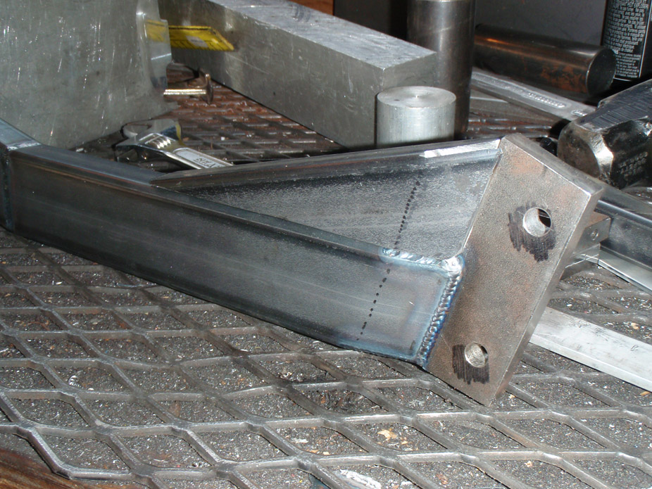
If there's ONE thing I've learned from all this car welding and machining/jigging at work, it's clamp clamp CLAMP...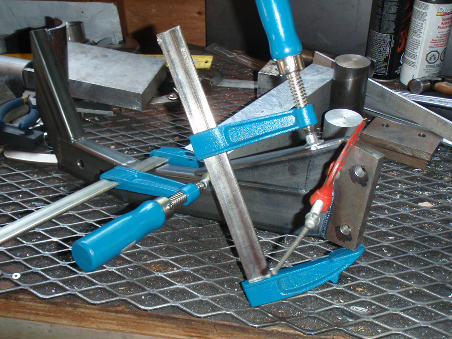
Results should be pretty self explanatory...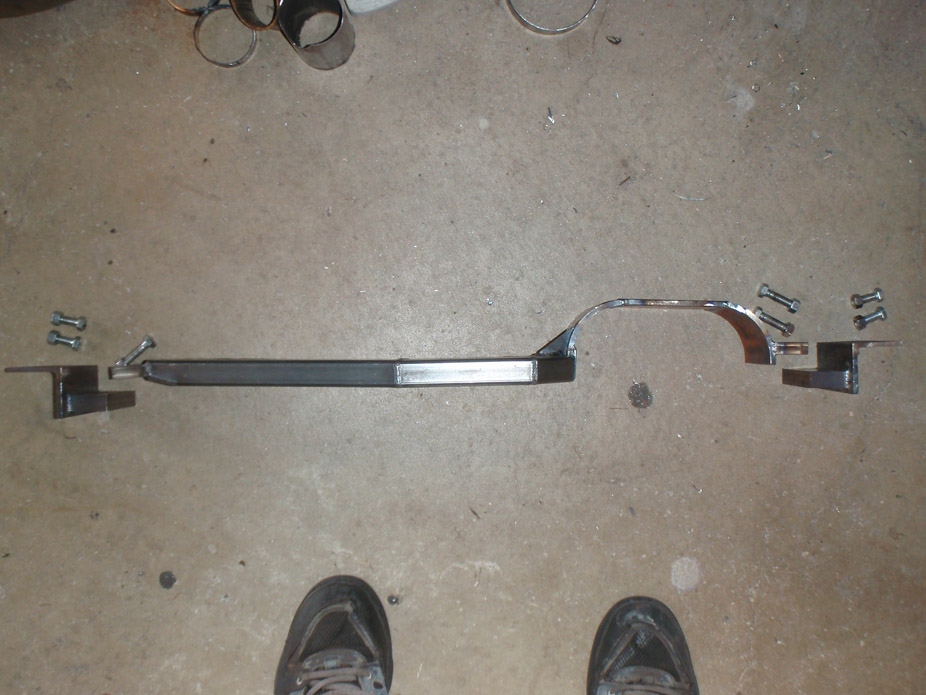
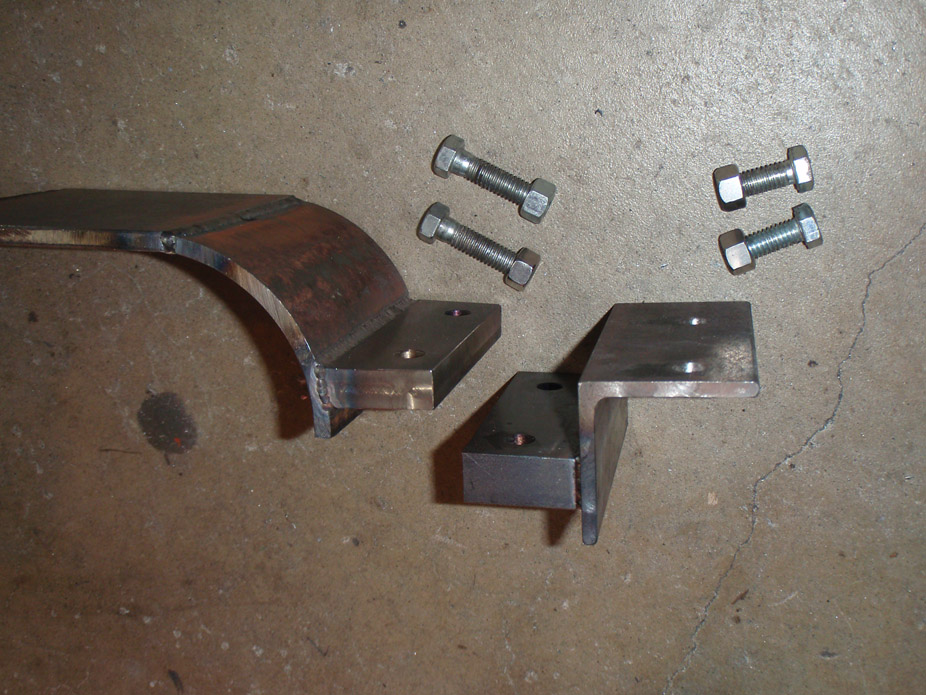
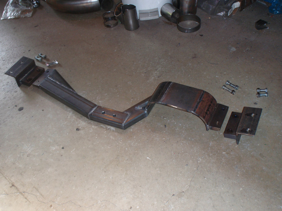
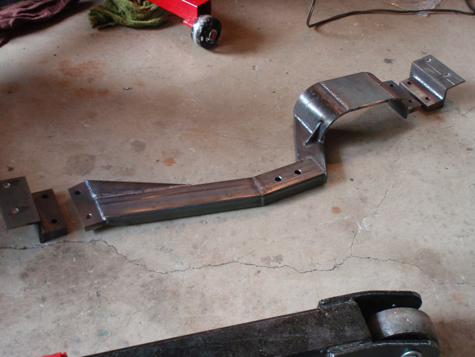
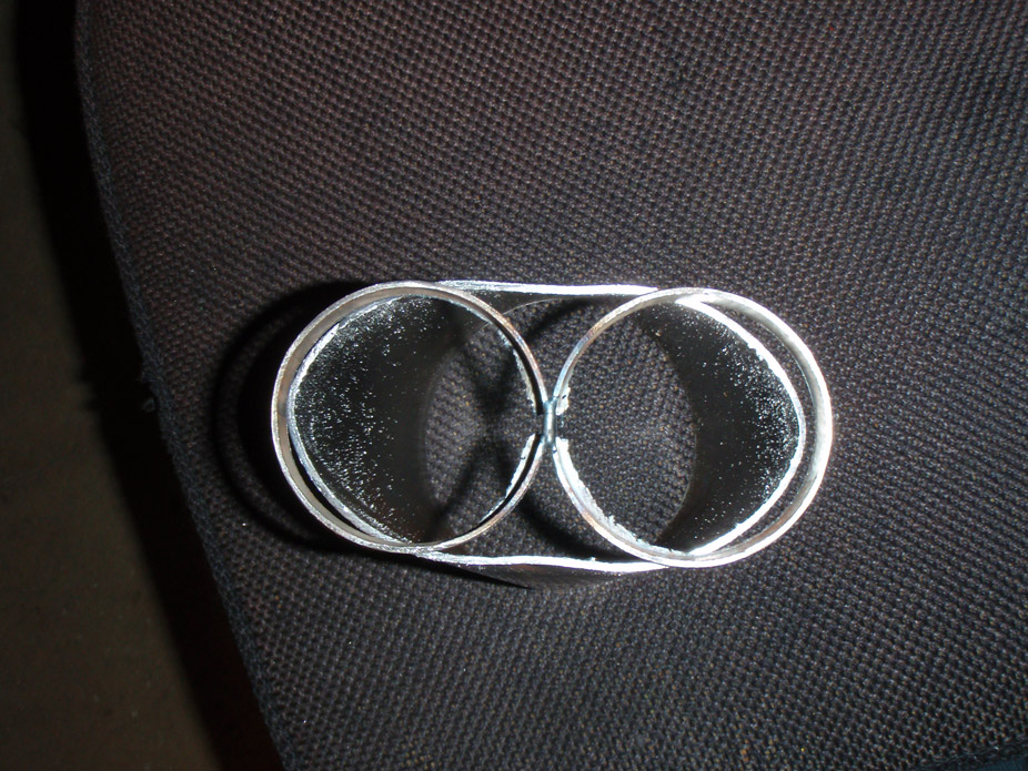
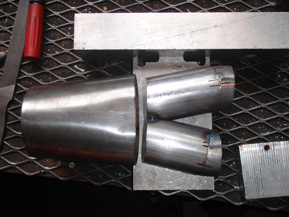
Turns out there's good ground clearance with dual 3" pipes, but a 4" single would slightly hang below the subframe rails at that location, so aim is to have the single 4" -> dual 2.5" split before the trans x-member.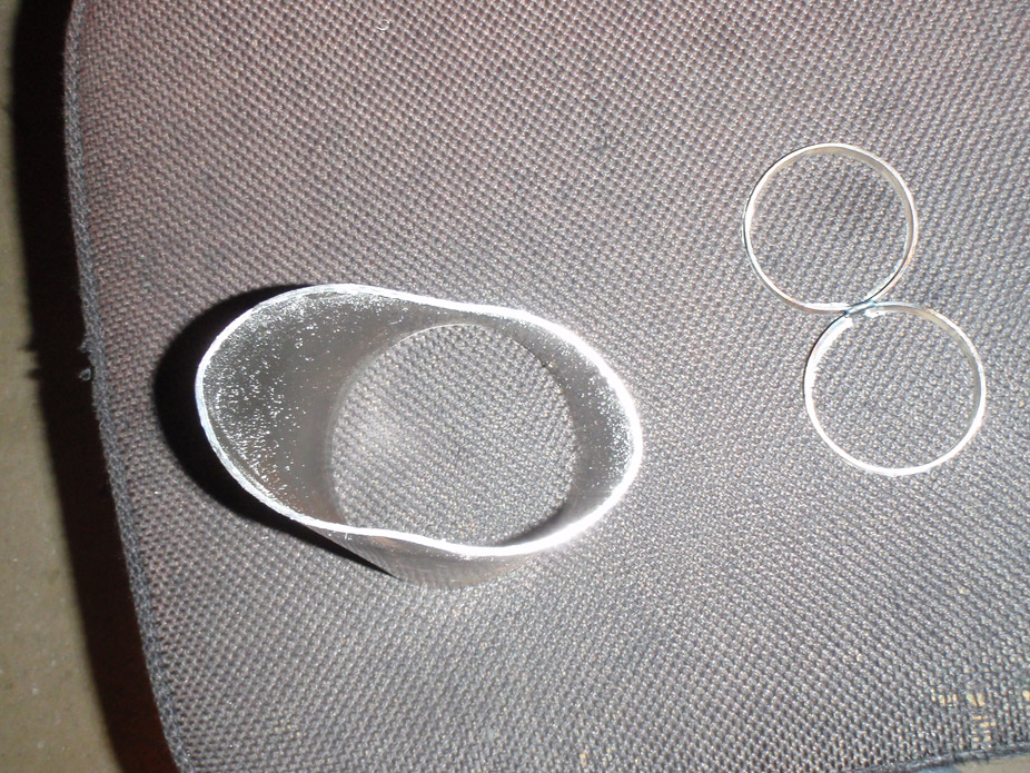
7-15-2011
It turns out when I was mocking up my panels and adjusting the cowl support, it has to be modified and that meant the hood would close at a lower height to close properly, and there ended up being interference between the alternator and the hood.
And I needed to find a way to bolt up an idler pulley between the alt & p/s pump to give them both more belt wrap, so why not kill two birds with one stone...
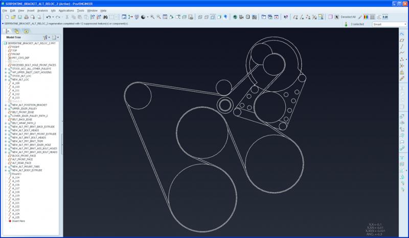
Two belt wrap options are possible with the alternator relocation bracket I came up with, but I will be going with option #2. The two circles at the top right are the alternator pulley before & after, ended up moving down 1.5" and over 1"
Option #1: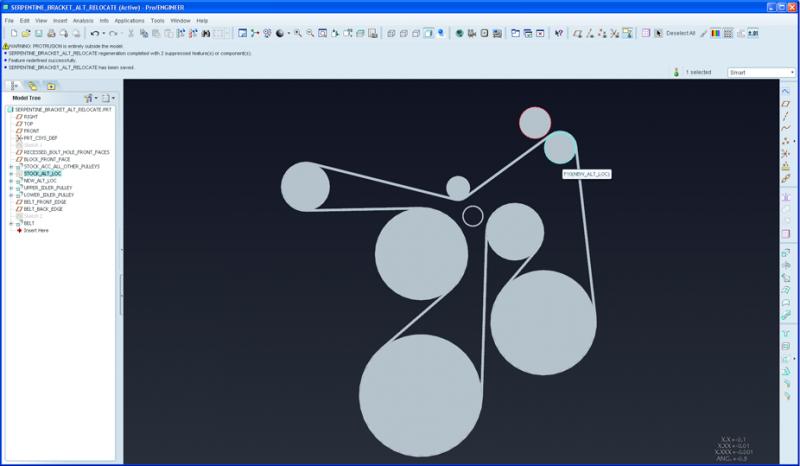
Option #2: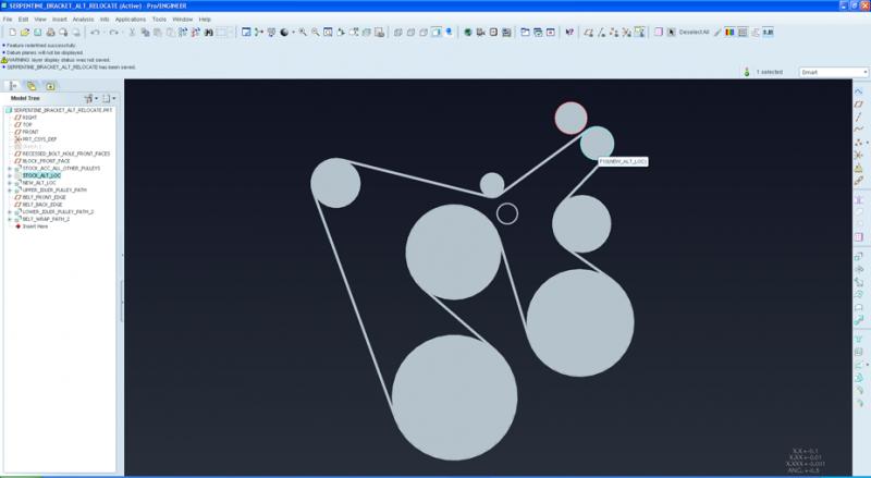
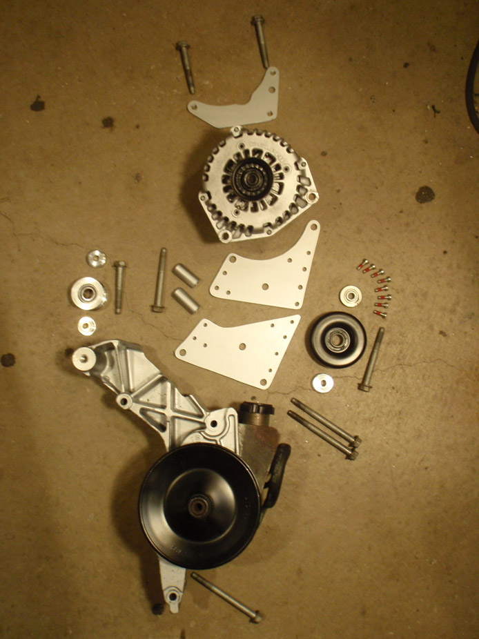
Wanted to reuse the stock bracket mainly to reduce the amount of stuff I had to make (extra fab'd bracket for p/s pump) and also to retain the location of the stock truck accessory idler pulley (top left).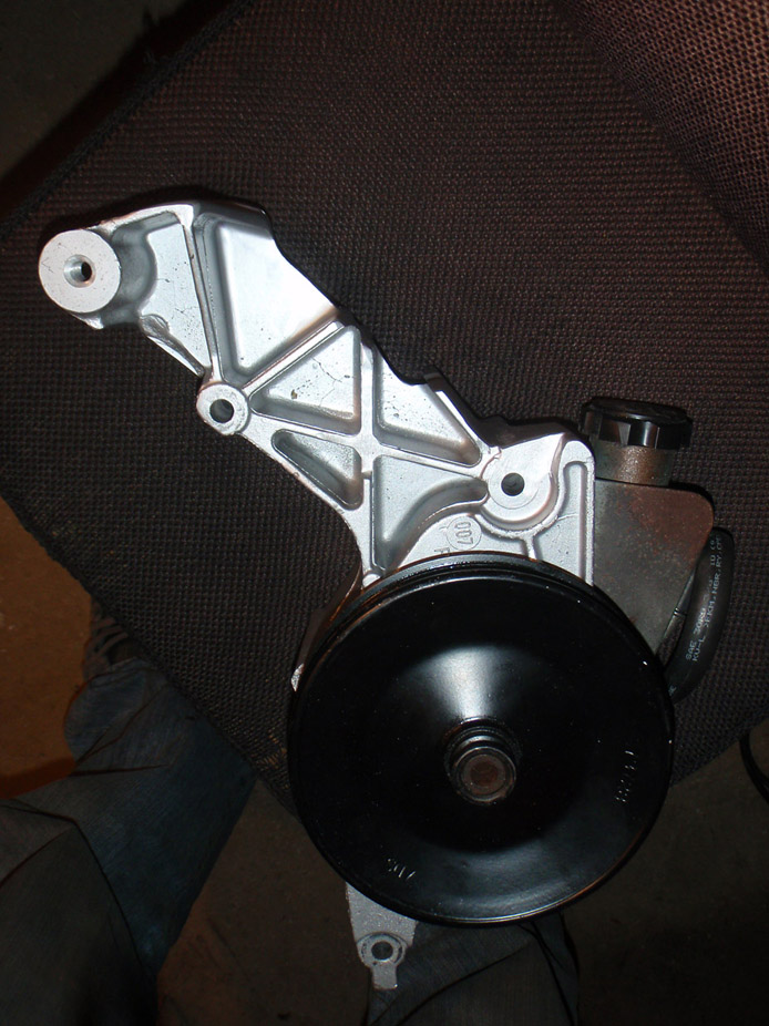
The reason the main relocation bracket is two 1/4" thick pieces and not one 1/2" thick piece is that a) had 1/4" lying around but no half, and b) 1/4" is the exact depth difference between the bracket front bolt face and the inner face of where the alternator bolts to.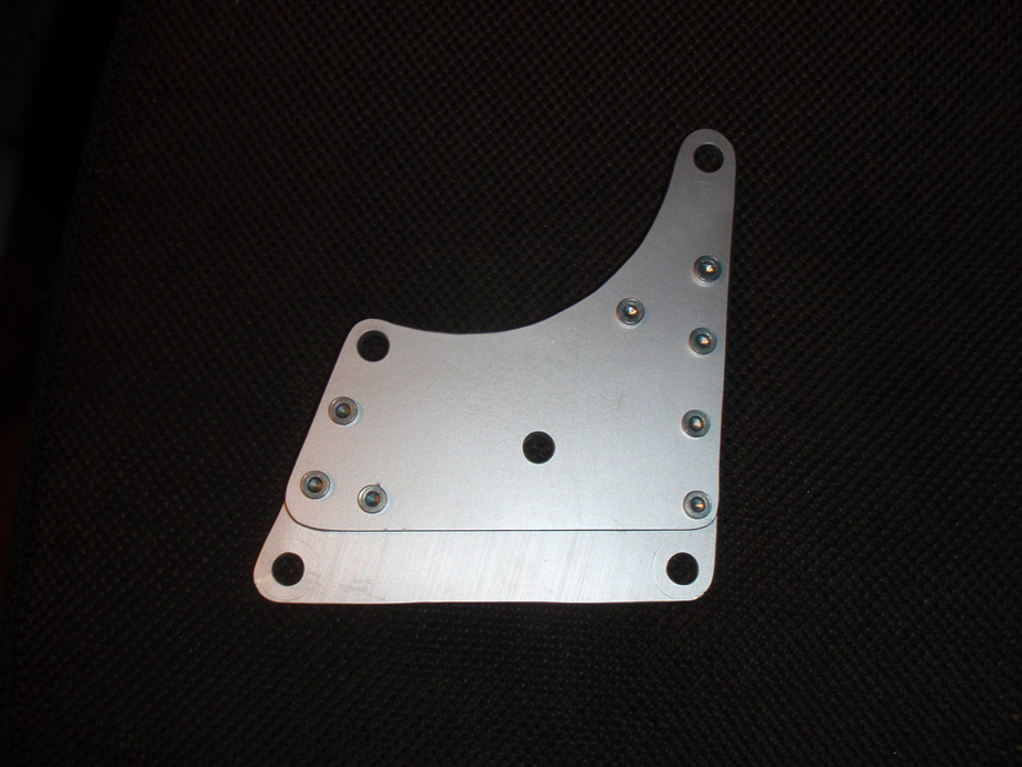
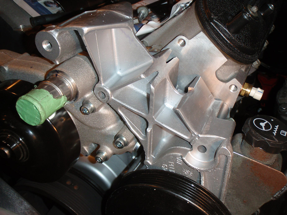
Alternator "back support" plat bolts to the head, and the two alternator bolts as well as the idler pulley all thread into this plate.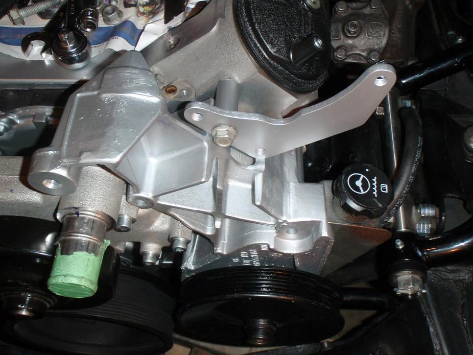
Alternator "front support" bolts thru the stock bracket into the head.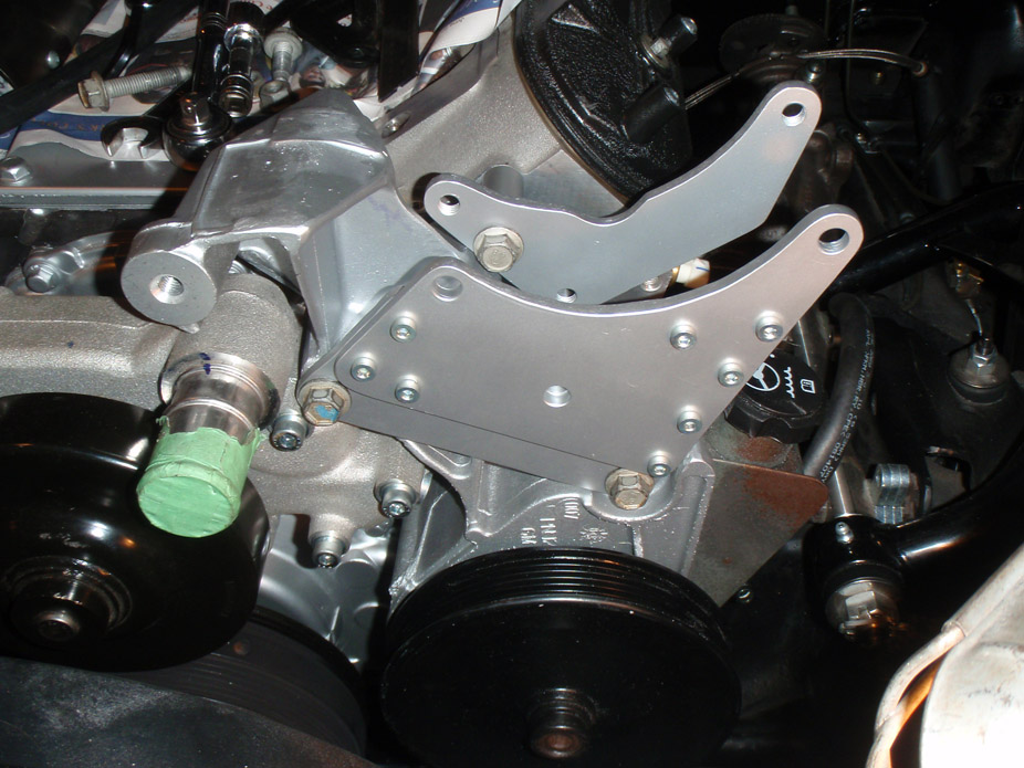
Turned a stepped standoff spacer for the stock LQ4 idler pulley.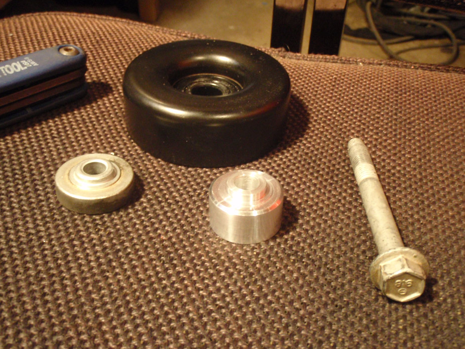
Idler bolts thru the front plate, has a spacer between the two plates, and threads into the rear plate.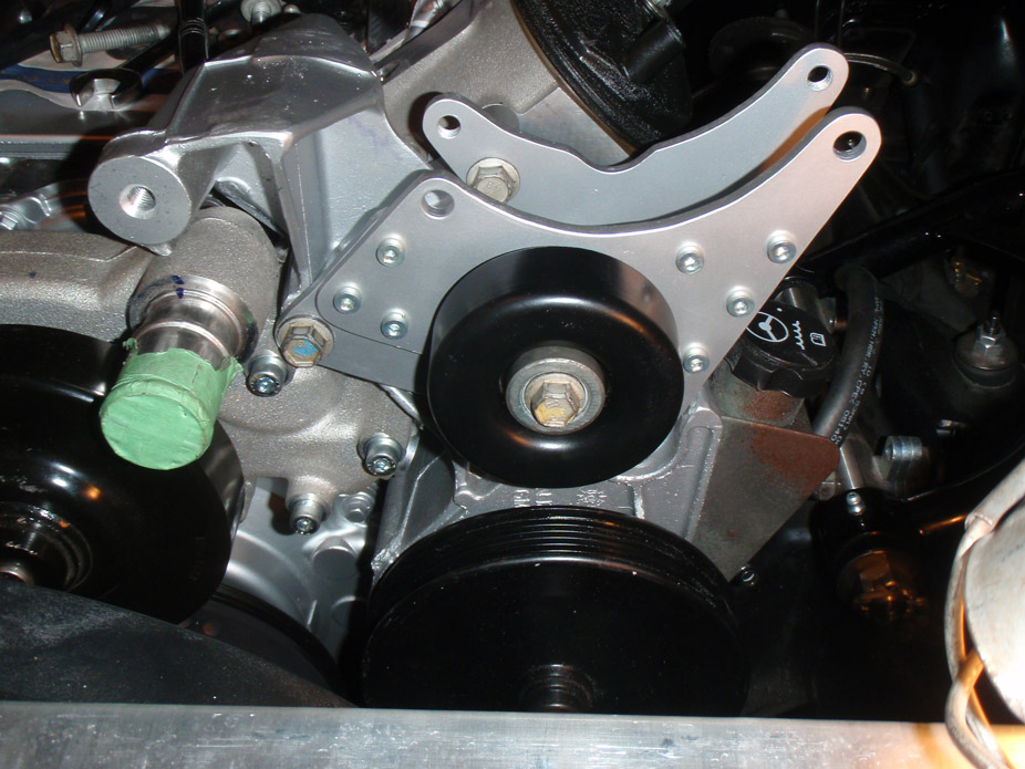
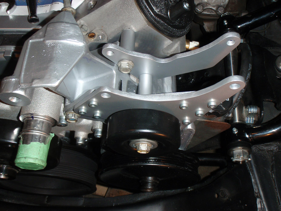
Had to make a tiny notch to get alternator to clear the valve cover.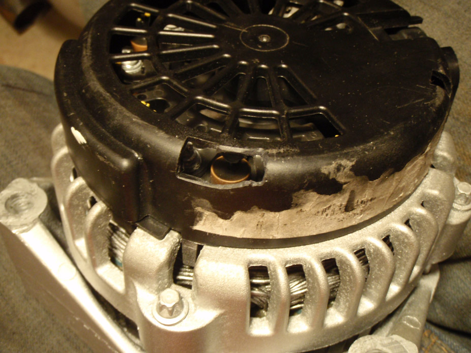
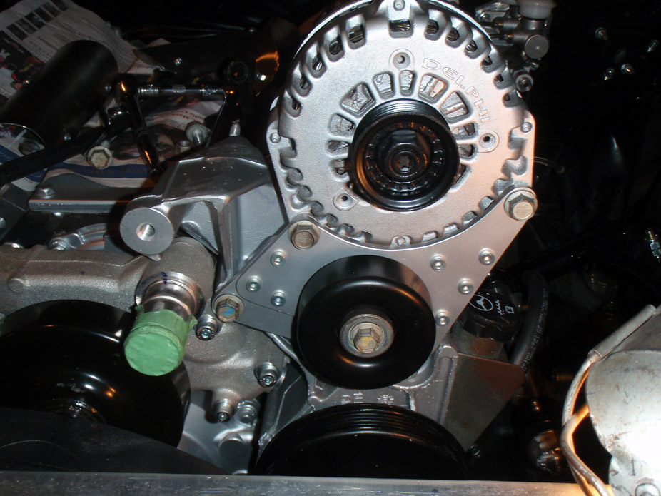
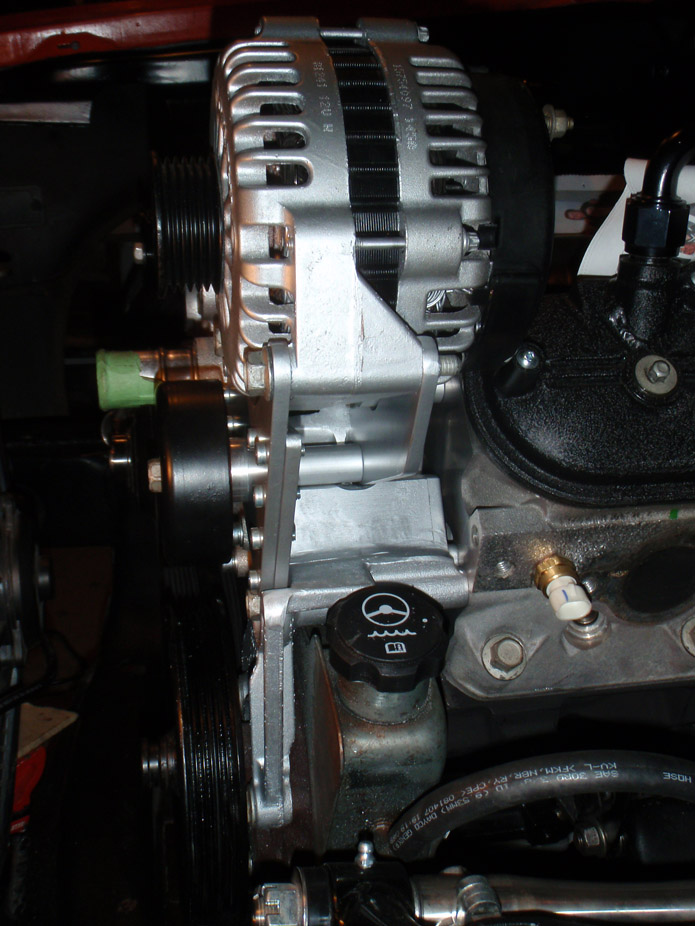
Made a small-diameter pulley to lower the belt to clear the intake tube/throttle body. Has two stacked high-rpm bearings in it.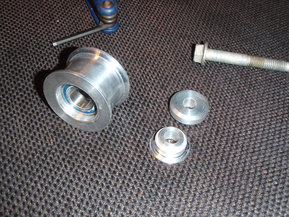
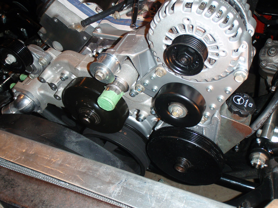
Not the final belt wrap path but did it like this so I could hang that steel rod in it to tension it... everything fits & lines up like a glove!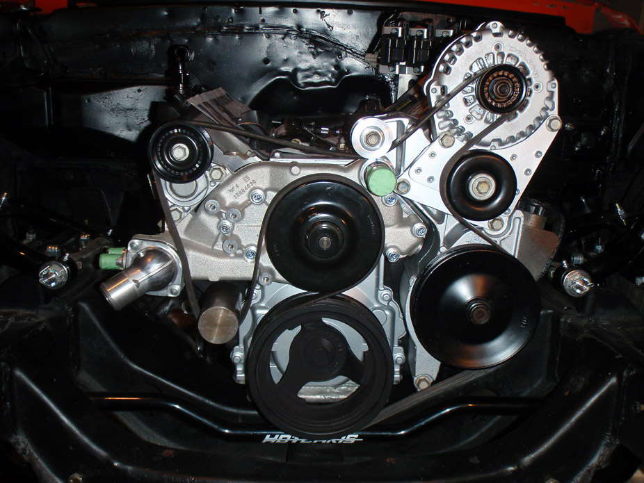
Christmas in July! HOPING this is the last big batch of parts I need to get before it's on the road. Whoever said that these swaps will nickel-and-dime you to death is a lying *******... more like 20'd and 50'd to death haha.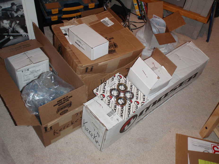
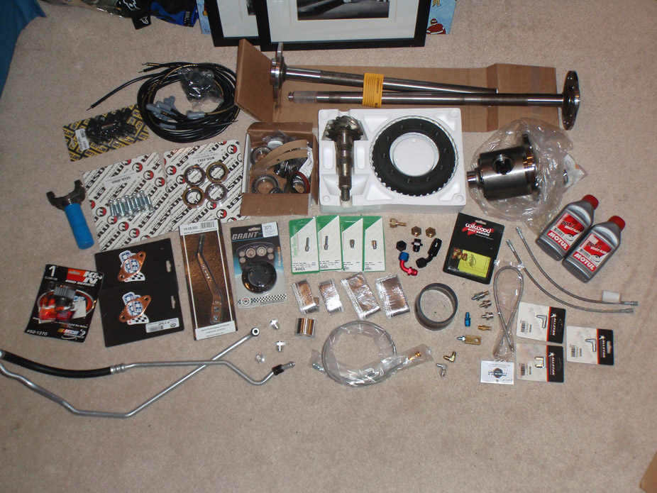
FAR too many hours into this, doesn't look like all that much hah... need about 6" more of weld then they're off to the ceramic coater, will get more argon tomorrow morn. Going to be a big weekend... holy crap.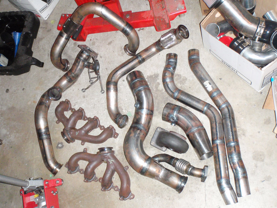
7-21-2011
Finished up the O2 bungs on the hotside piping and dropped that all off to be ceramic coated ($$$!!!), should hopefully get it back by Friday and re-assembly on the engine this weekend
Have a handful of things that I'm juggling at once but things are starting to really come together, and so I'll just update with this little guy I made: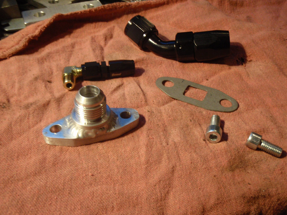
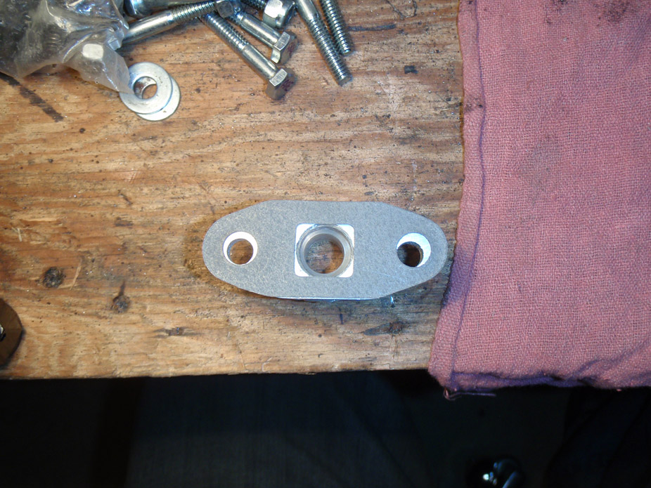
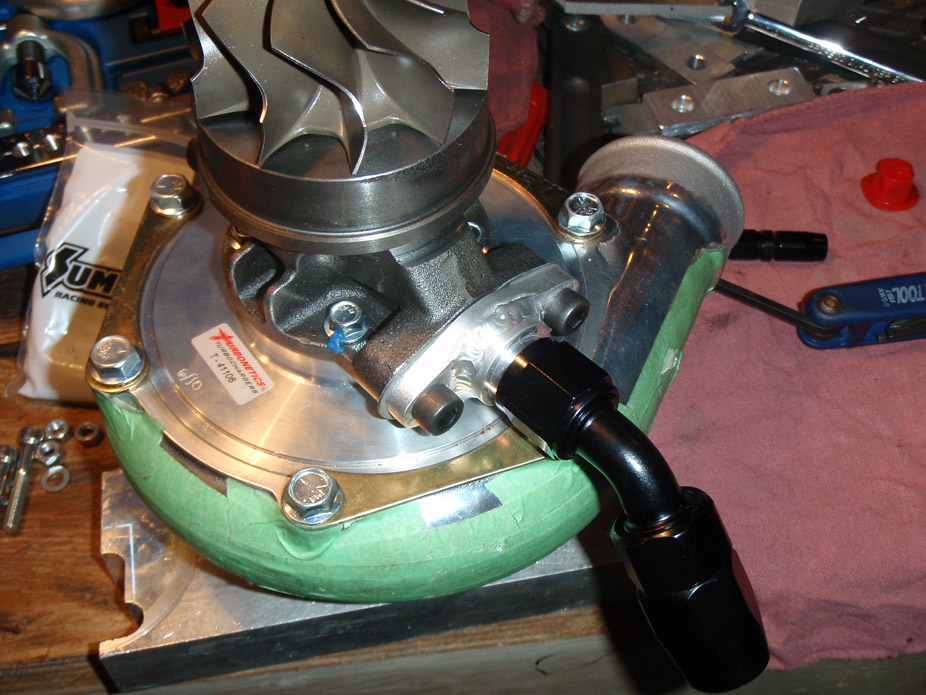
7-22-2011
I'm generally not a sucker for blingy/chromey/shiny things but this badboy looks f&#^$*% badass...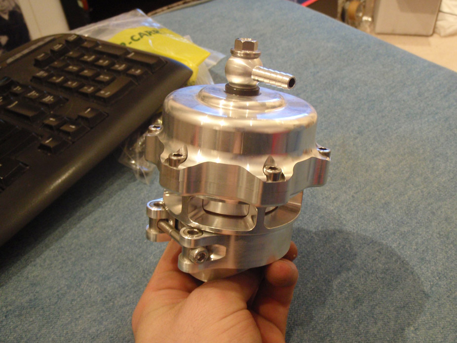
And somehow the stock LQ4 belt fits my custom accessory drive perfectly, even puts the idler in between the two "good tension zone" lines.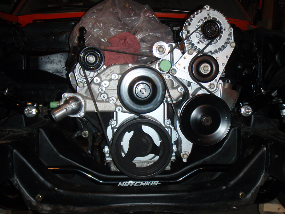
Should have a big update tomorrow, can't wait.
7-23-2011
Took the wastegate to a Scotchbrite wheel to make it look a little less very-used:
7-24-2011
Some stainless heat shields for protection in areas near aluminum or plastic...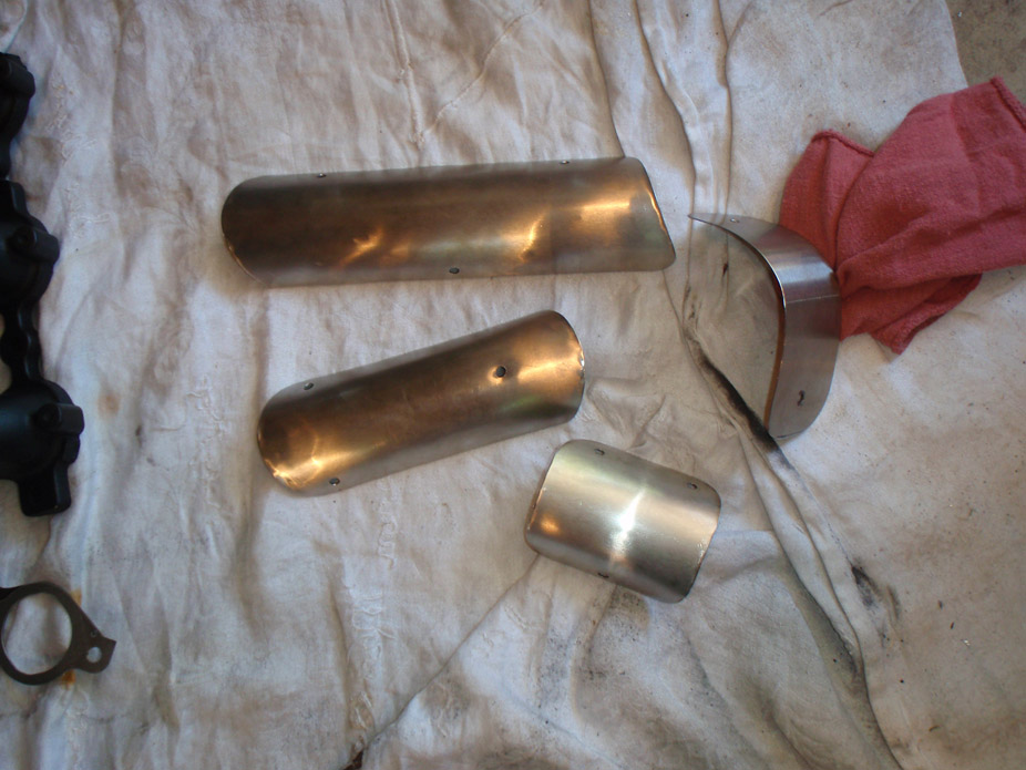
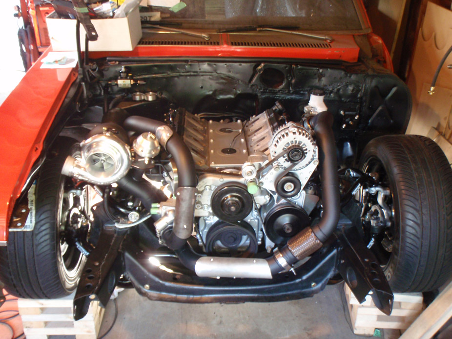
7-28-2011
Heavily modified core support painted and back in car for good: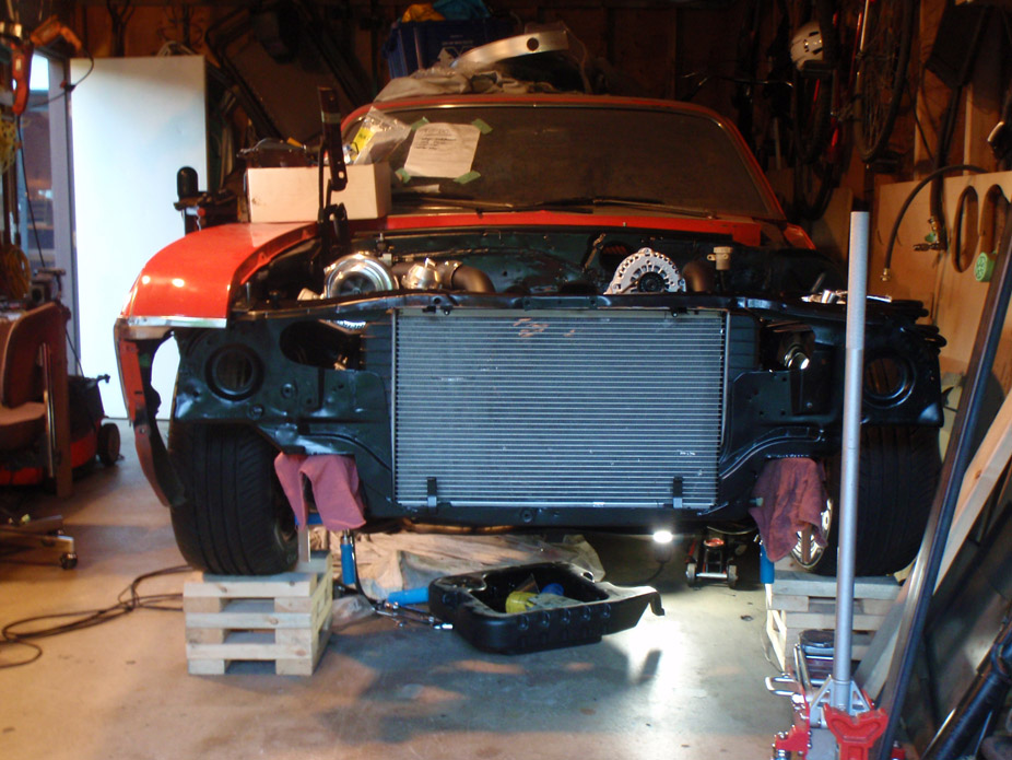
Turned a radiator hose coupler for the upper rad hose: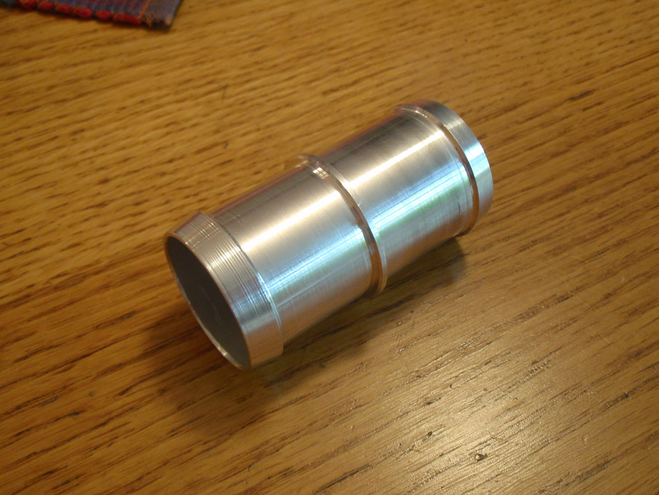
Clean looking: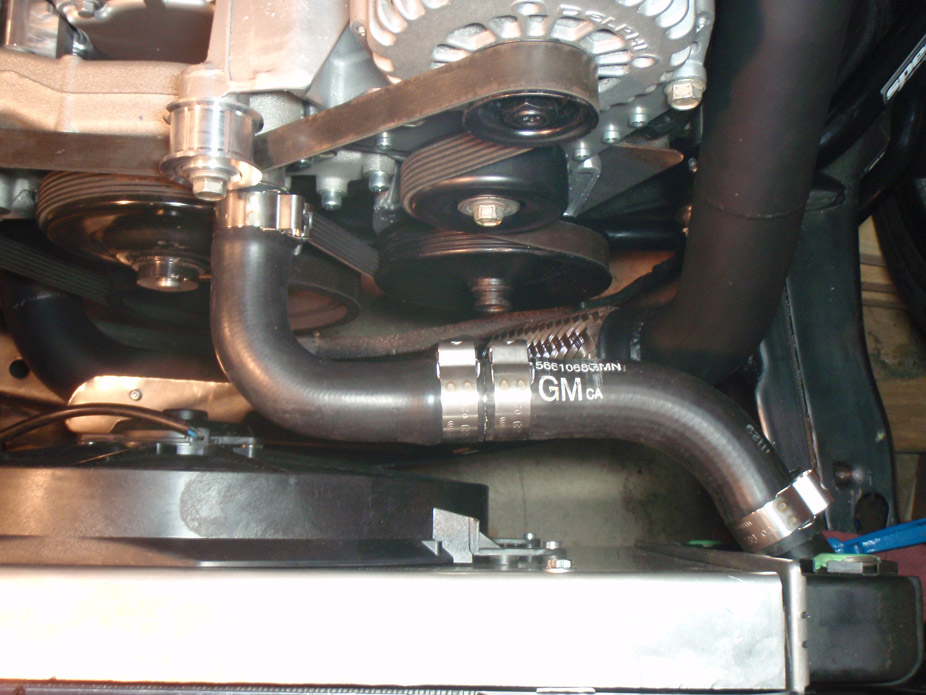
Same story for lower rad hose, bit of heat wrap tape for where it's near the hotside piping: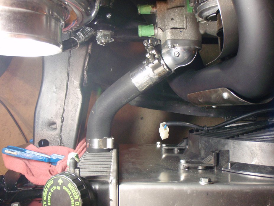
Oil cooler line(s). Have I mentioned how much I love trying to re-use/re-purpose OEM stuff? Dirt cheap from the parts store and this 1 cooler line has 2 steel fittings and pre-flared ends, and still cost less than 1 stupid (blue and red!!!) Aeroquip fitting: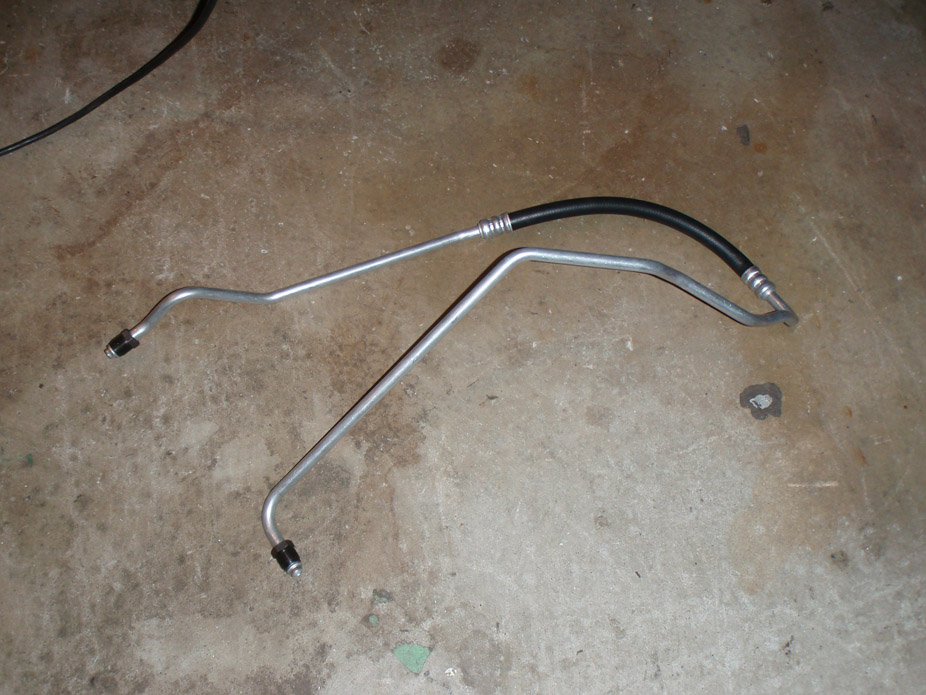
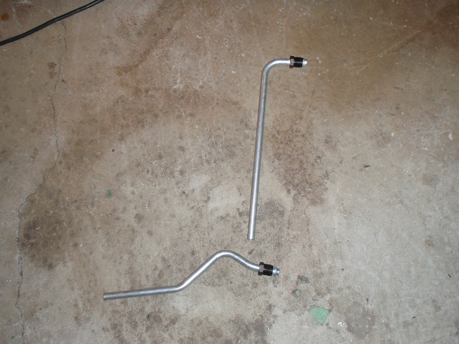
Fits near-perfectly right off the bat, now just needs a couple tweaks and weld some -8 AN bungs on the ends: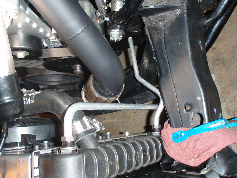
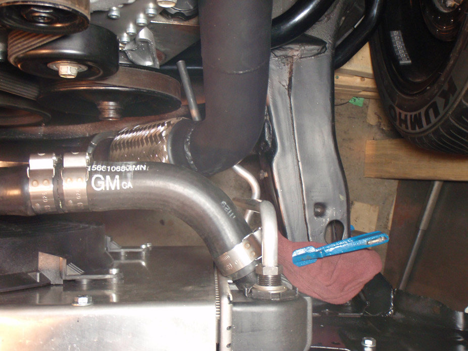
Looking a bit more legit now: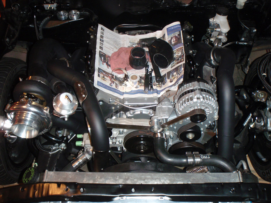
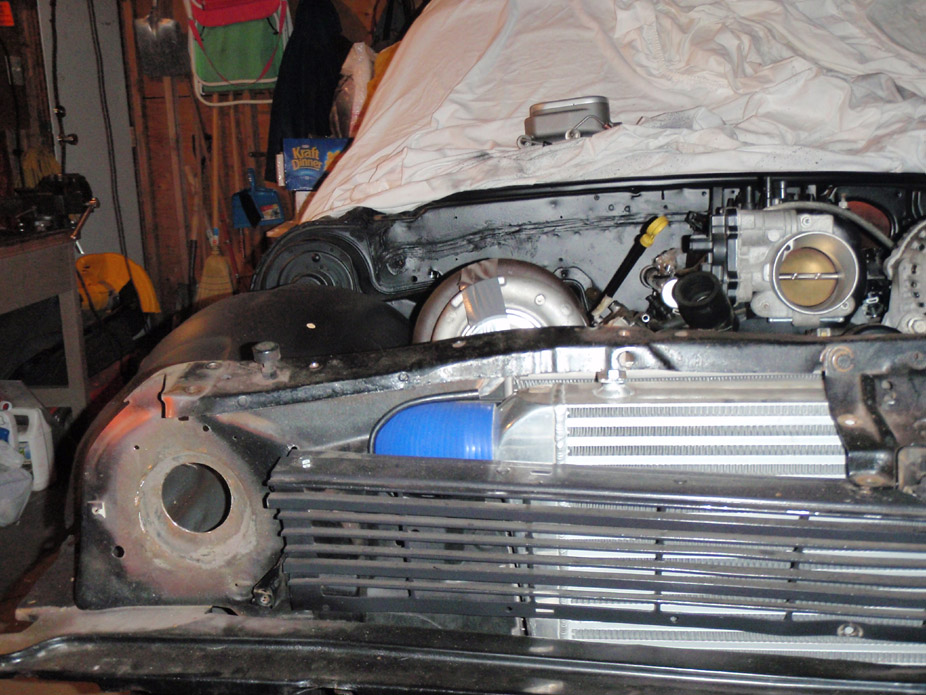
Intercooler looking a bit obvious: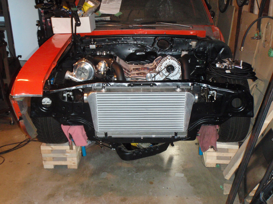
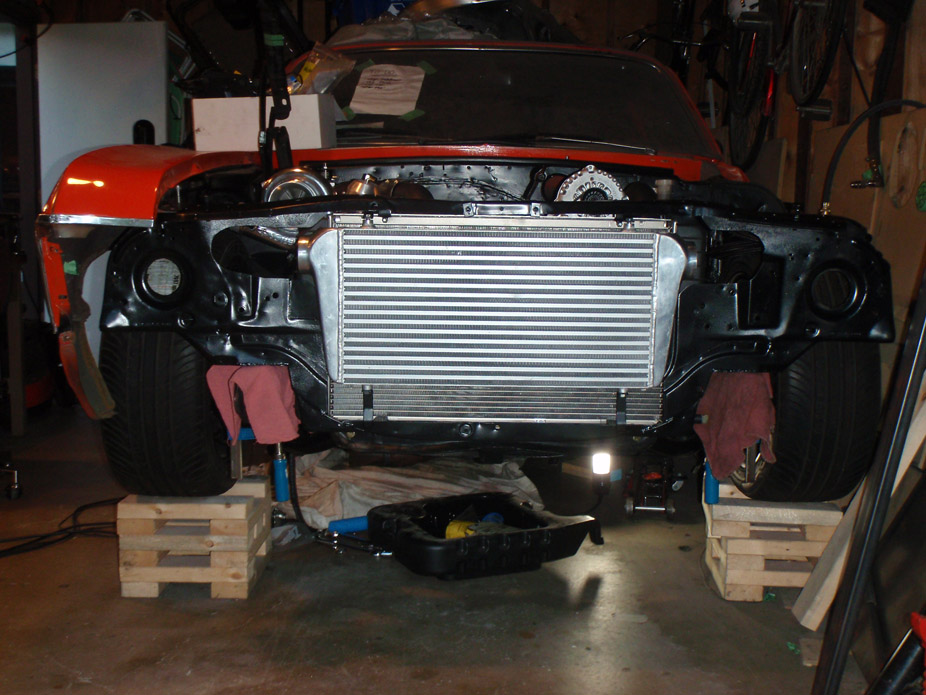
Grill didn't really helps so much, maybe I'm gonna have to give it a quickie flat black spraybomb paint job: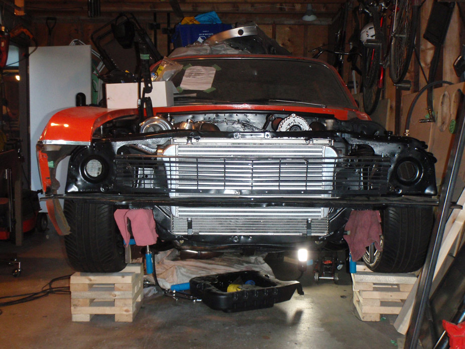
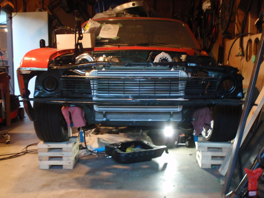
The tire stands are screwed together, but are two seperate "stacks" on top of each other, each stack being screwed together, the bottom stack being 6" tall overall and the top stack being 3" tall overall. The top stack has an additional single 2x4 tie screwed into the bottom of it to prevent it from sliding forward/back, but only side to side (check pic below):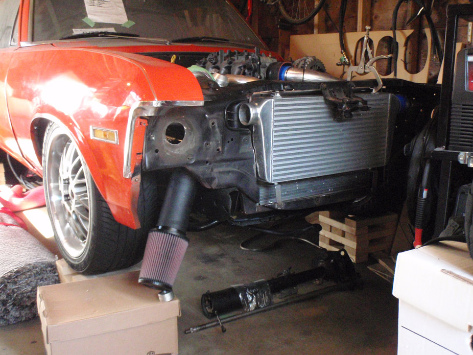
There is a bit of wiggle room though with this setup as you pointed out, from having turned the tiresso many times when checking clearance and setting up my steering linkage.
And yes, things seem to finally be coming together at a decent pace!
7-29-2011
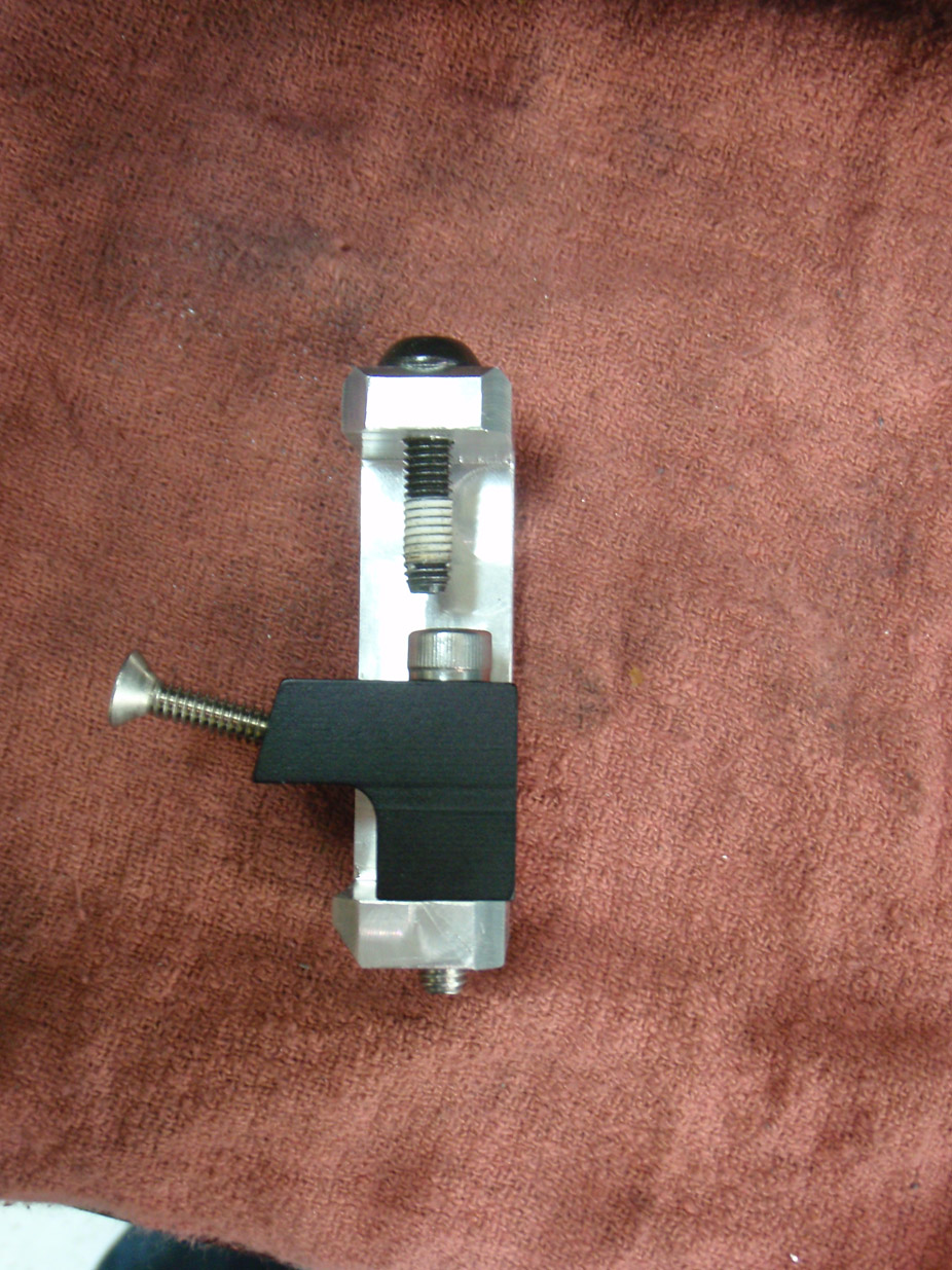
Made some aluminum brackets to hold down the Summit LS1 fuel rails onto the stock truck intake.
LS1 rail mounts that came with the Summit rails: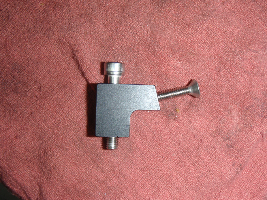
Mockup. They almost worked, but not quite, and were also way too low: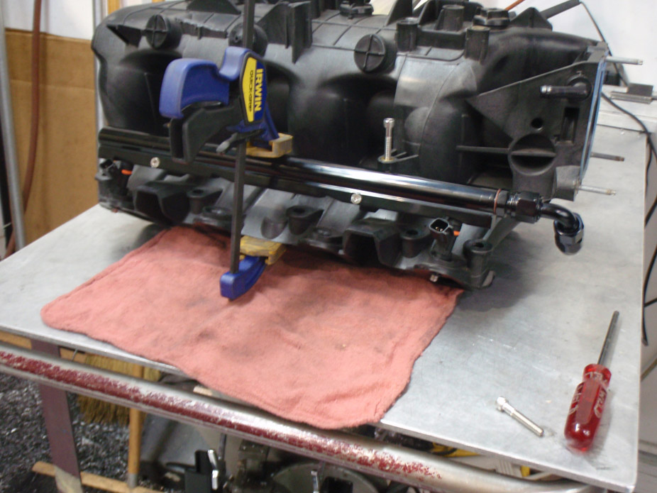
Front: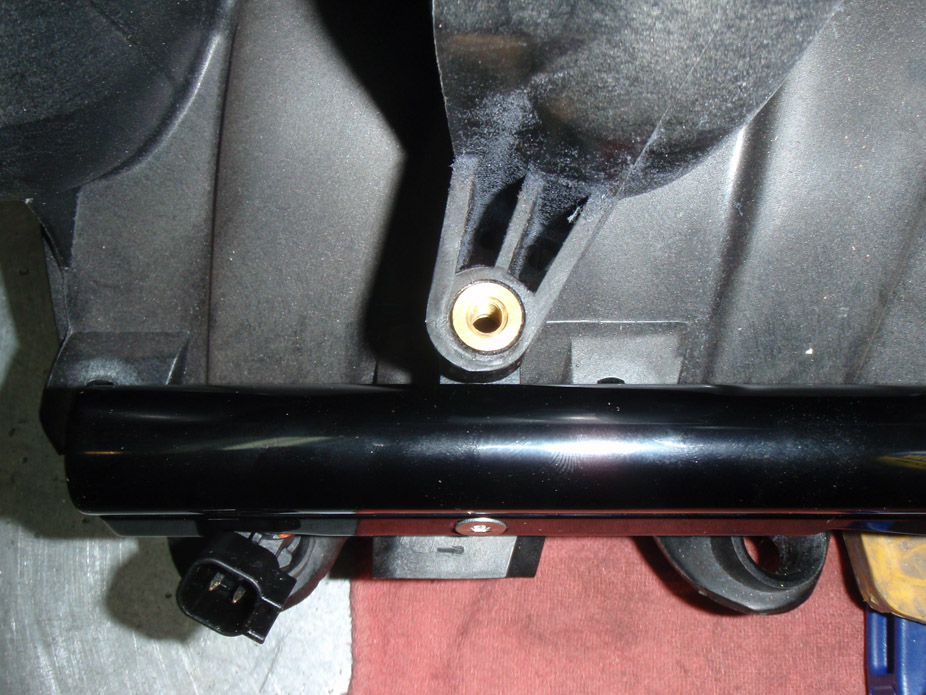
Rear: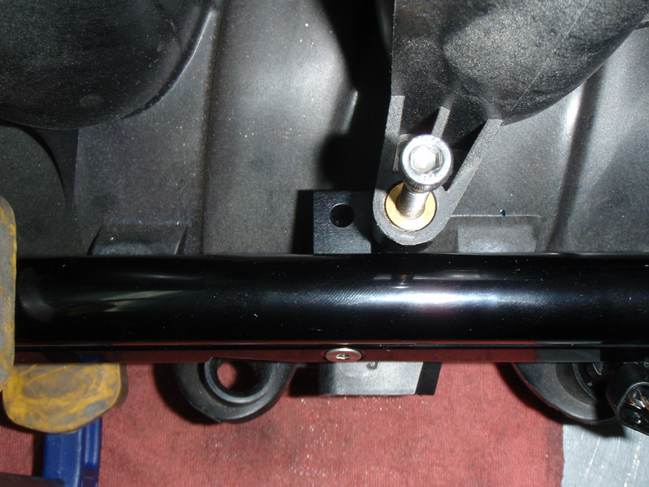
C-bracket adapter!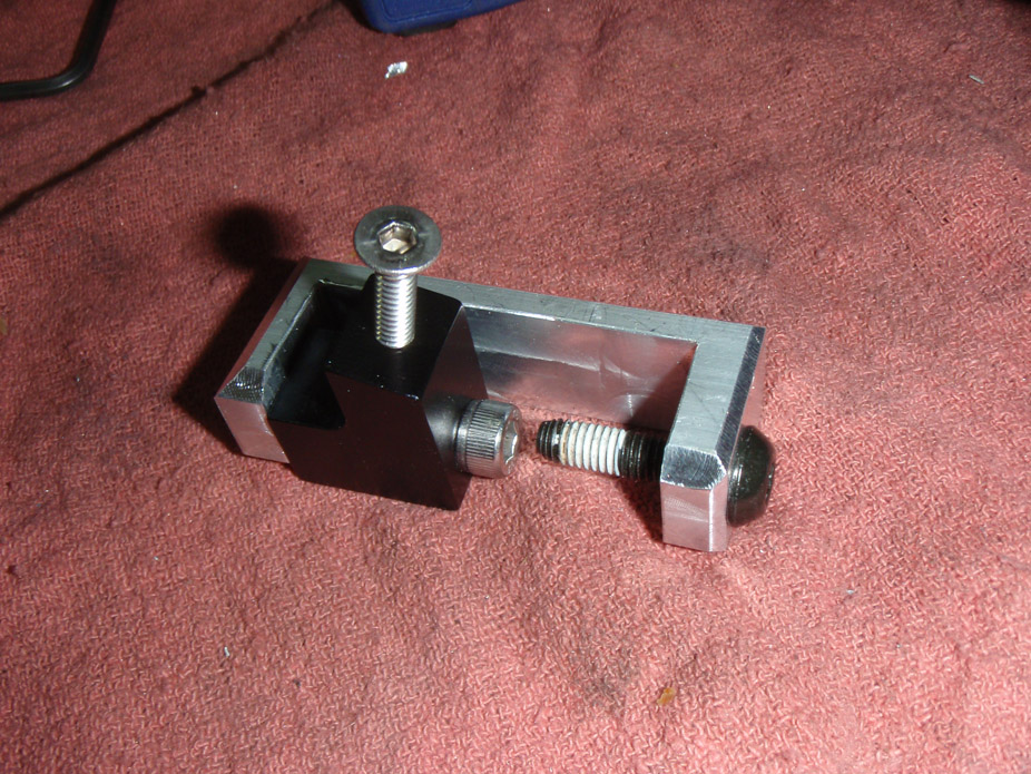
Also made a MAP sensor tie-down bracket. In the truck intake the sensor is just a clip-in and is wobbly as f***... not sure I liked that for under boost.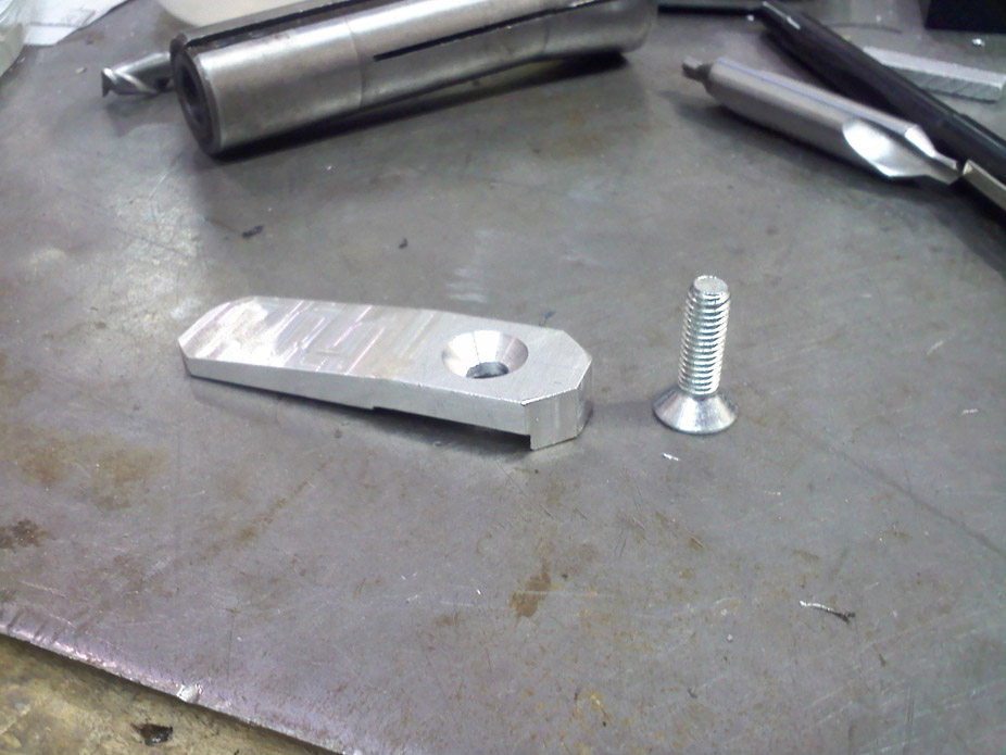
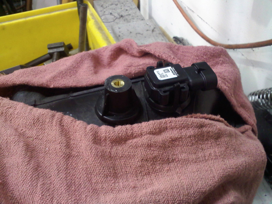
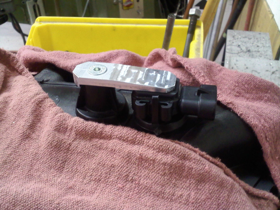
Time to clean up this tab business on the truck manifold: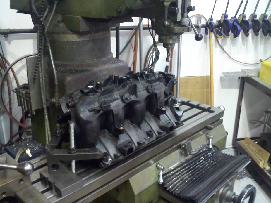
Looking a little better: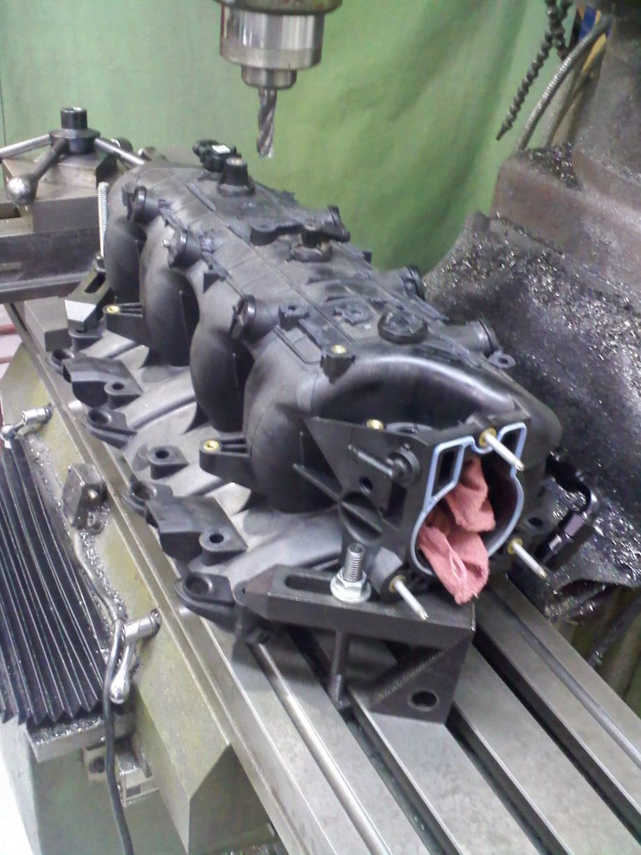
Why is "Semi-gloss black" only barely barely less glossy than gloss black?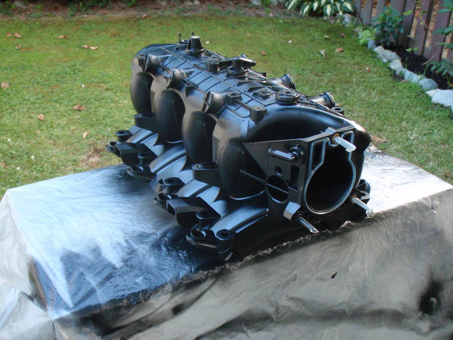
Looks slightly less-bad than a pure stock one, but it's still no FAST LSx intake: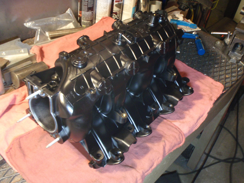
Brackets blacked out, of course: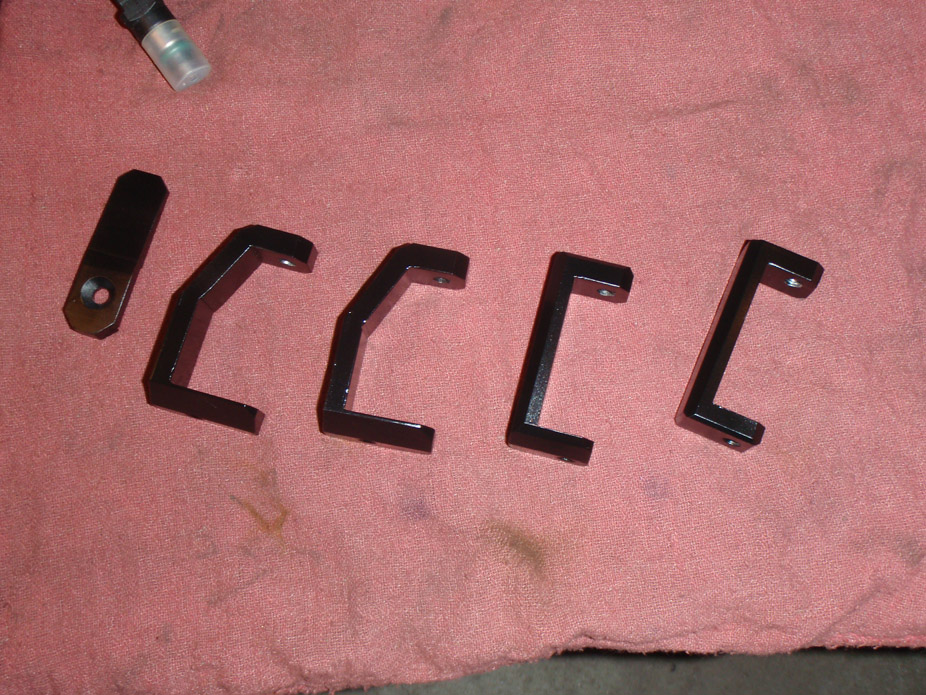
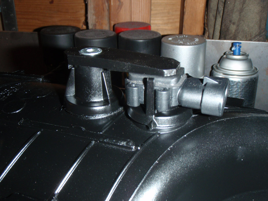
Brackets on: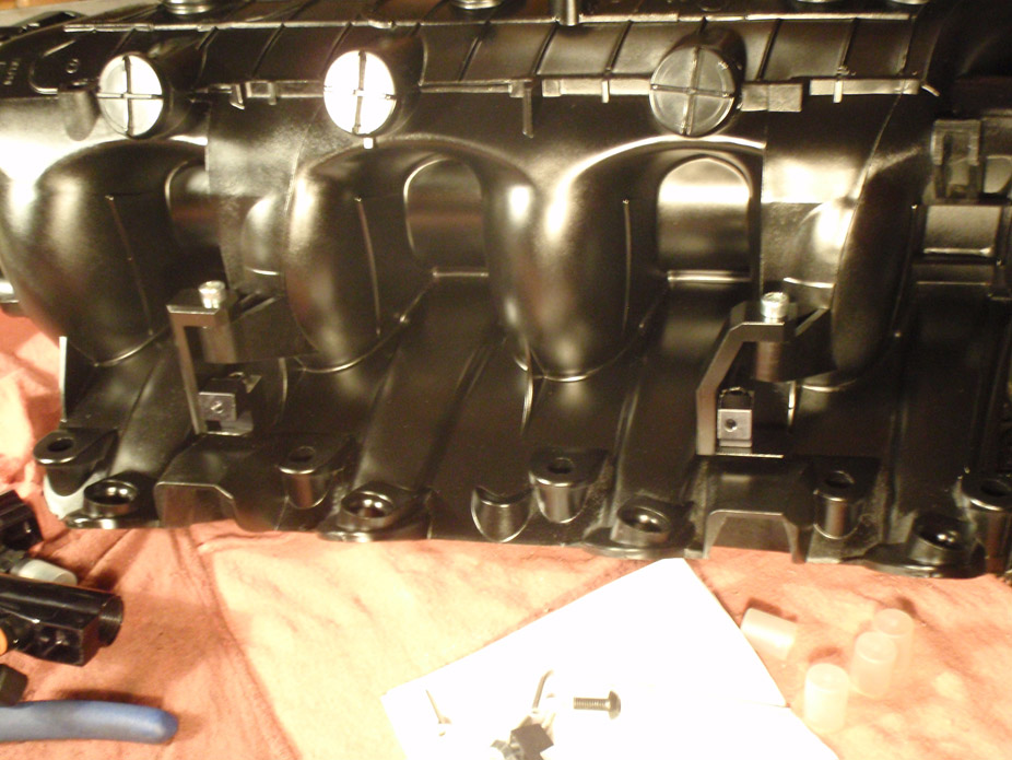
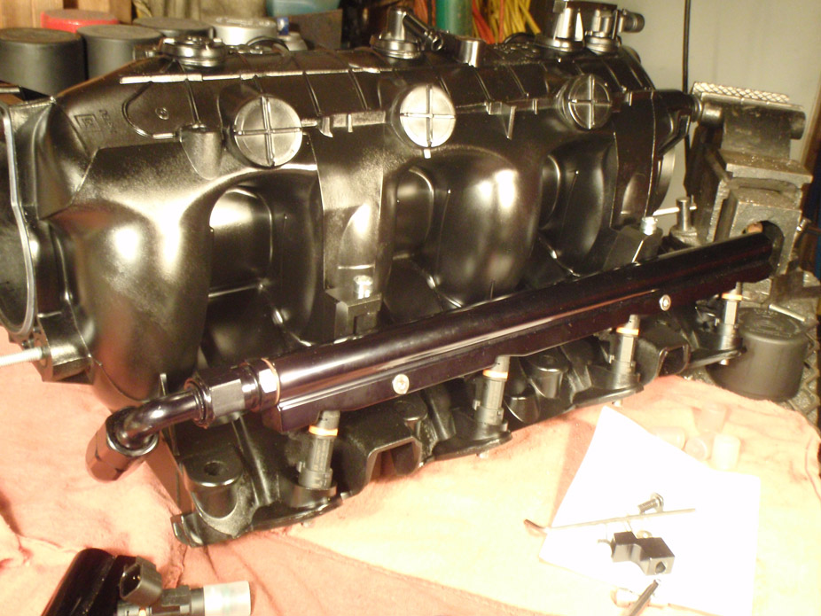
I'll settle for this: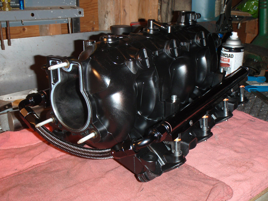
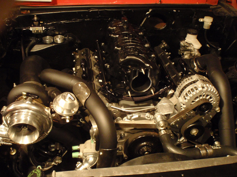
Finished up modding the intercooler and gave it a very quickie spray job. Barely dusted the fins with black, went and looked up close with flashlight and the paint didn't even make its way into the fins, only caught the front edges... I doubt it'll reduce heat-dissipation capacity, and backside of intercooleris still raw: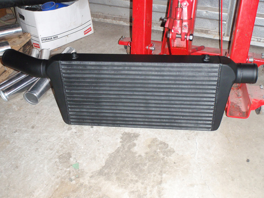
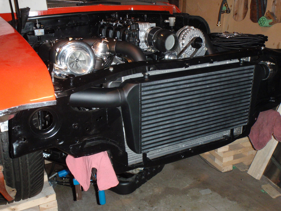
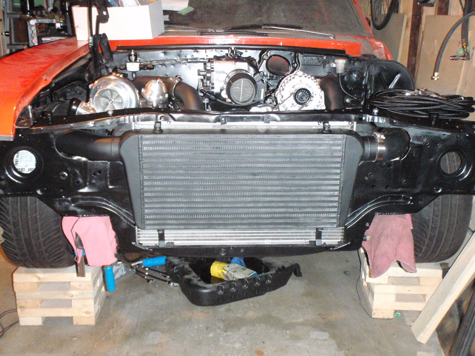
7-31-2011
Remade the coil relocation brackets to make them less flexy and to also have the passenger side one have a clearance cut for the heater hose: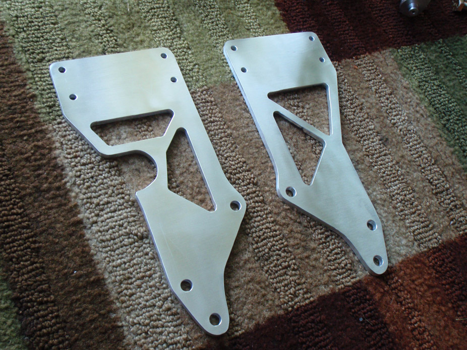
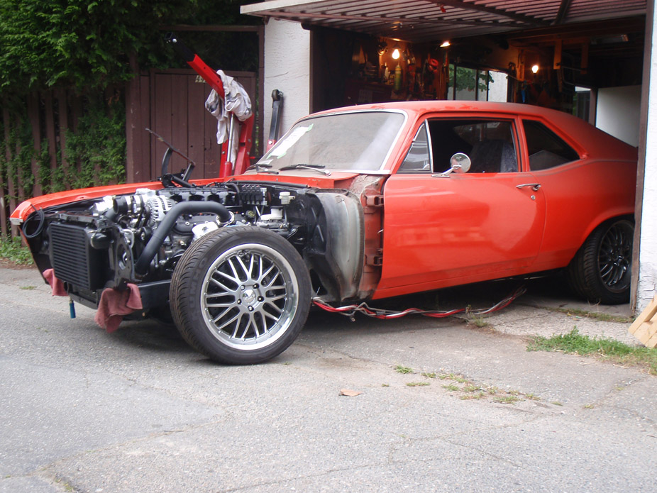
Warning, the rest of the post is completely useless, just has glory shots of the first time the car has seen outside in maybe 2 years. Had to turn it around to get easier access to gas tank/diff to work on those. Man seeing it low on the ground and rolling around got me so excited to drive it hopefully soon!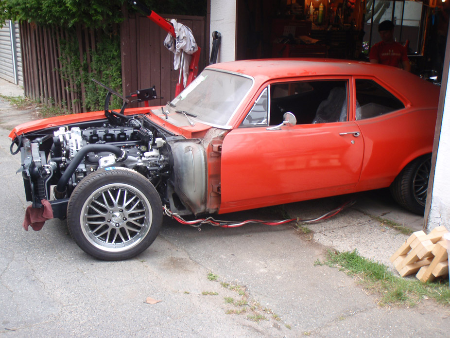
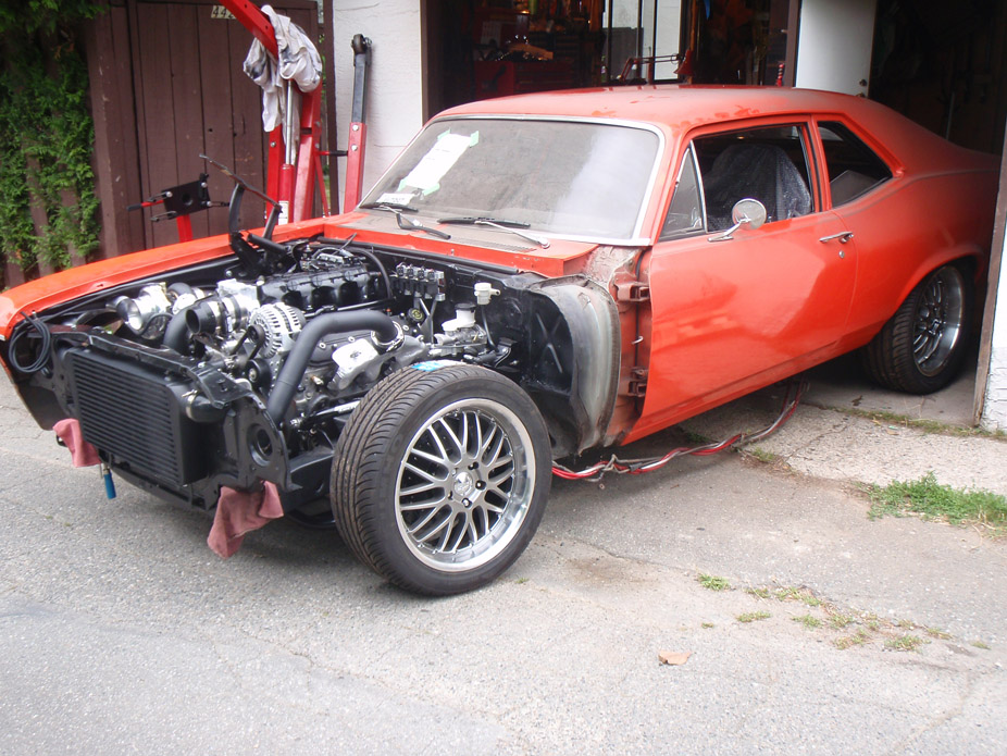
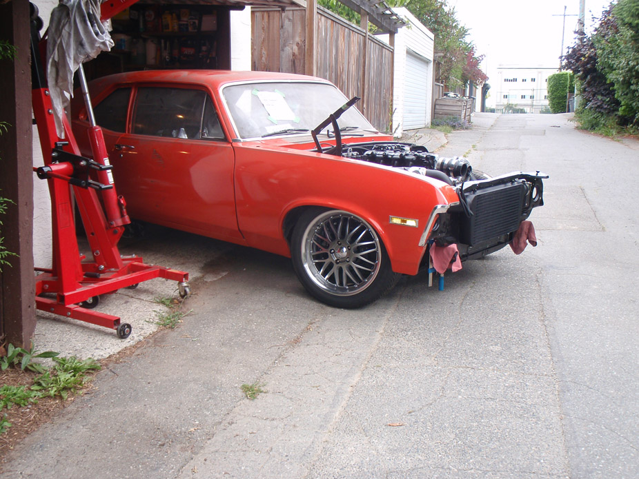
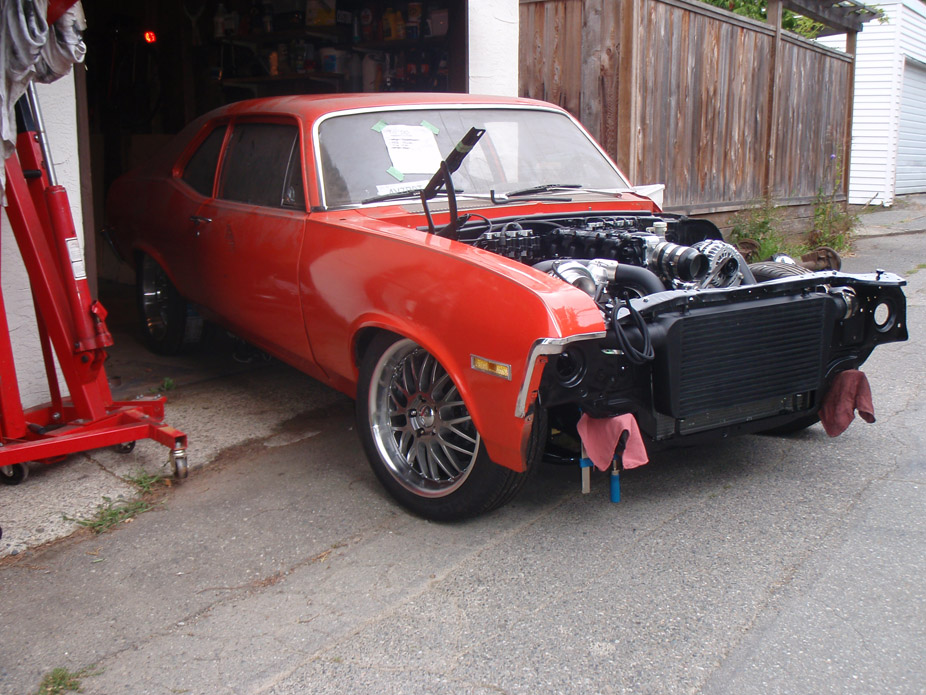
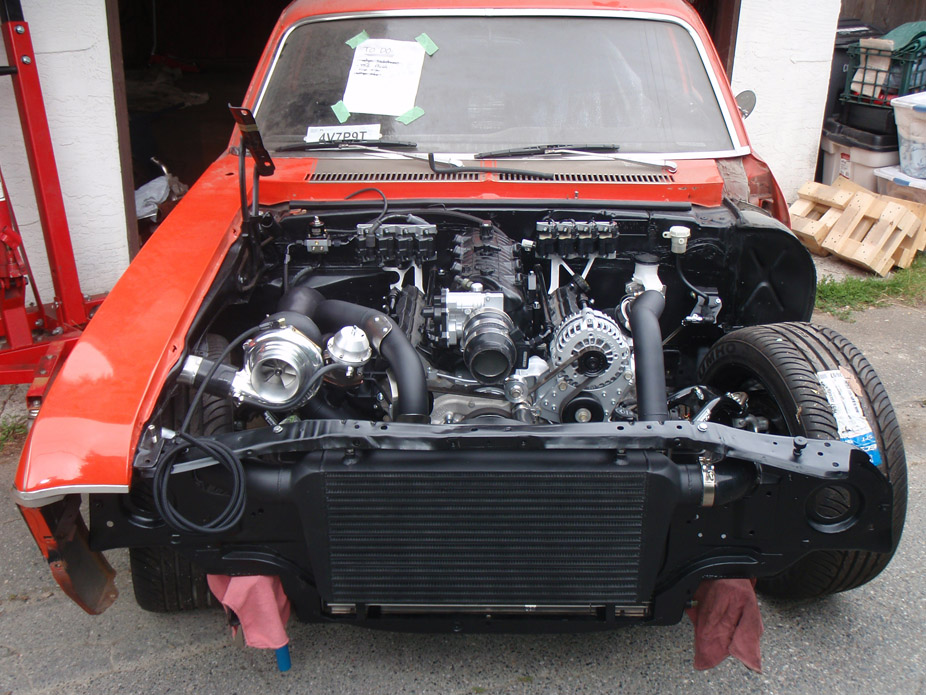
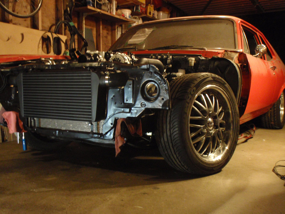
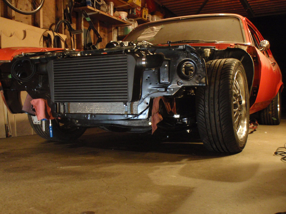
8-14-2011
So I've been juggling a handful of misc stuff to get the car closer, like steering column, seat rails, steering wheel adapter, instrument gauge, will update pics of the gauge panel when I get it 100% finished.
For now have just started the two big projects left: gas tank modding and rear end rebuild: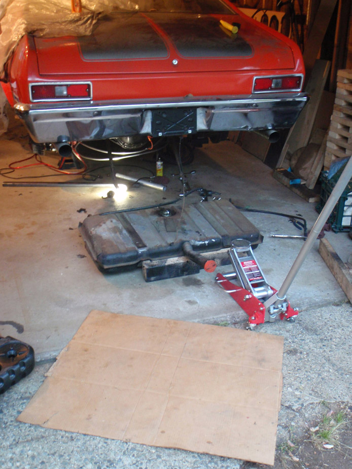
Just got a new gas tank because old one was rusty and gassy, and there was a HUGE dent up into the bottom of the tank right where I want to put a sump/baffle.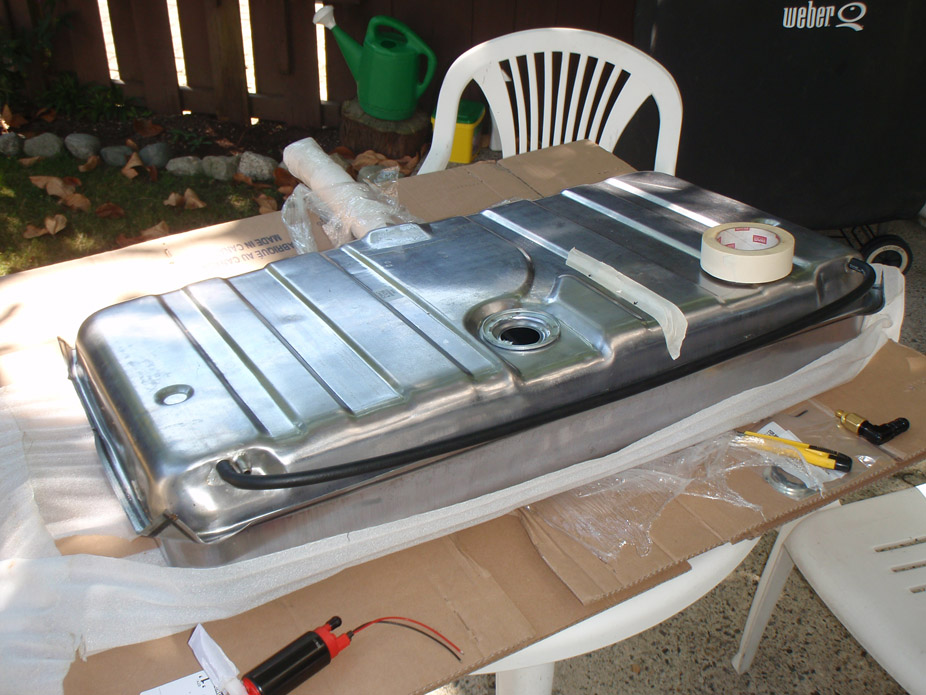
Cleaning this and pulling all the old stuff out sucked a lot: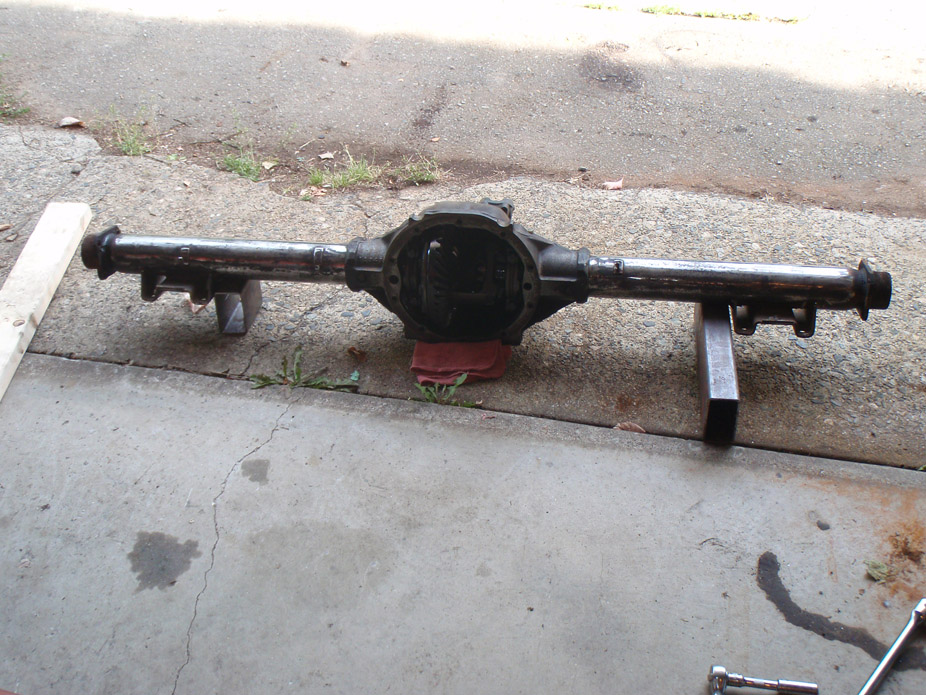
Here are the spark plug wires I made. I reeeeally wanted 90's on the coil packs, but regardless of the company I could only find 45's or straight ends, so I mixed and matched.
Below are the (going counter-clockwise from very bottom) Taylor universal SBC plug wire with 90* (HEI i think) distributor end, Taylor 90* LT1 distributor end (because I read that they have the same terminal as a coilpack, but the rubber boot didn't end up fitting over the coilpack plastic), stock-replacement MSD plug wire for truck coil packs, and MSD 45* end (which I thought I'd have to settle for in order to get a boot to fit over the coil pack):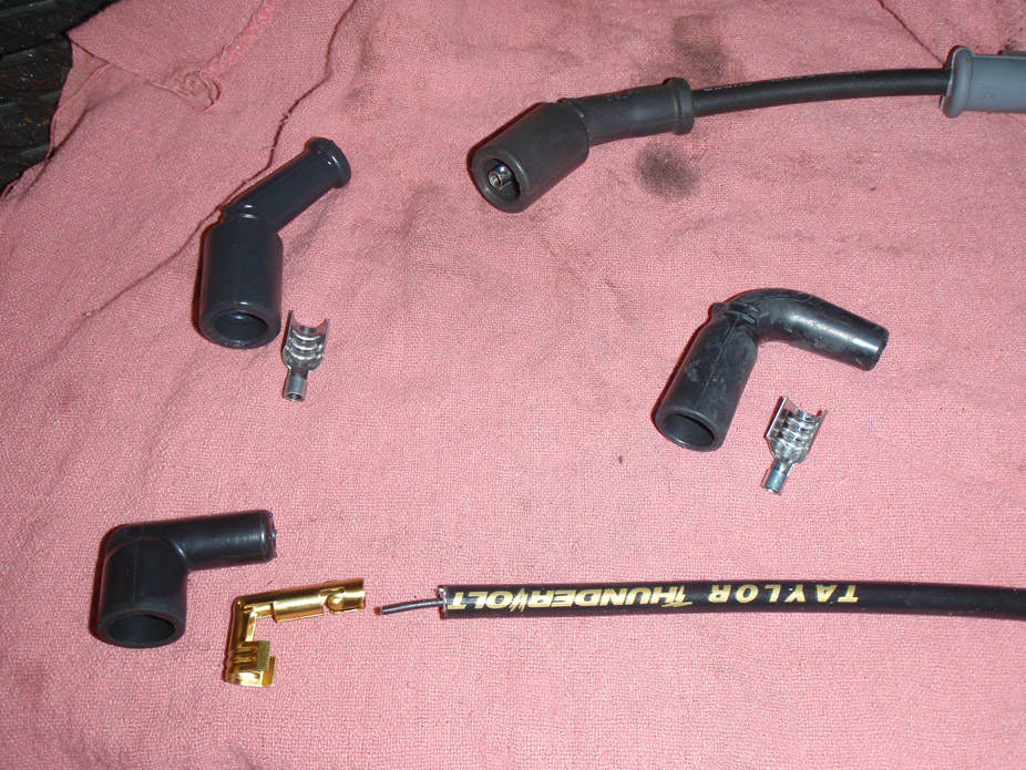
Turns out the extra MSD LSx ends I got were unnecessary, I jammed the HEI boot over the wire and crimped the LS terminal on: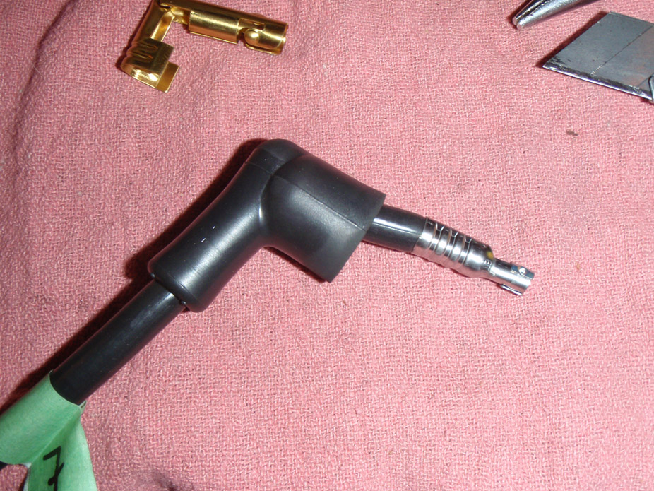
Have to say they fit quite well:
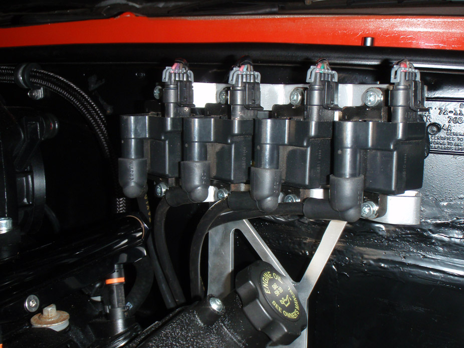
Not fully organized/routed, but great clearance all round from the manifolds: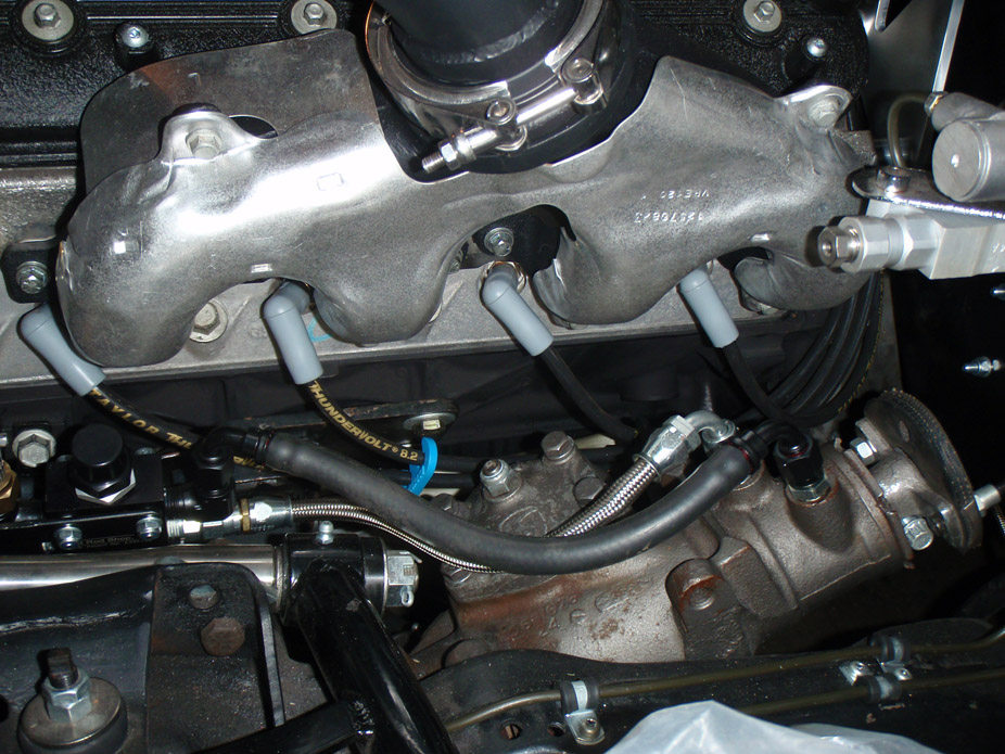
Glad I could get 90's to work like I had orginally envisioned, just looks so much tidier: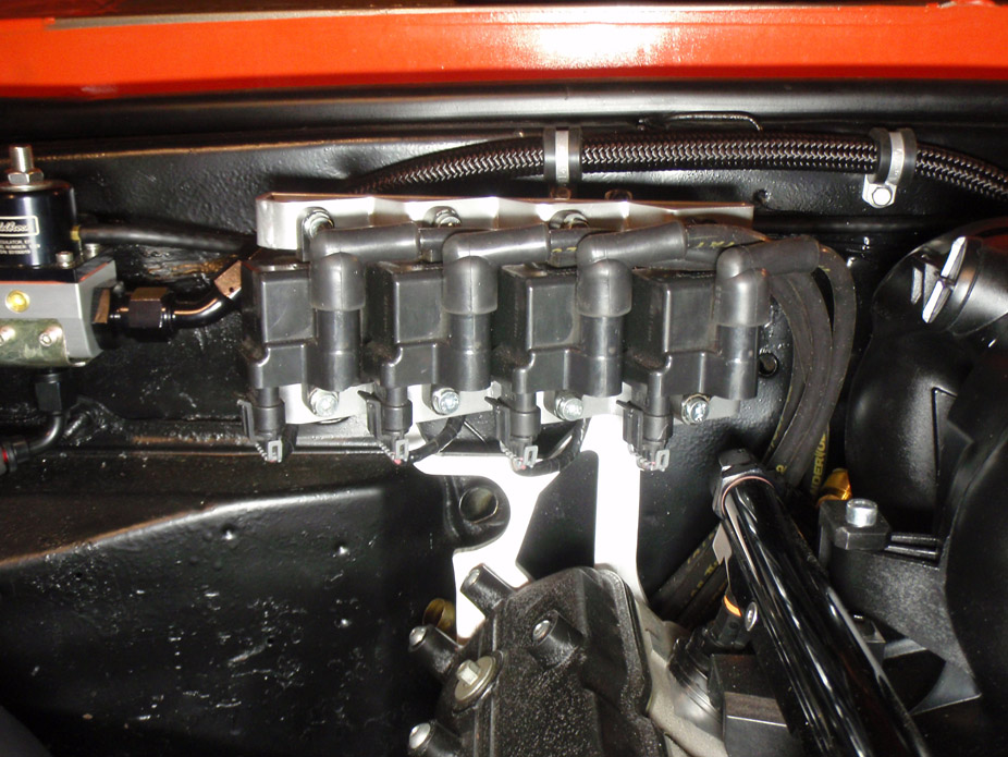
Again not fully organized but shows the nice clearance possible: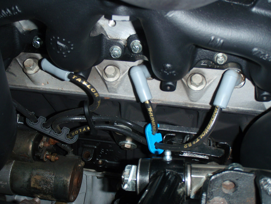
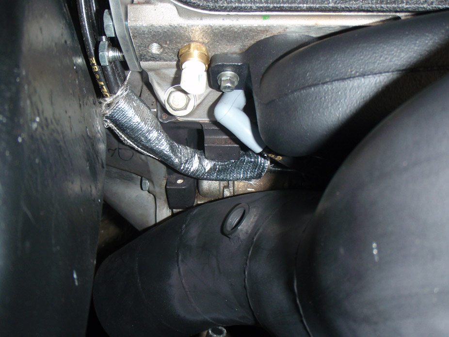
8-16-2011
Disassembling this rear end has been nothing but a pain in the ***, but finally got all the old stuff out of it tonight.
The carrier cross-bolt retaining bolt/pin is notorious for breaking, and it was broken in mine too, and rusted/stuck in there, so since the open carrier is as good as dead to me, a cutoff wheel made short work of freeing the carrier cross pin: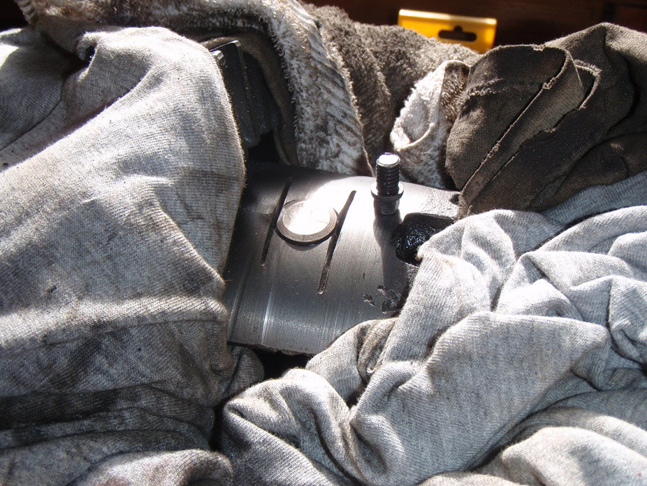
On the weekend sweated a bunch in the sun wirewheeling the outside, then painted it with some Tremclad rust paint, then decided to weld the axle tubes on, so wirewheeled again... oy: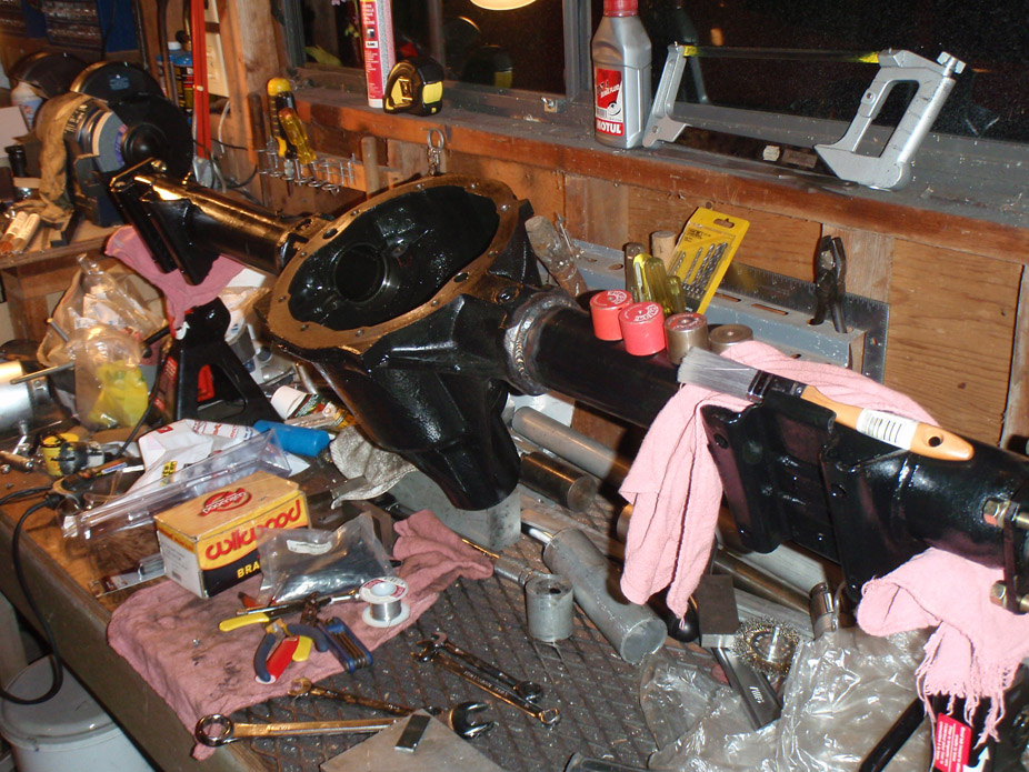
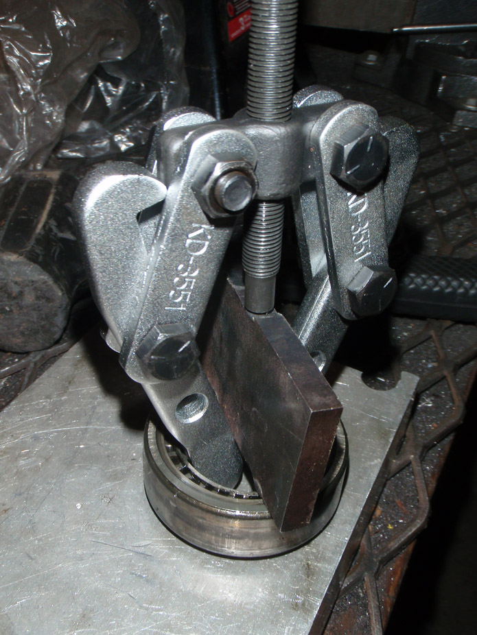
All the other bearings were decent to pull except for these axle bearings, the typical hammer-from-backside maneuver didn't work at all, so had to rig up a puller somehow, glad it worked. Center push pin presses against the steel plate but still has enough clearance to pull the bearing out flush with the axle tube end: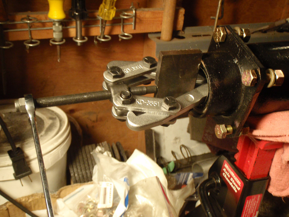
Closer shot, can kindof see a bit of 1/8"x1" flat stock that I wedged between the two puller jaws to prevent them from coming together and slipping off the bearing ID: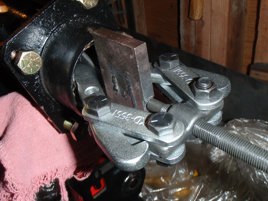
Just as the bearing came flush with the axle tube, the puller would lock itself out against the 1/4" plate I put in there for the center pin to push on. Since it locked out it gave good leverage to just wiggle the bearing out the rest of the way: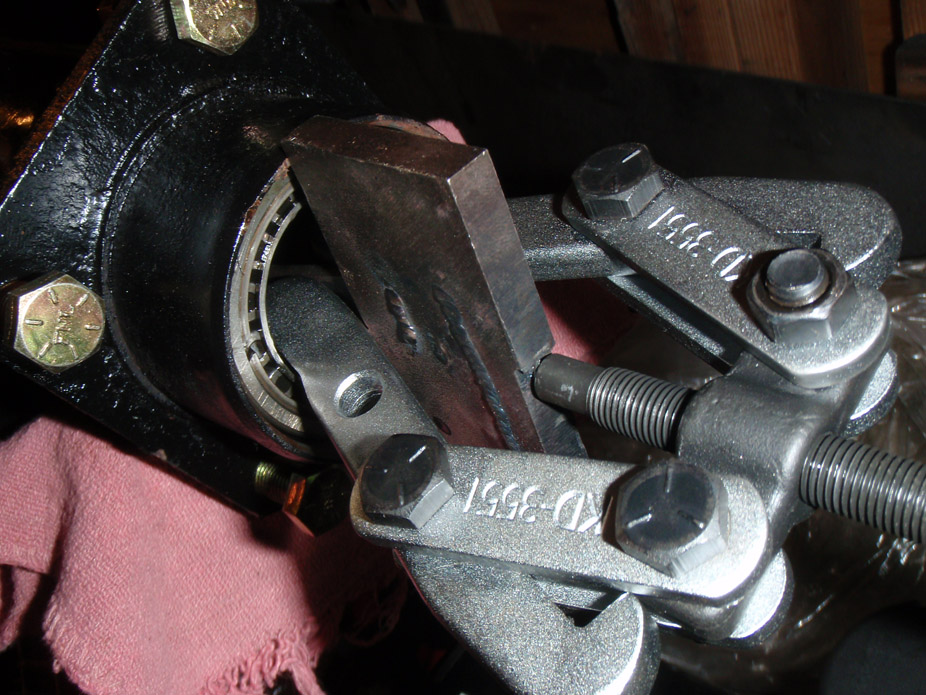
Next task is setting the pinion depth, had to destroy the previous bearing to get the pinion shim, so can't use that bearing for mockup... not looking forward to that part of the rear end build. After that it's backlash and just throwing it back together, with the Wilwoods... excited for it to get to that part.
8-20-2011
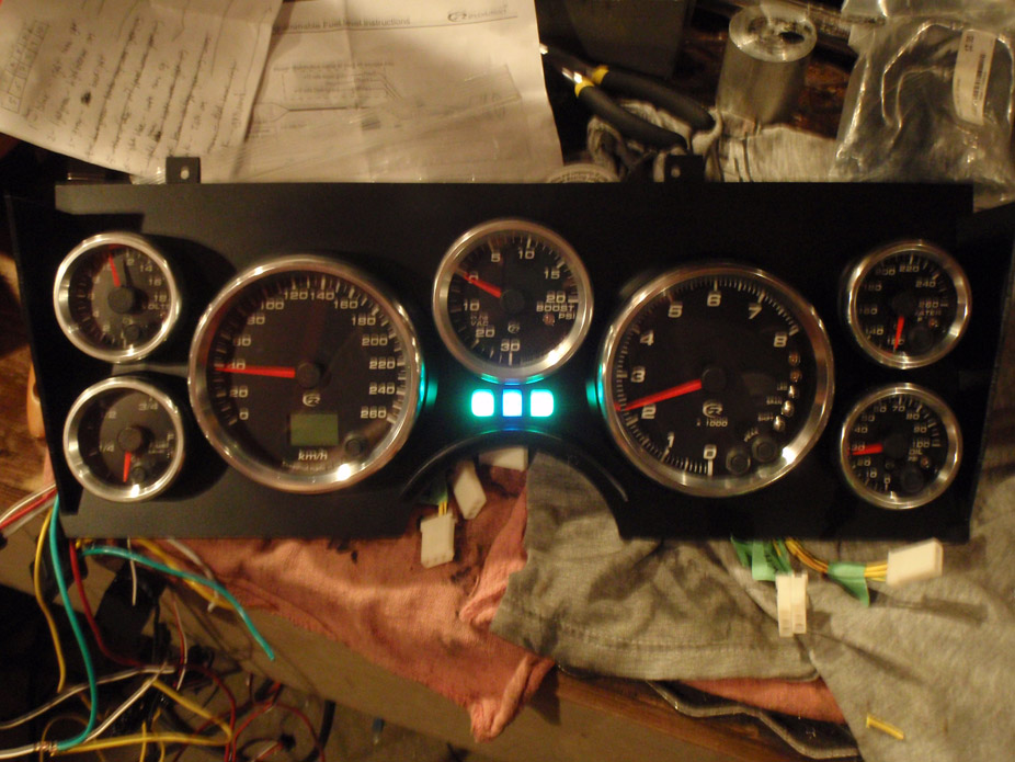
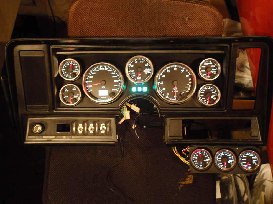
FINALLY wrapped up the gauge cluster... took long enough haha: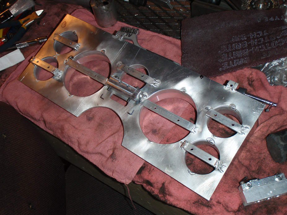
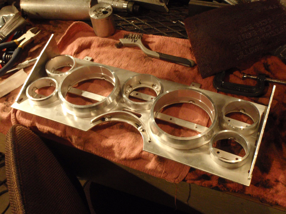
Just spraybombed it semi-gloss black, turned out ok: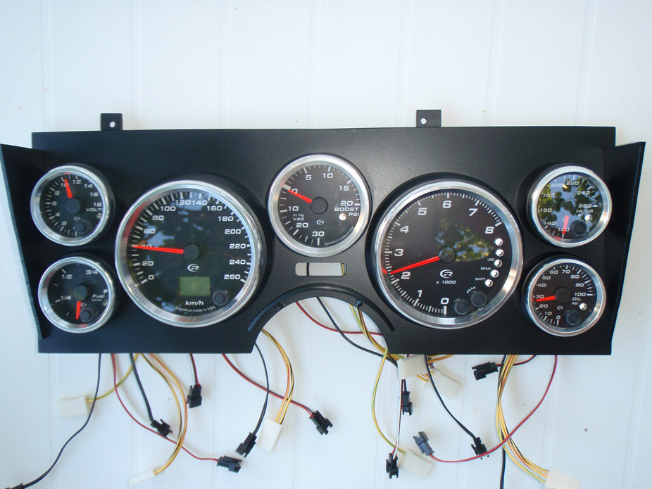
...hole in the panel just below the boost gauge is for this, my secret customized OEM weapon, the stealth turn signals maneuver...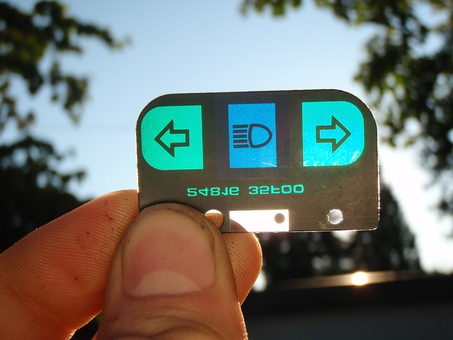
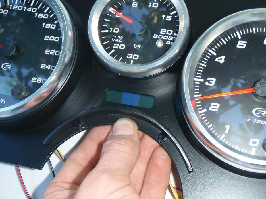
...for which I needed some ghetto lighting situation (getting to the point in the build where stuff is "good enough")...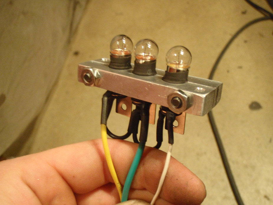
Light bulb "shroud"...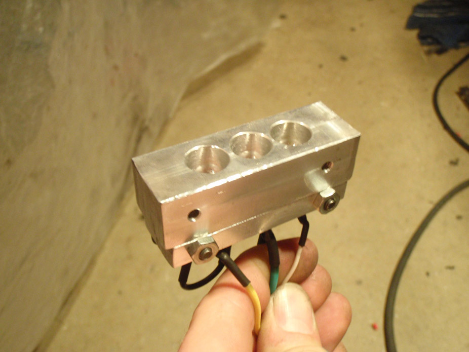
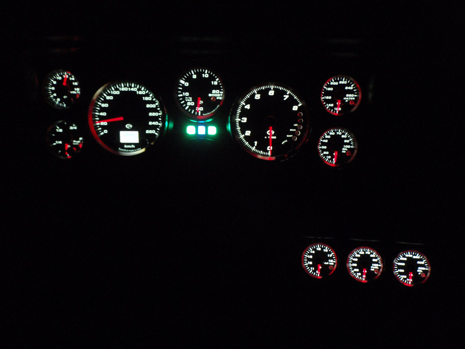
Stepping it up a notch, have some vids of the gauges....
8-21-2011
Here's the first part of the gas tank mod, didn't get as much done as I wanted today.
General concept is something that the OEM's have been doing for a long while in the single-tanked sports cars, and it involves a bit of a labyrinth, to try and trap gas during accelereation and left/right turning. In my research a while ago I found it's been in use on a handful of OEM cars for decades, but the two that I remember off the top of my head are the S2000...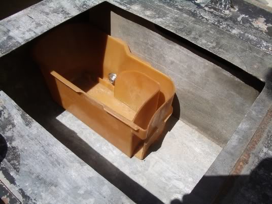
And the last couple generations of M3, like this E36 one...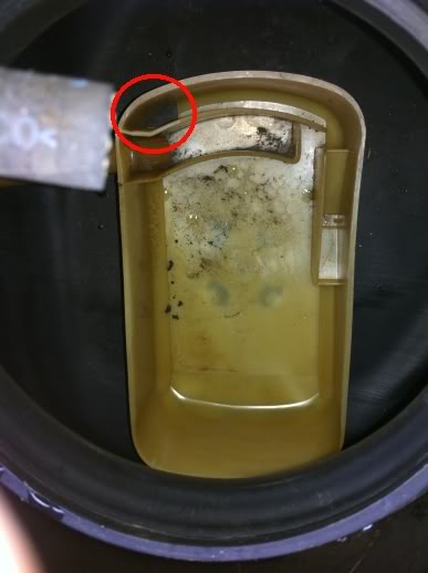
So had a crack at it...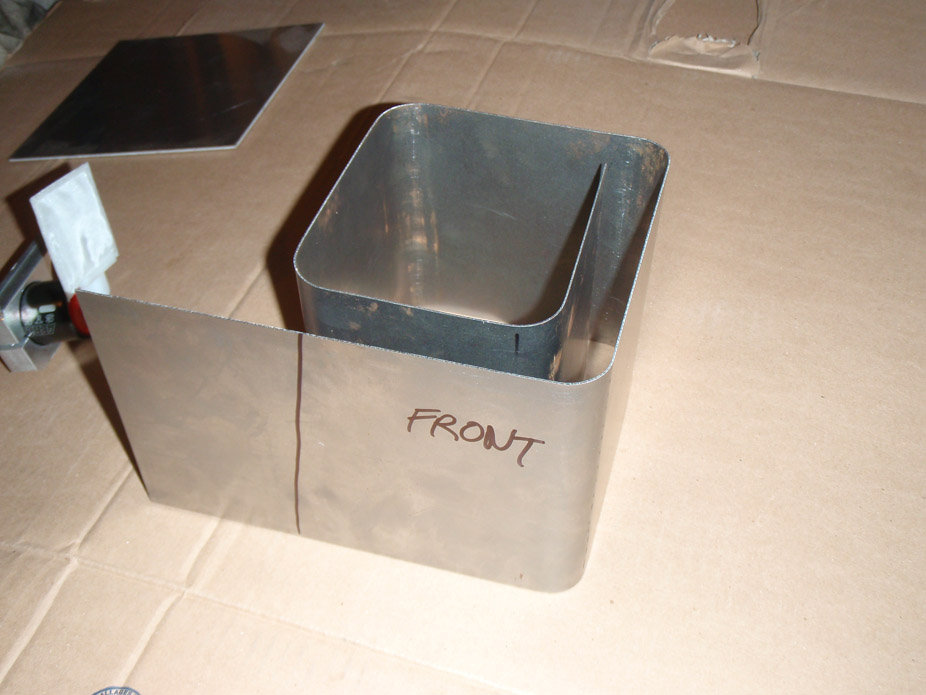
Fuel pump holding bracket to be welded to underside of bolt-on access cover...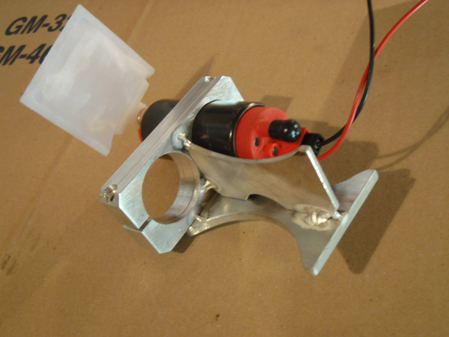
Hmm room for two, room to grow? Might as well think ahead while I'm starting from scratch...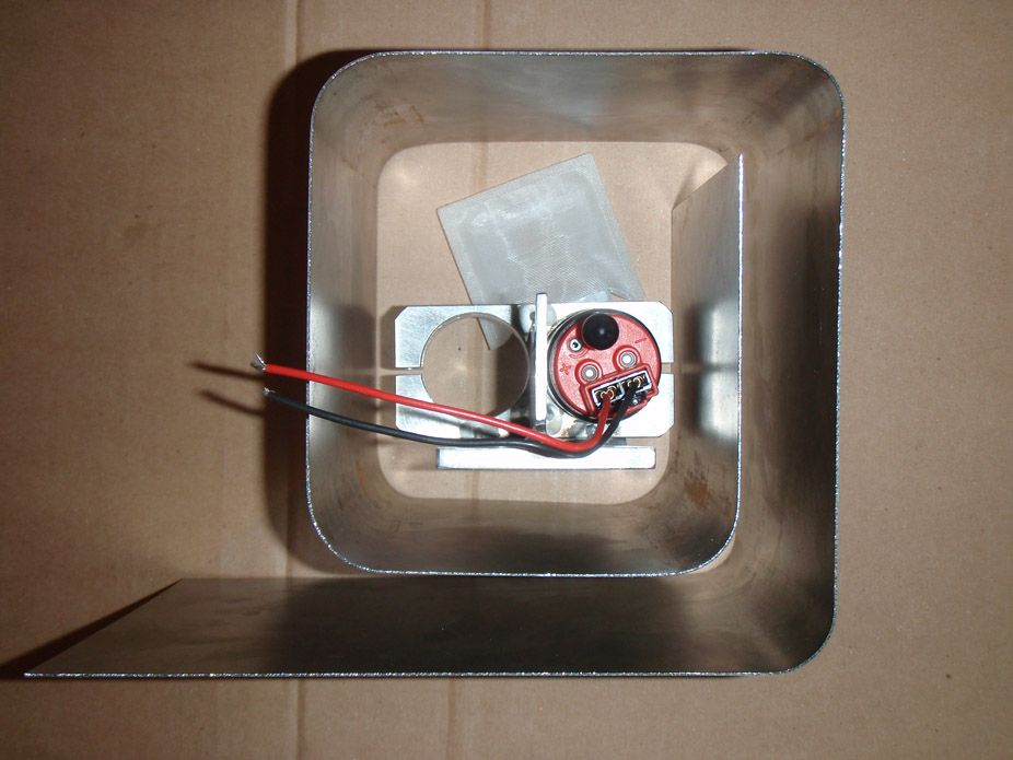
Reusing fuel level sender, easiest since my fuel gauge is programmable and the sender is already set for proper high/low height for the tank...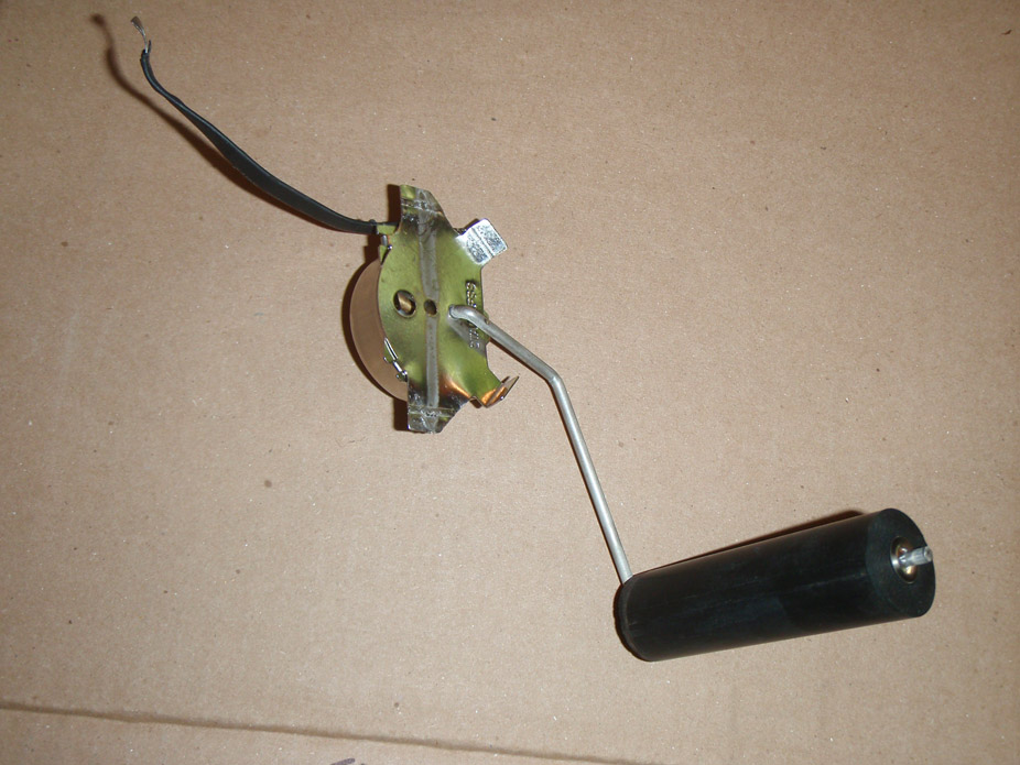
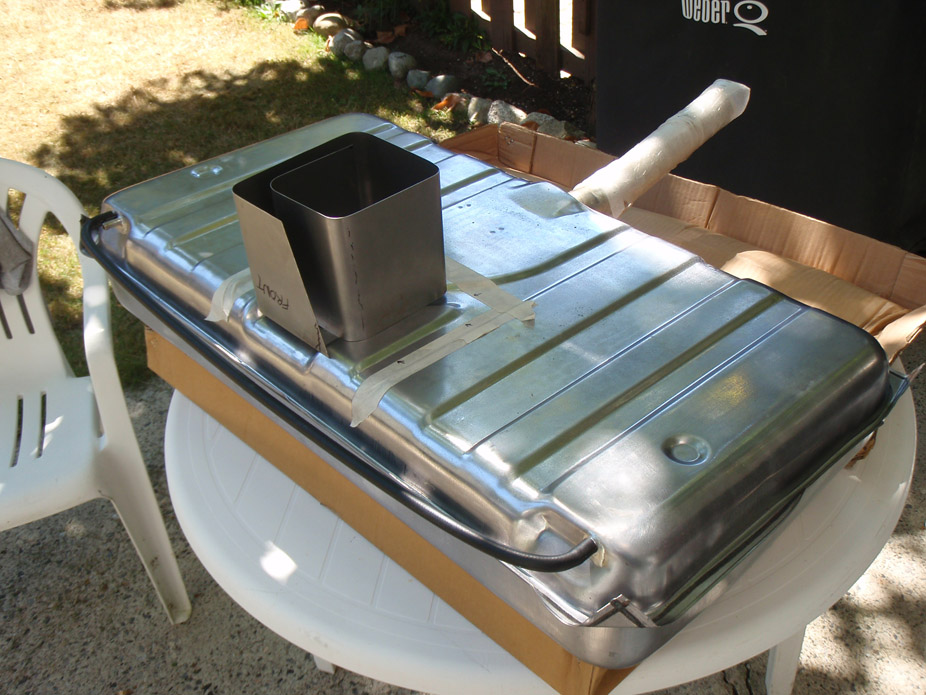
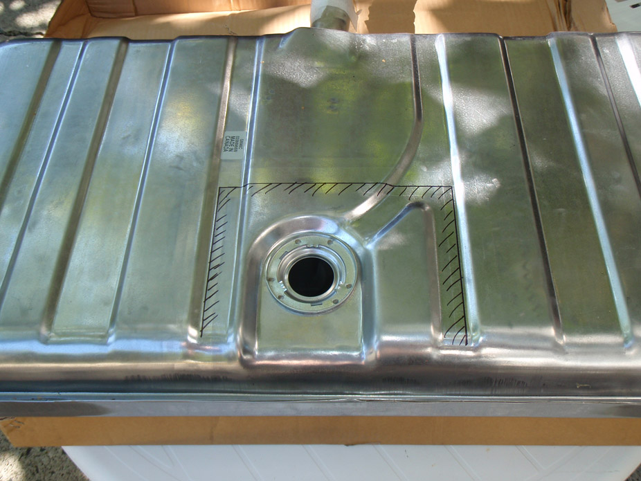
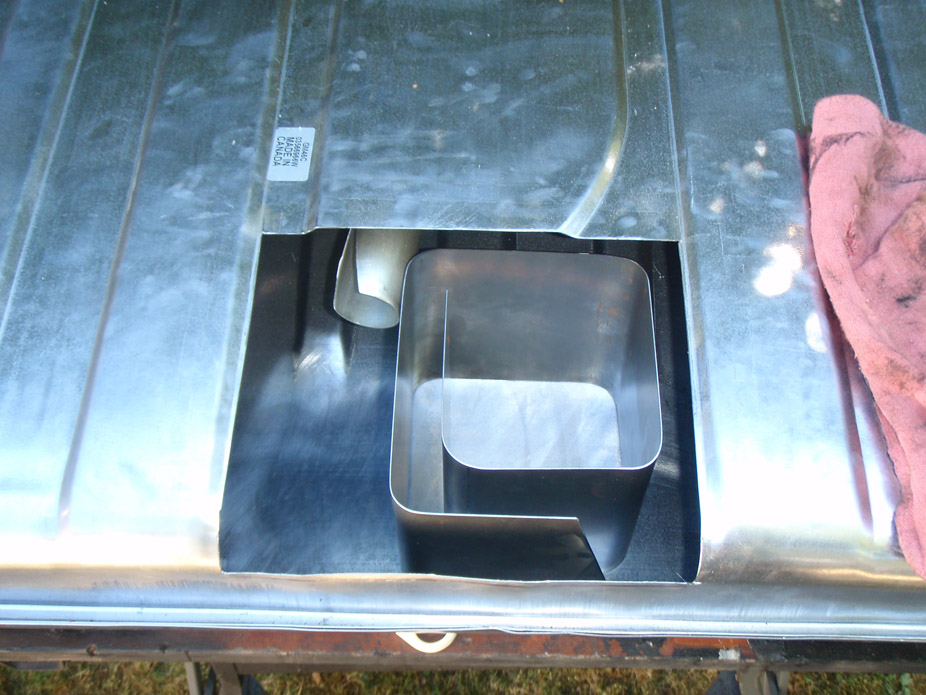
Tacked bottom to the walls, and going to run small beads or just tacks on the baffle bottom's perimeter to bottom of gas tank, don't want to put too much heat into the tank's thin walls. Once all welding is done in the tank, going to use gas-friendly sealer adhesive on all external welds on tank as well as the tacked joints on the walls of the baffle...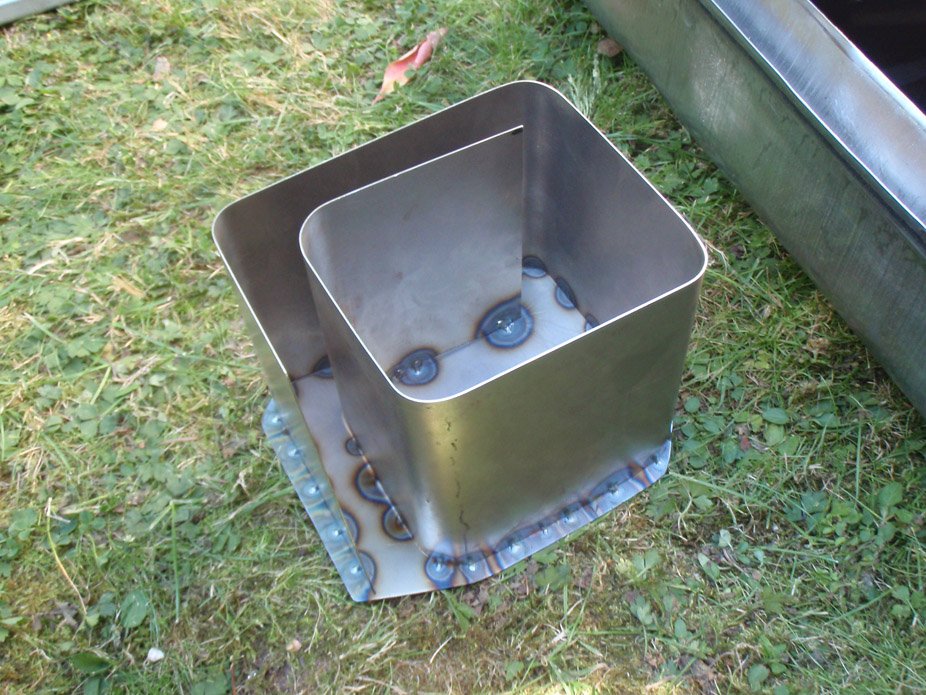
Had to trim very end of fuel filler tube to get the baffle centered. That's all the cutting and grinding I could get away with today...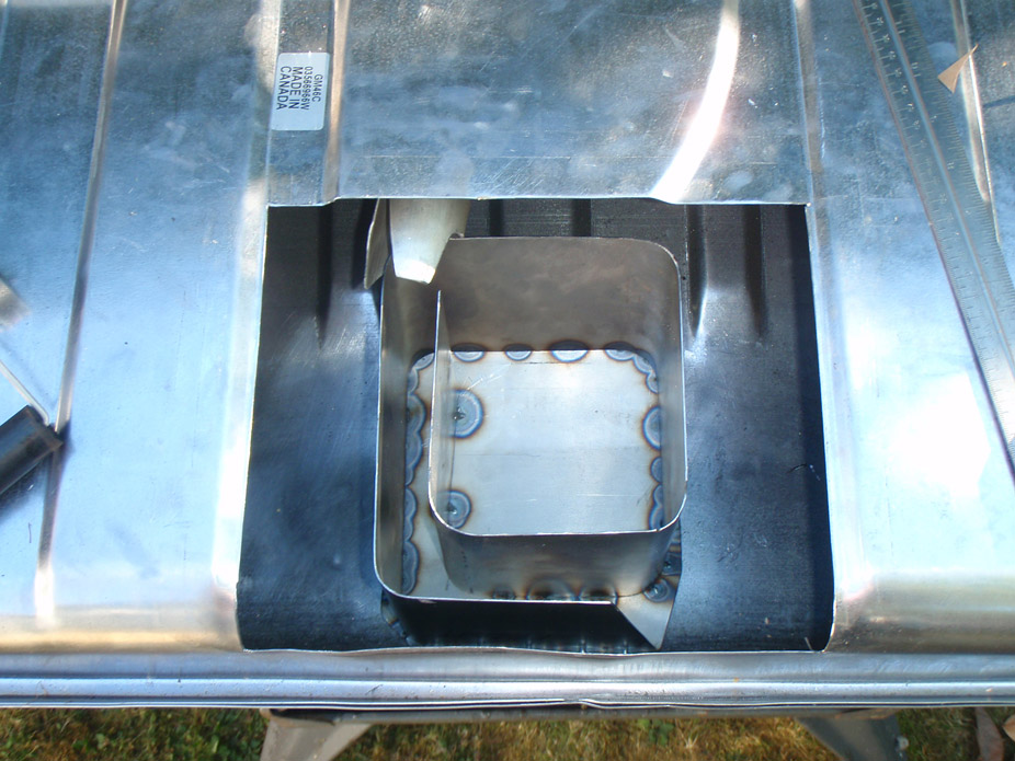
9-3-2011
Thinking of rebuilding a rear end yourself? DON'T. Just don't. Such a pain in the ***. Had to stop at setting the crush sleeve pinion preload because I don't have the right adapter for my big 1-1/4" onto the dial torque wrench driver. Need LOTS of cheater leverage...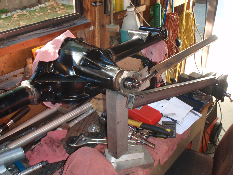
Friend came over so I just had to mockup the wheel stance, ~1inch tuck, gonna look tough.. but need to stick meatier treads under there for sure...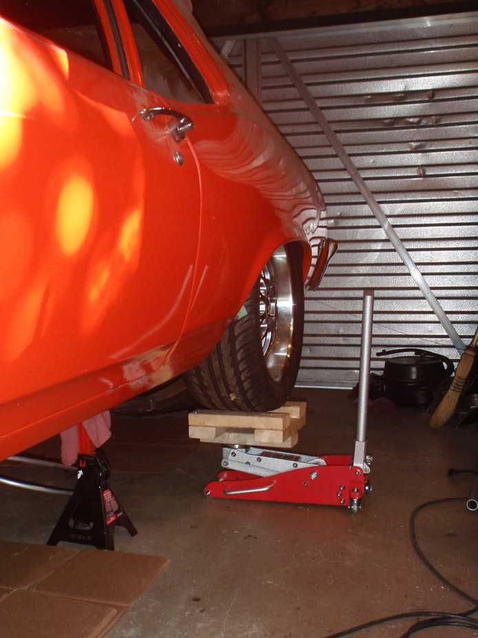
9-20-2011
Hey guys sorry for letting this thread get stale, had to take a couple weeks off to finish up my last school course, but now that's officially done and I'm completely free to work on the car.
I graduate 2nd week of November, and I am GOING to be driving this thing to grad, which I figure would be fitting since I started the whole LS conversion about 2weeks after I started engineering school... 5 years holy ****!
Rear end is still being a bastard. It took me about a week and a half checking backlash, wipe pattern, pinion depth and taking pinion into work to press off bearing/adjust shims/press on bearing. Then I finally get the pinion depth and wipe right, and start tightening down the pinion nut at realize the bigger pinion bearing is complete junk. Koyo unit, as far as I remember I didn't drop the cone side or anything but it has a consistent tick when the cone side is spun in the race. Used aluminum bearing race driver and did every thing carefully, have no idea what happened. Long story short I got new Timken bearings, which spin SILENTLY, such nice feeling pieces, should've just gotten those right off the bat. Even the brand-spanking new smaller pinion bearing without any ticks or sounds is just plain loud when spun.
So gonna make better-sized smaller pinion race driver, install that tonight, hopefully wrap up the rear end within a couple days. Also have a 4-link setup in the mail. And also have been bandsawing some sheet metal at work for the gas tank. Pics will follow soon.
That an acceptable update? haha
9-20-2011
True that about hobbies (car, biking, beer, friends) PLUS school... something has to give somewhere, hence the sporadic updates here hah.
I was stuck between 3.73's and 3.90's, but I have the Camaro T56 and I figured with the 3.73's it'd put my 4th, 5th, and 6th gears just slightly out of whack regarding cruising rpm's. Marktainium has 3.73's and likes them, but he also has the GTO T56 with slightly different gearing ratios. A couple guys on Lateral-G/Pro-Touring were saying either way T56 feels good with 18" rims and either 3.73 or 3.90... I chose the higher just cuz I'm not going for all-out top speed, and traction will be an issues regardless . To quote Mark: "1st is useless, 2nd is getting there, 3rd will still chirp or break loose".
Clint I think he might've been referring to reusing the crush sleeve when mock-assembling everything for the mesh pattern checking. Silly me threw out the original larger pinion gear so I didn't have it around to bore out and and make slip-fit... that woulda made the entire process much quicker. Then again I have to go into work everyday anyways so waiting for the press wasn't too terrible.
I went with the Chris Alston G-Link, has good adjustability and minimal work to get it in, although it does require welding to the framerails as well as some tabs on the axle tubes. Everyone and their dog was recommending the DSE Quadralink rear end, but the floor sheetmetal under the rear seats would need to be cut up and reinforced, the trunk between wheeltubs needs to be chopped out for the shock/panhard bar cradle, and the axle flanges need to be cut off to slip on 3 brackets per axle end which all need to be 360*-welded... simply too much work at this point. I figure for my purposes I wouldn't even notice the advantages of the DSE "Swivel-Link", so the Alston triangulating 4-link won.
I figured I might as well while I have the whole rear end out and a (new) gas tank not installed, I'll end up dog-earing the gas tank corners for tailpipe clearance. It made sense to do right now because I'd want to do it anyways eventually, and to get the stance I want I'd have to have lowering blocks, which just aren't cool. Better ride quality, great ride height adjustability independent from shock settings, stronger for high hp, adjust pinion angle for lower height as well as anti-squat... all made sense right now.
9-25-2011
Small update, feels nice to have some workbench space again...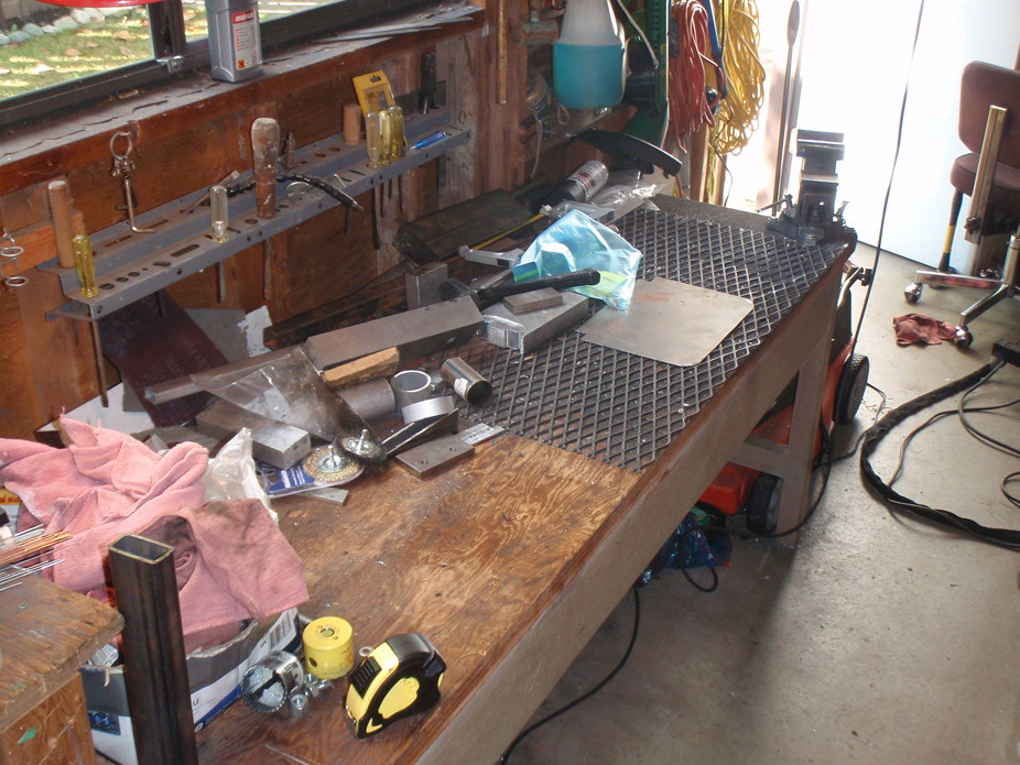
... cuz of this!..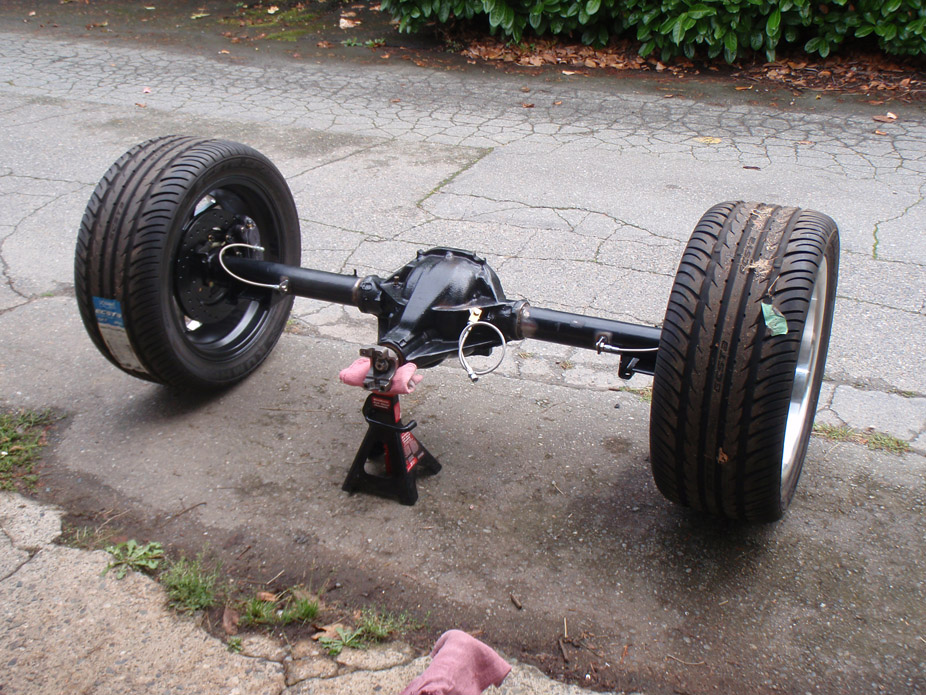
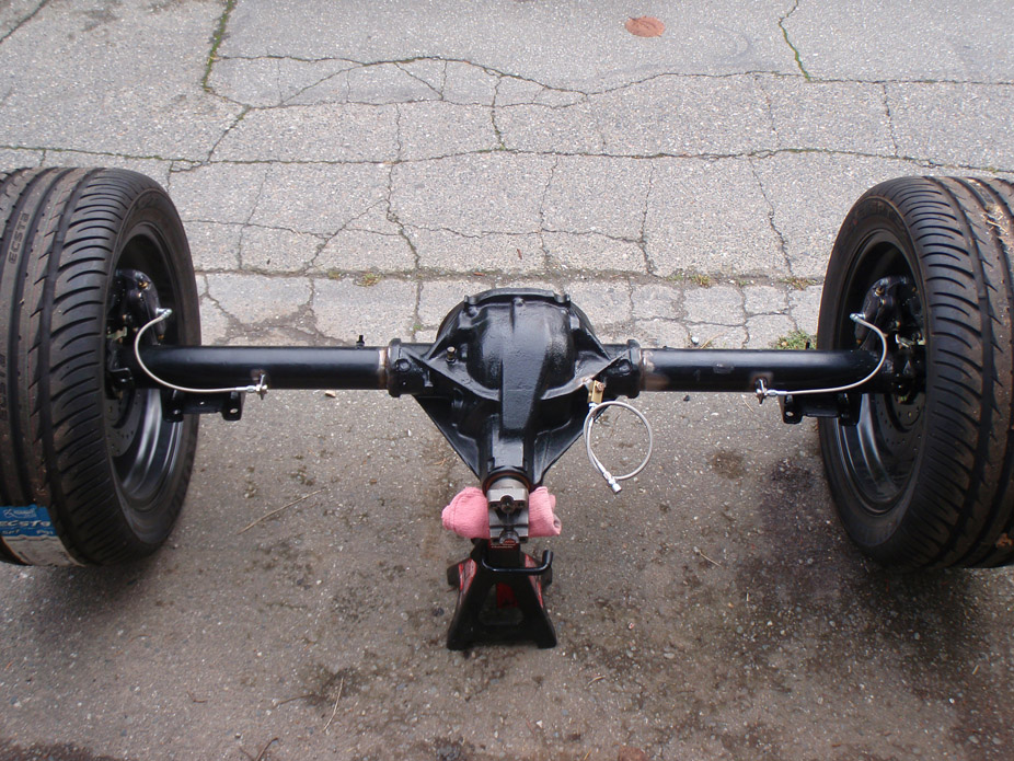
Still waiting on the 4link so I can weld on the upper tabs and give the rear end its final coat of paint.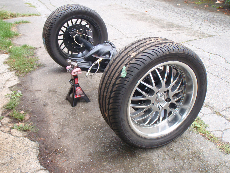
Rotors look so small in there...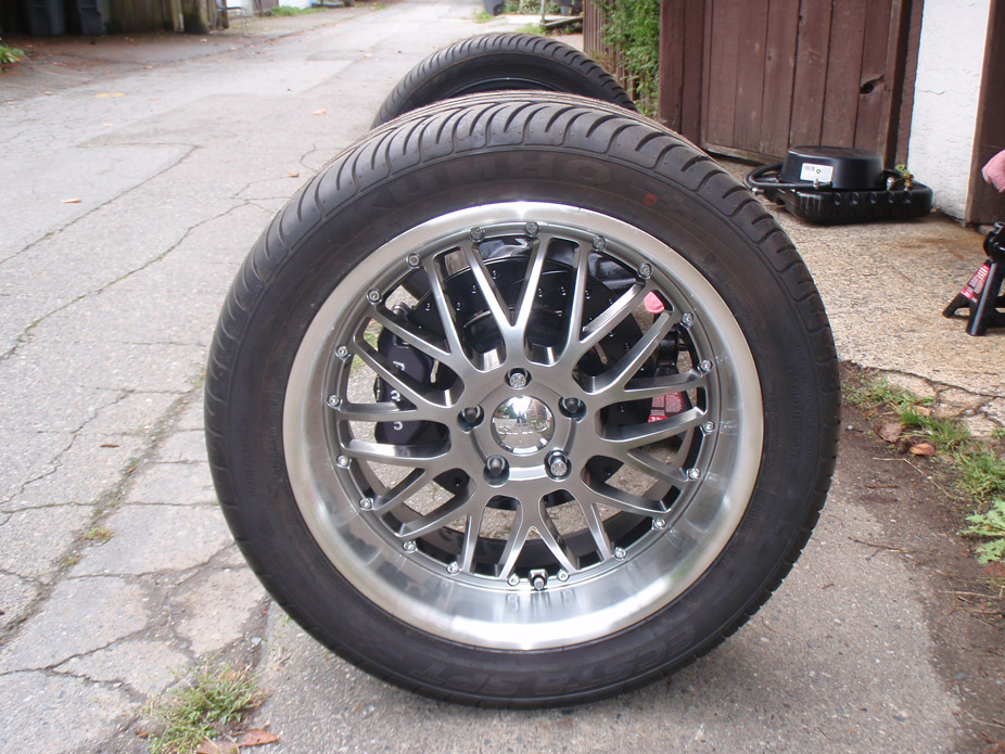
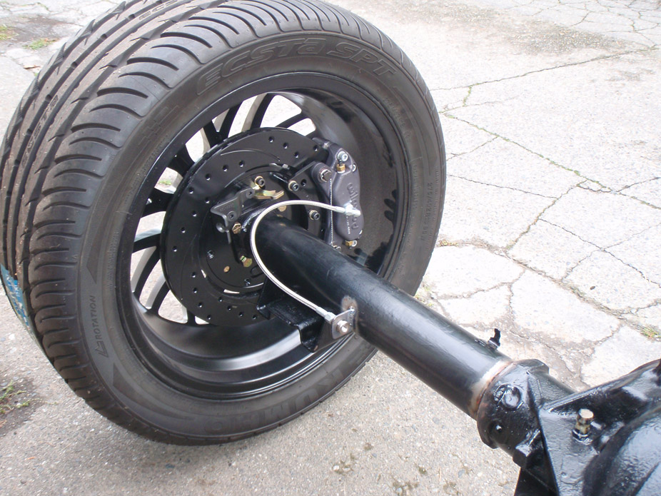
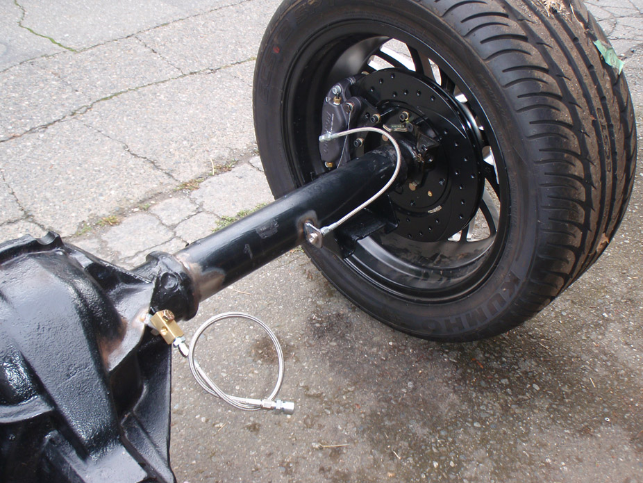
10-4-2011
Oops went a bit crazy with the jigsaw. Corners notched for tailpipe clearance for the 4-link...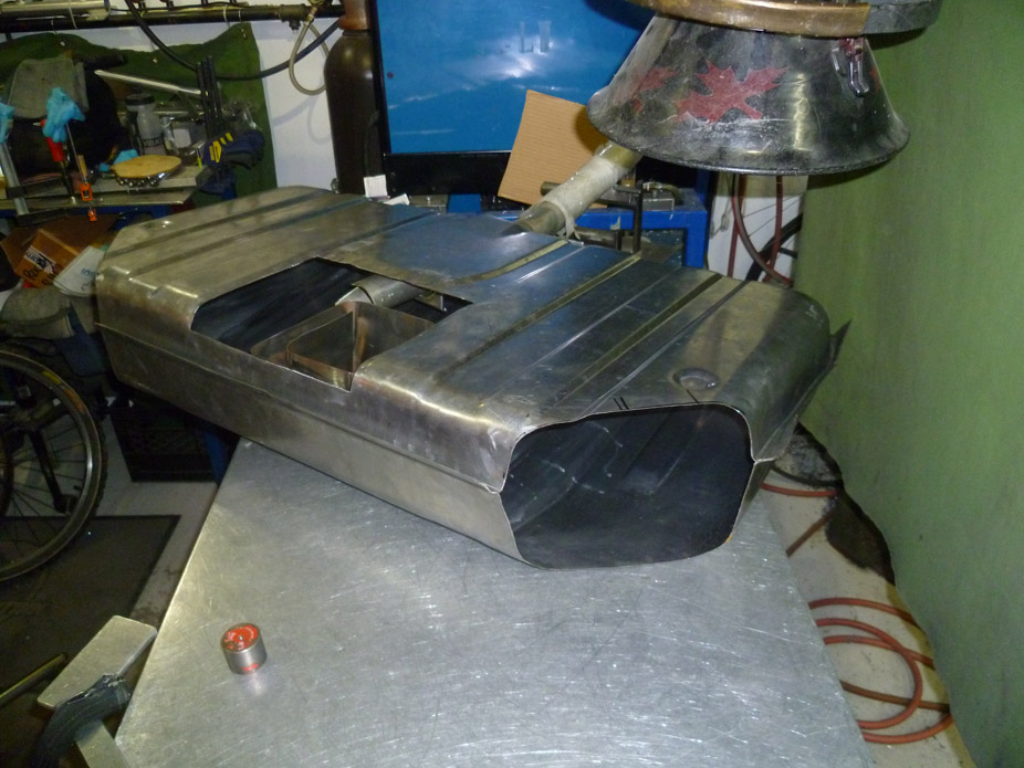
Recessed access panel plate. All studs are actually socket screws which heads are tacked to some 1/8"x3/4" flat stock on the backside, which was then tacked to the sheetmetal, to keep everything rigid and prevent the screws from rotating or pulling through...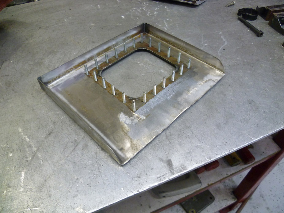
Stock-replacement fuel level sender reused...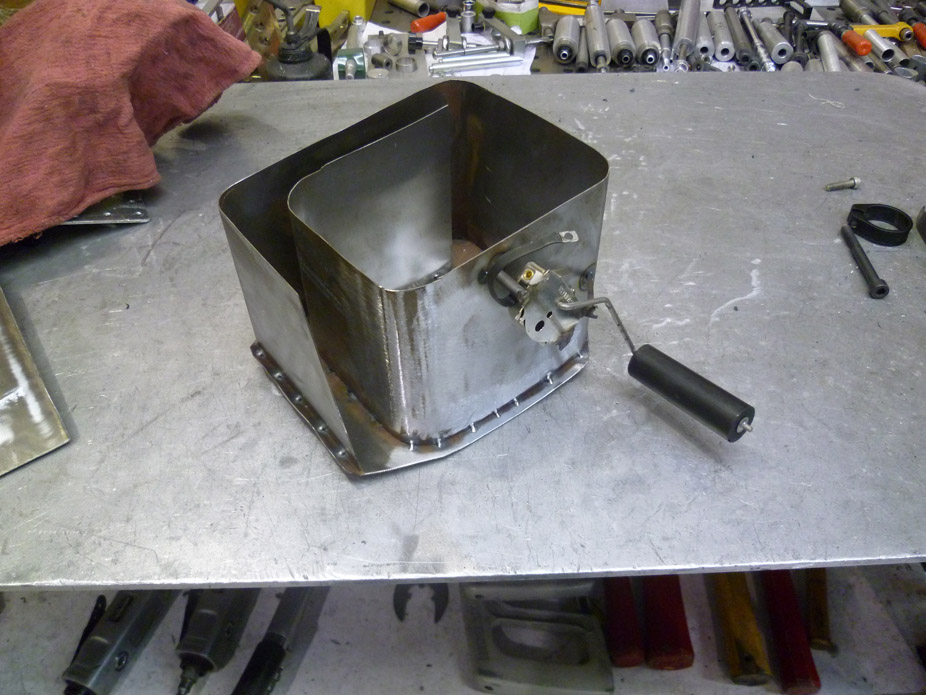
Fuel pump holder drop-in assembly..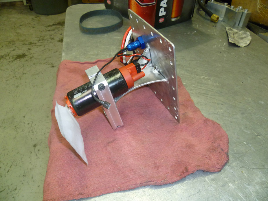
The -8AN bulkhead fitting goes to a hose barb and FI hose to the pump, the -6AN bulkhead fitting goes to a J-shaped 3/8" tube that returns the fuel to the bottom of the sump chamber.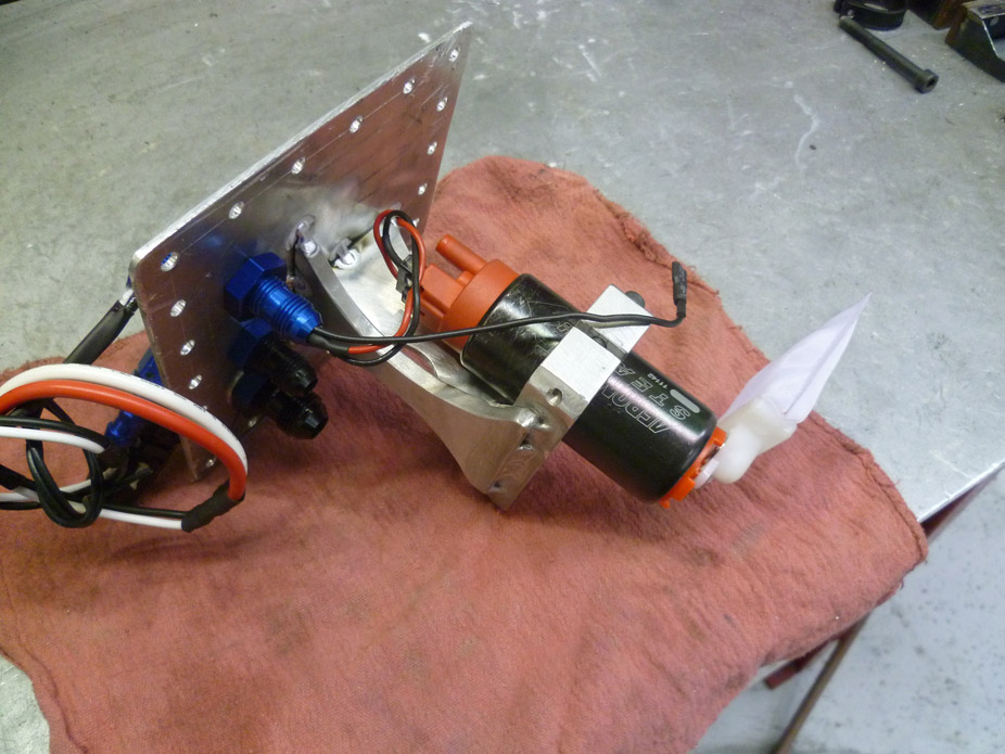
Bulkhead fitting for wires has this gas-friendly caulking/sealant stuff, hopefully that doesn't let anything leak out...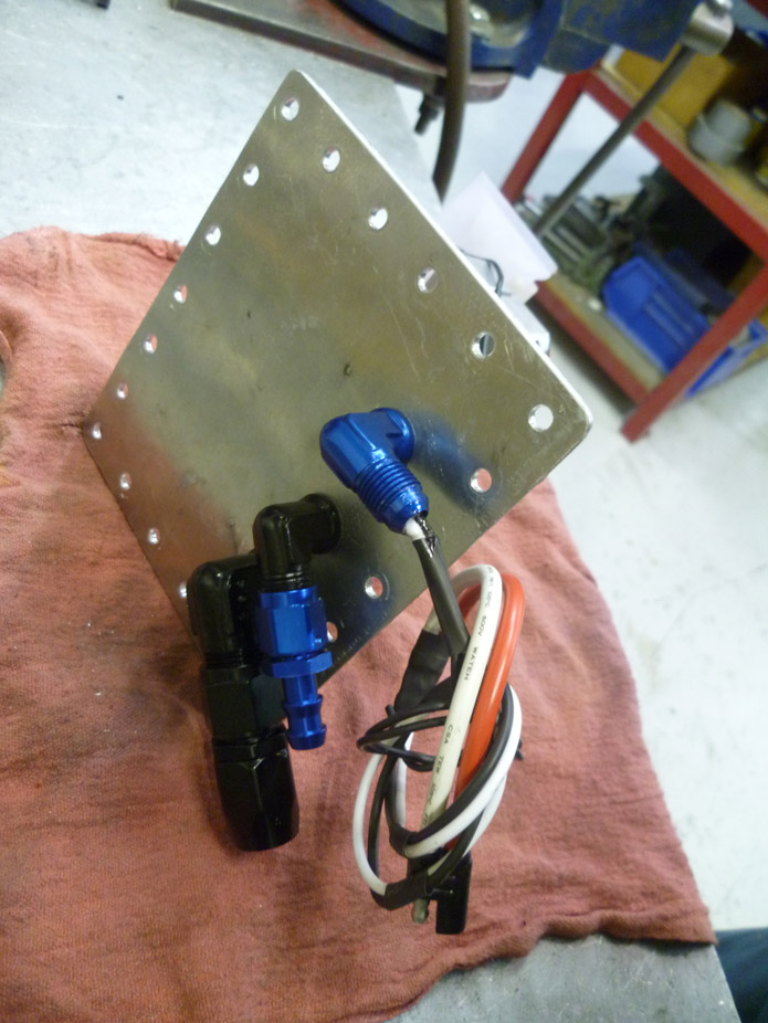
Welding this sheet sucked used 1/16" tungsten, 45A, and 0.035" MIG wire as filler, and had to go slow. Talk about having to develop steady hands and a sensitive pedal foot in a hurry!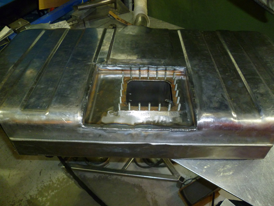
20gauge is finicky **** so not the nicest looking weld but should do...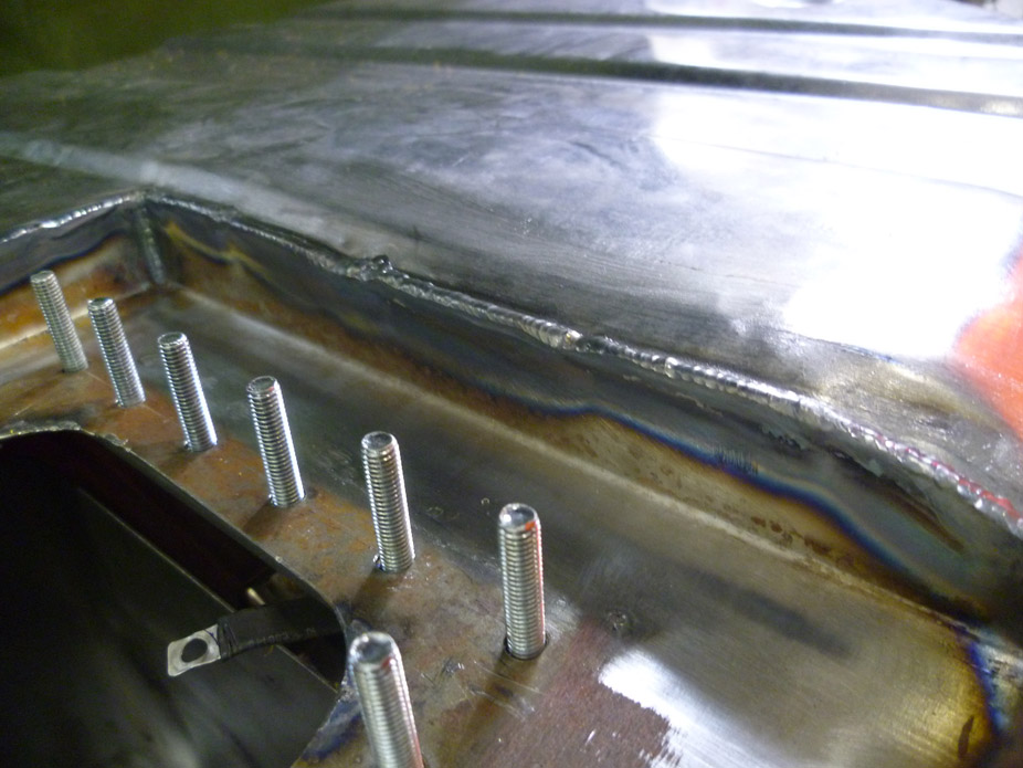
10-5-2011
I'm a little weary of sealant breaking off, but I'm not ruling it out, just on the fence. Will have to call around locally to get some quotes.
I'm also on the fence for gasket on the bolt-on plate. the gas-friendly sealer stuff I have "cures" somewhat gummy, which is good for a bit of flex for wire movement coming out of the bulkhead fitting. It might work well also as a gasket for the bolt-on plate because it doesn't cure hard.
On a side note, need to change the harness plugs for the injectors from the stock truck mini-Delphi connector to the LS3 style EV6/USCAR. And thus arose some hilarity.. I always knew UPS was a ripoff but, seriously??......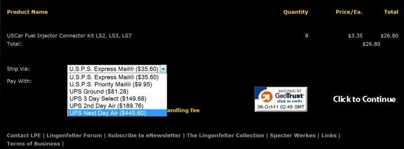
10-6-2011
Fuel return diffuser tube..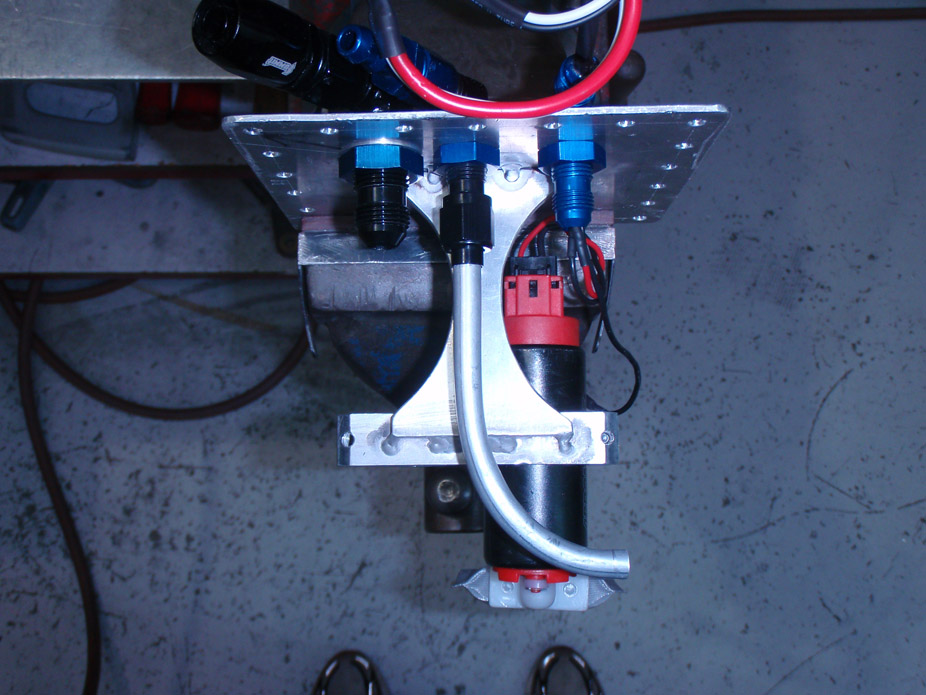
Welds progressively got smaller and tighter...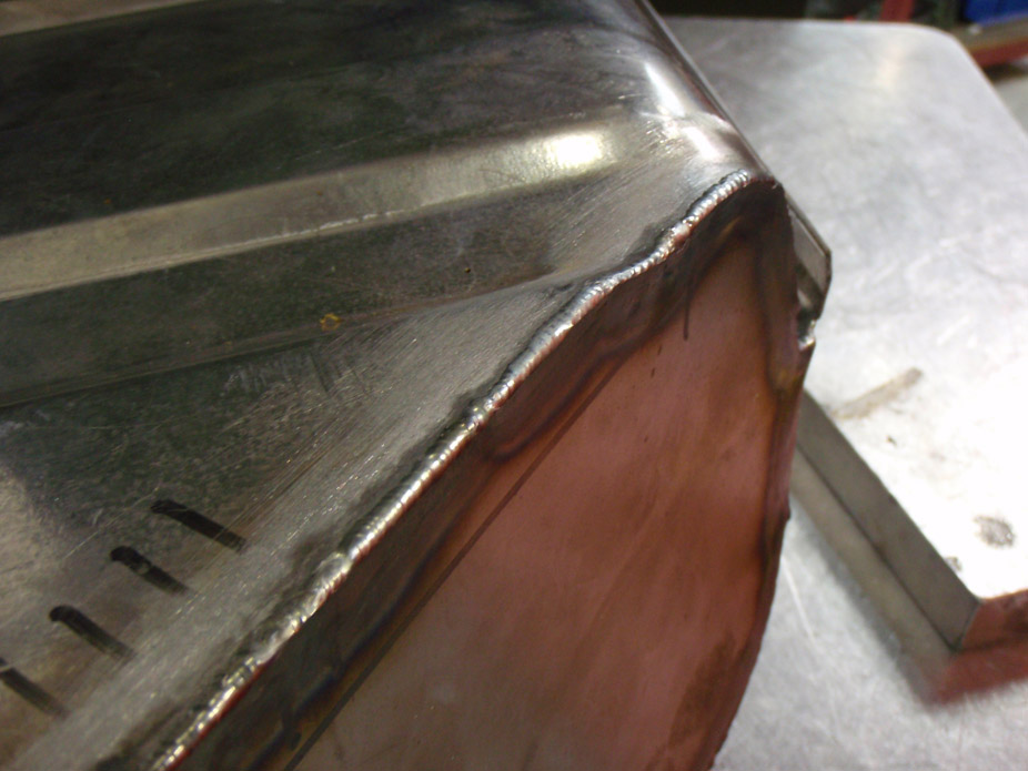
Conveniently my best welds on the tank were the last 4" I had left. To put this in perspective, the Sharpie lines are the regular fine-tip Sharpie marker, not a huge marker...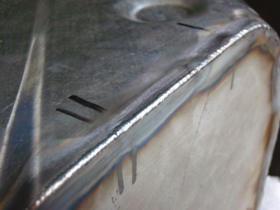
Done! Feels good. Now to get some serious progress done over the long weekend up here in Caaanaada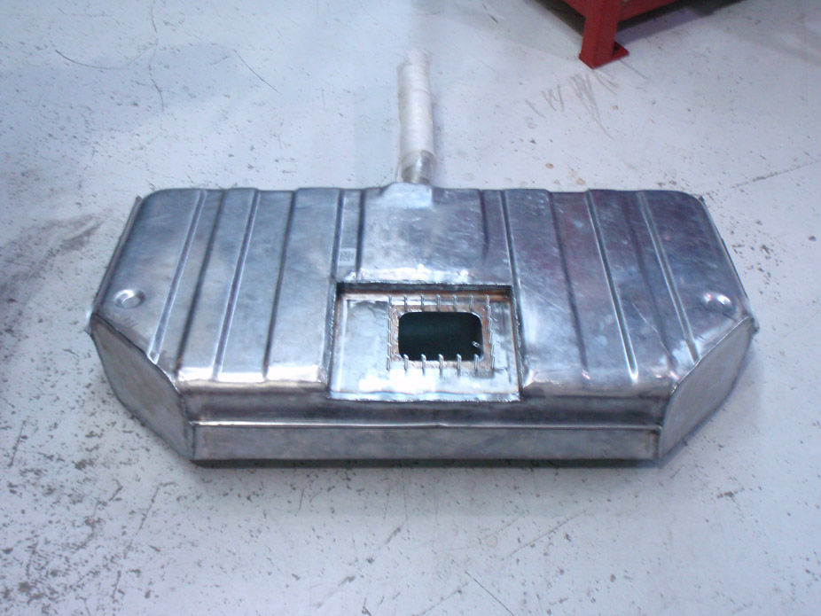
10-22-2011
Couple small things to update on. Spent most of the afternoon fixing stuff on the daily driver, but got a bit of Nova work done...
Stripped, smoothed, and painted 2nd gen Camaro tilt column, just need a Nova rag joint before it's ready to bolt in (direct bolt in otherwise)...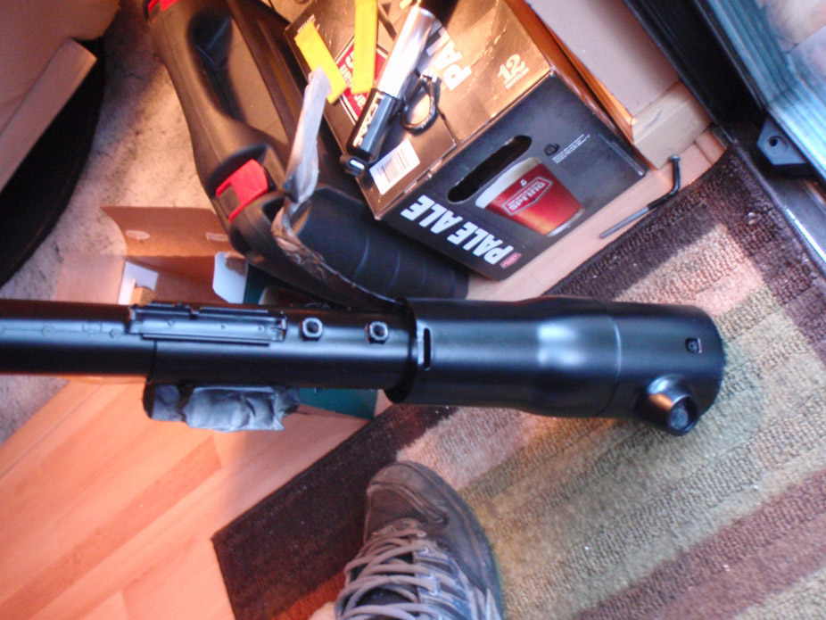
Putting 3 point belts in, no way I'm gonna use the lap belts hah.. got a pair of 240sx front belts for $10, but the ones in my daily driver were in nicer/newer looking condition so swapped them out, here they are. The belt extends reeeeally far so it shouldn't be a problem to have the shoulder loop mount high and back where the stock shoulder strap for the lap belts is anchored...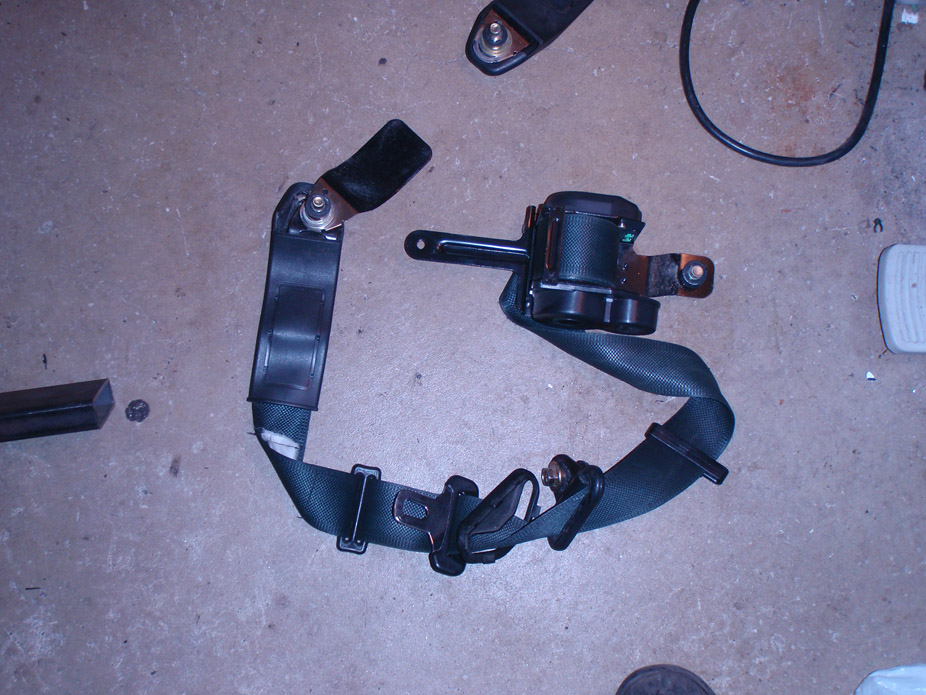
Tank leak tested, seam sealed, and painted...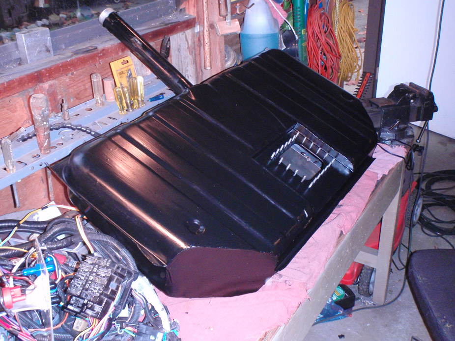
Still waiting on the damn 4 link, so mocked up the rear end to see exactly how low I could get away with. Here is a little measurement guide to show the room on stock Nova tubs with an 18" wheel and 275 series tire.
I'll end up running the rear at a ride height probably 1-1.5" higher than this, so this setup shows the rear end going slightly into bump. With the 4 link and coilovers there should be 2.5"-3" of bump travel. Funny there is still quite a bit of fenderwell room to go lower, just run out of space between the axle and frame...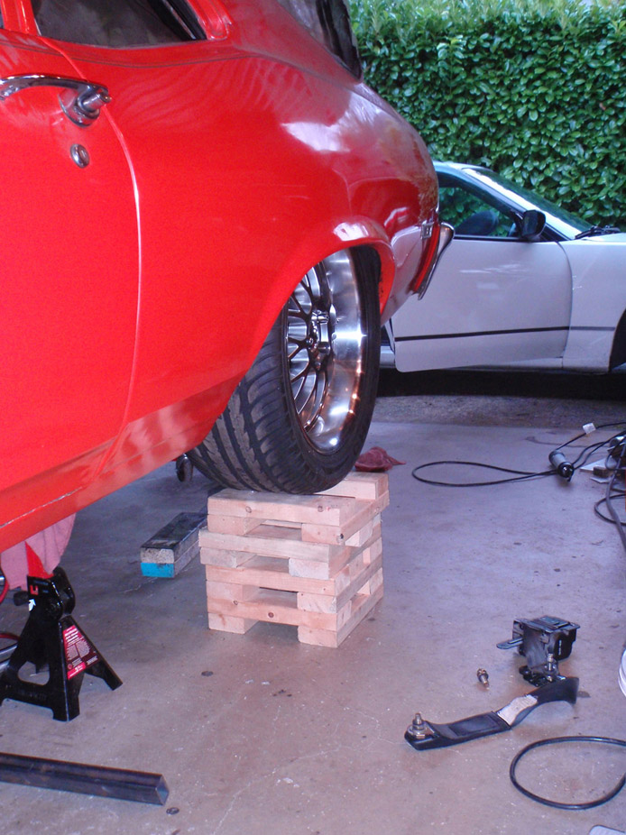
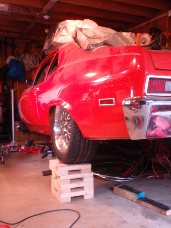
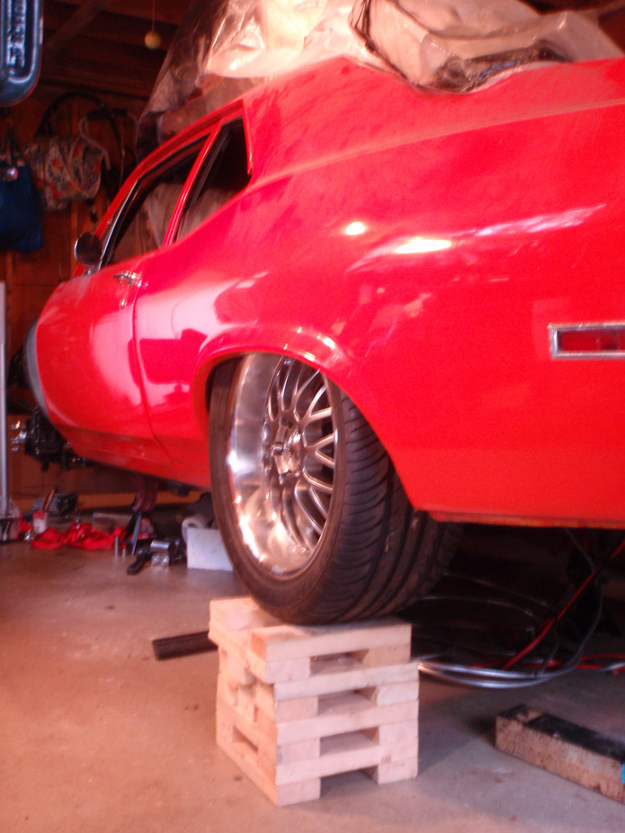
Tucking the rim around 2.5" inch, would ideally like maybe 1" of rim tuck...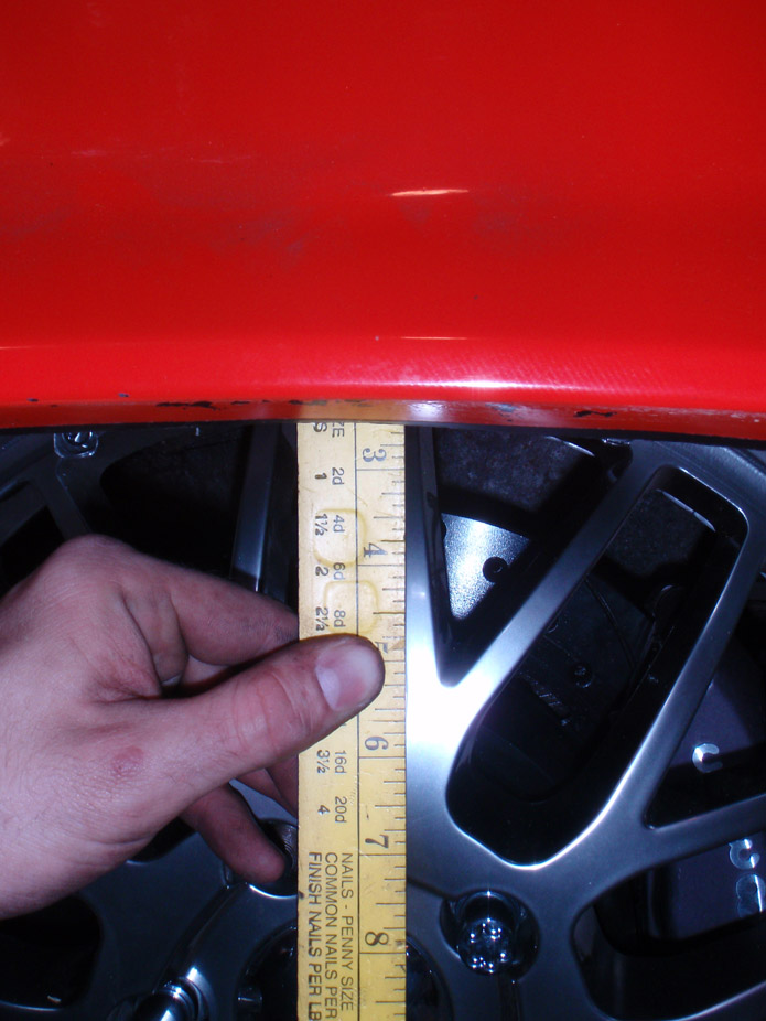
About a 1/2" of clearance between the sidewall and the flat, vertical part of the inner fender well..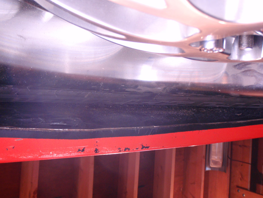
Still about 1.25" clearance between sidewall and inside of inner fenderwell (ruler is about 1.25" wide).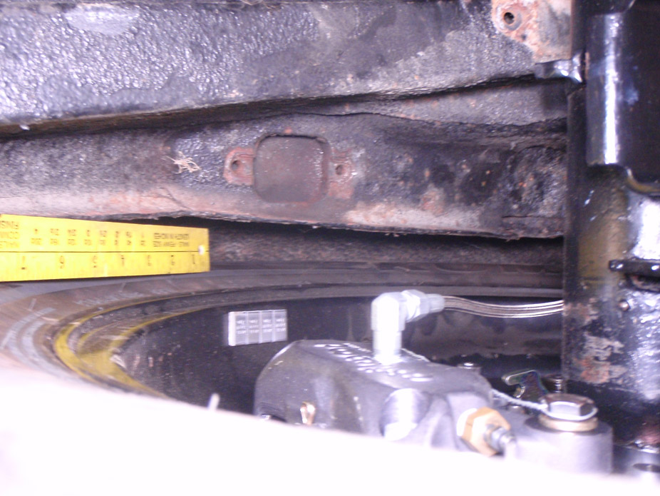
Bad angle, but about 2" of bump travel left until axle bottoms out on framerail. The coilovers will have bumpstops and I will be running the axle about 1.5" lower (further away from framerails) than this.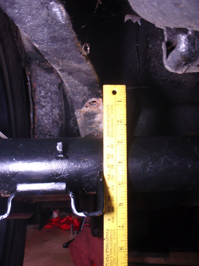
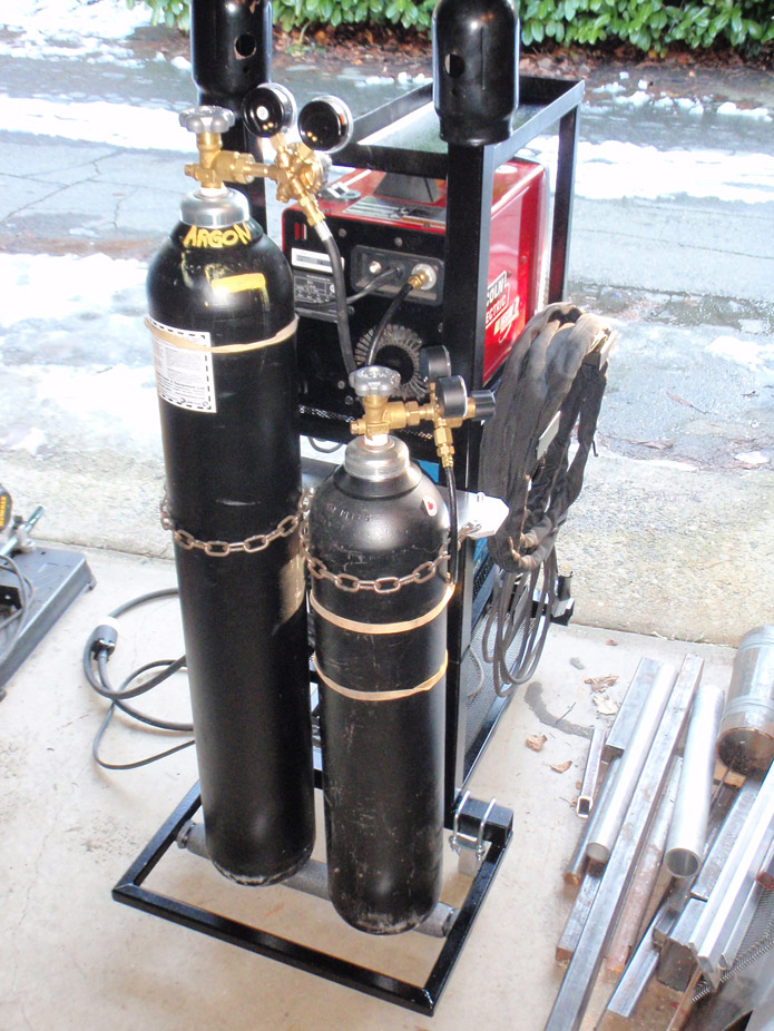
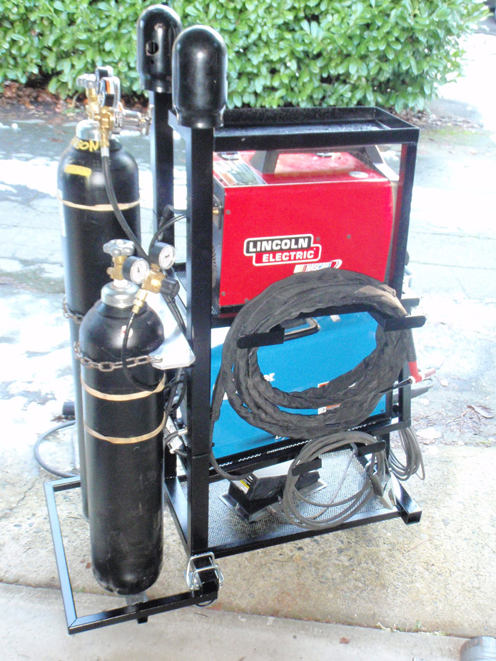
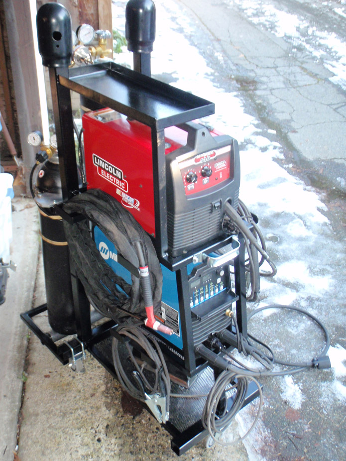


Wow thanks for sharing!
Posted by Diggymart on 3/3/19 @ 12:40:25 AM