You must be logged in to rate content!
8 minute(s) of a 70 minute read
7-25-2008
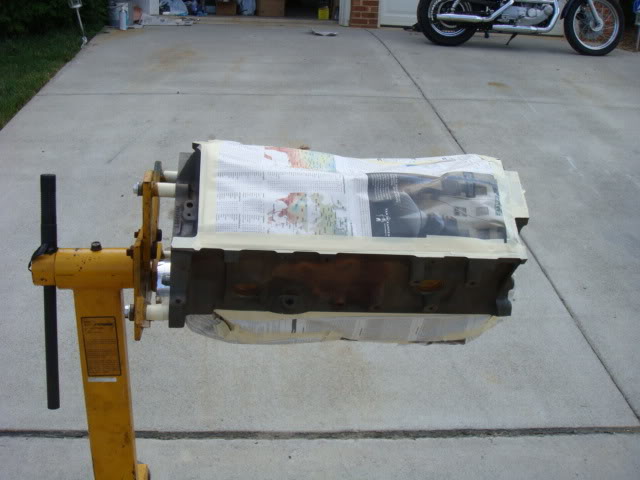
Final motor assembly is this Saturday (Tomorrow), so I had to get the block painted. Here's the block all taped off and ready to be sprayed.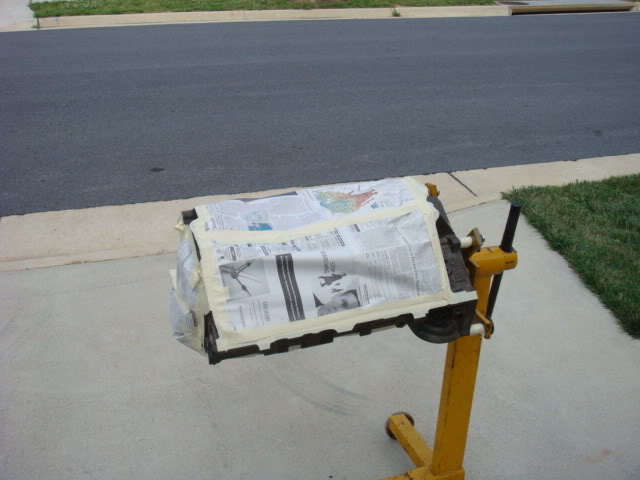
Here's my waterpump all nicely powder coated and ready to be updated with the E-drive!
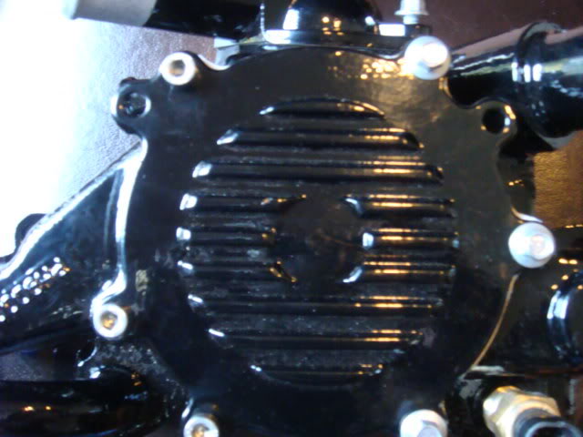
So which bolts do I go with? The left are SS Allen heads and the rights are the stock bolts with Ultimate Chrome Power Coat.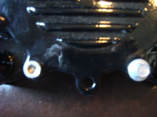
Will and I started the top end assembly and here's how it went!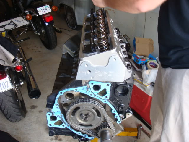
Torque to spec, with the Victor Rentz Head Gaskets in place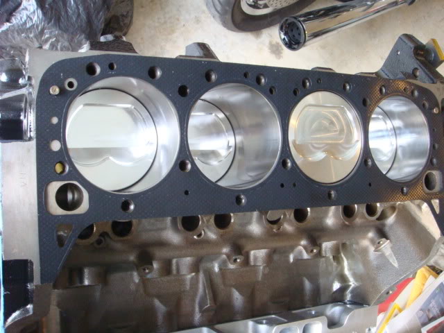

Once the heads were on the next step was to lubricate and install the lifters, 7" push rods and then roller rockers. I'm using the Crane 1.6 Gold non-self aligning on recommendation of Tony Mamo of AFR. He said that I needed to use a lightweight aluminum RR, rather than the path of the steel Pro-Mags, here's Will adjusting the RR's to zero lash and then making a quarter turn and locking them down.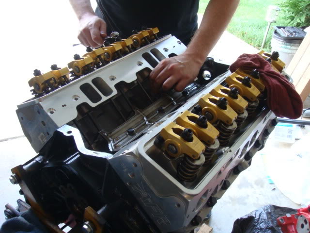
After the adjustments on the roller rockers and guideplates were all complete we next ran into a problem of trying to get the rear main seal to fit between the engine stand and the block.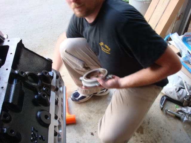
So I asked a neighbor to bring is pickup over and put it in my driveway so we could roll the block down to it and take it off of the stand and disconnect the stand mount to allow access to the rear of the block.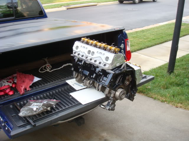
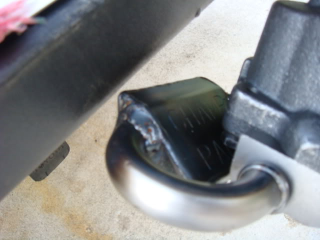
I was careful not to touch the oil pump and pickup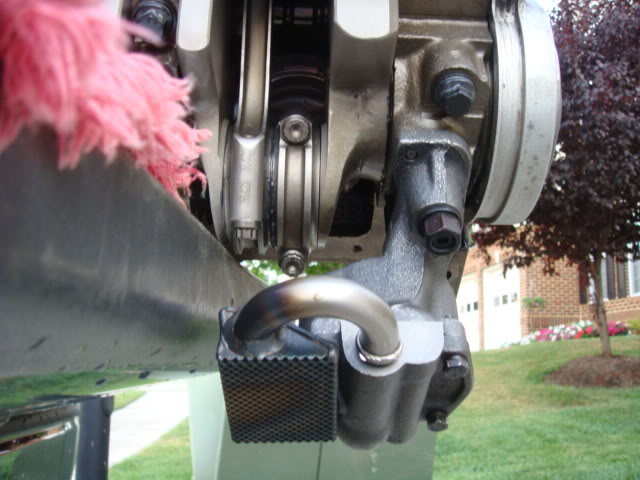
After that was all said and done, we went back into the garage for the intake. When Will port matched the intake to the heads the gasket he used was the Felpro 1284 and here's a picture of that gasket.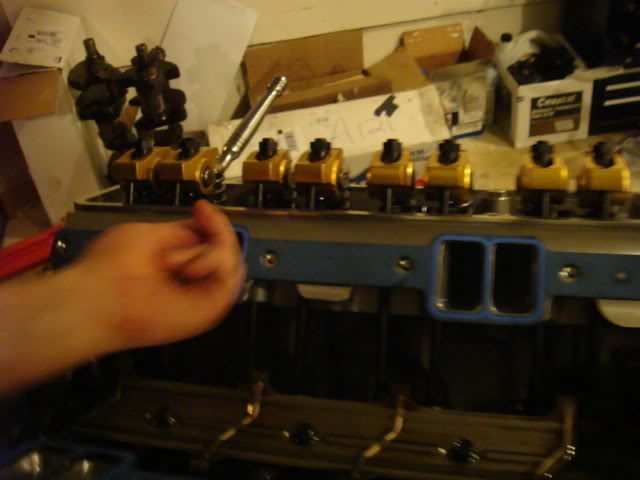
Will saw that the top of the intakes were being covered up by the gasket so we then shifted gears to the 7777 gasket and it lined up perfectly!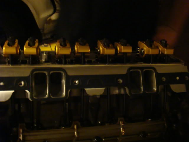
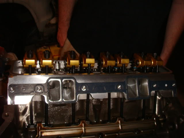
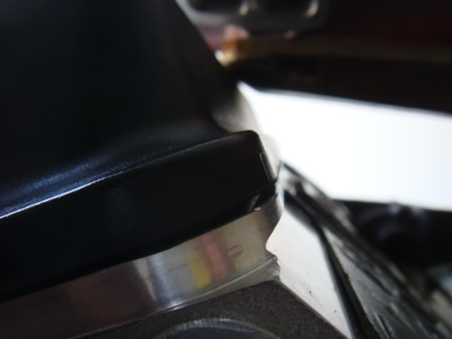
The intake would not fit on the top end of the motor because of the AFR head design so Will had to grind some of the intake in order to get it down on the heads. The area that he did the grinding on had plenty of meat to work with so it wasn't a big deal at all.
Here's the ledge on the AFR's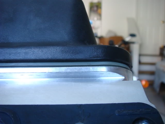
And here's the grind area of the intake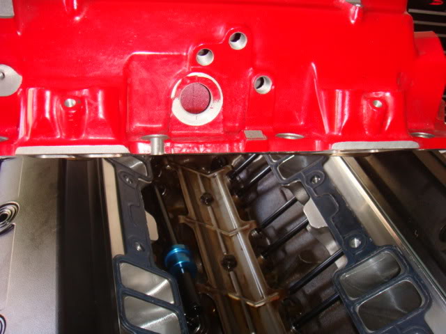
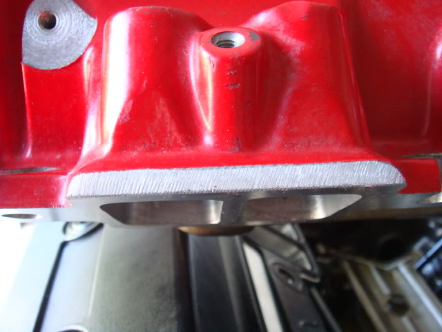
Will was aware of the issues with the MSD opti's so he decided to ensure that the internals were good. Once he opened it up he realized that the screws holding the rotor were not tight at all, and behind the cover we found a victim.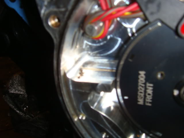
It appears to be a dead Mosquito.
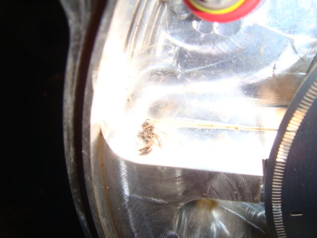
Once that was all cleaned out and the rotor was locktited down, we moved to the motor mounts then headers for clearance. We installed the started as well before hand to make sure we could get it in due to the oil pan clearancing issues.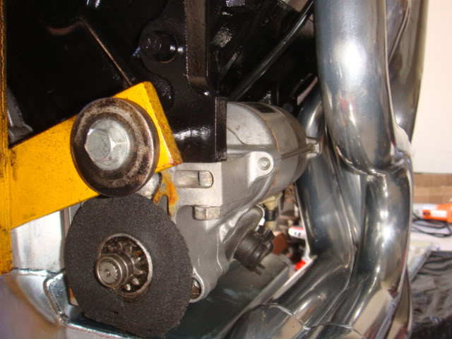
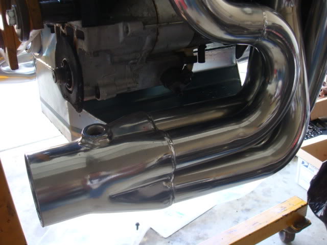
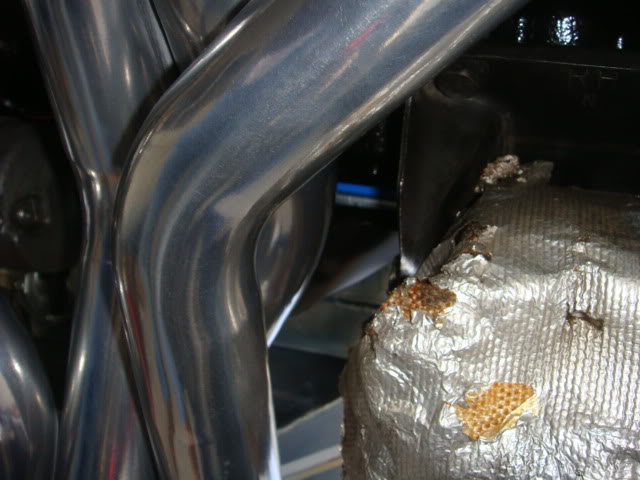
The bolts that go through the motor mounts need to be reinstalled with the nut forward, and not to the rear because it won't clear these headers unless you gring the bolt down.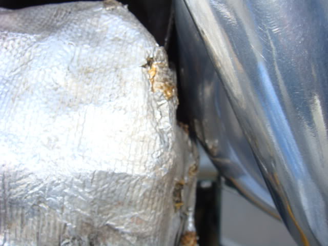
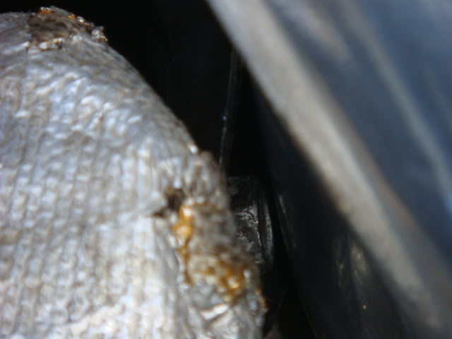
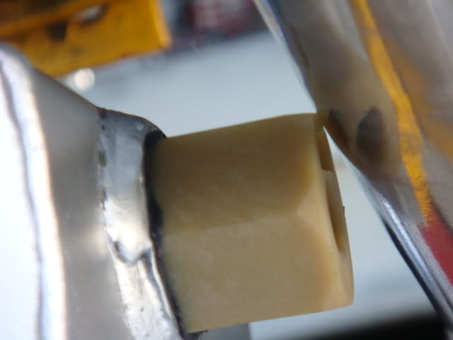
Due to the location on the oil pan where Champ installed the oil level sensor it touches the headers. Not sure if I'm going to plug the hole and tune this sensor out, or cut the nylon nut to fit.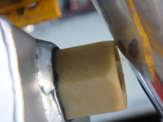
Here's the finished product, with a few small exceptions and as soon as I can find the bolts for my oil filter adapter, I'll prime the motor.
I should be installing this next weekend if I can figure out a way to get it over to where my car is!.......LOL
The headers are Exotic Muscle LT4's with coated extension and high flow cats ceramic coating on everything. I have pictures of the headers and extension on page 1 of this thread. I have a total of 4 O2 bungs, one on each header and one on each extensions, just like the LT4's came with.
The cam was what Will profiled and had Reed custom grind, there's a picture of the cam on Page 6 or 7 of this thread but the specs are:
Cam info.
Reed TM284/286HR12
[email protected] - 284/286
[email protected] - 232/234
Lobe lift - .340/.340 (.544/.544 w/1.6)
I/C / L/S - 106/112
I also run the Caddy lifters which are suppose to be VERY good, compared to the LS7 and other aftermarket offerings. I didn't want to go solid but wanted to be able to rev as necessary and not worry about the top end components.
The blue thing sitting in the lifter galley is an oil pump priming tool. I just sat it out of the way long enough to take the picture of the intake on top of the motor. It won't stay in there, I promise! Thanks for checking it all out!
The bung on the oil pan need to be place on the front angular or forward wall of the kickout. Mine was placed at the rear of the kickout sidewall and it's right up agains the tube. I'm thinking that, because I bought an aftermarket composite oil level sensor, that I might cut it down at the right angle to clear the header. I don't think it would take much more than about an 1/8th of an inch to make more than enough room, but I'll see later on during the week if that approach will be what's best.
The oil pump that Will recommended was the Mil-18750, I ordered it through Summit and there on back order to it took a few weeks to get in. It uses the same type of pickup as the Melling M55-HV.
If your asking about the Oil Level Sensor, the clearance needs to be on the drivers side ~ 1/8th of an inch to clear the header. Either the header needs to have a dimple put in it to the right or the sensor needs to be cut down some to clear the wire.