You must be logged in to rate content!
10 minute(s) of a 70 minute read
7-20-2008
Well the day FINALLY came and Will showed up with all my goodies from the Machine Shop in North Carolina and various Secret locations around the country. Before we could start assembly, Will showed me my camshaft and pointed out the major differences with it as compared to most camshaft cores on the market. I have never built a motor, but I will say this was a very impressive and exhausting day. The camshaft looks like no other, that I've seen and I've seen one or two in my day. I was also sworn to secrecy about the specifics of the grind and other aspects of the cam dynamics that I'll have to Google and read up on just to get the "Big Picture" Anyway, enough of my lack of knowledge, here's some pics!
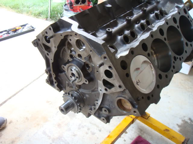
Setting the block up on the engine stand to get this party started!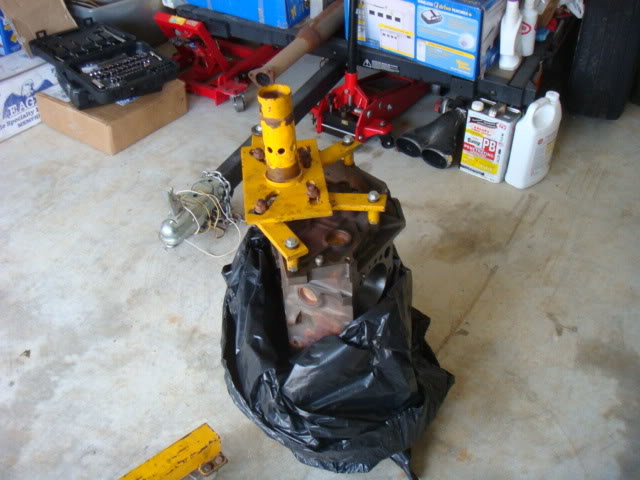
Cleaned the Mains as each Main Bearing was installed in the new block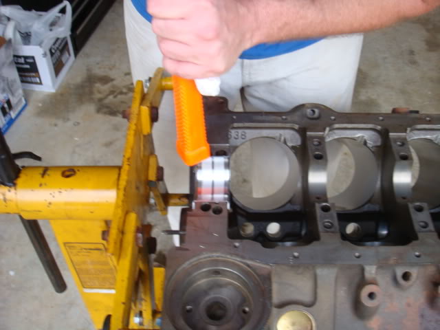
Will making sure that it's perfect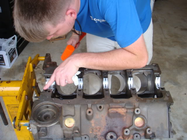
Will cleaning the crankshaft prior to install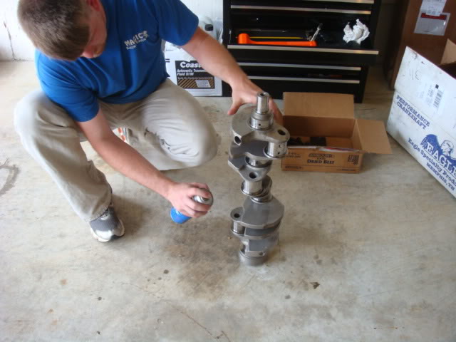
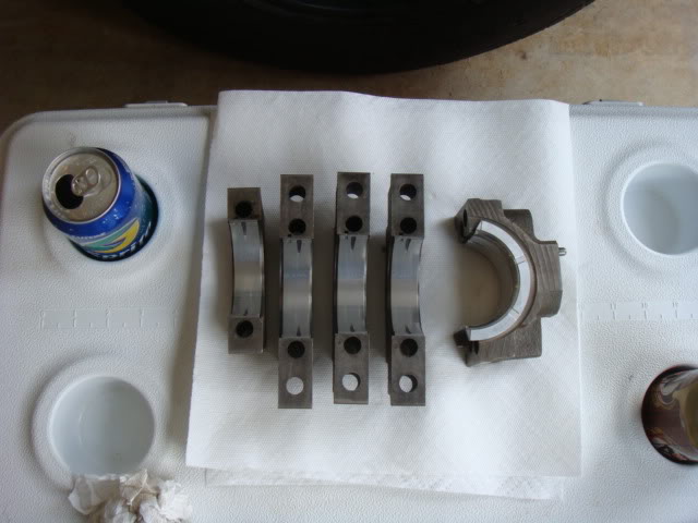
Caps and Bearings all ready to go
Lube and Prep of the mains
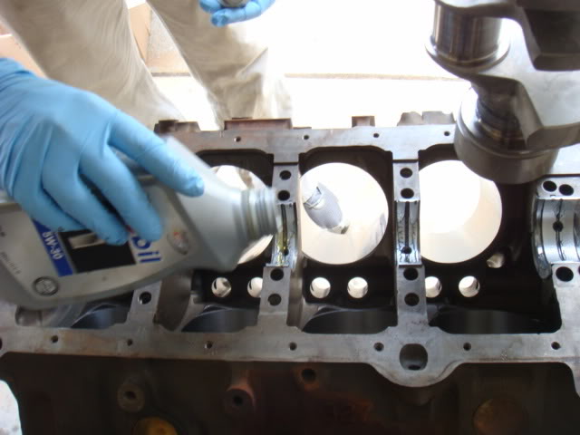
Landing the Crank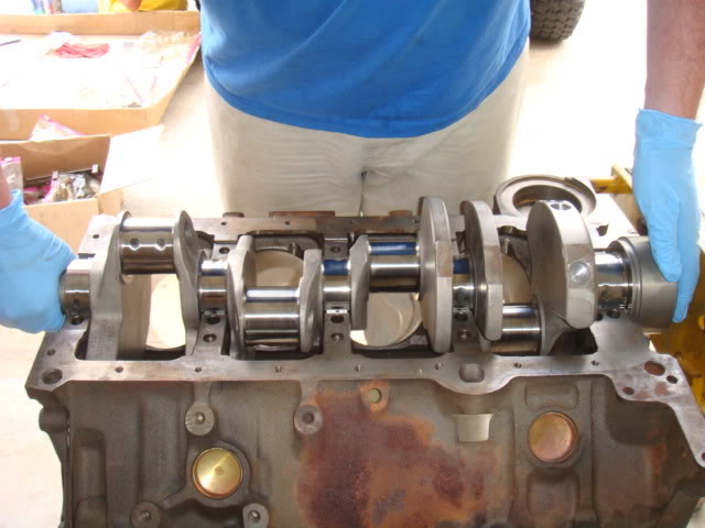
Torque of the main caps to spec, spec as called out by ARP was 75ft/lbs using assy lube.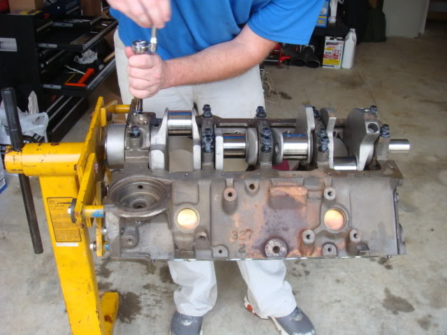
Setting up to measure Thrust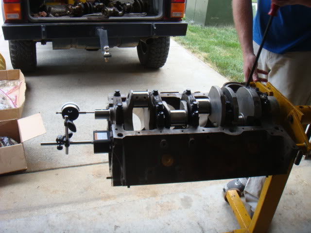
Total Thrust was measured at 0.007"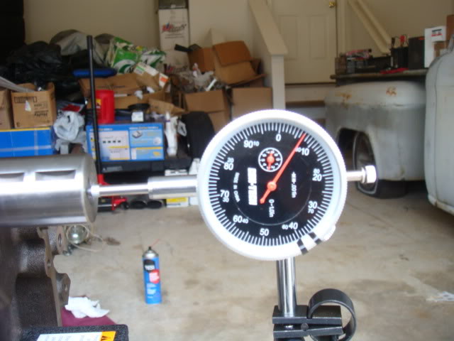
Next Will measured the amount of deviation that the snout had when the crank was turned, and I think it was so small of a number that I forgot, it was basically "Zero" anyway, here's the picture.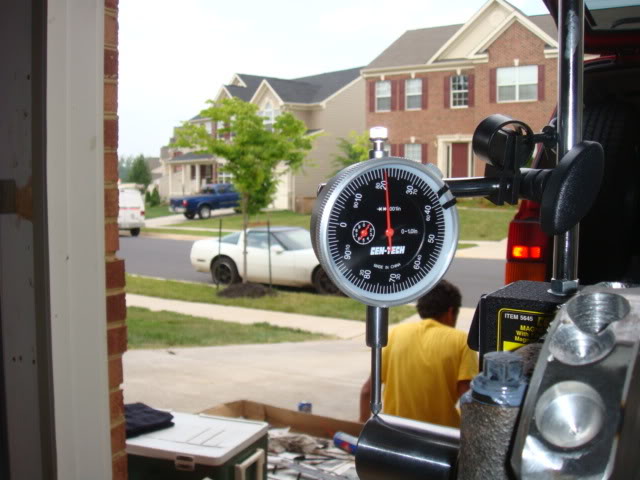
Cleaned the piston holes with some ATF in prep for piston installation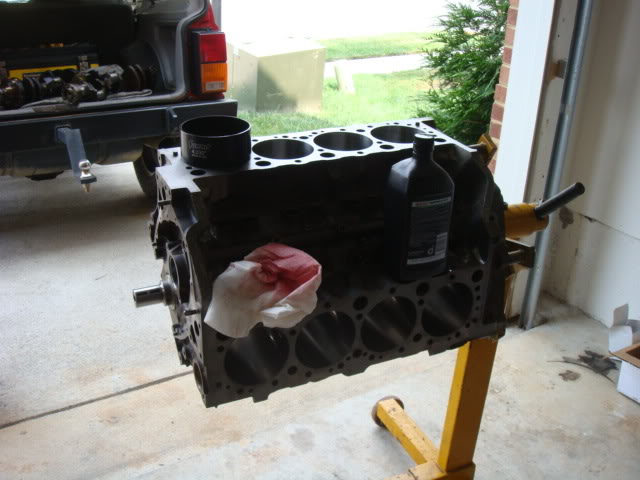
Will shipped the rod caps at a specific torque to the rods, so it took a little bit of effort to get them broken down so he could hang them on the block. He is TRULY **** about everything he does! (Good thing, not bad)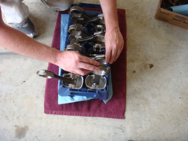
Will installing #2, wearing the Nitrile rubber gloves that I gave him and him hating it!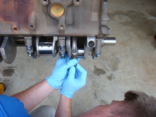
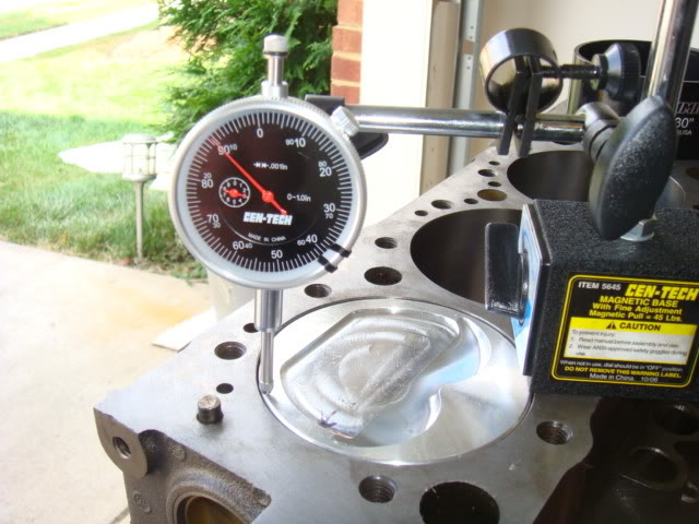
Will put #2 at TDC after install and checked the piston-to-deck clearance.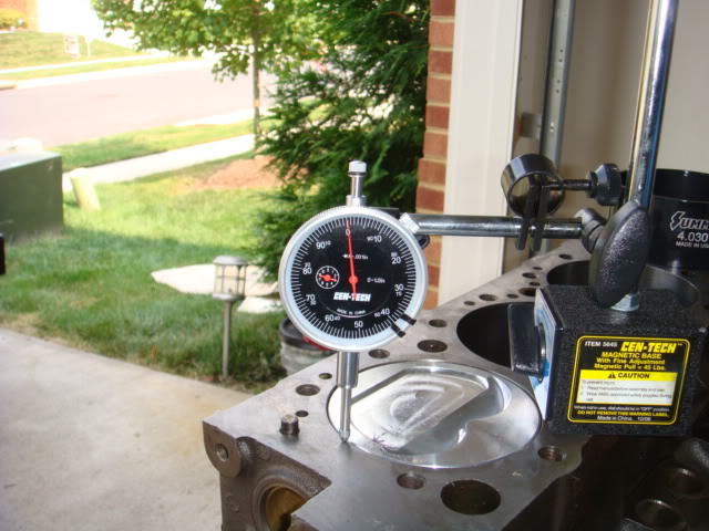
Bottom end at full torque and ready to go.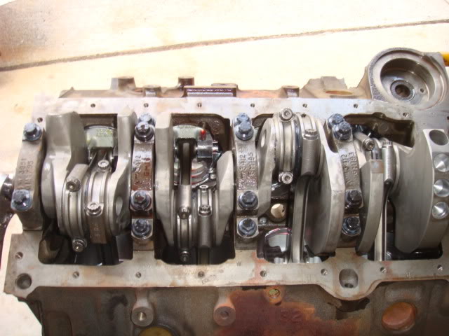
Pistons in the holes.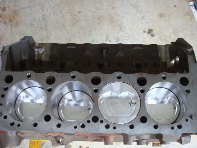
Classified Cam Install, It was so secret, Will diverted me from taking a picture of the lobes before install, this is ALL that I could get.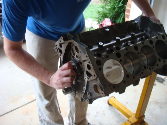
Setting up to install the Extreme Heavy Duty LT4 timing chain set on the block.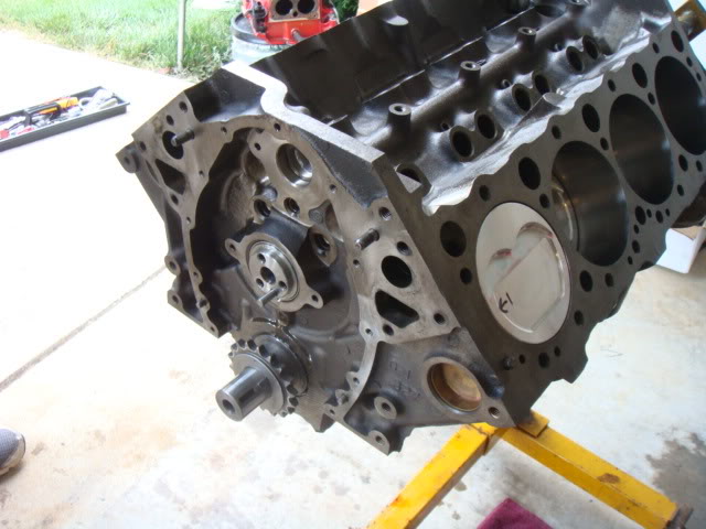
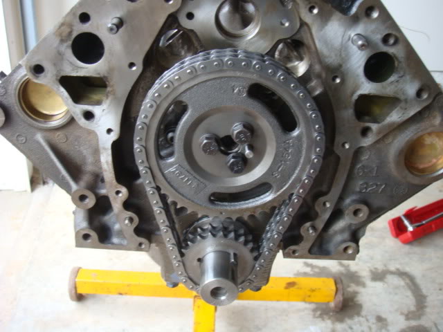
The Extreme Heavy Duty LT4 timing chain set pulled off and discarded as the Cloyes Double Roller replaced it. This is what Will wanted, I wanted to keep the reluctor ring. Due to the amount of slack with the EHD, I totally agreed with the Cloyes.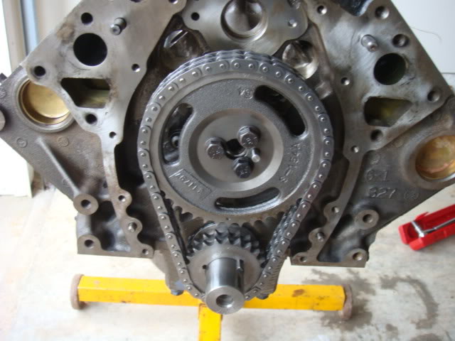
Degree of the camshaft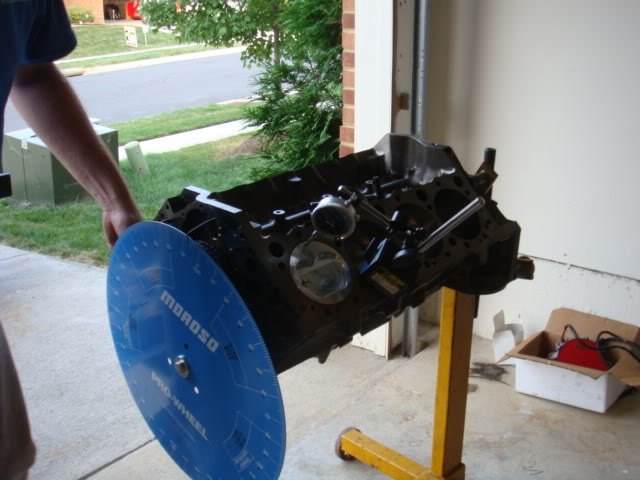
As in everything in the thread, if there are ANY questions I'll do my best to answer, but the heavy hitter is Will. He will comment and post here to get to the specifics on why he chose various things and the direction. I asked him to build me a nice streetable 383, and this is his brainchild. I just bought was he told me to buy!
Once the bottom end was all buttoned up, next came the task of measuring for pushrod length. This was a pain in the butt, because Will had to make a weird Solid Lifter measuring device out of a Hydraulic lifter. It took almost 2 hours to get this thing to act the way he needed it to, in order to make the measurement but here's what he did with it.
Lifterman Device Version 3.0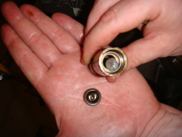
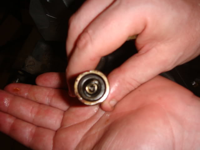
Here's a shot of the Lifterman Device installed next to the Caddy lifter on the right. I'm still not 100% clear, other than he used this setup to measure pushrod length, proper roller rocker angle and piston-to-valve clearance.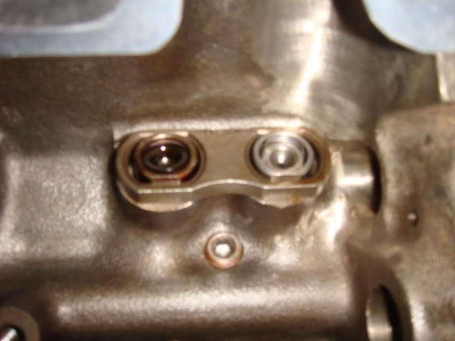
Pushrod measuring tool in place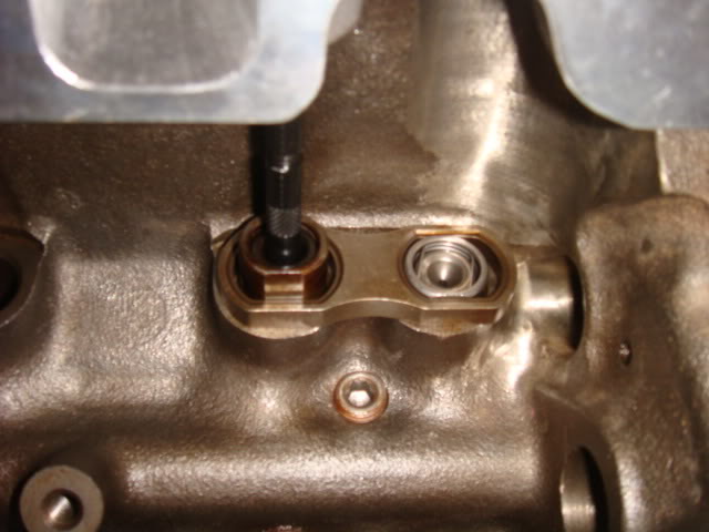
Crane 1.6 Roller Rockers Non-SA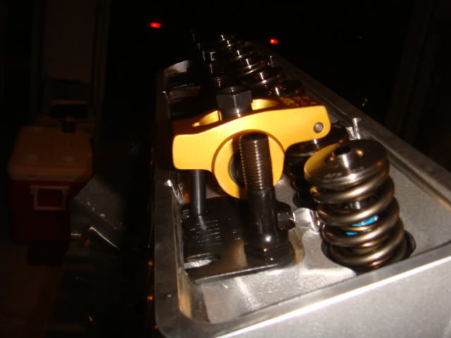
Another View Compressed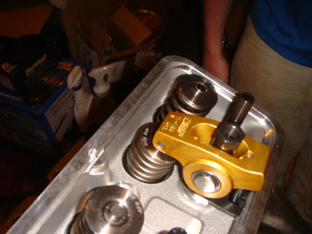
It might be hard to see with the flash but Will used a marker to color the top of the valve, so after the RR made a few deflections on the top of the valve, he could tell the rocker alignment. This may be hard to see due to the flash, but the light wear mark is dead center of the valve stem. Will was very happy with the results.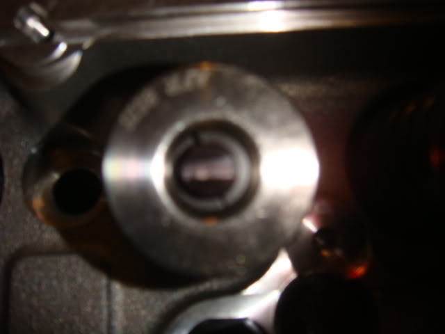
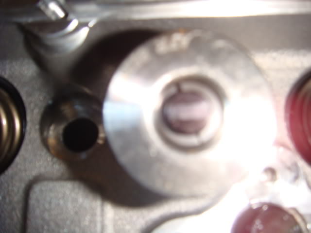
After this was all said and done, Will then carefully removed the measuring tool and determined the final pushrod length for this motor.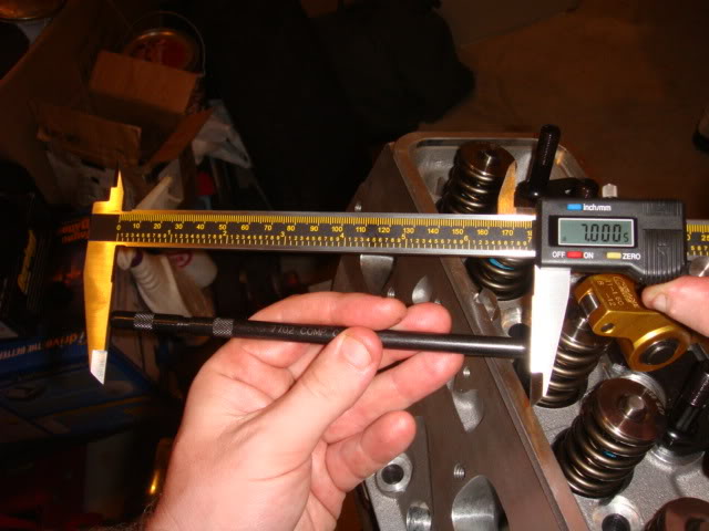
Will had a little Boo-Boo!.........
How Will verified the Piston-to-Valve clearance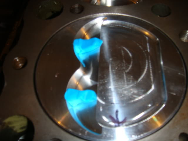
Here's another shot of the putty after the marking, I don't know if you can see it good but that intake valve marking is huge compared to the exhaust valve's marking on the right.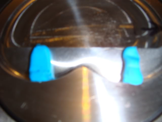
The next thing that Will did was almost get his butt beat trying to install the oil pump pickup on the oil pump.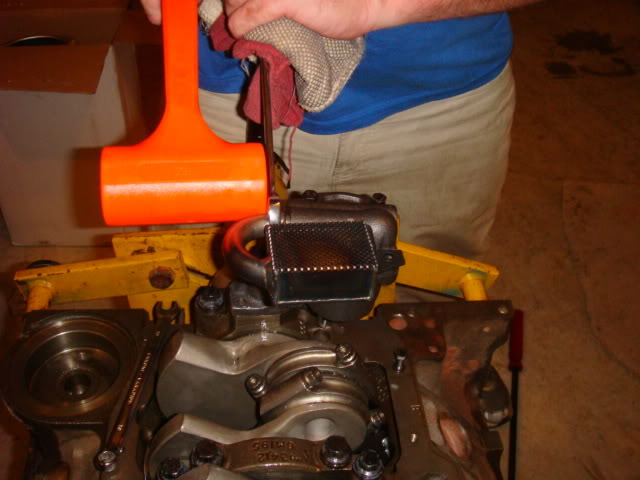
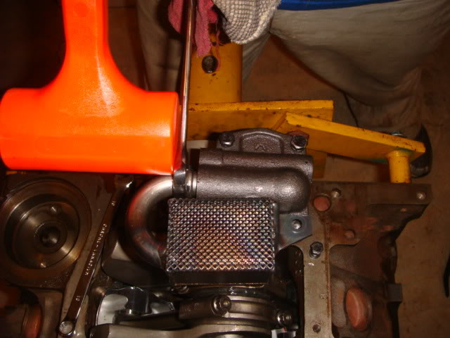
Will won
Next he did this, which is covered up the oil pickup screen, then put a big block of putty on top of the screen.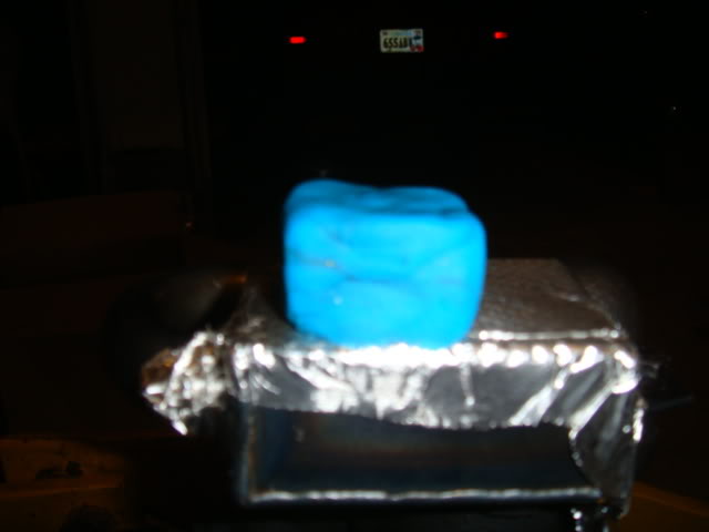
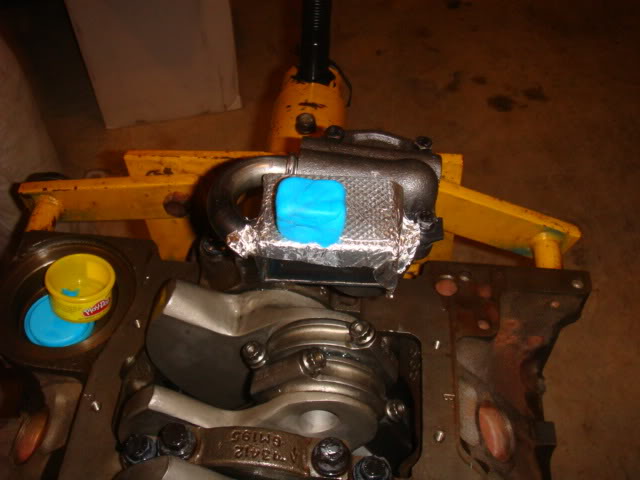
Will then set the Oil pan on the motor, and after pressing it down removed it and verified the crush on the putty.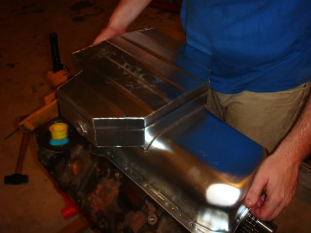
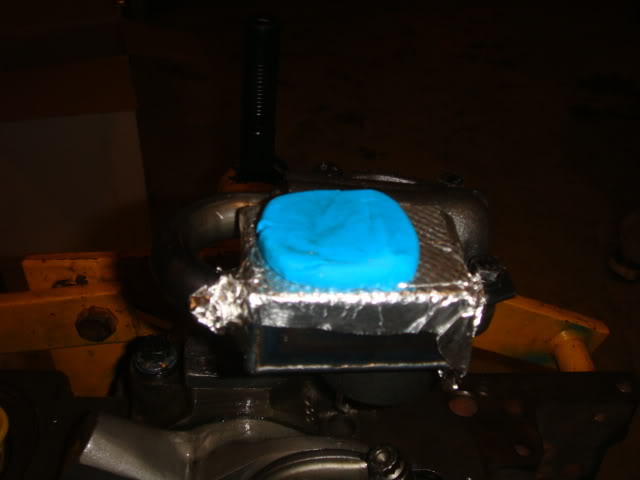
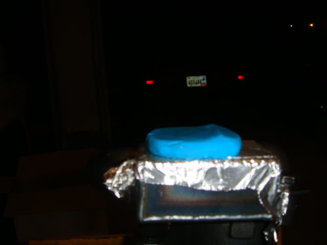
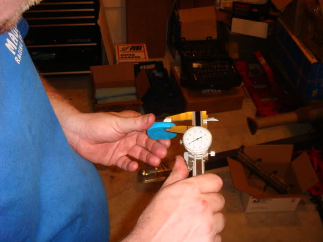
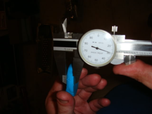
After this measurement, the motor was bagged up. Pushrods will be in this week, and the final assembly should take place next Saturday/Sunday and hopefully back in the car. Thanks for checking out my post!
If the crank gear is the lower sprocket that goes over the snout of the crankshaft, I could use it. PM me a number and paypal address.
Here's a pic with the EHD timing chain gear on the snout.
