You must be logged in to rate content!
111 minute(s) of a 242 minute read
12-31-2020

Compliments of Marktanium @ www.ls1tech.com
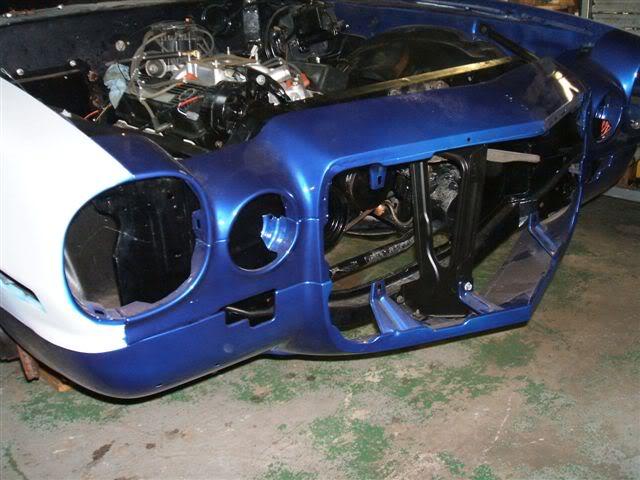
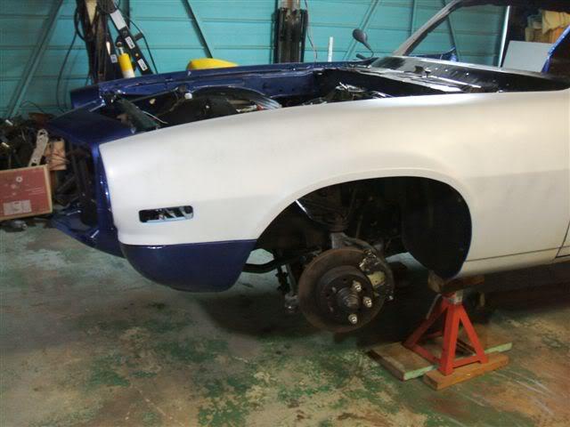
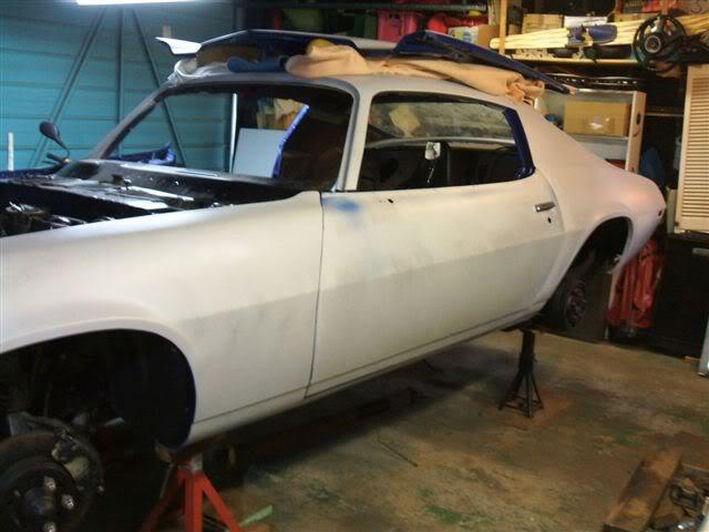
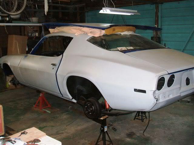
Well, it took me a couple of years to find the car for my build. Then it took me 3 months to find a house with a garage so that we could be together! Now I am putting it together.
The Car: 1971 Camaro RS Z28
After bidding and missing out on numerous cars on ebay, then driving miles and miles to see 'rust free' cars that turn out to be 'metal free', I find an abandoned project on craigslist just 5 blocks from my house. The previous owner had owned it since 1977, and his brother owned it before that.
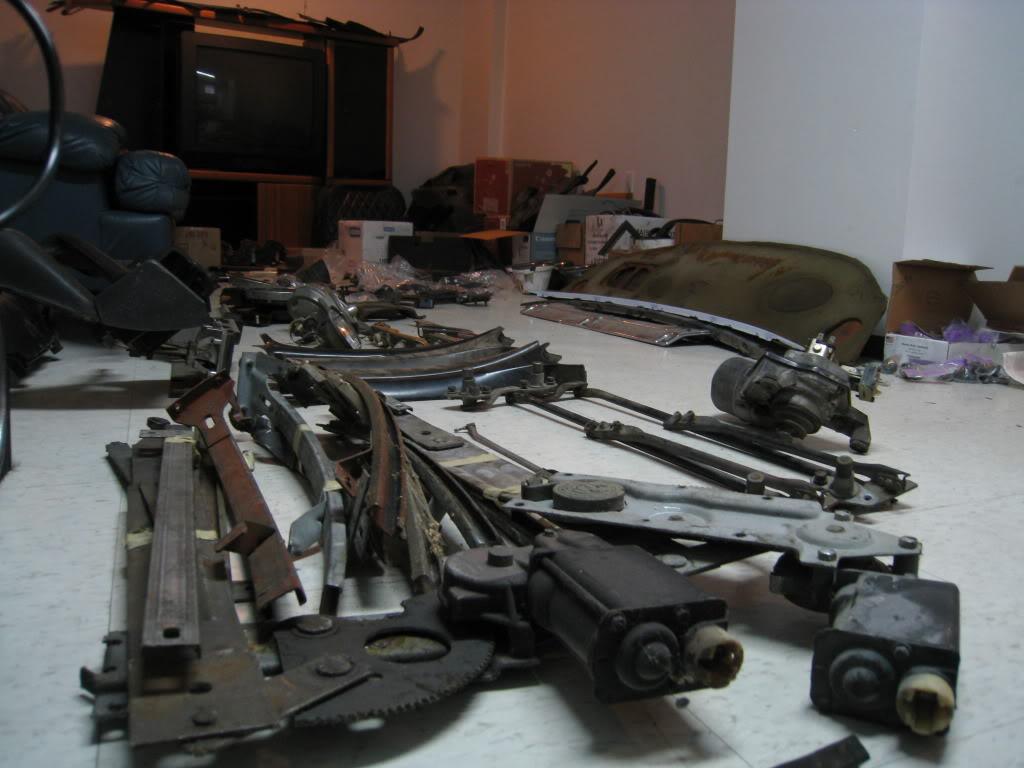
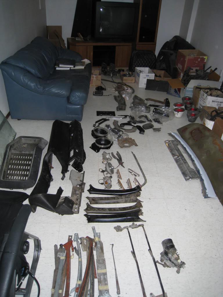
What I got with it: new 327 with a muncie m21 4 speed, all the parts to reassemble it, shy of seats. Car was completely stripped down, blasted, and reassemble with lots of new parts and powdercoating. There is no rust and I got pics of the bodywork in multiple stages to prove it...Nice.
The guy even stored the car for me for 3 months while i looked for a place to put it. Ended up moving to a new house with a garage.
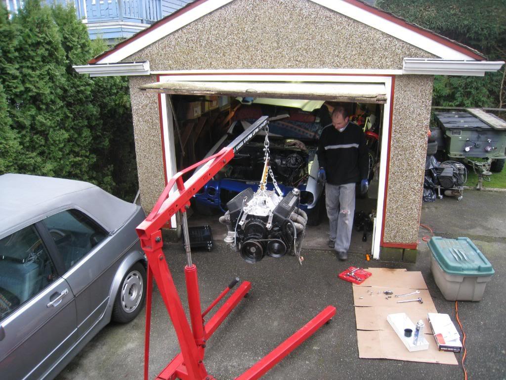
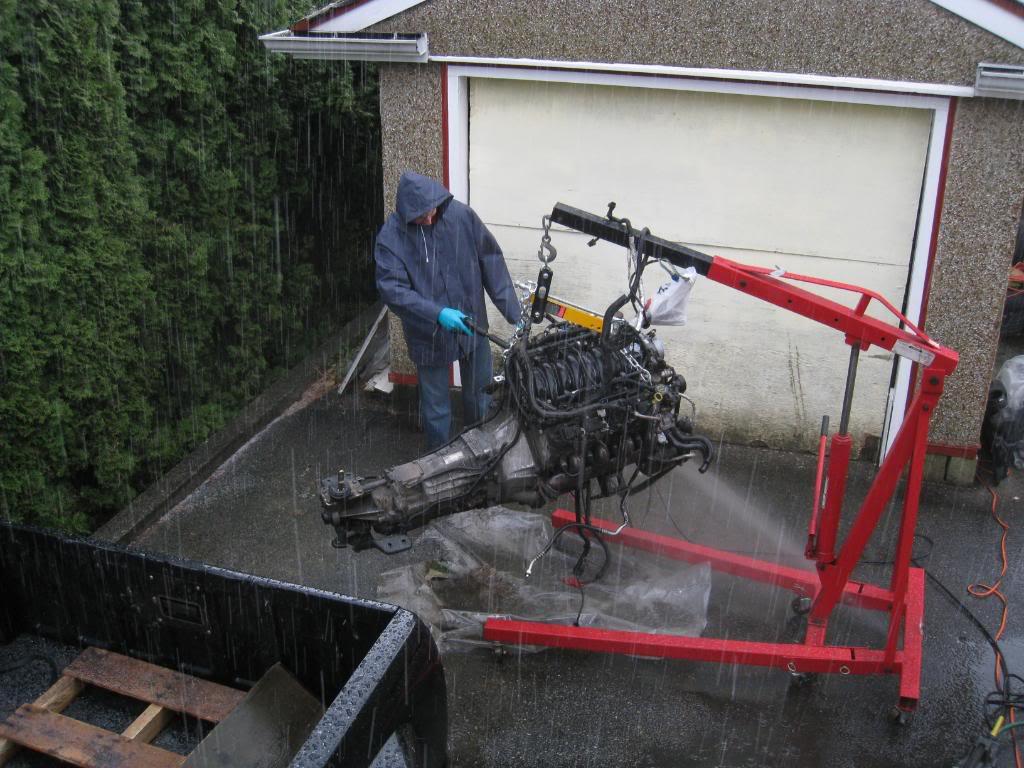
So the first thing I did was pull out the 327/4speed and checked out what was inside it. Turns out the seller was very honest and it was as he said it was. NEW. So I went down to my local hotrod shop, KMS C.A.R. Parts, and did some wheeling and dealing and worked a trade for a complete LS1/6speed out of a 99 TA for my 327/4speed and a core 454/4speed auto that I had from a mid 90's pickup that I parted out.
I figured I would document the build here and I welcome any advice that any of you that have done this or something similar to it have. I will post as many pics as I can, and I am taking pics everyday that I work on it.
Stay Tuned!!!
4/1/2008
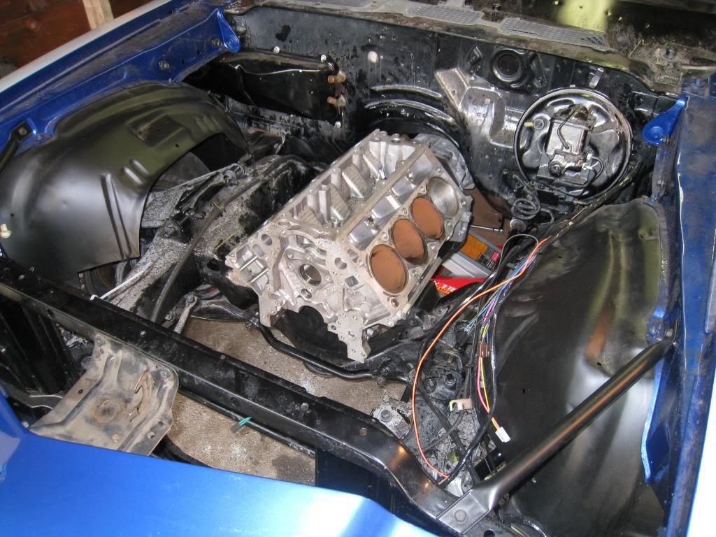
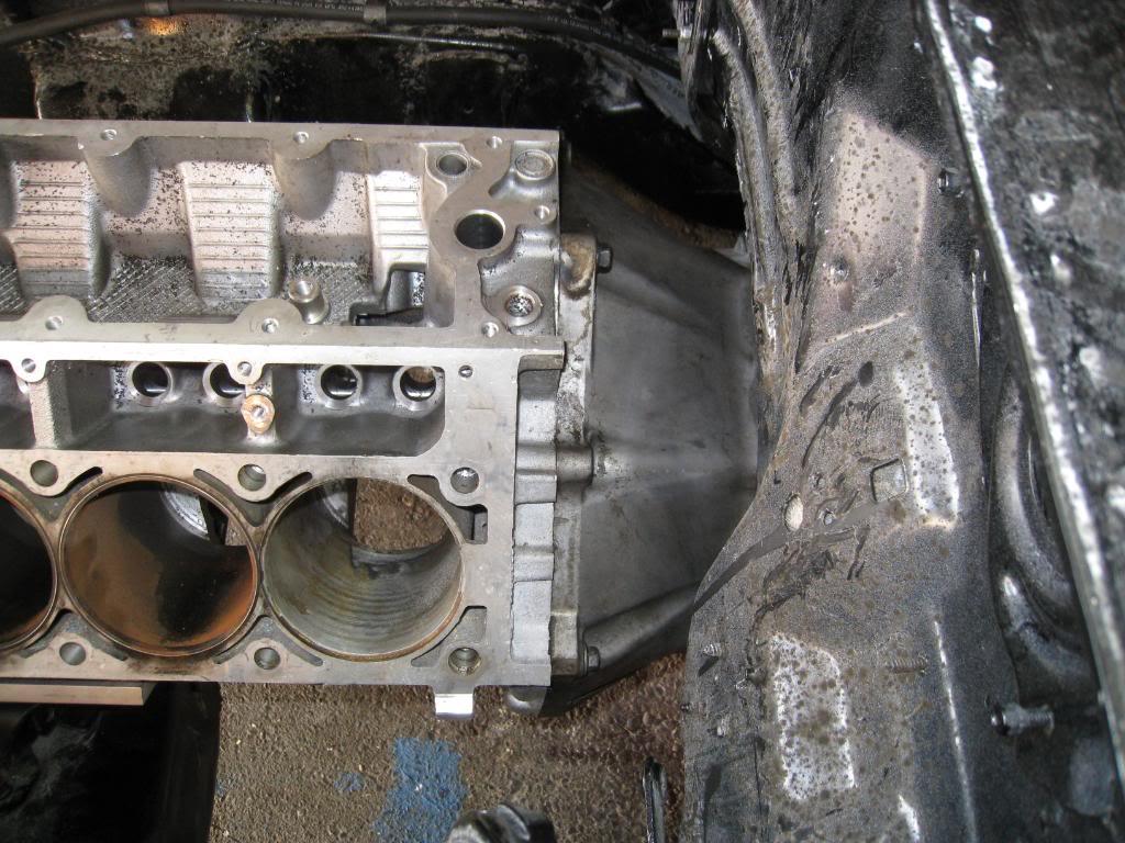
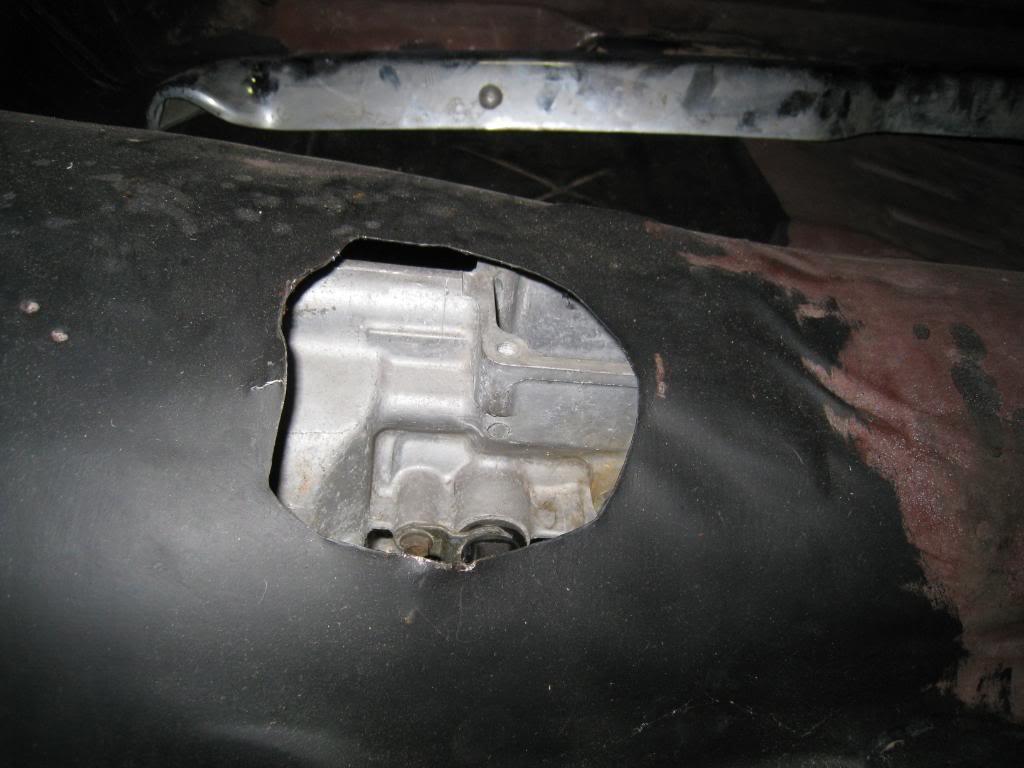
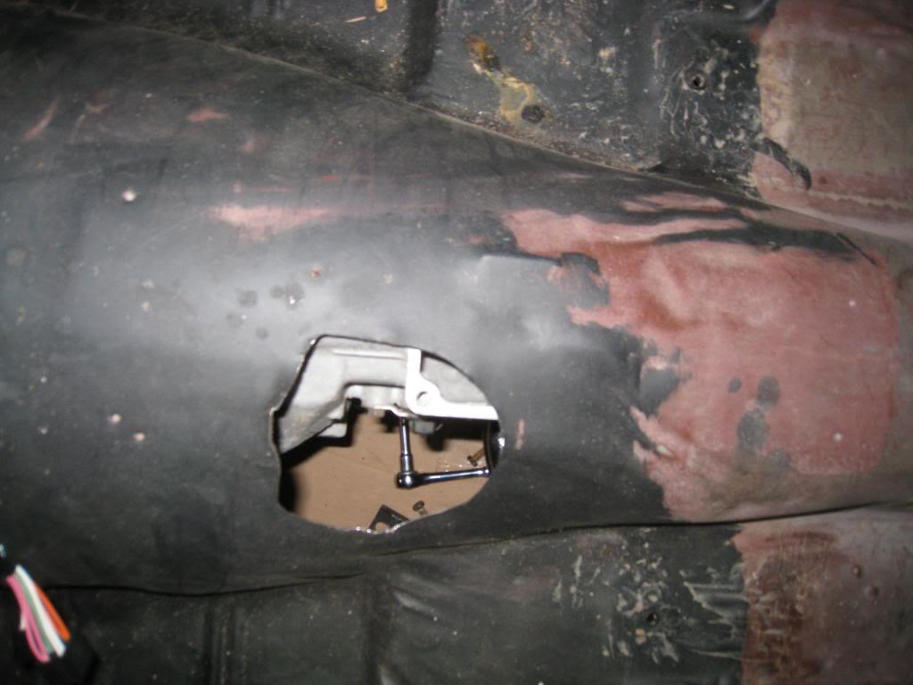
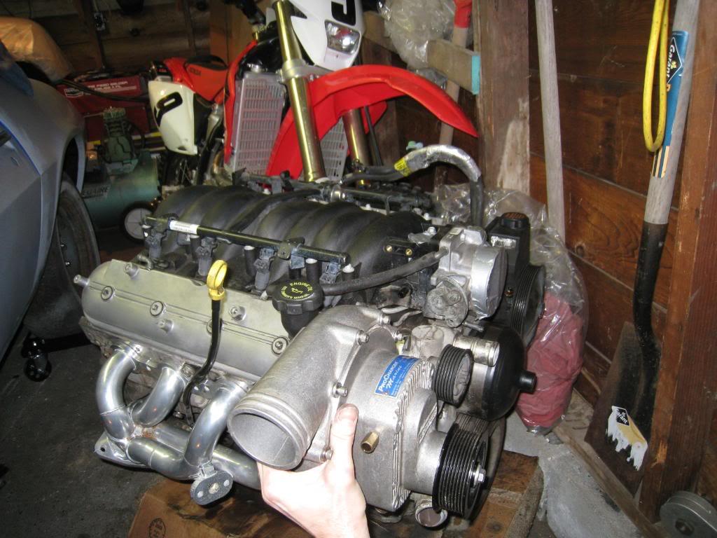
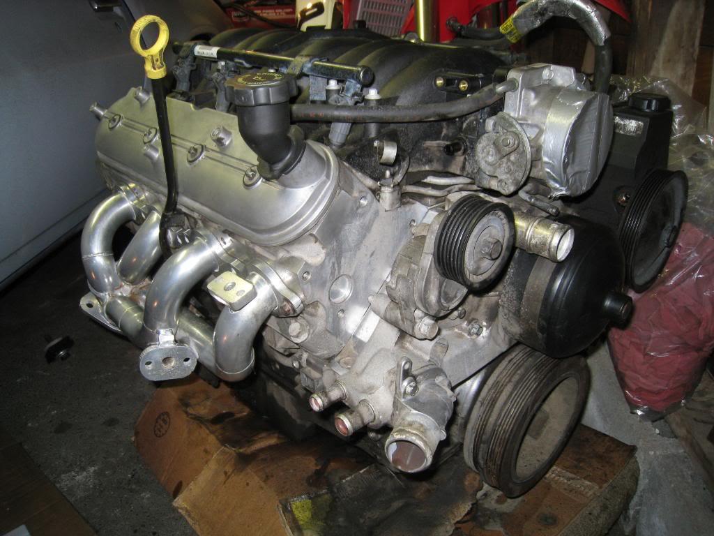
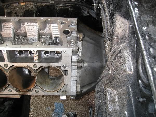
Catching up with my progress. Here's a bunch of pics... got an old LS1 block and trans housing for some mock up. I built my own motor mount plates from a blueprint off of this site, seems to work, although the hole size on the blueprints said 9/16 where they should have been 7/16. I figured that out before I drilled luckily. So here's how it sits, you can see the variance between stock 4 speed shifter hole and where the 6 speed shifter box sits. Will trim that soon. Heres a shot of the motor as it gets cleaner and cleaner. Got these shorty headers out of the local classifieds for 200 bucks, and am considering my own custom install of a Procharger that I removed from a boat I used to own. Thats it for today...
4/5/2008
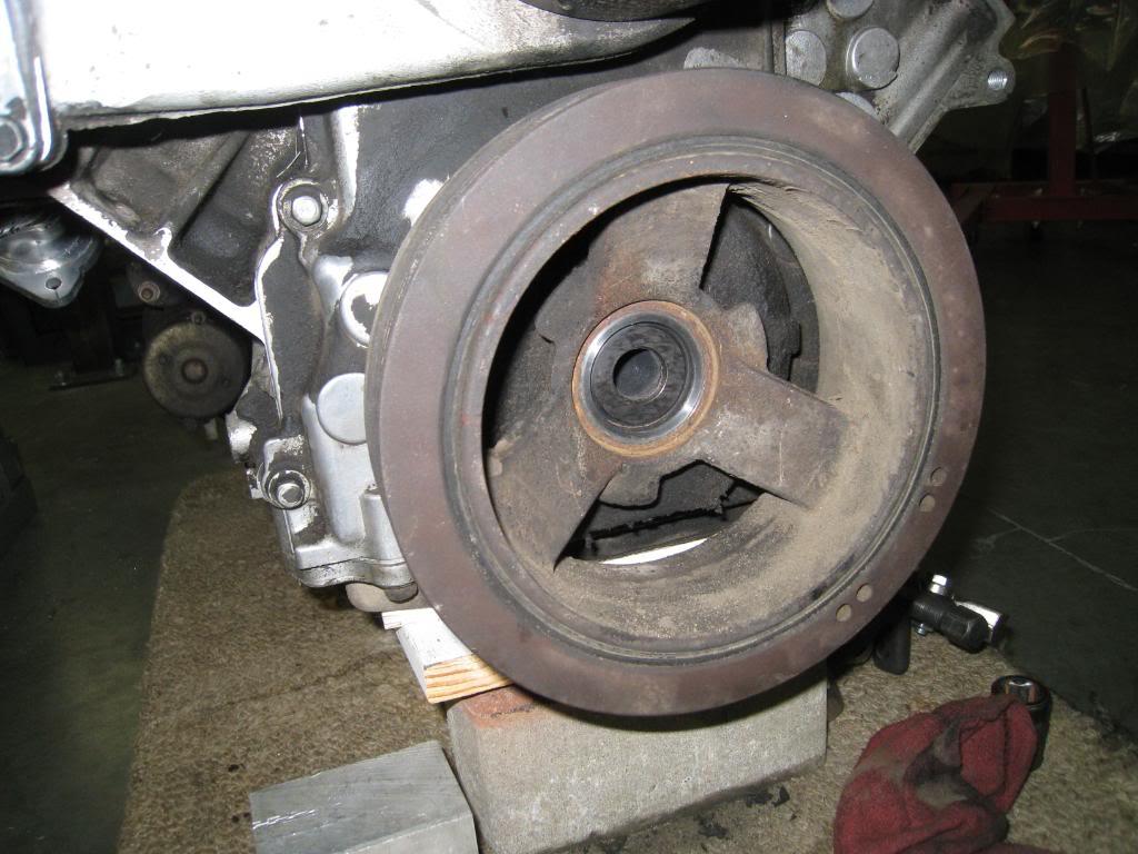
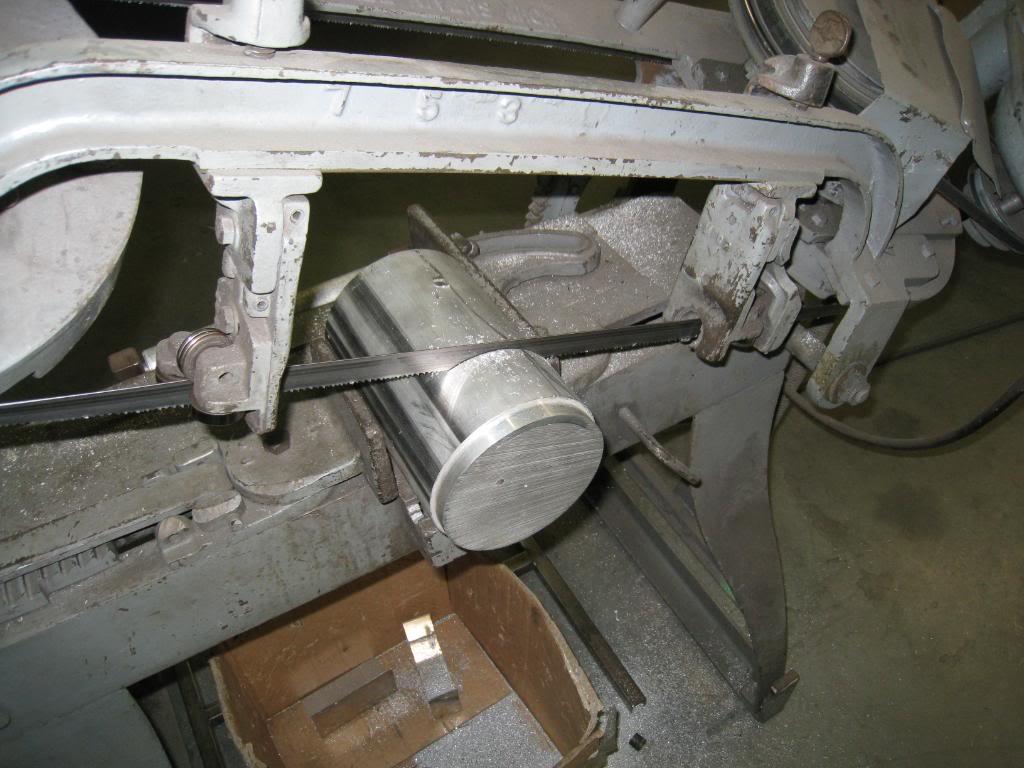
Took the day off of work and went over to a friends shop, Momentum Auto Parts, to use the lathe! Since I am doing a fully custom Procharging on this motor I have to fabricate everything. So I started with this 5 inch chunk of 6061 and made this crank pulley adapter. The plan is to mount the charger on the passenger side of the engine, just over the stockserpentine belt tensioner and a little outboard.
I took a boroscope to the LS1 I got and checked out the cylinders and found that this motor needs a rebuild. No big deal, as Richard from the shop I got it from, KMS C.A.R Parts, told me to feel free to tear it down and if it needed work to bring it back and they would get me another one. Almost thought service like that was dead...
That was a full days work....whew... only 28,000 more parts to fab, assemble, etc., till I'm done!
Here's a cool motor thats for a buddy's PT Cruiser...I know,I know,...anyway, rumored to be 750hp...
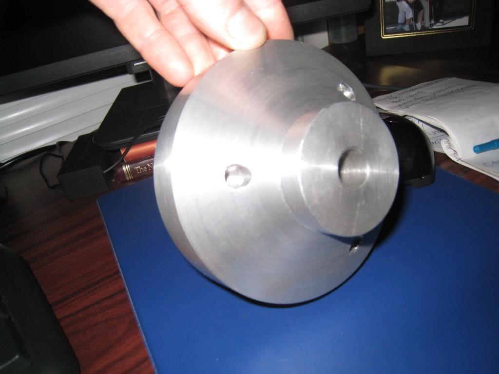
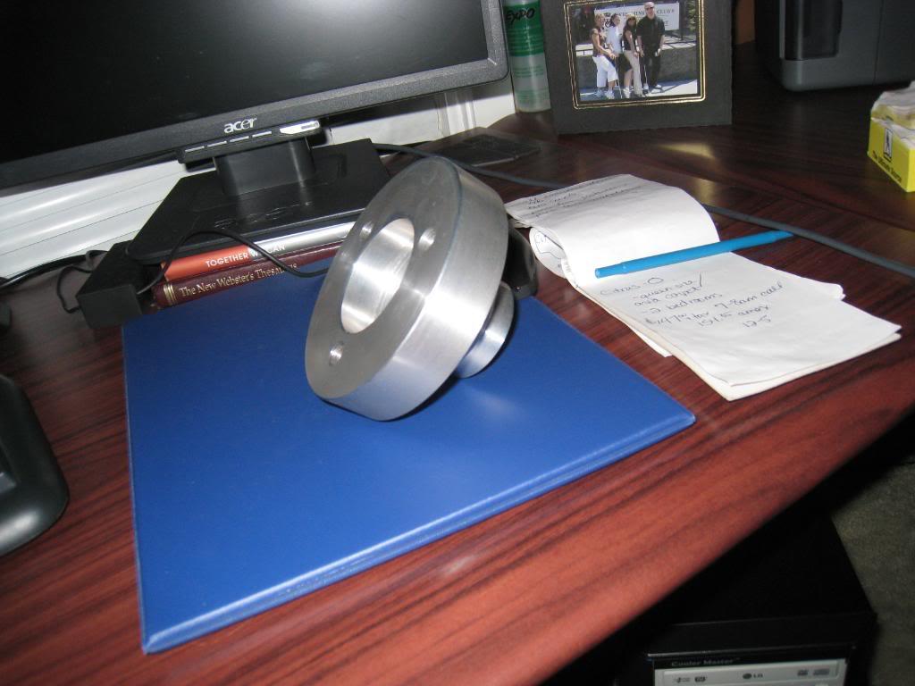
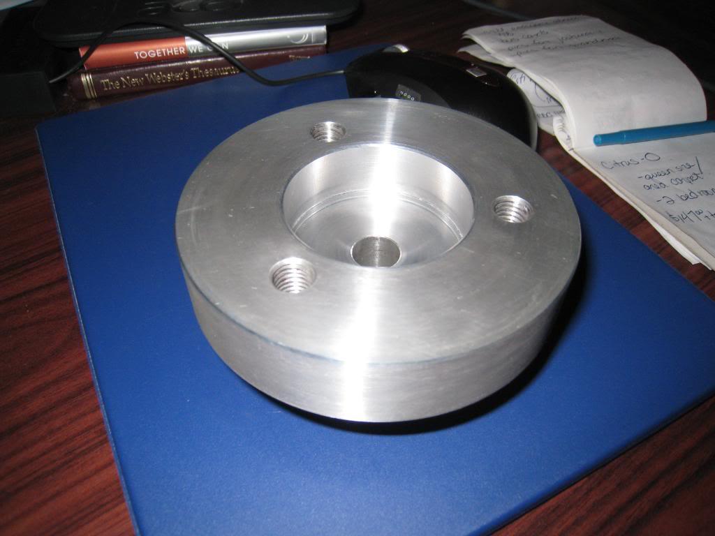
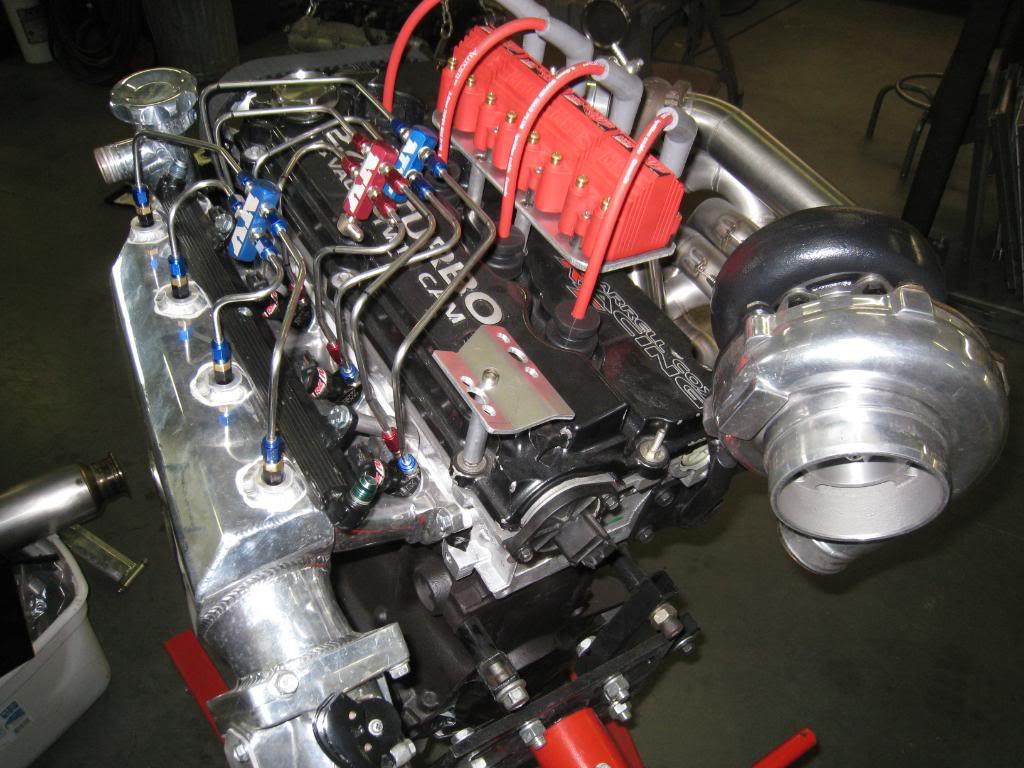
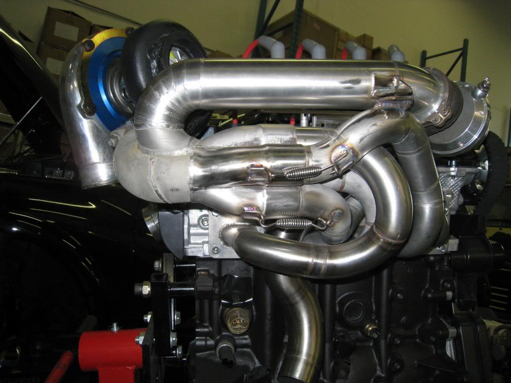
4/8/2008
No real progress to report, have to do responsible things too it seems. Did get a couple of new parts though... Here's the oil pan GM # 12614821 ($256cdn) also got the dipstick # 12603506 ($24cdn), and the oil pickup (gm calls it a screen) GM # 12608593 ($57). Still waiting on the windage tray and dipstick tube.
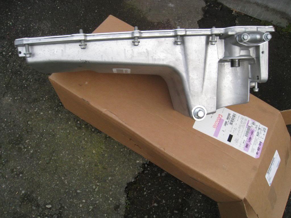
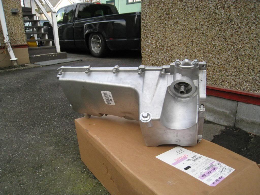
I'm keeping the fuel injection. I am going to fab up my own pump system using 2 walbro 255's in tank run in parrallel. I think the fuel system will be fairly straight forward, being that I am procharging it and am using a rising rate fuel pressure regulator and return system. It's all custom on my car anyway, so I figured with enough research I should be able to make a pretty simple system.
And yes, there are alot of different opinions of what rust free is out there....
I went with the H3 pan as I want the engine as low and far back as possible. I must admit I didn't even try the f body pan, but when I put the dummy motor in without a pan on it, it looked like it would be too close. In saying that I also noted that there is a lot of space at the back of the engine, and maybe the f body pan would work if the engine was mounted in relation to the pan.
I'm going to go visit Art Morrison's shop at the end of the month to look at his front clips, may have a new front end in my future...
4/12/2008
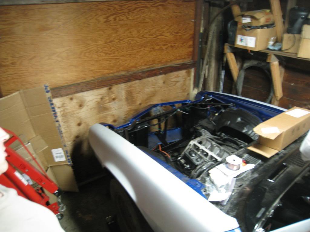
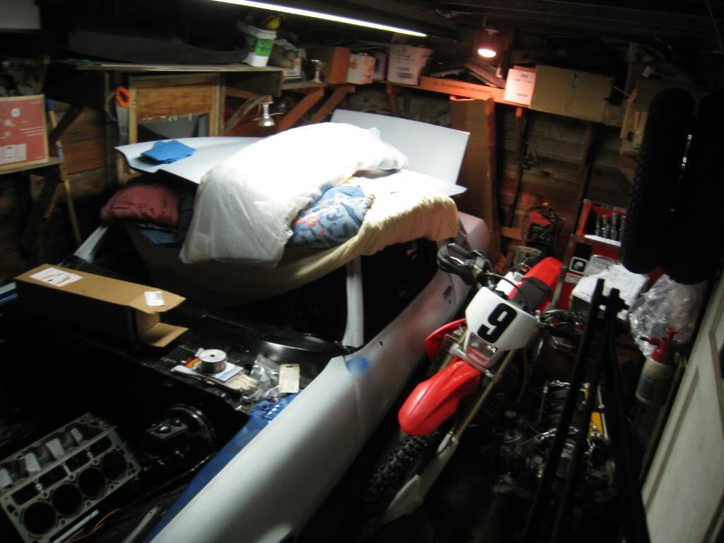
ow big is my garage???
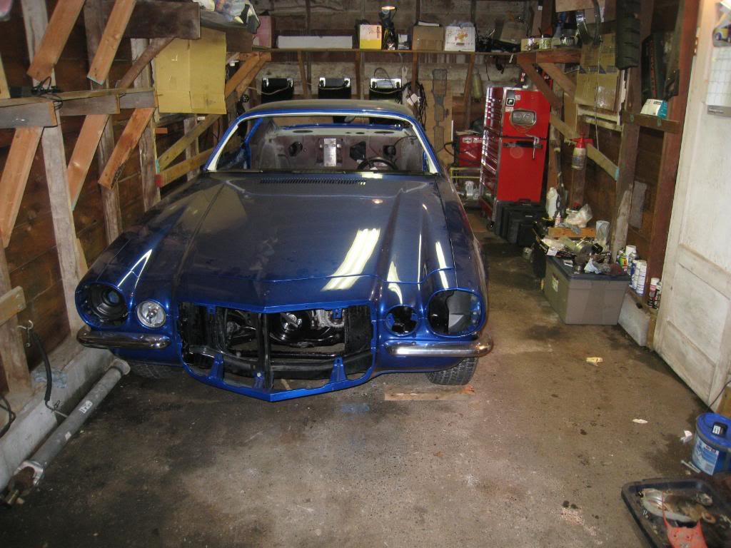
Well, lets put it this way, I may qualify for the smallest garage ever for a project of this size to be done in.
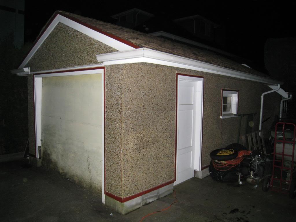
My garage is 10' x 19'. In order to work in it I have to drag out the engine, 2 motorcycles, my tool box (recently brought home, quit my job as a motorcycle tech as it was cutting into my time to build this car...jk), and an engine hoist. The car is on 4 wheel dollies so I can move it around...Yes, I am dedicated and patient.
Ryan, who did your paint? I am in need of a trustworthy bodyman / painter. I'd love to check out your car sometime, PM me when you get a chance.
Here's a few pics of my MASSIVE GARAGE...
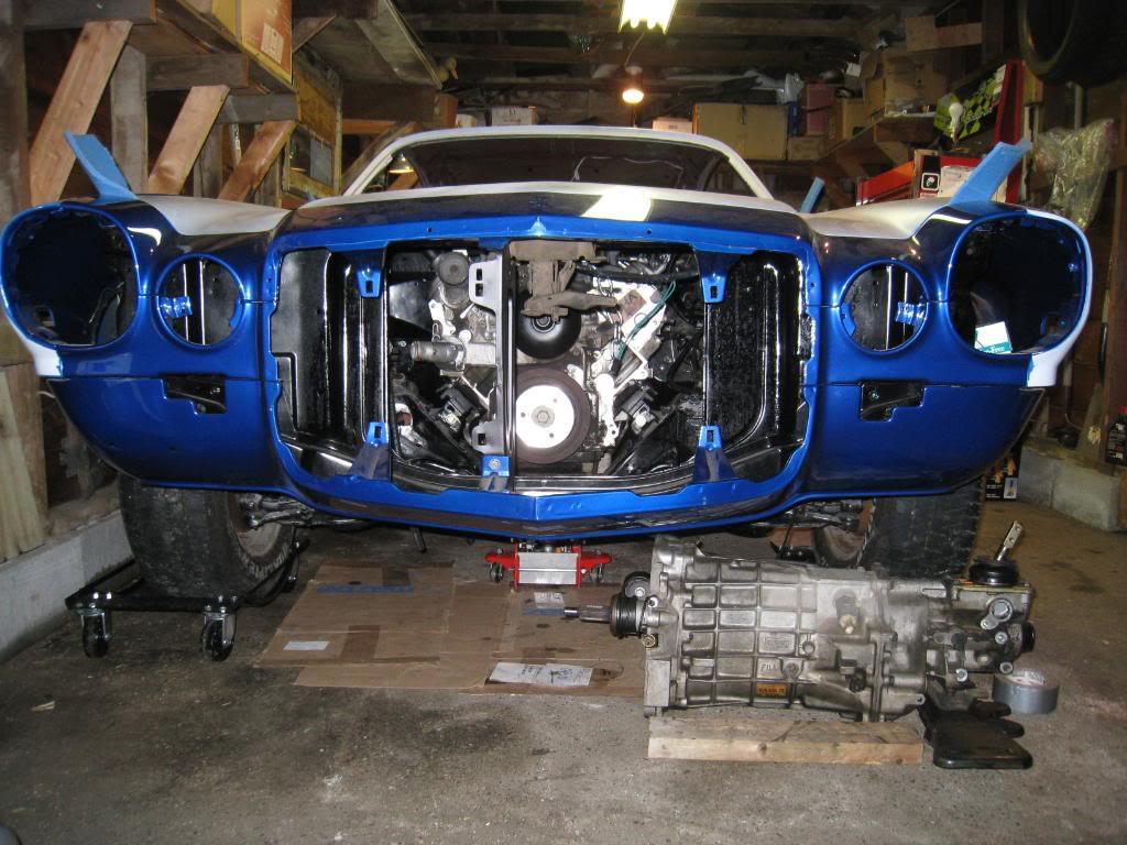
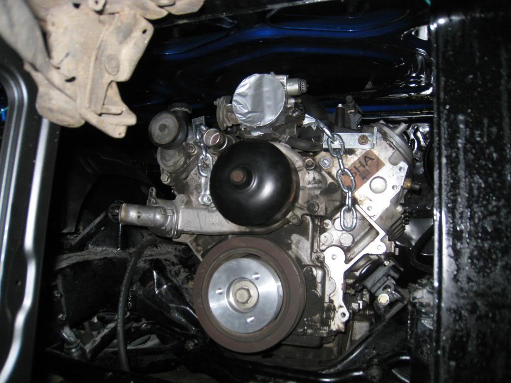
The LH8 pan hung down about 2 inches, however, that was using the transdapt style motor mount adapter plates and no shims. I wanted to get the motor as low as possible for handling reasons, and when I did I saw how low the pan was and decided it was not the way to go. I want the pan to be no lower than the cross member. I also noted that the front of the LH8 pan is deeper than the F body pan, and hits the stock steering. I swapped the pan back to the F body pan as it has a more shallow front edge, and found that it was level with the crossmember, but also between 1/4 inch from touching it and just touching it on one corner. I figured that a little crossmember massaging will take care of that gap. I then realized that I hadn't taken into account that the alternator sits very low on the drivers side. I put it on and found that I couldn't steer. Damn. Ended up lifting the motor maybe 1 inch and all woes are cured, except the pan to crossmember clearance, but again, thats a couple minutes with a grinder and reweld the seam.
If I went to a rack and pinion front clip it would all be perfect, but for now, I can adjust motor mounts...
The headers are for a 99 camaro, they are JBA manifold replacement type. (pic in an earlier post) I know they aren't the best choice, but they were cheap and I have aspirations of a twin turbo set-up...
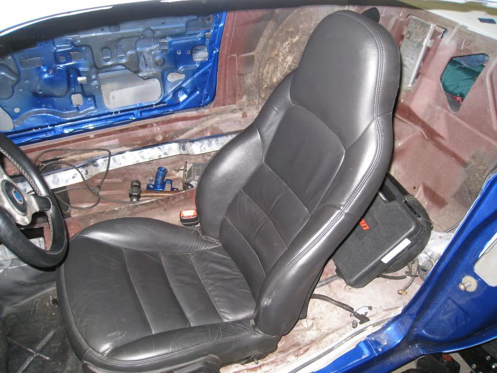
Here's a couple of pics... '07 Corvette seat, note the hood to throttle body clearance, thats with the motor jacked up to the height it needs to be.
5/13/2008
Peter, with the engine at a usable height, alternator and steering wise, there is roughly 2 inches between the throttle body and the hood, (stock hood) I think the brp mounts are even higher, from the looks of the pics anyway. There is lots of room at the back of the motor, but to move it back would cause issues with the shifter placement, plus the space between accesories and upper control arms. I am mounting my pro charger on the passenger side outboard of the stock belt tensioner, and am trying to keep it as low as possible, (no higher than the oil filler cap on the valve cover). I am currently using the stock booster, but plan on going to a hydro boost.
5/19/2008
OK, so the LH8 pan was not ideal for my car. I posted it on craigslist and sold it the next day at only a $55 loss. The issue I had was steering interference. The LH8 pan may have worked if I jacked the motor up high enough, but the hood to throttle body clearance would have been limited. If you are following this thread then you know of my plans to pro-charge. This being said, I need all the space I can get to squeeze the charger under a stock hood.
SO...the mount set-up that works for me. I am using the trans-dapt ls1/sbc adapter plates, with a 1/2 inch spacer placed under the factory crossmember to mount plate. I am re-drilling the crossmember and shifting the mount rearward 1/4 to 1/2 inch. This allows good clearance for my F-body oil pan, steering , and alternator.
The LH8 Pan was better at the rear of the crossmember, but the sump sat lower than the crossmember (as low as 2" before jacking up the motor) and the front of the pan was deeper than the Fbody pan and hit the steering before being jacked up, and at that point I decided to use the F body pan as ground clearance is a big issue for me.
In conclusion, I recommend the F body pan. ( mine is from a '99 trans am )
7/5/2008
Well, I finally found someone to finish painting the car! Waiting for the flat deck right now to take it to his shop. After a bunch of research and emails, I got a hold of the guy who started the bodywork in the first place, and with a little begging, he decided to bench another project he was working on to complete mine! Yay.... continued....
10/29/2008
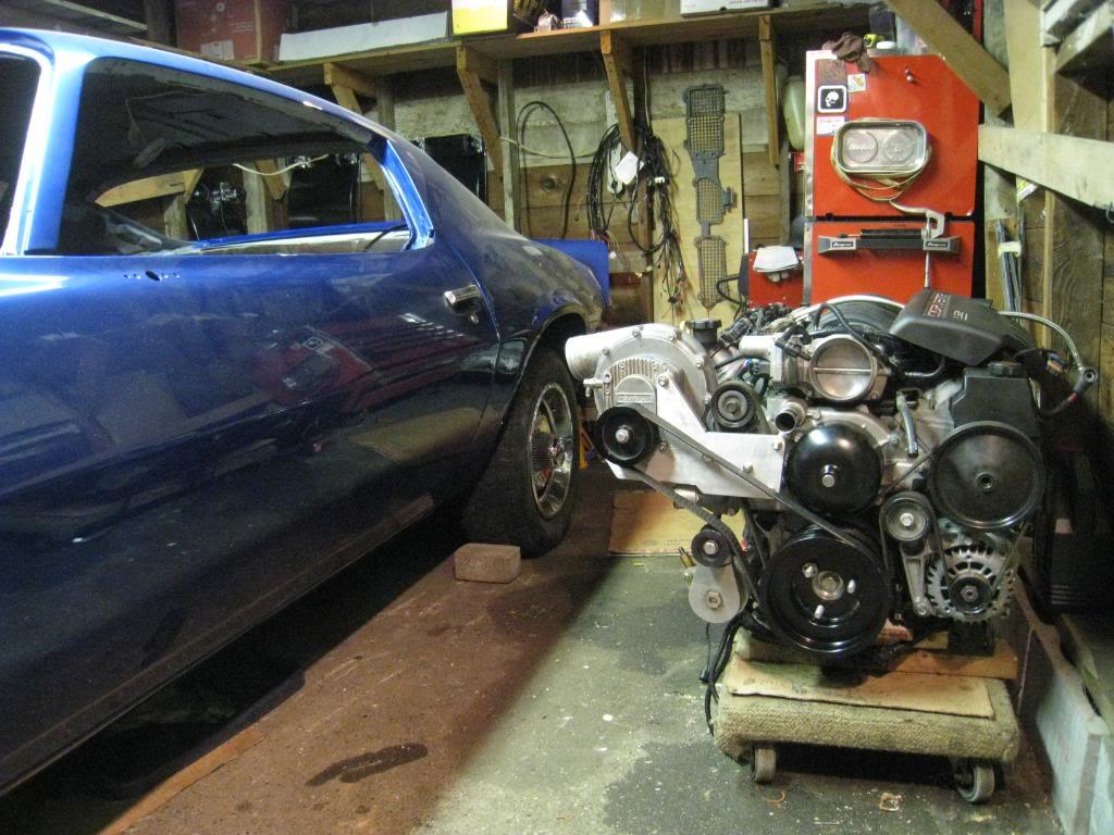
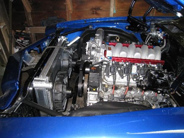
things are coming together ever so slowly.... anyway, here's a pic! built my own procharger mount kit, and as you can see the car is fully painted!
12/13/2008
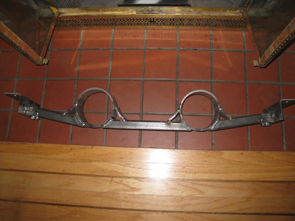
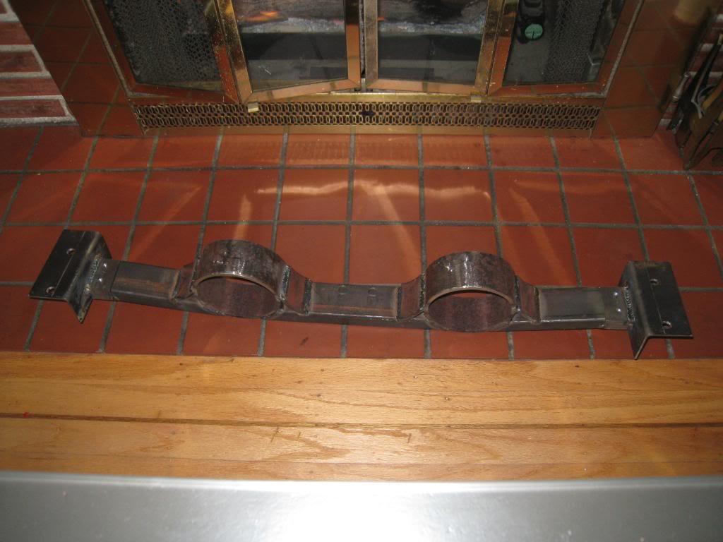
Here'e my transmission crossmember. it's a 3 piece deal, took way too long to build, but thats the fun part, right?
2/18/2009
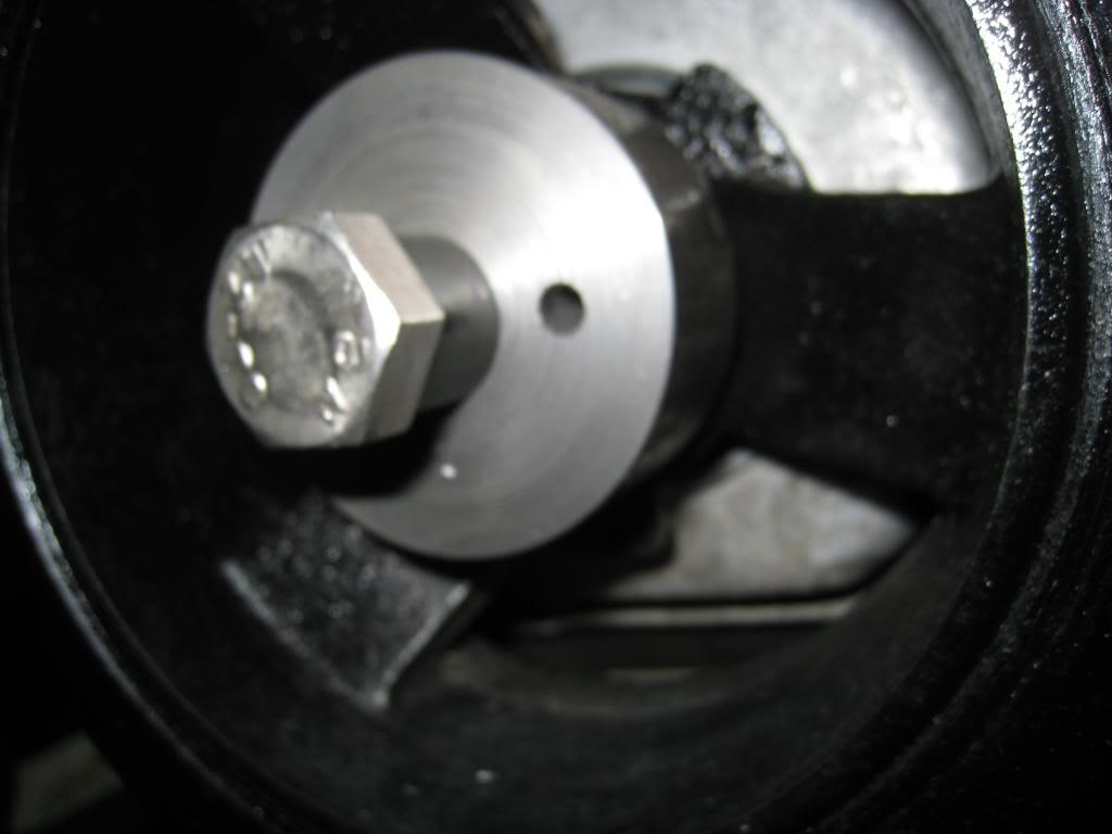
Since I am supercharging I had to 'pin' my harmonic balancer. Here's how that went.
1. Took a chunk of tool steel and 'spun up' a guide tool on a friends lathe.
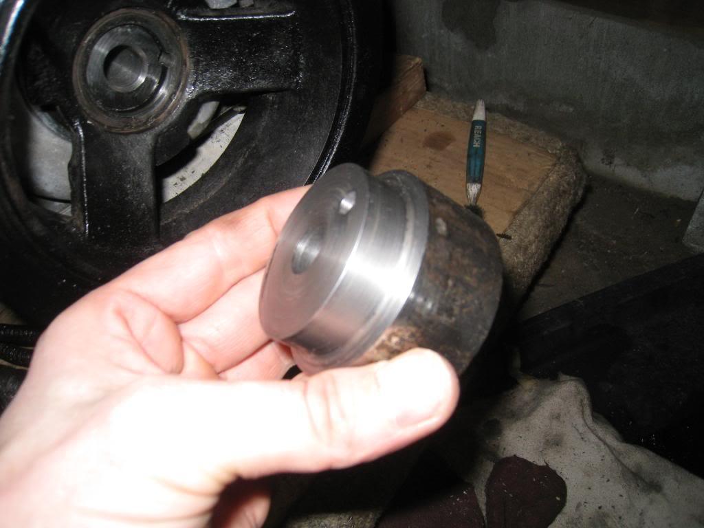
2. Bolted it to the balancer.
3. Took a brand new 1/4" drill bit and marked off with tape 5/8" depth.
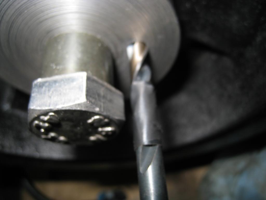
4. Drilled to depth, then removed Tool.
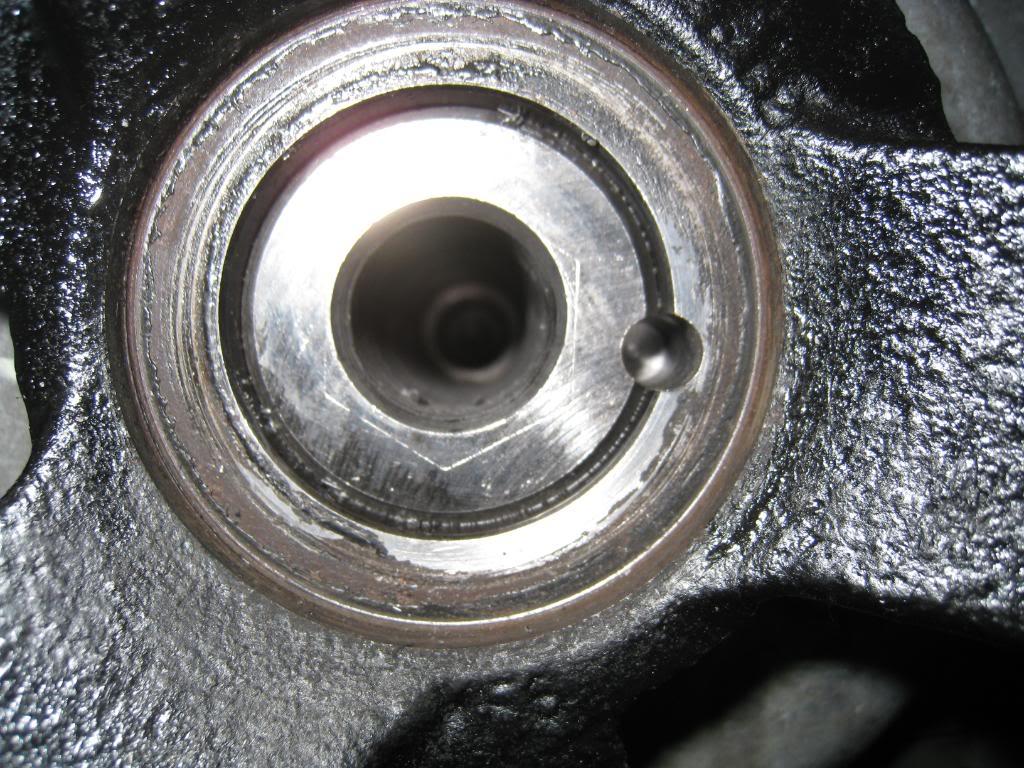
5. Cut 1/2" off of the chuck end of the 1/4" drill bit.
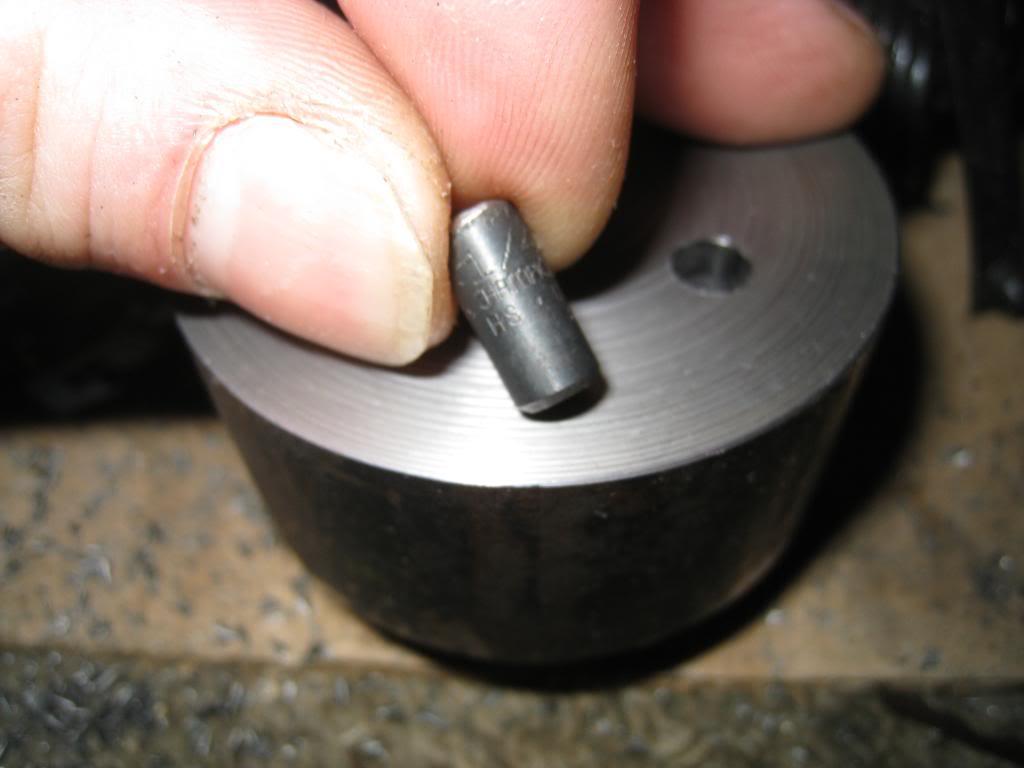
6. Inserted 1/2" drill bit piece into crank pin hole.
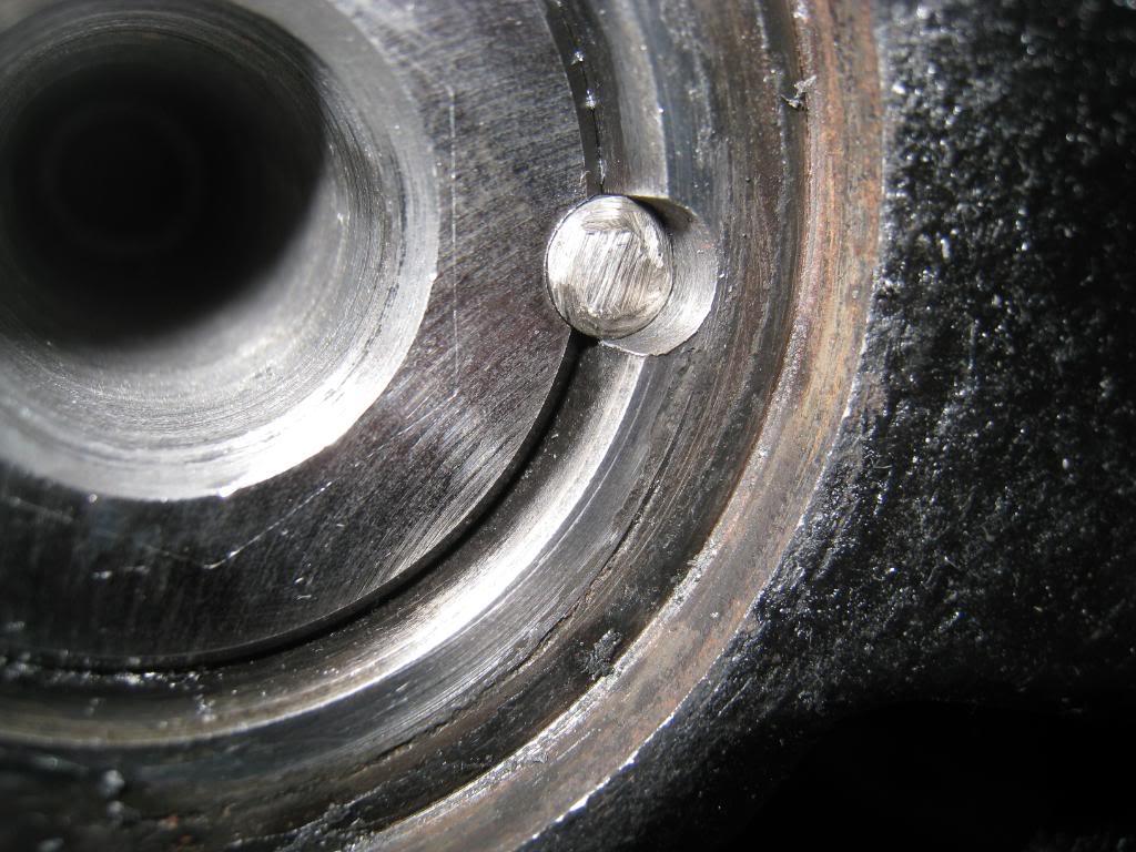
7. Re-assemble and enjoy!
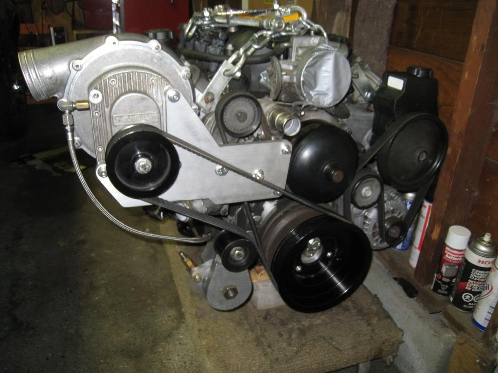
The whole point of doing a project car is building it. I'm not rich either, so alot of it comes down to if I don't build it I can't buy it. Well, really, lets put it this way, if I could afford to buy the trick parts, I probably would. Until I win the Lotto, this is it. (Even if I was rich, I would still make my parts, only I wouldn't have a pesky day job to get in the way!)
2/22/2009
GOT IT IN!
Hopefully this isn't another test fitting! Got the LS2 into it's mount and all bolted up. It's a tight fit, especially between the 'charger and the upper control arm. But there is space. Time to start the plumbing.
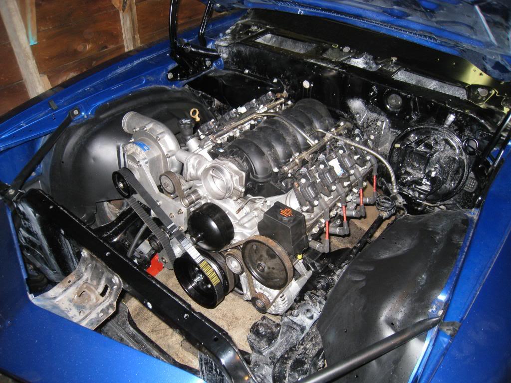
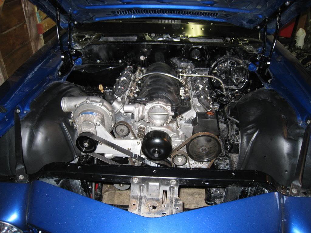
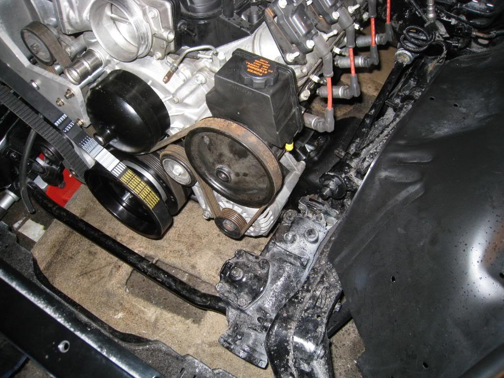
3/3/2009
Cleaned up the tranny a bit and installed it tonight. The new crossmember worked perfectly, really happy about that! Here's a few pics. Note the clearance between the hood and intake, that shot is with the hood closed!
- all this is being done in a 10 x 20 garage too!!!

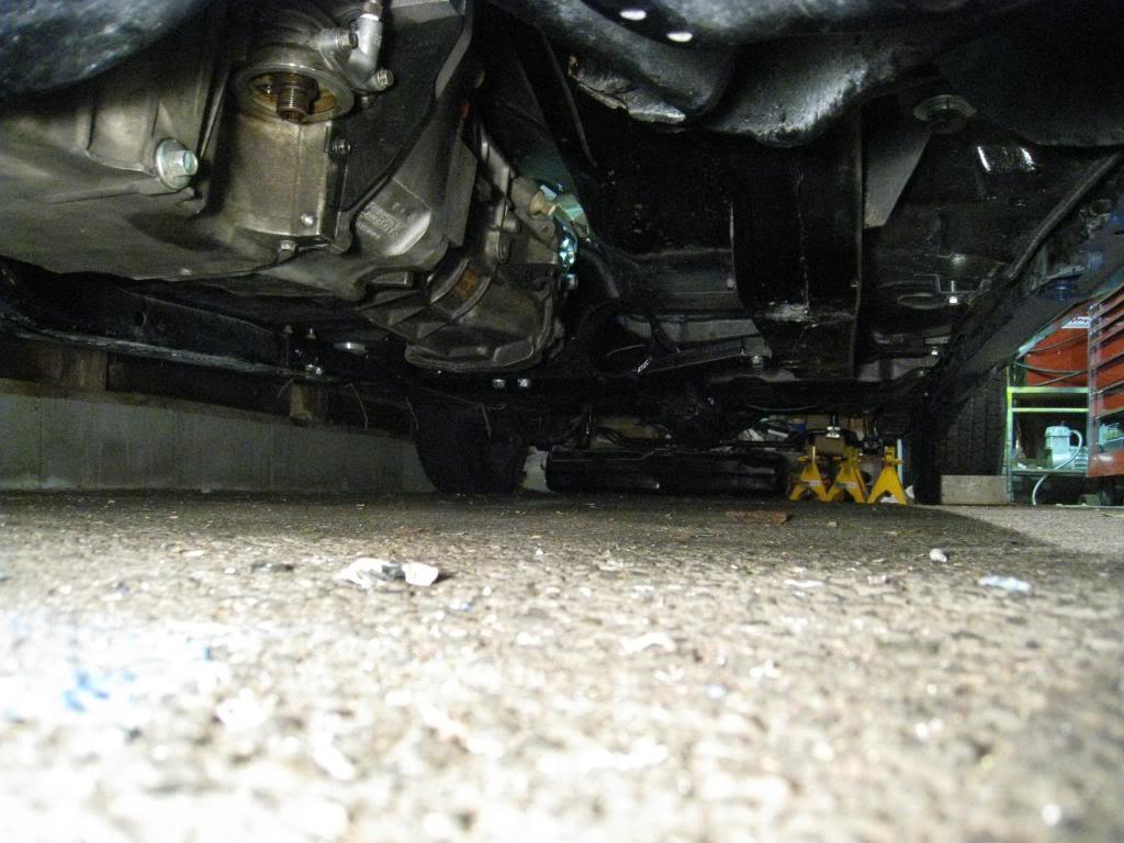
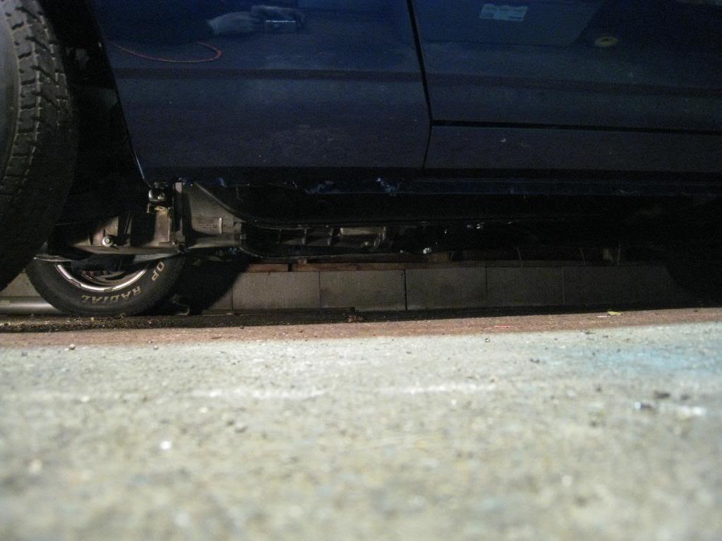
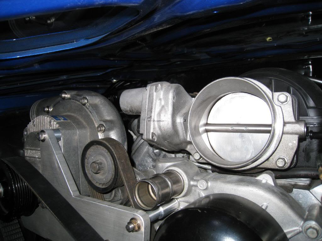
3/8/2009
Ok, I've been putting this daunting task off as long as I could. Time to convert my engine harness so that I can get this thing running.
Step 1. Collect as much information as possible. I found a wiring diagram/manual online and downloaded and printed as much of it off as I thought neccessary. Also found a manual for an aftermarket harness so that I could see what is used after all is said and done.
http://www.ls2.com/forums/showthread...hreadid=405808
http://www.hotrodlane.cc/PDFFILES/squireLS7.pdf
Step 2. Lay out the harness on the livingroom floor (sorry Jenn)
Step 3. Label as much of it as possible. I went as far as to use the aftermarket instruction sheet and use their item numbers on the labels, thinking that at the end of this it will make more sense.
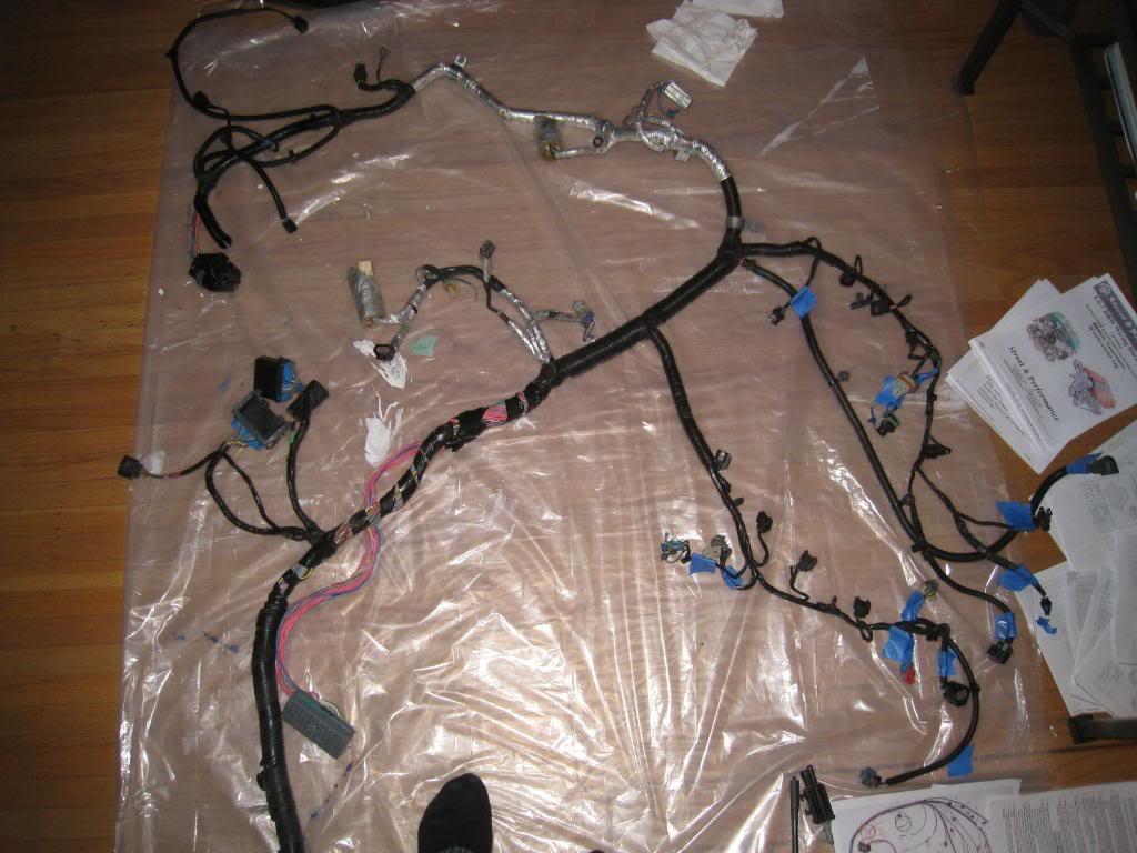
3/11/2009
Again drifitng away from my wiring... At least I got something done!
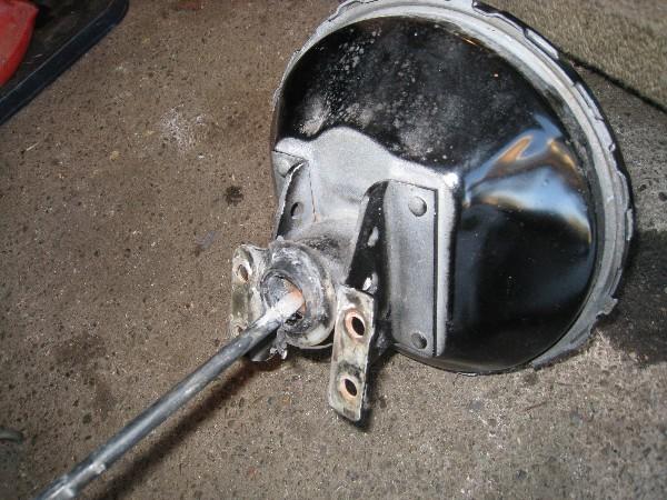
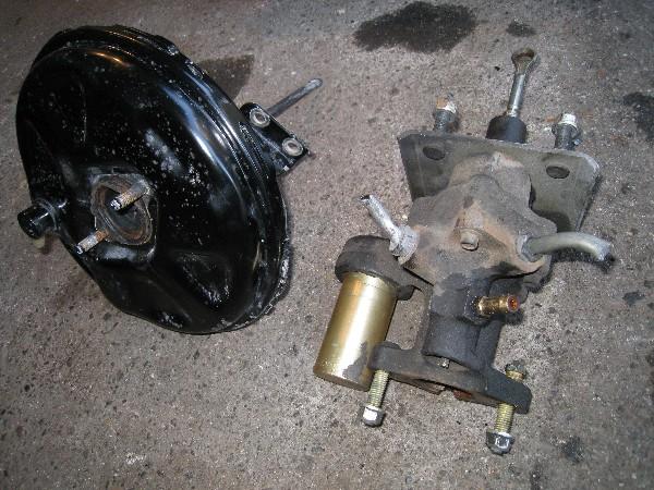
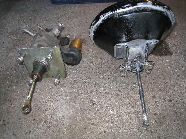
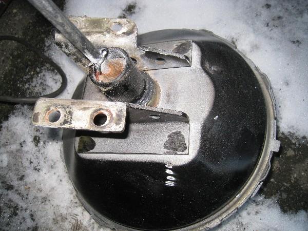
Here's a cheap way to replace your Vaccuum Brake Booster with a Hydro-Boost booster. Or at least thats what I am hoping.
So I want to use hydro-boost power brakes so I don't need to be concerned with a lack of vaccuum because of my engine being super-charged. Not only that, the Hydro-Boost just seems to me to be a better idea.
I could have bought an aftermarket kit for $$$ but I'm all about building it myself, so here's what I have found.
I found that Astro / Safari vans run a hydro boost system, that looks very similar to the aftermarket systems. I went to the wrecker, did some snooping, and found that pre-95 boosters have a flat mounting flange on them. The newer ones are recessed into the firewall on an angle, which may have worked if the bracket was flipped around, but I felt that the flat bracket would give me more options in case I had to fab something up. Paid $45 for it.
Took the master cylinder and vaccuum booster off of my car and started thinking.
Here's what I did.
Step 1. Remove booster bracket from booster by grinding off rivet heads and prying off.
Step 2. Using a die grinder, elongate the rivet holes towards the center of the bracket by 1/4 inch.
Step 3. Loosely attach the brackets to the new booster and cut the excess stud off.
Step 4. Bolt the assembly back onto the firewall and then tighten the bracket to booster bolts. This will assure that the brackets are positioned properly.
Step 5. Re-attach the master cylinder.
Thats all I had time to do so far, here's some pics...
I'm looking into a different master cylinder, I'm not happy with the hood to cylinder clearance. I'll address the pushrod length and plumbing later.
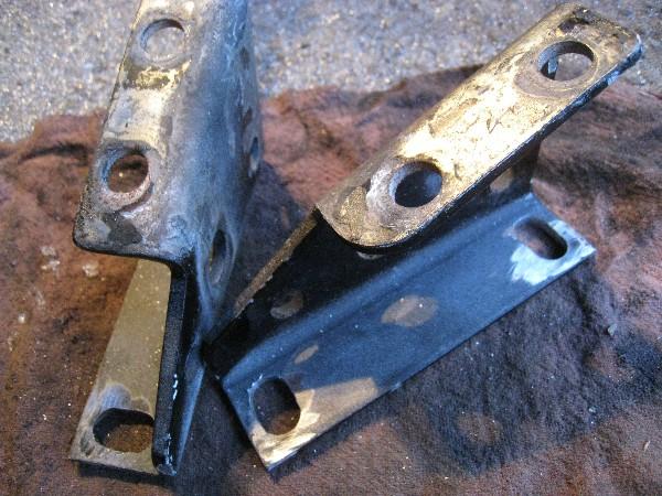
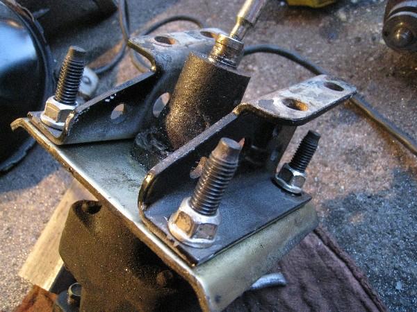
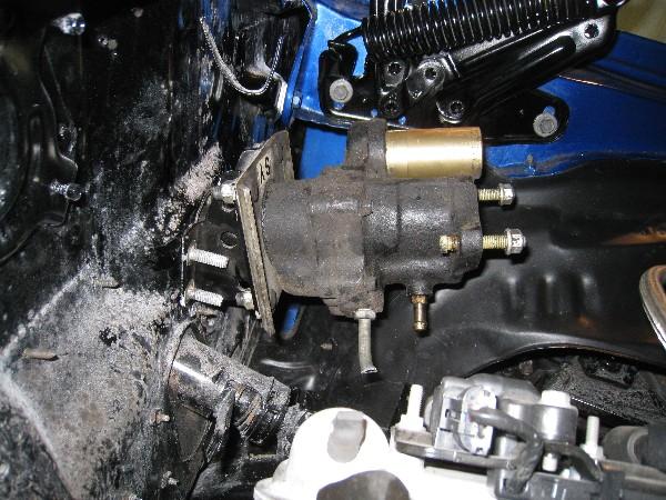

4/14/2009
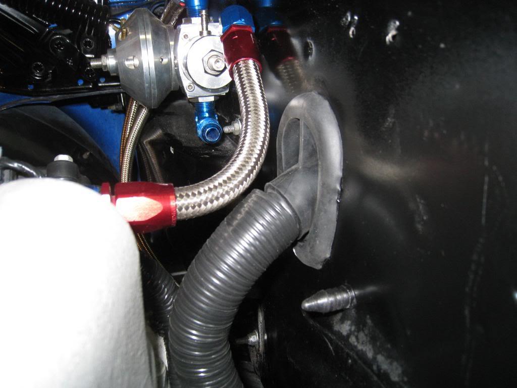
Haven't been making that much progress, things are busy at work! I got a driveshaft made, and installed it. Got an aluminum 3 core radiator, need some rubber saddles for it and I'm looking for a non-chrome heavy duty upper rad support bracket. Ordered a 4" thick x 12 x 24 intercooler. Found a wiring harness grommet at a wrecker so that I can pass my PCM harness into the car. It came off of a 1998 mustang  (at the firewall behind the right fender if anyone wants one) I de-pinned every wire from my PCM plugs, ran them through the grommet, and re-attatched them. TEDIOUS!!!! I could have put a slice in the grommet I guess, but didn't. Funny, it didn't take that long to remove from the mustang!!!! (thankyou SNAP-ON side cutters)
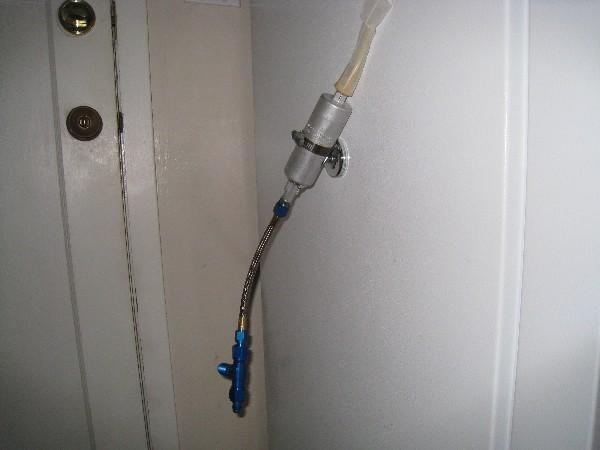
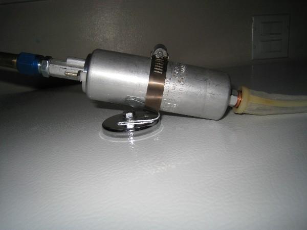
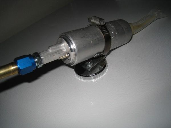
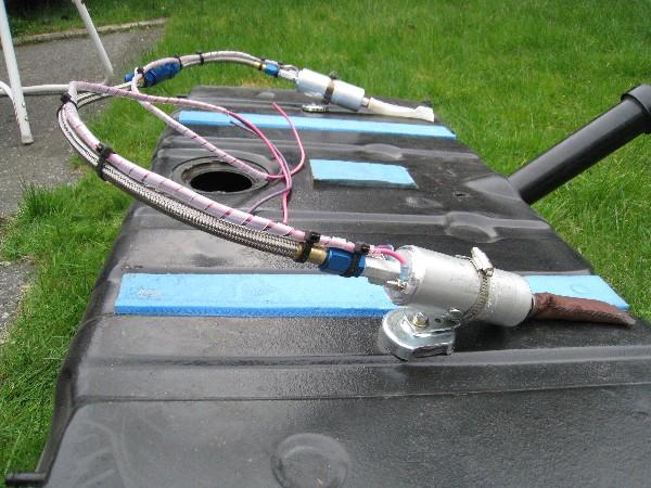
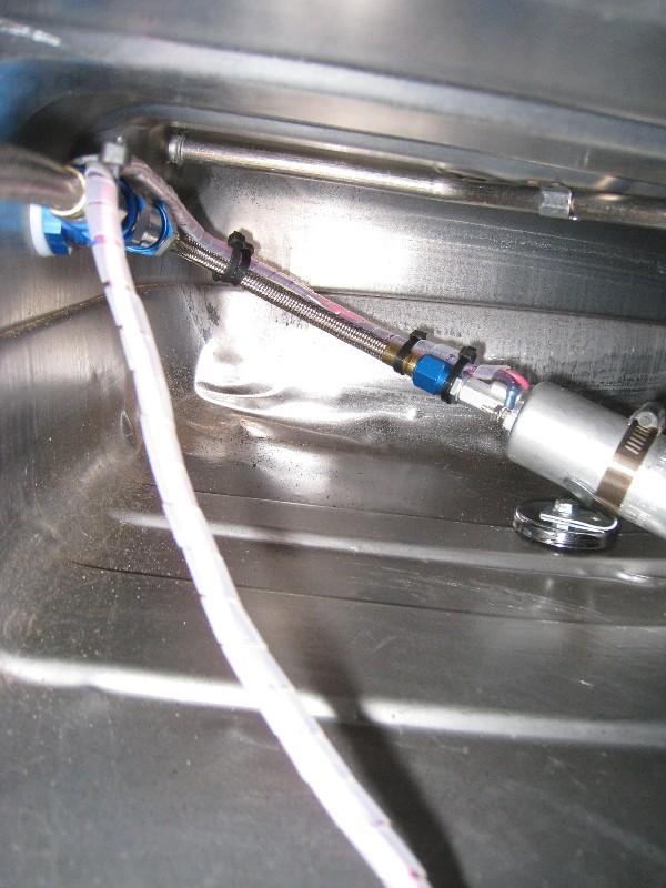
 started on my fuel pump arrangement. Basically, the pump is mounted to a magnet which fits through my stock sender hole. I am going to put a bulkhead T fitting through a hole drilled in the tank in the upper corner near where the stock fuel lines attatch. I have 2 pumps which will be located on either side of the tank, so cornering starvation won't happen. The power wire will then go through a isolater in the stock sender ring....maybe. yes the magnet is strong, there's the assembly hanging on my fridge.
4/15/2009
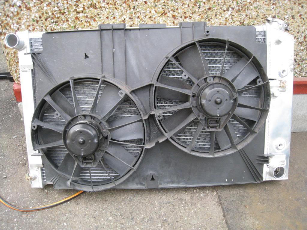
Got a factory fan assembly from my friends at KMS C.A.R. parts. It's a perfect fit for my new rad. Just need to sort out the mounting tabs. Here's the general idea of the fuel pumps.
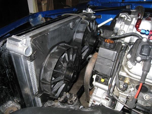
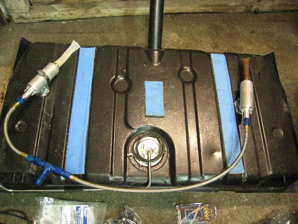
Here's my completed intank dual fuel pump setup. If it doesn't work as well as I want I will cut the tank open from above and build some chambers, and weld in tabs to mount the pumps. I can actually flip this setup upside down and shake it around and the pumps stay put.
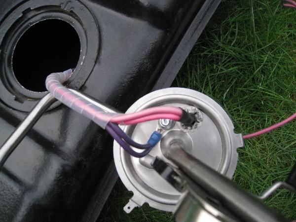
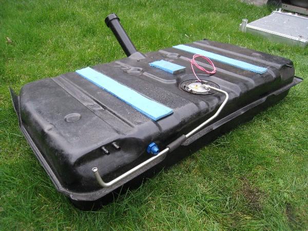
4/20/2009
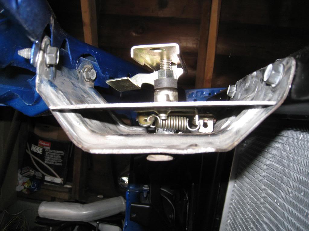
Got some goodies delivered today! Nothing ever simple. Going to have to remove the stock hood latch to provide more clearance for my intercooler.
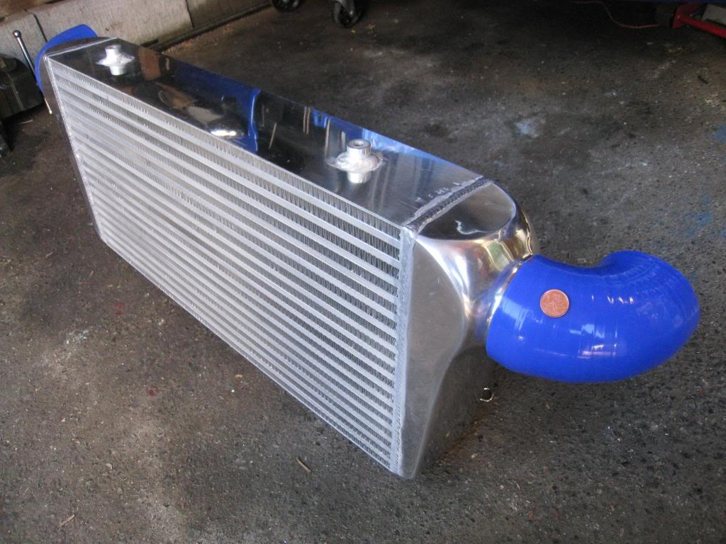
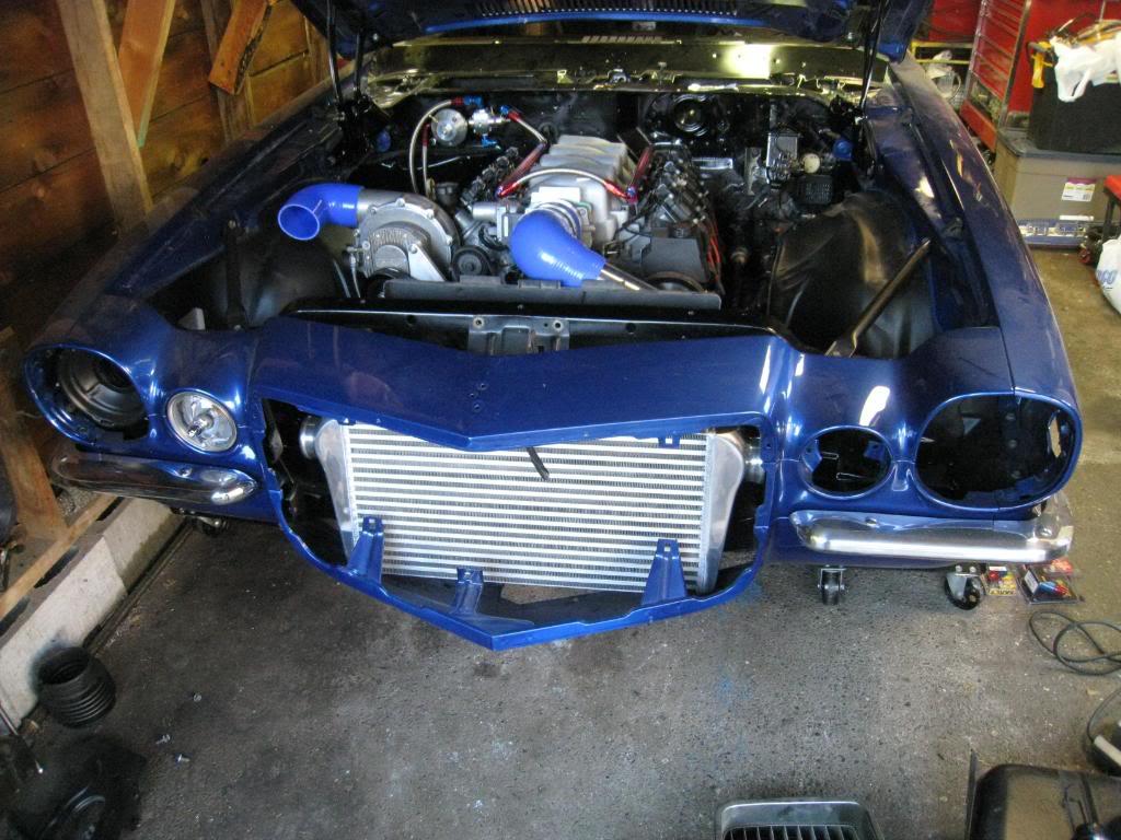
5/12/2009
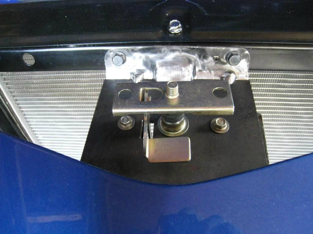
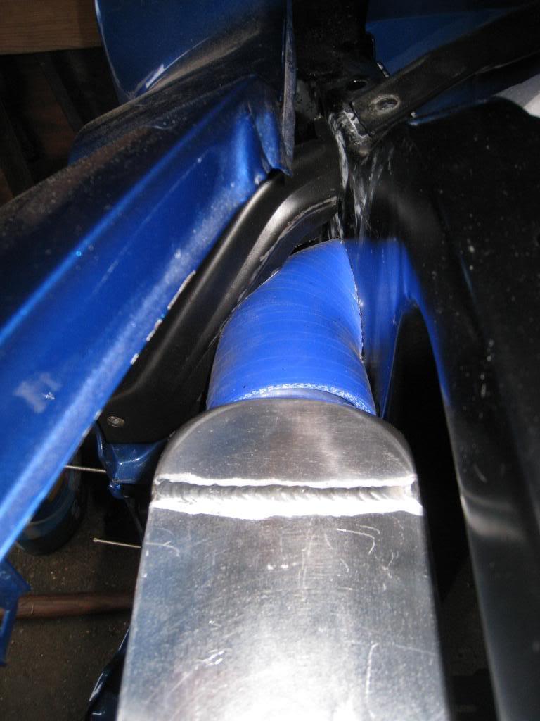
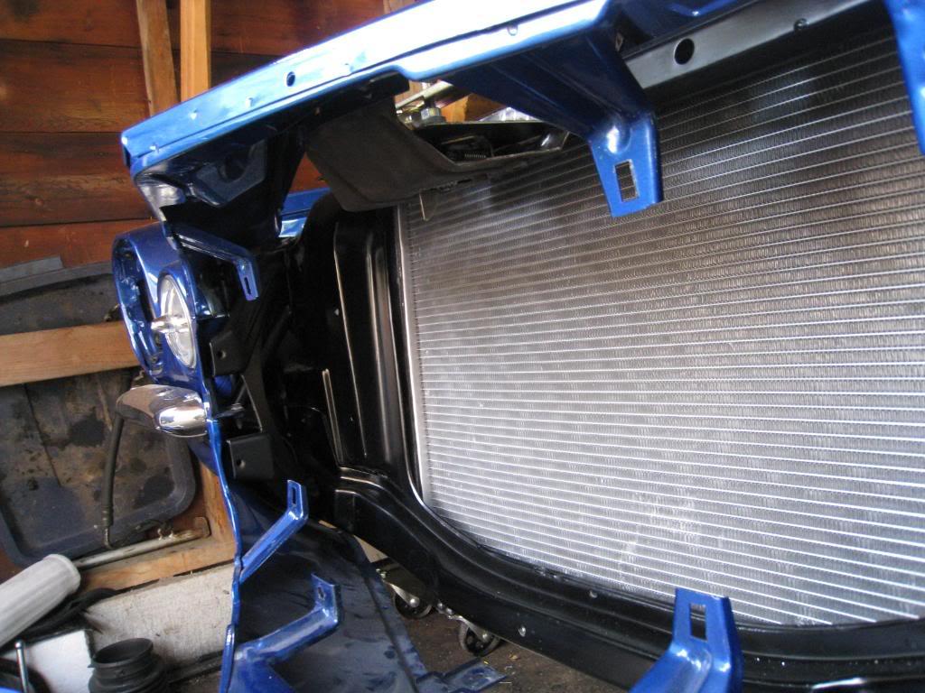
updates? hows your car??? (brother) here's a few pics... made a lower profile hood latch to give me more clearance for my intercooler. Here's the intercooler mocked up with the hose through the hole, here's how the 99 camaro fans went onto the 71 camaro rad. I'll go into more detail later this week. doing overtime again. tired...
5/25/2009
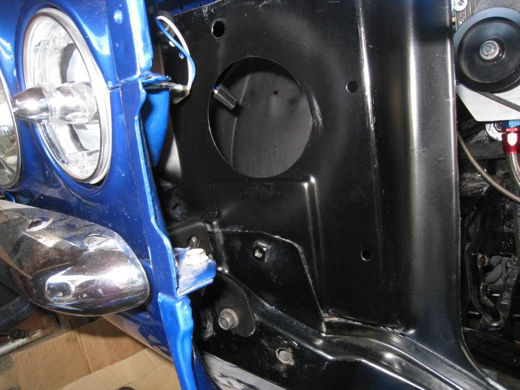
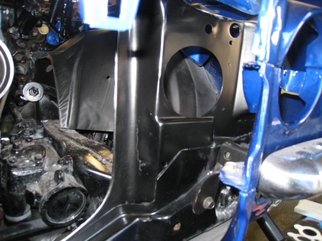
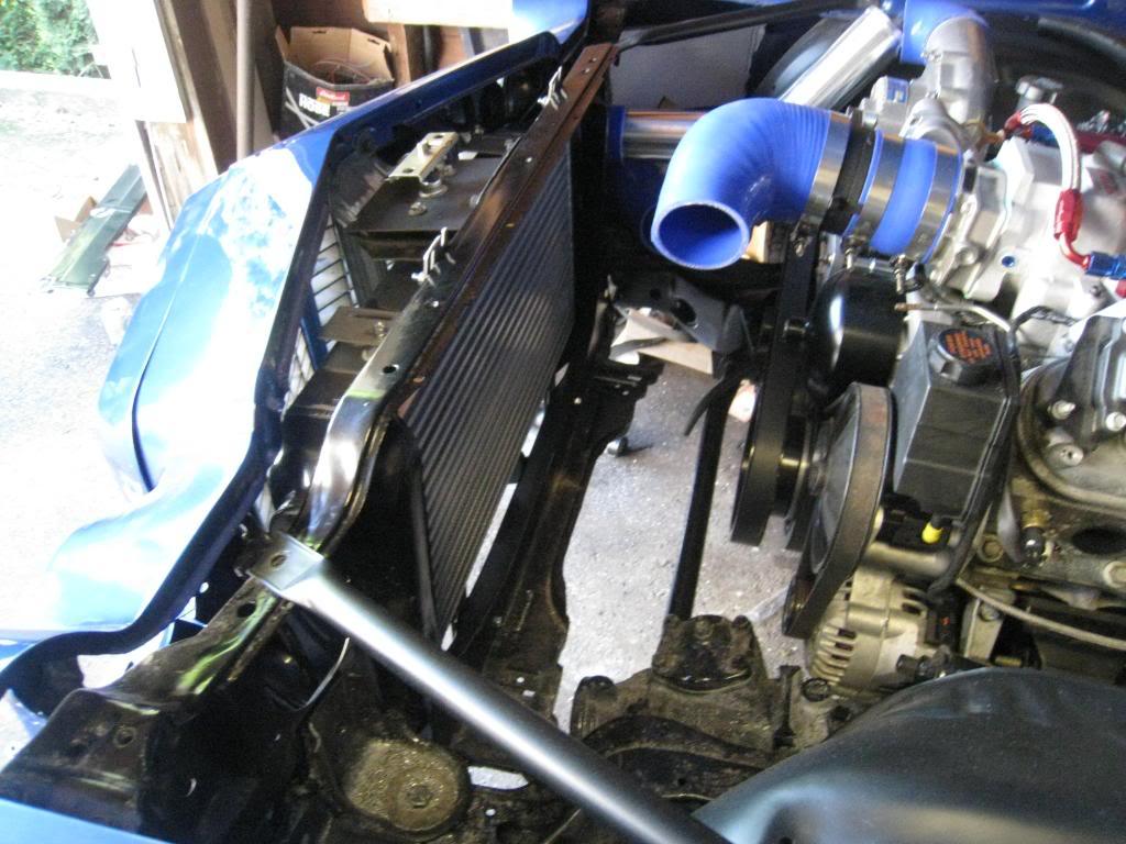
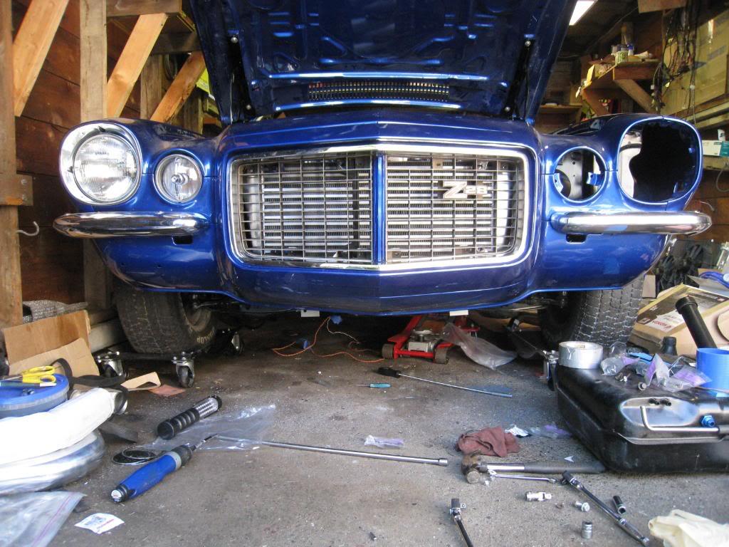
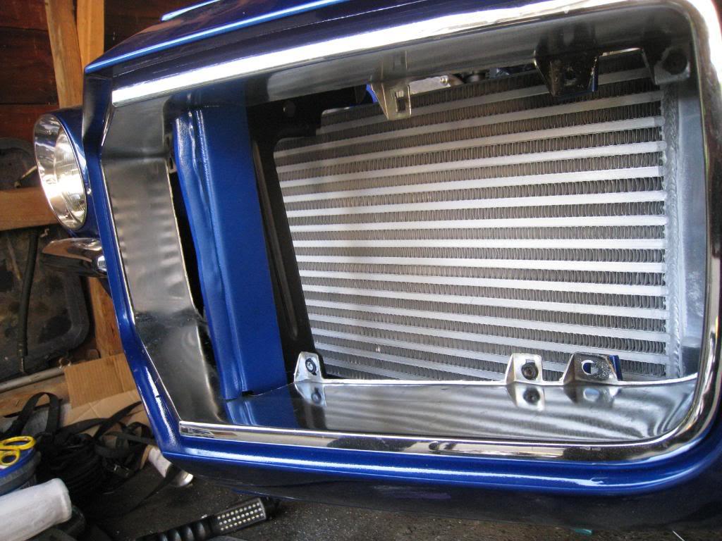
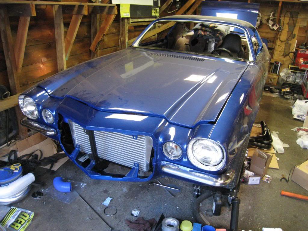
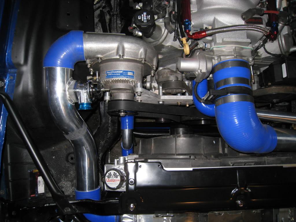
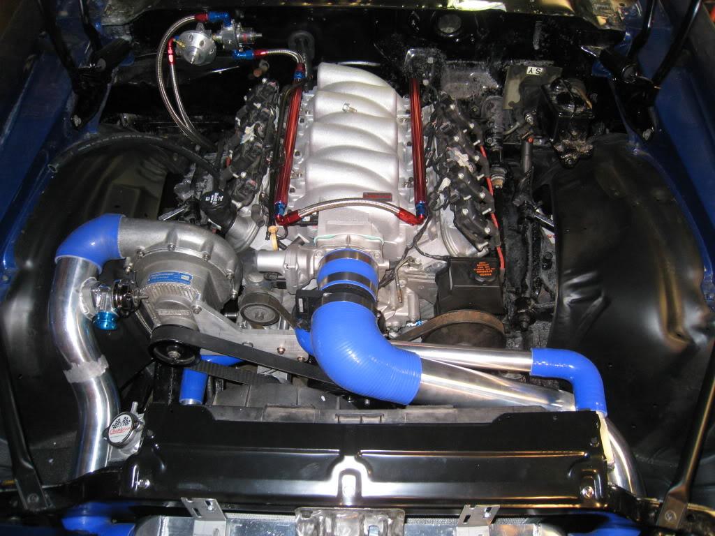
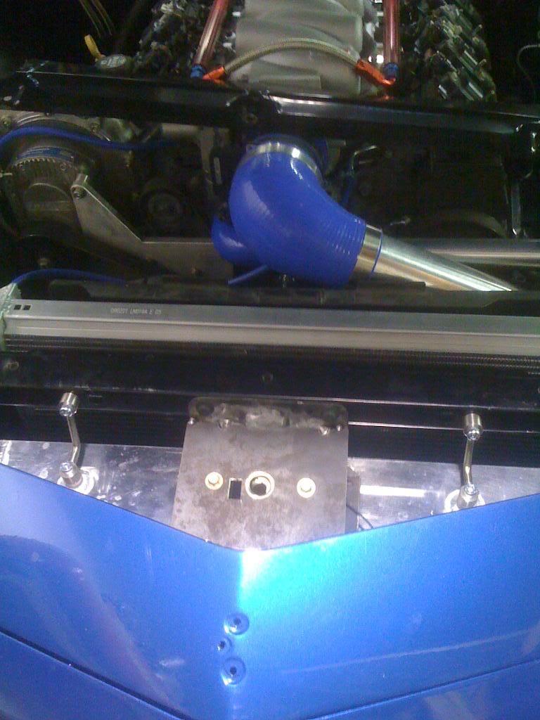
Spent the entire day mounting and unmounting the intercooler. Trying to get the correct spacing for the intercooler hoses and not have them touch anything. Had to remove one of the bumper braces entirely, but it is only the one that goes from the top of the radiator support to the inner bumper brace. Then had to cut a good chunk out of the eurothane bumper bracket so the silicone elbow would clear. I allready modified the hood latch from stock to an aftermarket hotrod type unit to allow more room under the latch. It was all getting very annoying, in, out, in, out, in, out, in...you get the idea!?!?! The brackets you may or may not see in these pics are temporary. I use simple L brackets to mount the cooler, 4 of them, then when I am happy with the fit I pull off 1 at a time and make a replacement bracket. You'll see those later...
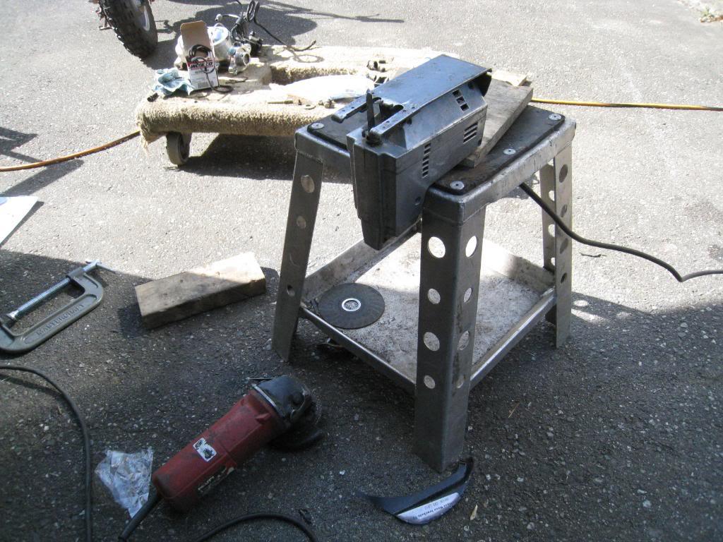
(check out my superfly steel bandsaw table thingy!)

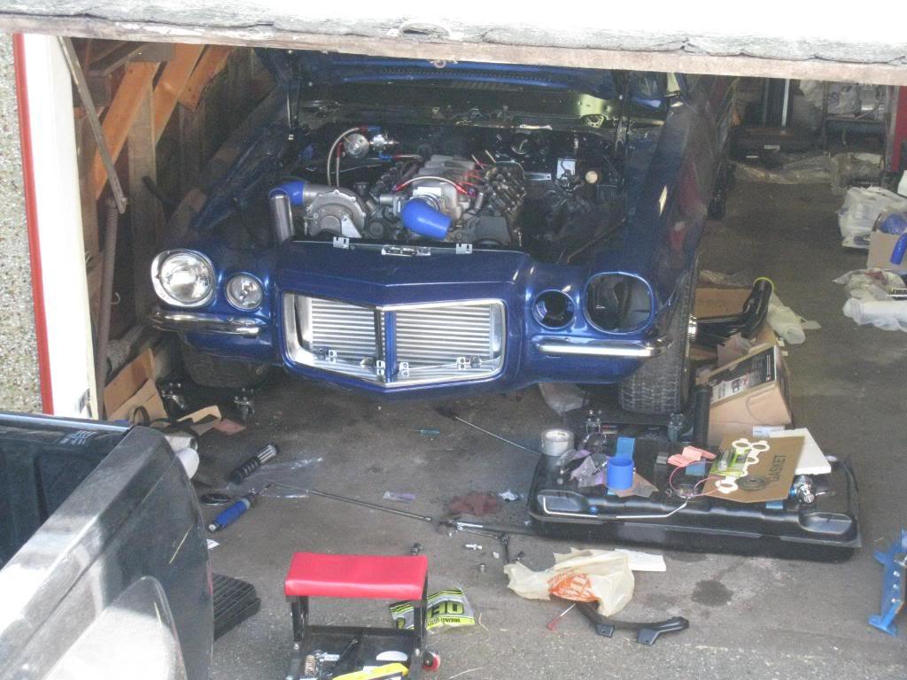
5/25/2009
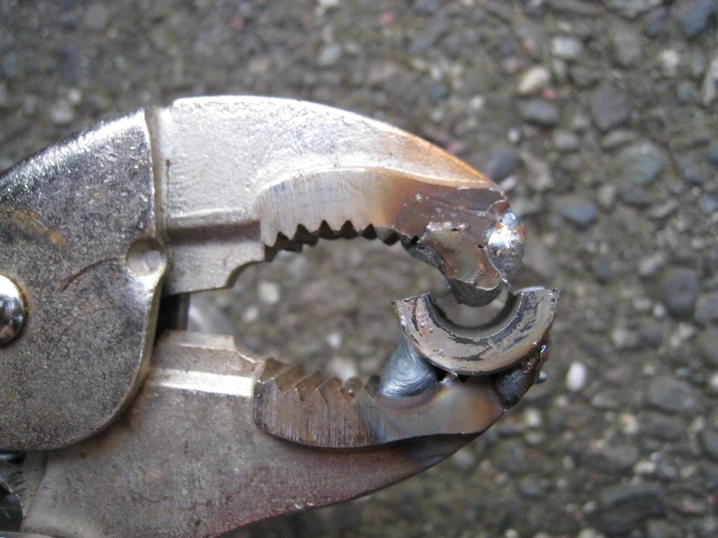
Did some work on the plumbing tonight. Needed to roll the edges of my coolant pipes so came up with this "special tool" had to sacrifice a pair of vice grips but in the end it was worth it. I'm going to change the pipe from the charger to the intercooler, I don't like the sharp bend.
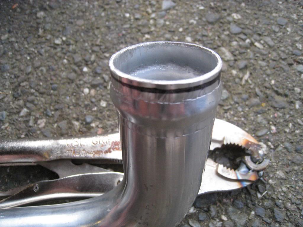
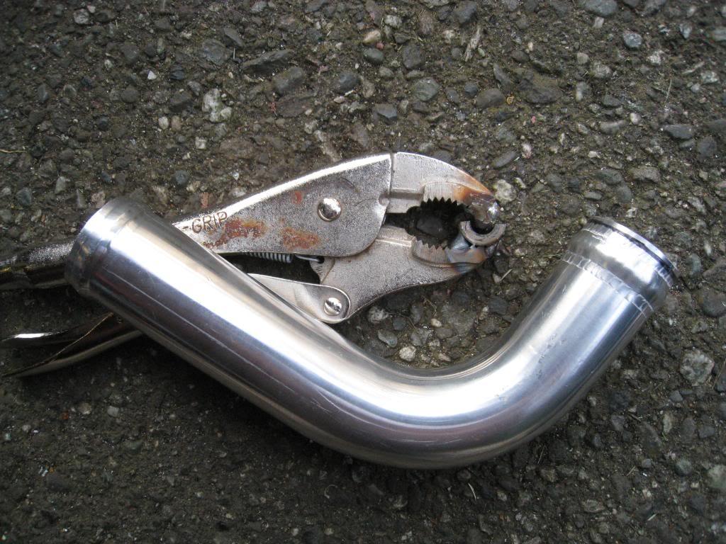
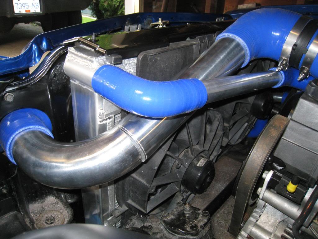
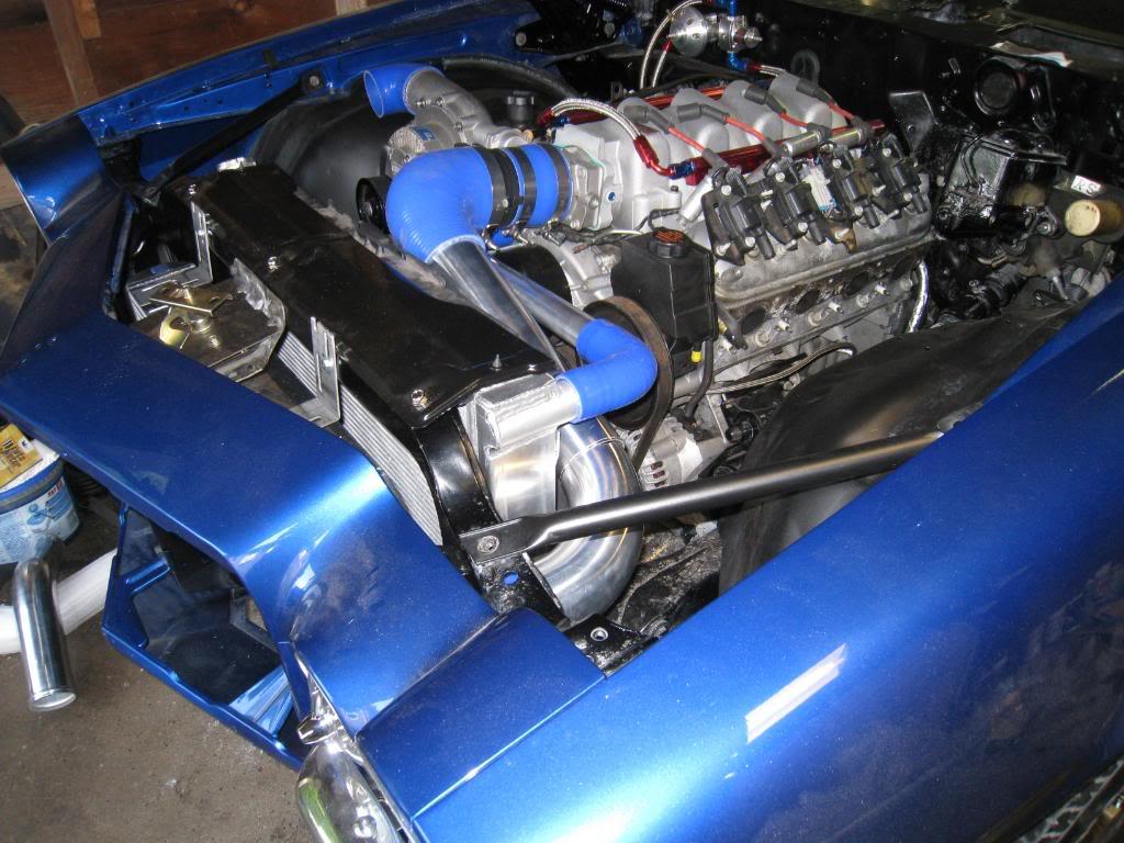
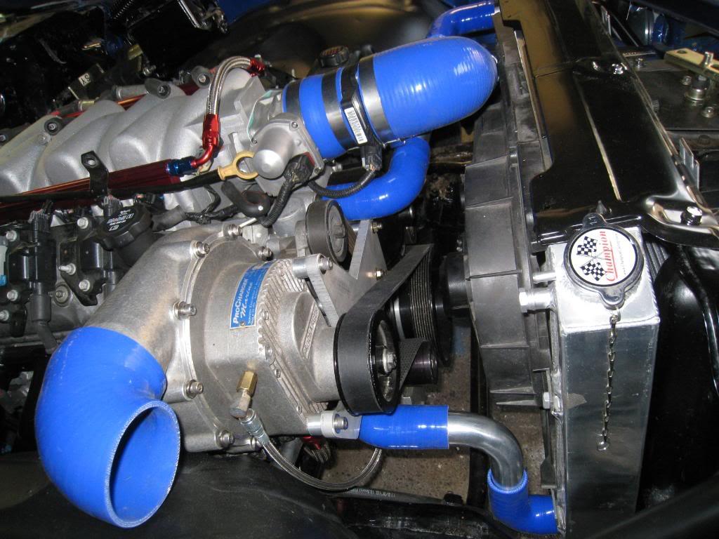
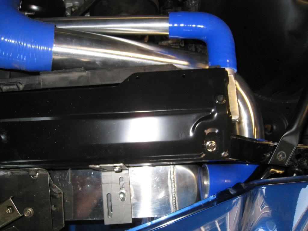
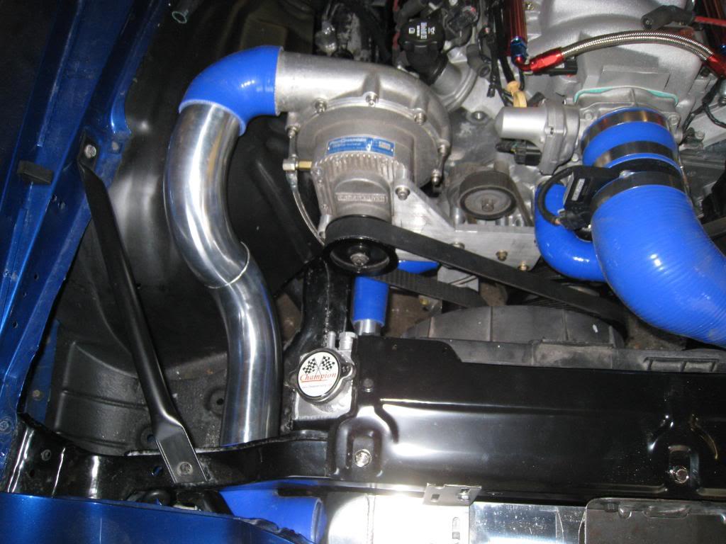
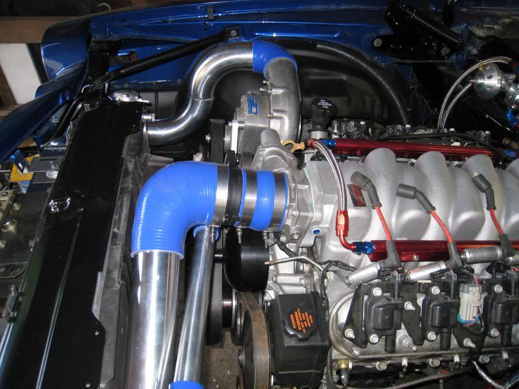
It's a weird angle shot. Closes with room to spare. Here's a shot with the hood closed.

5/27/2009
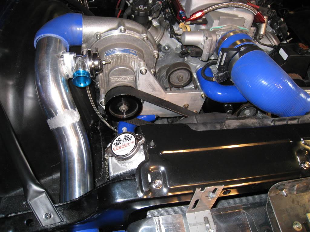
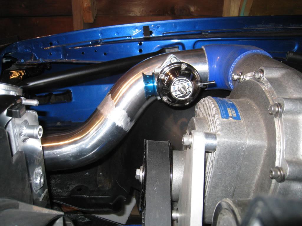
Got the last intercooler pipe finished today, or at least fabricated. Haven't decided on the actual finish for all this stuff yet... I think I may paint it all black with a heat blocking paint to try and keep the intake temps down. This build has been a rollercoaster of emotions. Some days it's just way too much, then others it seems like I just might make it!

5/29/2009
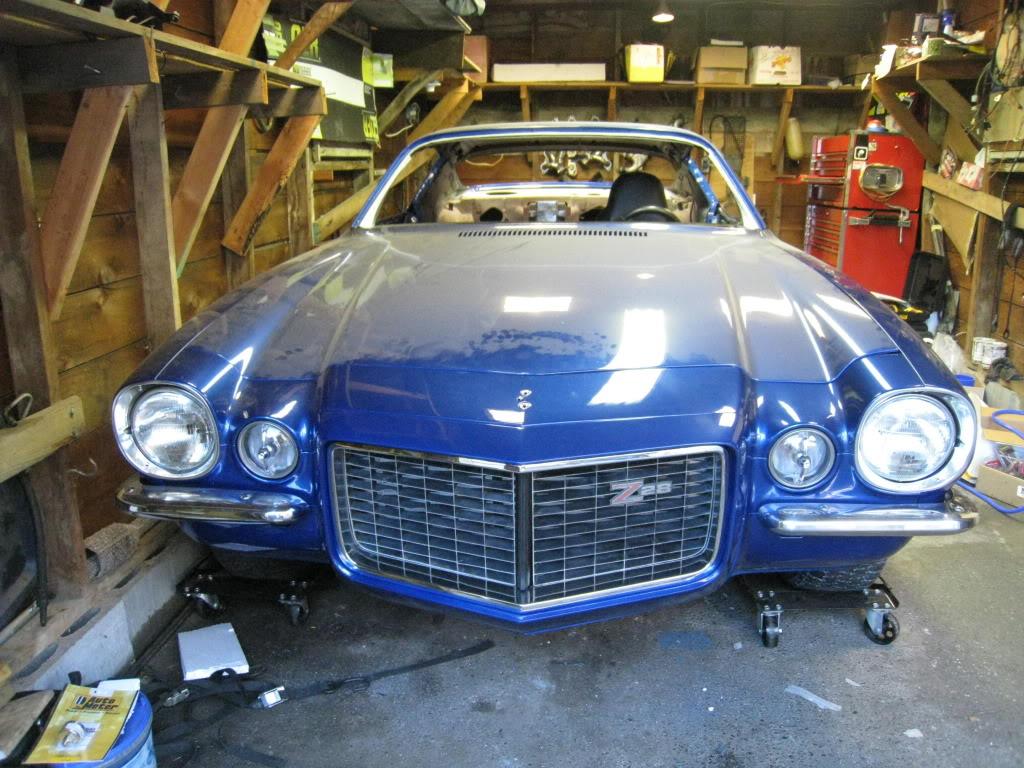
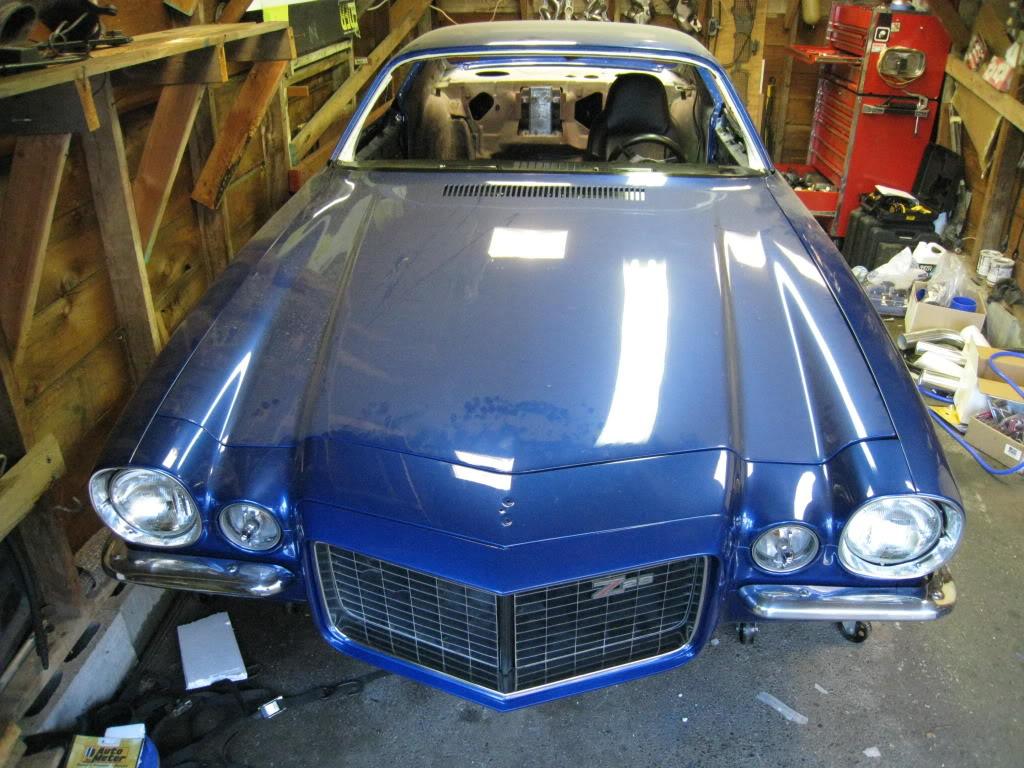
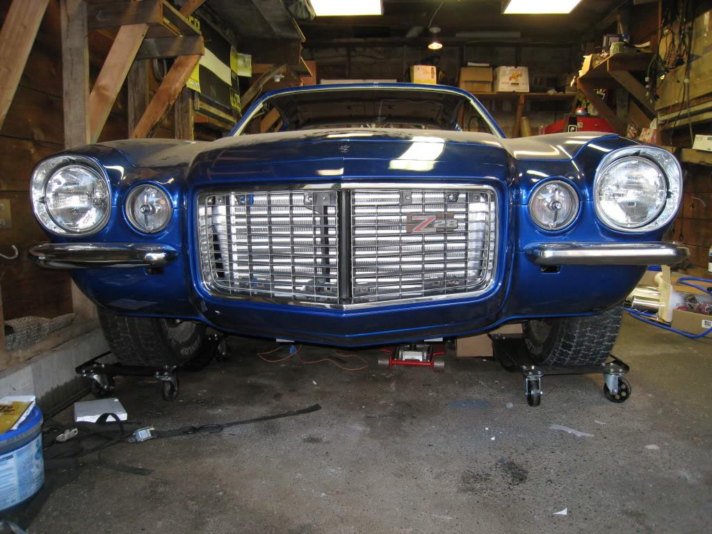
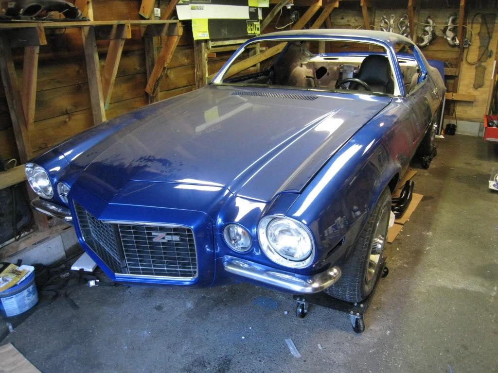
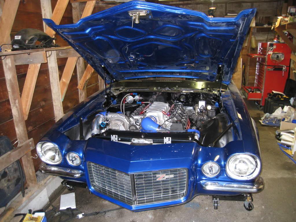
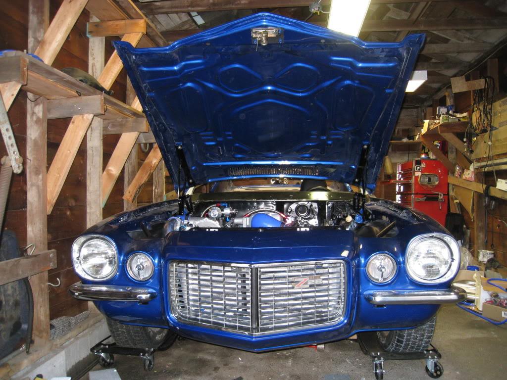
A little more progress over the last 2 nights. Plumbing all clamped down, hood latch tack welded and adjusted, eurathane bumper mounted and grille test fit. Still need to adjust the bumper part. (tricky)
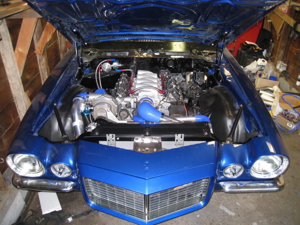
6/5/2009
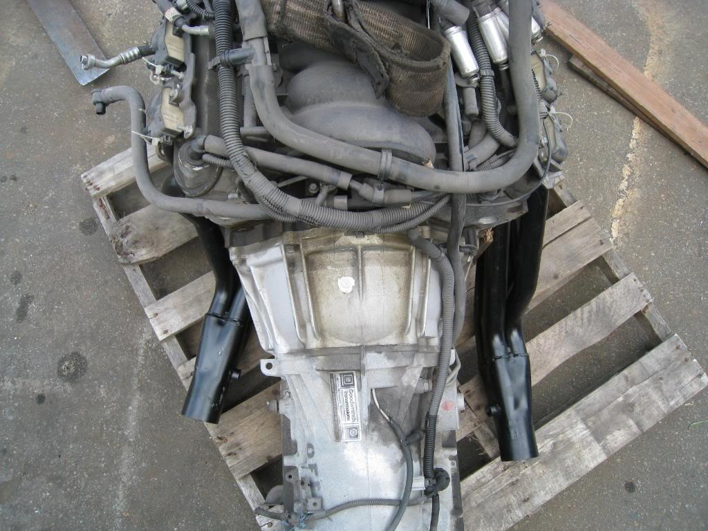
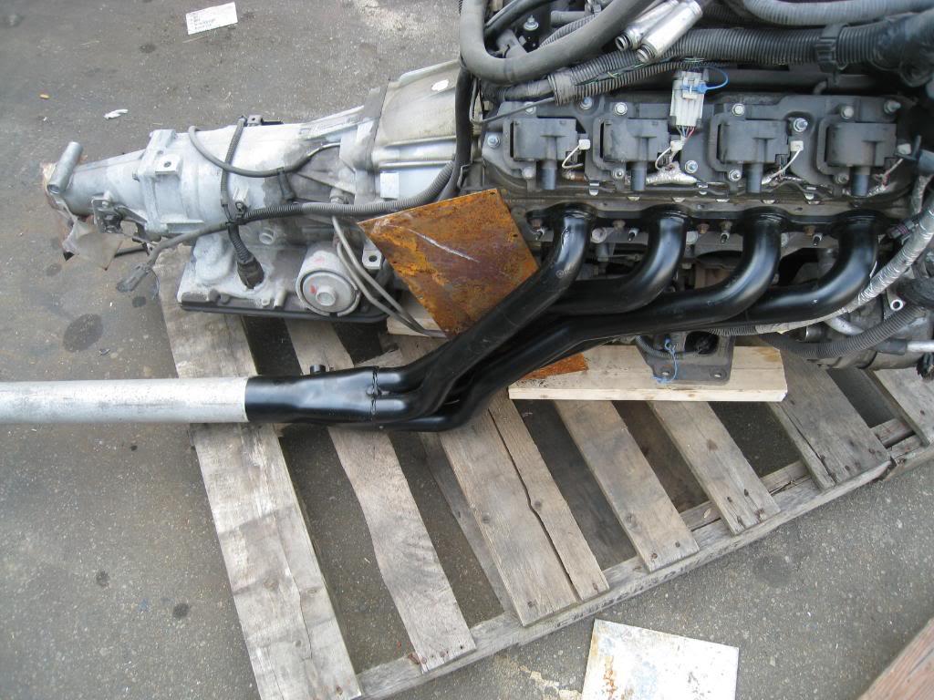
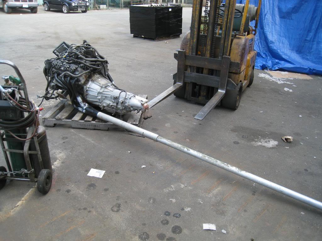
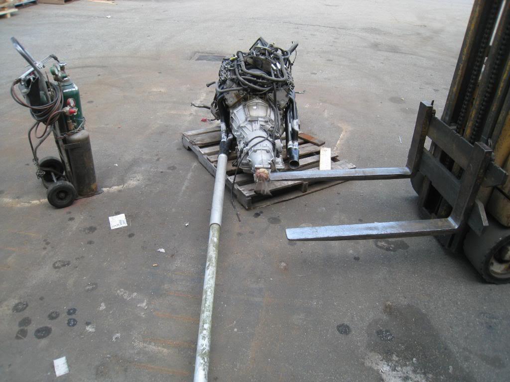
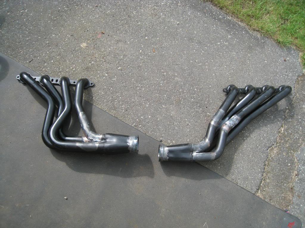
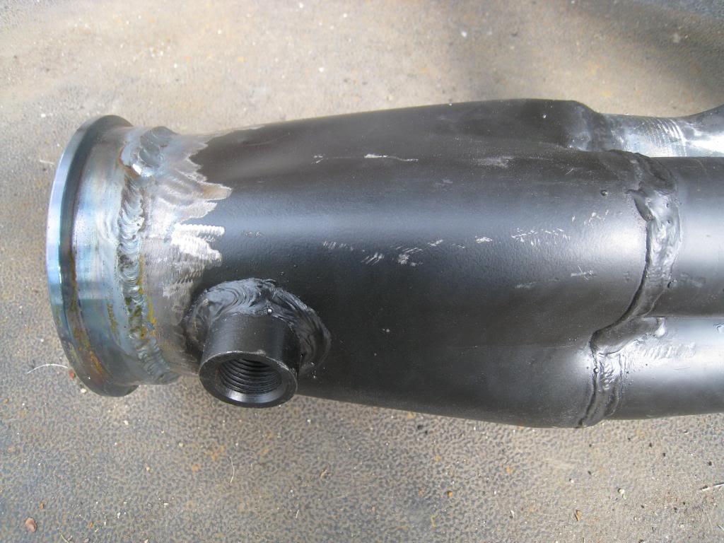
Worked on the Headers tonight. I decided to go with the heat and bend technique. I went down to K.M.S. Car Parts spoke to Richard there and he graciously let me borrow a LS1 with a transmission in order for me to 'adjust' my headers. I bolted my headers onto the motor, secured it with a forklift, found a piece of pipe that fit inside the collector perfectly, then heated and bent the pipes to where I wanted them. I used bits of wood and sheetmetal wedged into certain spots to make sure that the pipes didn't just wrap themselves around things that they shouldn't. Realisticaly the could have been used with very little bending, but I am trying to get them to line up more with my crossmember. Overall, I got the passenger side pipe to come in 3" and the drivers side to come in almost 4"
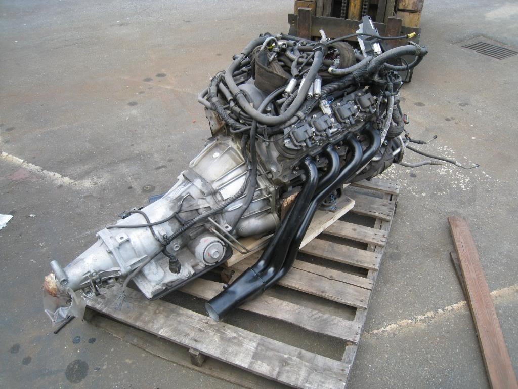
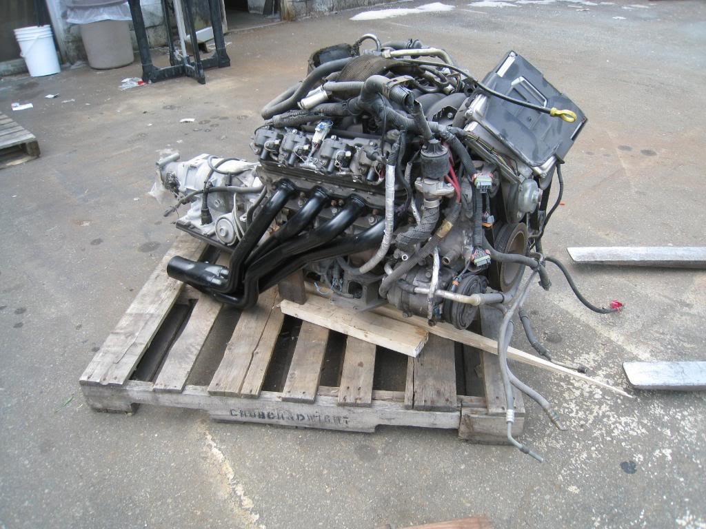
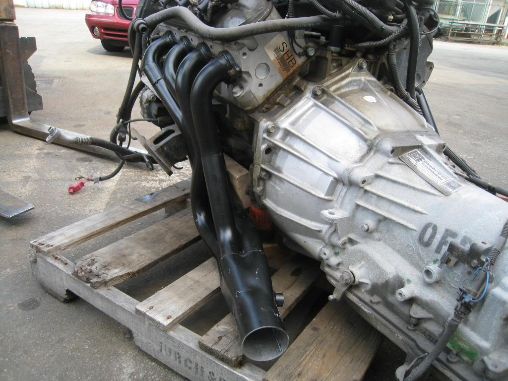
6/9/2009
I dropped the headers off at my local metal cleaners today, getting them cleaned then I am going to coat them with a product called turboX. My brother used it on his turbo housing and it is a very effective heat blocker. Plus it stays nice and black and doesn't discolor. Here's some more pics.
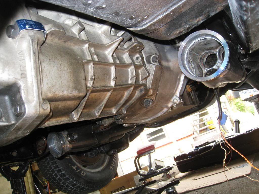
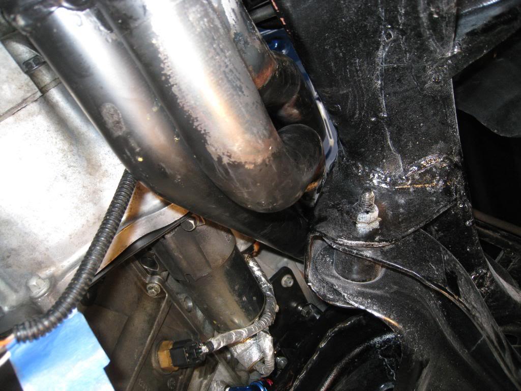

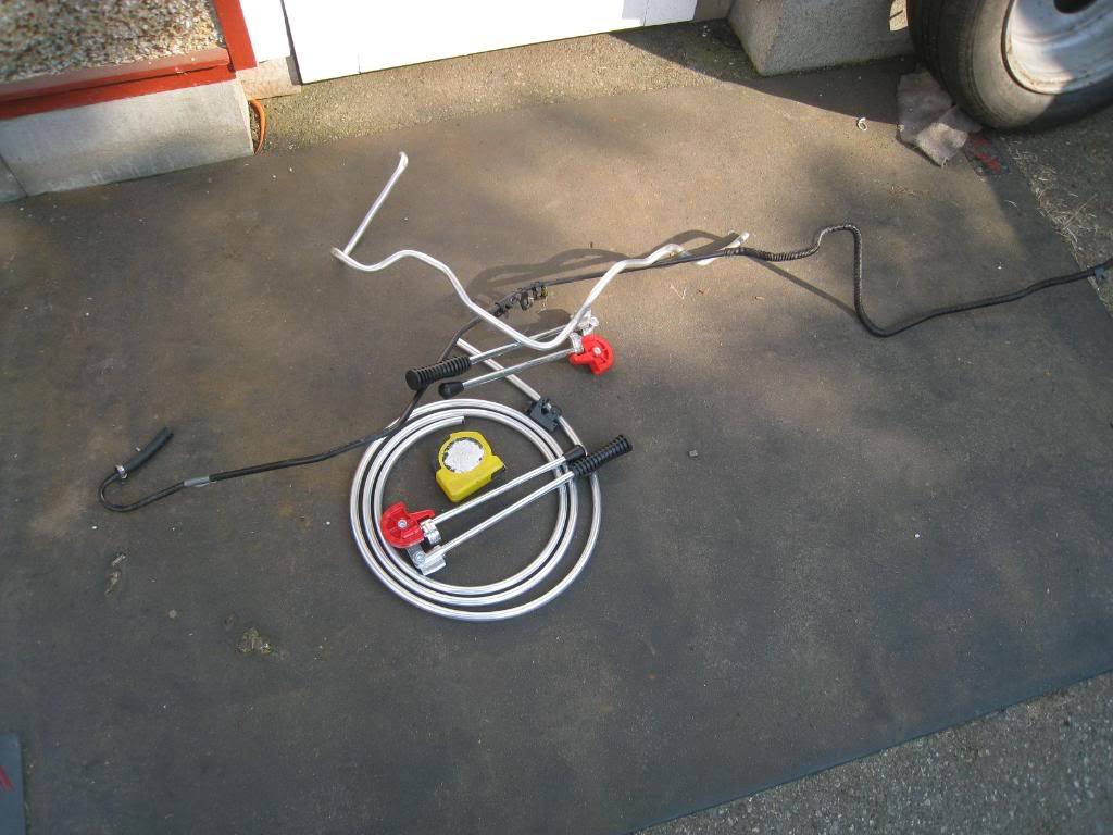
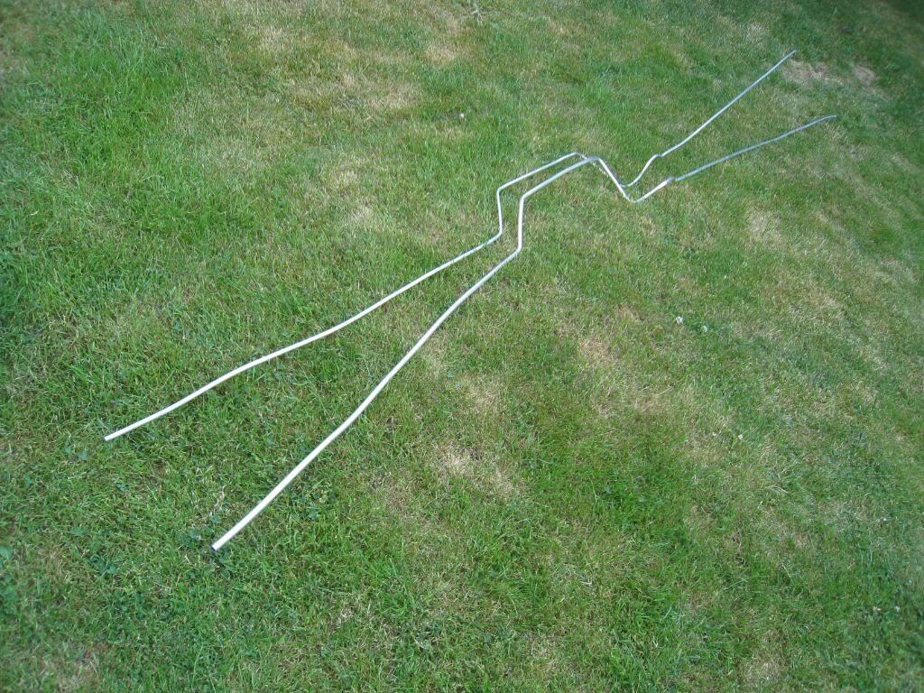
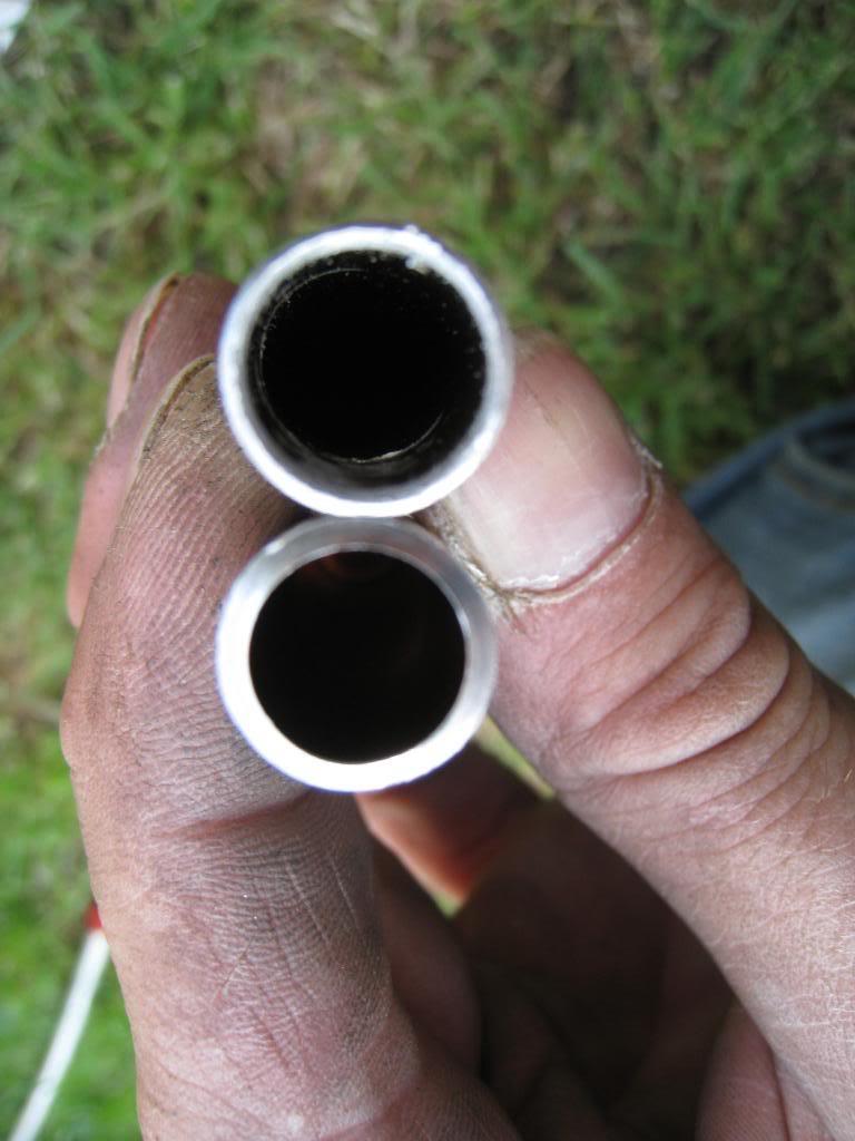
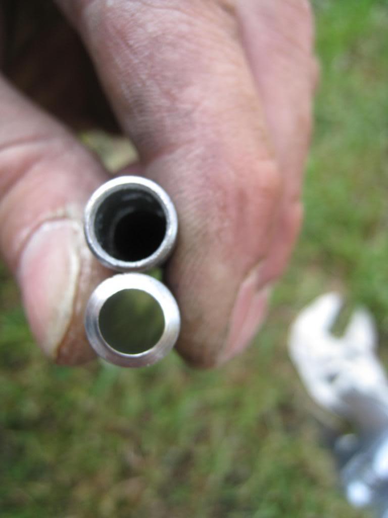
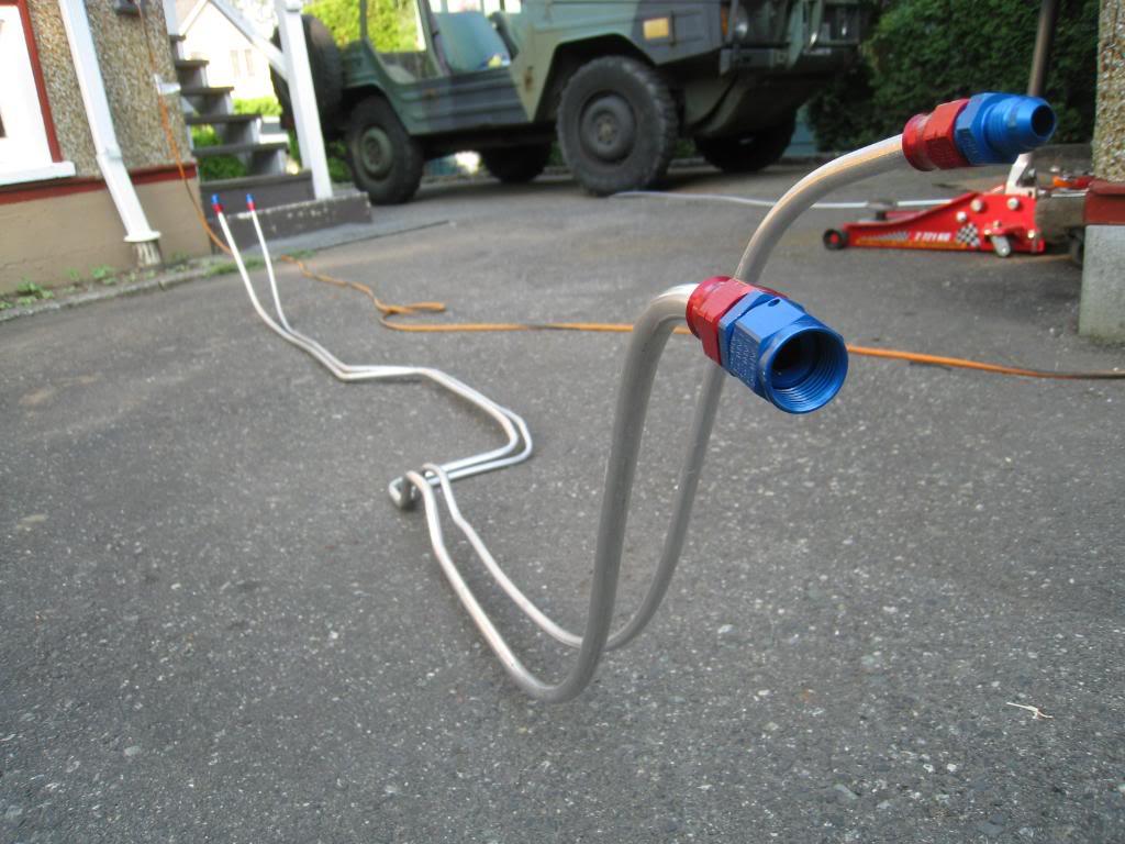
Built hard fuel lines this afternoon. Not an easy task with the car only 2 feet off of the ground. For those of you who might do the same, don't forget to ream out the line after you cut it. The pics show just how much the line collapses after a spin cutter. Also, a good tip is to copy your old line before you go under the car. I went with a 1/2" feed line and 3/8" return.
6/11/2009
Got my hardlines clipped in. Purged and pressure tested the system. Damn! leak at the regulator. Turns out it was a bad fitting that galled the regulator as it went in, then removed the threads when I took it back out! I disassembeld the regulator and ran a tap into the bad hole as deep as I could and replaced the fitting. Fingers are crossed. Will retry it tomorrow.
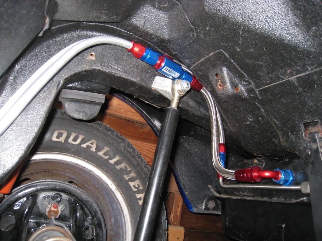
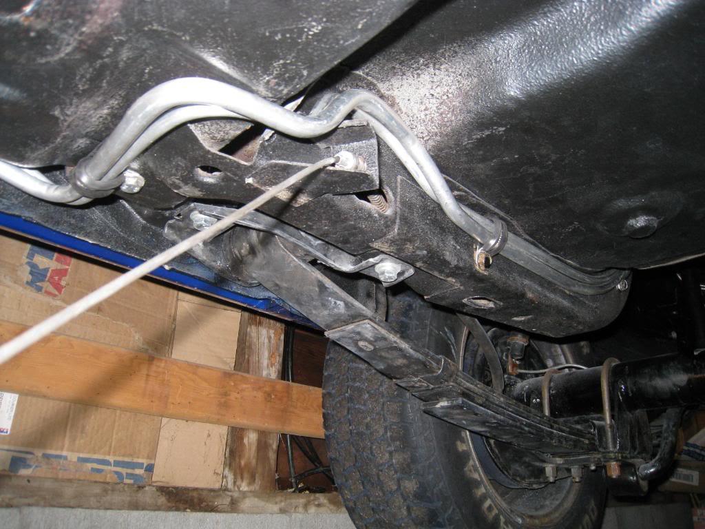
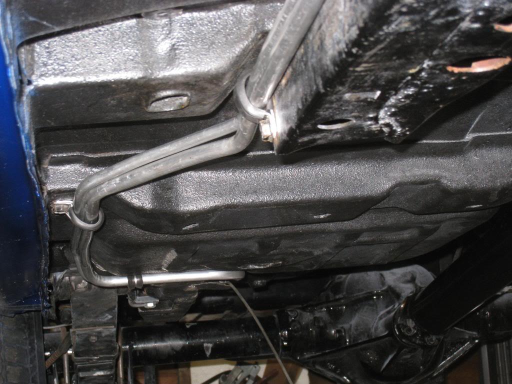

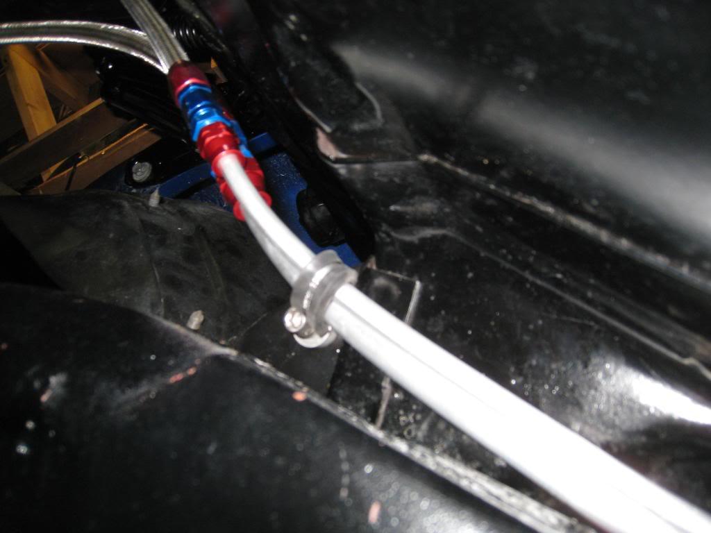
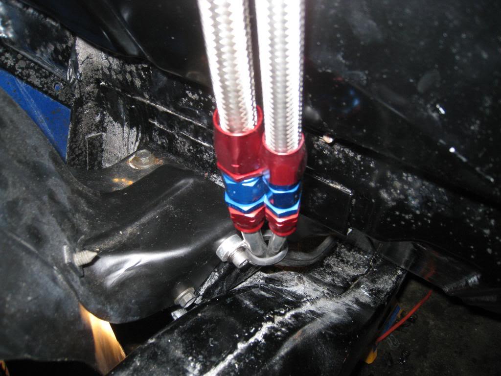
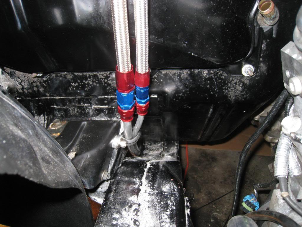
Success! Installed my regulator assembly and pressure tested. No leaks. Regulator is set at 54 psi. Does that sound about right? I think I have heard 56psi...
6/14/2009
Installed a power steering regulator today. Plus, FIRED IT UP!!!!! thats right, I ran the motor today! open headers, but oh well, been over a year in the making. Sounded great. more on that later!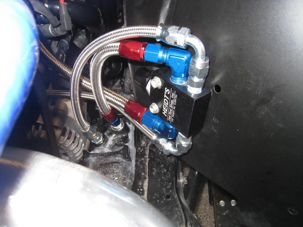
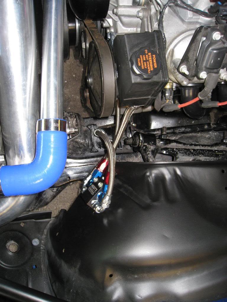
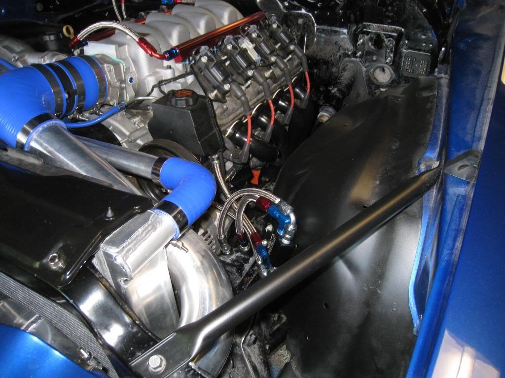
6/14/2009
Modified the throttle pedal today, plus did a little more wiring...always more wiring!!!
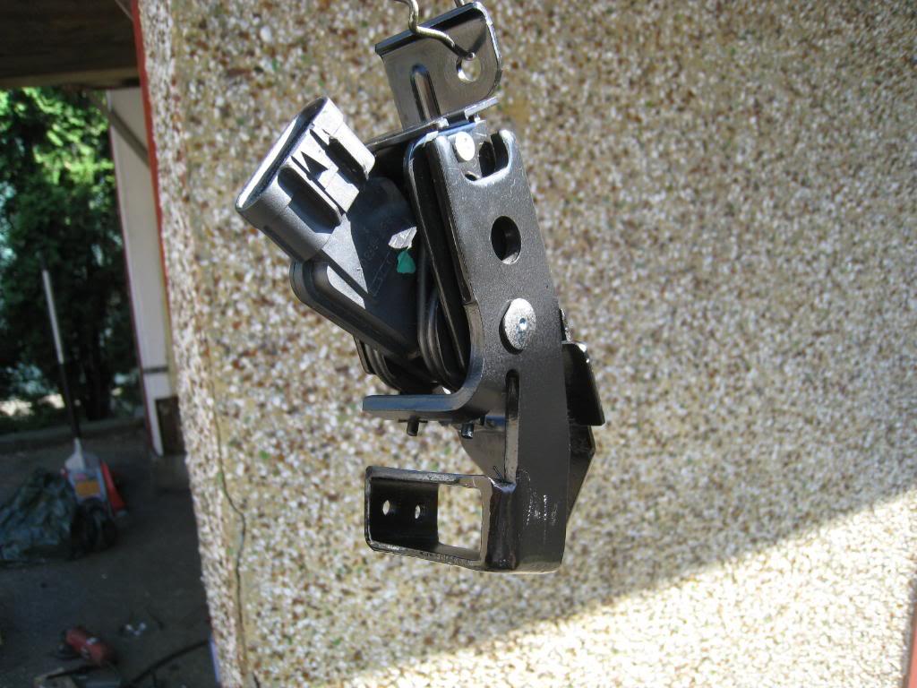
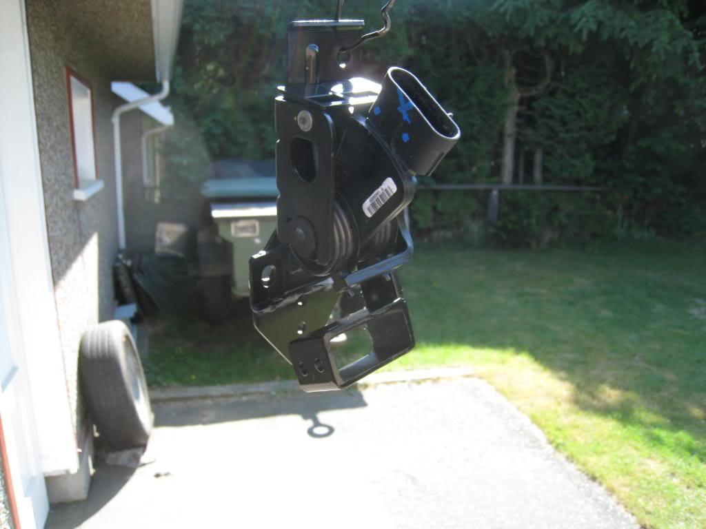
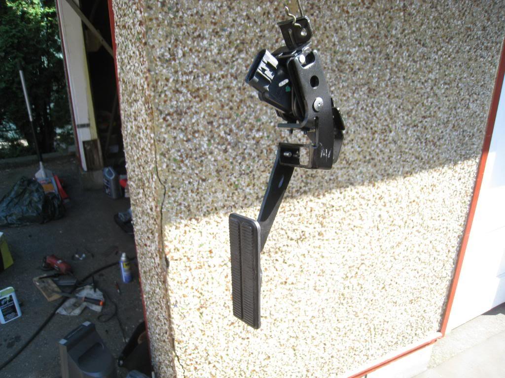
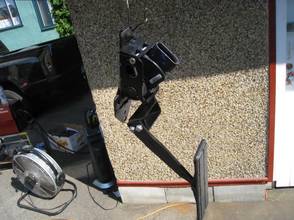
6/17/2009
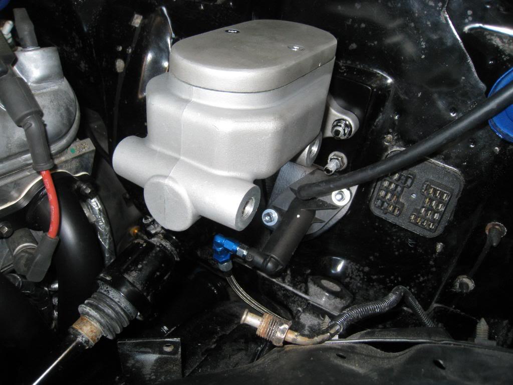
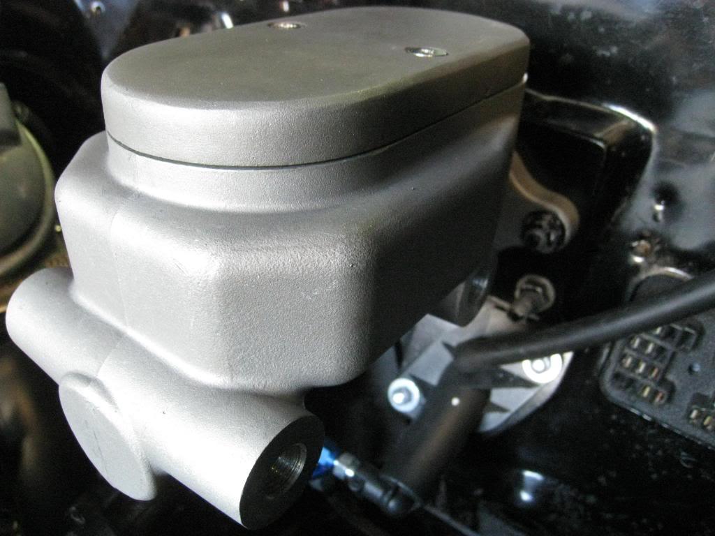
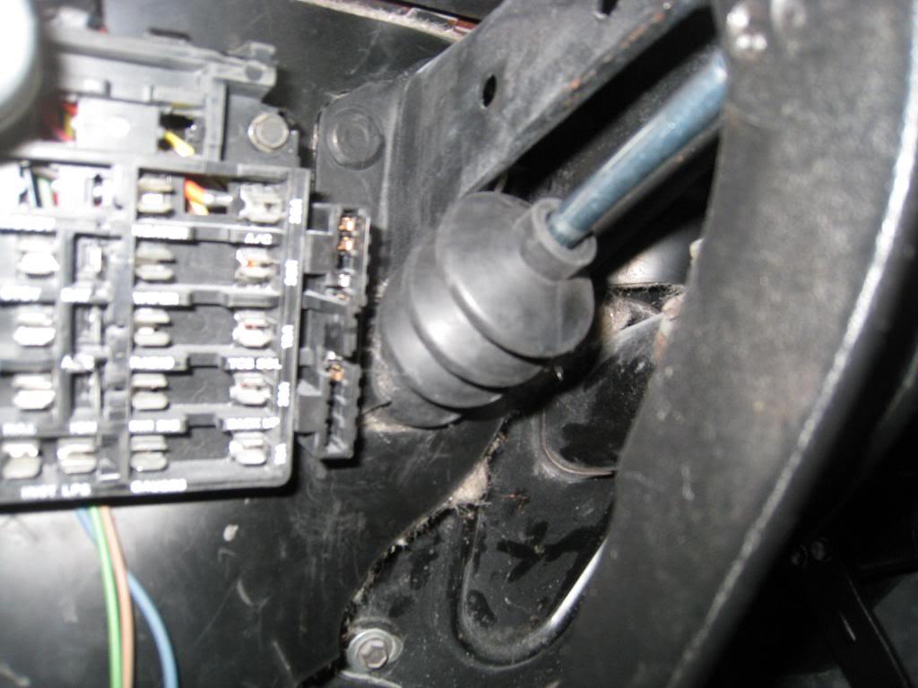
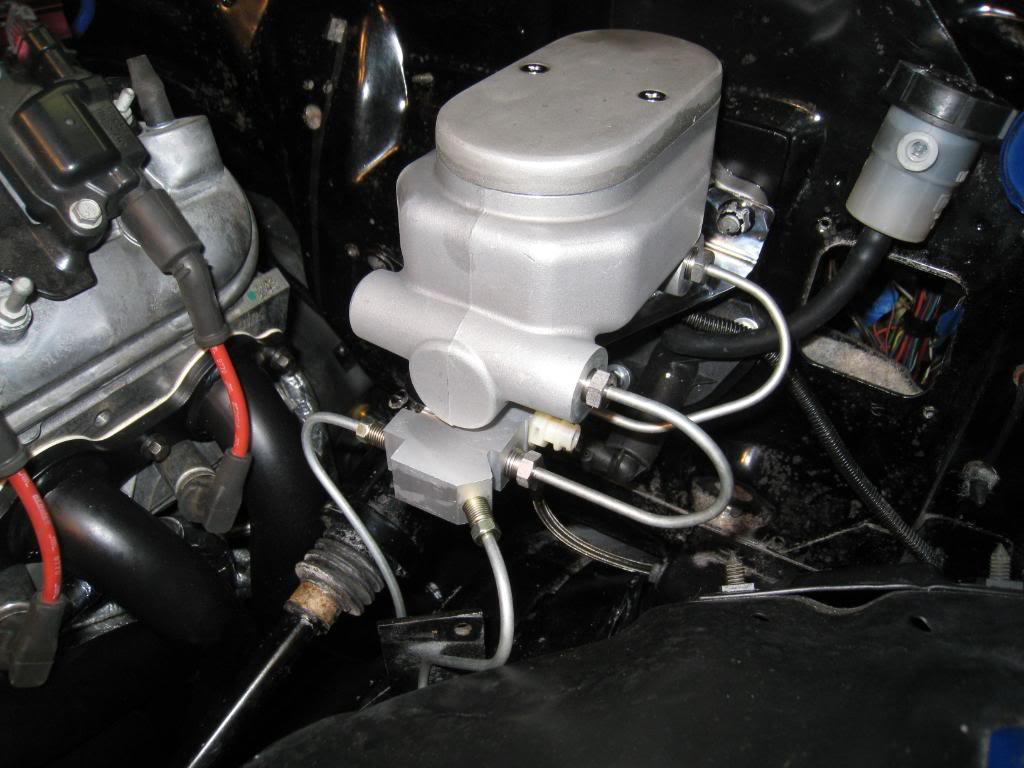
Yet another trip down to K.M.S. Car parts. Picked up a new brake master cylinder. I fabbed up my own clutch master mounting bracket. I started out with a blank piece of paper, the firewall, and a pencil. I bent the bracket about 15 degrees, then bolted it onto the firewall. I ended up "tweaking" it a bit more so I don't really know what the final angle was. The pedal feels a little heavy, but not too bad. There is a centerforce clutch in there too so I don't really know what it should feel like. I used the original pushrod grommet but instead of mounting it on the outside, I flipped it over and mounted it from the inside. It covers the entire master, and give me a weather tight seal. I have decided to go with manual brakes so that I can have the best brake feel for my projected road course track days.
6/26/2009
Got some more stuff done. Brakes are hooked up and bled. Spent some time in front of the milling machine and made my battery disconnect.
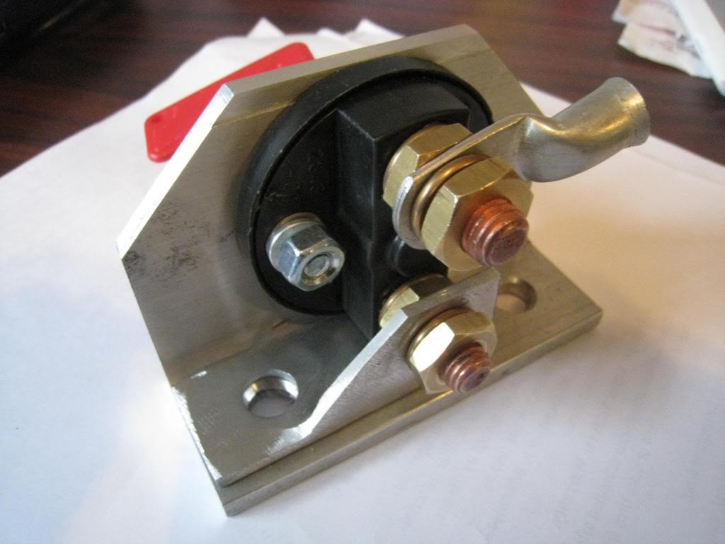
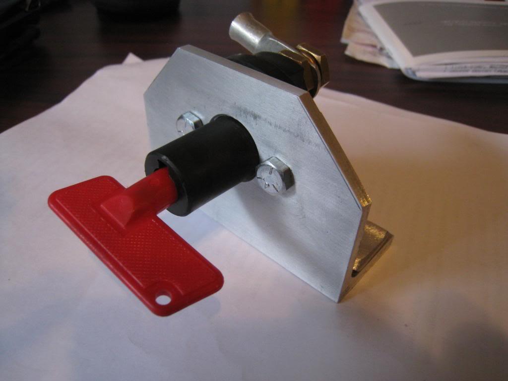
6/27/2009
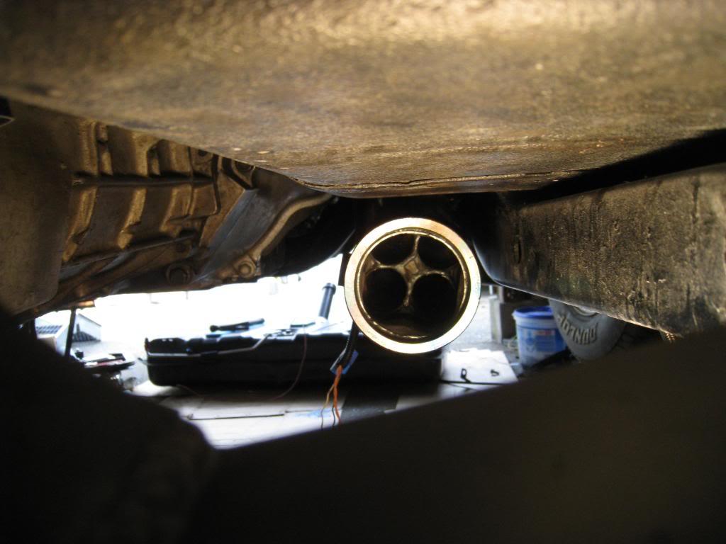
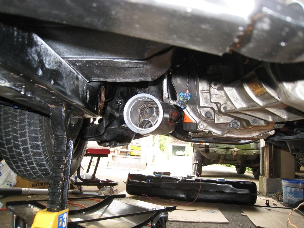
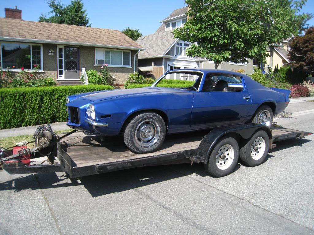
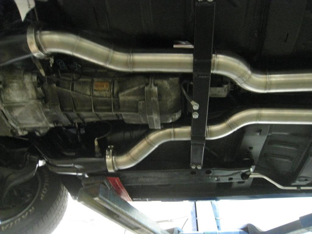
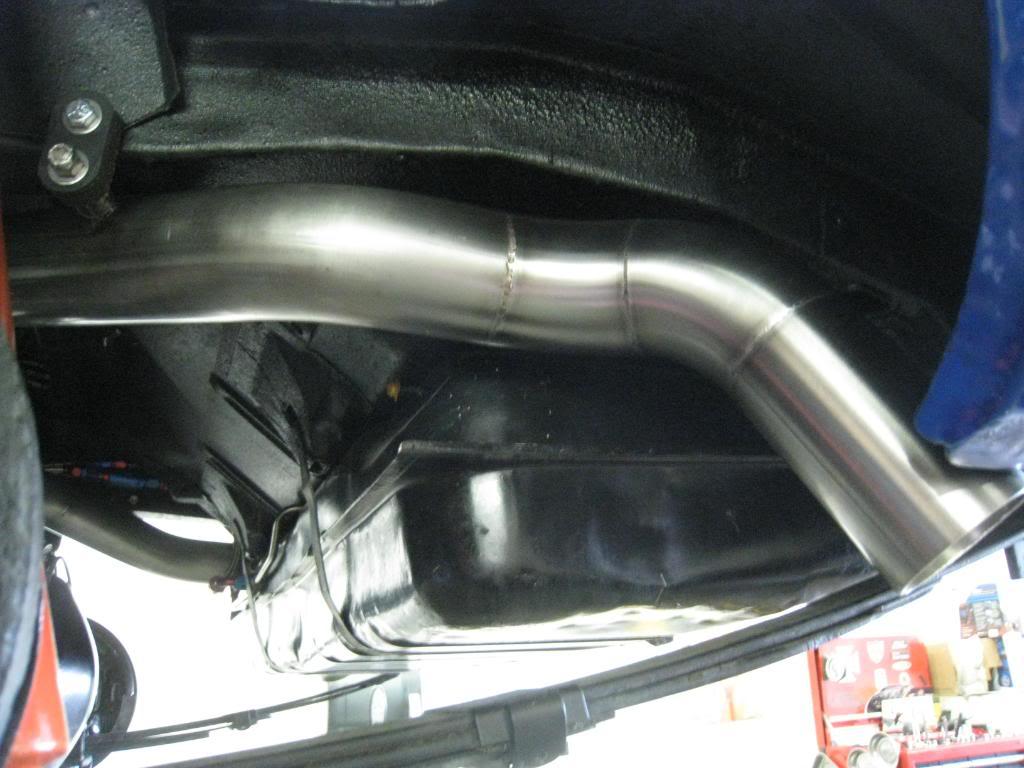
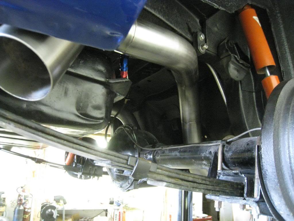
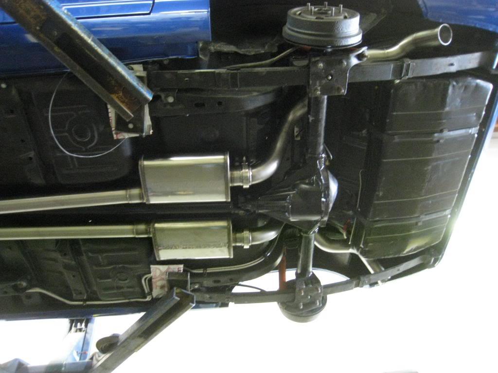
Took the car out of the garage undr its own power!!! fun!!! neighbors love it!!! or maybe not... took it to my friends shop, Custom Metalcraft, (604-468-7702) and started doing my exhaust system. They build a lot of cool stuff there, so if you need anything, give em a call. ask for Ryan or Mike. Tell em Mark sent ya. Anywho. Ya, spent 1/2 a day under the car building exhaust...here's what ya get!
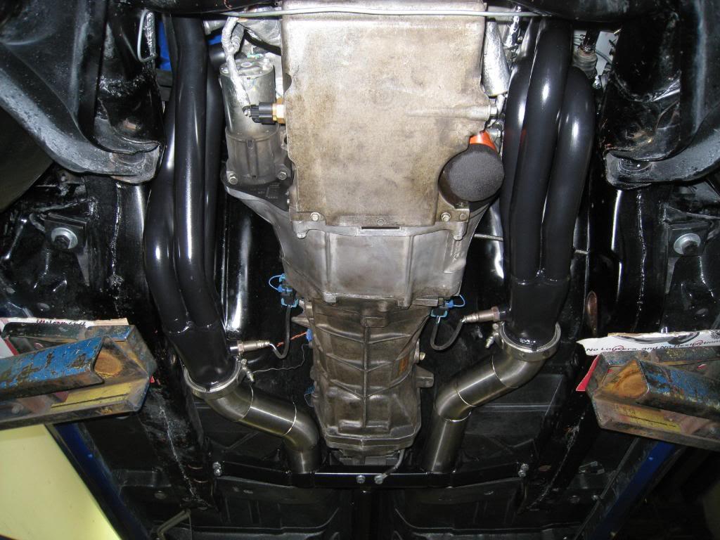

6/29/2009
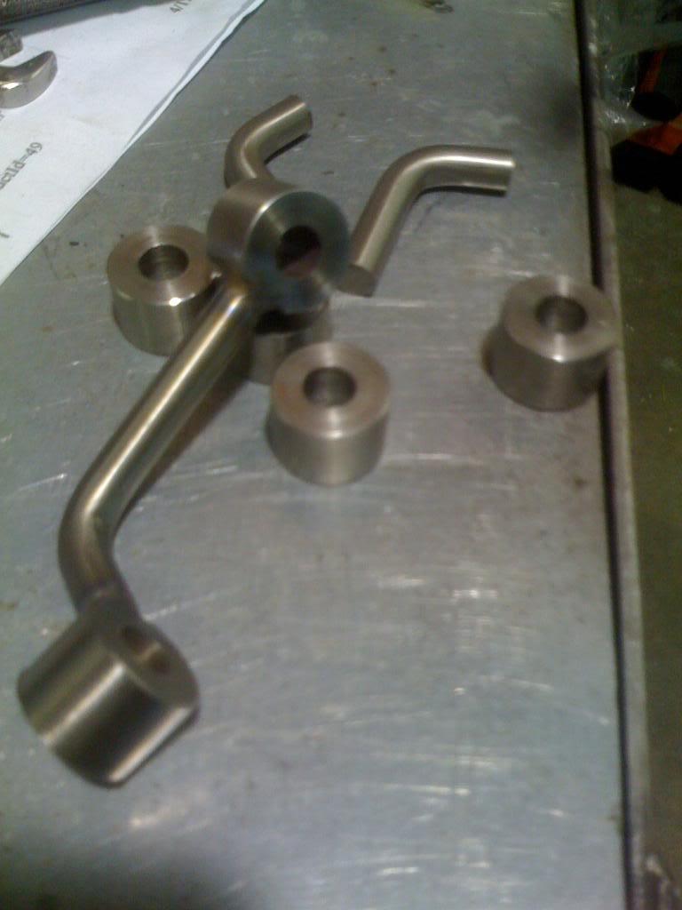
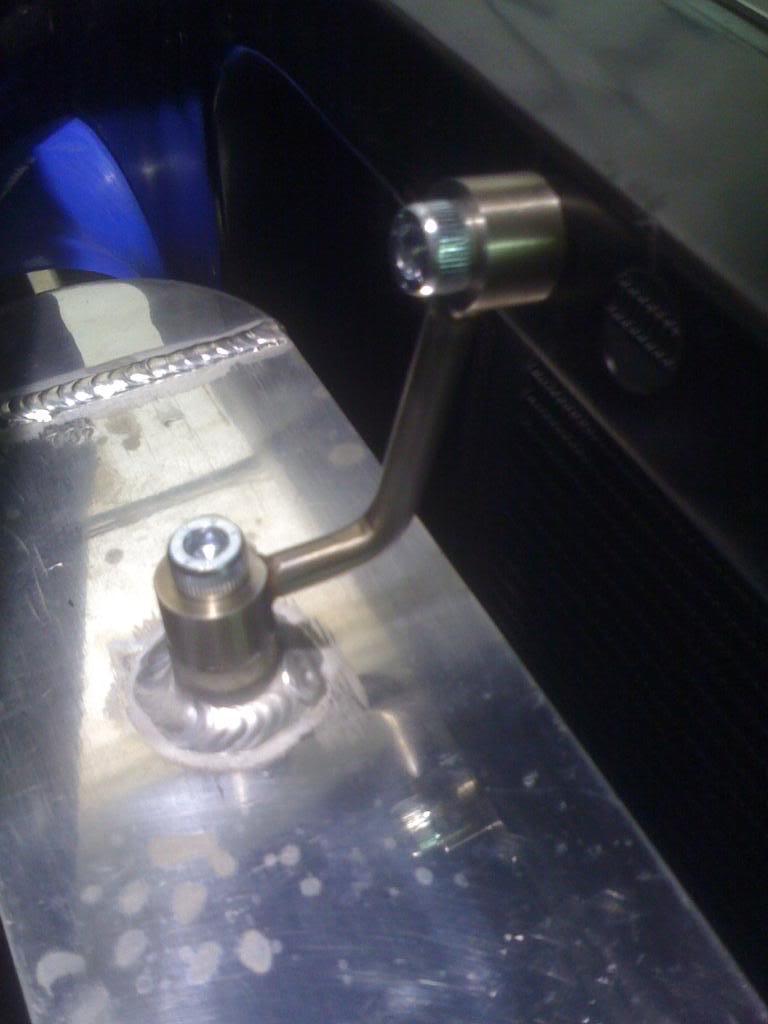
Forgot my camera, so excuse the iphone pics, but made some intercooler brackets today.
7/2/2009
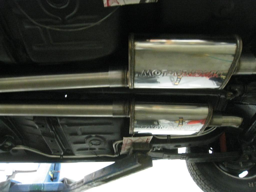
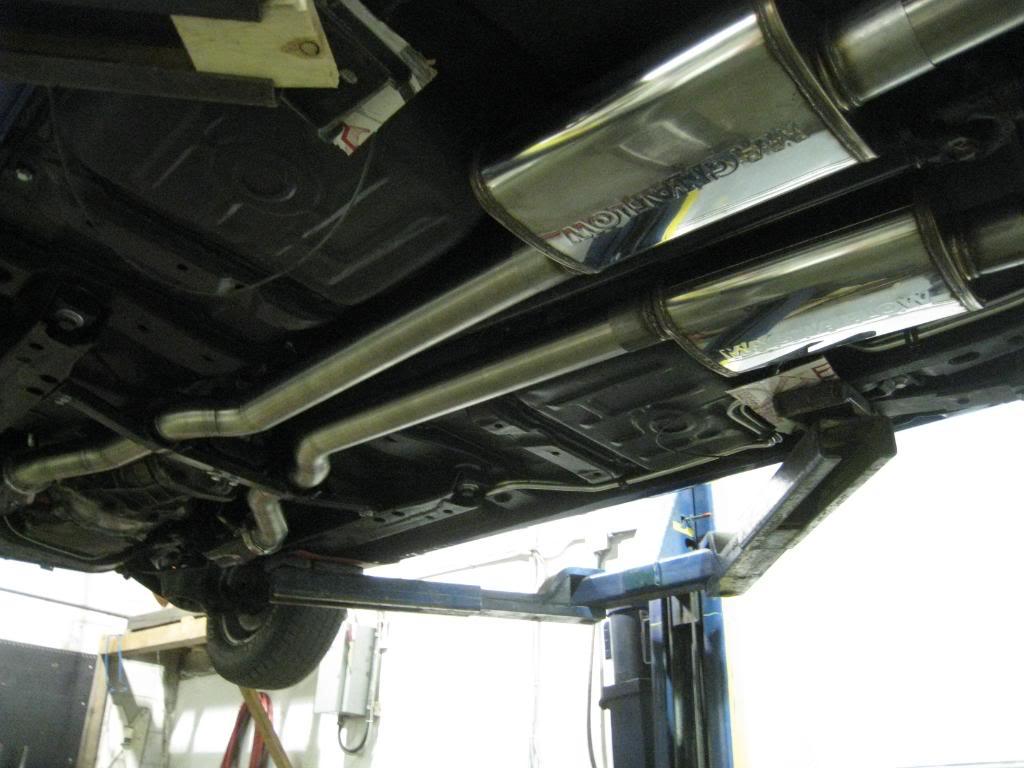
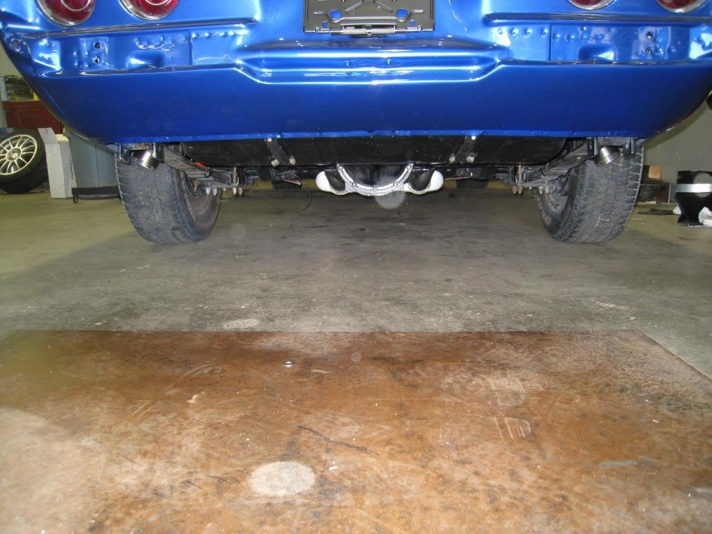
Got more exhaust done today. Still need to do the tailpipes and hangers, but I didn't like the over the counter hangars that were available at my parts store. I'm gonna make something up out of stainless that is a bit more presentable.
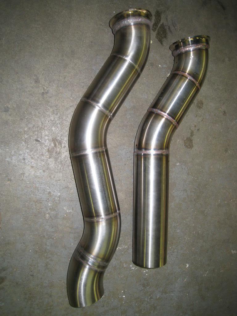
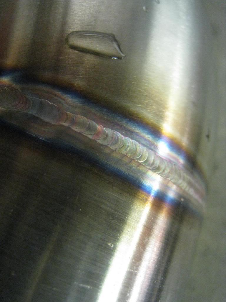
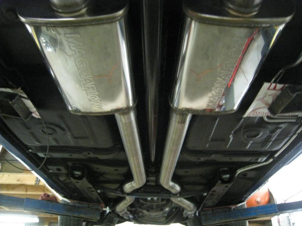
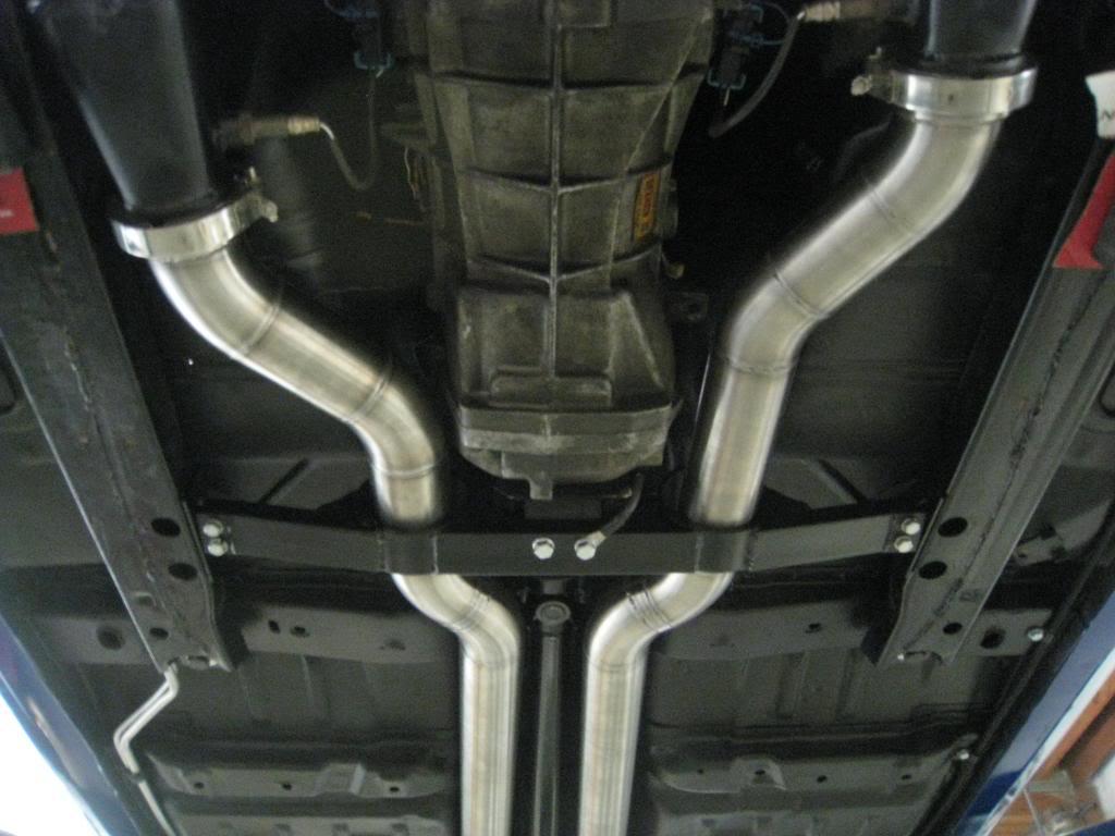
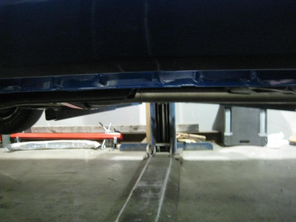
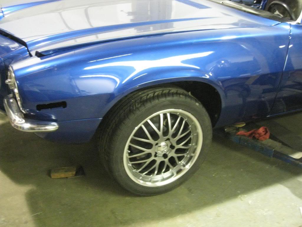
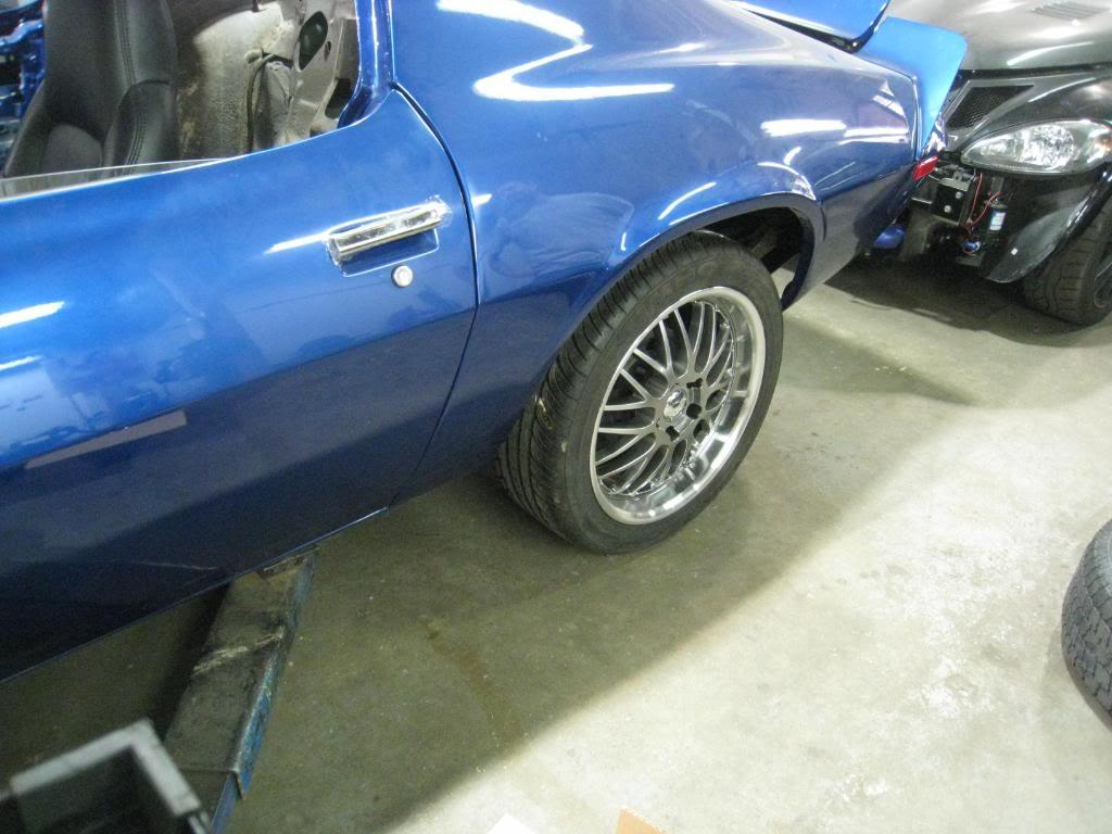
I borrowed this wheel from frojoe and set it into my wheelwell just to see... of course the car is sitting way too high.

7/8/2009
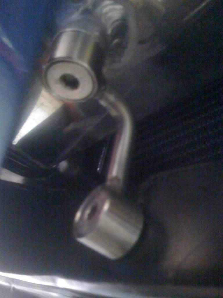
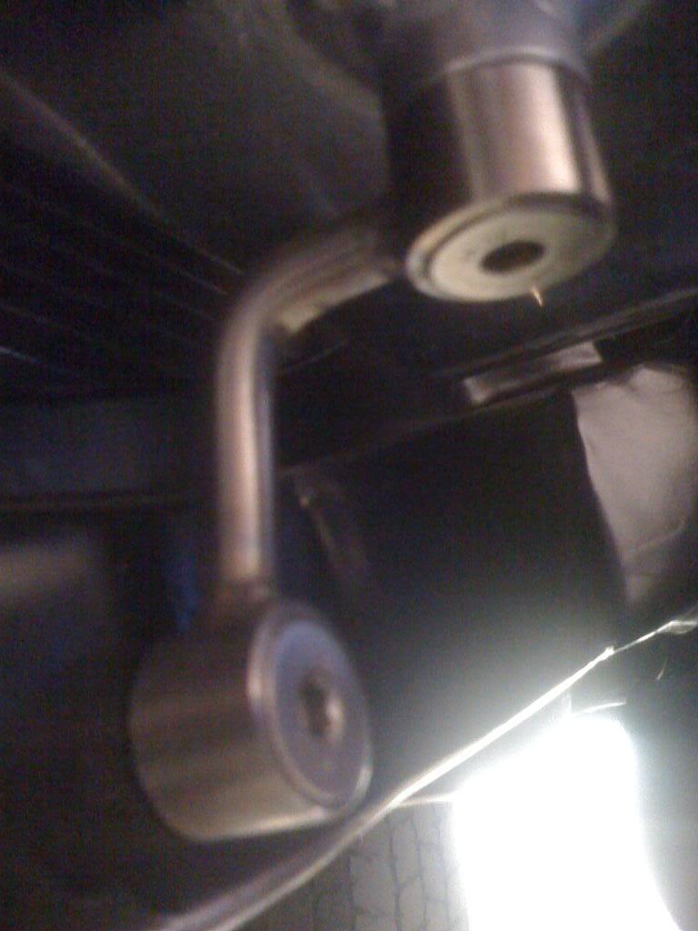
Finished the intercooler brackets today.
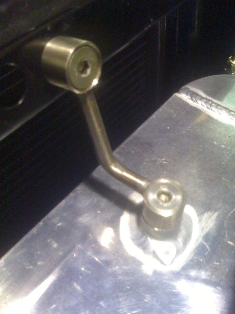
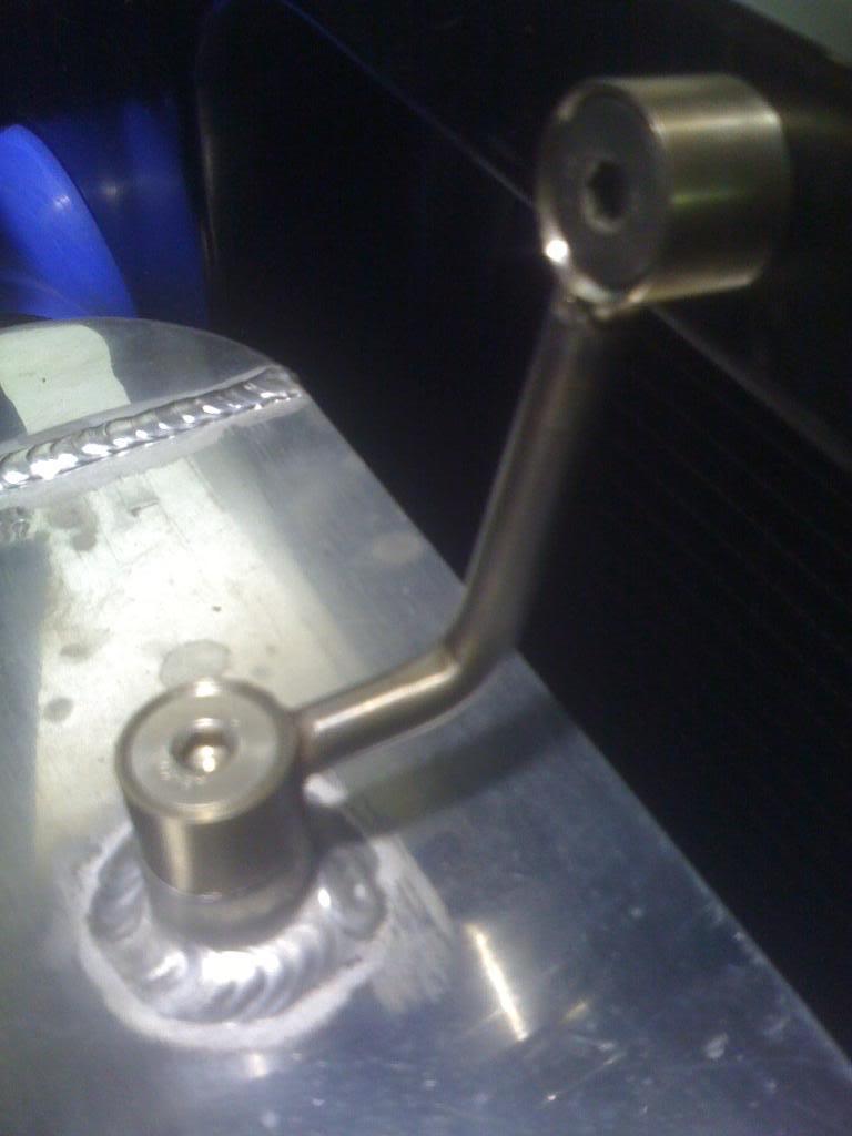
7/11/2009
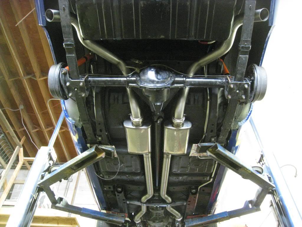
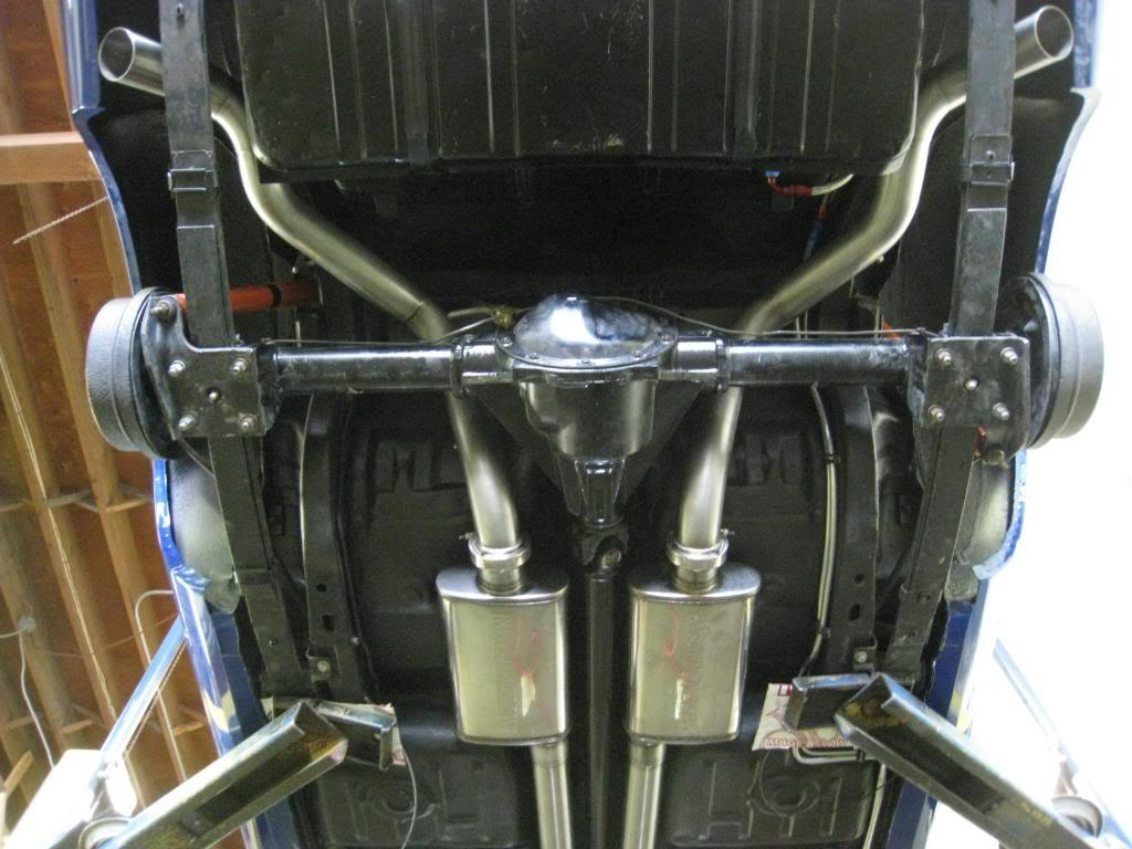
I finished my exhaust today. A huge thankyou goes out to Ryan Lore at Custom Metalcraft. Helped me out so much I can't thank him enough!
Here's what you get for 40 hours of work...
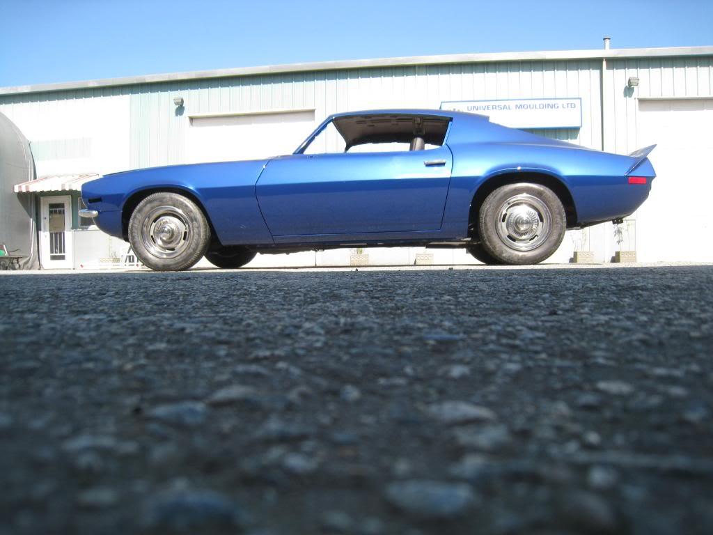

7/21/2009
Took a little break from the car after the exhaust work. Time to order more parts! So... In transit as I type this... QA1's coil overs with 550lb springs, Hotchkis rear sport leafspring kit, 3 way adjustable rear swaybar, new rear window mouldings, used front windsheild mouldings, moulding clips, and door panel clips. Hope to have a very productive weekend!
7/23/2009
Bought my wheels and tires!
Should see em next week...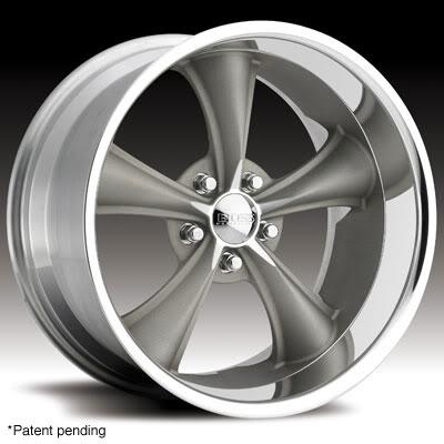
7/24/2009
Got my wheels today! tires next week...
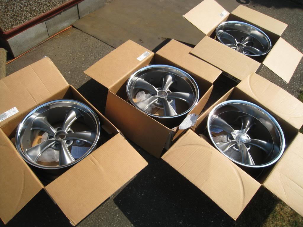
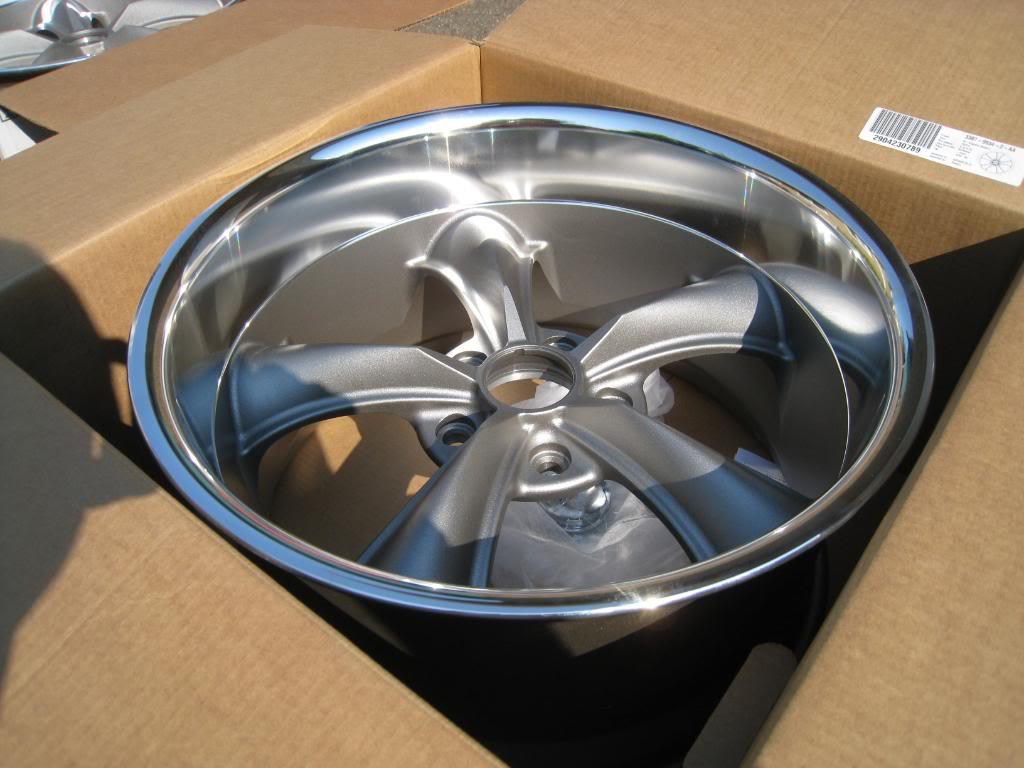
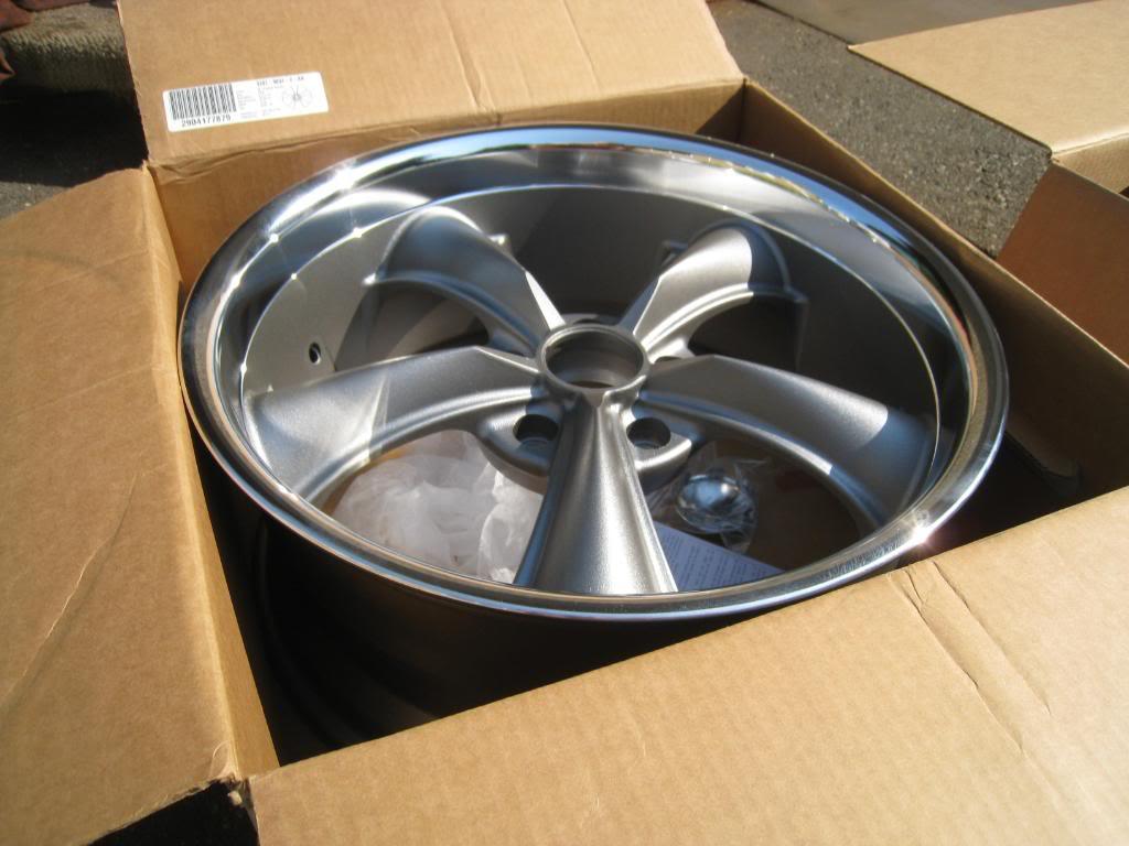
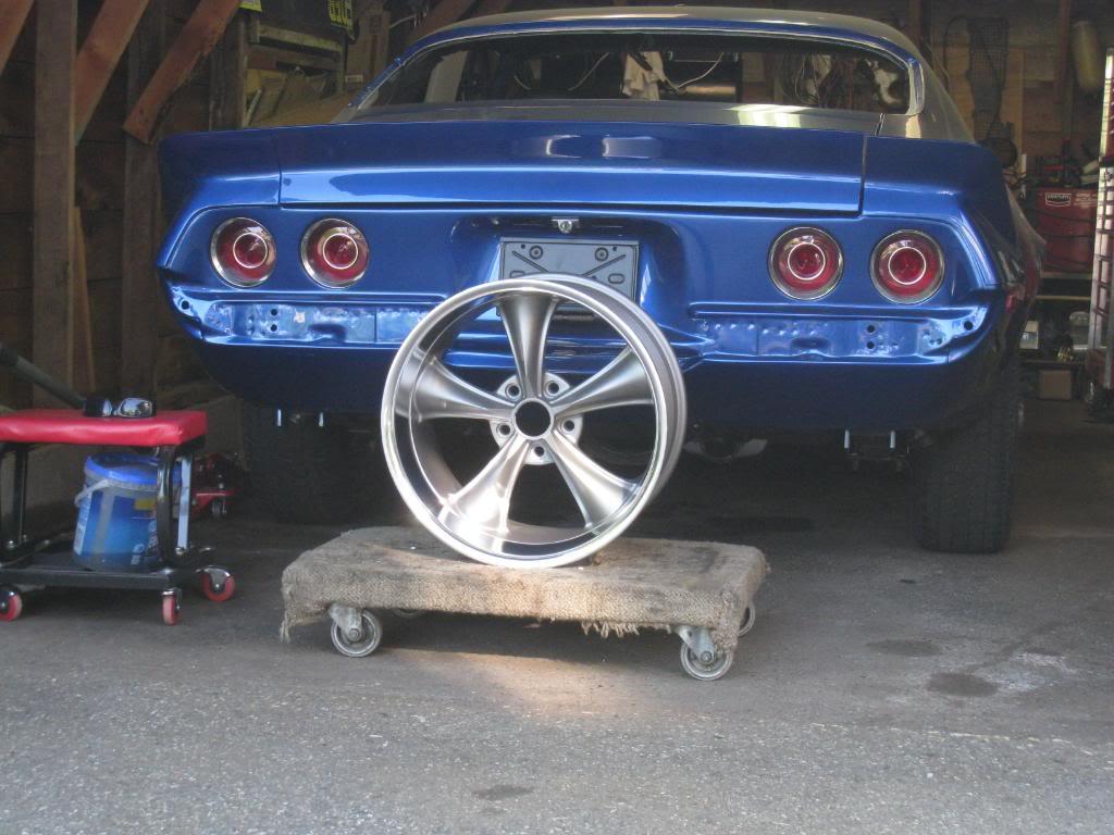
7/31/2009
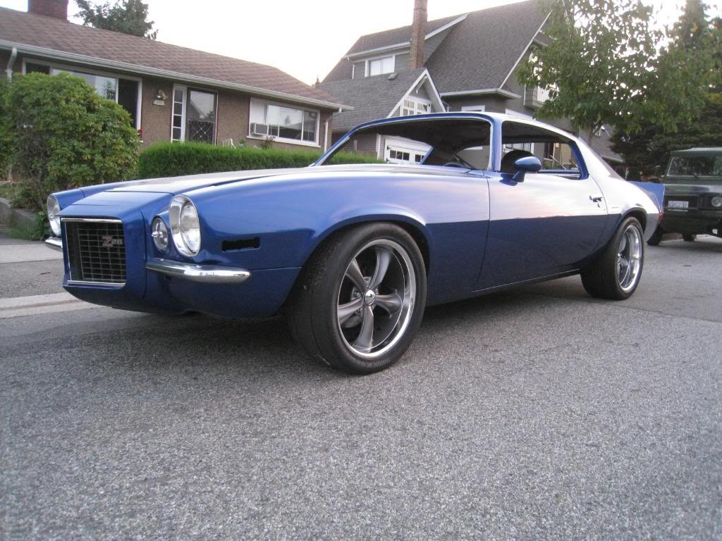
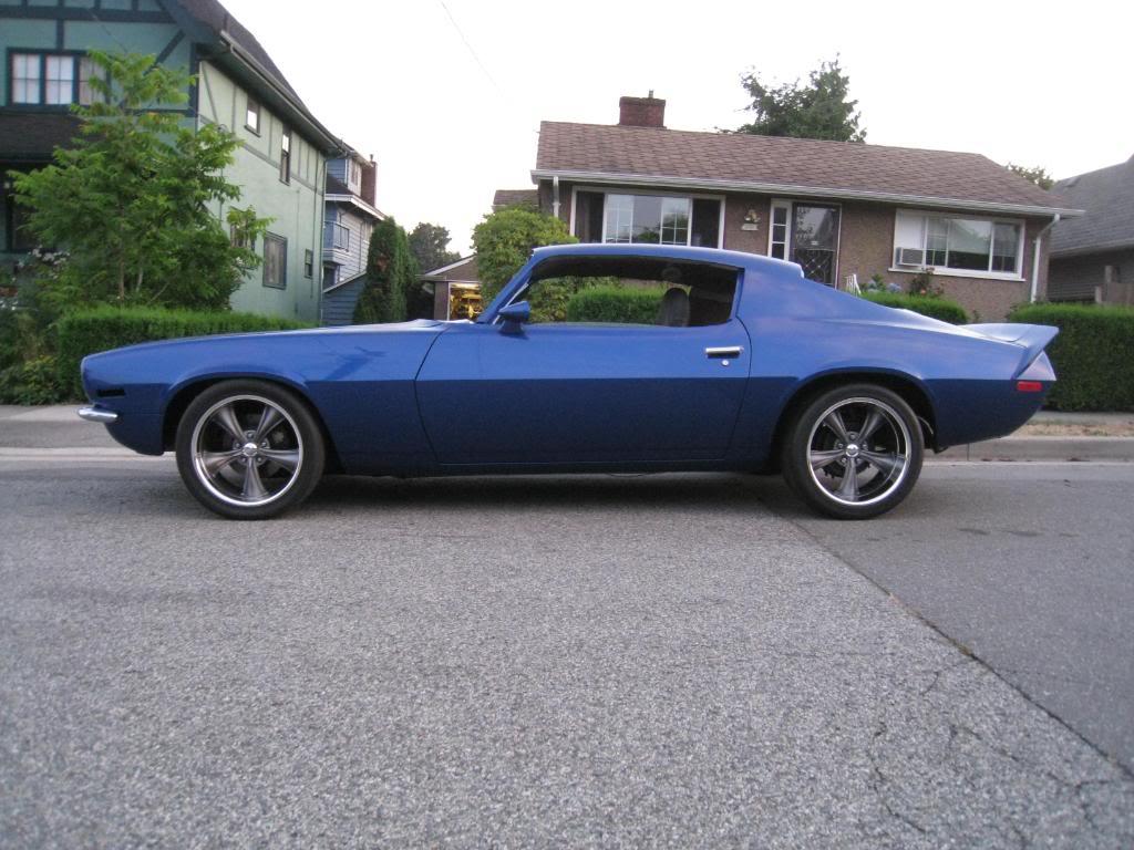
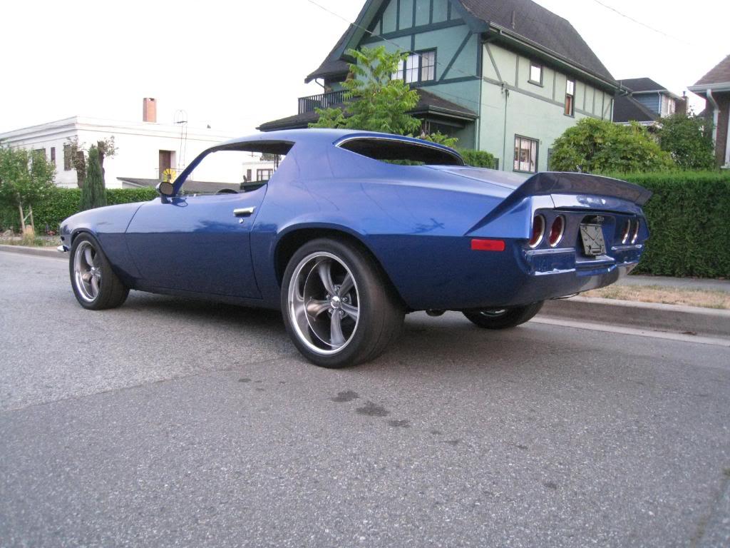
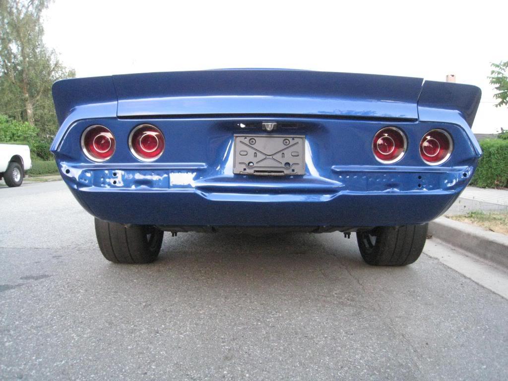
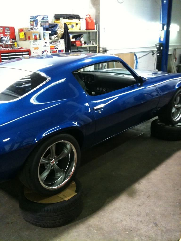
Installed my QA1's and new wheels. Just need to dial in the ride height.
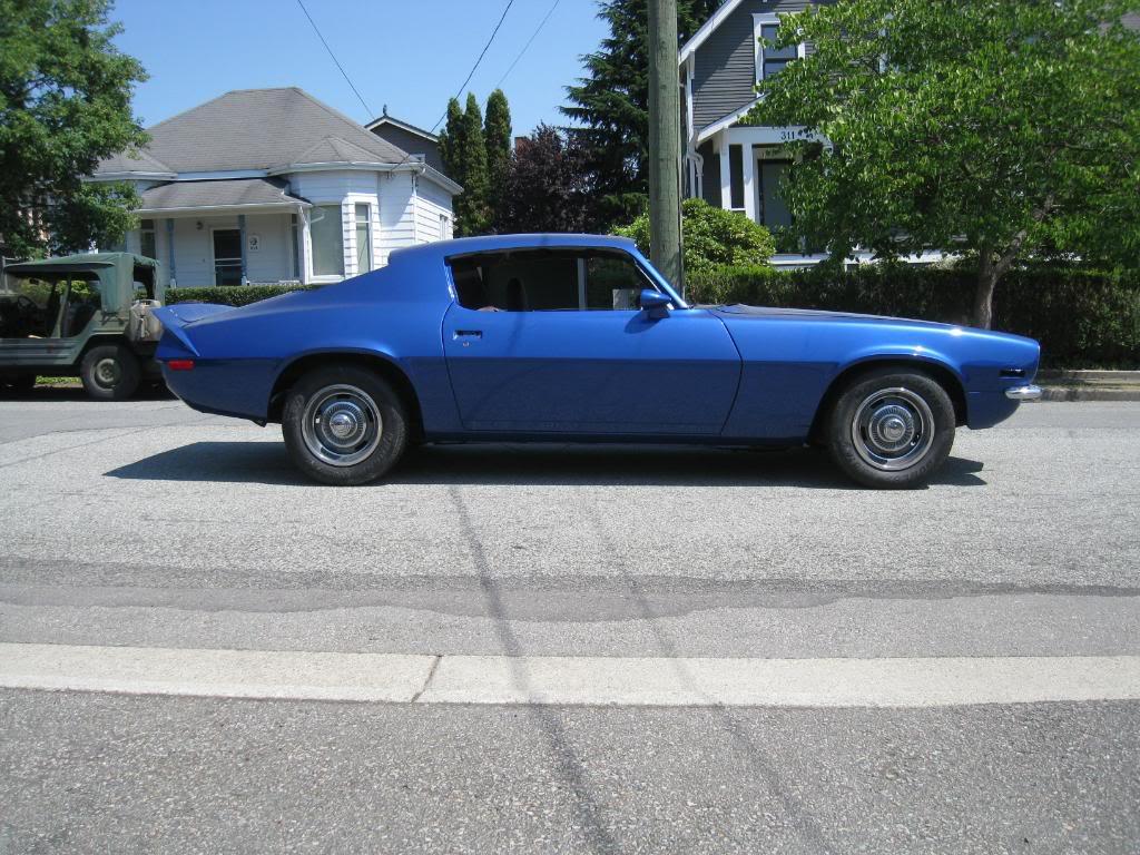
BEFORE
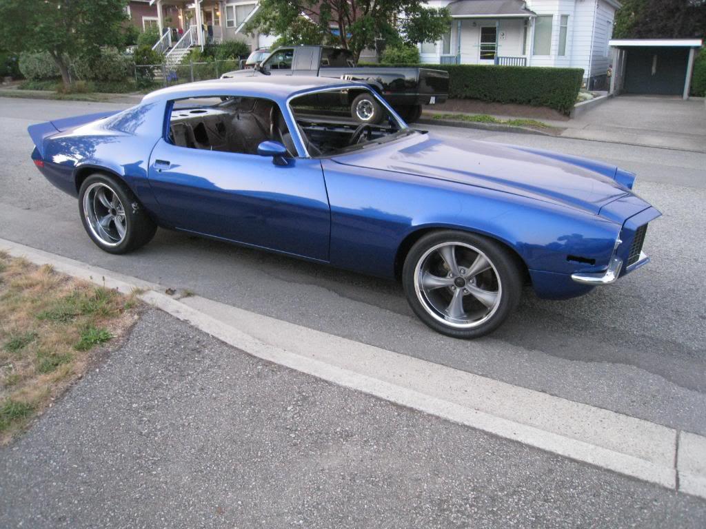
AFTER
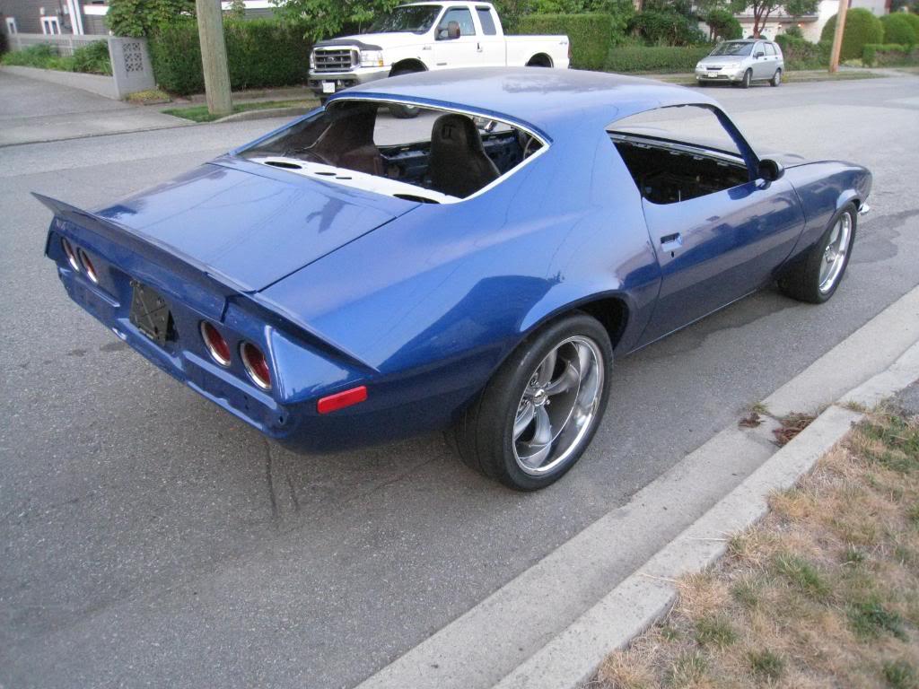
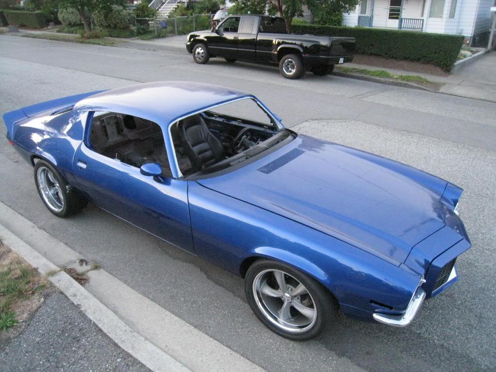
8/9/2009
I spoke to Hotchkis about the rear ride height, they said it will settle completley within 100 miles. The website says within 5 miles. Mark at Hotchkis suggested some lowering shims so I could get that extra 1/2" out of the back. DONE, on order. I will do a rough alignment in the front to see how the tire edge sets into the flare, but expect to raise the front at least 1/4"
I think that should get the car where I want it to sit. I still have the entire interior to install along with sound deadening so that extra weight should help settle the car a little more.
8/10/2009
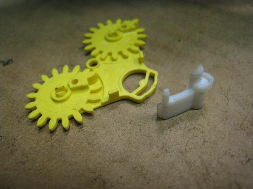
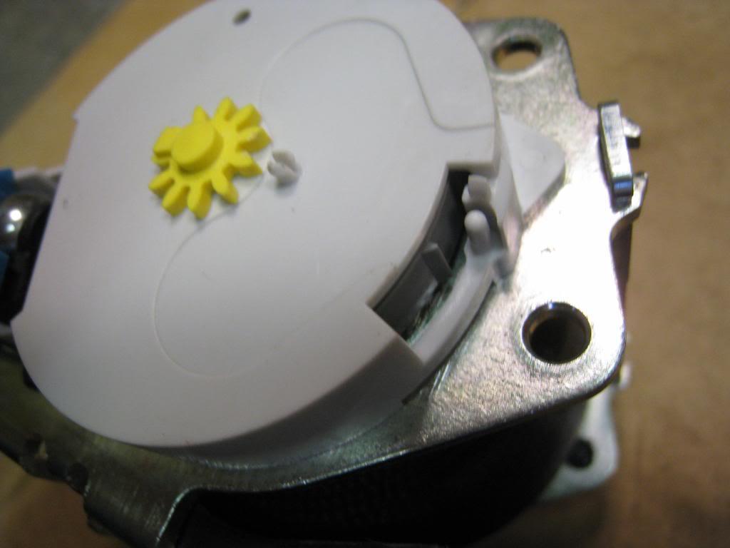
I decided to put modern seatbelts in the car. First I figured out where the retractor would go, and the shoulder pivot. Then re-enforced the areas with 1/4" flat bar. I put the shoulder pivot low enough that it will be in the sail panel instead of the headliner. The retractor will be behind the side panel. I just need to cut a slot in the panel for the belt to pass through.
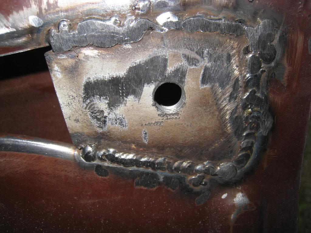
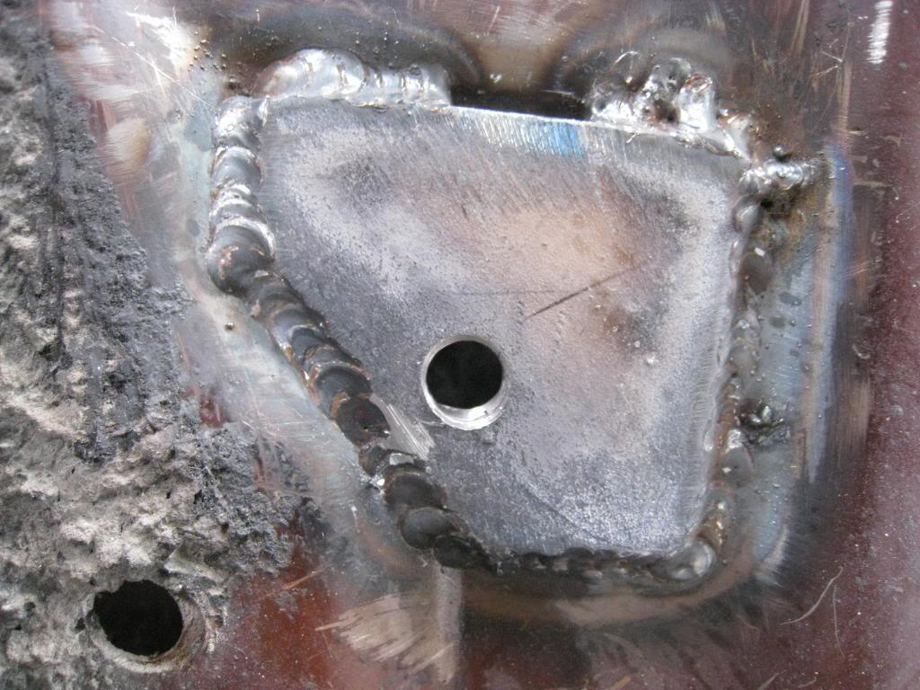
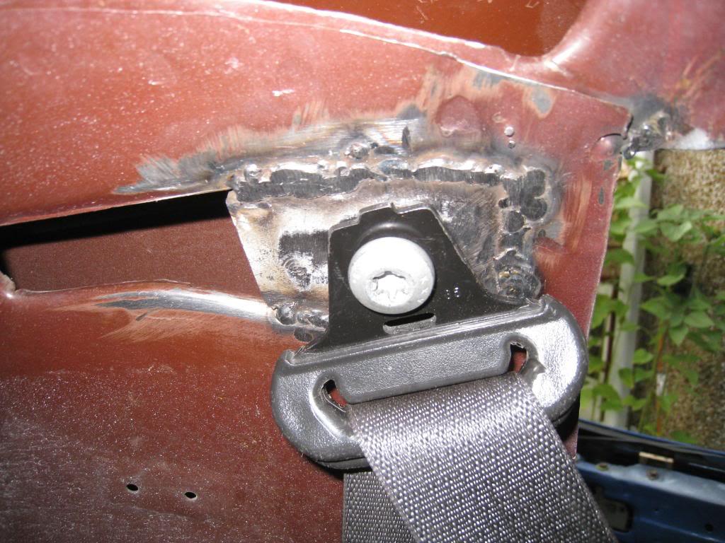
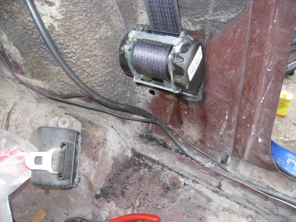
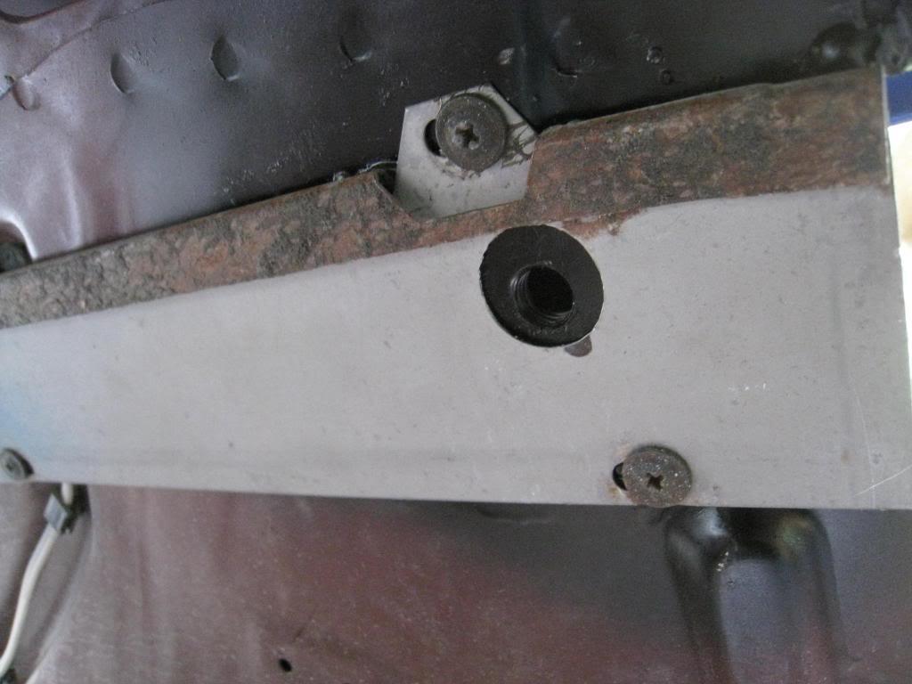
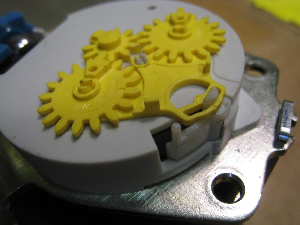
Just in case anyone else wants to do this mod, you have to remove the ratchet part from the retractor otherwise if you pull it all the way out, it will retract and jam. The cover to remove is the one that faces the front of the car. If you take of the wrong one the spring goes flying. Not good. Trust me.
8/30/2009
Things have slowed down on the build mainly because I have to rely on others. Not a dig there, just thats how it goes. I decided to have my headliner installed by a pro to avoid wrinkles etc. and guess what? Not only did I still GET wrinkles, I got an extra hole for a mirror that mounts on my windshield. F*%&. Guy says he'll fix it. Oh well. just another test of my seemingly endless patience. I started to install my soundproofing today, and will take some pics and add them tomorrow.
9/5/2009
Once again I spent way too much time on another detail of my car. I spent a lot of time researching for new gauges for my LS2 conversion, and I just didn't really like any of the options available that much. I liked the look of the stock guages, but needed something newer. So I figured, why not put new guts into the old cluster? Easy right? Well, 40 hours or so later, I'm happy with the result. Here's a bunch of pics.
First just to see if the sizes would work, I downloaded images of the gauge faces, scaled them to full size, and set them in their holes.
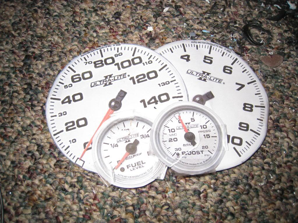
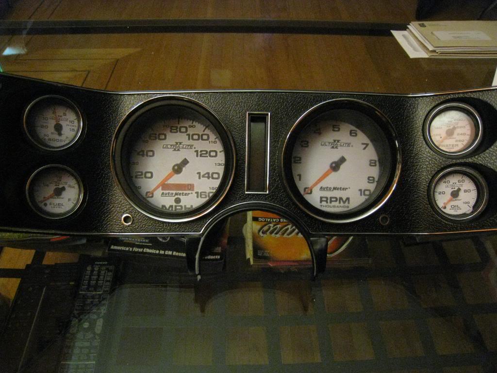
So far so good. Then I bought my gauges, decided which ones went in which holes, and then built up the courage to dis-assemble a bunch of VERY EXPENSIVE gauges.
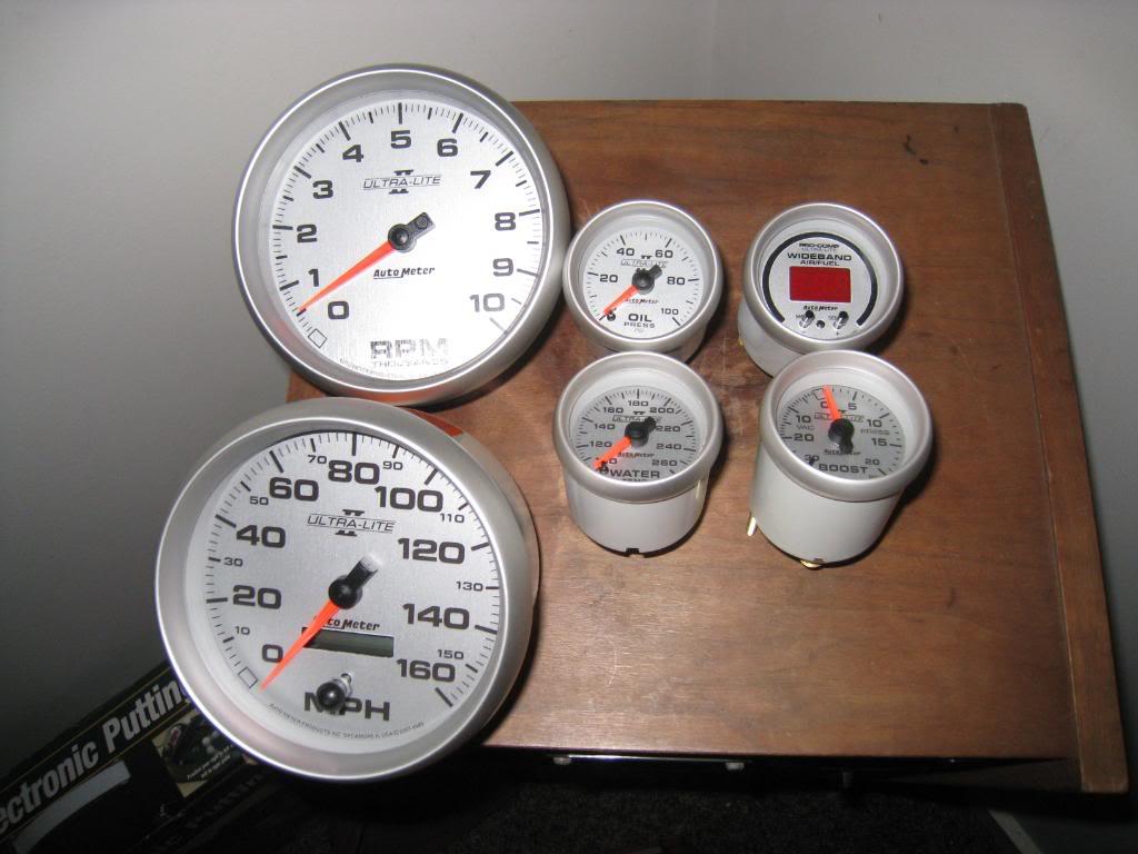
I peeled the bezel lips back with a thin bladed screwdriver like a can opener and took them apart. (I started with the least expesive gauge first, just in case)
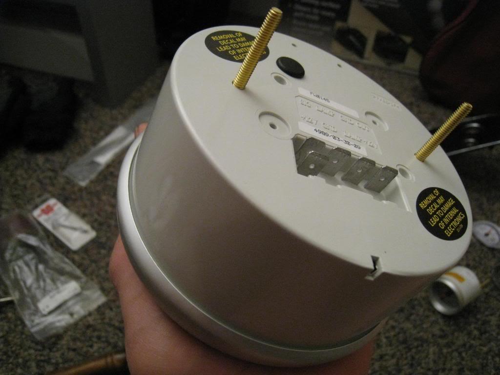
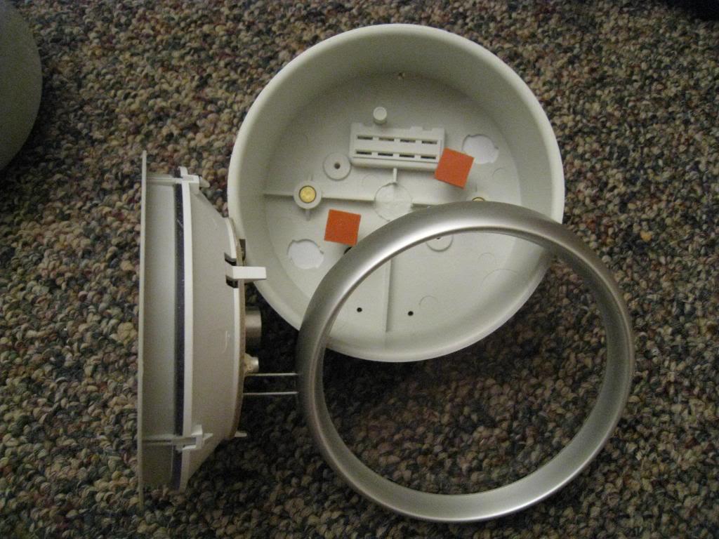
The small gauges, other than the boost guage, rely on the bezels to locate the faces and internals. So when you pull off the lenses the guts want to fall out. What I did was plug in thewiring harnesses to hold the guts in from the back, then held the wires back a little and put a very fine bead of black silicone around the edge of the face of the gauge. This does 2 things, it holds the face into its position and prevents light from bleeding around to the front of the lense(important on back lit gauges)
The stock Camaro gauge lense assembly has a raised ring on the backside which locates the 'buckets' of the new gauges in just the right spot. *I did have to trim the outer edges of a couple of buckets for proper fit, plus the wideband needed the ring sanded down to be even all the way around so the face would sit perfectly flat.
When I was happy with the location of the gauges, I 'tacked' them in place with a little ZAP (crazy glue) then used my trusty hot glue gun to finish glue them in.
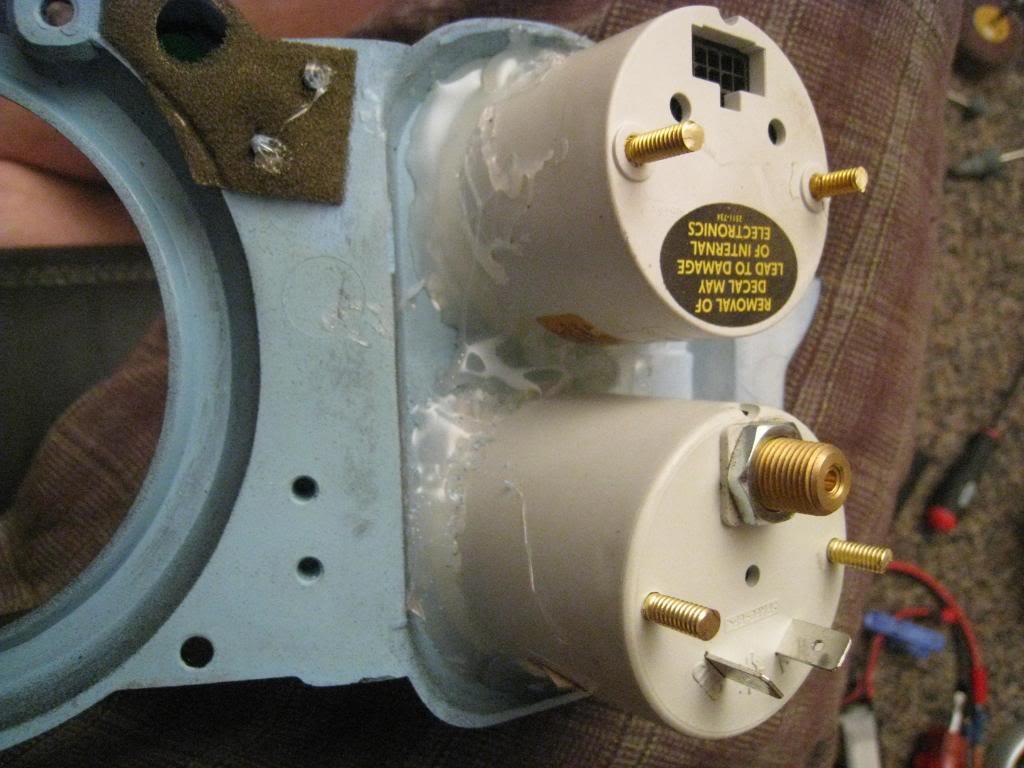
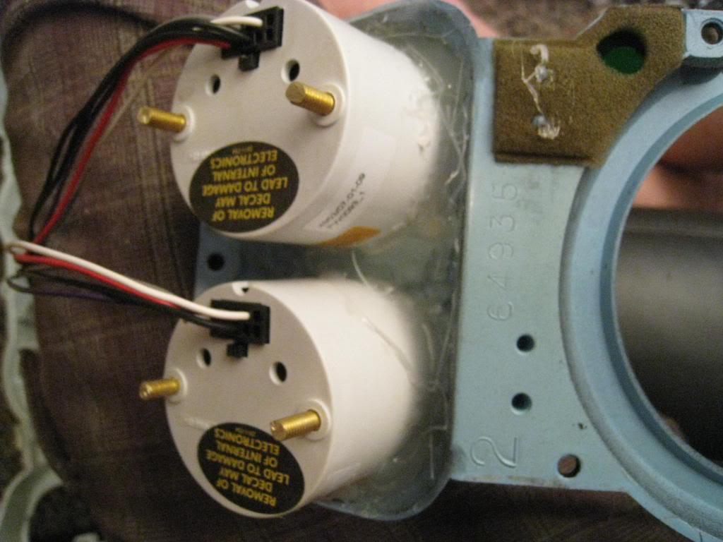
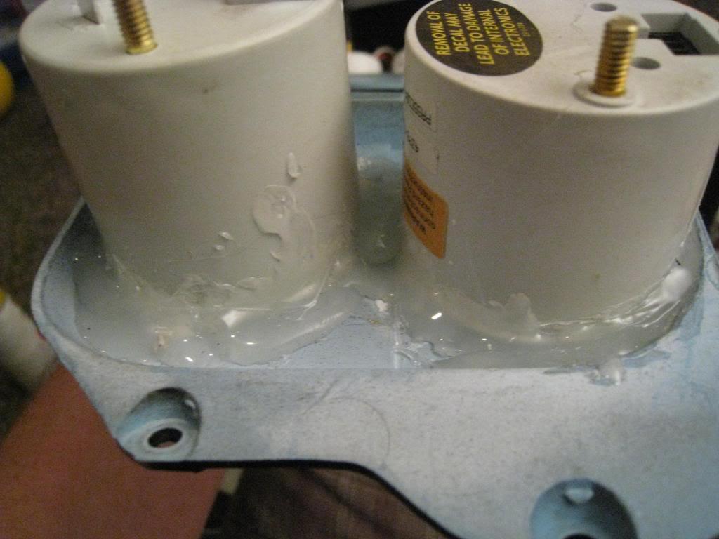
I then cut the back housing to accept the new small gauges.
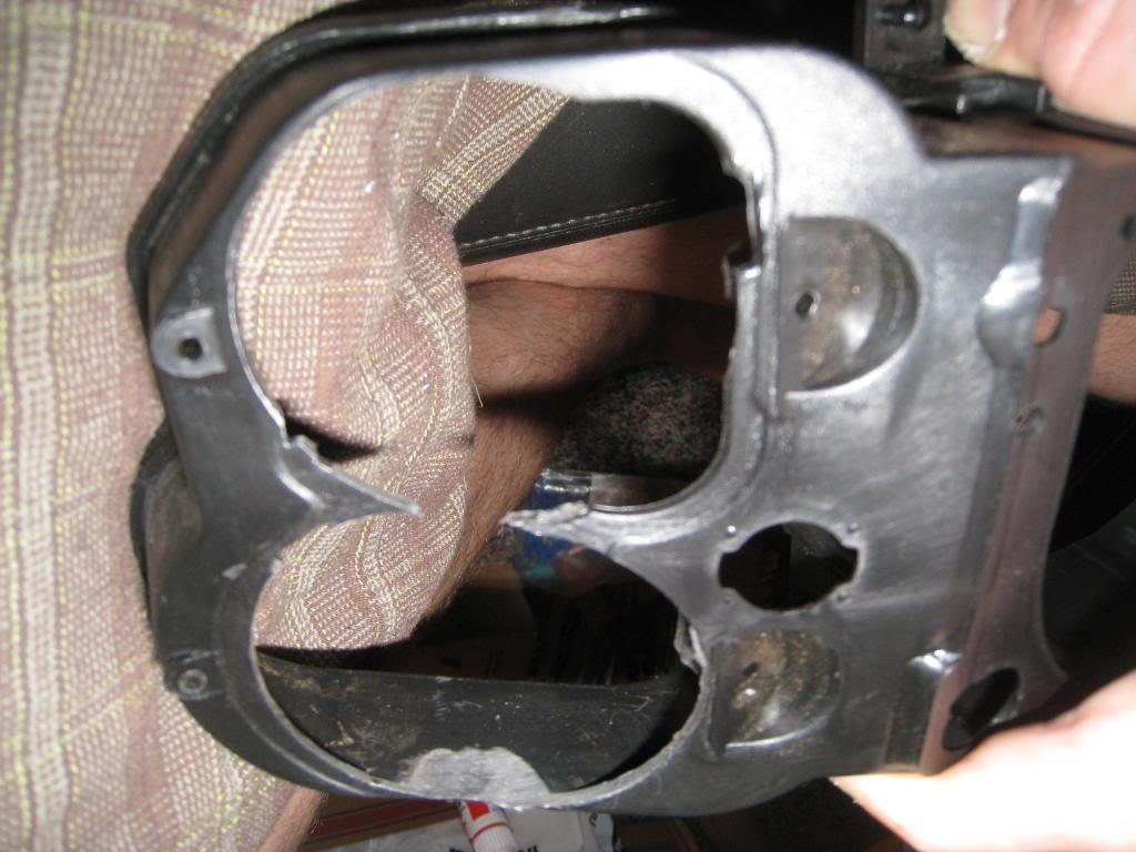
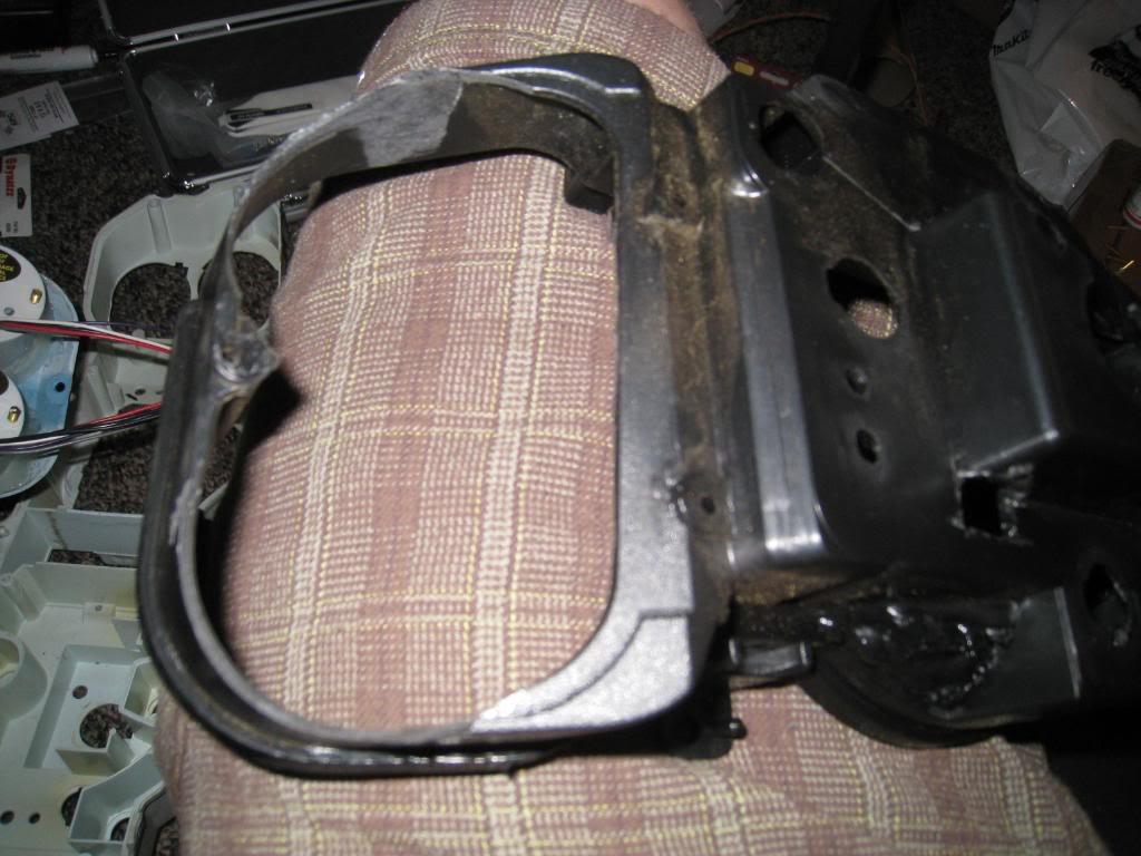
Now that they fit their holes I cut down the studs so they would be long enough to still use, but not so long as to make assembly difficult.(because of the angle of the gauges the studs make it tricky to put the 2 halves together.
The BIG gauges. I found that when the guts are pulled completely from their housings the Autometer 5" in dash gauges are just about the right size to mount in the original holes. You do need to do extensive 'lego welding*' to make the speedo fit. ((*lego welding* as a child over a number of xmas's got lego's / got mechano set / got woodburning kit .....))
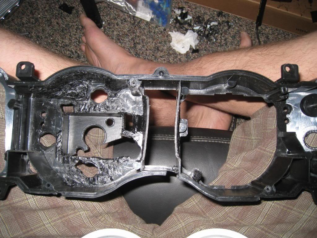
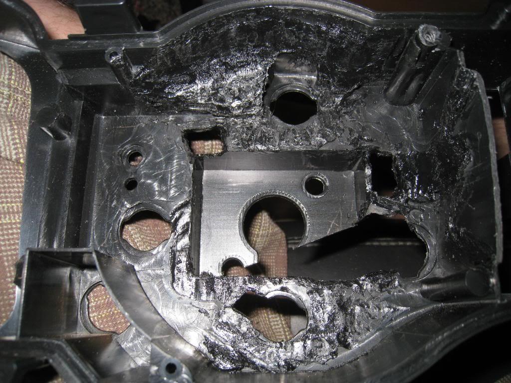
Next you set them in place and bolt the 2 halves together
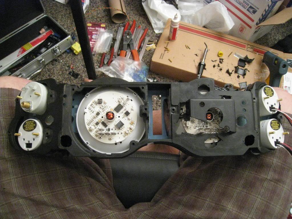
The big gauges are held in place by their lips being pinched by the 2 halves of the factory cluster. Perfect!
I wired things up then built straps out of aluminum for the 2" guages and used the stock holes for mounting the original gauges to hold them in place. (this may be overkill as the glue is really good. If you do this step, however, be sure the straps have no pressure on them. Bend them to fit. If they have pressure on them in any direction they will distort things, and possibly pull the gauges off of their spots.)
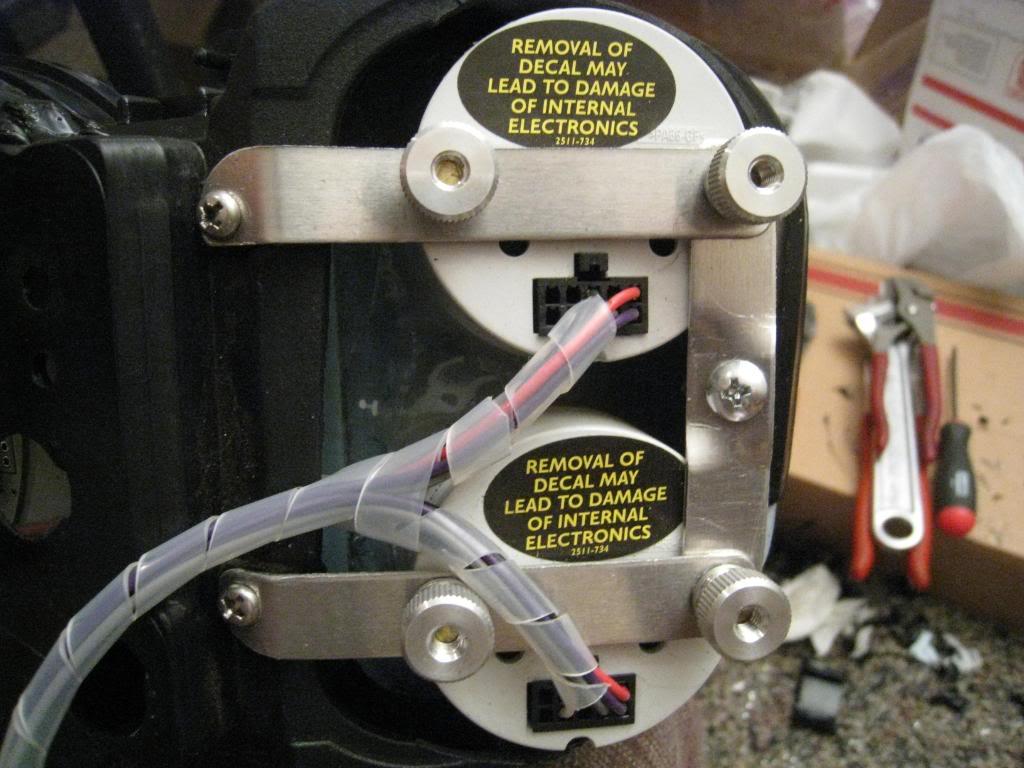
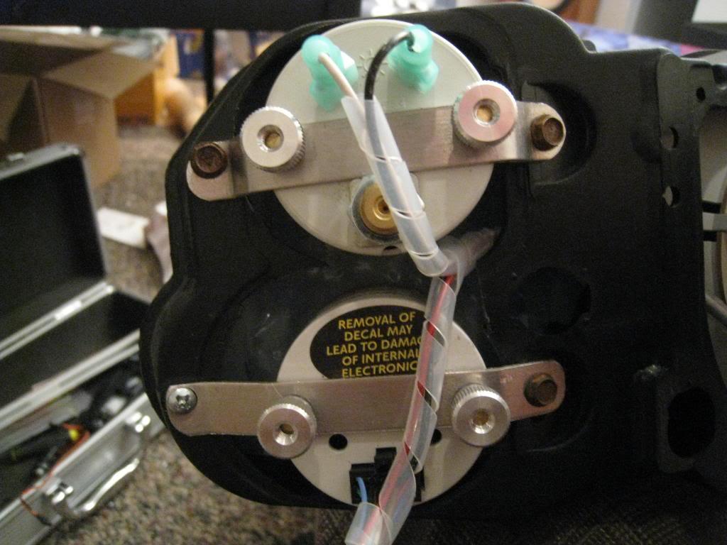
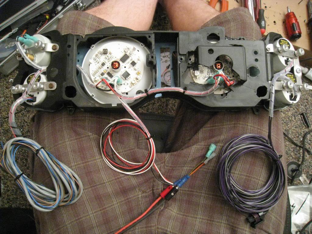
And here you have it. From paper face cut outs to the real thing in around 40 hours or so.
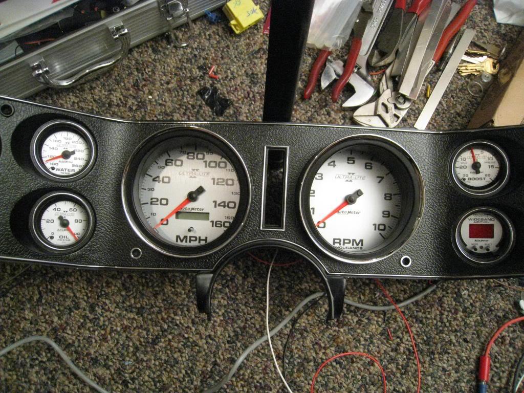
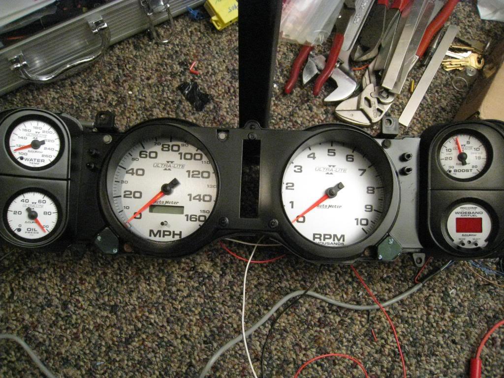
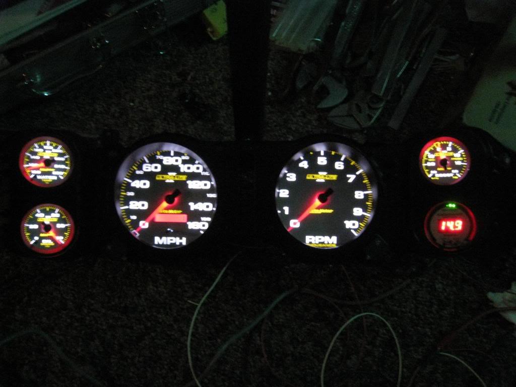
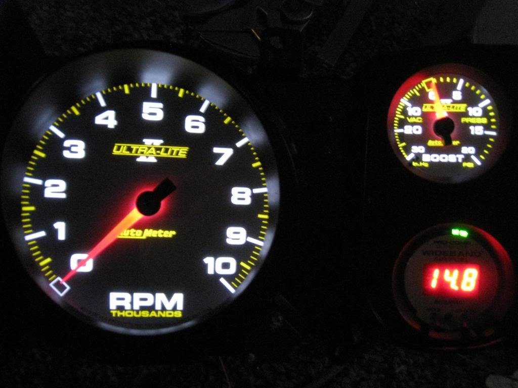
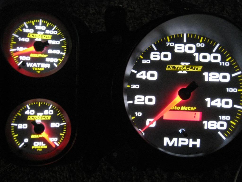
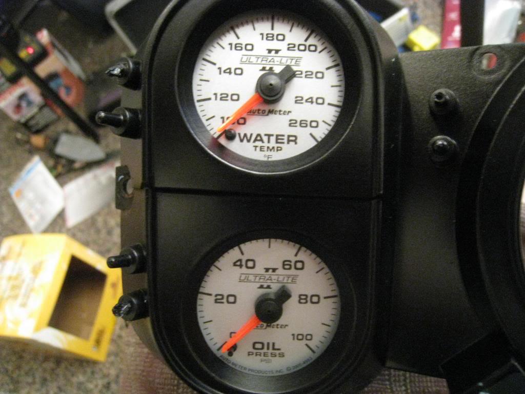
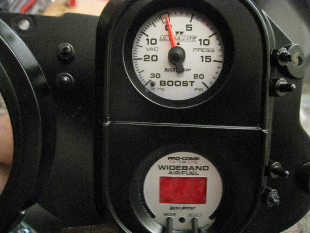
I ordered a new lense for it and as soon as I get it I will finish the cluster including holes for the speedo button and wideband buttons.
10/3/2009
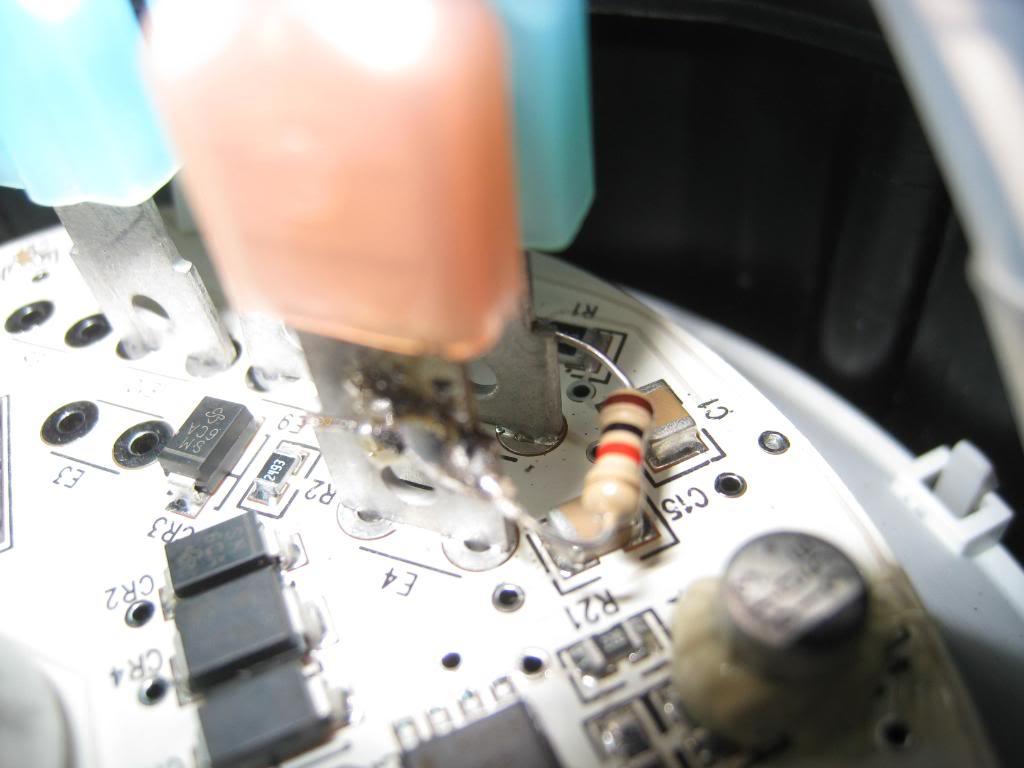
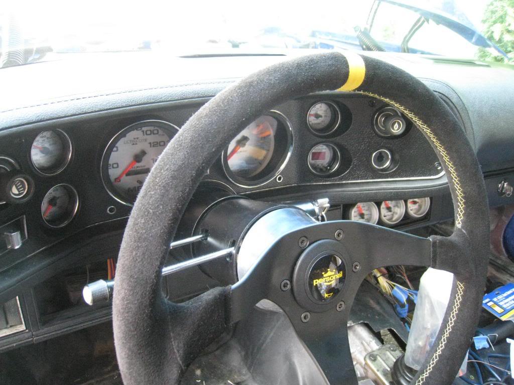
Finally got the guages into the car. I had to extend the push buttons on the AFR gauge and the speedo. I used some carbon fiber rod used for RC helicopter boom struts, and cut it with a dremel. To attatch it I used shrink tubing for wiring. No glue needed. Worked great! I also had to put a 1k ohm resistor between the tach input lead and the 12v+ input lead in order to get the LS2 to deliver a tach signal.
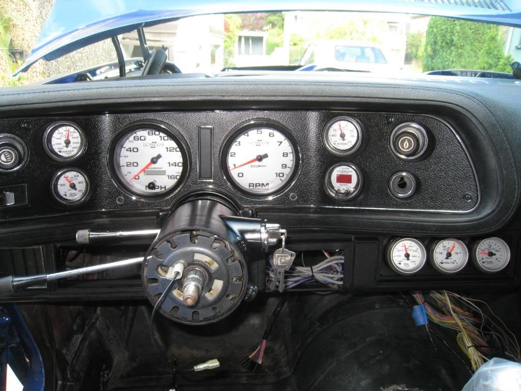
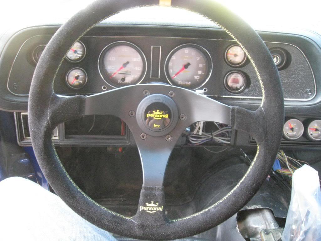
11/14/2009
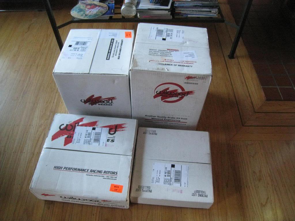
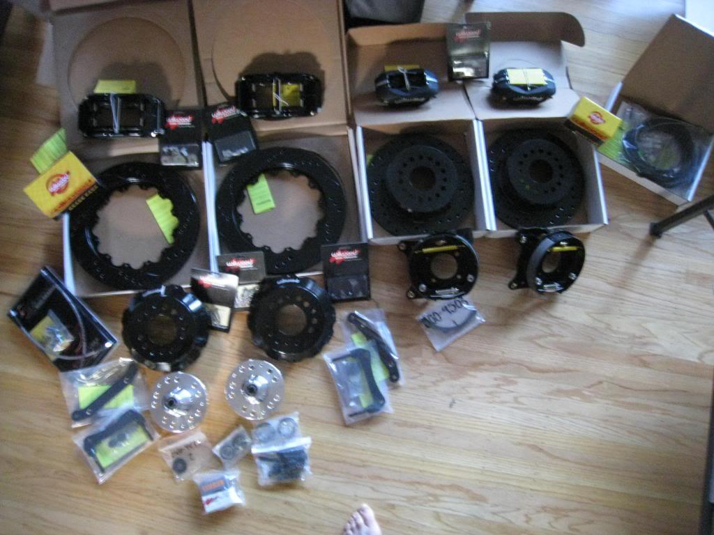
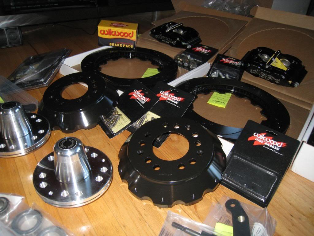
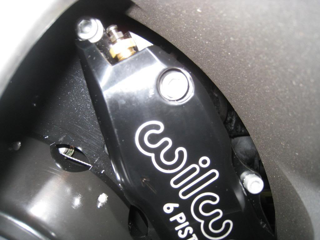
My long awaited brake setup arrived! 14" Wilwoods with 6 piston calipers for the front and 12" with 4 piston calipers for the rear.
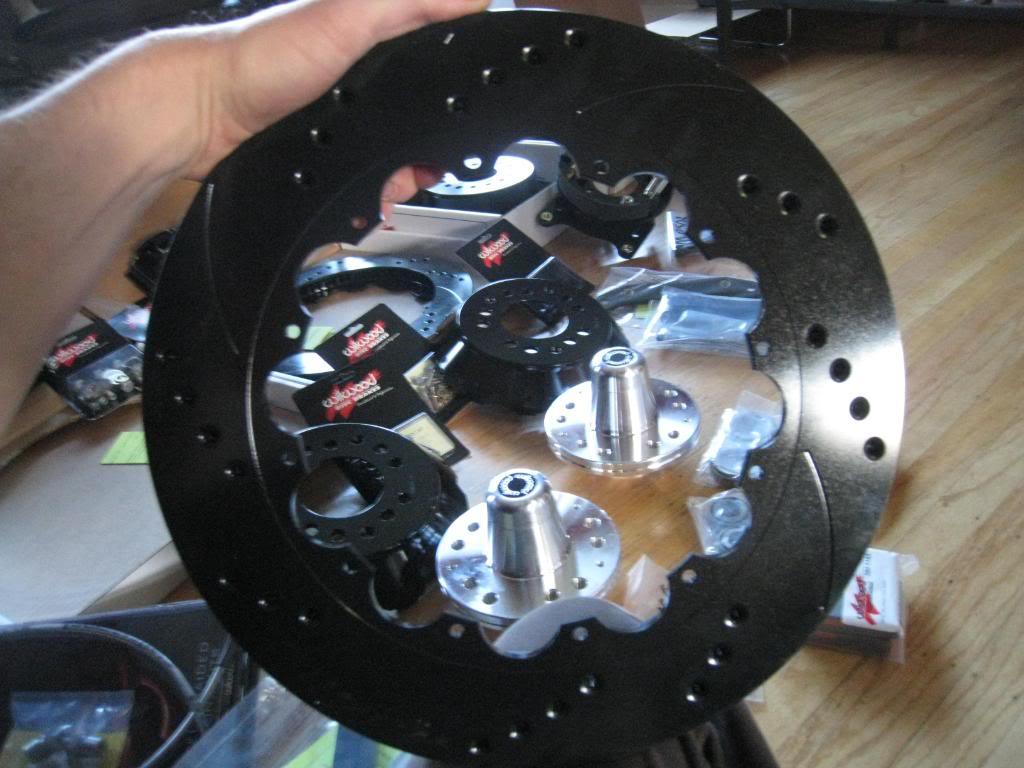
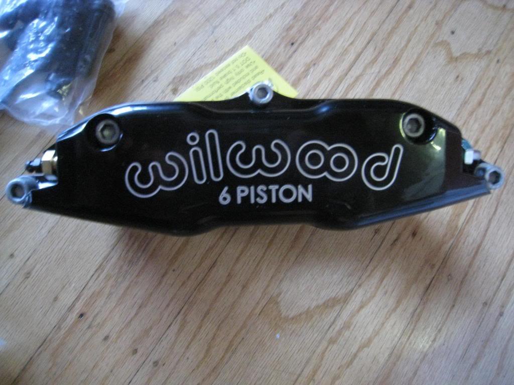
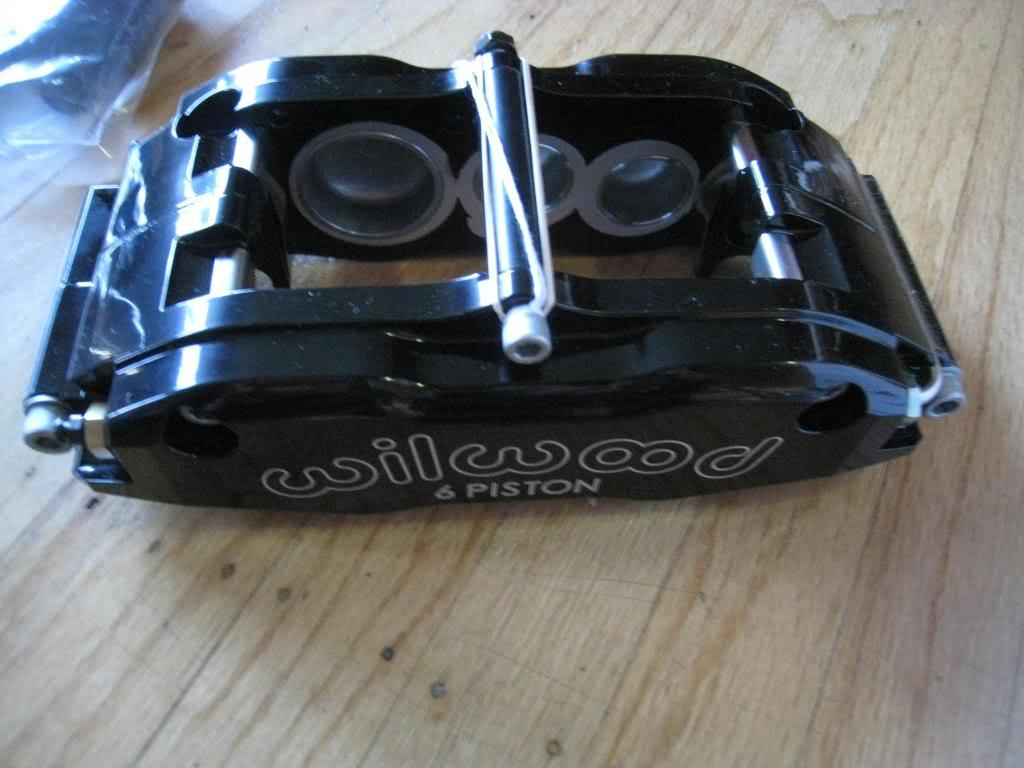
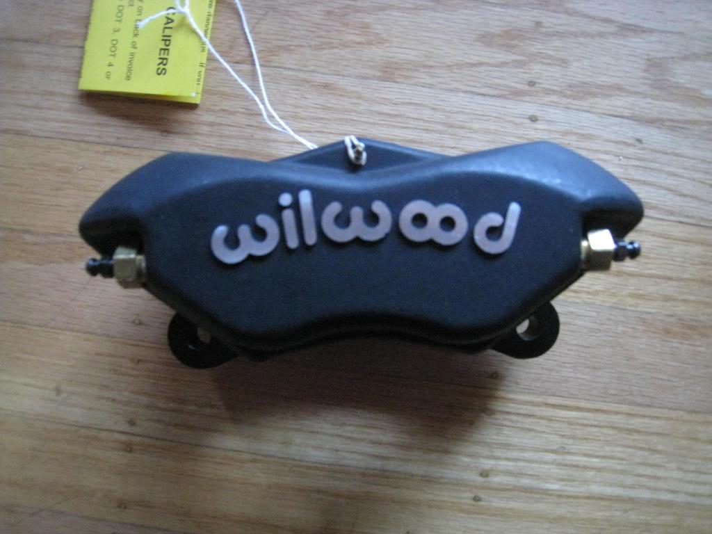
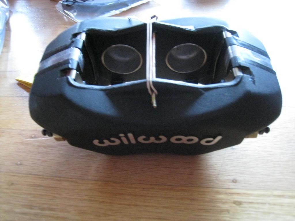
11/15/2009
Started the install. Things were going well. Had the spindle all cut, trimmed, drilled, tapped, countersunk, painted, bracket bolted on, then found that the previous owner had upgraded the brakes to 79 or newer spindles. They have bigger outer bearings so all that work was for nothing. Thankyou craigslist! Posted a wanted ad for 70 to 78 spindles and got a response within hours $40. Oh well, guess it was a practice spindle!
old brakes
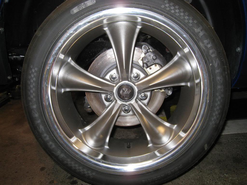
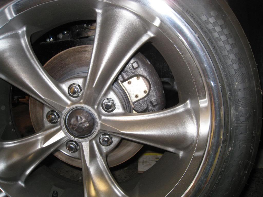
new hub and bracket

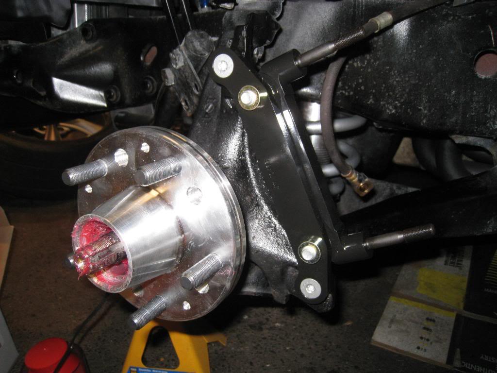
11/17/2009
Got the replacement spindles and got one side together. Still need to do the brake hose.
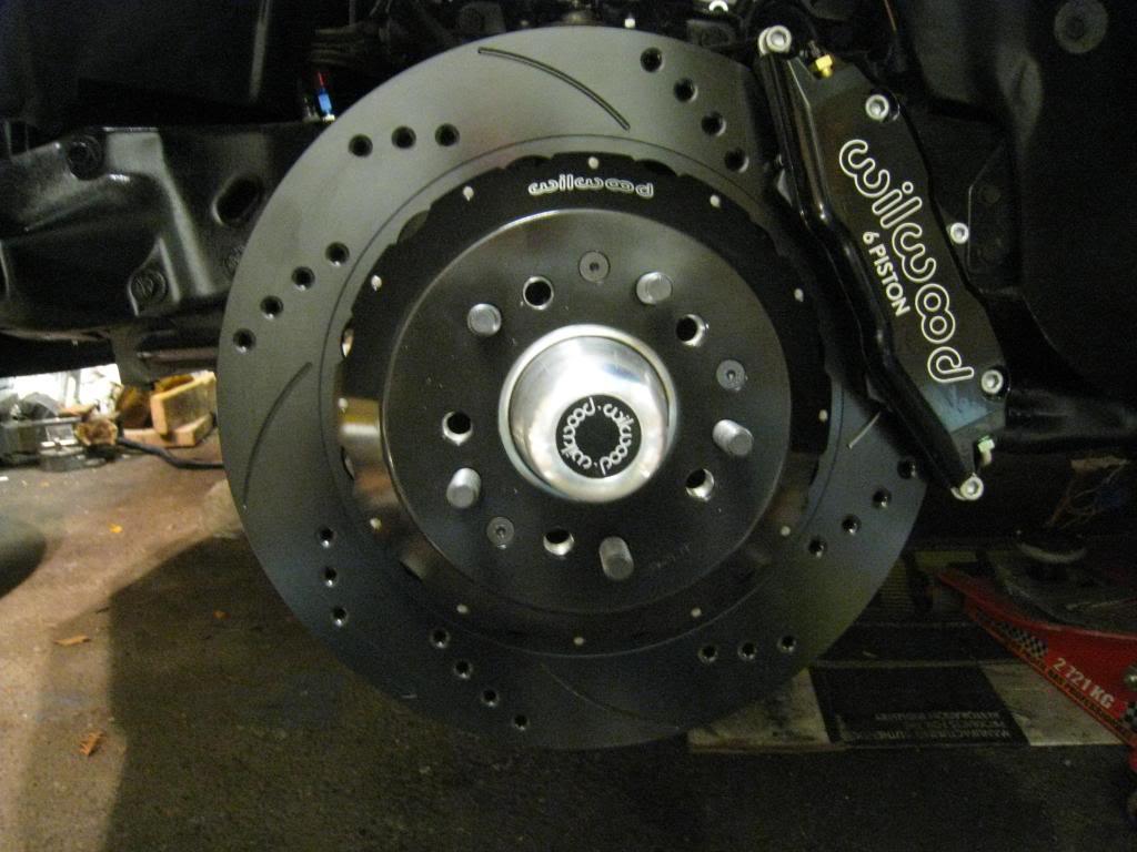

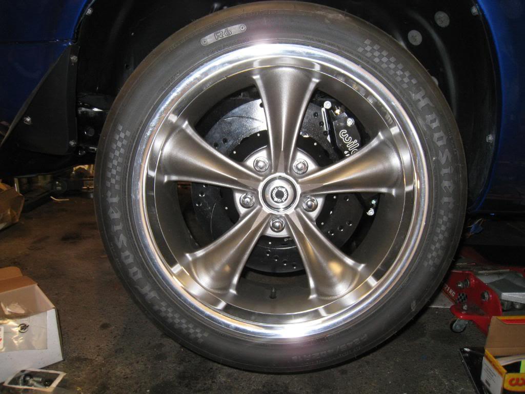
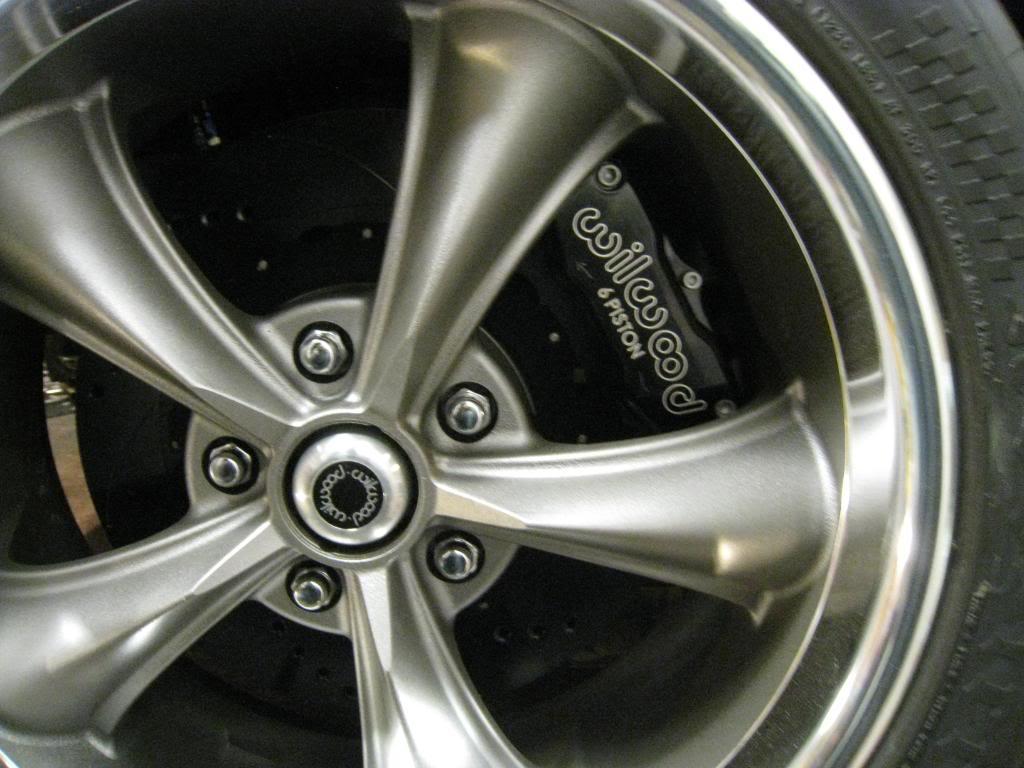
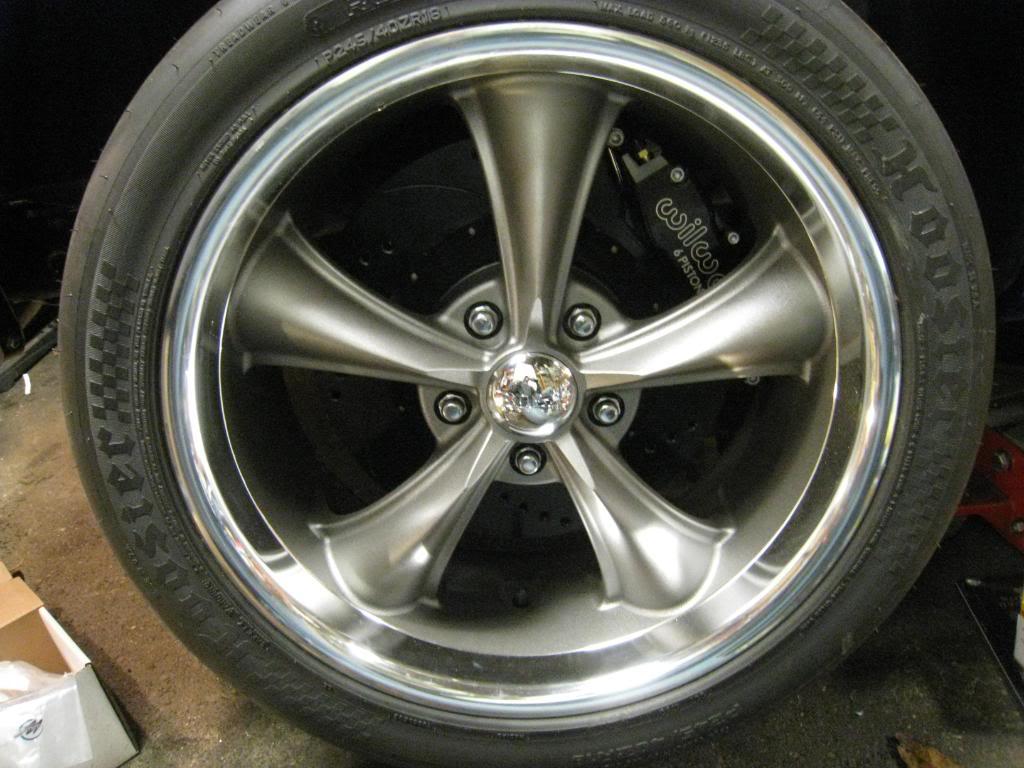
11/20/2009
I am using a 1 1/16 bore master cylinder (manual brakes). It may be too big. I will report back on that after I drive it. It will be on the road this spring. Should be ready sooner, but the weather will make me wait...

1/9/2010
Got back into the garage today. Finished the front brakes. Pulled the rear diff cover off and pulled one side of the rear brakes apart. More on that tomorrow.
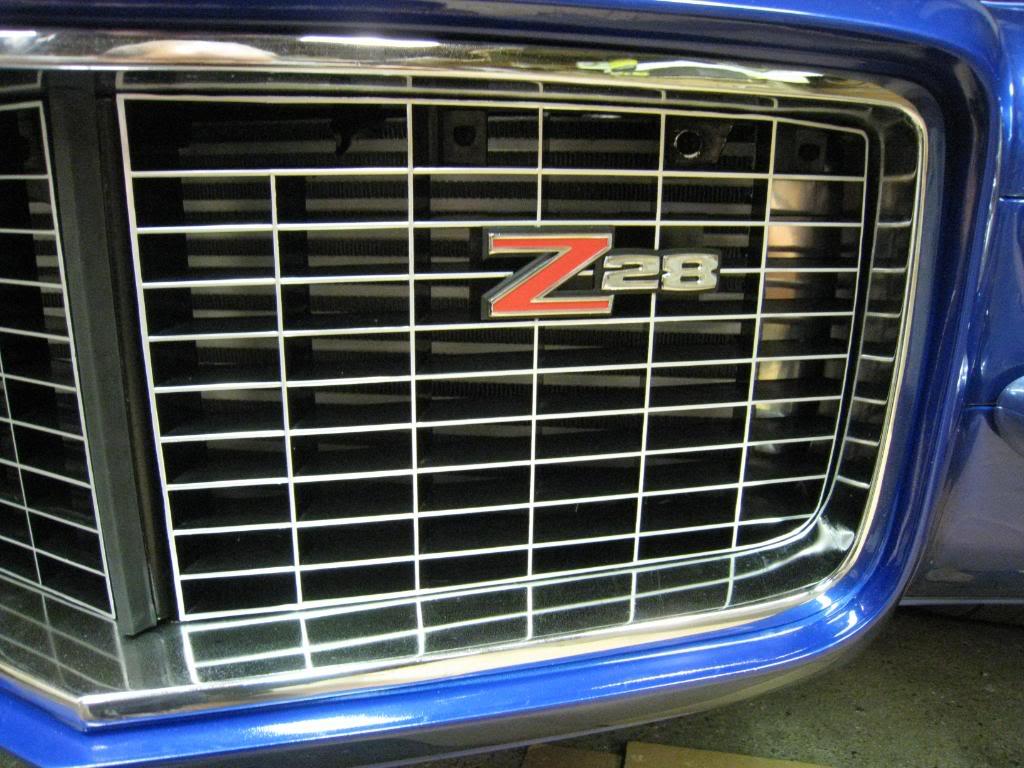
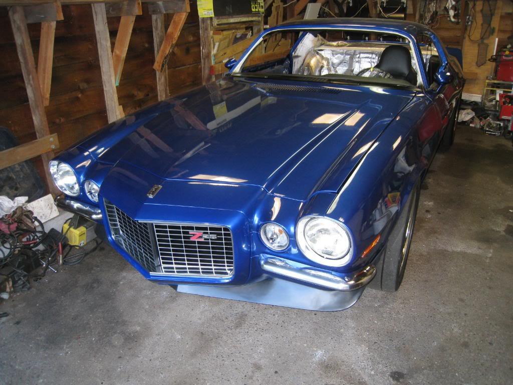
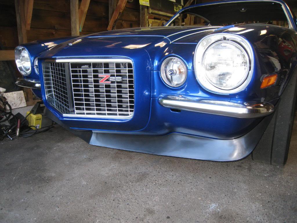
Here's a couple pic's of how it's looking now.
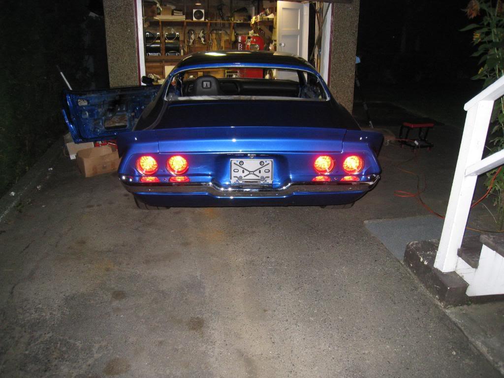
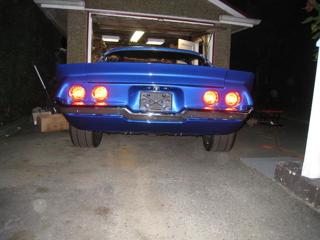
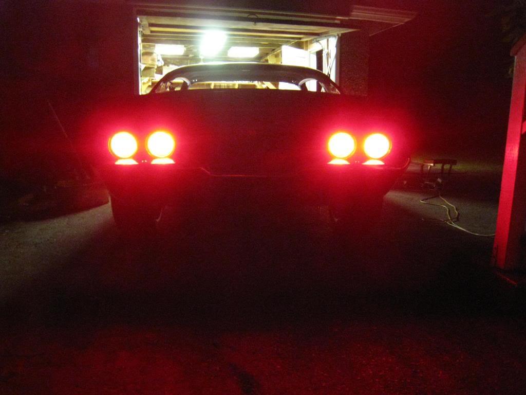
1/10/2010
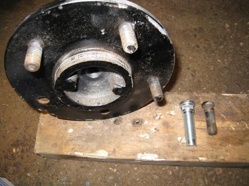
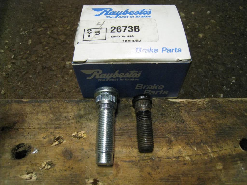
I started working on the back brakes. As usual I was met with a hurdle. I need to replace my wheel studs. I am changing them from 7/16-20x1 and a bit to 1/2-20x1 3/4.(raybestos # 2673B). So as I had to pull my axles anyway for the swap, I am going to do the seals as well. I hope this rear end holds up to the abuse I have in store for it. Worst case I swap in a 12 bolt, as these brakes bolt right onto that axle as well.
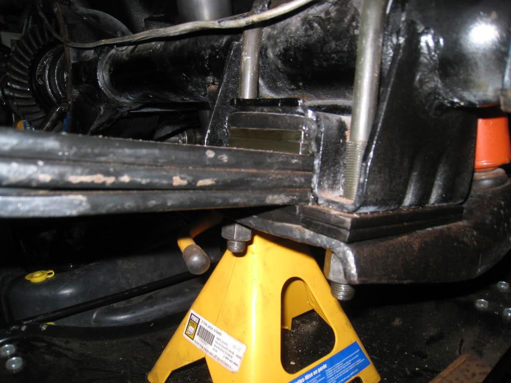
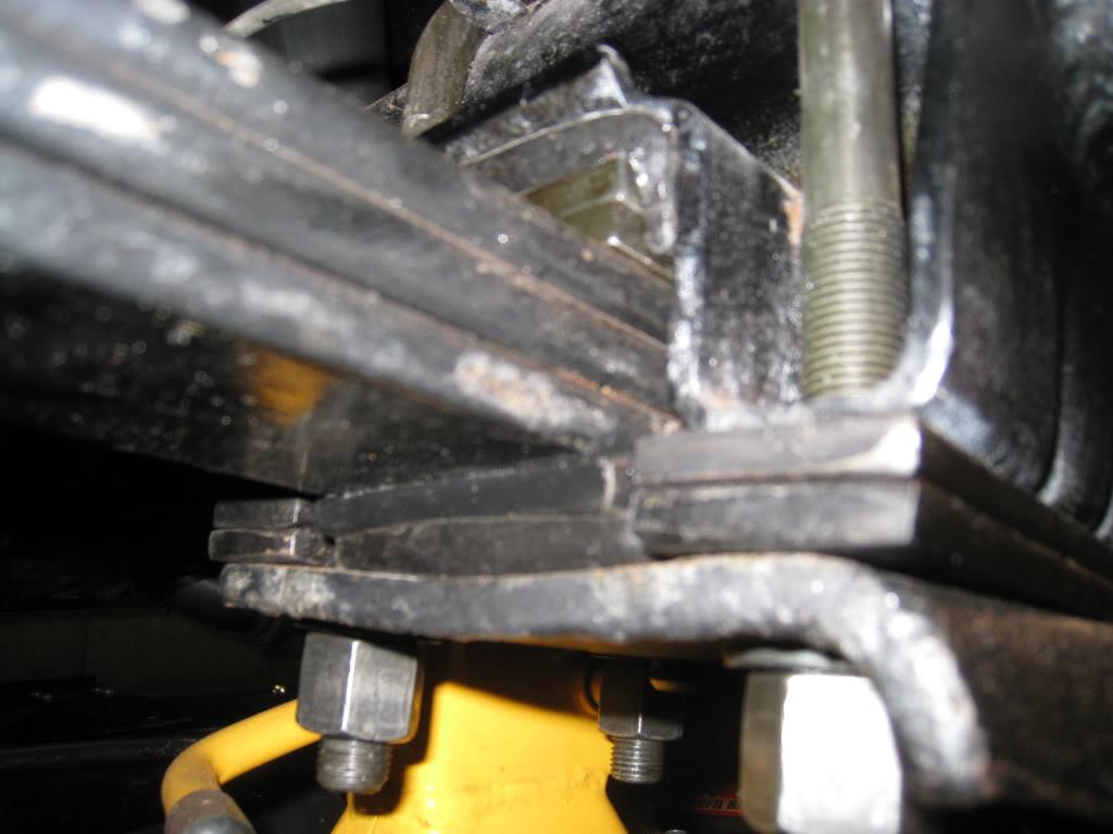
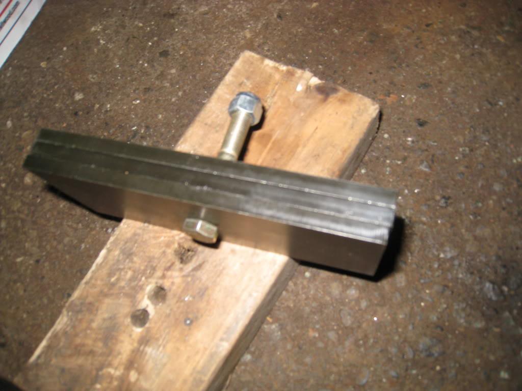
I am also lowering the rear 1/2". I got the lowering kit Hotchkis recomended but was not happy with what they supplied. It's hard to tell in the pics, but basically they send you 1/4" shims that you bolt onto the top of the leaf stack in the amount that you want to lower the car. In my case 1/2" or 2 shims. thing is, they dont supply any shims for the side of the stack. So I guess you are supposed to put the shims on top of the leaf, then tighten the U bolts to whatever tourque is recomended and hope that the lower polyeurothane isolator doesn't squish out sideways. I built my own shims, out of 1/4 flat bar, to extend the side mount of the axle tube bracket. It worked perfectly and locates the isolator. Why didn't they think of that?
old brakes
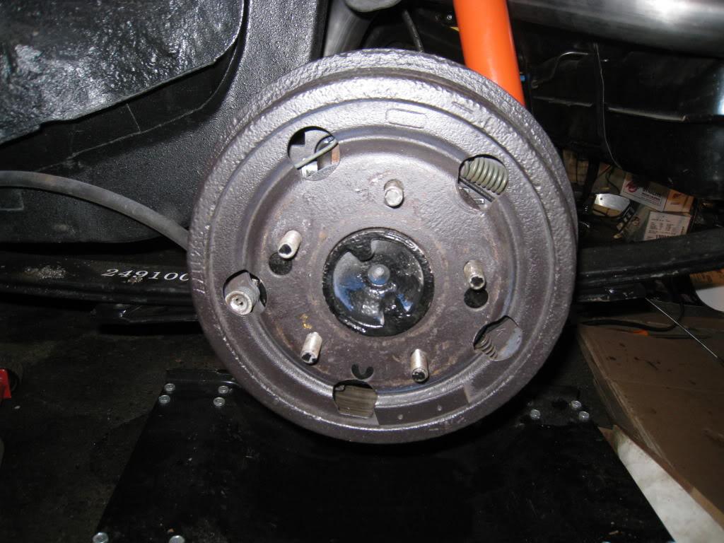
1/13/2010
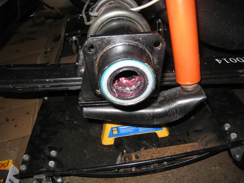
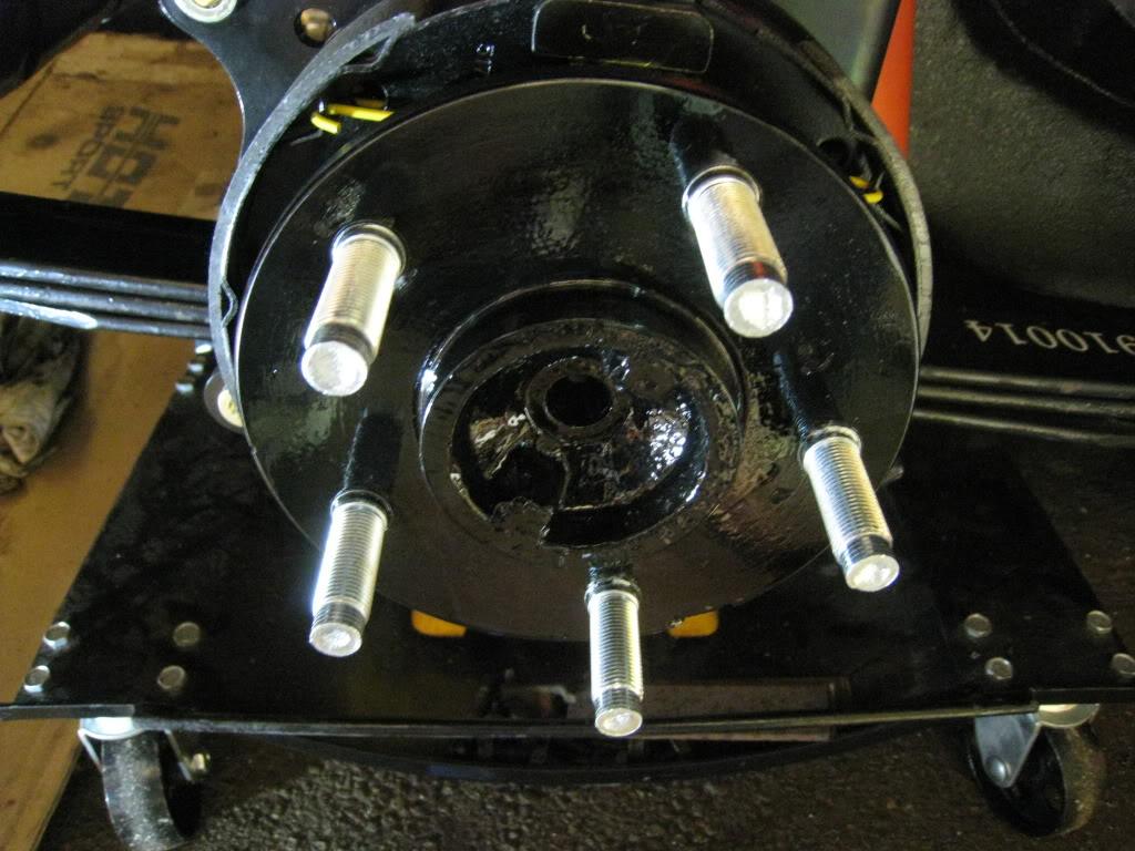
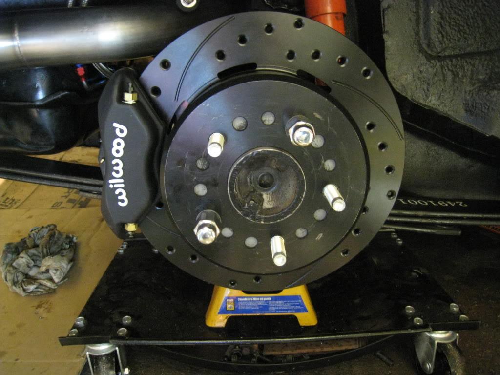
OK, more troubles... It seems even the simple jobs can take all day, or at least a good portion of them. Went to drill out the axles for the new studs and the drill bit I needed I didn't have. $28 later, for 1 bit, I get the holes done. Then the disks don't sit flush because the center of the hub has a ridge on it. Put the axle in the lathe, spun it and machined it down using a file. (didn't want to risk damaging the bearing surface of the axle with the lathe chuck, so grabbed it further down the axle and it was wobbly) OK got the disk to sit properly. Then pressed in the new studs. (Easiest part of this job) Then found the stud protrudes just slightly past the flange surface, so had to enlarge the holes in the brake disk to make em fit. Done! Yay!
Started the install.Was going well till I tried to centre the caliper over the disk. There is about .050 of axle end play... I need to figure out how to shim that down now. Can't have the disk floating left to right between the pads. It'll make for a soft pedal and unwanted drag on the brakes.
1/19/2010 I got a low mileage T56 out of an 04 gto. My 99 camaro t56 was popping out of reverse so it needed a rebuild anyway. I was doing the swap today, on my back, on jackstands in my garage by myself, holding the transmission with my hands and jacking with my leg. Sketchy... found out the bellhousing is slightly different in the starter relief area, by about 1/2". Incase anyone wanted to know, they don't interchange. I probably could have swapped the starter, but who knows. Lowered the tranny down, crawled out from under there, killed the power and inside for a drink. (some days are like this!!!)
1/21/2010
Success!! Got the MN12 transmission sorted out and installed. At the end of the day I had to swap the bell housing, hydraulic clutch bearing, shifter, and shifter ball socket thingy. (On the end of the transmission shift shaft). Used the 2 arms and 1 leg on back technique.
At the same time I installed a bulkhead insulated stud for my battery cable. It runs through the inside of the car to the trunk. I had run the cable through a grommet in the firewall but kept having visions of the whole thing going up in smoke. I've found that, with me anyway, if I think of something that could go wrong, it probably will, no matter how remote a chance. Not worth the risk.
1/24/2010
I took care of a thorn in my side today. I had put in a power steering pressure regulator thinking that I was going to have way too easy steering. I didn't. In fact it was way too heavy with the regulator at full flow. I was bummed about the whole thing, so as I do, I moved on and ignored it, being there is a lot of other stuff I can do to distract me. I removed the regulator and re did my lines. Seems way better. Although I haven't tried it with the wheels on the ground yet. I also started doing the cooling fans wiring, and the horns. Horns were easy, but the fans are giving me stress. I wanted to use the signal from the ECM to trigger them but it doesn't seem to work. More research here I guess. If anyone knows what that might be please chime in!
Pump before:


And After:

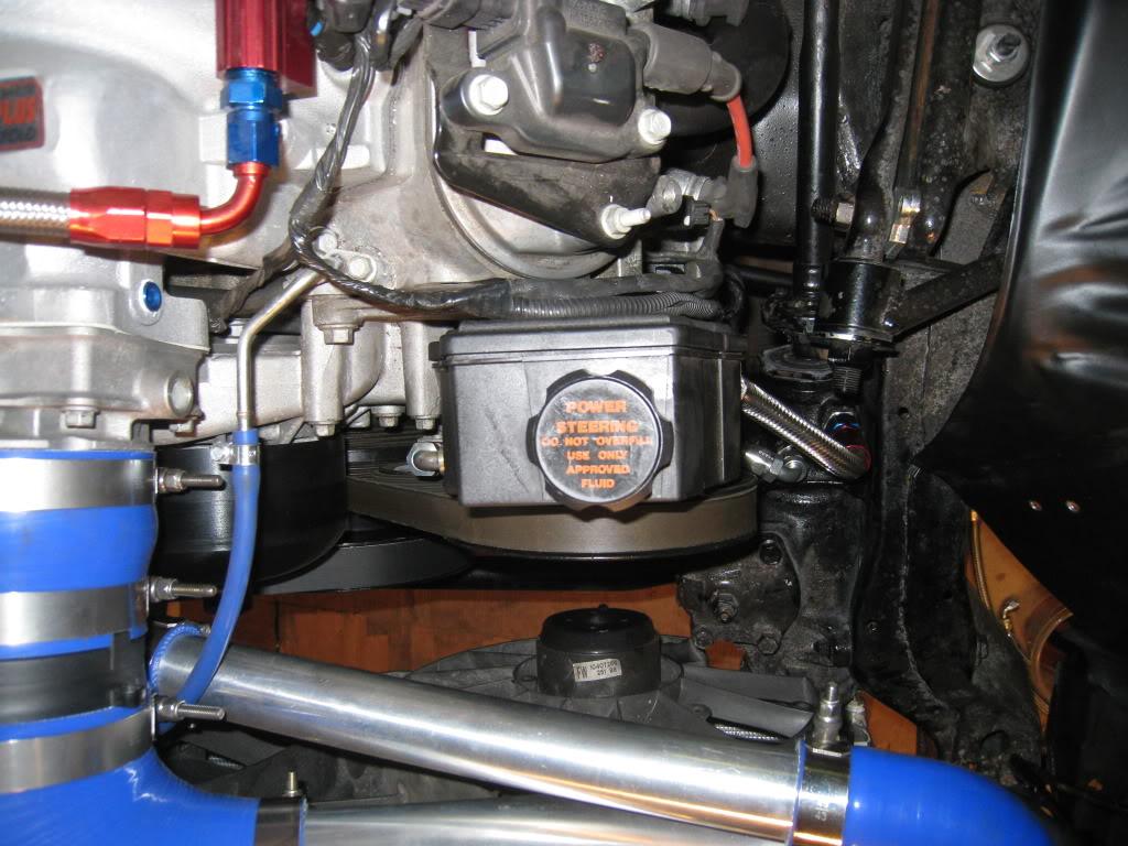
I used all aeroquip stuff for mine and made my own lines. Other than the adaptor fittings I needed, 2 @ -6 90 degree fittings around 12" of high pressure teflon -6 steel braided line, less than 12" of -8 steel braided rubber hose, 1 straight -8 hose end fitting, and 1 hose clamp.
The steering box fittings are 11/16-18 inverted flare (pressure side)-closest to motor
and 5/8-18 inverted flare (return side)
I used -6 teflon steelbraided line for the pressure side and -8 standard steel braided line for the return.
The adapter from the LSx steering pump is M16x1.5
Adapter part numbers...
Aeroquip FCM2608 (-6 x M16 x 1.5) High Pressure Adapter - this is the -O- ring type adapter for the pump
Aeroquip FCM2965 (-6 X 11/16 - 18) High Pressure Adapter <--these are inverted flare adapter fittings.
Russel 640400 (-8 x 5/8 - 18) High Pressure Adapter <-------
1/31/2010
Even MORE aeroquip fittings!!! Thought I was done with all these costly little buggers! I am running an oil breather / puke tank and had to get fittings for it. It's almost an addiction. Thing is, once you have a bunch of them, you can't just use a simple rubber hose and clamp, can you?
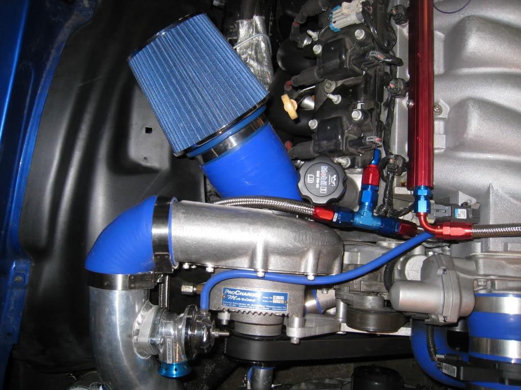
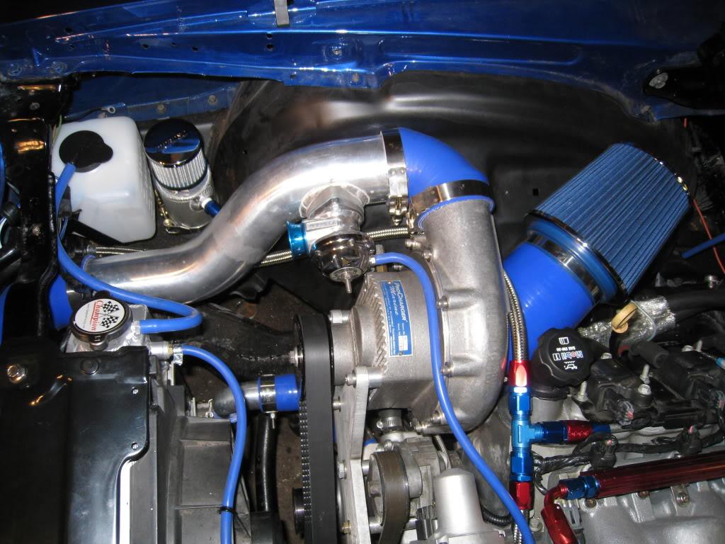
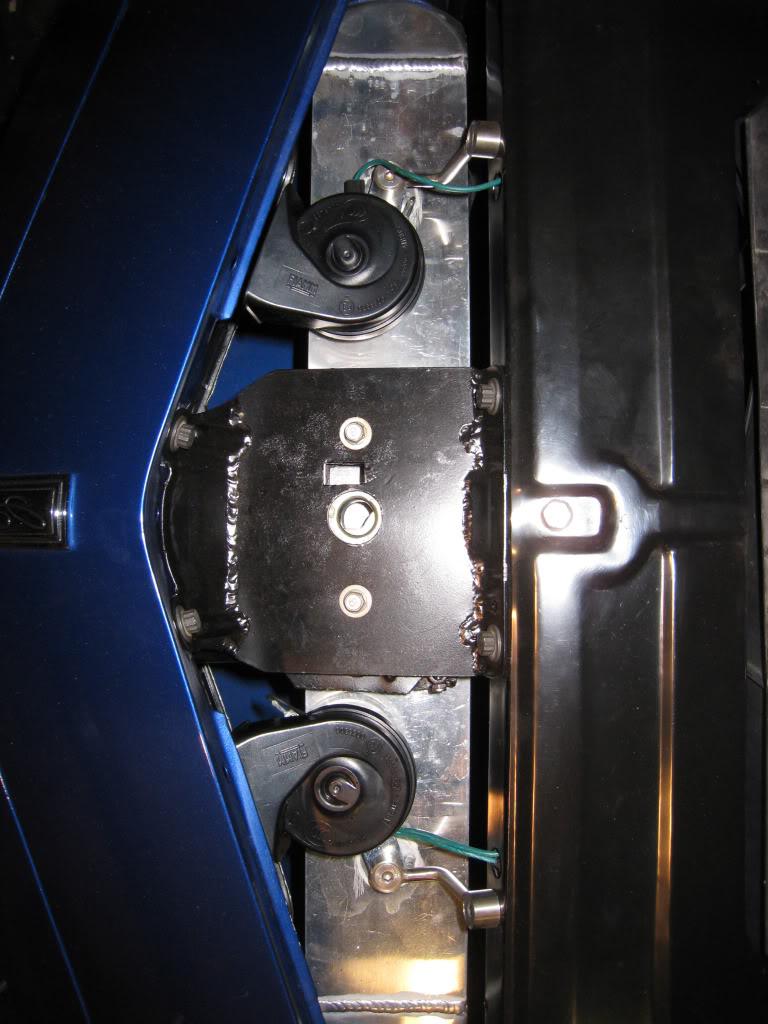
I'm starting to get down to the little things that are less rewarding to do. Got the air filter in, sort of. I want to enclose it in a heat resistant box, that gathers air from under the fender, but I also want to drive the car this summer... I'm telling myself that it's good to leave some things to do later. Also got the horns in, but don't like the wiring much, or the brackets, so they may come out again. Sound good though. Put in a coolant resevoir tank as well. It's actually a windshield washer tank for a 67-72 chevy pickup. I hope it doesn't melt.
2/2/2010
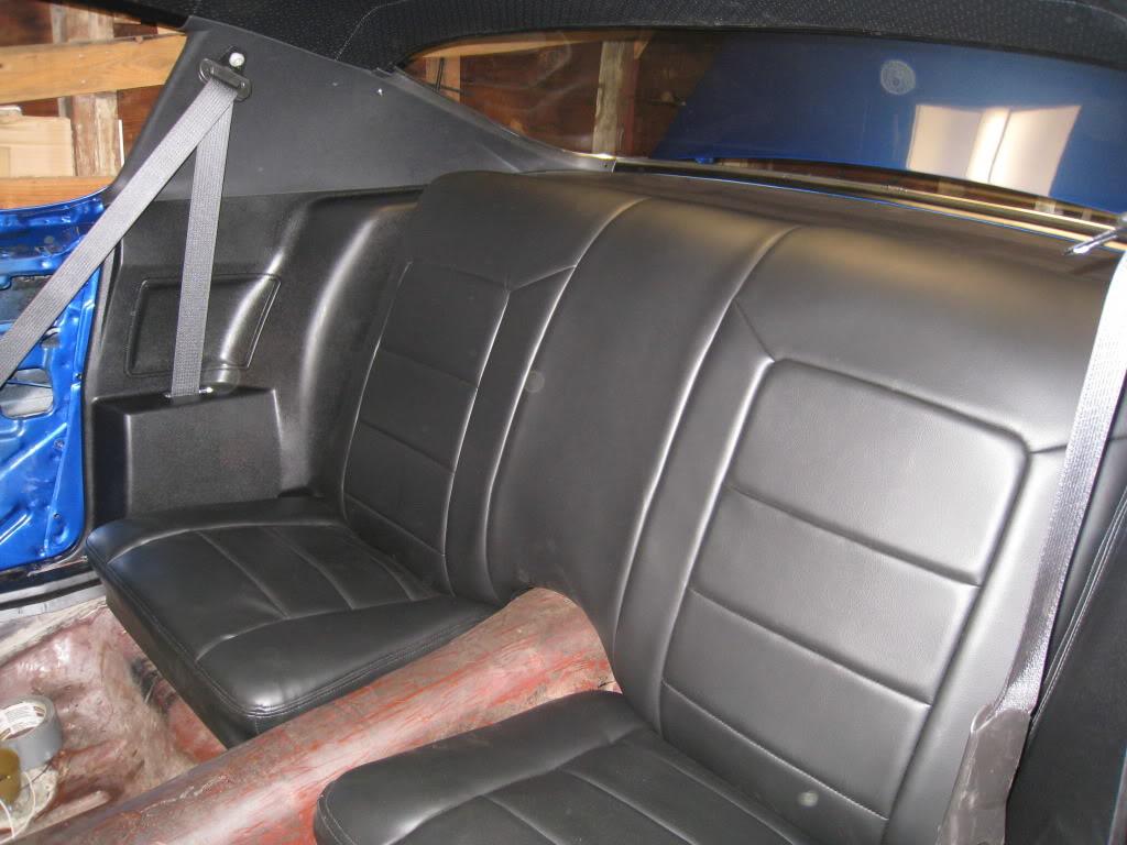
I've decided to put in a roll bar and frame connectors to stiffen this thing up. I started putting the rear seats in and the modified side panels (modern seatbelts) so that I can see where to put the bars. I'm excited and nervous at the same time about the roll bar. Goint to try to make it non-intrusive.
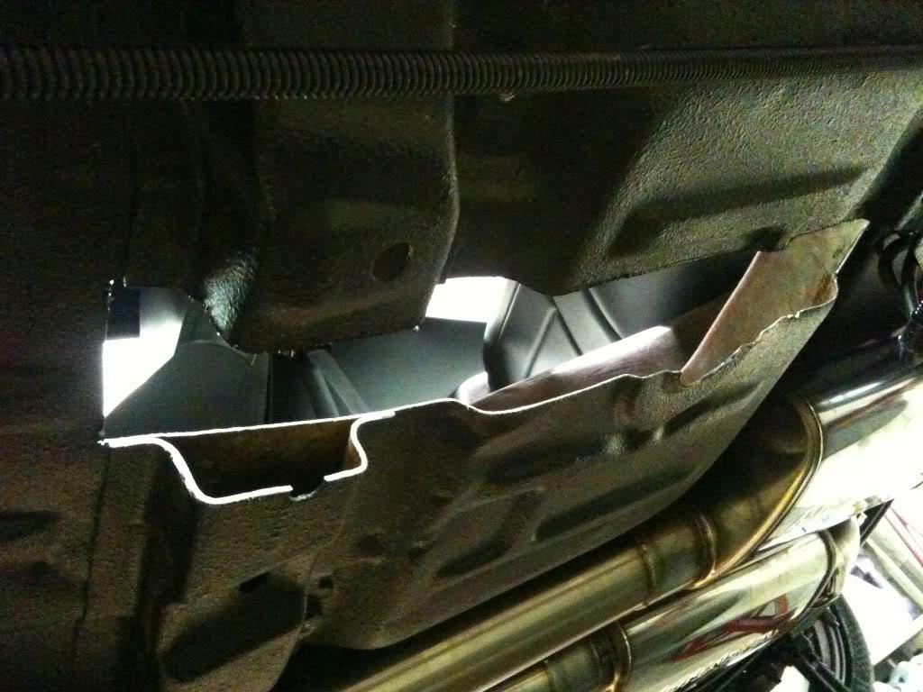
2/5/2010
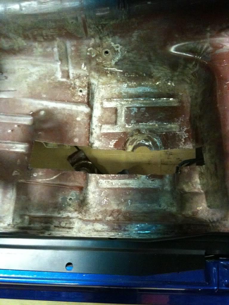
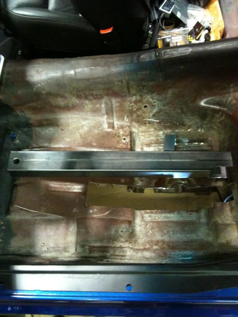
There's no turning back now! I cut a big hole in my floor. I started by using a piece of string to figure out where to cut. I held the string tight from inside the edge of the front subframe and stretched it as I lined up where a straight line from the front subframe would go... Wow, that sounds confusing. Basically I wanted to see where to cut if just say the front subframe was extended straight back. When I found that I marked it. After laying out the straight line, I measured over 3 inches and marked again. After all the layout was done I drilled small holes through the corners and connected the dots. I drilled a few small holes close together so that I could get my saw blade through, then cut away.
I then measured the length of tubing I would need and cut that. At the front the tubing goes inside of the original subframe. I cut a 2 inch "window" out of the end of it, and drilled a hole in it for the original front subframe mount bolt. In the back I trimmed the tubing to fit. There was a bit of fine tuning, (trimming) and then I bolted it in. I started welding it in. Monday I will continue welding, and boxing in the rear subframe.
Forgot the camera, again, so had to use my cellphone. -sorry-
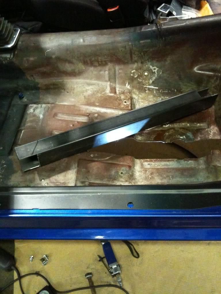
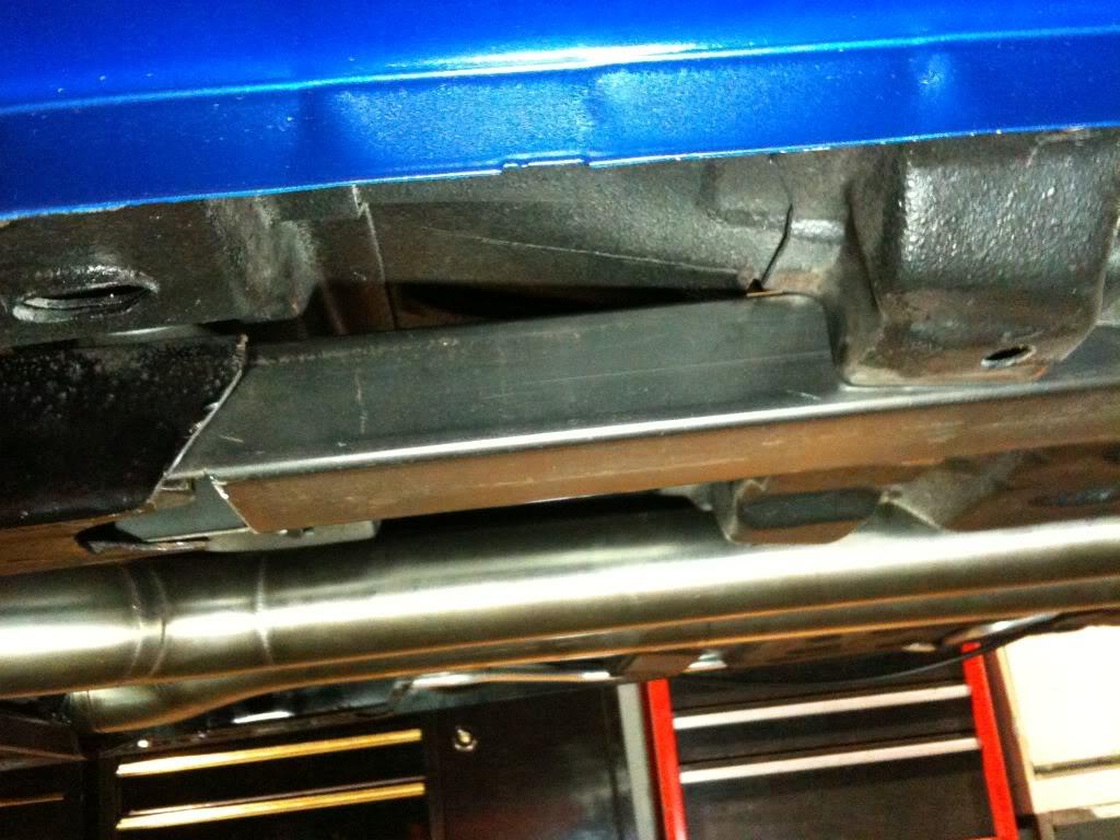
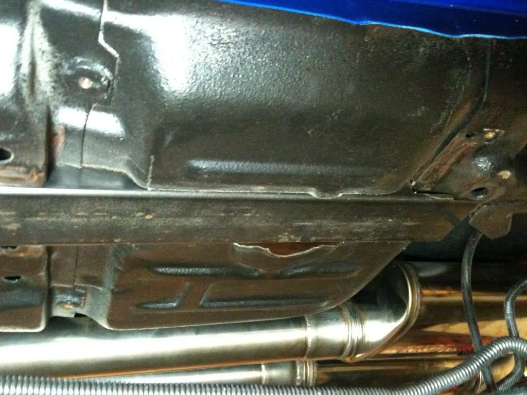
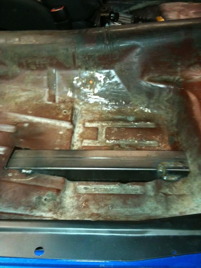
2/8/2010
Been a long day, on my back, under the car! Started my day with a trip to the metal supply shop to get the tubing for my roll bar... That'll be another post !
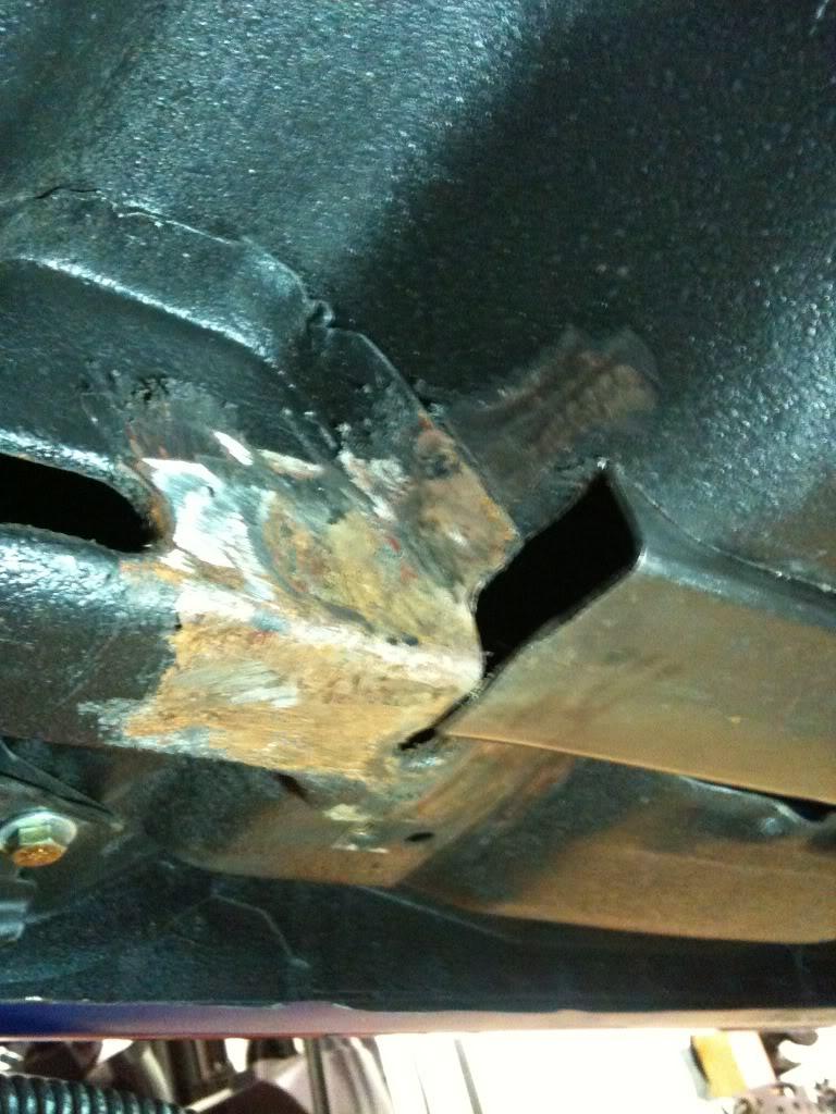
I finished the drivers side connector today. Happy with the result, and thought of a few more tips to put in here. Make sure your front subframe is nice and square, because after you weld these in, you're done. There's no adjustment after that. Another thing I should mention is that the weight of the car should be on the suspension. Believe it or not, the body/chassis will sag differently if say you have the car on jackstands on say the frame. I initially put stands under the axle and under the front subframe, but before I welded everything solid, I put the car down onto it's wheels on a set of old t. That way everything is sure to be sitting where it wants to be. Of course the ground should be level as well, and all the 'blocks' the same height. (I used a set of old 9 1/2" wide wheels)
Boxing in the rear subframe was fairly straight forward. First I removed the bracket for the park brake cable. (I have aftermarket rear brakes which use fully sheathed cables. This step could be skipped with stock cables, you'd just have to make the filler box accordingly)
I made a corner piece out of tubing, trimmed it to fit perfectly, (this takes time of course, many trips from under the car to the bench and back) and then cut it in half. I had to cut it in half length ways so that I could weld it in fully. After it was in 2 pieces I used a welders magnet to hold it back into it's original shape, held it in place, then tacked in only the upper piece. I pulled out the lower piece and fully welded in the upper piece. After that was done I used the magnet again, held in the lower piece, and welded that in.
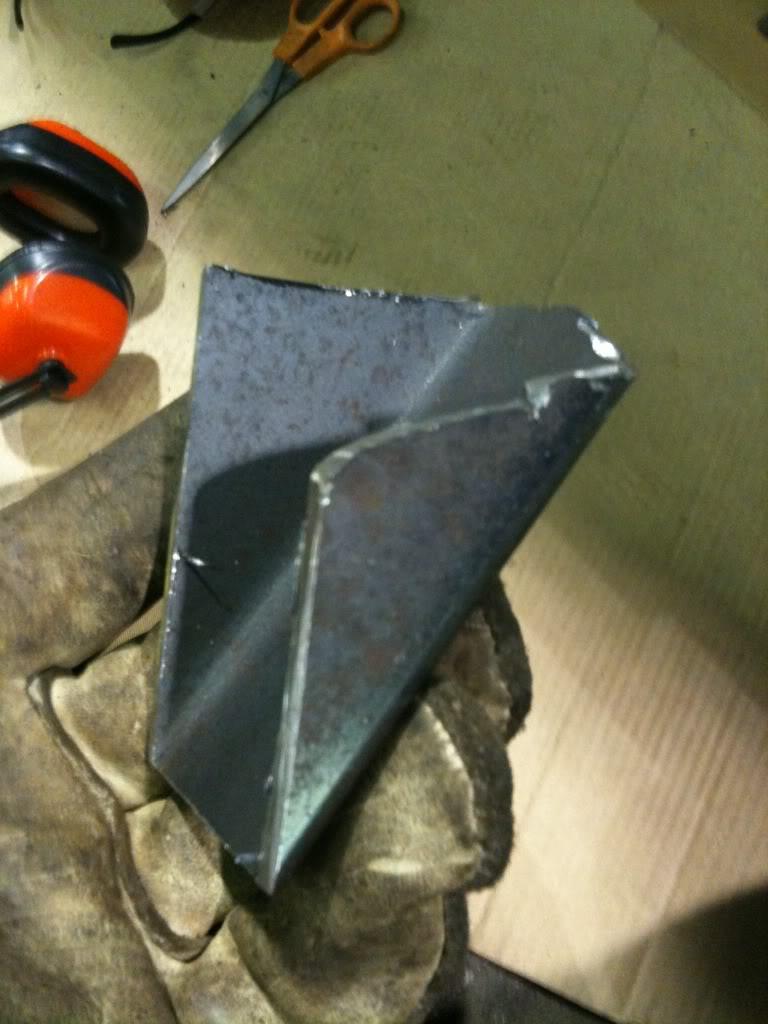
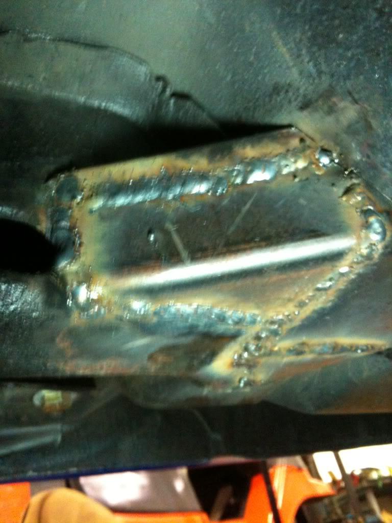
I made another corner piece for the other side and welded that in as well.
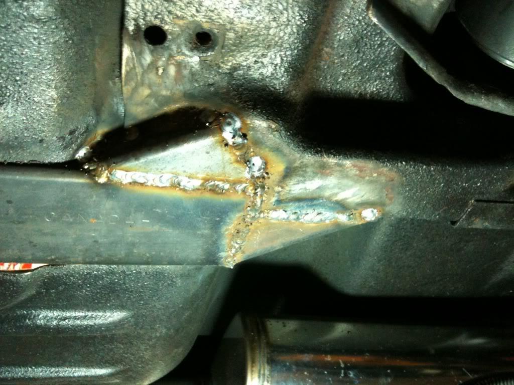
From the inside I stitched in the floor to the tubing.
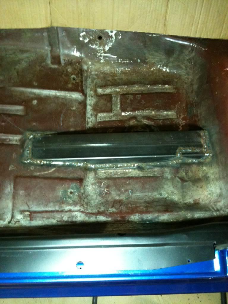
The last thing I did was finish weld the front subframe tube to the 2x3 connector. (Again being sure everything was straight.) - I should note here that there are alignment holes on the front subframe that line up with the body. The drivers side is where the body mounts near where your feet would be. This line up hole is a round hole in the subframe and a round hole in the body. On the passenger side there is a round hole in the subframe, and a slotted hole in the body (slotted left to right). I was extra careful to make sure these were aligned.
A quick coat of paint and it's time to do the other side.
2/11/2010
Picked up my new Eaton True Trac and Moser Axles yesterday, along with bearings and seals etc... Man do I hate crossing the border...It used to be no prblem, but I tell ya, it seems like everyone is paranoid now. When I came back across the Canadian border guy asked me if I had opened the boxes that my stuff came in. I said no, just looked at the packing slips. He went on and on about "well, what if someone put a bag of coke in there? Don't you think that transporting a package across an international border without checking its' contents is maybe a problem?!?" wow. I said I guess I'm just naive to American shipping habbits... He made me open my boxes. Nope, no coke...
I welded in my roll bar mounting plates today. Time to start bending tomorrow!
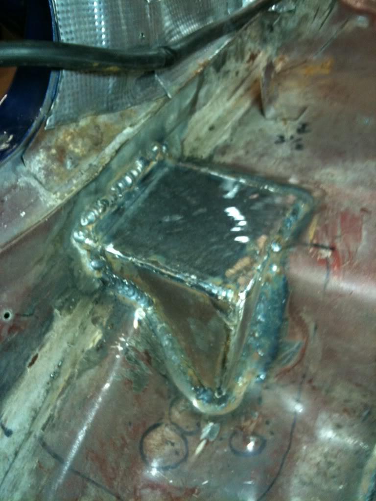
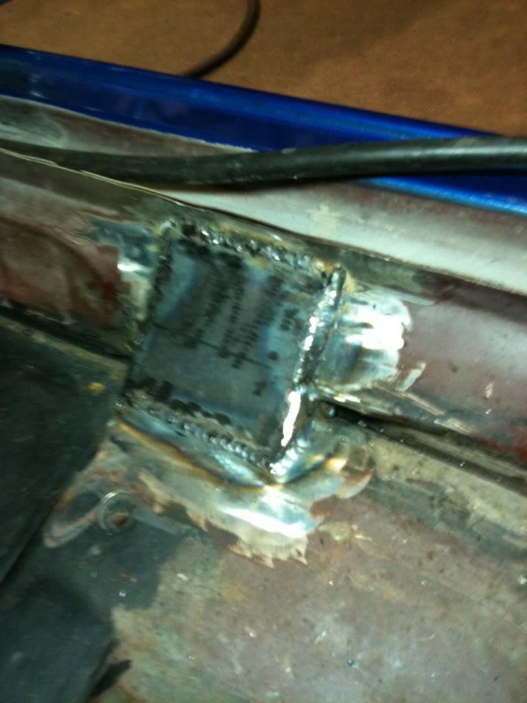
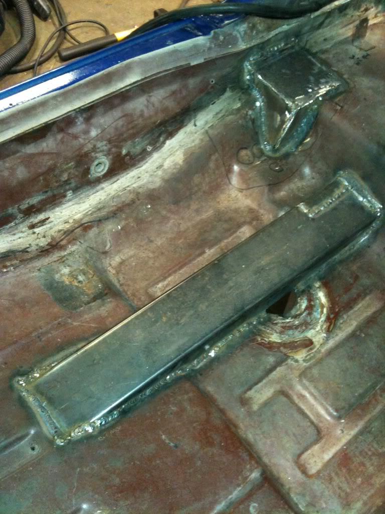
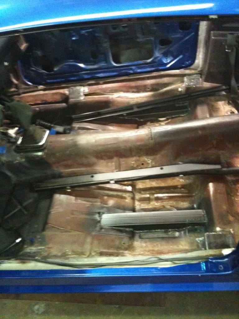
2/12/2010
Measured up the car for the main hoop today. Measured about 150 times. tried several different methods to get angles and measurements and by the end of it instead of using a bending program, I used a home made radius wheel and a tape measure. Got the main hoop bent and tacked in. the upper bends are 60 degrees, the lower ones are 35 degrees. I think I could have gone slightly less on the bottom bends, maybe 1 or 2 degrees, but the bend does follow the interior very nicely.
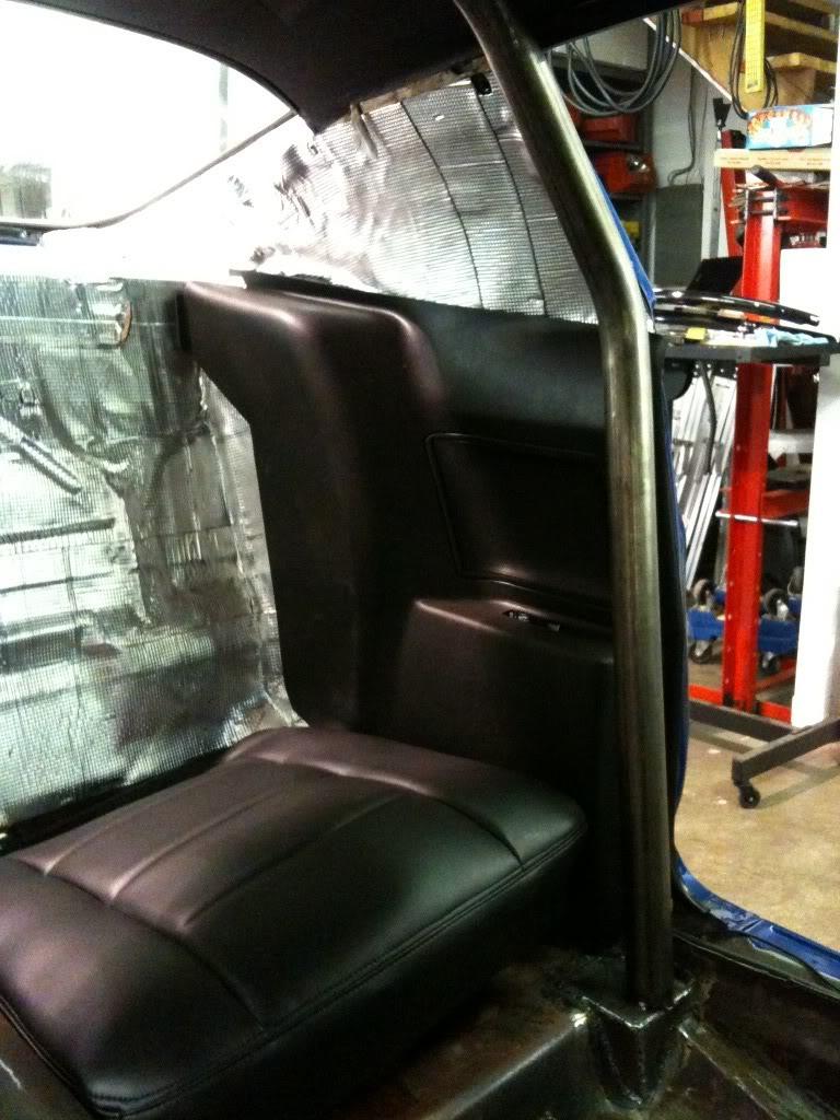
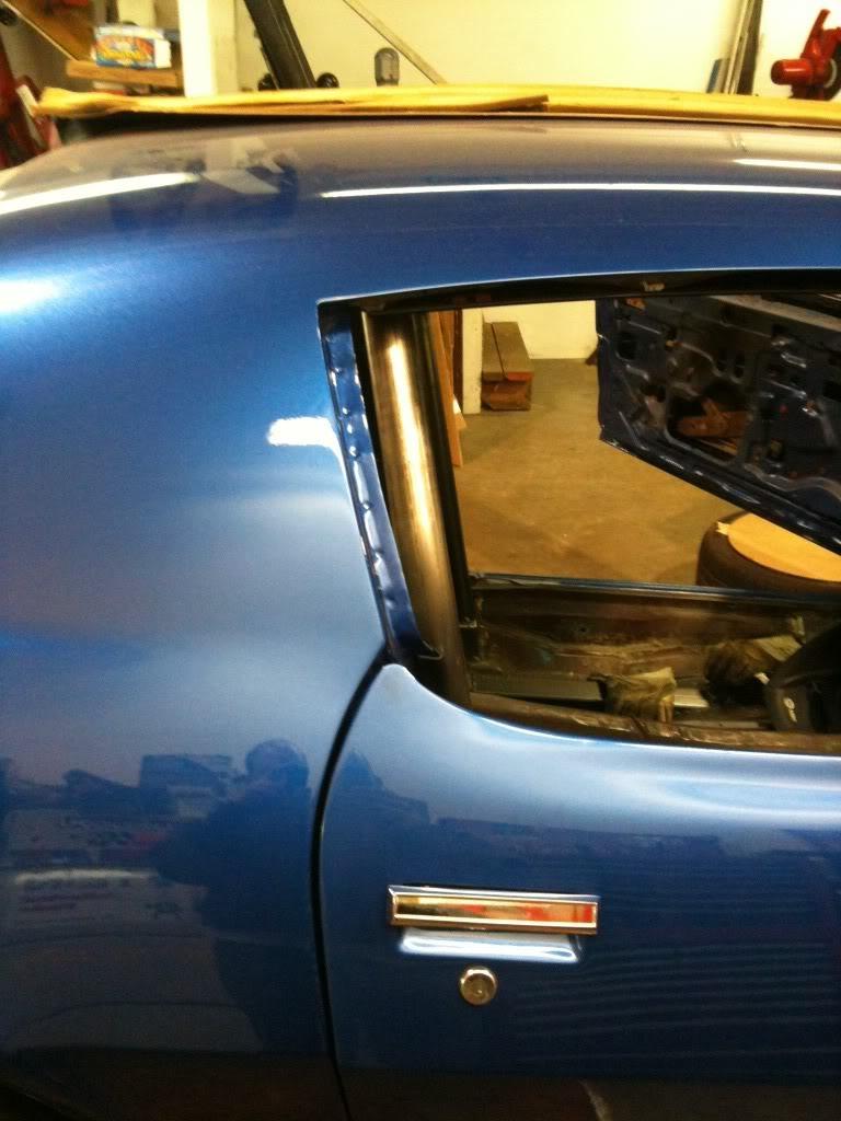
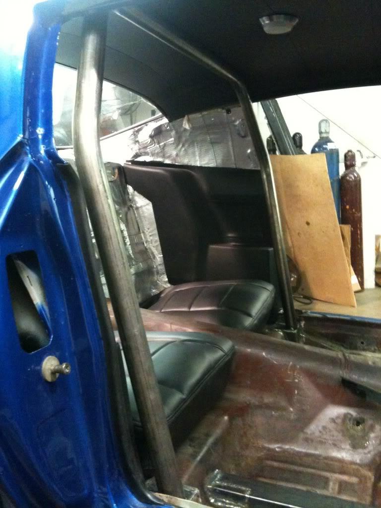
2/15/2010
Time consuming day today. Cut the holes for the rear down tubes. Made the tubes, and plates. Mocked them up.
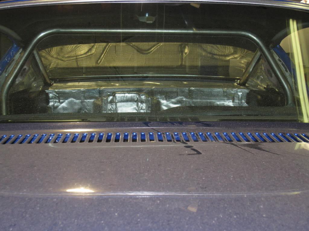
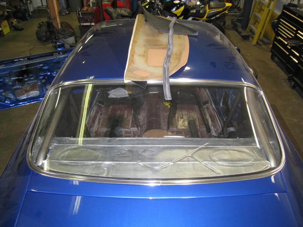

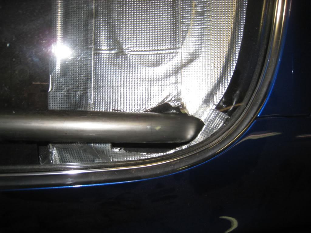
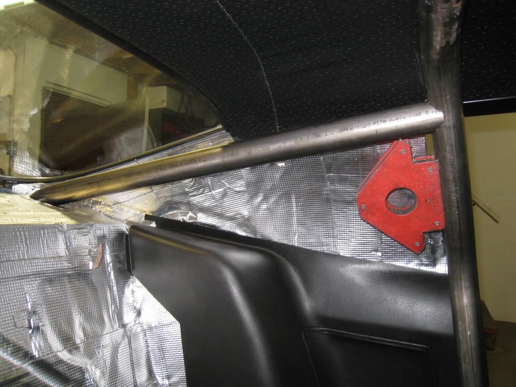
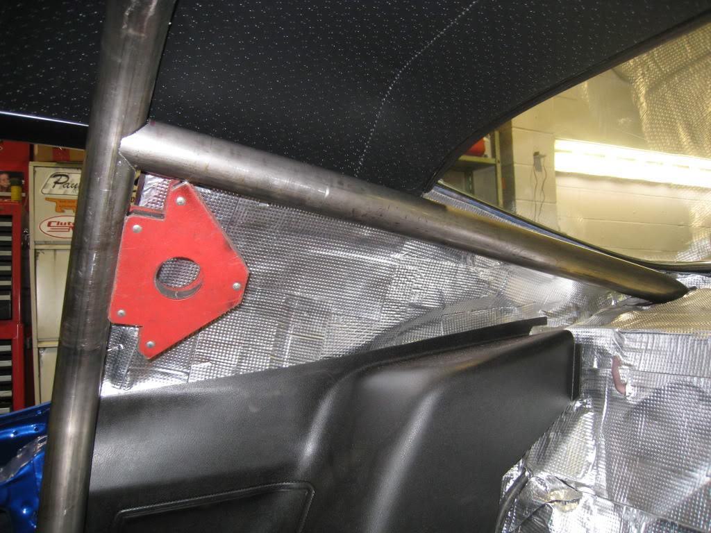
2/16/2010
I got my rear tubes all done today. I painted them where no welding would be before I installed them as I know it's going to be really tough to paint them later. I tacked them in, and as I had mentioned before, I pulled the whole thing forward to finish welding the down tubes to the hoop. I TIG welded them and even with the bar forward it was very difficult. It didn't help that my headliner is in and I had cardboard in between it and the bar. I then painted the welds, then put the hoop back in place and started welding it in. Got sick of welding so moved on to making a crossbar for the hoop. I sat my seats in to be sure that I could recline without hitting it, and that if someone did sit back there the could actually do so although their legs would be around the bar on the right side.
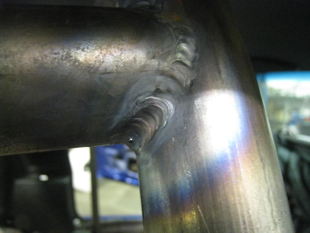
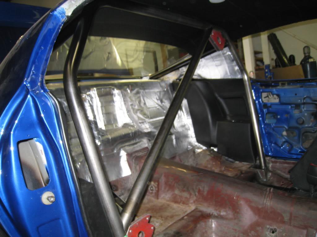
2/27/2010
Bit more work done... It's sick how long this is taking!
Belt bar for behind the drivers seat. I machined collars out of 7/8 solid stock and welded them into the bar.
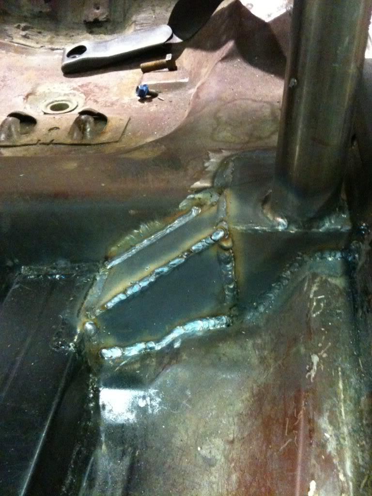
Tied in the main rollbar hoop to the frame connectors.
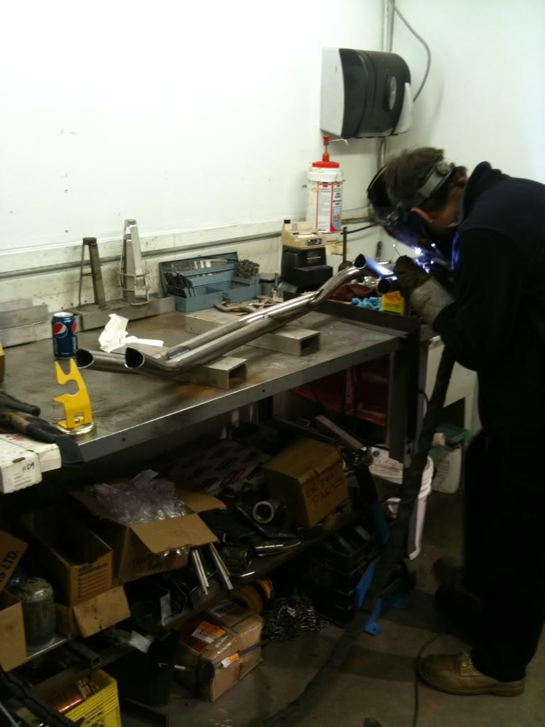
A sneak peak of my door bars. Thanks goes to Mikey for finish welding these for me!
3/4/2010
Finished the roll bar. Before you guys get all crazy, I know that the door bars aren't legal height. The main purpose of the bars in my car is for chassis rigidity. The main hoop is good for safety of course, and I did bring up all my mounting plates to the legal 6x6 size (or at least the 36 sq. inches anyway) But again, I didn't mean to have it pass tech anywhere. I will use the car for the occasional road course track day, maybe an auto cross or two, and definitely some on road corner shredding. (I hope).
Here's my way too labour intensive door bars. I built them like this to tie in the front subframe mounting points to the roll bar which is also tied into the rear subframe and the subframe connectors. I wanted my entry and exit from the car to remain unobstructed.

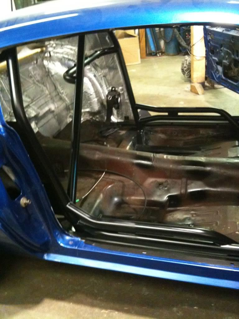
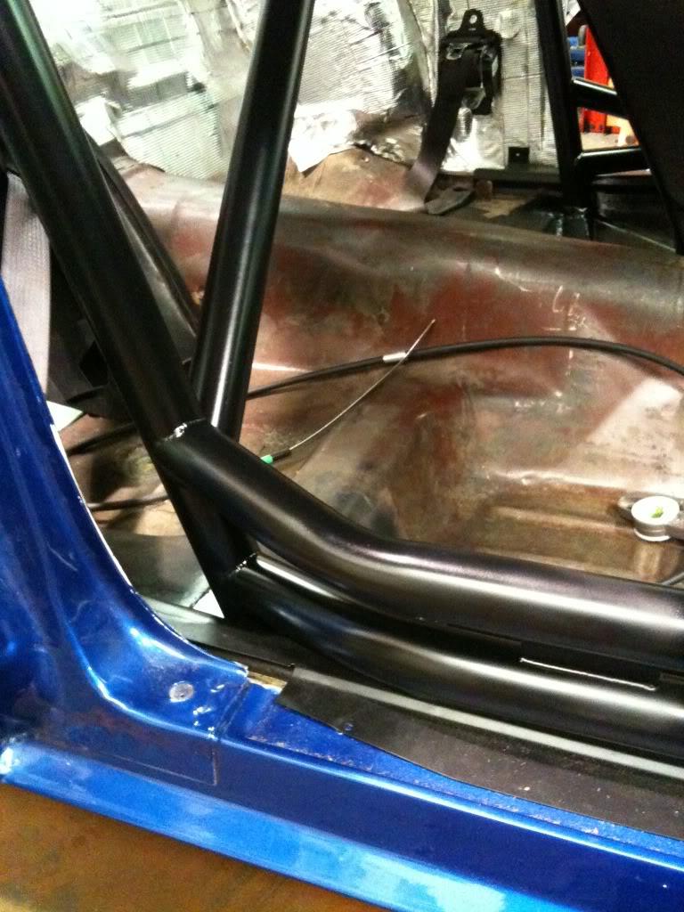
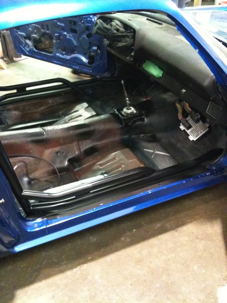

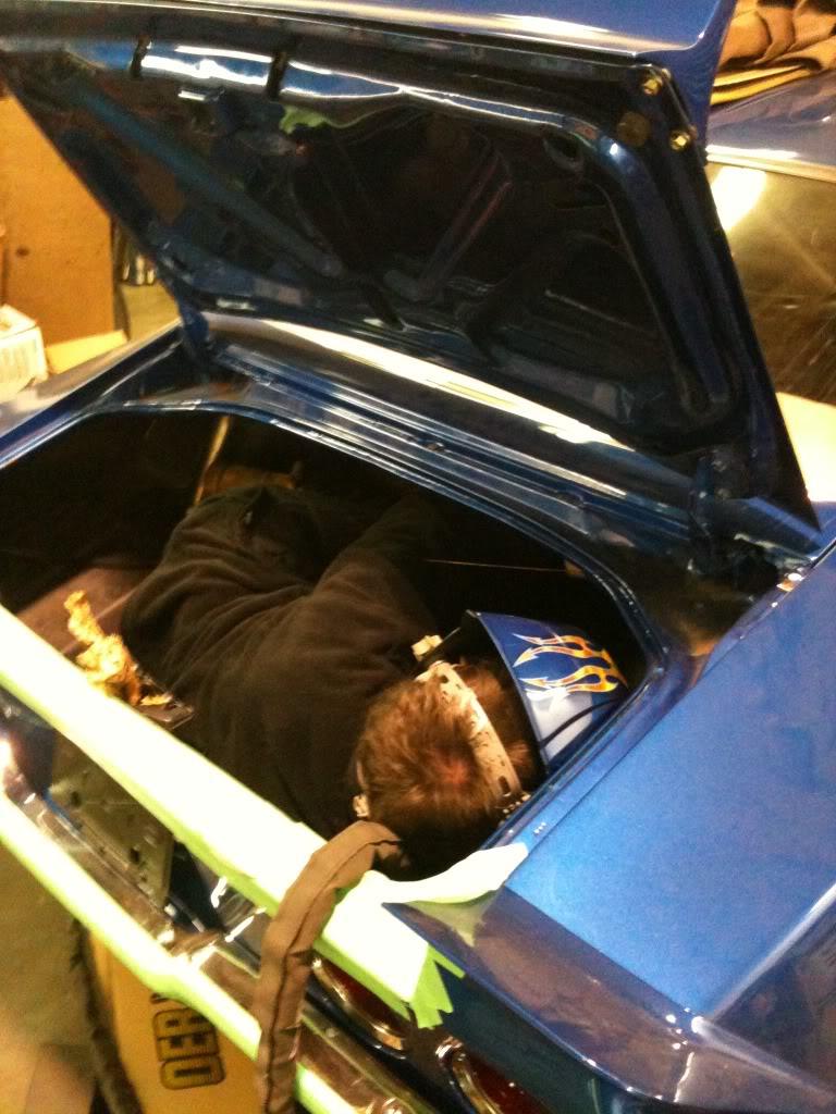
Here's my good friend Mikey tig welding where I lack the skills and apparent flexibility. He must be a good friend...considering he's in my trunk. And, yes, he's a full size human being. 6' even! If anyone needs any kind of fabrication or welding done, even maintenance, the guys here at Custom Metalcraft can do it all. http://www.custommetalcraft.ca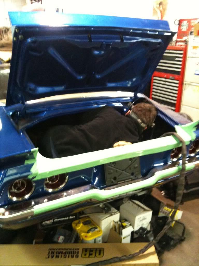
3/15/2010
Been a bit since the last post. I finished up the roll bar, and installed the rear seats, surrounding panels, and carpet. Also installed the front seats. Put a day permit on it and DROVE it home!!! I even put it through our local emissions test (aircare) on the way home. ( Cheated a little by removing the supercharger drive belt and ran it on factory tuning ) Passed with flying colours. I was so excited I insured it fully the following Saturday and put 40 miles on it. Total mileage so far, 47! The power steering pump is leaking. That sucks, but it was off of a high mileage 99 F-body so I ordered a new one. Still have lots of stuff to do, but at least I can drive it to the parts store now.
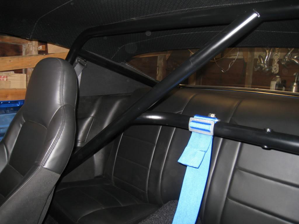
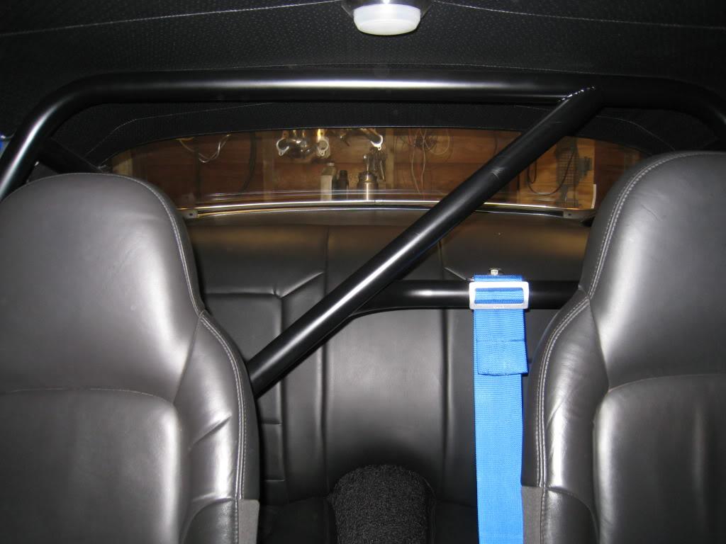

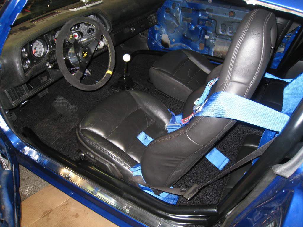

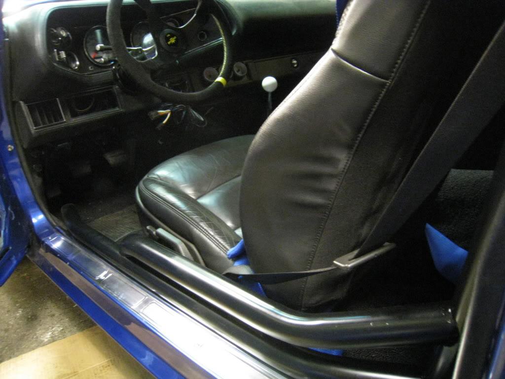
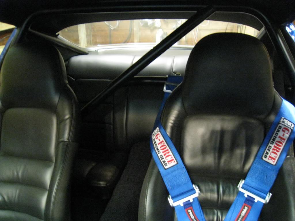
The seats are from a 2007 Corvette, actually, the same car that the engine came from. I modified the corvette seat tracks. I drilled out the rivets that held on the mounting plates both front and rear of the tracks. I figured out what the stock spacing (for the Camaro) was, then welded the front mounts back on at the correct width. The rear mounts were more complicated. The corvette tracks are very long, so I had to cut down the length. In doing this, you remove the slider stops from going backwards, also if you go too far back the roller ***** will fall out from between the tracks. Not really an issue in my case as there is no need to really move the seats that much. The drivers seat is power. Which is cool, and it works well and is very comfy. The seats do tip forward as well, and you could get into the back that way and they latch forward which makes working back there a bit easier. I used the Corvette seat belts as well. That info is in here somewhere a ways back.
4/23/2010
Well guys, it's almost done, well, not really, but it is done enough to be in the B.C. Classic & Custom Car Show at the Tradex Building at Abbotsford Airport this weekend, April 23,24,25. So come out and check it out, you'll find it at the KMS CAR PARTS booth. Don't forget to vote for me for best Pro Touring!!! <--- (shameless attempt for votes)
Here's a link for the show...
http://www.bccustomcarshow.com/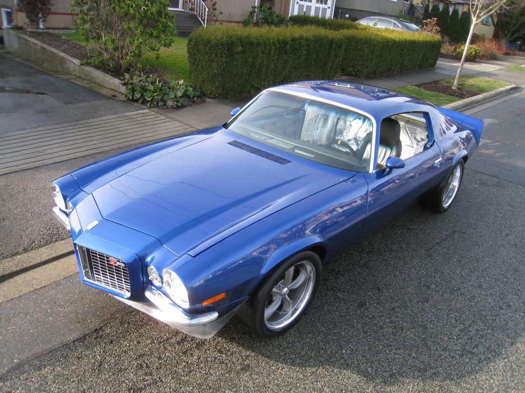
5/13/2010
Been a while since my last post. Alot has been done. I've put about 600 miles on the car and have had a few bugs to work out. The interior is all done. I've had one fuel pump go bad, so since I don't like just doing straight repairs, I dropped the tank, cut it open, and welded in some baffles and made proper mounts for the pumps. I also had a weird braking issue. After a right hand turn, I would lose a bit of brake pedal. It was like the next brake application had more freepedal than before. Only after a right turn though. I thought it through like a detective and figured it out. The rear axle end play is set by a bushing that is held between the axles in my true trak posi. I found that the spacer allowed 25 thou' of end play. Enough for the axles to shift thereby pushing the pads back in my calipers and giving that extra travel on my brake pedal. Took it apart, measured the end play with a feeler gauge, then just made a new spacer on the lathe out of stainless. Problem solved.
The big news!!!
Removed my FMU (rising rate fuel pressure regulator) installed 52# injectors, and DYNO tuned.
On a conservative Mustang Dyno, the car put out 462rwhp, and 459ft-lbs torque.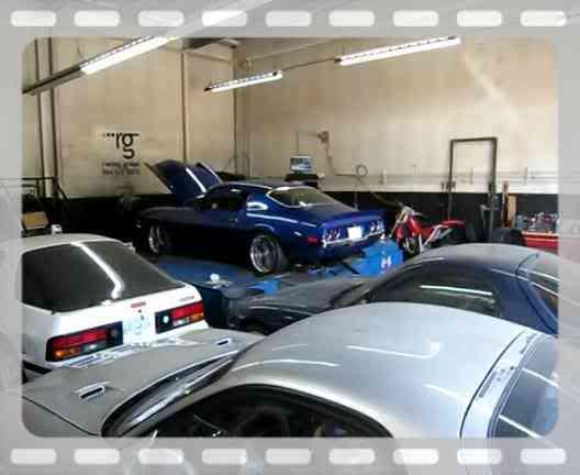
5/19/2010
Took it to the track this weekend...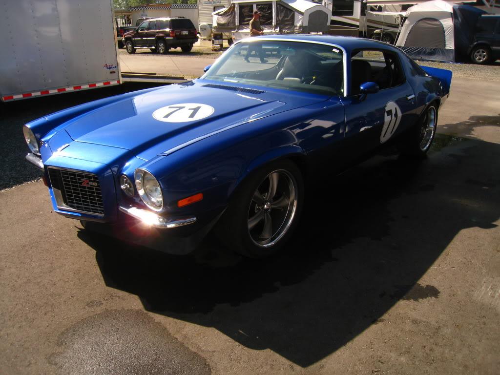
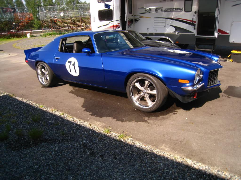
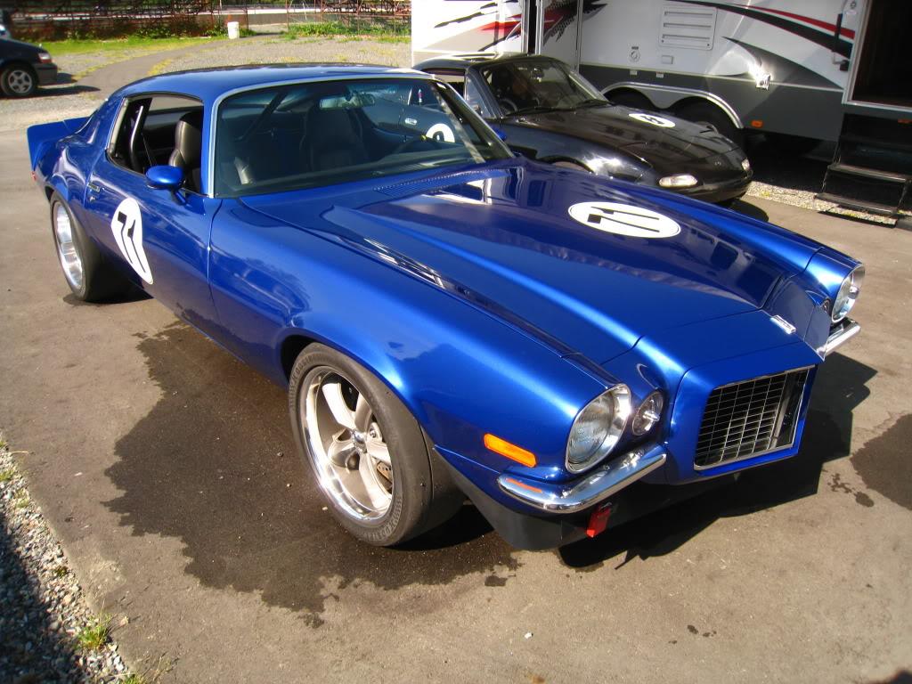
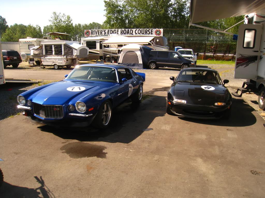
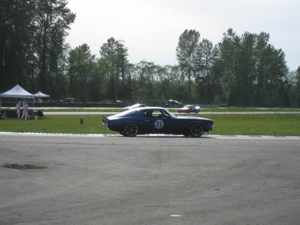
6/1/2010
Well the procharger is coming off, and the Twin Turbo's are going on. I'm going to sell my Procharger setup, headers, maybe even the injectors and tune. If anyone is interested, PM me, details of the parts are all in this thread. -make an offer-.
7/7/2010
Enough said?!?!?!?
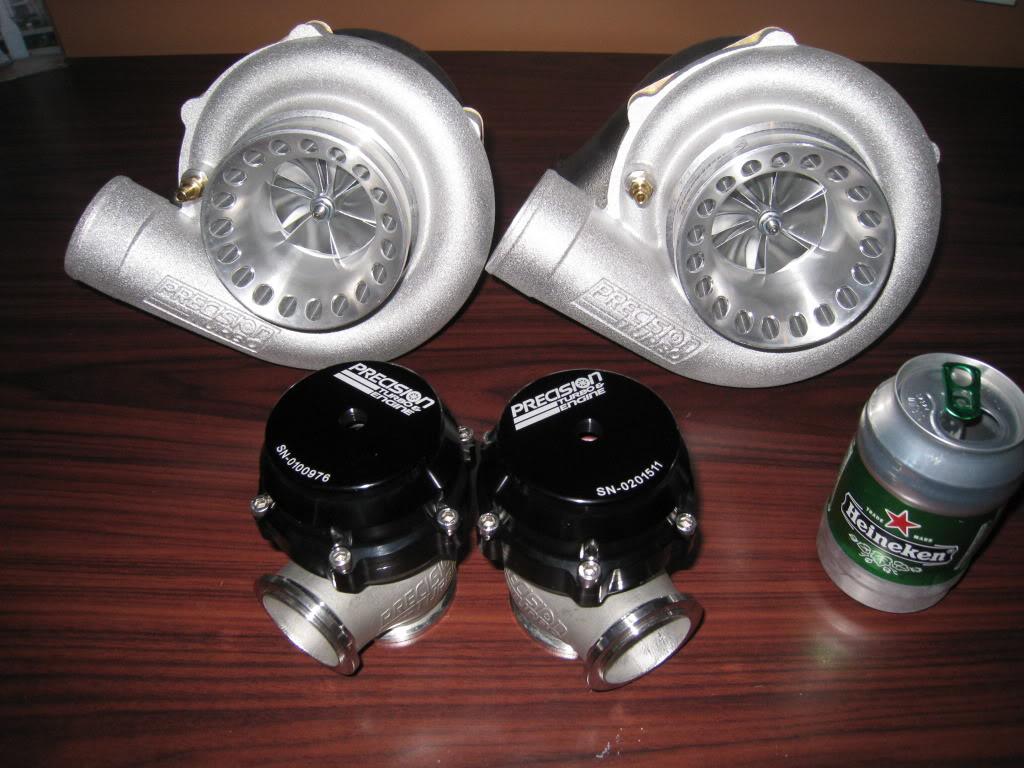
7/24/2010
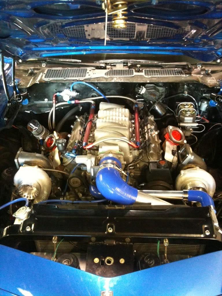
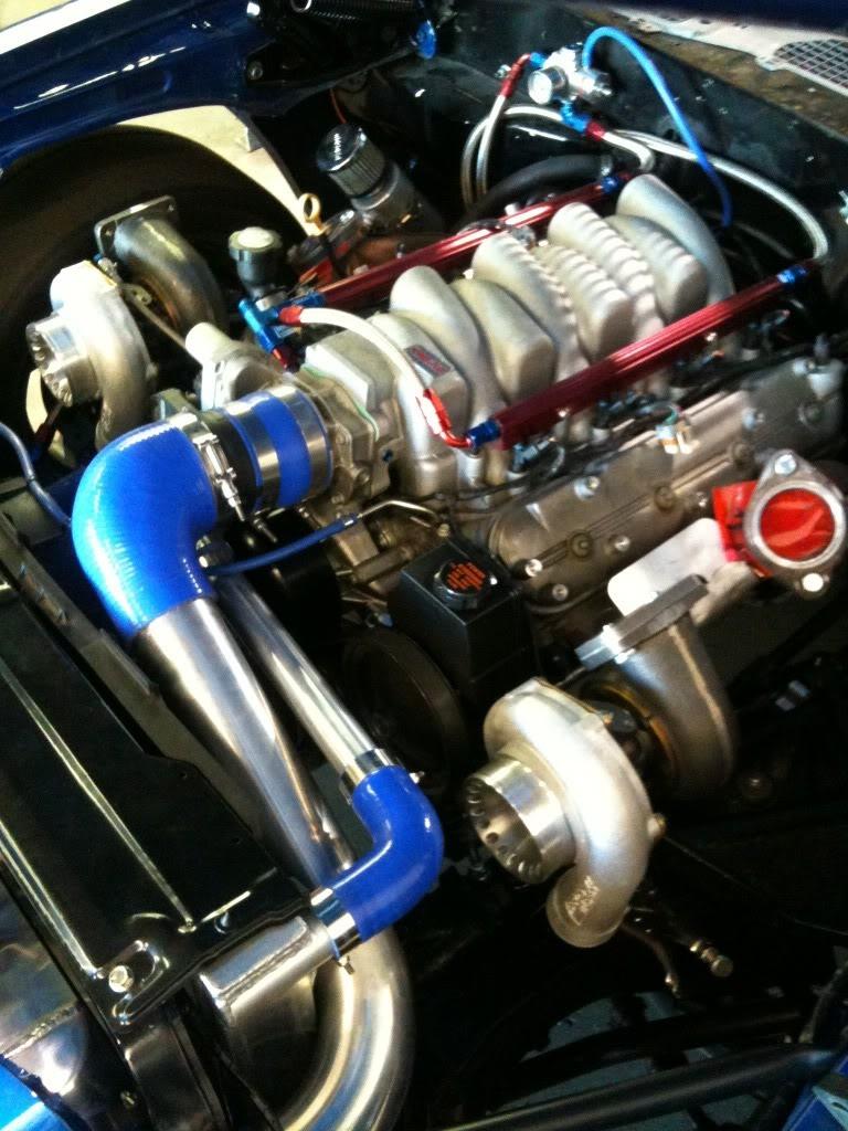
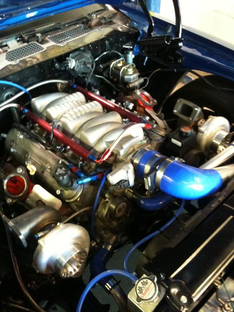
Started the next stage of my build this week. Gotta say sorry to frojoe for taking back the manifolds I gave him.
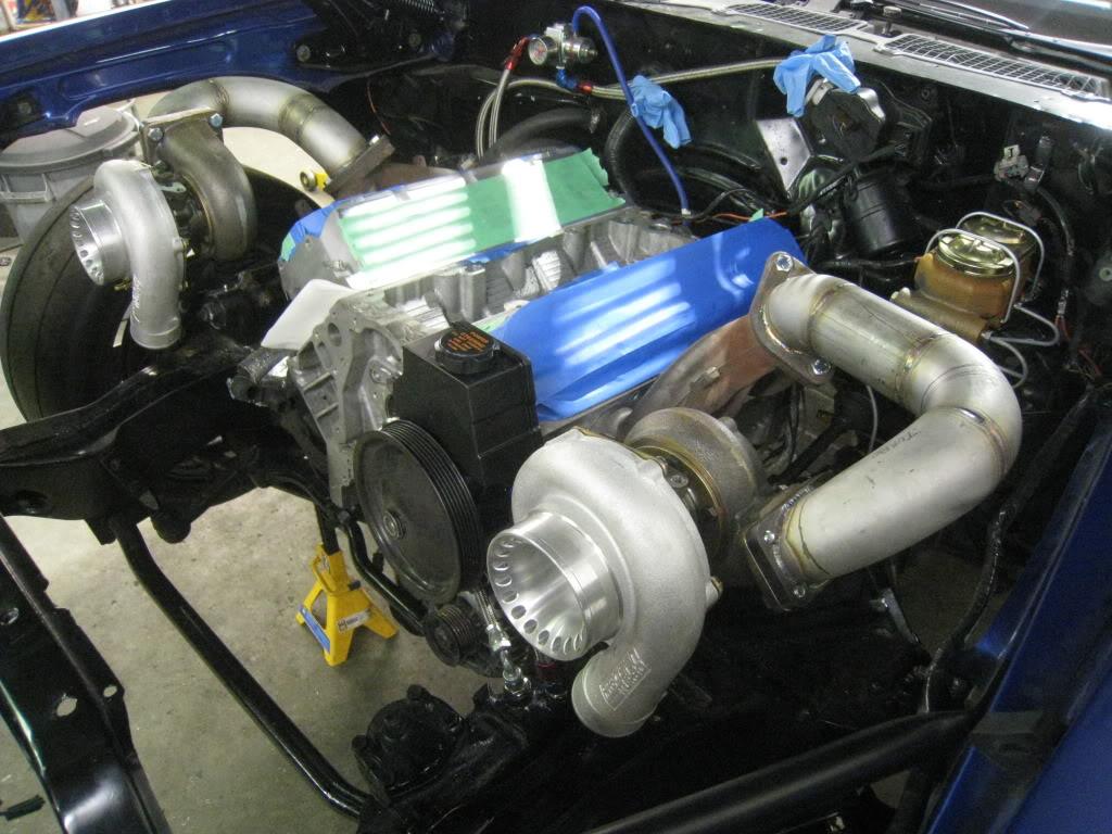
Building all forged 402, low compression, Precision hp 6265's w/.82 ar. Using 'vette manifolds.
7/25/2010
Just ordered my ARP main cap and head studs today along with an oil pump and oil filter sandwich plate for my oil cooler...$684... man the little things kill ya!!!
10/22/2010
I finally found the info I was looking for for a TMAP sensor for my Turbo build...
Cobalt ss TMAP sensor number 90423637 (2.5 BAR)
Pigtail for TMAP sensor number 88988320
Wiring Diagram
Borrowed this from NJHK at cobaltss.net.....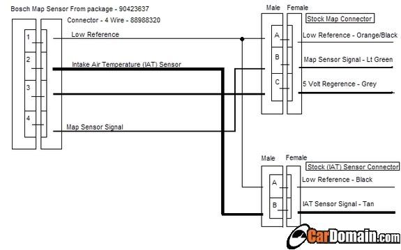
11/4/2010
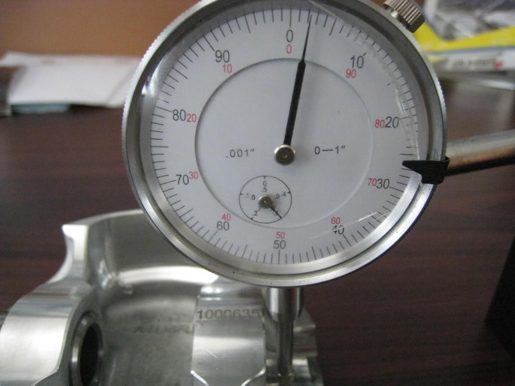
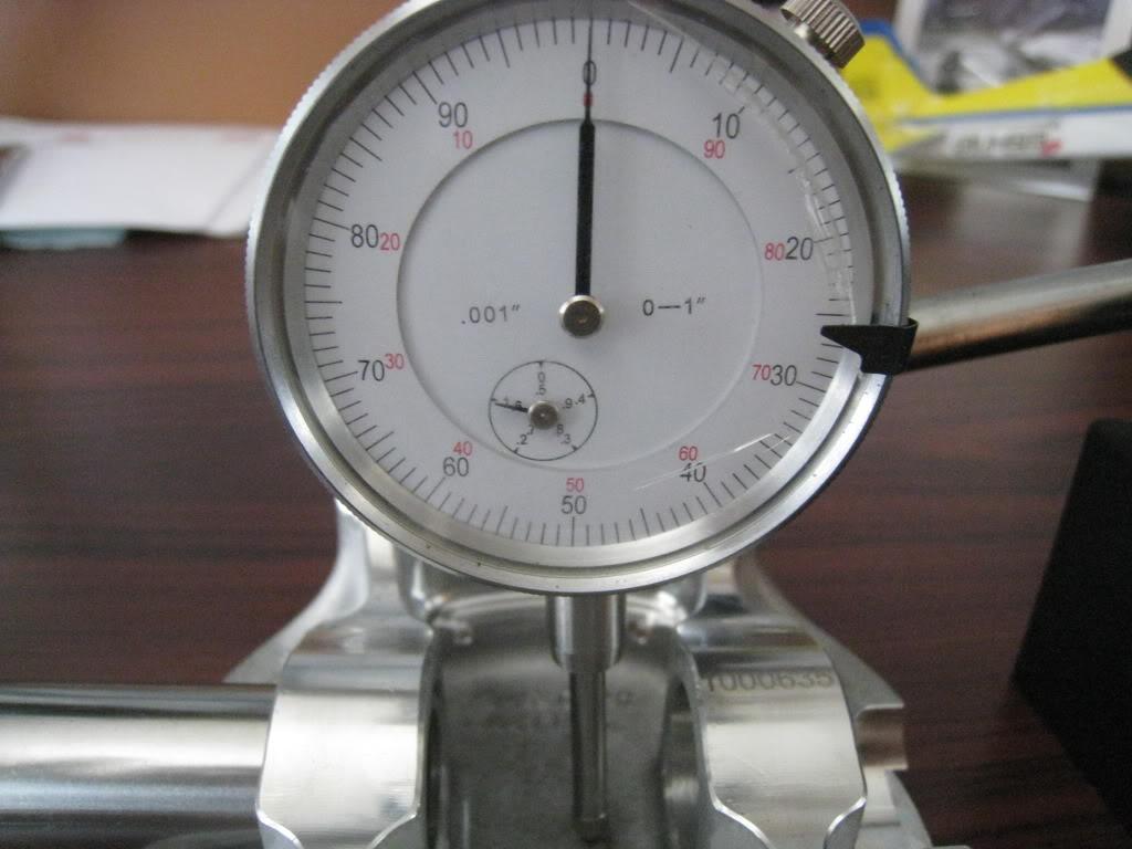
I'm assembling, or trying to assemble, the new motor. I got a Scat 4" stroker with H beam rods and -32cc dish racetec forged pistons. I was hanging the rods on the pistons when I ran into a snag. Has anyone ever seen this? The small end of the rod hits the underside of the piston. I measured and found that the clearance between the piston pin and the piston is the same or smaller than the size of the end of the rod. Weird huh? I have calls in to Scat and Racetec to figure this out. I will report back with the findings. Just goes to show that even when you buy all your parts from one place that are supposed to work together without machining, well, they don't. Measure everything!!! FYI there is supposed to be .050" clearance between the rod end and piston.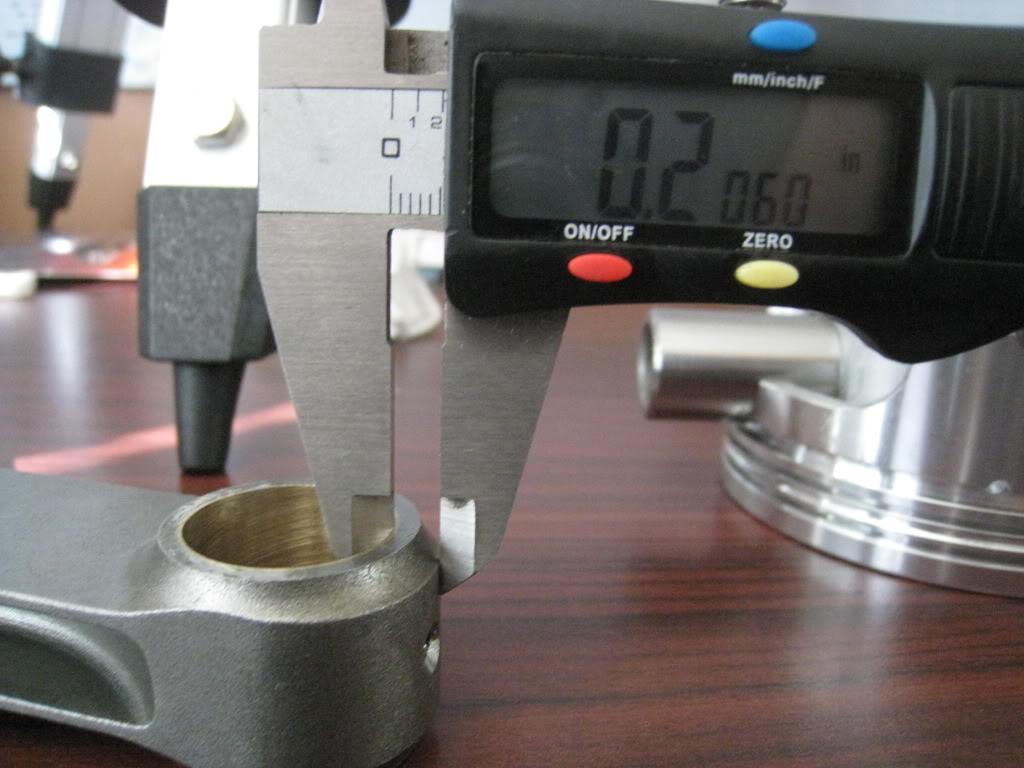
1/25/2011
Got the call from racetec. It seems somewhere along the line from where I initially ordered my rotating assembly from to actually receiving it someone sold me or included a piston set that was not reccommended for the numbers or boost that I am looking to achieve. Mike at Racetec was vigilant and realized this before sending back the wrong pistons I should be made aware of this. The pistons I had originally got were autotec brand, which are rated to a lower hp rating. He explained to me in great detail the differences and that he was first and foremost concerned that I have the correct parts, not just parts that would work, but parts that would last. Customer service is still alive and kicking in some places. Thanks Mike for showing me that. As far as the last piston issue, the engineers are addressing that as well, so others won't have this issue. He believes there may have been a forging issue there but don't quote me on that.
2/25/2011
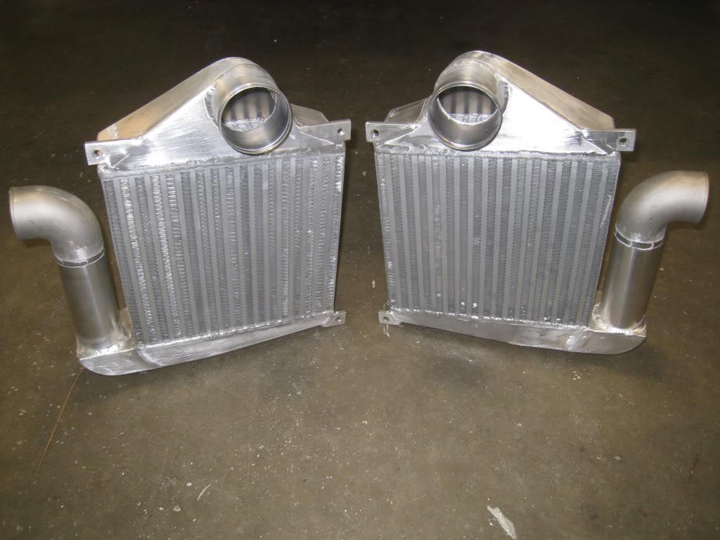
I decided to lower my radiator 3" so that I can put my intercooler piping over the top of the radiator and straight into the throttle body. On the procharger setup I used a side to side intercooler, but with the twin turbo's I decided to go with 2 seperate top to bottom 12"x12"x4" intercoolers (core size). I hope this doesn't end up getting filed under the "seemed like a good idea at the time" section. I've been taking lot's of pic's for this and will add them asap.
2/26/2011
Ok, so here's what I am starting with. This shot shows the space between the upper rad support and the hood. It's about 5/8" to 3/4" at best. The hood latch is in the lower left corner of this shot. It isn't stock as I had to fabricate that as well to accomodate the old intercooler. I may still have to do something else for the hood latch, but am holding out until I actually have the new intercoolers in hand to mock them up and see where everything fits.
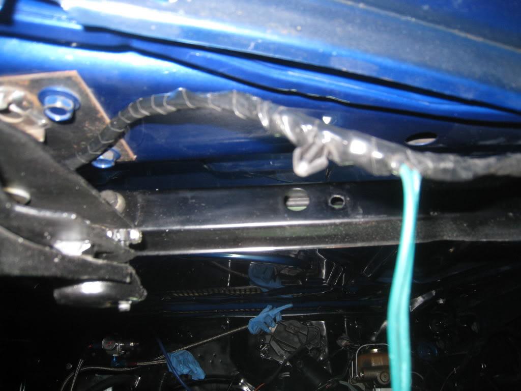
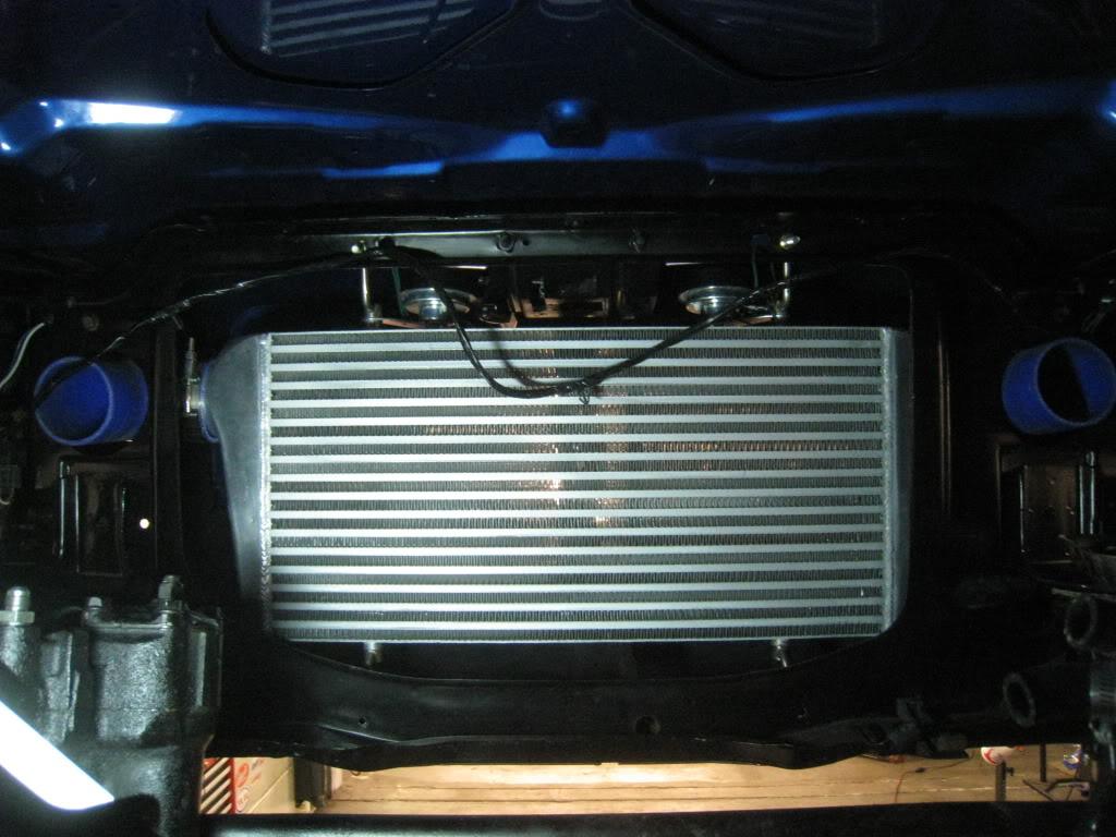
Here's the original intercooler. core size is 12"x24"x4"
Rad support
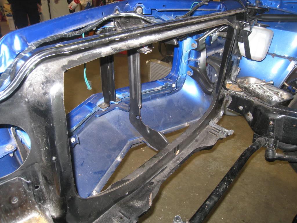
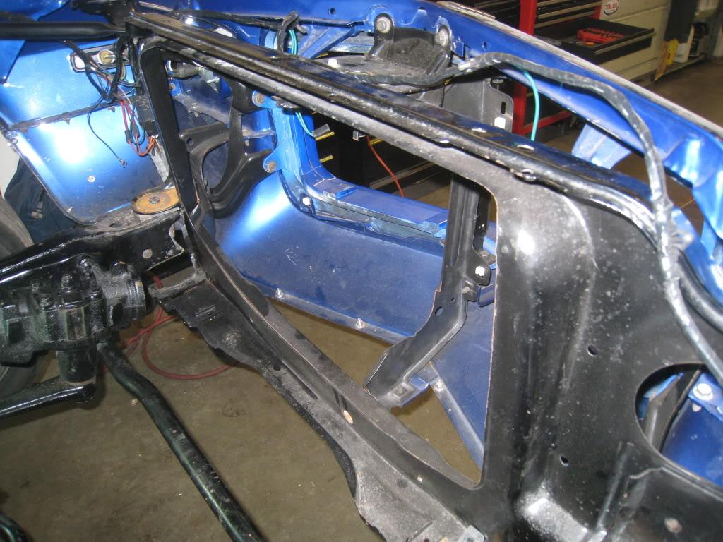
Here's what I cut out. I figured that I wanted to move my rad forward about 3" and down 3". This keeps it above the lip of the chin spoiler, and flush with the original rad support sheet metal after the formed part is cut out.
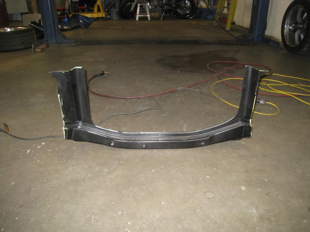
I removed the lower valance to cut out the rad support. Enter Sawzall!
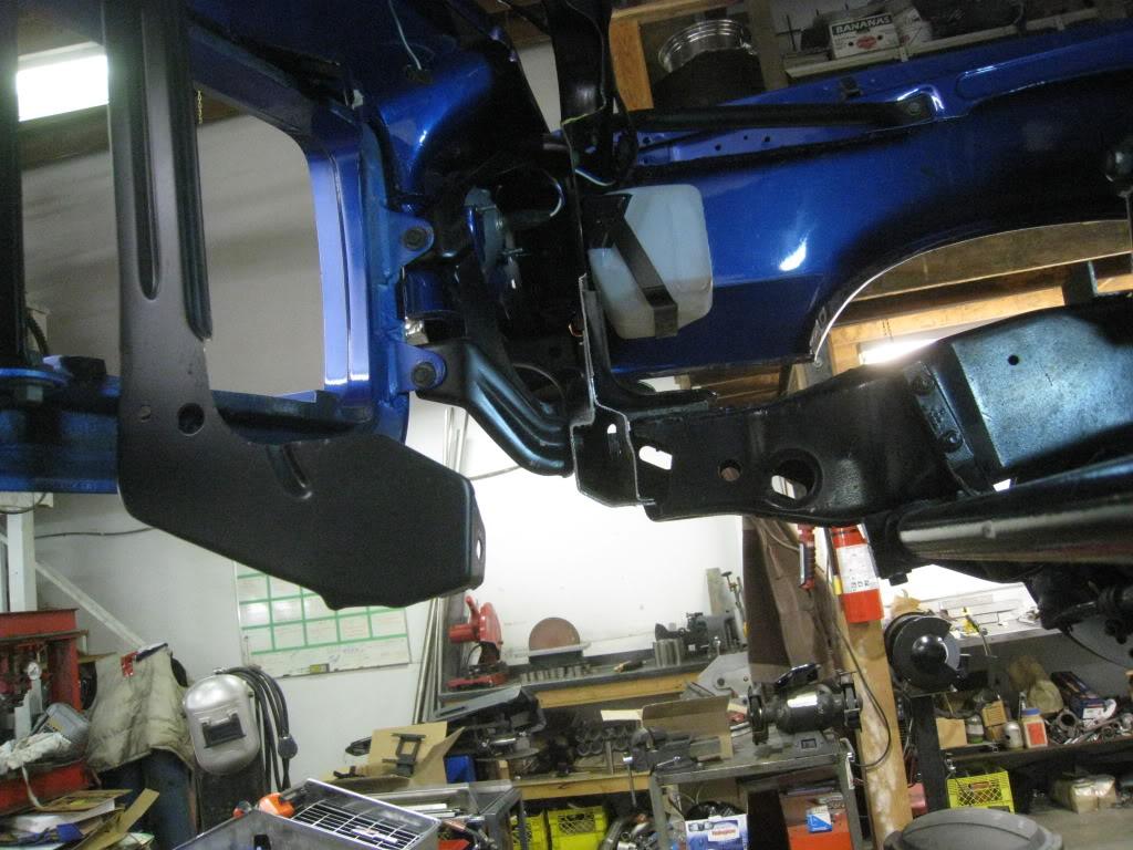
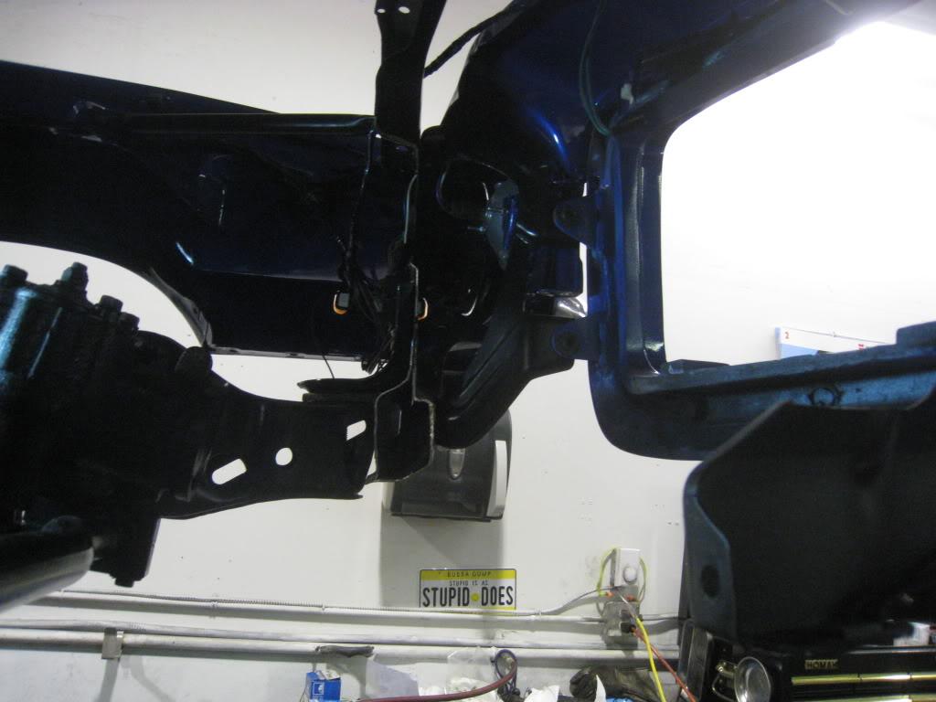
Next I used paper to trace out caps for the rad support frame ends. An easy way to do this which I use all the time is this. Hold a clean sheet of white paper over the shape you want to trace, and without moving the paper around too much, gently rub your dirty fingers across the paper over the edges of the object. I use this method when I need to make my own gaskets as well. In this case, I cut the tracing out through the middle of the image and then transferred the paper to 18 guage steel.
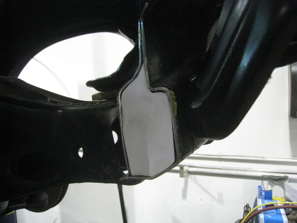
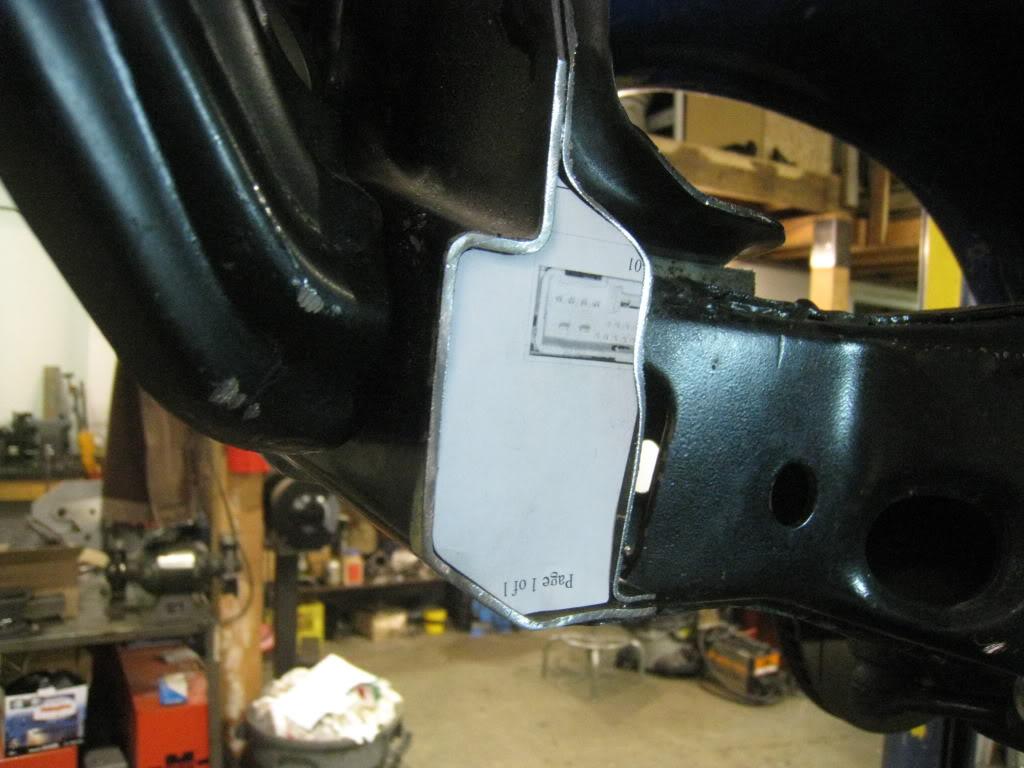
Steel caps tig welded in
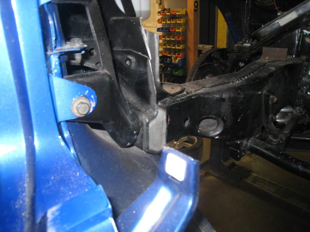
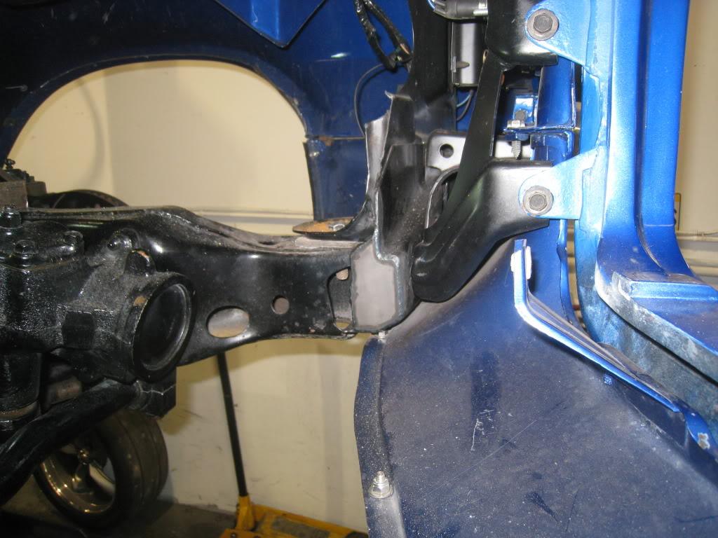
3/1/2011
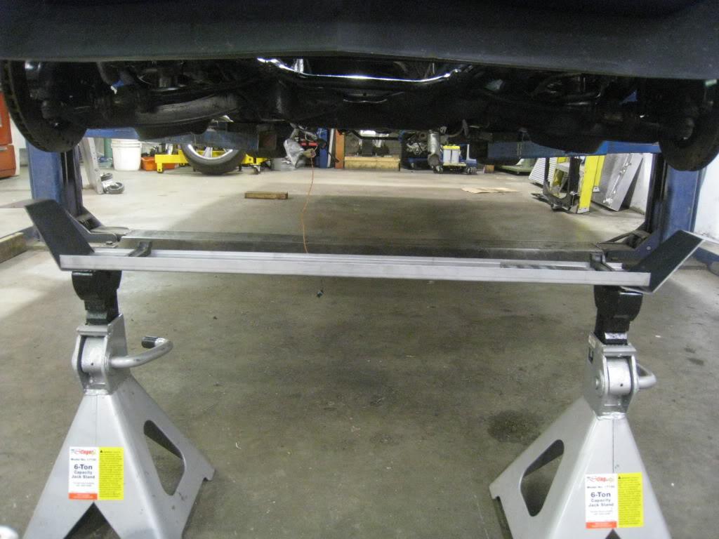
A little more progress... I took some 18 guage steel and formed it to hold the original rubber saddles. I then drilled 1/4" holes in the appropriate spots to locate the rubbers. I put the radiator in place on top of a pair of jackstands and lowered the car until I found my desired clearance. I used some welding rod and bent it to give me a guide for making the drop down brackets to support the formed piece. I cut these out of 14 guage. formed them and checked out the fit. I will be mounting these from the bottom bolted into the front subframe. I decided to stop at this point and wait until I can mock up the intercoolers just to be sure everything fits before welding anything.

3/2/2011
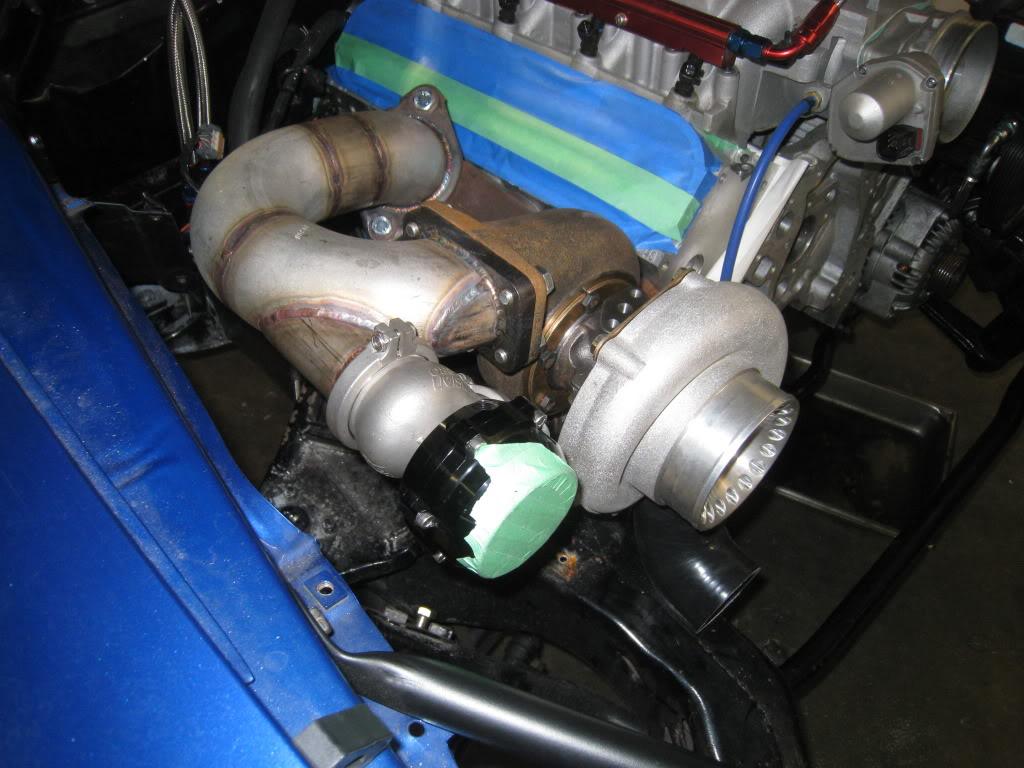
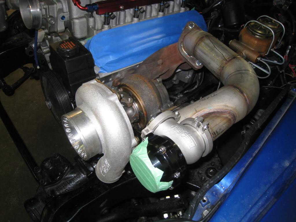
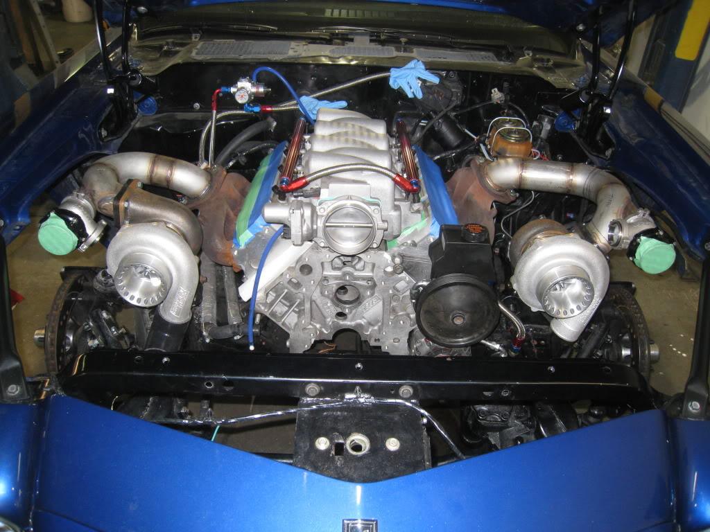
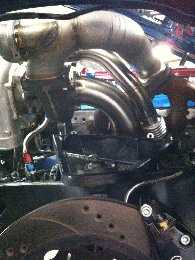
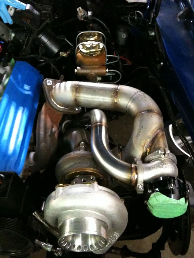
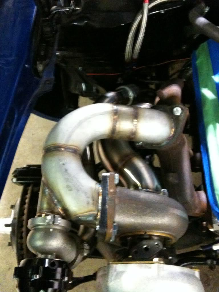
Got some work done today on the turbo to manifold pipes. I am using schedule 10 2.5" stainless steel pipe for these. As always a big thanks goes out to Mike and Ryan at Custom Metalcraft.
Turbos mocked up, passenger side was the more difficult side, so did that first.
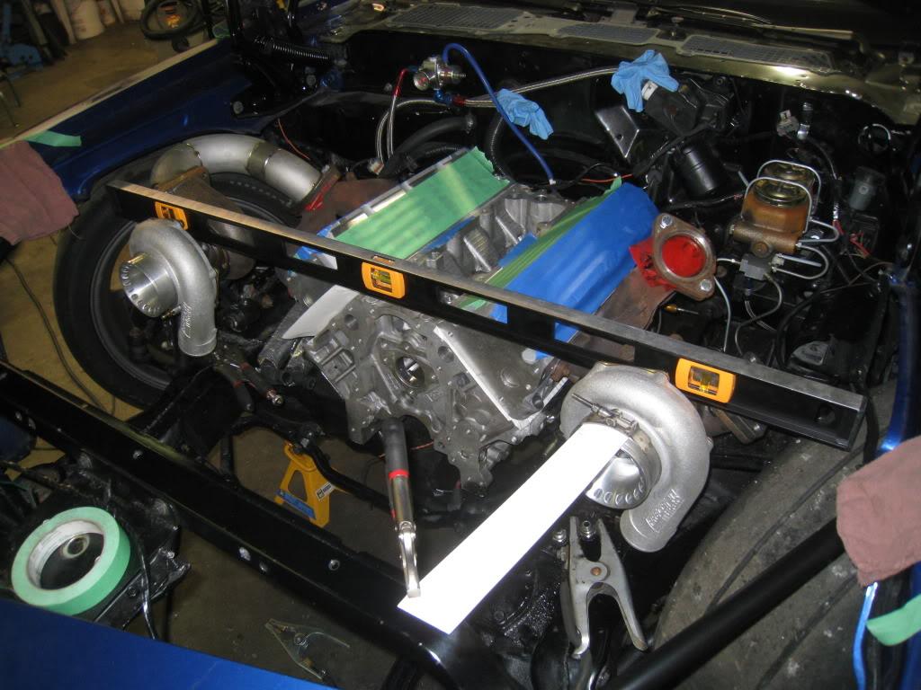
Some various pics of the process.

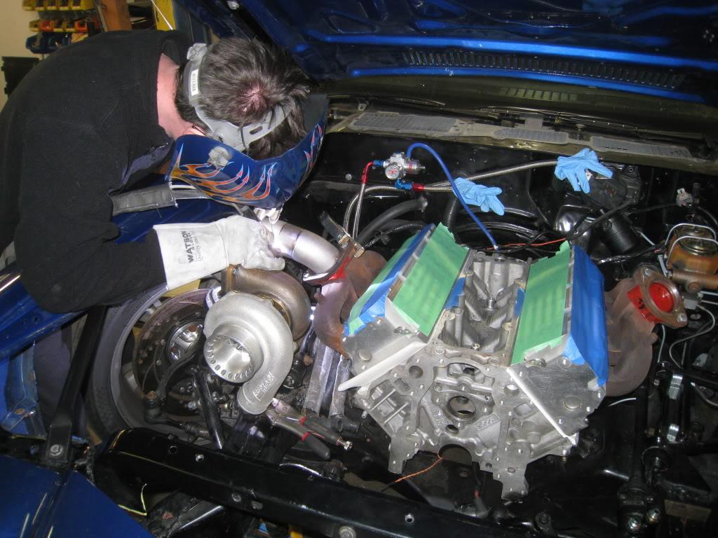
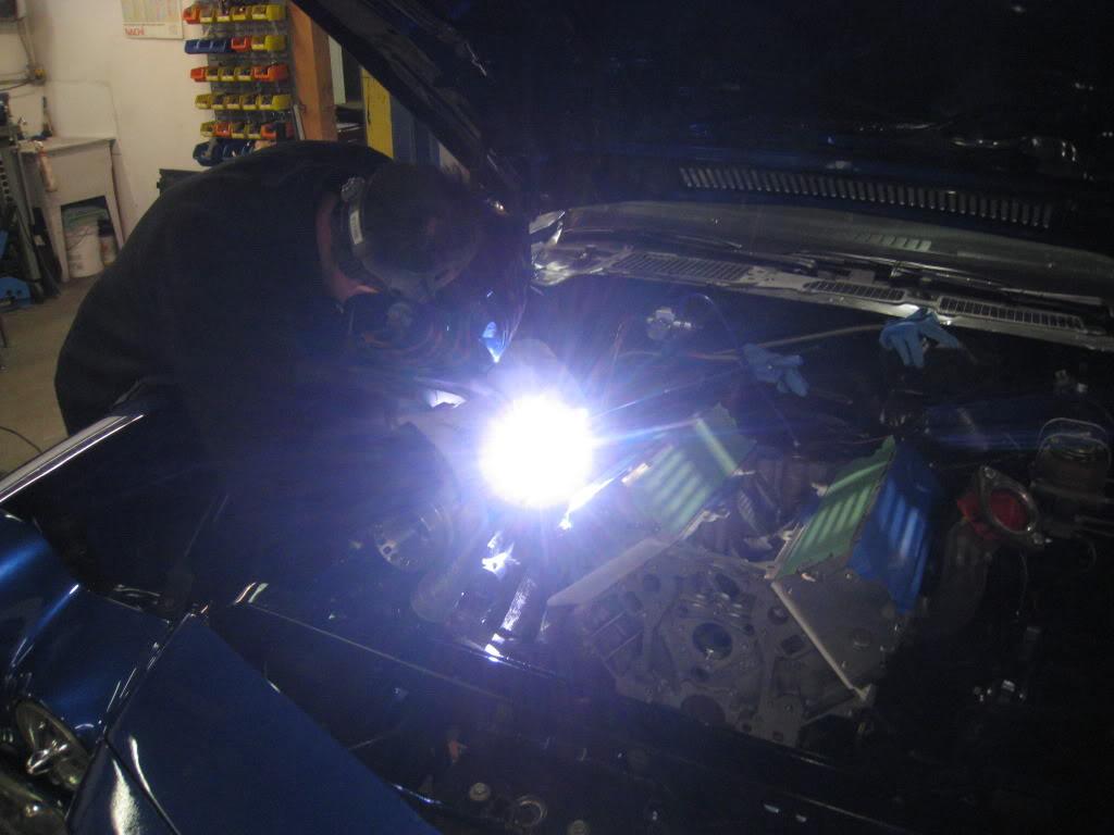
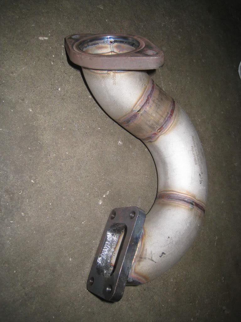
I did all the mock up with the springs removed from the front suspension, and the wheels on and jacked up to bottomoed out with the wheel turned both ways to be sure there would be no clearance issues later. I will be making my own inner fenders. I also continually checked the clearance to the hood.

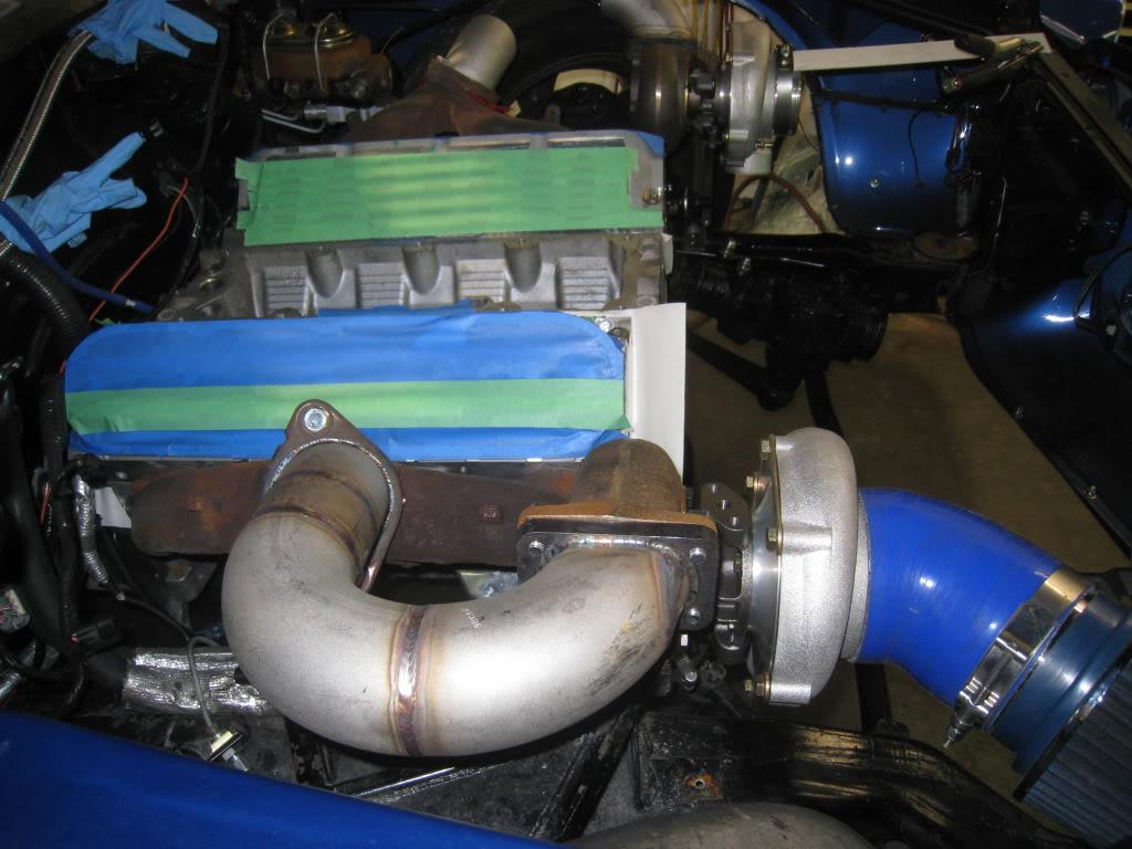
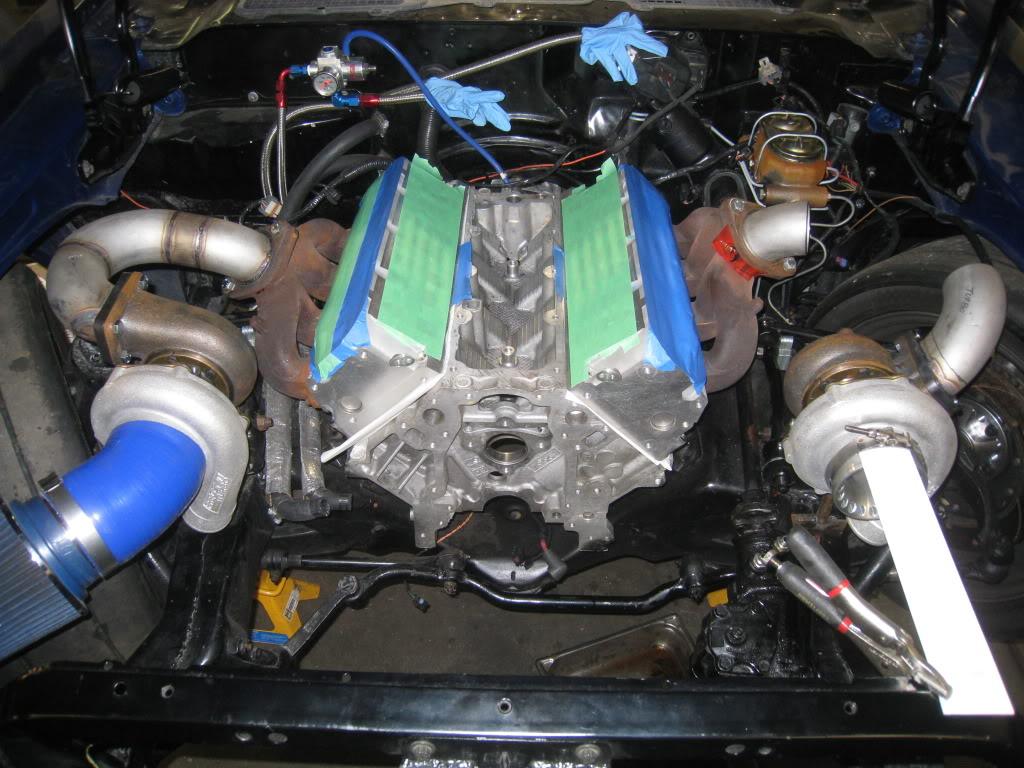
Its not all good, I'm broke. I can only do this stuff because I pre-bought all the parts when I was working. ***Lesson to be learned??? Stock up while you can!***
Some more pics...
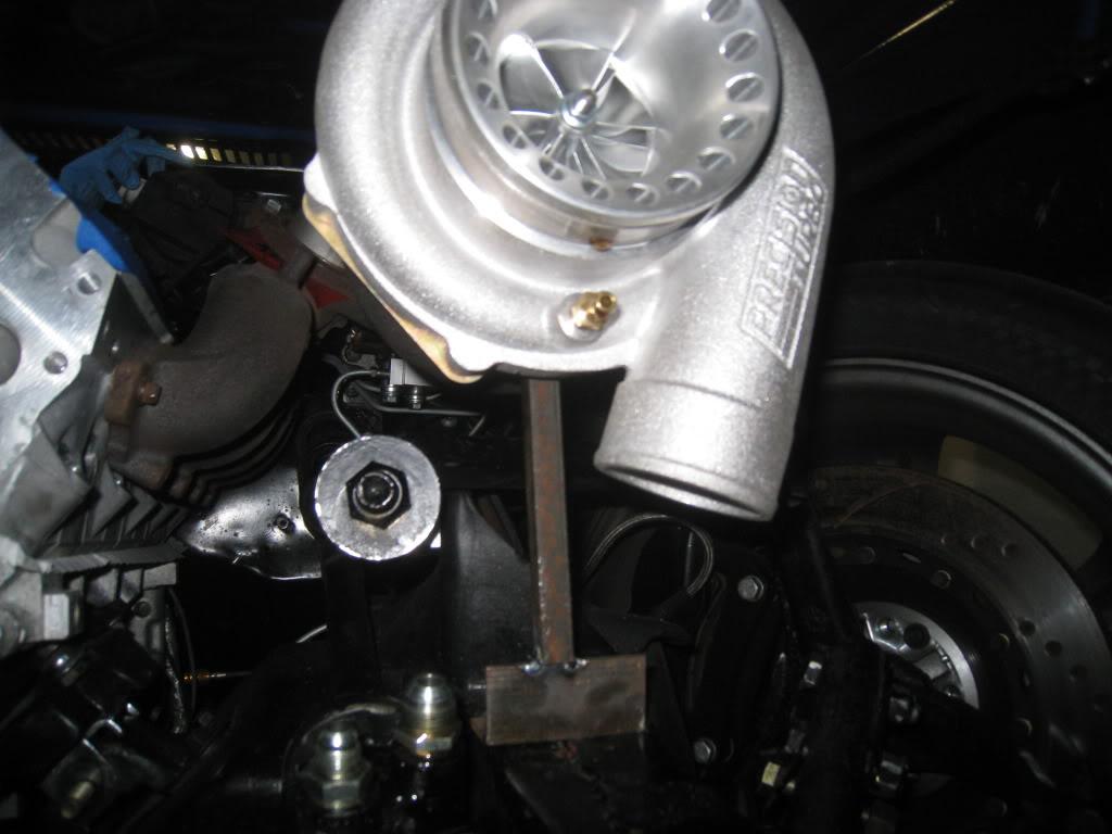
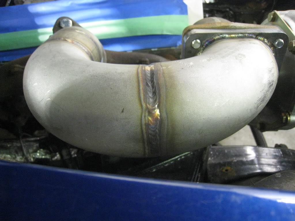
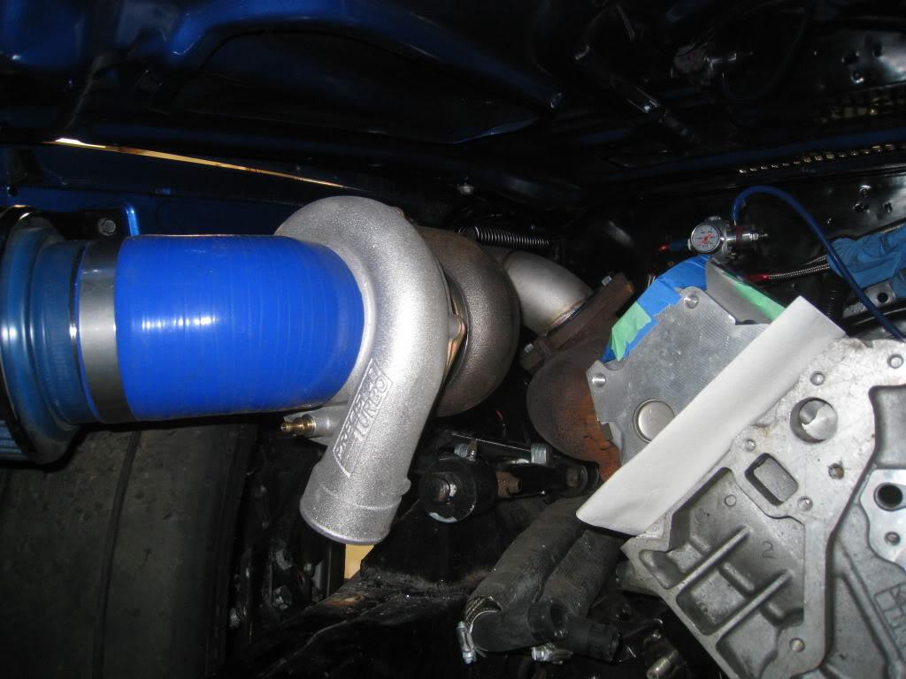
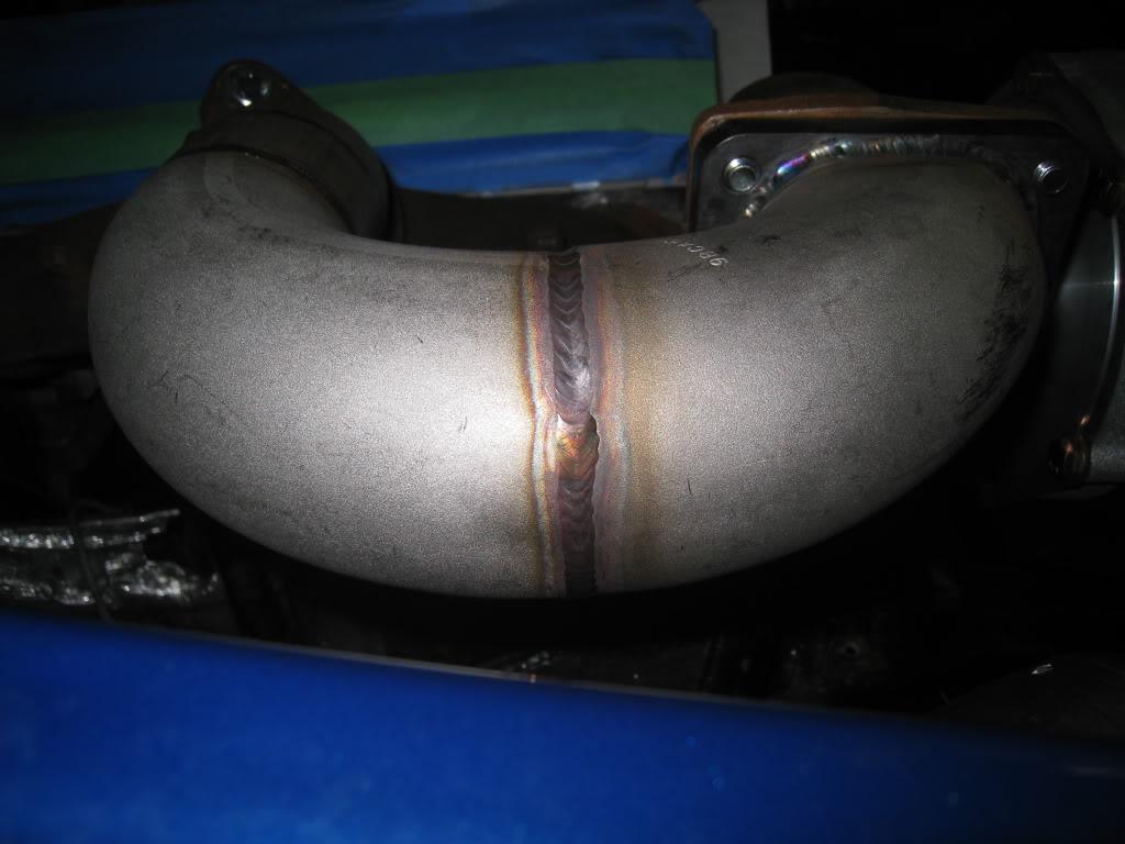
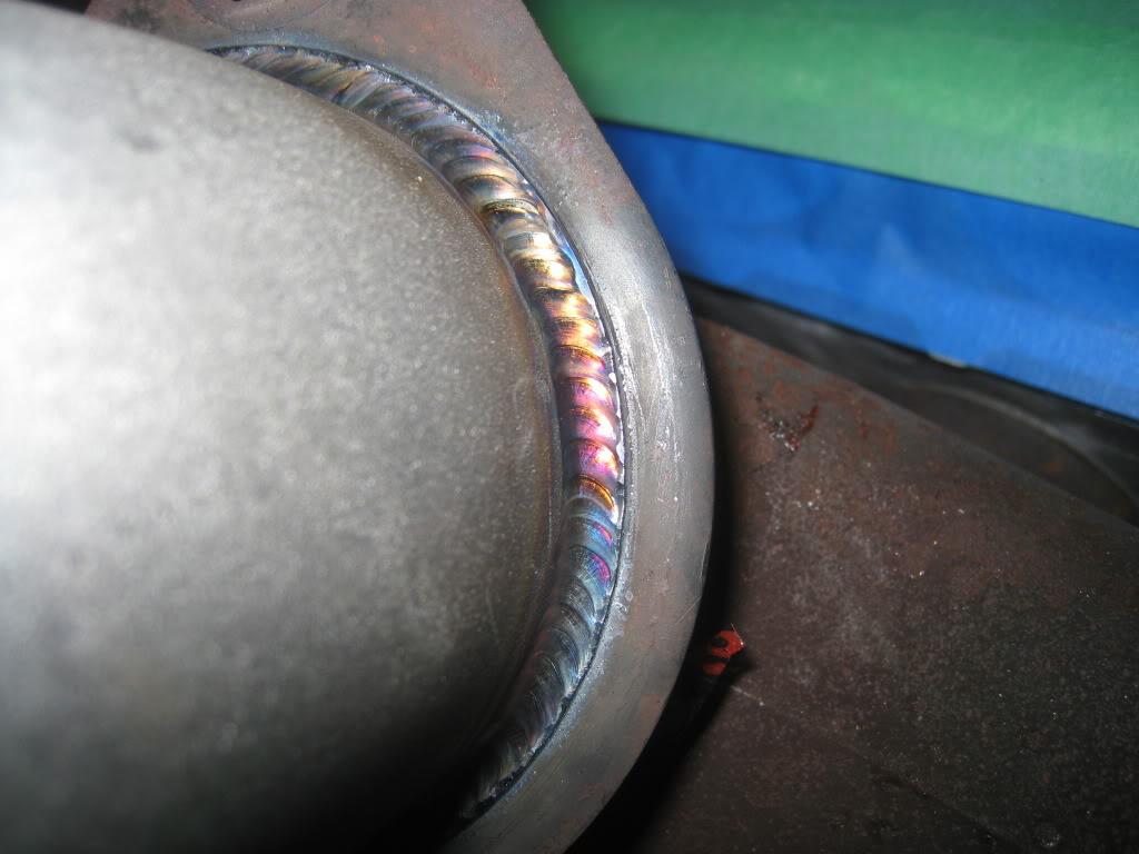
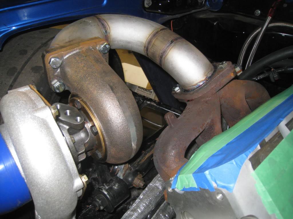
Trying to figure out exactly where to put the wastegates. These are Precision Turbo 46mm units.
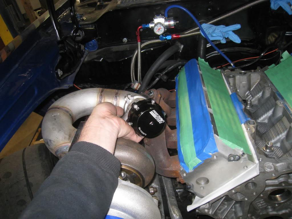
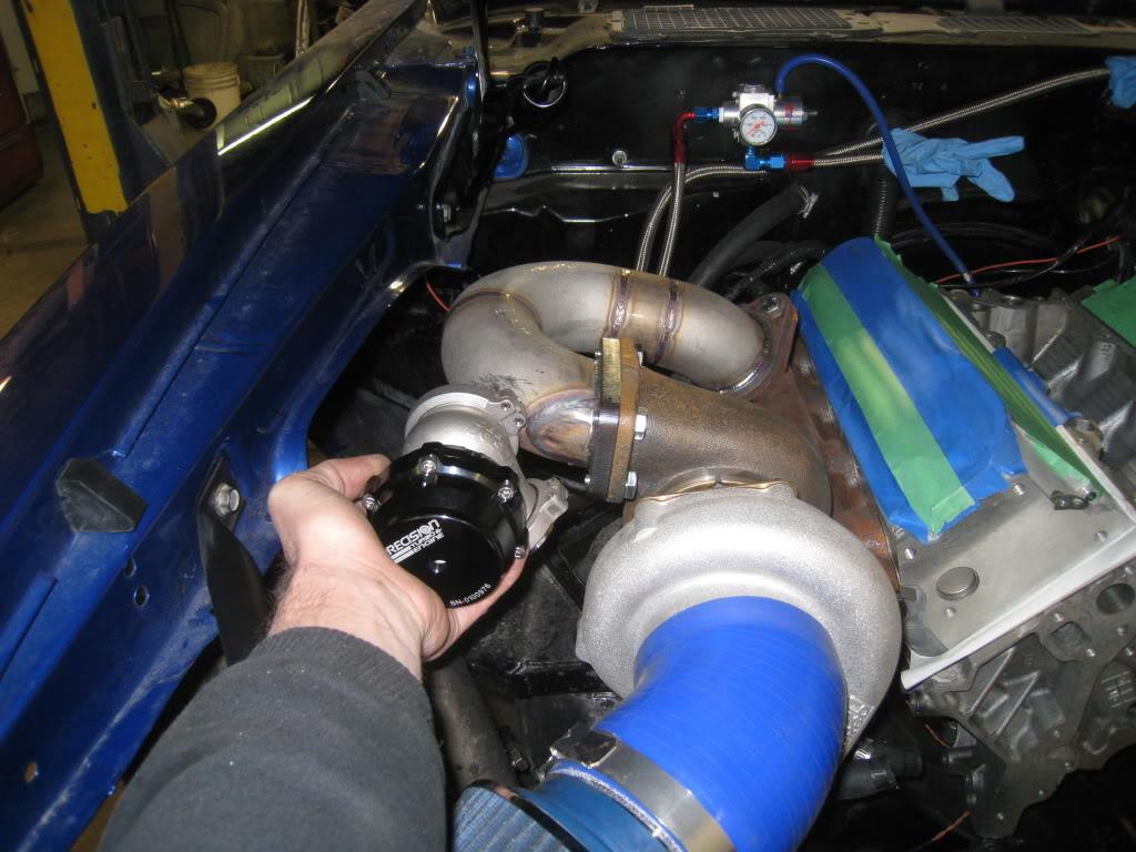
3/3/2011
I got the other side done today... YAY!!! I ran into an issue with my pipe though. Trying to find schedule 10, 2.5" stainless steel straight pipe was tough. Especially when you only need 6 inches of it. So tough that no one had it. One guy could get it, but I would have to buy a 20 foot length and he would still have to order it. Solution? Bought 6 inches of schedule 40, 2.5" pipe and spent a good hour on the lathe boring it out. Problem solved.
Pipe in lathe
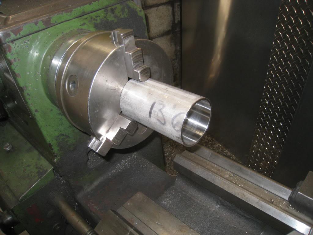
Drivers side pipe before final welding
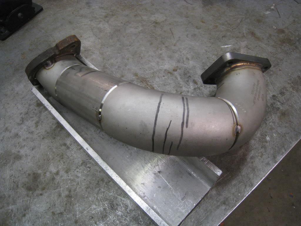
All mocked up
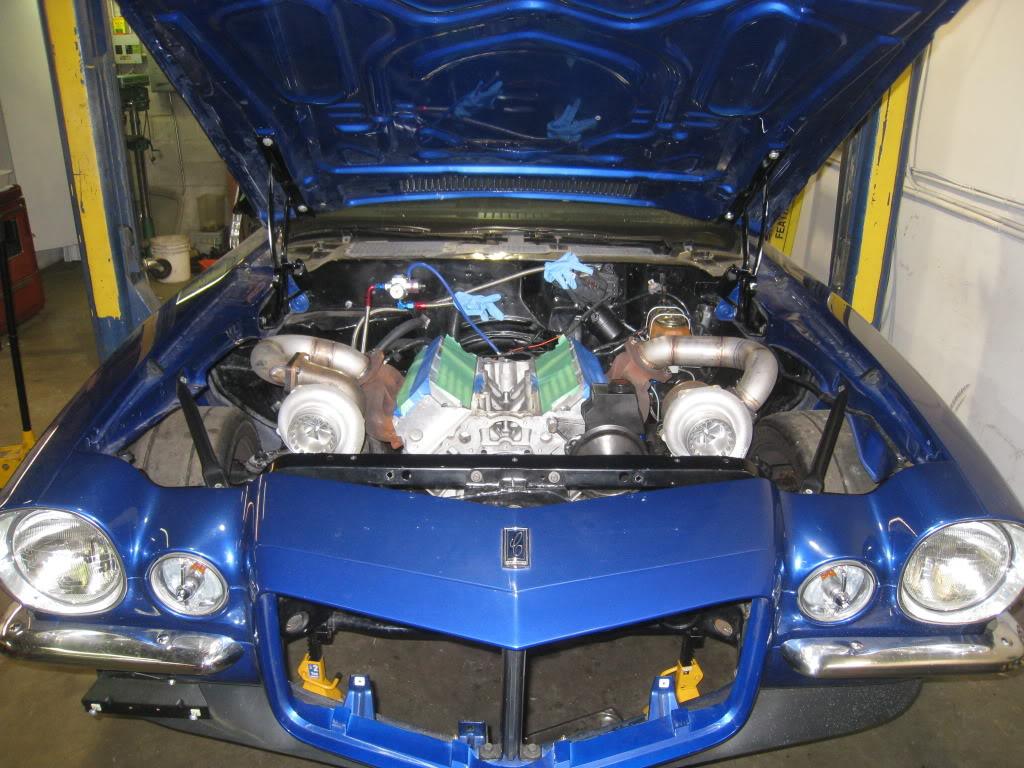
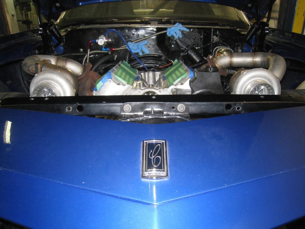
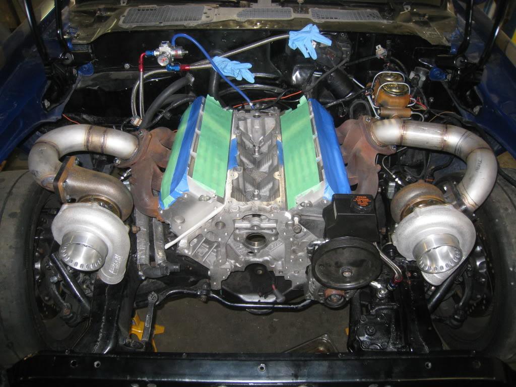
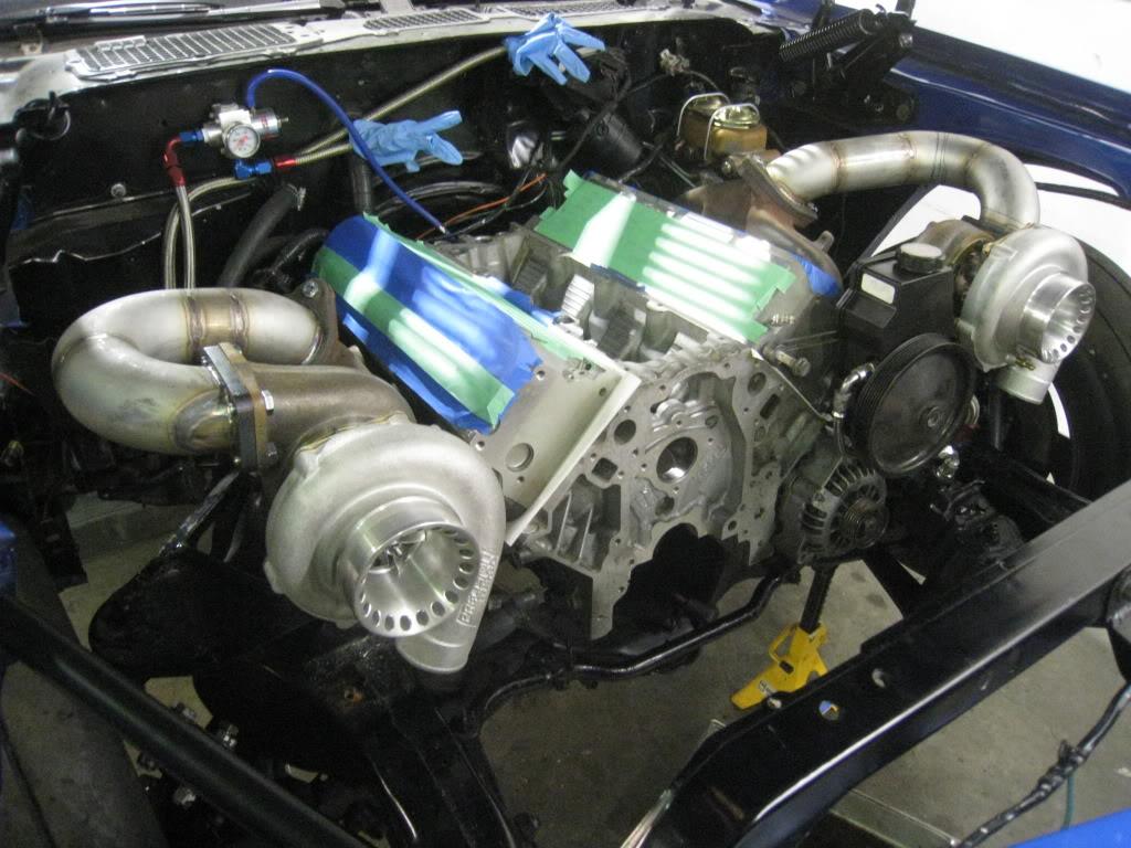
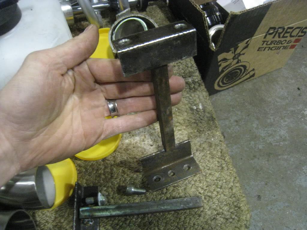
The stands I made to hold the turbo's in place while building pipe
3/9/2011
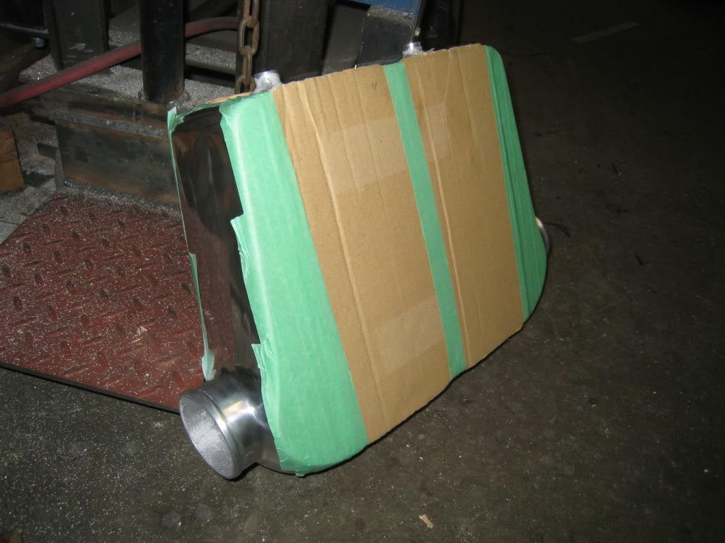
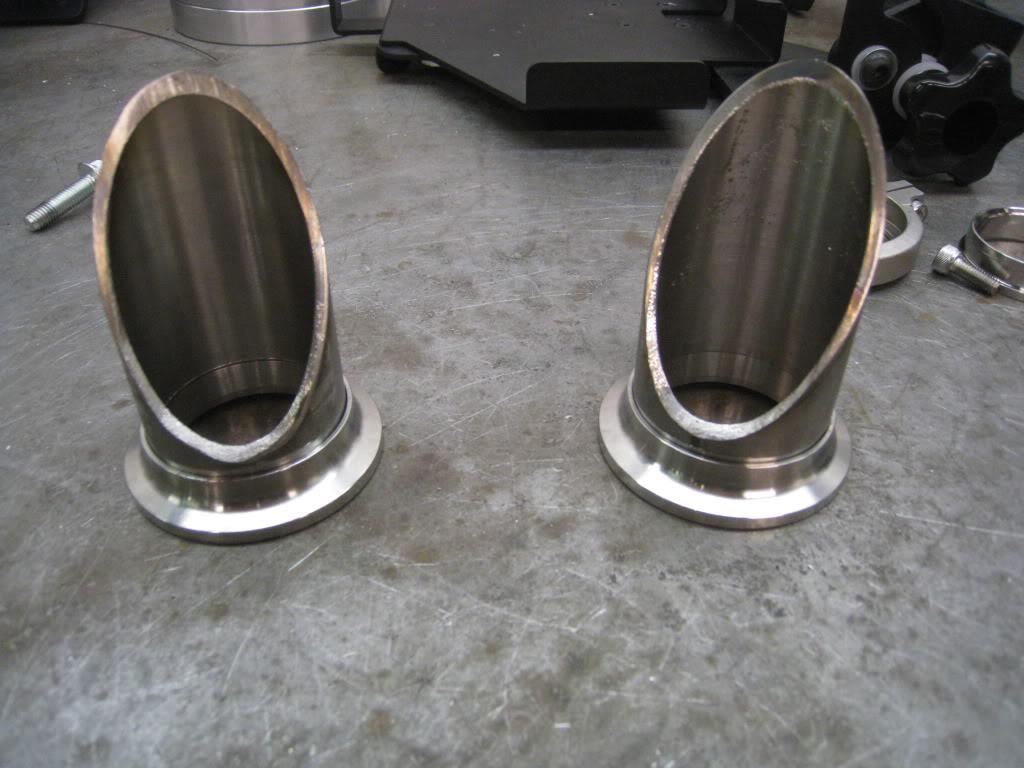
Thanks everyone! This build has been, more than anything, a test of patience. I received my intercoolers and pipe today. Opened the box and guess what?... Only 1 intercooler. Here I am waiting some more. Anyway, got some work done but today was one of those whole lot of nothing days. I prepped the 1 intercooler I did get for modifications. I cut off the outlets and looked at where they, er, it, will go. Looks like things may work out ok there without removing my hood latch. I'll see after I have both intercoolers. I am still waiting for the turbo outlet exhaust flanges so couldn't work on the down pipes, but did start the process of installing the wastegates. Again didn't have any schedule 10 1.5" stainless so had to bore out schedule 40. Getting pretty quick at that but am also really sick of it. Got the spot figured out on the hot side of the turbo pipe and am really happy with where it is going to be. Should have pics of that tomorrow. For now here's the intercooler, and the 2 flanges ready for welding.
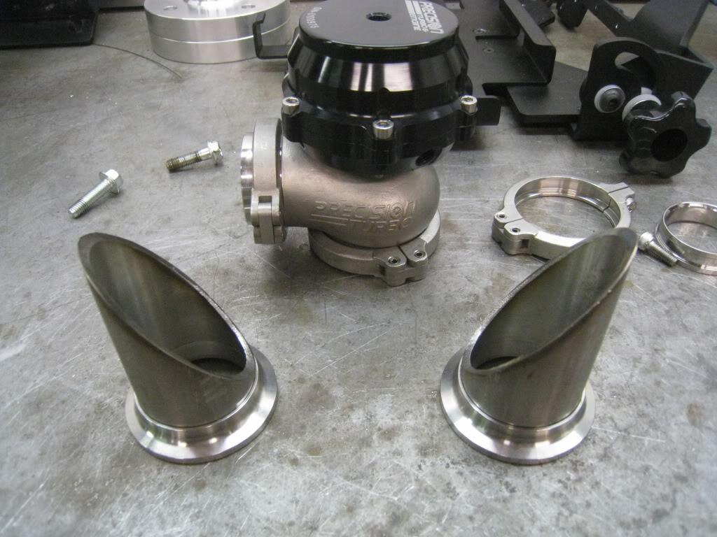
3/10/2011
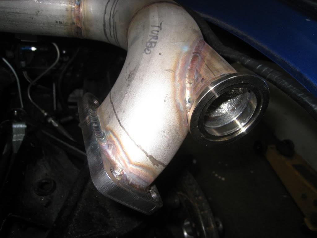
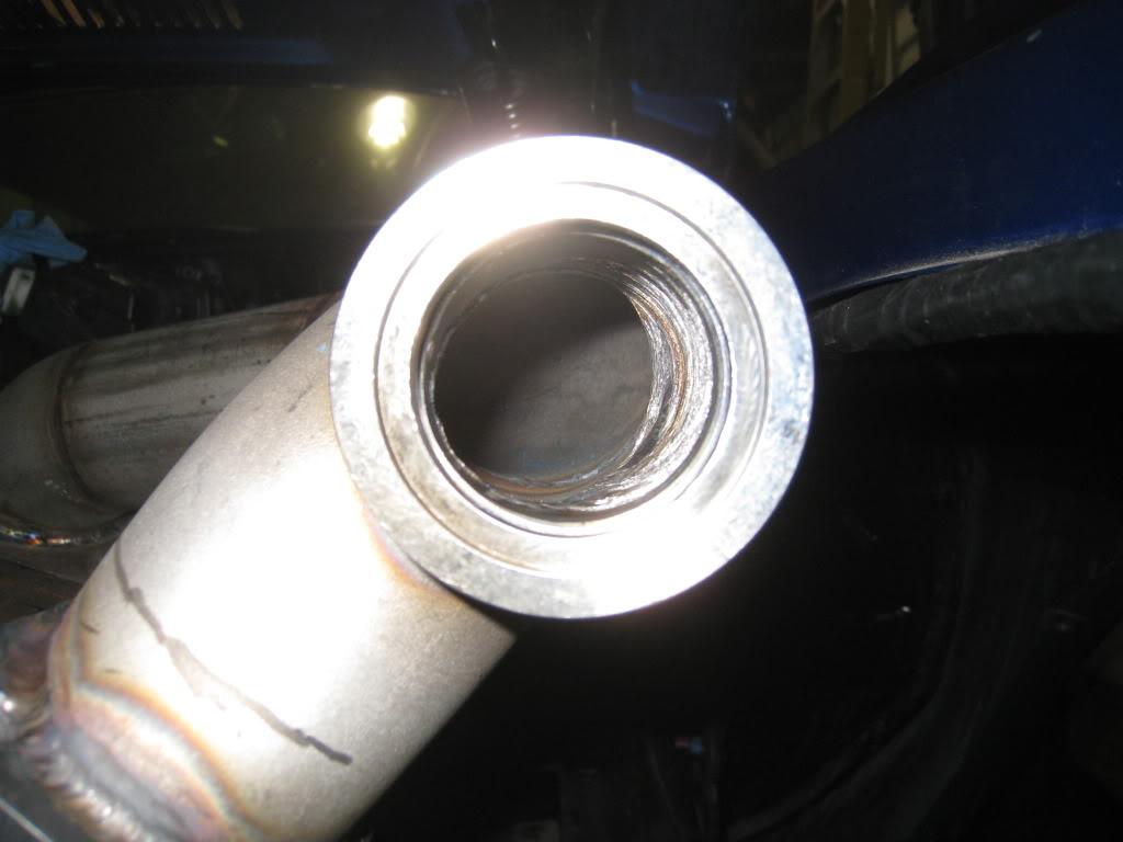
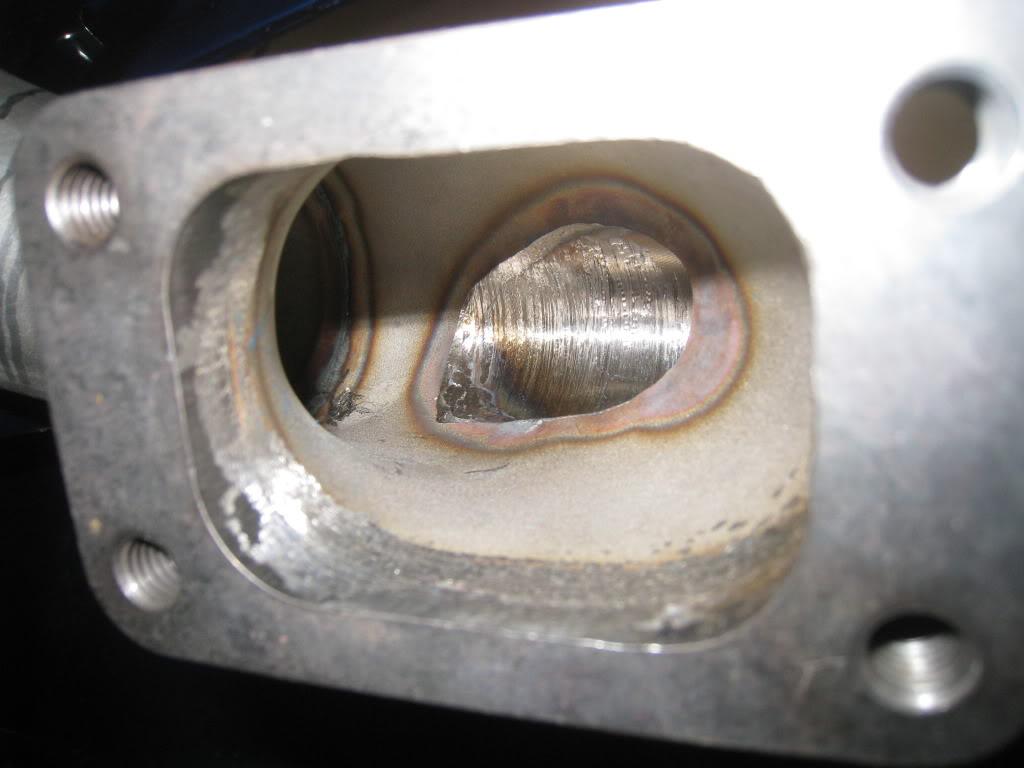
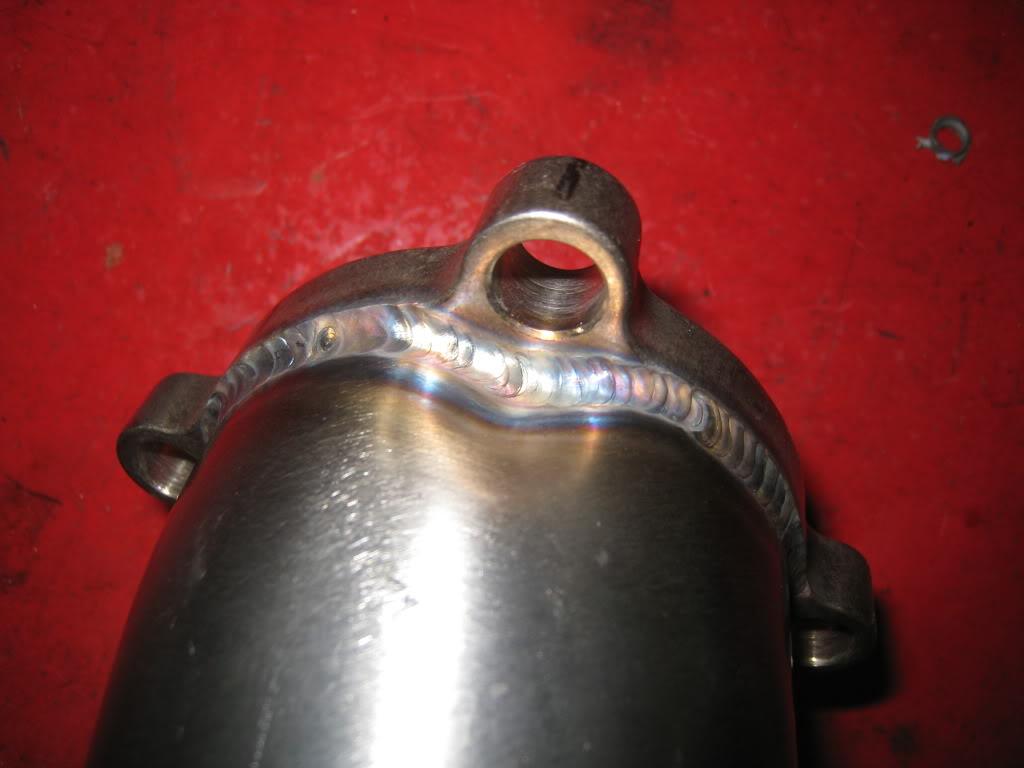
Mounted the wastegates today and built 1 downpipe. After the spiggot was welded onto the main pipe, I just ran a holesaw through the middle, then cleaned it up with a carbide bit die grinder.
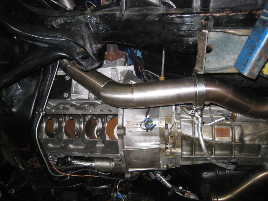
3/11/2011
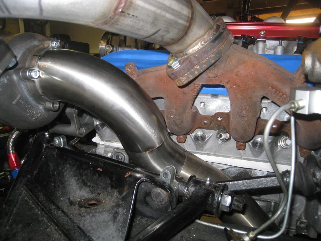
Completed the down pipes today. Just the dump pipes left to go on the hot side then it's on to the intercooler pipes.
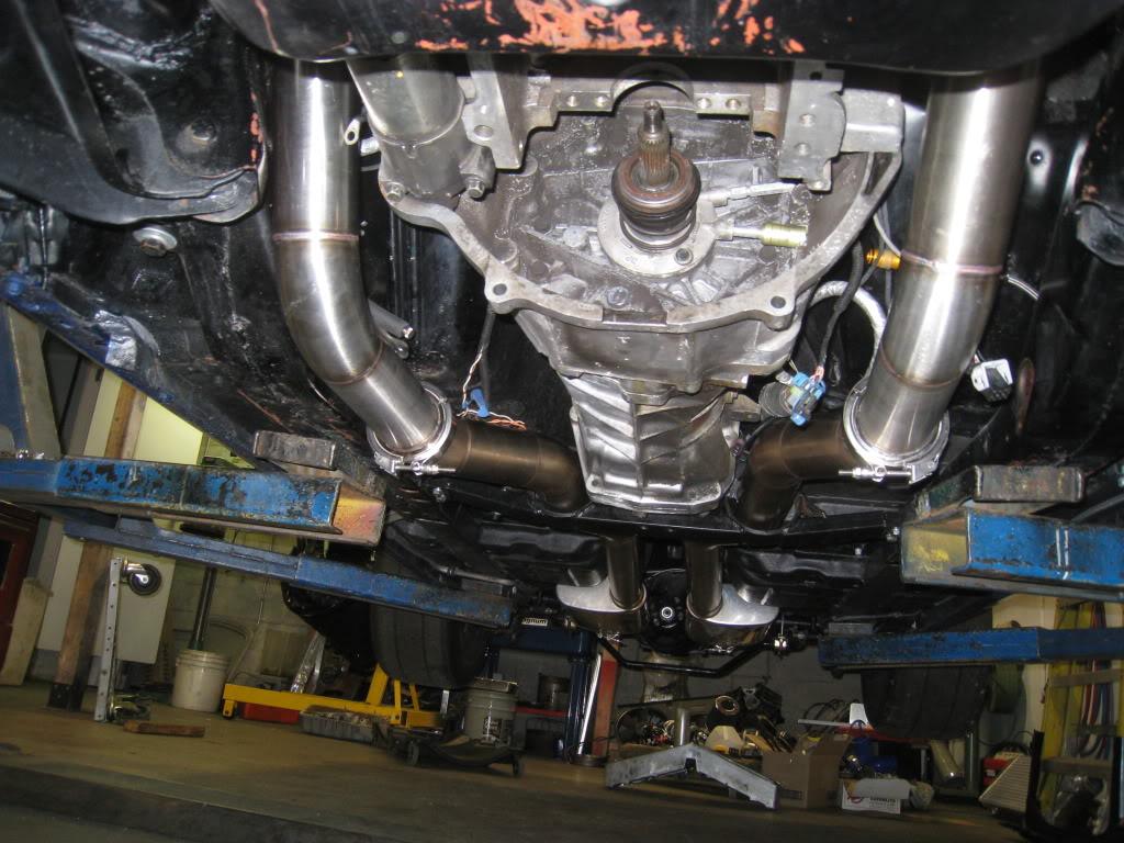
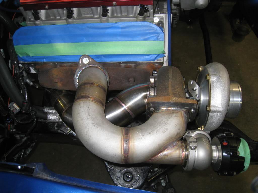
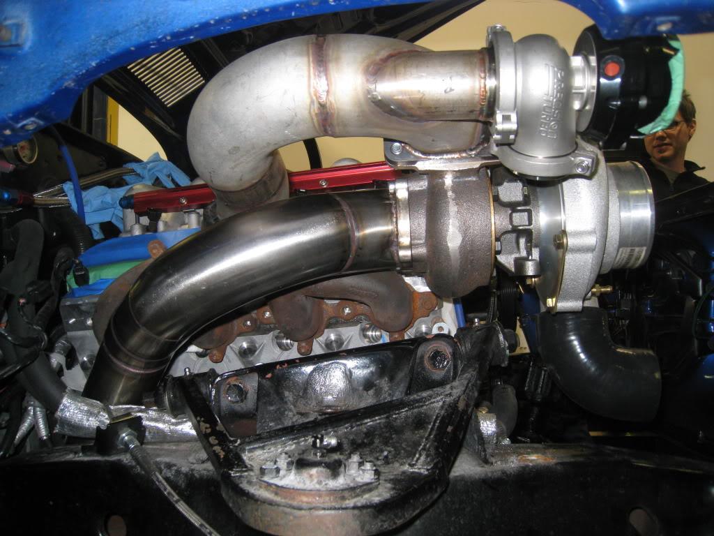

3/16/2011
Hot side complete!!!
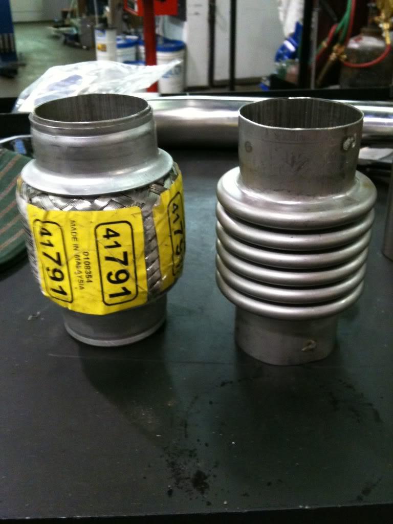
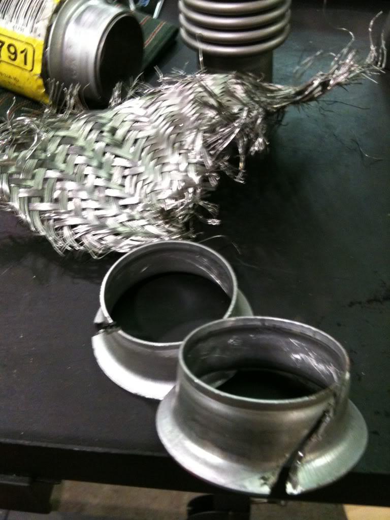
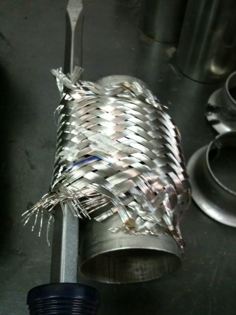
I finished the hot side of the turbo setup today. I needed some 1.75" flex pipes for the waste gate dump tubes. Vibrant makes them but there were none available locally, and they retail here at $58ea + $10 shipping. So, I thought, Hmmmm, I wonder whats inside those normal flex joints that are wrapped in braided stainless? I figured I could risk the $17ea, and at least cut one up and see. As soon as it arrived I looked inside it and it looked very similar to the Vibrant piece. Checked it with a magnet tool and sure enough, not sticky (=stainless steel). So I cut it up. The clamp rings on these are just crimped on so using a cutoff wheel I carefully broke the tension ring. I didn't cut all the way through, just most, then using a big screwdriver not to pry but to twist between the cut lines, it just popped the remaining steel and the ring slid off easily. The stainless wrap. I slid the big screwdriver under the skin then cutting disked through the wrap being carefull not to go too deep. the wrap is held in palce with a few spot welds, so I cut the wire with cutters, then dressed them clean with a grinder / dremmel.
Here's where the dump pipes re-enter the exhaust down pipes. I used a hole saw after tracing out where the pipes meet. Then fine tuned it with a carbide and a file.
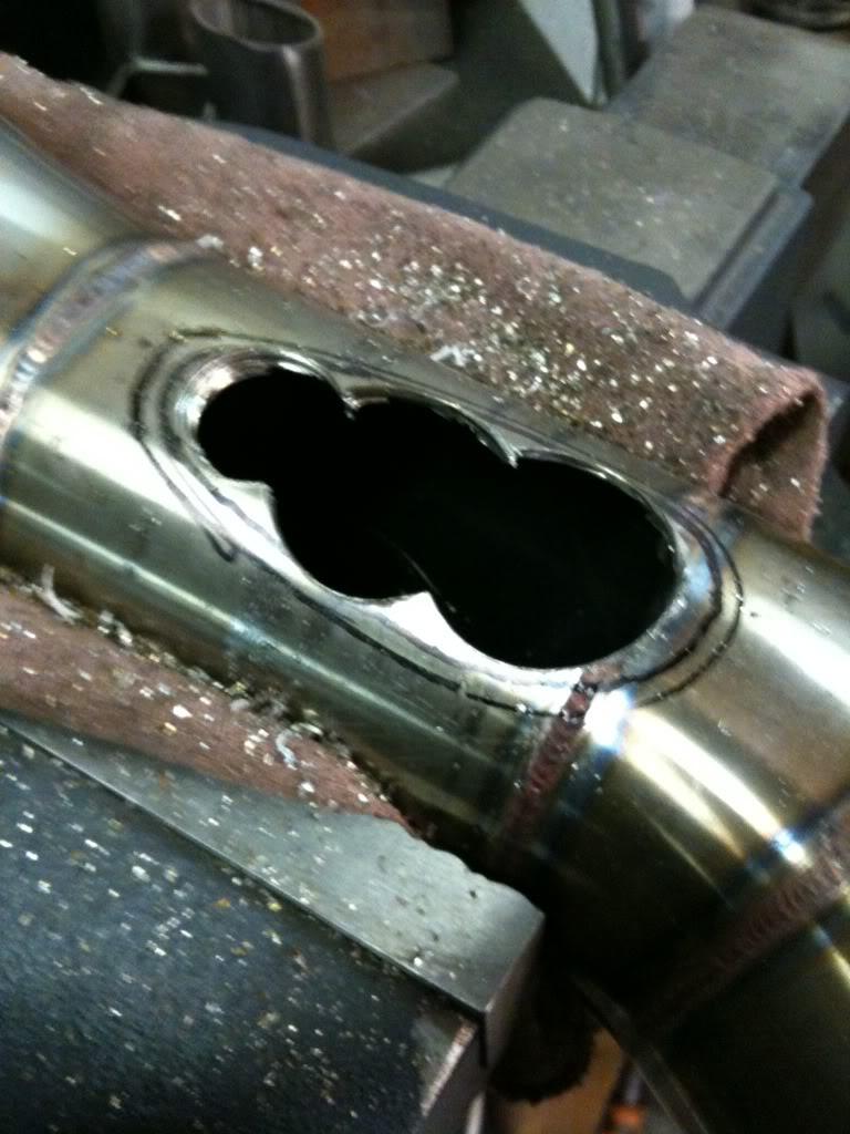
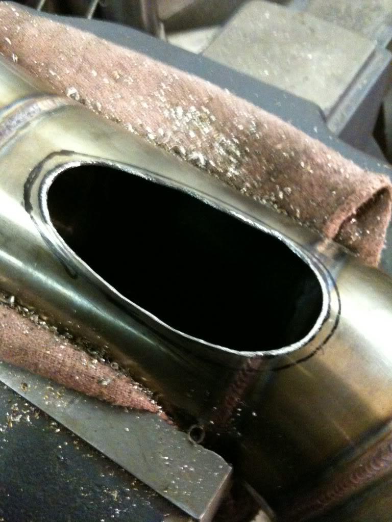
All welded up
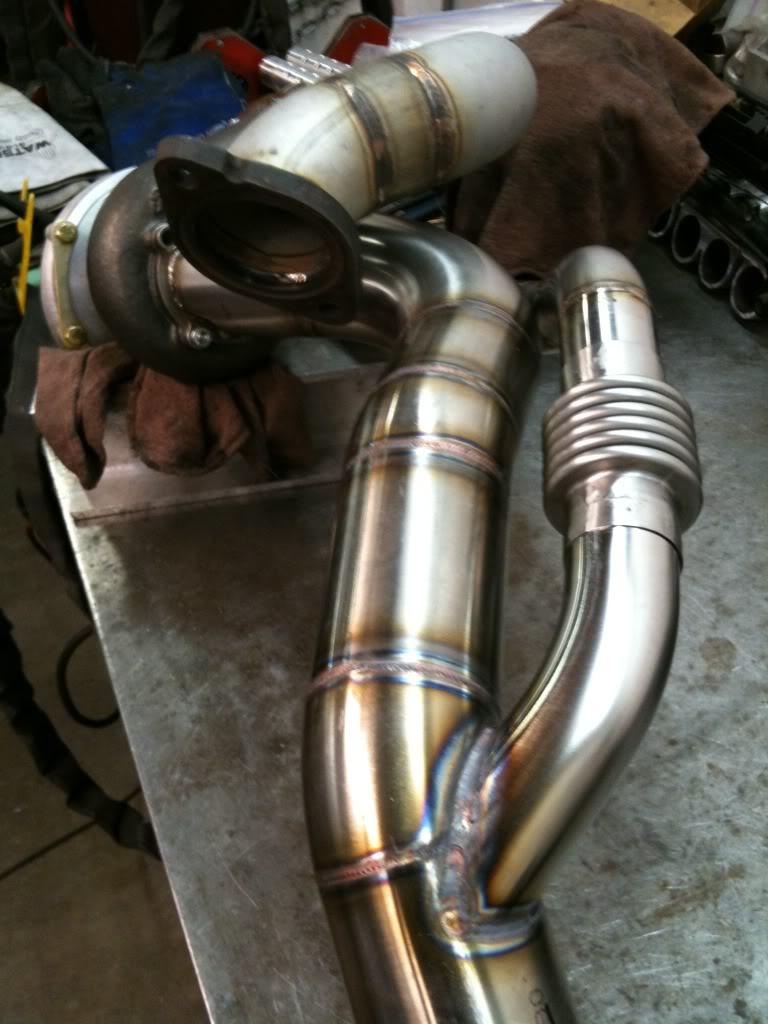
Installed
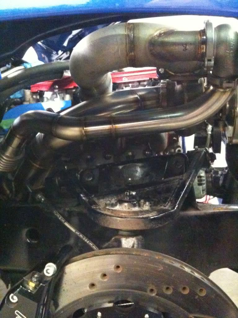
3/24/2011
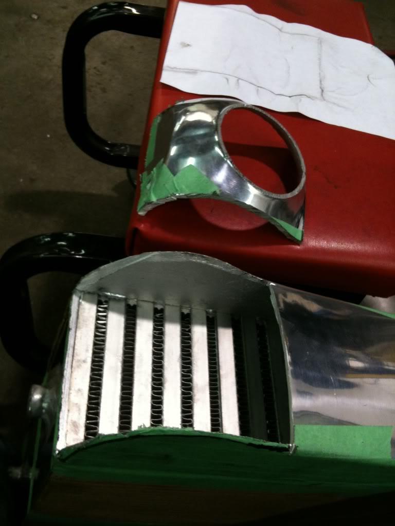
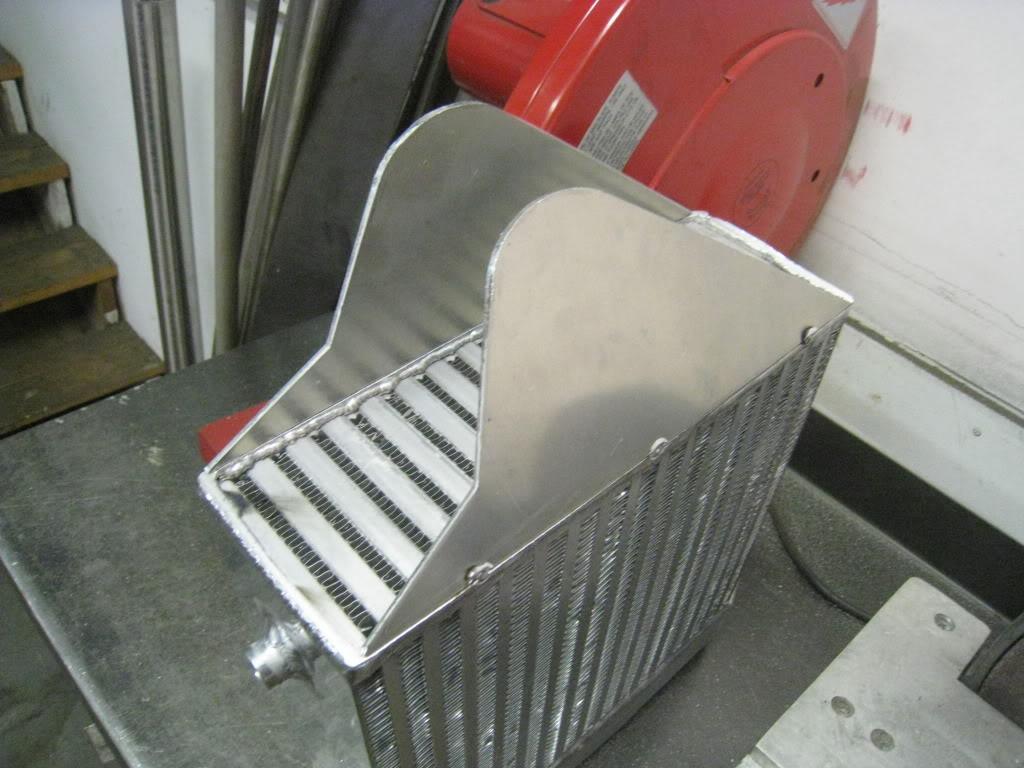
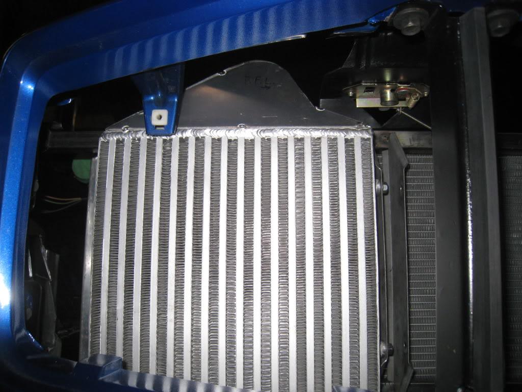
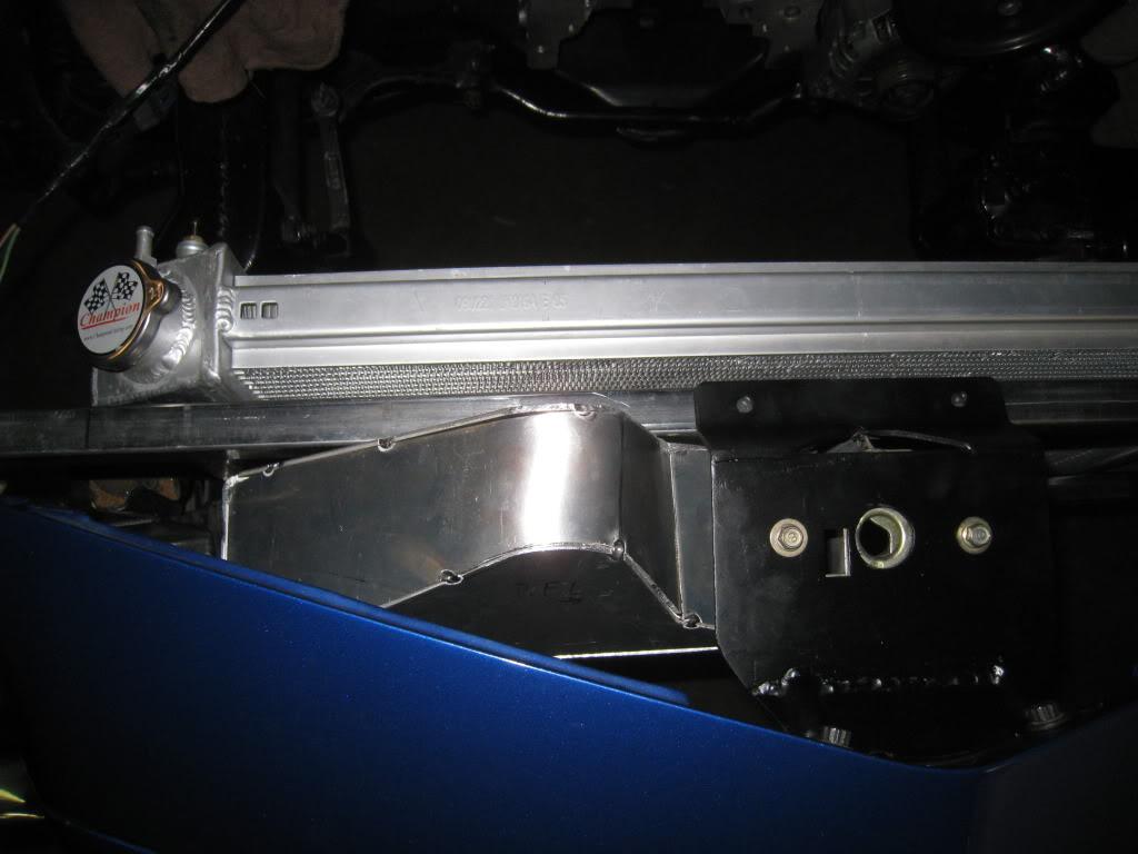
Working on the intercoolers. These are driving me nuts. How to mount, where to run pipes, clearance clearance clearance... Here's what I came up with. Hacked off the top tank and made my own, modified the bottom tank. Getting the top tank "lid" to follow the sides was a test of patience, it's not a consistent bend..

3/29/2011
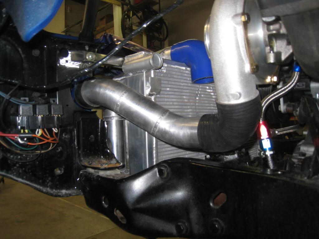
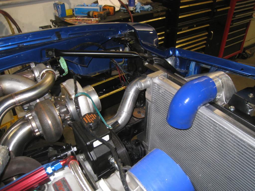
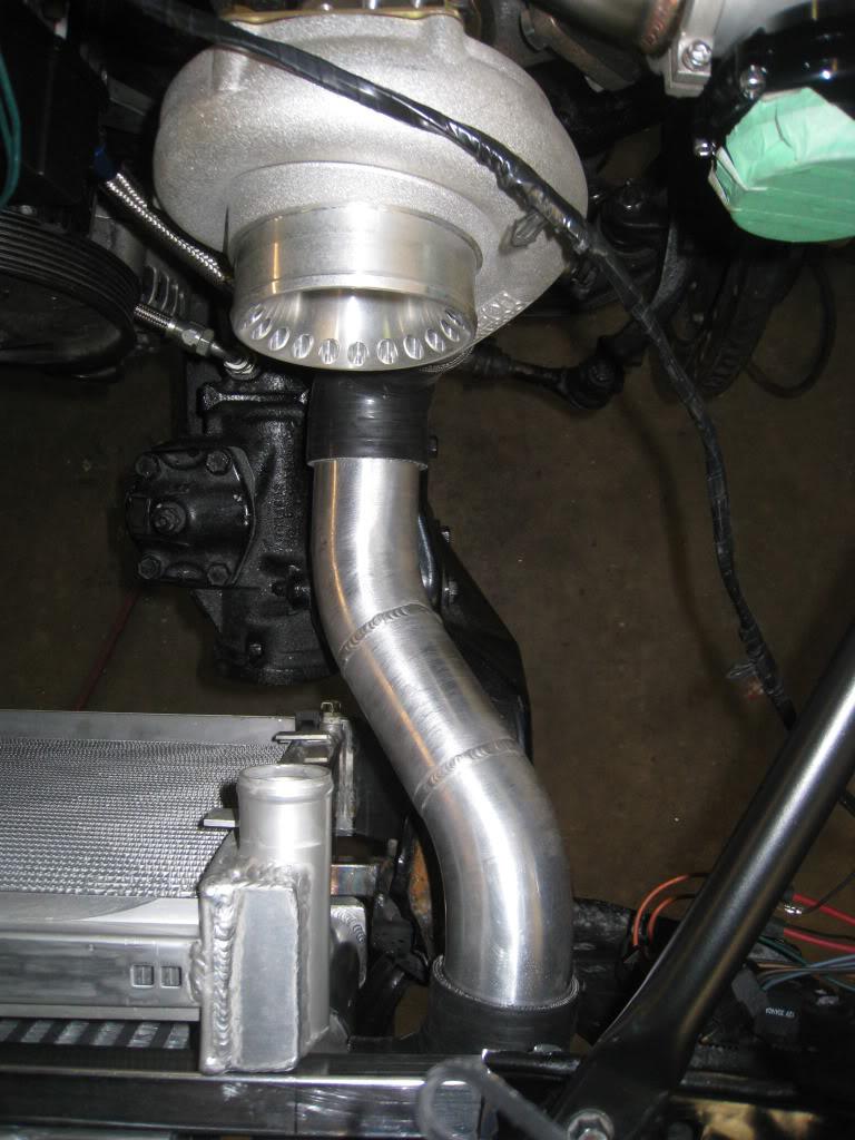
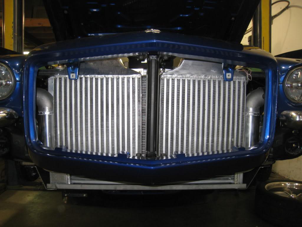
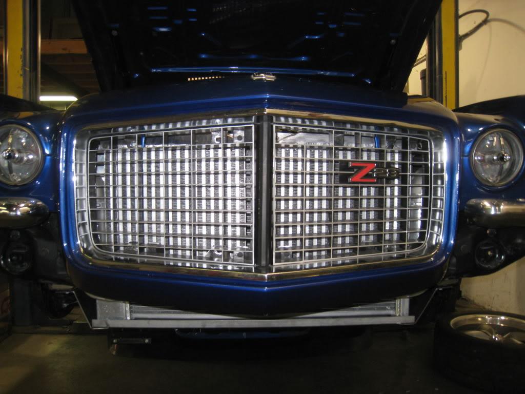
A bit more progress. Pretty happy with the layout, check out the "C notches" under the intercooler pipes on top of the radiator and rad support. The bottom 2 pics were before the notches and the intercoolers were not aligned. The blue silicone elbow was just holding the rad in place. There will be a Y pipe between there and the throttle body.
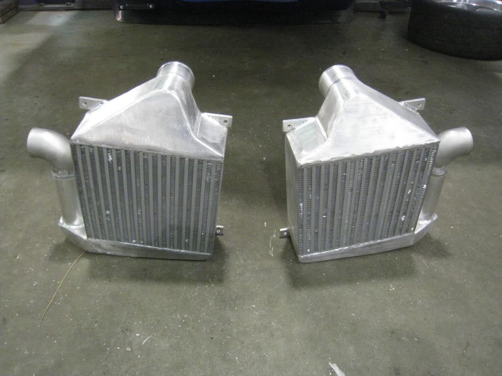
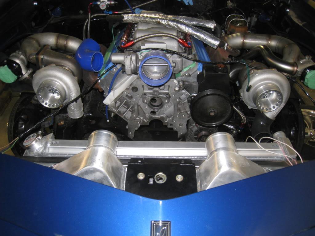
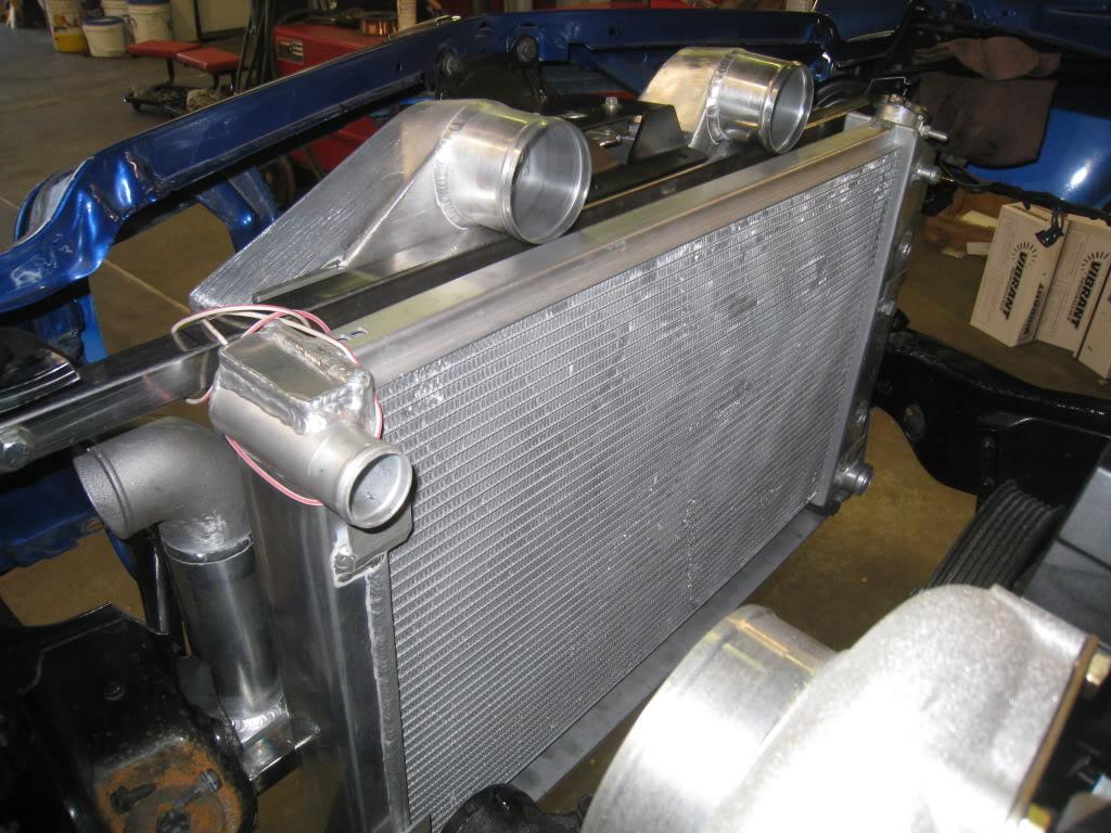
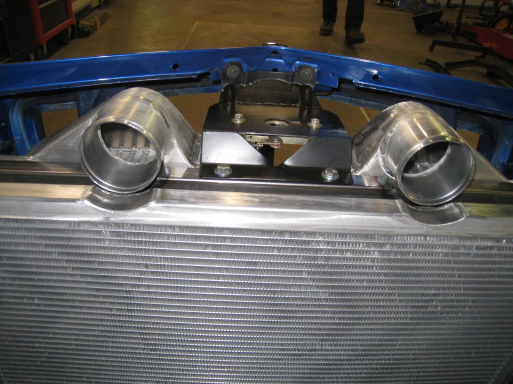
3/31/2011
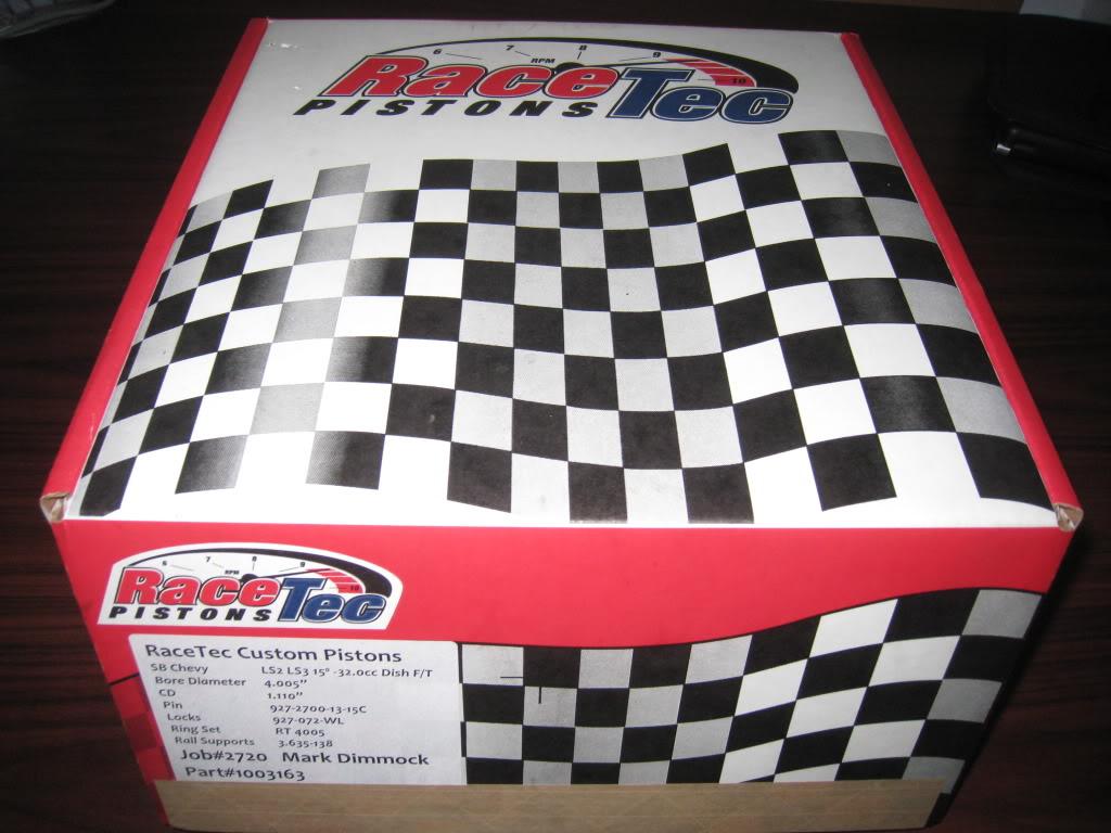
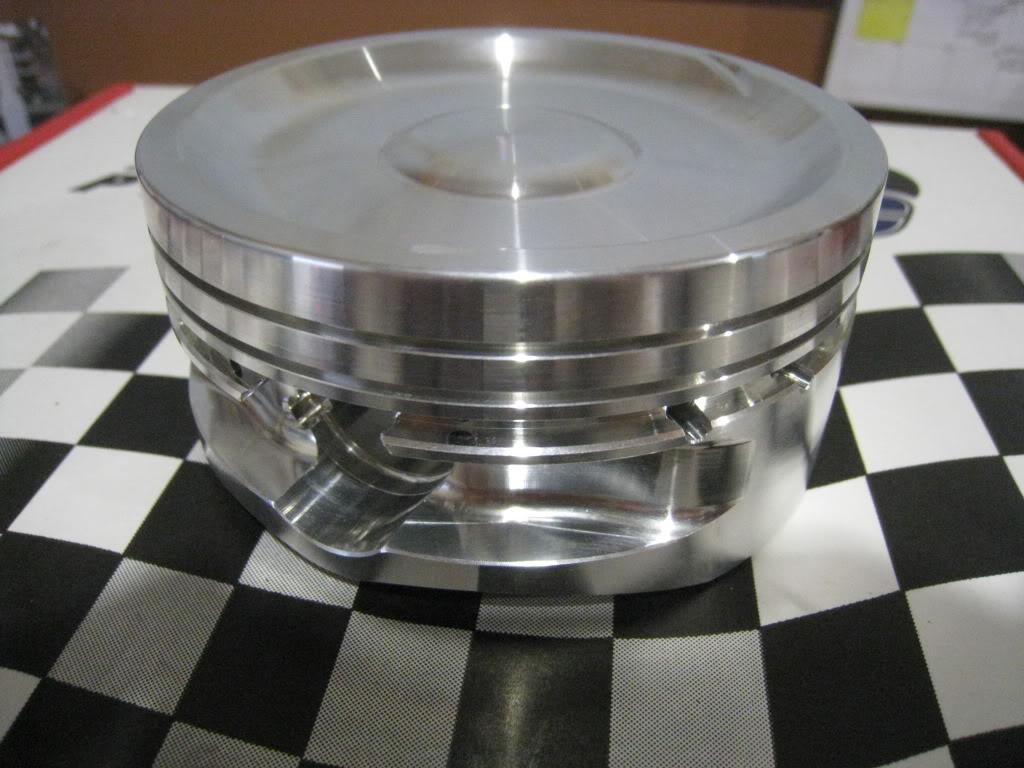
I got something special.... Big thanks goes out to Mike Callahan at RaceTec pistons. This guy knows his stuff and knows customer service! He went to great lengths to ensure that I got exactly what I needed and followed through on every aspect of the transaction. The pistons are so nice to look at it's a shame they get hidden away. Thanks for going the distance Mike, others failed, but not you.

4/9/2011
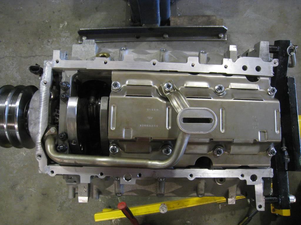
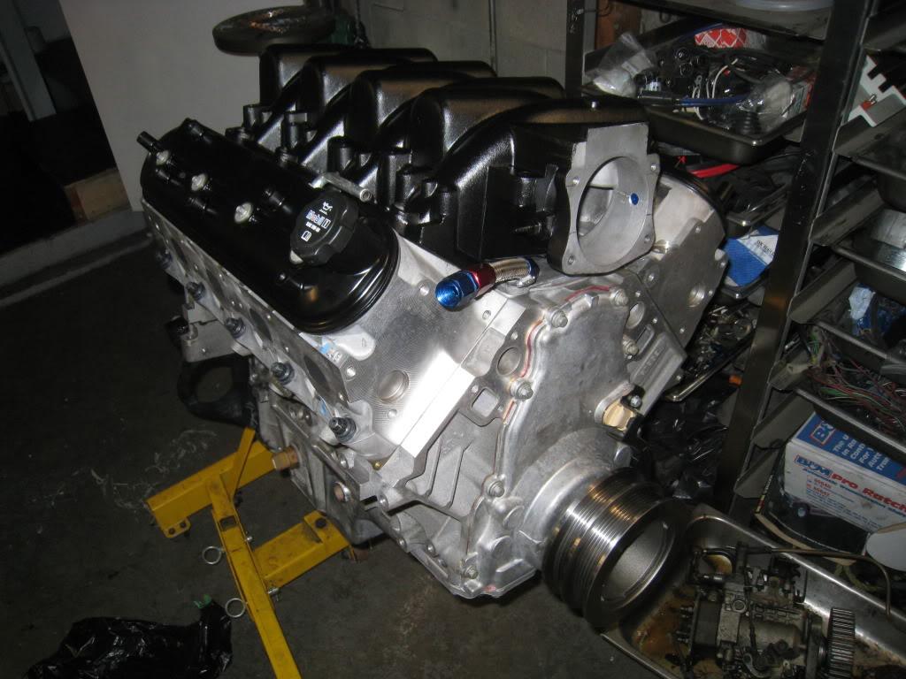
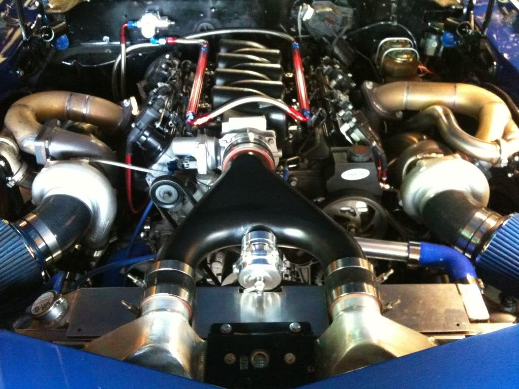
Engine is going together. Should have it back in the car in a few days, then on to plumbing oil feeds and drains, and some more pipe fab...decided to go the bare aluminum and black route this round...

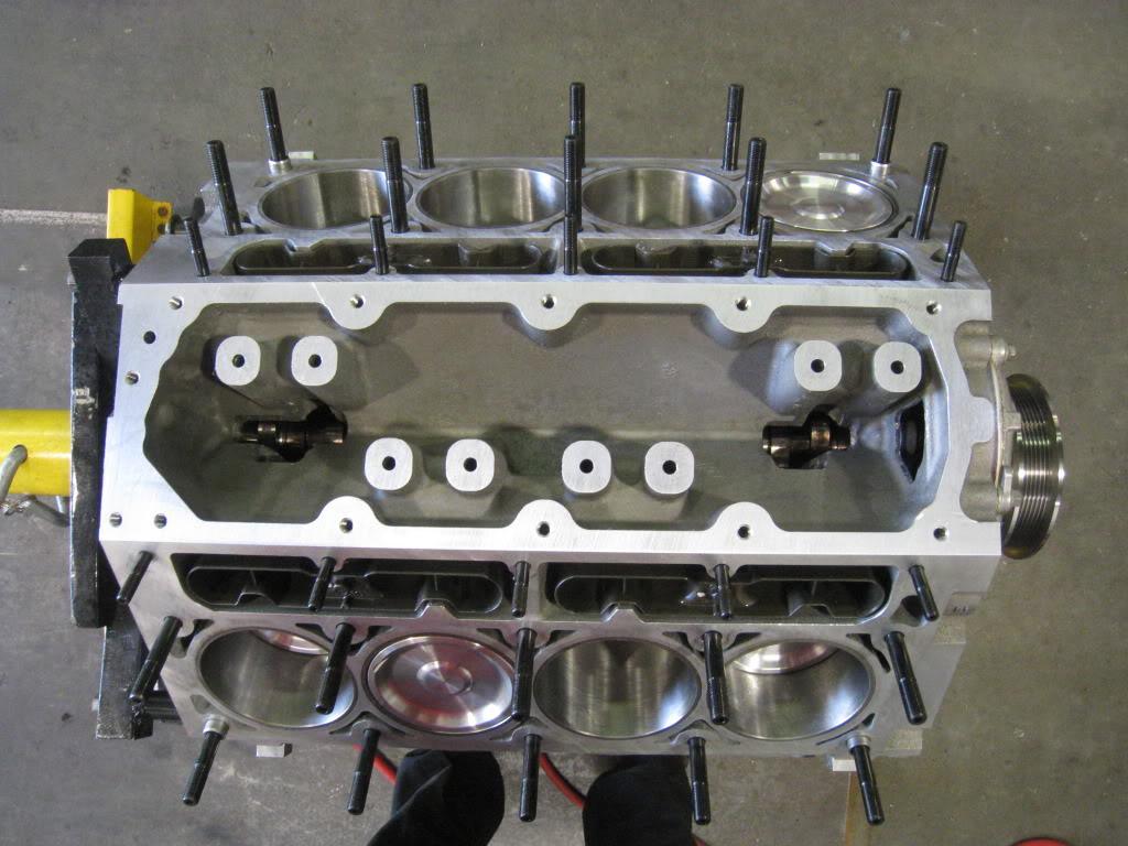
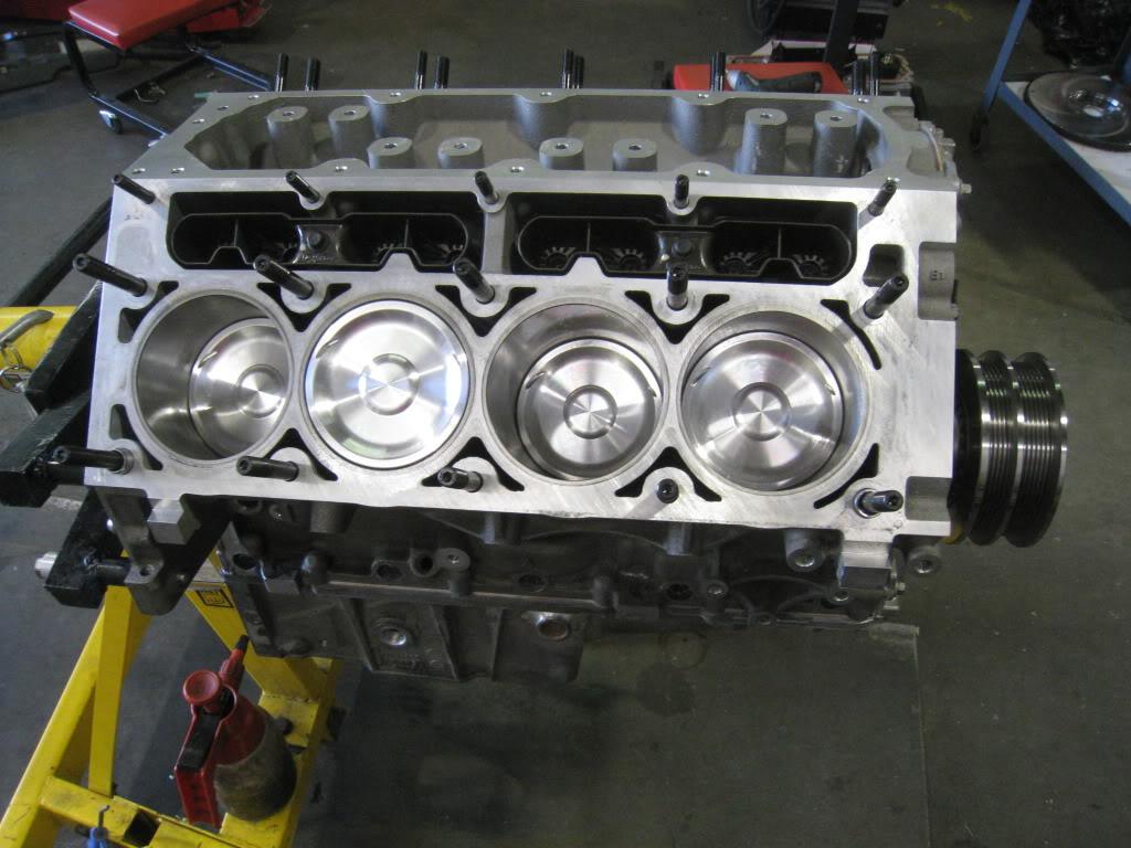
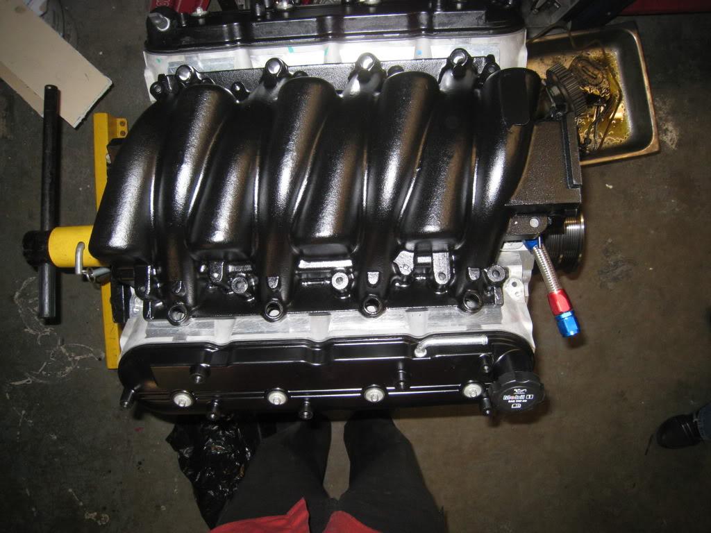
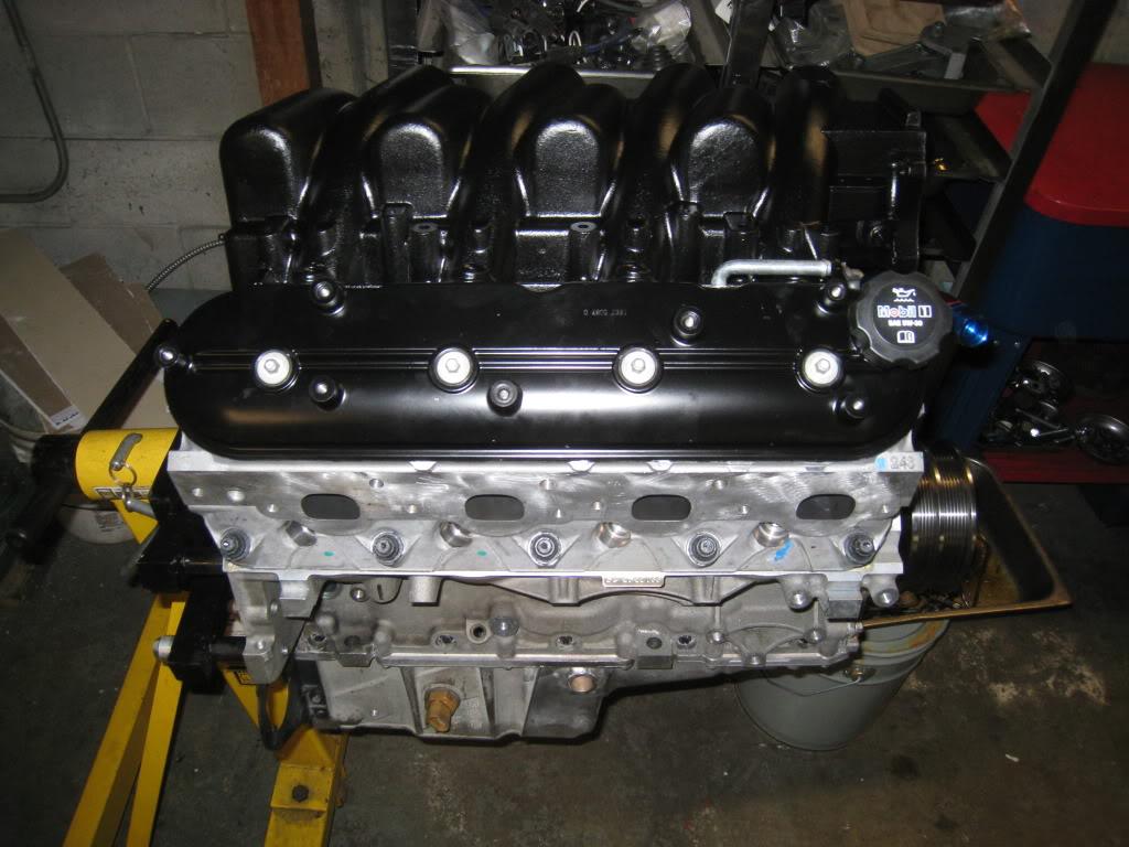
4/21/2011
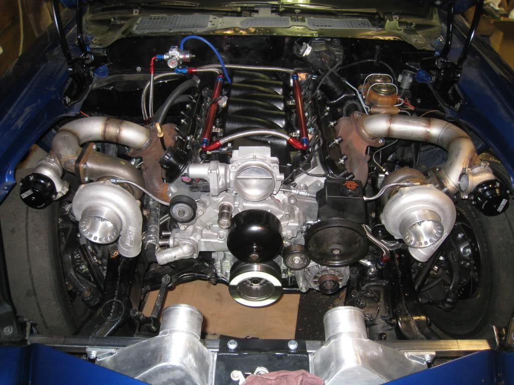
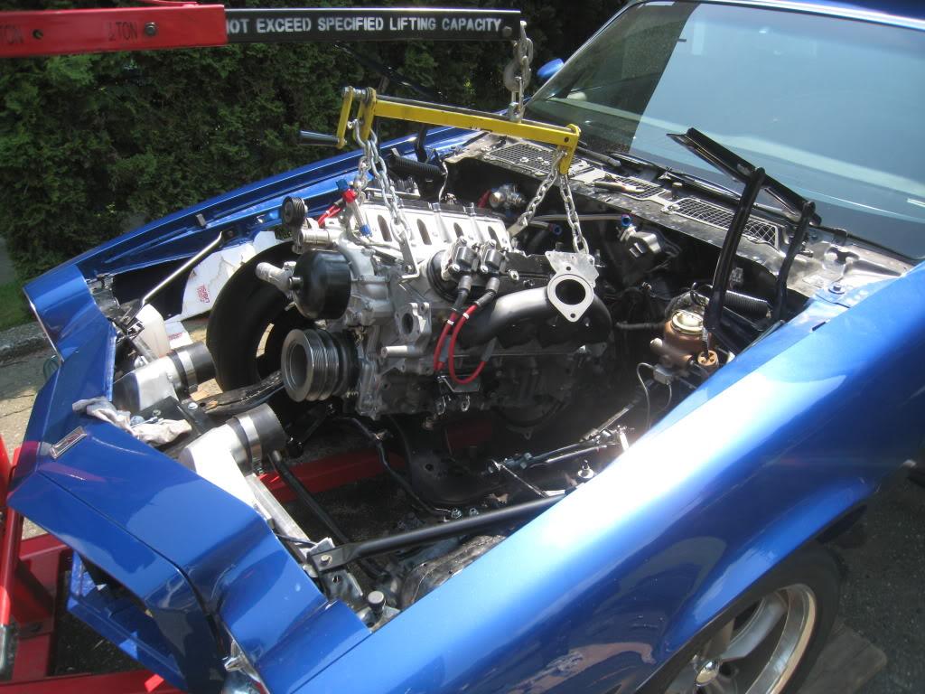
So the new motor is in. I got the Turbo oil drains and feeds hooked up, all the sensors are in, spark plugs are in, water pump installed, dipstick, alternator installed and wired, starter in and wired. I put in my 52pound injectors and am going to fire it up on my old supercharger tune. I need to do 500 miles to break in the clutch before I can dyno it anyway, and I figured that will give the motor some time to break in as well. I still have to mount my coils but have a pretty decent idea in mind. Need to spend some time working some more aluminum there. Hope to fire it up by the weekend even though I won't have the top intercooler pipe done yet. Gotta hear it run!
4/22/2011
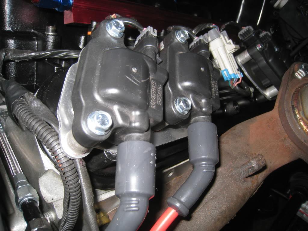
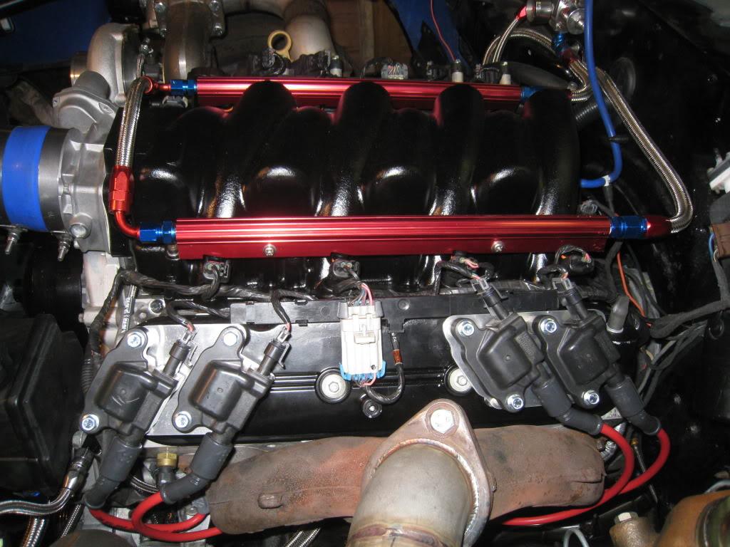
Spent a good chunk of my day making brackets to hold my iginition coils. I'm so lucky to have access to a shop that has metalworking equipment. The notcher is one of my favorite tools right now. I still do a lot of hand filing though, as that is somehow really rewarding to me. It's as close to being an artist as I get. Can't draw to save my life, but give me a chunk of aluminum, the notcher, and a file, and I'll make something purdy!
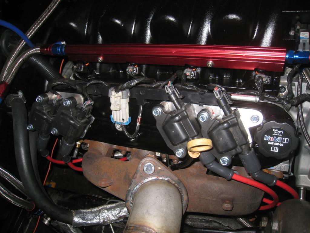


4/24/2011
A bit more work, gotta get rid of the blue and red stuff though!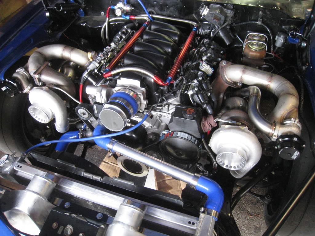
5/1/2011
I got it fired up with the exhaust on, no exhaust gaskets though, and ended up hearing a weird knocking sound. I've researched the heck out of it, some say it's lifter noise. I'm not sure so out it comes again for inspection. Better safe than sorry...
5/3/2011
Tore it all down and inspected. As suggested it was all fine. Seems to be the dreaded piston slap. I guess there are pistons available with an offset piston pin to reduce the slap. I wish I'd known about the offset pin before hand. Oh well... Should have it all re-assembled and running on the weekend.
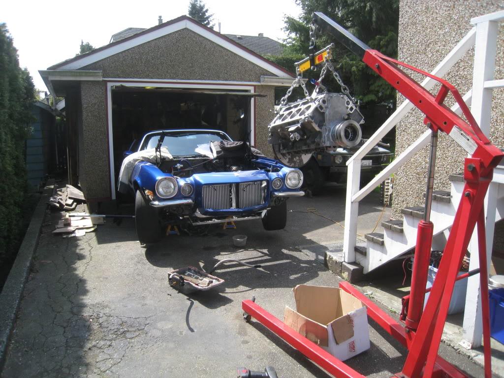
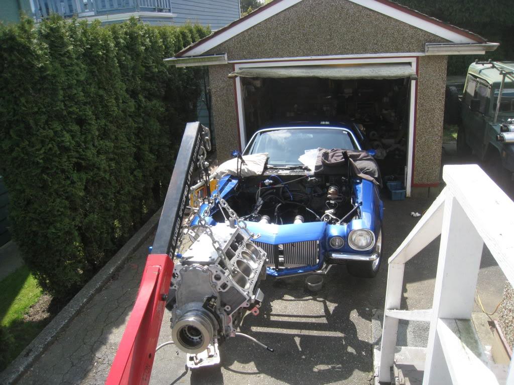
5/31/2011
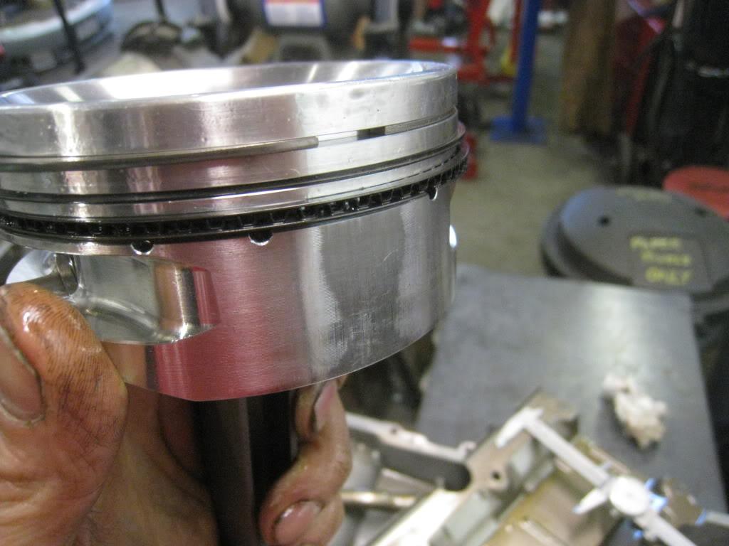
A quick update, Well, after tearing it down I found excessive scuffing on the piston sides, both major and minor thrust sides. I took a bunch of pics and relayed them to the piston manufacturer. he had me send them back to him for inspection. He sent them out to an independent measuring company, who measures to within a millionth of an inch. Turns out the pistons are ok but the problem was that the oil ring support ring that I received was the wrong size. From what I was told , once it was installed into the oil ring groove, being that it was for a slightly smaller diameter piston, it deformed into a wavy shape which in turn pinched the oil control ring which in turn prevented proper piston skirt / side lubrication. I have since received the pistons back, with new rings, and new support rings.
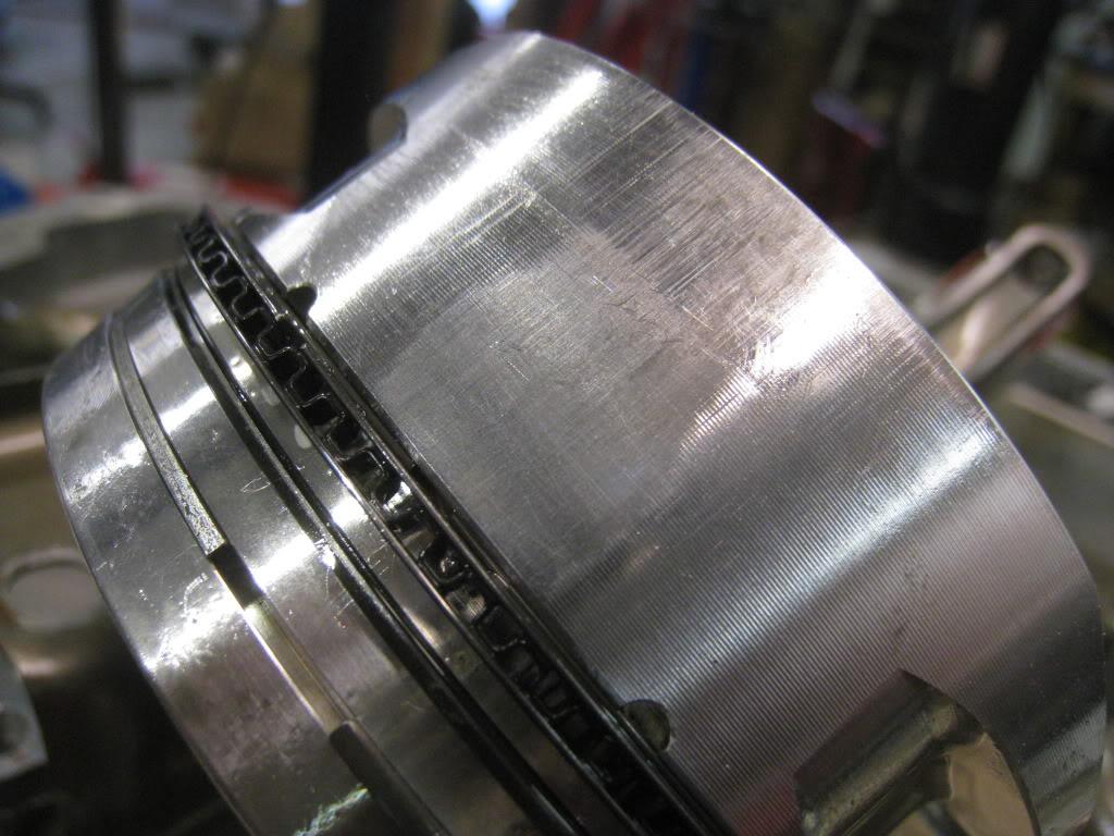
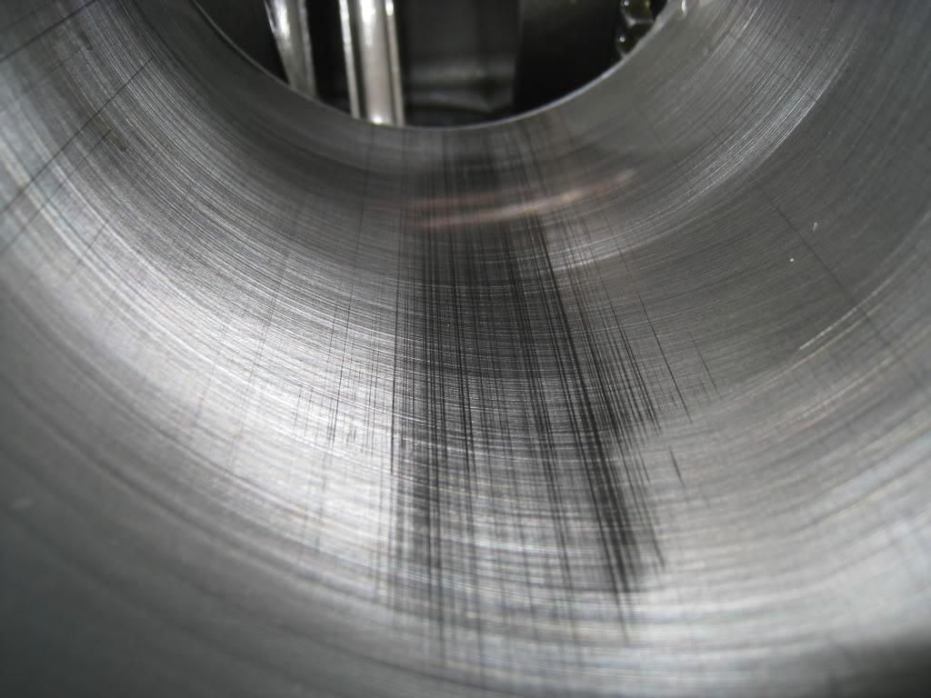
I'm getting pretty good at filing rings, as this is the third set for this engine, which still hasn't been driven.
I got everything put back together this last weekend and was lowering the car down off of the jackstands to fire it up when a wheel fell off of my jack causing the jack to stop moving and the car moved on the jack which ended up with the jack going through the oil pan. AWESOME!
I pulled the motor back out the next day, and tried to weld up the cracks but as the pan cooled the welds cracked. I ordered another oil pan and am waiting for that now.
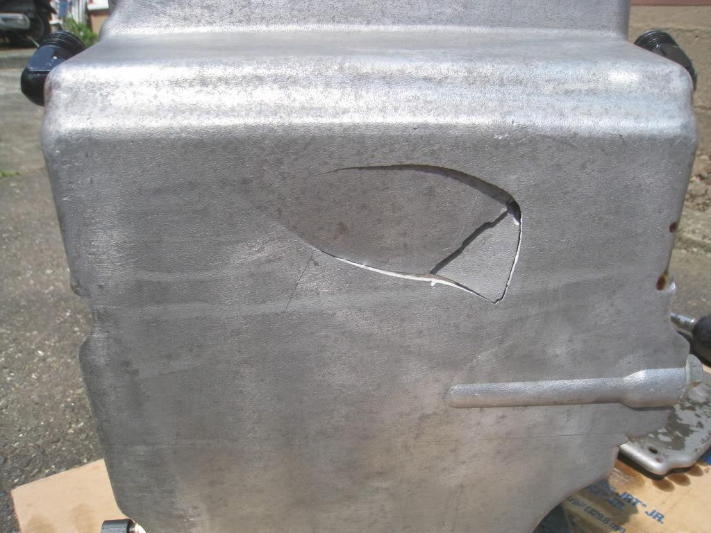
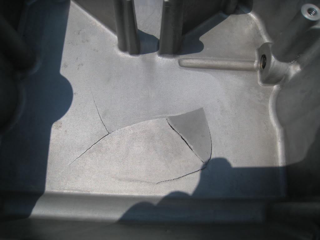
My patience is being severely tested, and I'm close to locking up the garage and breaking off the key in the locks. My birthday is a week from today, I hope to have it driving by then.
6/17/2011
All back in and running. Still sounds like a DURAMAX. I've given up on the noise and am accepting it as NORMAL. (if I win the lottery I will build a new motor, again.)
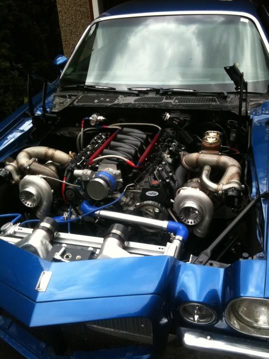
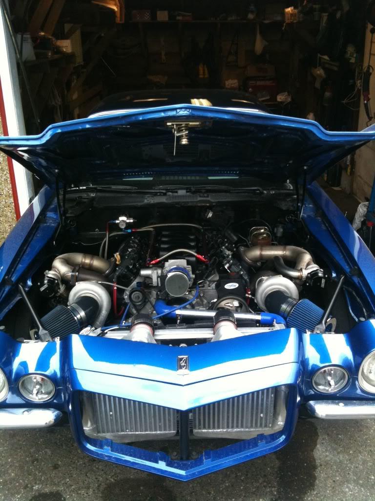
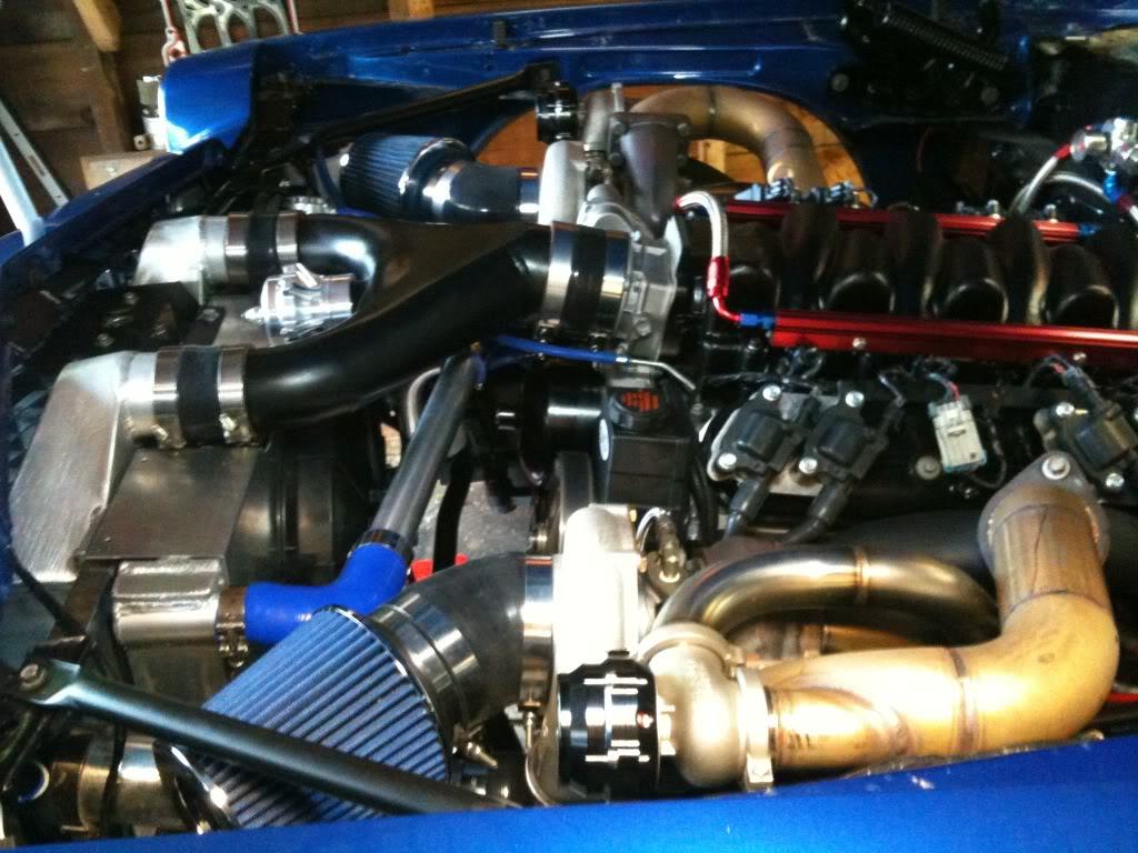
Here's some pics...note the koolcoat on the exhaust manifolds...going to wrap the turbo's and the pipes to the manifolds...
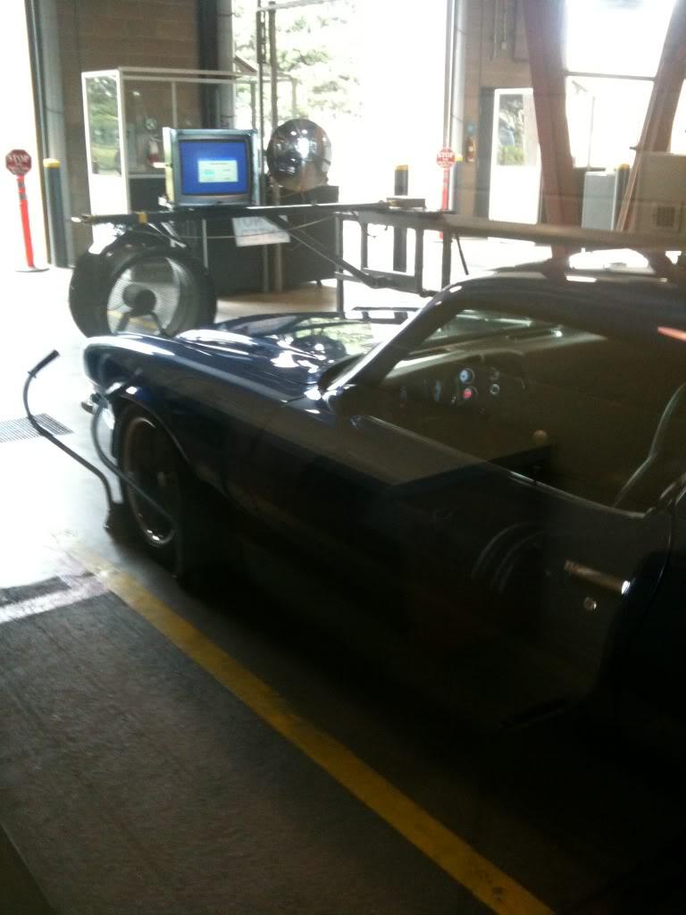
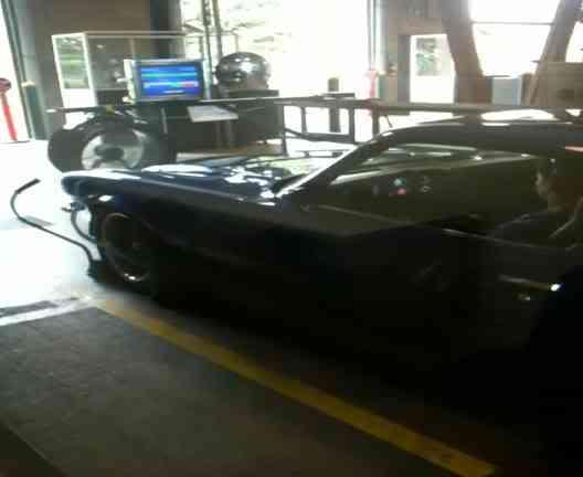
here's the car at aircare...(smog testing)...secret to pass? no charge pipes, stock tune, small injectors, testing for 1971 standards...result? CRAZY LOW NUMBERS = PASS 
The one below is a video
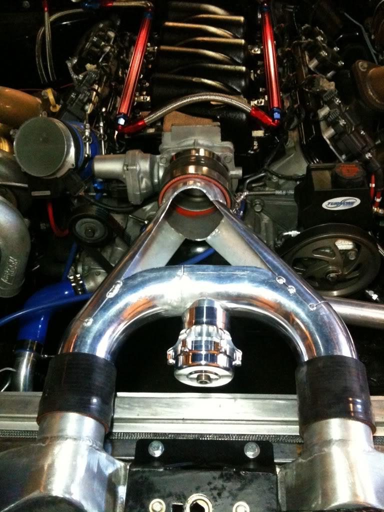
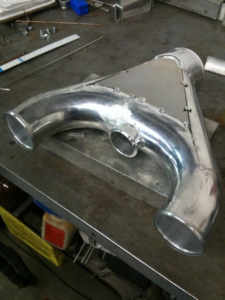
Here's the last piece of the plumbing puzzle...top merge pipe from intercoolers to manifold.
6/23/2011
Thanks guys!
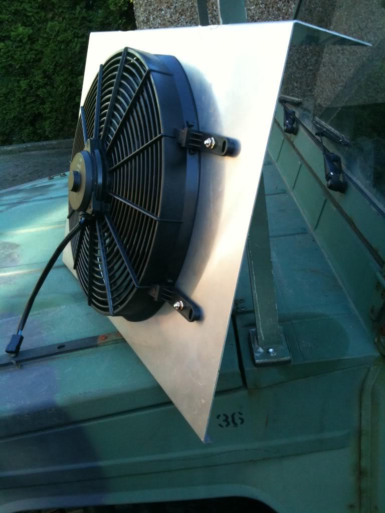
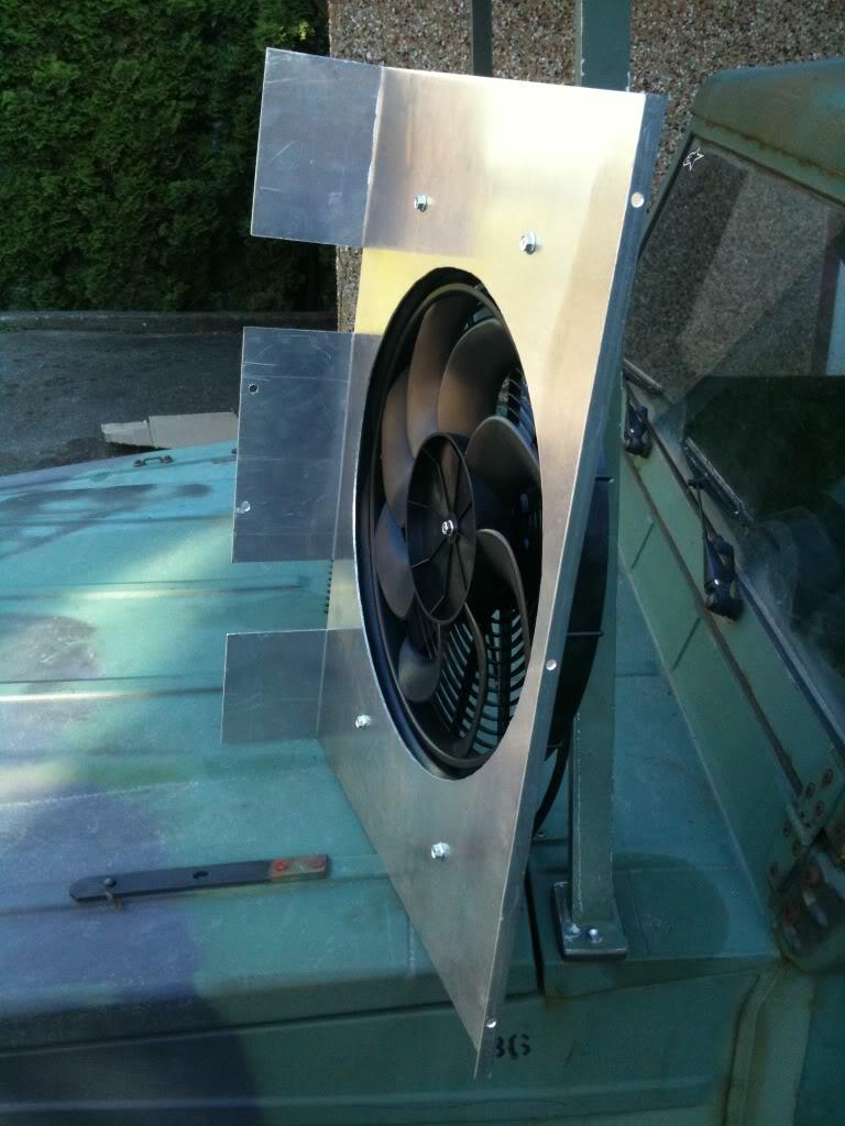
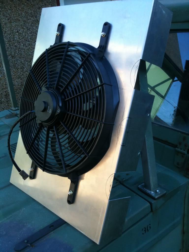
A bit more done tonight, I made a new fan shroud out of aluminum. Pretty straight forward, had to do a few notches for plumbing and the BOV.
Installed the intake merge pipe and BOV properly for the first time. Fits good. I painted it black but may go back to brushed finish.
6/26/2011
Working on the tuning now, spent 3 hours creating a 2.5 bar VE table this morning. Running now.
7/19/2011
Increased the boost from 6 pounds to 9 pounds. I don't think I'm gonna need to go to 21 psi. 9 psi, 3rd gear, 2500rpm, mash the gas, you are in the seat hard, front end is getting light, left front corner is twisting up, tires are scrambling for traction... I think my goal of breaking the tires loose at highway speed is going to come sooner than later...
7/25/2011
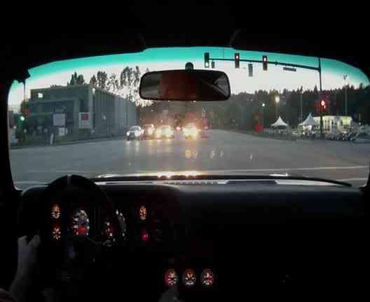
OK, you asked for it... Told my wife we were going out to get some ice cream after dinner... Funny, I could have sworn there was an ice cream shop somewhere in this industrial park ?!?? 
8/17/2011
DYNO NUMBERS...
Mustang Dyno, 15 psi boost, pump gas (chevron 94), very conservative A/R and Timing for road racing.....
622 RWHP 630 RWLBFT torque.
I ran out of time and money on the dyno to go any further. The tuner figured that on any other dyno it would be in the 700's. We had to spray the tires at one point because the power hit so hard it was breaking the tires loose.
In a couple of weeks I hope to return and turn the boost up a bit more. On a side note, with 1 degree more of ignition advance I was seeing 10 extra HP, but it would have an occasional knock. The curve was insane, full torque by 4200rpm, and it felt like there was a second torque curve from there to redline. (my tuners words)
8/23/2011
Video from the road course.
It's only 1 lap, not a fast lap, but cool anyway. The speedometer is in MPH, at 12 o'clock is 80mph and the fastest it reads in this lap (at the end on the front straight) is 120mph.
I was driving cautiously as it was a kind of shakedown day for the car. The Saleen guy came up to me in the pits later, looked under the hood, then looked at me and said "Oh..." (that explains it). His car 'was' the fast car there...
http://contour.com/stories/mission-r...x&height=540px
9/25/2011
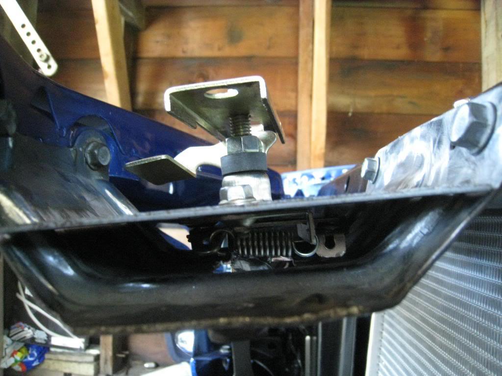
A member was asking me about my hood latch...
Hood latch mod.
It's from pre-turbo, but I think you get the idea. I got the latch from a hot rod supply shop.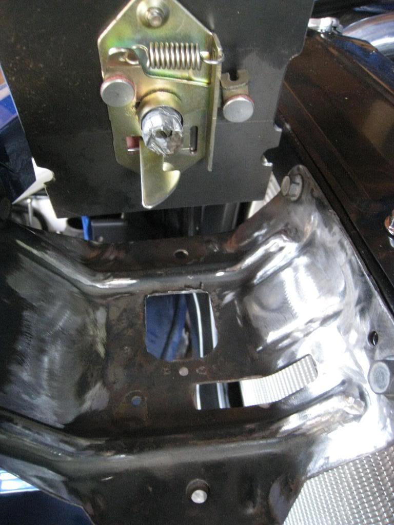



6/27/2012
These are the parameters I used to get my fans to work with my E38 ecm.
Operating system 12614676. From the 2 fan outputs from the ecm, using standard relays, on/off on each fan. (we'll call them the low temp fan and high temp fan)
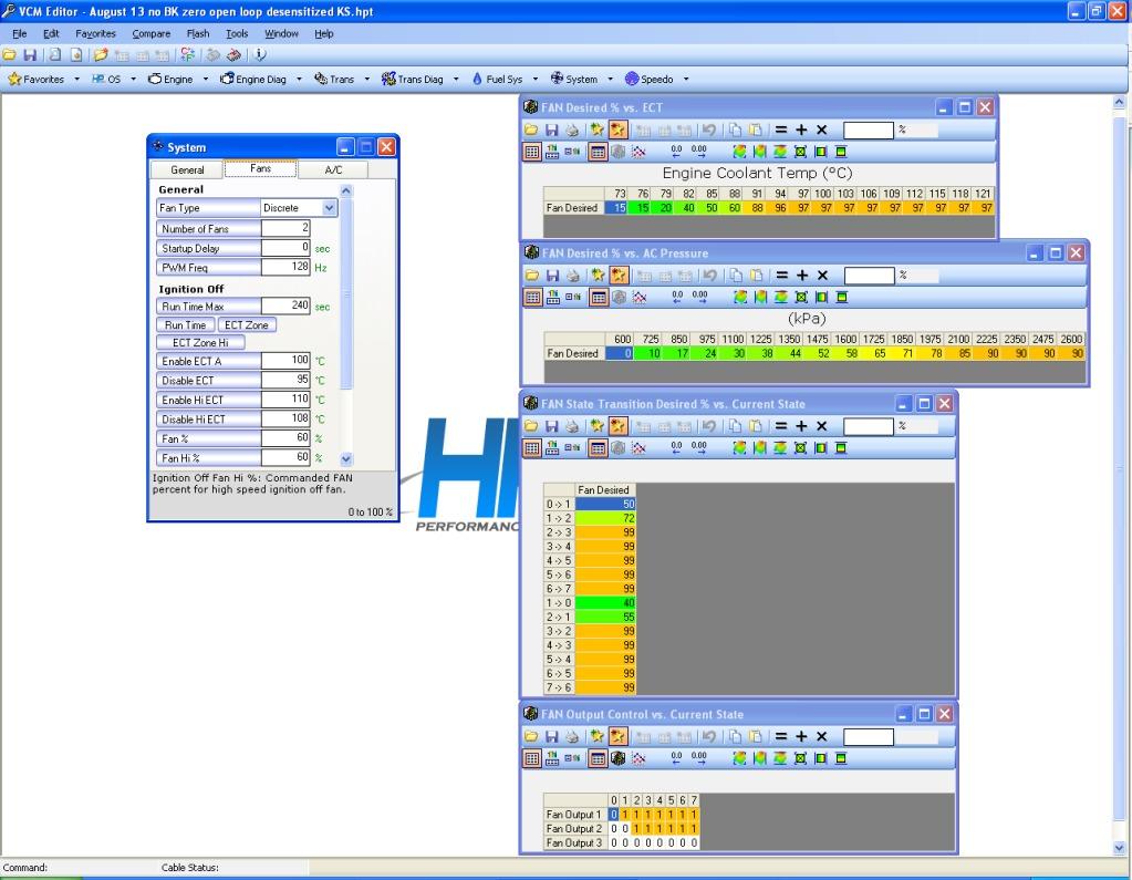
Hope this helps...
8/12/2012
Well, if my tires arrive in time, and fit, then August 17th, 2012 I will be running my car down the 1/4 mile. I ordered a pair of 285/40-18 Nitto NT05r drag radials for it. I've never tried to launch my car before so it should be interesting. I'm thinking I may try starting out in 2nd gear as 1st gear is really low and I don't imagine I'll get much traction. Any tips or suggestions out there? Anyone want to guess my et? Mission raceway friday night street legals. Should get there around 6pm.
8/18/2012
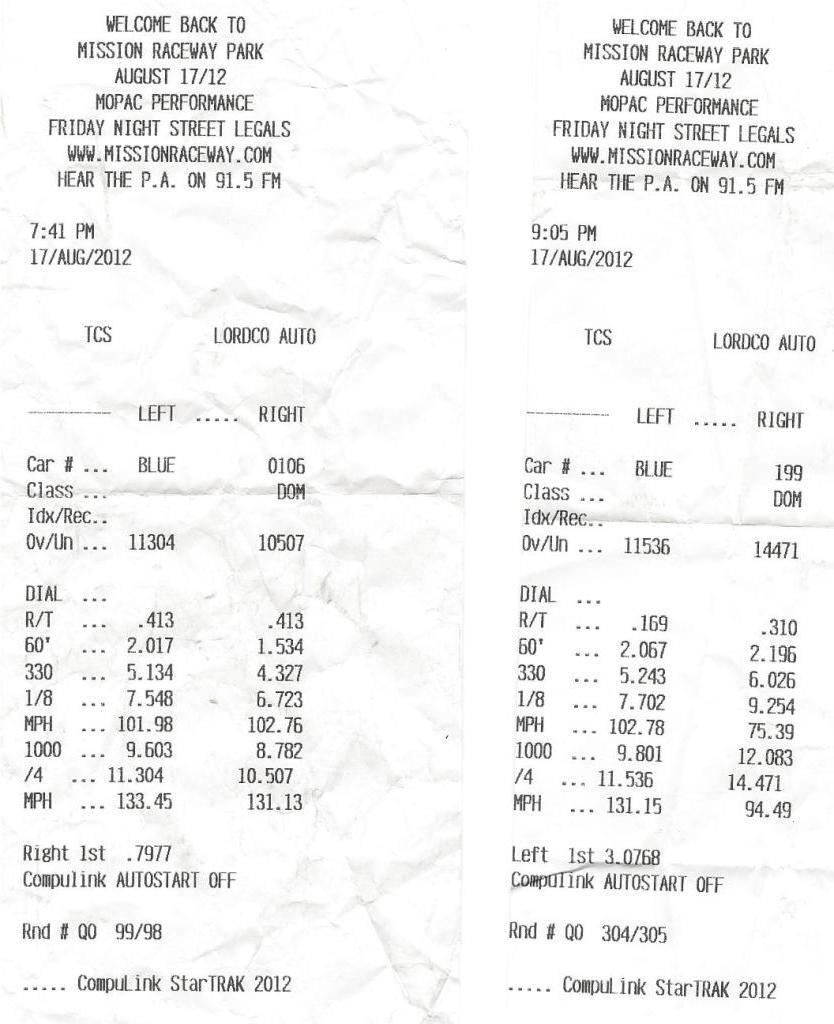
August 17th. Mission Drags Race 1. Everyone always asks me "what does it do in the 1/4?" Now I know. 11.304 @ 133.45mph. I've never drag raced the car before or even done a burnout. (not from a standing start anyway) I've always rolled out slow then got on the gas in higher gears as the tires always break lose anyway. So my burnout was a total fail. For the record the teperature at the track was around 30c (86f) and the humidity was very high. My tires were brand new Nitto NT05r's at 18 psi (285/40-18) running 15 psi boost.
I got some last minute coaching from another driver while in pre-grid ( thanks Ivan in the Black procharged TA ) and was super nervous. It was fun though and although my transmission is noisier than before nothing broke and I drove it home. Sounds Like a win to me!
Here's the on board video... so embarrassing...
http://contour.com/stories/august-17...n-drags-race-1
4/25/2013
I've been driving the Camaro pretty much every sunny day and my transmission sounds like it's going to blow up soon. Anyone reading this thread have any personal experience on T56 upgrades?
5/31/2013
It's true... I'm looking into a sequential... That MTI unit looks good but so far no pricing and it's corvette only... The quaife is do-able, over $12k though, so I need to sell some of my other toys to pay for it...
6/12/2013
It's been a while since I did any work on my car and I felt like it was time for some upgrades....soooooooo.....
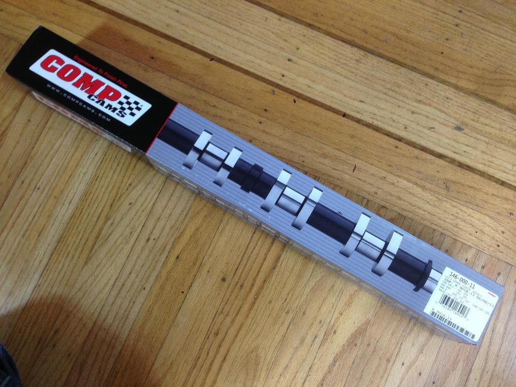
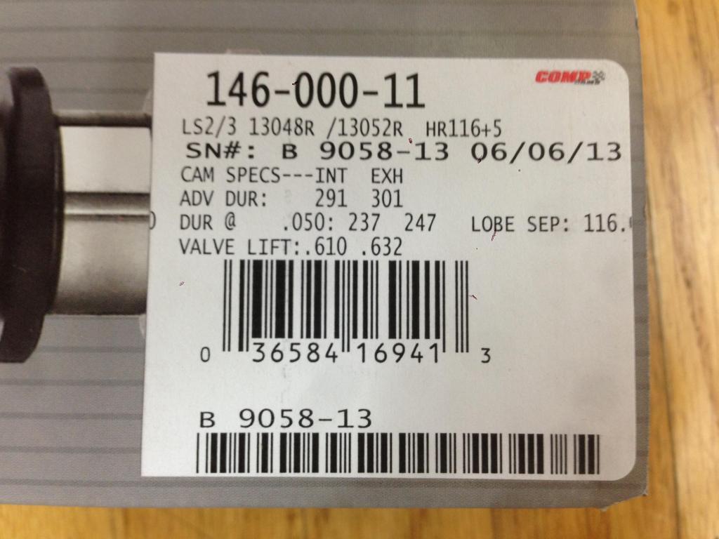
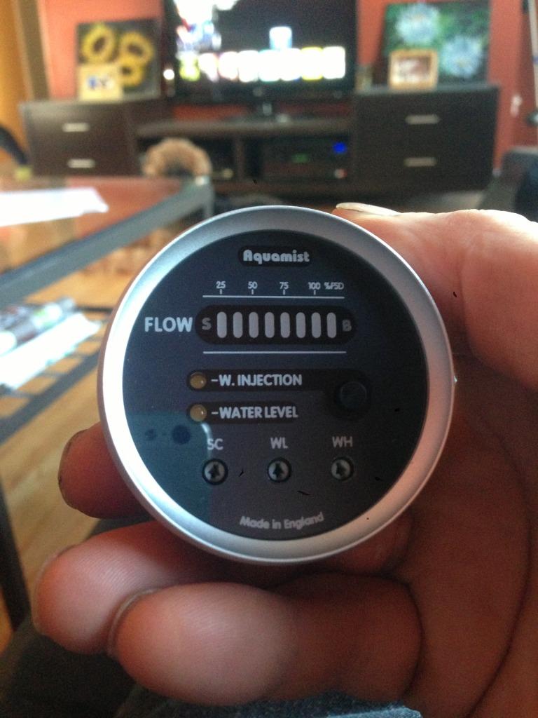
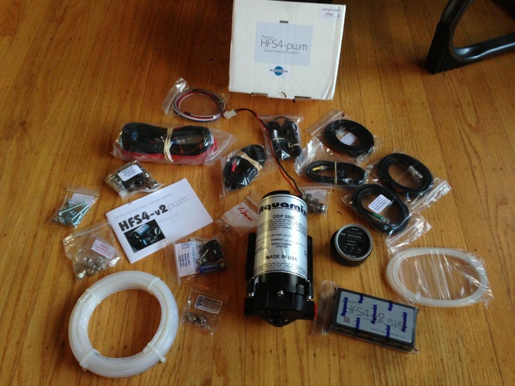
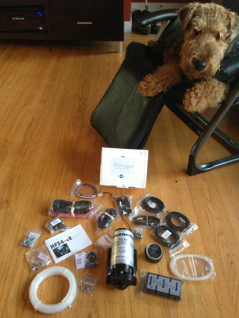
New Cam as spec'd by Martin at Tick Performance, and an Aquamist HFS4 as spec'd by me. I'm gonna go for broke and see what happens when I use all the boost I can muster!!
Spencer approved!!! (woof)
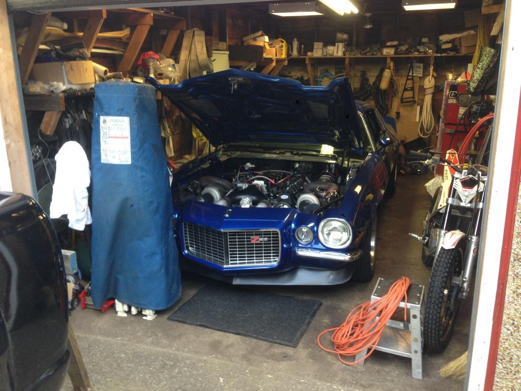
Wow! It took me over 3 hours just to clean the garage to be able to put my car back into it! Should start on the cam tomorrow night.
6/16/2013
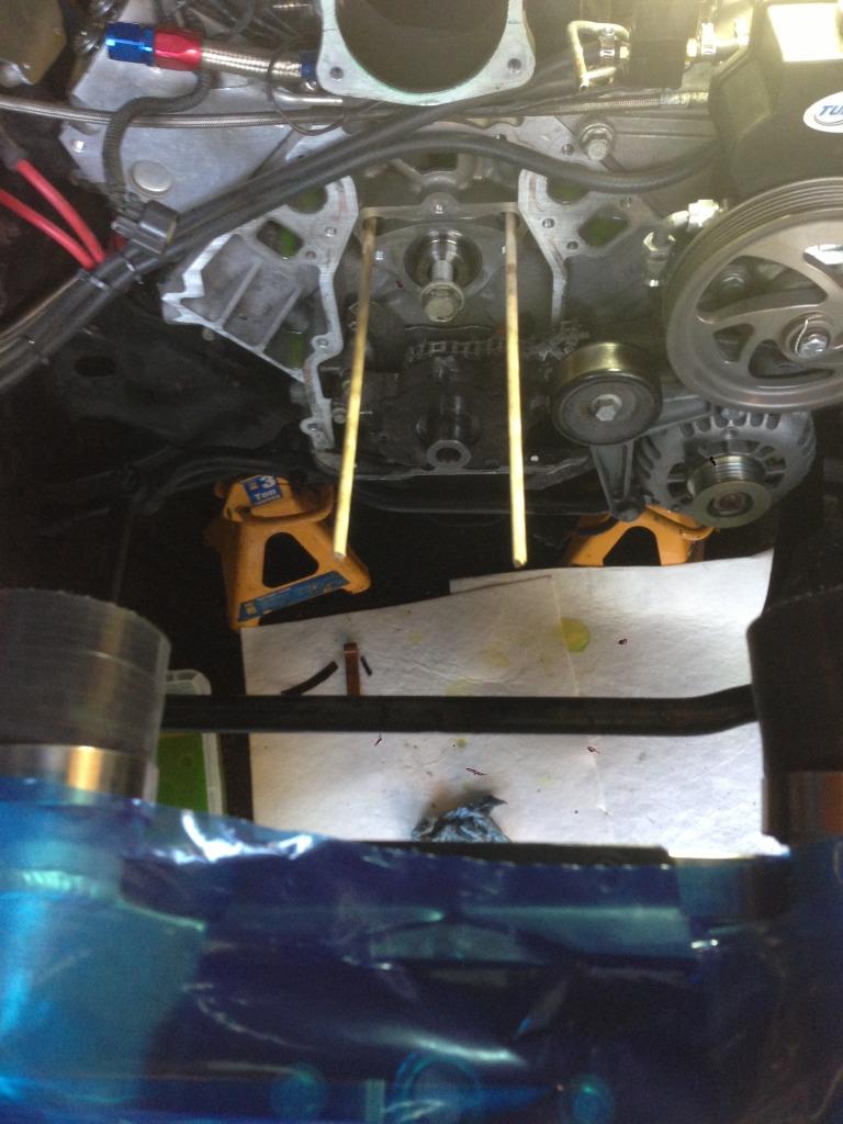
I used the 5/16 dowel trick to hold up the lifters and yes, it works!
There was just enough room to get the cam out without removing my intercoolers.
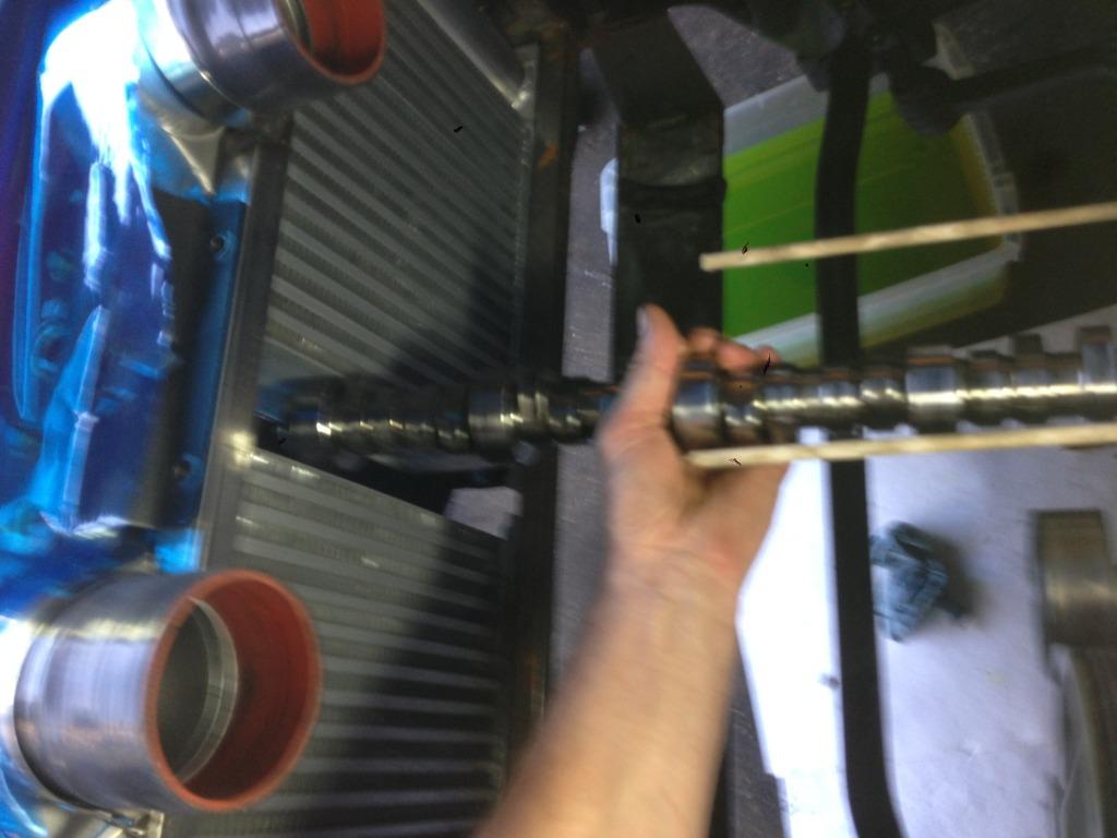
The cam is in, drove it around the block but no real test yet. The computer still needs to do some more self tuning. Sounds good though...
BEFORE...
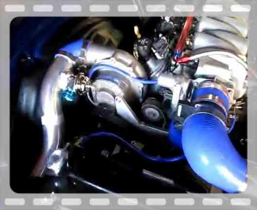
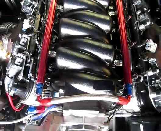
Great build!
Posted by Diggymart on 2/14/20 @ 5:54:05 PM