You must be logged in to rate content!
16 minute(s) of a 620 minute read
1-17-2012
lclark2074, the male part is angle iron. The original intention was just to shape plastic panels and sheet metal. Then I did 3/16" flats and 1/8" flats. Then I bent 1/2" rebar and kinda abused it abit. Next time I build another brake for the press, I'll have a better idea of what I'm going for.
For the rest of ya... Thanks for the compliments, I just hope some of what is being taught will be used in somebody's shop some day.
Finally I've got all the pieces fabricated and tack welded, I'm very pleased with the assembly.
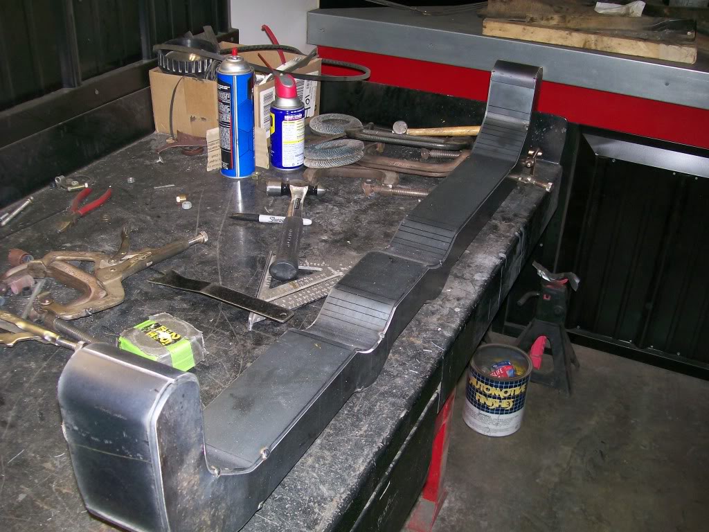
As I mentioned earlier, I cut all the tack welds and disassembled all the pieces.
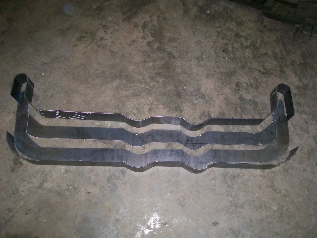
The main reason for the disassembly was to drill the mounting holes. I could have drilled these before I did all the bending and shaping, but I didn't really know what I was gonna end up with, so I went right to the bending process. Also, drilling the 3 1/4" distance from side to side was too far for my drill to reach.
On another note... I could have done 1 mounting bolt on each end. I opted to use 2 bolts per side. I figure along with supporting the transmission/transfercase, if I used 2 bolts per side, it could add a little strength to the frame at the same time. One bolt per side would act as a pivot, but two bolts per side acts as a stabilizer and keeps the frame from twisting in this mounting location.
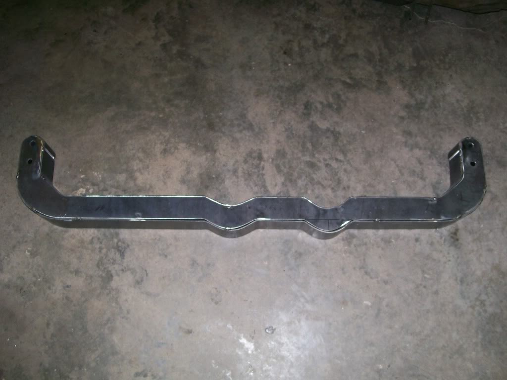
1-19-2012
Wildspear, I'm very happy with the progress. Much of what I'm doing has been on my mind for many years. It's not easy to say "ok, the truck has to come apart for a while". I still have many more items to redue, but those will be at another time.
94yjstocklook, your at a time in your life where it's an open book. Soon you'll have to make decisions to either chase childhood dreams, or make decisions stepping into adulthood. I grew into adulthood, then finally decided to go back to what made me happy when young, building and fabricating. It made my to decision to build my dream shop easier.
I've mentioned installing tubes in the area where you'll be mounting the crossmember. This idea is necessary for anything you build that is a box design. Without these tubes from side to side, the side walls could compress as you tighten the bolts. These tubes create a solid situation to tighten the bolts as you need to.
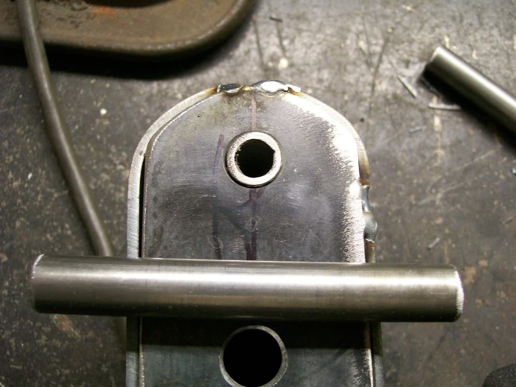
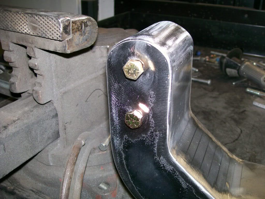
Finally I got all the welding done, I think it was nearly 18' of welding. Then came all the grinding. I think what looks the best is it looks like a solid chunk of steel. I used 4 or 5 flap discs, but they do a great job.
Here's an idea of how the bolts go and an idea of how most of the grinding turned out.
Finally I get to check the fit.
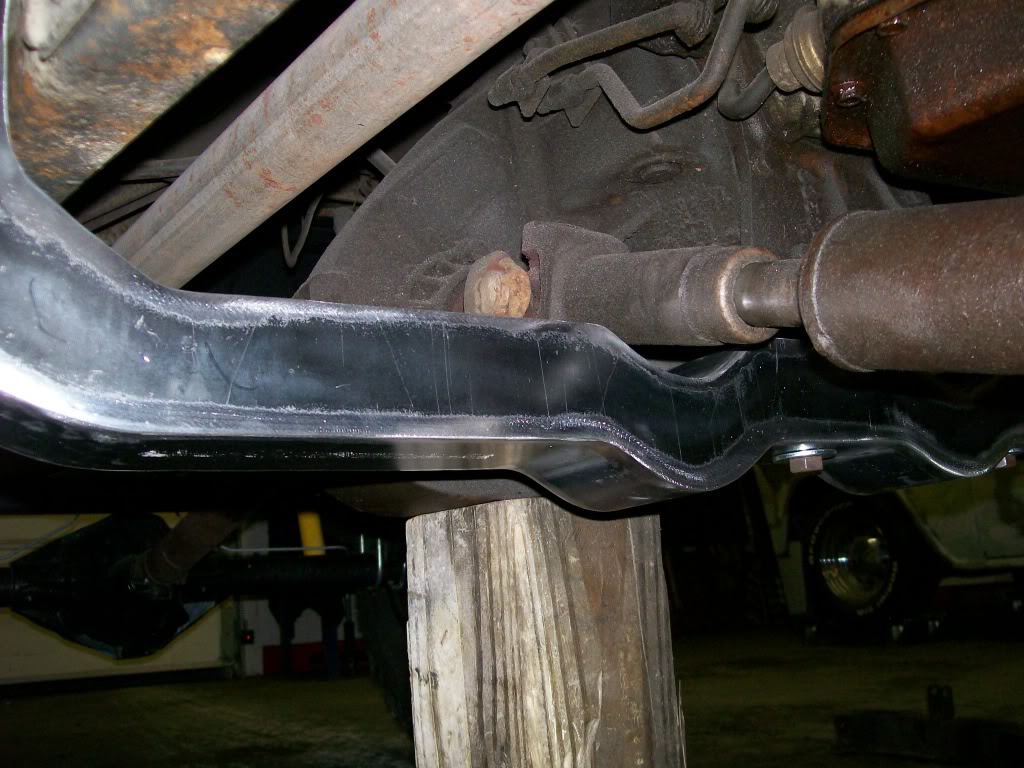
1-20-2012
Showtime3492, long time, good to see you're still out there. Slow and steady was the key to this shaping.
GotJeeps, you are very correct, I stumbled upon that brand a couple years ago, I believe they were orange in color. Yes, they were the best balanced flap discs I ever used also. The place I got them from stopped carrying them. I've tried about 4 different brands and settled on the Grizzley ones. On this crossmember, I just had a ton of grinding to do.
94yjstocklook I'm cutting the mounts tonight as a mater of fact.
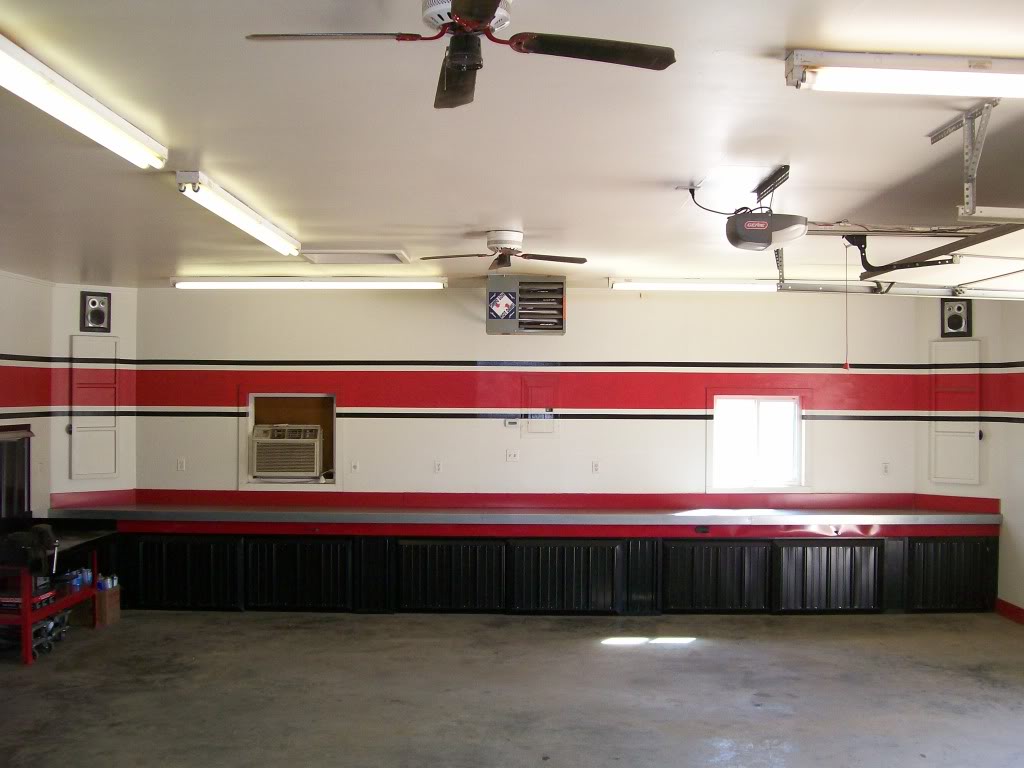
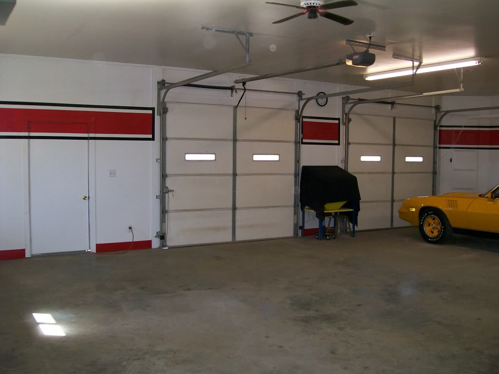
Harold_Ray, because you asked, I will show. Keep in mind we all have different priorities. As I was finishing this, people wanted me to use the roll up air hose reel that hangs on the ceiling. They wanted to see hanging cabinets. They wanted to see pegboard. Nope, it wasn't gonna happen, all that stuff does 2 things. 1) Collects dust. 2) Spiderwebs. 3) Bunch of visual clutter. Ok, 3 things.....
Bright and clean, that's what I wanted. Notice instead of cabinets, I 45 degreed the corners. That's all shelving space. No 90 degree corners, less spiderwebs. The nearly 30 feet of counter top has nearly 30 feet of space for storage underneath. The doors roll from side to side to expose storage space and also roll out shelving units. AC in the window, heater on ceiling, ceiling fans also. The work bench on the left is my main welding zone. I used the same outside metal building siding on the wall to deflect sparks as I used to make all the doors under the counter top.
Back wall, same welding bench, lathe (its old but does the job) . Press, torchmate table. The door to the right of the lathe goes to a 10' x 10' room. In this room is all the welders, torch, air compressor, couple cabinets, drill press, ect. Good storage area, yet clean, dust free, and out of sight. Most everything I could I put on wheels, I roll out what I need. The torchmate table is also on wheels.
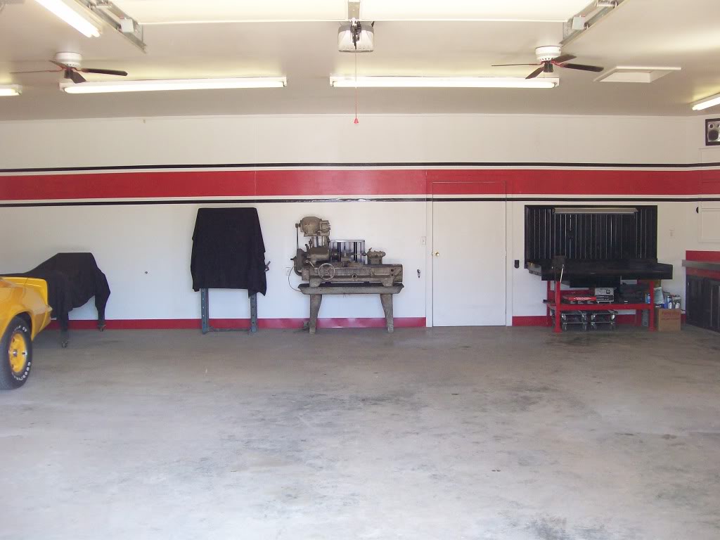
Front wall, garage doors, front door, glass bead cabinet. On the last wall, it is a straight wall, 45 degree corners. One corner is all shelved storage behind a door. The other corner is 45 degree but no storage. It does have a door. When you open the door there are 2 air filters, the cavity that the 45 degree makes actually directs air that is being pulled by an exhaust fan up and outside. The fan is not seen, nor is it barely heard, but it works great. The nice thing also is I don't have a big round hole in the wall with dirty fan blades. I run the fan, then shut it off and close the door. Everybody always thinks its another storage unit.

Thanks willysworker, I'm glad you like. Altough it was alot of work on the frame, it was a personal quest to see how well I could do to take something so rusted and repair it to a condition that no one could tell it was repaired. So far most everyone who has seen it can't tell, and at this point I'm tired of trying to convince them of the work that was done. Lol, I guess mission accomplished.
By the way, I love it when the drilling removes material as in the picture.
TSCHNEIDER, you must not be on dial-up. I am, and I tried to skim through the pages..... took forever......

It looked so good, yet I just had to hack into it. There is an angle that I just couldn't plan into the design. The Willys frame makes quite an angle as it passes under the cab. Even If I tried it into the design, I'd have problems shaping all the flats to fit. After a test fit and measurments, I put the metal cutting disc into the 4 1/2" grinder and removed a chunk.
In this pic I've made the cut and ready to shape a new piece into the opening.
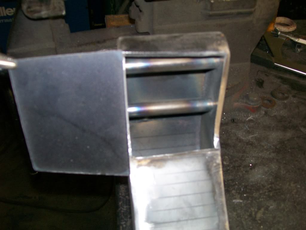
With this next pic you can imagine how this crossmember will fit the angle of the frame now.
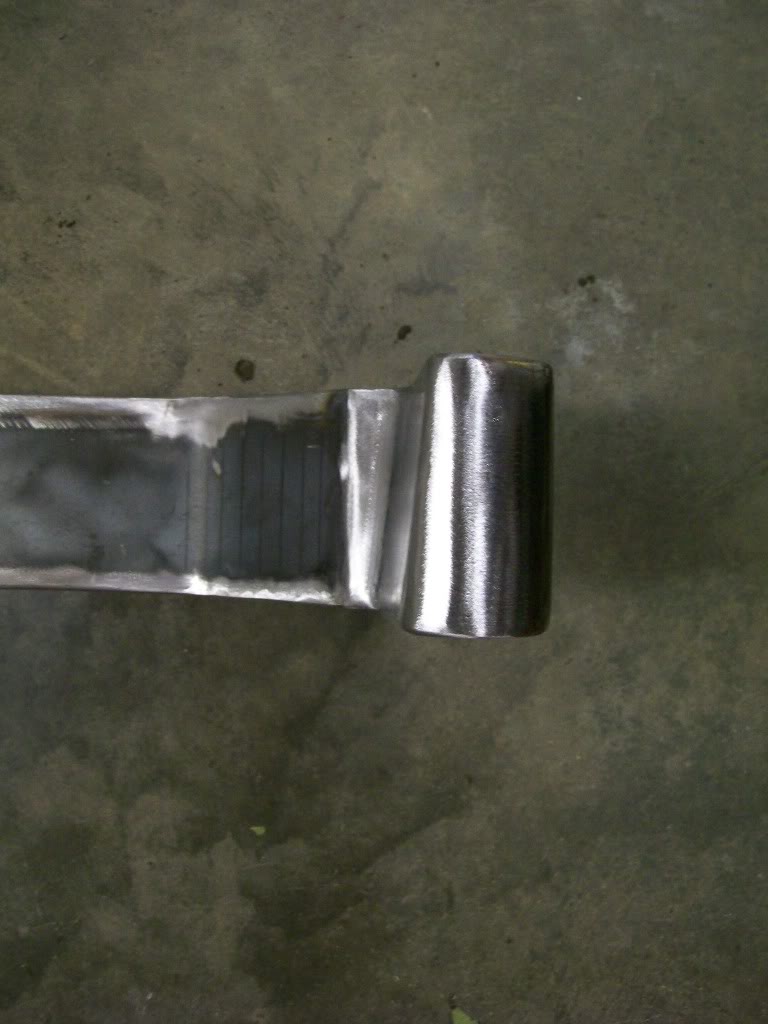
Both sides are done now. With the crossmember fitted to the frame, I have now started cutting the bracket that will attach it to the frame. Should have pics of it in the next day or two.
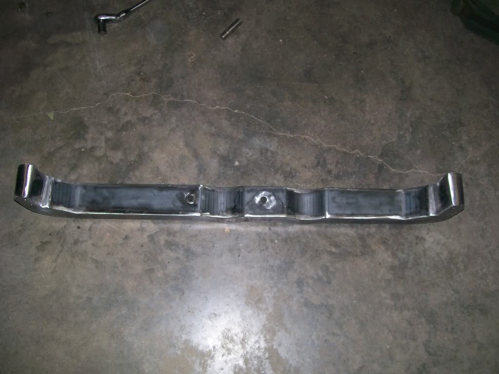
1-22-2012
Dial-up, aaarrgh. Since the Flintstones were a modern stone age family, do you suppose they used dial-up?

Since I forgot to take a picture of the individual pieces before I started assembly, the best I could do it take a picture of where they came from.
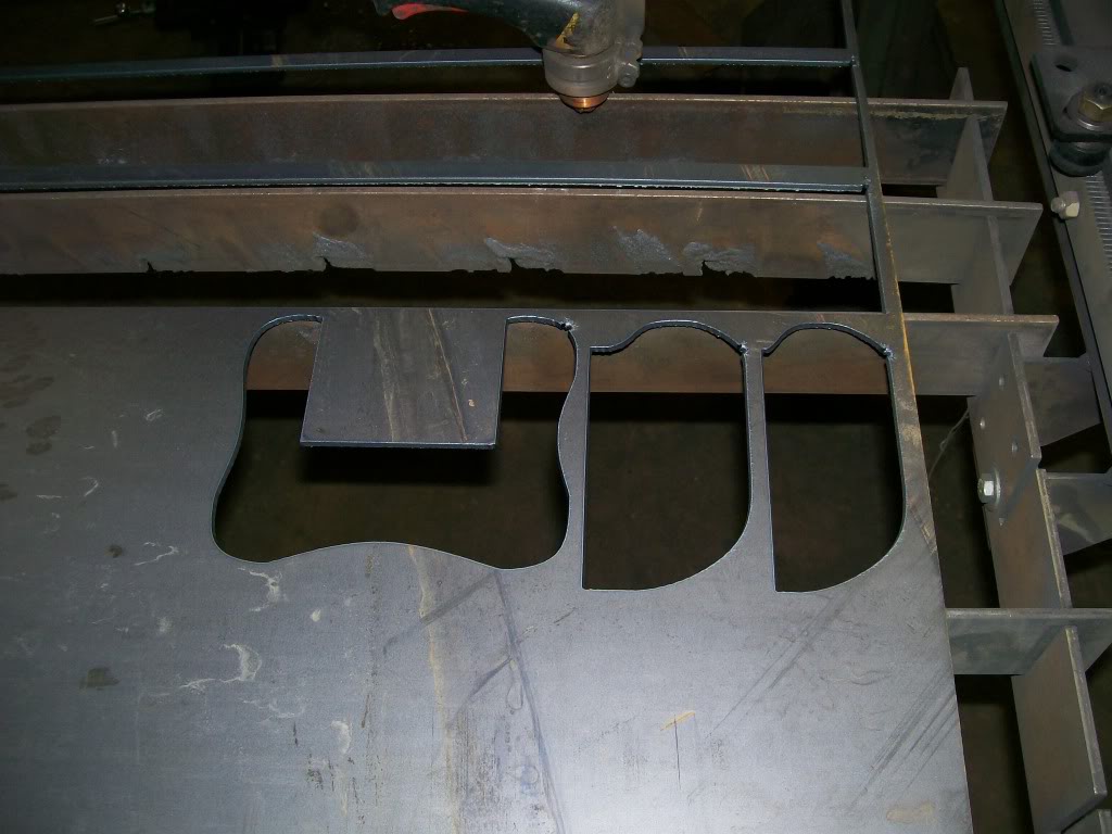
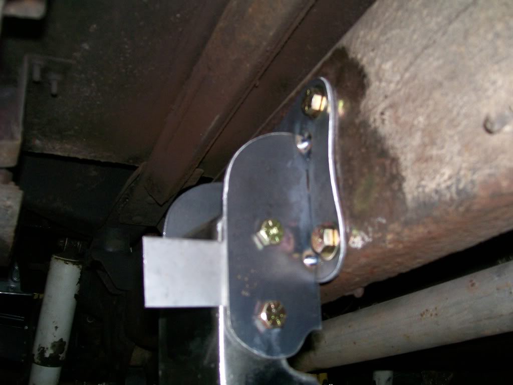
I mentioned part of the idea of the crossmember will help aid in the stability of the frame under the cab. I figure if I bolt the mounting plate to the frame with the bolts far apart from top to bottom, this will give the best way to achieve what I'm trying to do.
With that in mind I cut the plate to reach from top to bottom, and I made the plates so I'd have an area in each corner to drill for the mounting bolts.
As a side note.....I could just weld the mounting brackets that bolt to the crossmember to the frame and eliminate the mounting plate. I can't emphisize enough the idea of trying to think a couple steps ahead when building a project. I know when I get to doing engine work I'm gonna want to slightly readjust the way the engine sits right now. If I weld the brackets to the frame I'd just have to cut them off later. By bolting the plates to the frame I can simply unbolt and readjust the crossmember at that time.
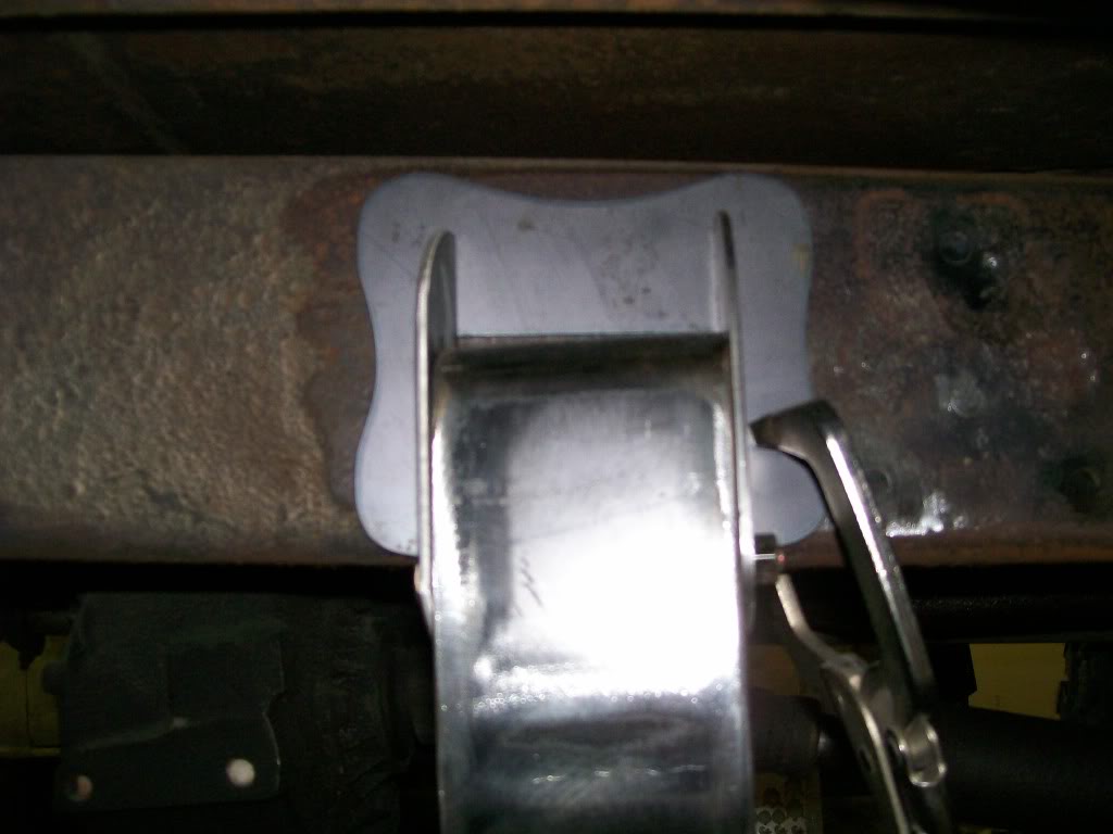
And a side view of how it'll attach to the crossmember. In this case I used two bolts vs one bolt on each end. Using the two bolt method will provide a solid lock to the brackets, then to the frame. One bolt would have created the possibility of it being a pivot, vs two bolts that will be a solid lock.
In this last picture you will notice a piece of sheet metal sticking out. Hmmmmm? Going back to when I made and welded the shock brackets I spaced the sandwiching brackets apart about 40 thousands of an inch. This way when I install the shocks I don't have to deal with a too tight of a fit. Same here. I simply stuck a piece of sheet metal between one of the sideplates and the crossmember. Now when the welding is done I'll have just enough space to easily slide the crossmember into place.
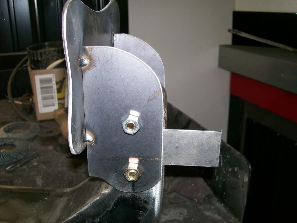
1-23-2012
Thanks Harold_Ray, I'm glad you like. Bright was my first priority. I had just finished a restoration of the Camaro in the back ground of the pictures. The walls do get dirty with all the welding, grinding and sanding. I have to cleanafter big projects, but it's worth it.
Wildspear, these ideas of stuff like the small piece of sheet metal, is from years of "Grrrrrrrr".

Thanks for checking in LA-Sahara, When I started this thread I had no idea of how many would be following it.
Since we've touched on the idea of putting the piece of sheet metal between the crossmember and the side plates, I had a picture that shows the process. Keep in mind, metal such as these side plates, do return to their original starting point when bent to tighten against the crossmember after removing the bolts. With this gap the paint won't be scraped off when I reassemble after painting. Much more gap and the metal would bend and hold it's shape, we just have to stay within this margin and the metal will work with us.
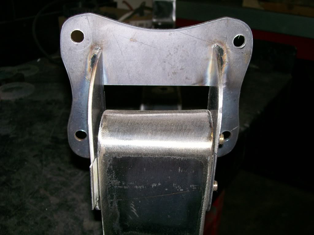
I'm finally starting to drill and attach the hangers. Since in real time I'm a little further into the project I can fortell that there will be slight changes to these hangers, but nothing dealing with the mounting of them, so this picture is true.
There is one aspect of fabrication that can not really be taught, it is making the decision of what metal thickness to use when creating something. For instance, the crossmember, if I was going to build a crossmember that is just going to go from side frame to side frame, 1/8" metal in a box design would be fine. In my case I knew I'd be supporting the weight of the transmissionand transfercase, so I used 3/16" on the vertical sidewalls.
Sounds simple, yet we have another factor to throw into the mix. I had to decide the actual height of the side walls. I know that if make the sidewalls on the crossmember 2" vs 1" tall, it will be much stronger. So not so much the thickness but the cut/load bearing height of the wall is also a consideration.
I'm not done yet...... I had a choice when I cut the sidewalls of the crossmember. I absolutly needed the two drops in the upper part of the crossmember. I did not however need the drops to show in the bottom of the crossmember, I could have simply gone straight across and saved alot of fabrication. Just as a chain is only as strong as it's weakest link, this crossmember would be only as strong as the two narrow wall areas if I'd have gone straight across the bottom.
Last but not least, it just looks darn good with the drops in the bottom.
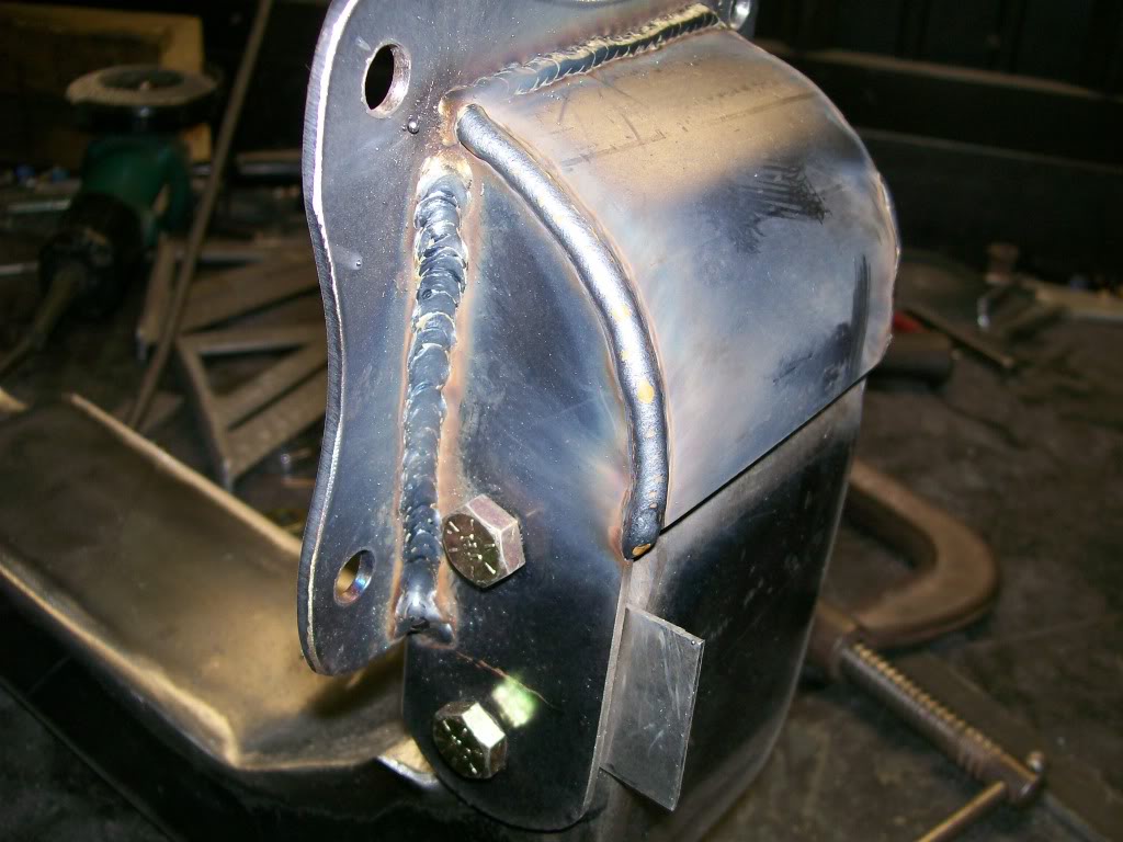
I started the thickness conversation because I could have used 3/16" vs the 1/8" that I used to build these hangers. In this case I knew I was gonna have all the pieces welded close together. Meaning I'd have 90 degree angles close to the mounting bolts. With these welds running close to the outer parimeter The structure would be strong in itself.
With the upper cap welded on here, you can see how it's all tied together now.

Ultimate classic truck right there
Posted by CCmyVW on 12/26/20 @ 4:17:42 PM