You must be logged in to rate content!
16 minute(s) of a 620 minute read
11-4-2011
There is a difference between the two. Electrostatic can perhaps be explained by this illustration.
Ever taken a piece of plastic and rubbed it with a cloth, then when done it seems that the hairs an your arm when close to what you rubbed, where magnetically drawn to it. I know this is static electricity but, it is the same concept in electrostatic paint, it's another way of creating a static electricity effect to drawn to items together. As in the idea of painting, the paint is drawn to the item being painted in a static electricity manner.
Powder coating, although looks like paint when done is considerably different. As to where paint is a liguid sprayed from a gun, powder coating starts out as a powder. It is a very fine plastic powder that comes in a large variety of colors. It is applied through a gun designed to spray a fine mist of powder onto the item being coated. (I'm not sure however if they use the electrostatic means of application with this though.) Once the powder has been applied onto the item it is placed into an oven, it requires high heat to melt the powder to a liquid. Once the melting occurs all the powder becomes as one seamless coating now. Depending on the amount of time in the oven you can have a semi-gloss to gloss finished when done. You now have a strong durable thin plastic coating.
Powder coating can be industrial or a home garge product, it all depends on the size of oven. If you want small brackets and such powder coated, you can get a kitchen oven. But for large stuff they have simailar to paintbooth sized ovens to heat the powder.
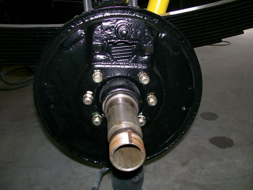
Just a couple pics of the braking. This backing plate, although it should last for many years without rusting now, does show why I fill the pits in most stuff that will be seen later.
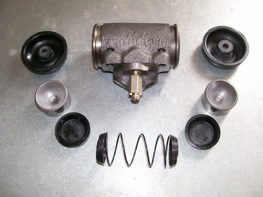
Let's take the mystery out of what's inside the wheel cylinder while we're at it. This is a brand new one, I want to spray a couple coats of spray can black on it just to help it live a little longer so it's easier to disassemble and tape a bit then paint.
I laid the parts out in order. In the center is a spring, very little tension, just there to keep the internals snuggly together and in alignment. The two rubber cup like seals. Notice they have a lip facing towards the center. The brake fluid will come in from behind these rubber seals. At the same time the fluid will push these seals outward, the fluid will push the lips tighter to the steel wall of the cylinder for an even better fit when under pressure. Then the metal pistons. They are gonna be the mechanical force being pushed outward by the seals behind them. Then the outer dust boots. They have a dual purpose, one is to keep the outside dust from contaminating the inside of the cylinder. Two, there are short rods that go between the brake shoes and the metal pistons. These rods tightly fit into a hole in the outer boot. The boot keeps these rods in place.
Otherwise there is a bleeder screw, and a threaded area in the back where the brake line transfers the fluid into the cylinder.
11-6-2011
Sorry for the suspence, I'll get more pics tomorrow eve. (Monday).
I had a dog go through a situation, turned my life sideways for the last week. She's doing better now.
Cowboyup94 asked about the engine and transmission. We've covered it before but I understand with all these pages it's alot to go through, I don't mind answering.
Back in 1985 I put a Chevy 350 with a turbo 350 transmission. The engine has lasted fine, I rebuilt it before I put it in this truck. It's basically a stock assembly with an aluminum intake. When the day comes I'll retain the 350 engine, perhaps have it bored to freshen the cylinders. Since I did a valve job back then, I'm sure the guides are beyond a simple knurling to bring them back to spec. Then I'm sure they'd need surfacing. Then valve grinding, then ect, ect, ect.
Anymore the cost of the labor for machine work on a stock set of heads isn't worth the effort or cost.
I see Jegs has a head and intake kit, very resonable cost.
So, when the day comes, the bottom end stays reletively stock, with new style cast iron heads.
Transmission stays the same also. In 1998 it gave out on me, I tore it apart and found a break in the case casting. I have some spare parts so I put together another transmission and been good since then. I'll just freshen it up for another 20 years I hope.
This project so far is just to rebuild all that time and rust has done to this truck. It's been a pleasure posting my progress and showing different ways of tackling many of the problems we will face as we try to restore and rebuild.
For me, I've also enjoyed tearing apart that of which I assembled years ago. I recall many of the stumbling blocks that I got tripped up on last time, and now conquering that of which I couldn't do before.
Thanks for all your support and encouragment.
11-7-2011
Jim1611, yes, mans best friend. I notice you have an occassional reference to being a believer. Whether yes or no, the dog is living by the Grace of God. It actually died on Wed. by all reasons. No heart beat, no breathing, her skin turned color with no heart beat, the heart monitor flat lined. I was called and informed, tear time. I made my prayer, about 15 minutes later, I was called and and when the vet. went to do an autopsy, the dog took a deep breath and her heart started again.
God tells me, NOTHING IS DONE TIL I SAY IT'S DONE. Praise the Lord.
She's been home since saturday, and doing great.
In my prayer I mentioned I'd give Him public acknowledgement, there you go.
Ok, I've got my mind back to the project again. It might be me but I can't focus well on a project if I've got stress or issues cluttering my mind.
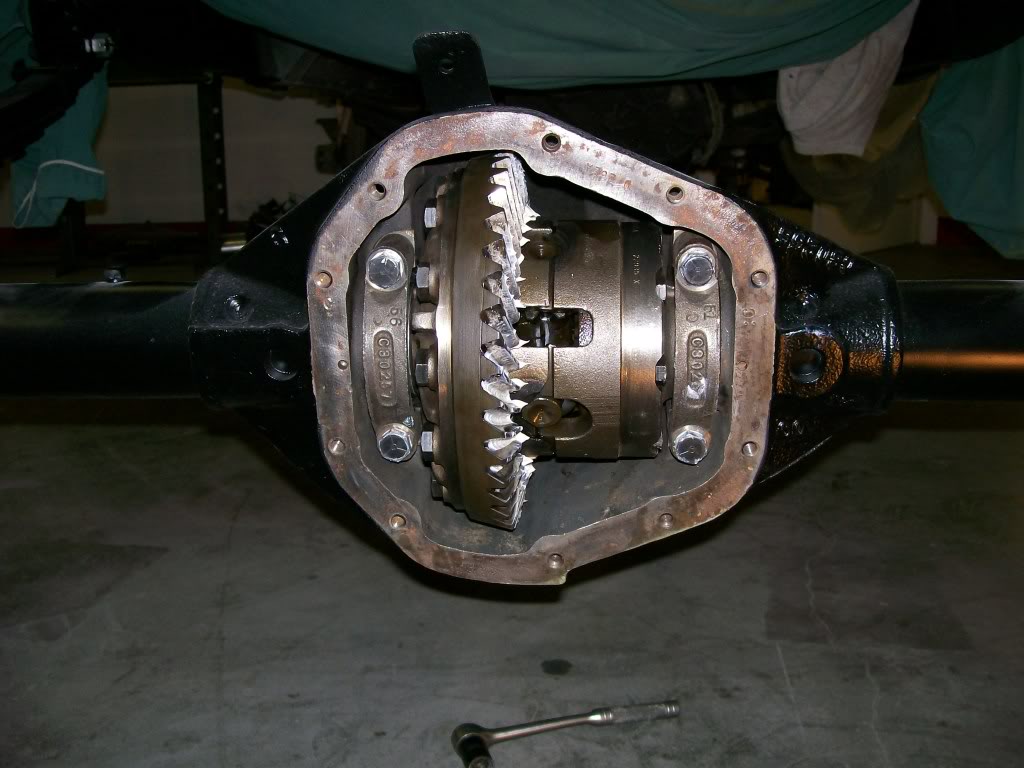
A couple months ago many of you will recall I went through the bearings, shims and gaskets in the rear axle. Once I got everything shimmed to the tolerances I wanted I removed everything I wrapped the parts in a bed sheet and put it all aside. Then I went about sandblasting, welding and painting the rear axle. Now that the axle housing is done and installed I get to reinstall the pinion and carrier back in the housing.
Before I can assemble I have to clean, clean, clean. Thers's been alot of sand flying around and I want ever grain out of there. So after a couple cans of brake cleaner and the air hose I feel confident I've cleaned it all out. I've greased the bearing races with a grease I use when assembling and engine. It stays where you put it, but once the oil, or in this case, the gear oil warms the grease it dissolves and is flushed out by the long term lubricant.
The pinion bearing are extremely important to lubricate before assembly. Imagine this.... The only way the front pinion bearing gets lubricant is when the vehicle is moving forward. The larger gear, (ring gear), slings the gear oil up to the front while moving. If you know gear oil, it's thick, it doesn't have much slingage, or slingablity.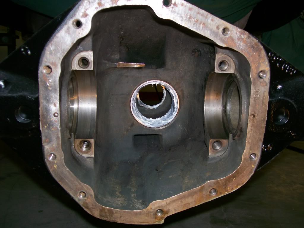
And here the pieces ready to be assembled. All pieces cleaned and lubed.
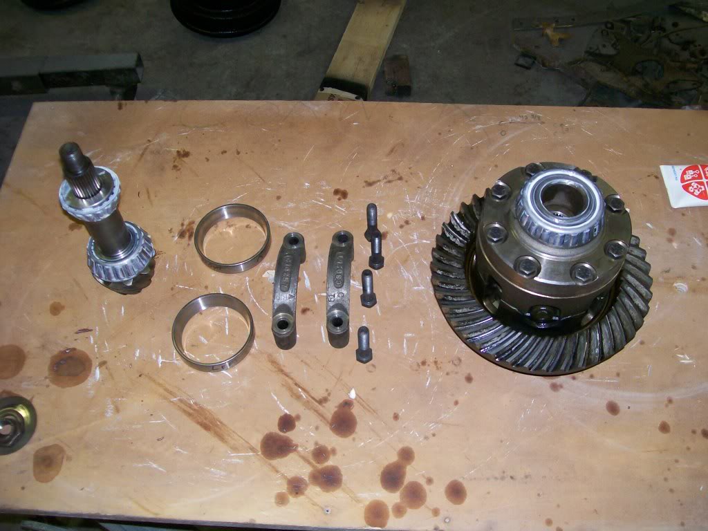
Everything fitted and tightened. Since I put new posi clutches in the carrier and I know they are sensitive to the type of lubricant used and I know the white grease may change the characteristics of the gear oil, I will remove much of the excess white grease on the ring gear before putting the cover on.
Note.... The side bearings of the carrier have outer races that are held in place by the caps and two bolts. Although the races hold their shape even after tightening the caps it is very important to use a torque wrench. Not so much for an even tightness but also for the bolts to stay in place.
In most situations we use lock washers or lock nuts, or locktight, or a matal tag bent over to hold the bolt in place. In this situation we just have a bolt. How does the bolt stay in place?? It is the stretch of the bolt. There is a certain amout of stretch that every bolts has built into it. It is this elastisity that keeps the bolt head tight against the surface. Every bolts size and hardness requires a different torque specification to use this stretch factor when assembling. I haven't used the emotioncon lately, so here goes. . Refer to the manual for the proper torque for what you're working on.

Here we are, final assembly.
11-8-2011
94yjstocklook. cherish the time you have with your dad, especially if you have similar interests. My dad had a passion for cars and trucks as I grew up, til I was able to start working beside him, then his job situation moved him away. We didn't work together too much, but he did put a never give up attitude spirit in me.
A saying I'll never forget is "can't, never did nothing". After hearing that every time I hear someone say "can't , I jump attention.
One step at a time the truck is coming together, it's a great feeling. I'm gonna finish up the brakes tonight. There are a couple technicalities that may enlighten.
Lets's get the picture to look at.
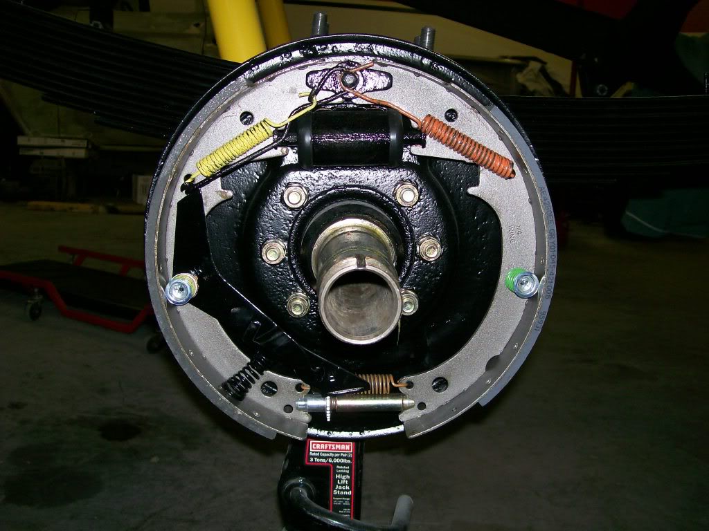
First... notice the rear shoe has more friction material attached to it. This has nothing to do with aerodynamics.
The brake system pictured is what was called a "duo servo" brake design.
Often times before this "duo servo" design with one wheel cylinder they used 2 cylinders. One cylinder on the top and one on the bottom. Each cylinder only had one piston though. So each shoe was pushed outward by it's own cylinder on one end and had a fixed anchor or the back side of the other cylinder on the other end. In this style both shoes had the same amount of friction material attached to them. Also in this old system was a manual adjuster that had to be adjusted by hand when the friction material wore down. Rather simple design.
Now the "duo servo" in the picture. We have one wheel cylinder with 2 shoes. At the bottom between the shoes is not a fixed anchor like the old design. We now have a screw type adjuster between the shoes.
Imagine rolling forward, then applying the brakes. Now when the brakes make contact with the spinning drum the friction will try to rotate the shoes with the drum. Now what happens is the drag from the front shoe is transfered into the rear shoe, and since the rear shoe is up against an solid anchor the rear shoe has to handle the two forces against it. 1) The force of the wheel cylinder pushing it outward to the brake drum. 2) The transfer of friction from the front shoe to the rear shoe. Hence, the term "duo servo. We now have a hydraulic force, combined with a wedging effect.
This system also created the ability for a "self adjusting" brake system.
Looking at the adjuster at the bottom, between the two shoes, it is a threaded screw with outer cogs (or a star wheel) around the outside. Notice the black arm that is resting just above this star wheel. Now, when you go backwards, and apply the brakes, the shoes now try to rotate the direction of the drum, counter clockwise. This movement will cause the rear shoe to shift counter clockwise, which if you follow the arm above the star wheel, it pivots at a point on the shoe. Now from there you'll follow a thinner rod up to the top. This thinner rod is solidly wrapped around the top anchor.
Ok, now in reverse, and applying the brakes, the rear shoe will move away from the top anchor, which in turn the thin rod, and the arm reaching to the top of the star wheel, will cause the star wheel to be turned by this movement. The star wheel is attached to a threaded internal screw, this rotating of screw will expand the adjuster, which will spread the bottom of the brakes apart. Now we have self adjusted brakes.
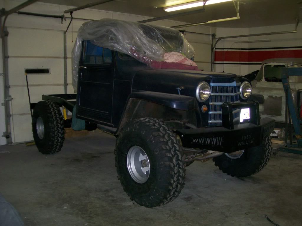
Ok, class is over. Now for a front picture of the truck so far, with the new tires. Honestly, I liked the width of the old Ground Hawgs, but I think these will do the job just fine though. With the lift that the new rear suspensiongave me, I definetly have to lift the front a bit. I am prepared, I have the new front springs sitting in the living room.
11-9-2011
Educational and entertaining....I would have done alot better in school if they'd have combined these two more often.
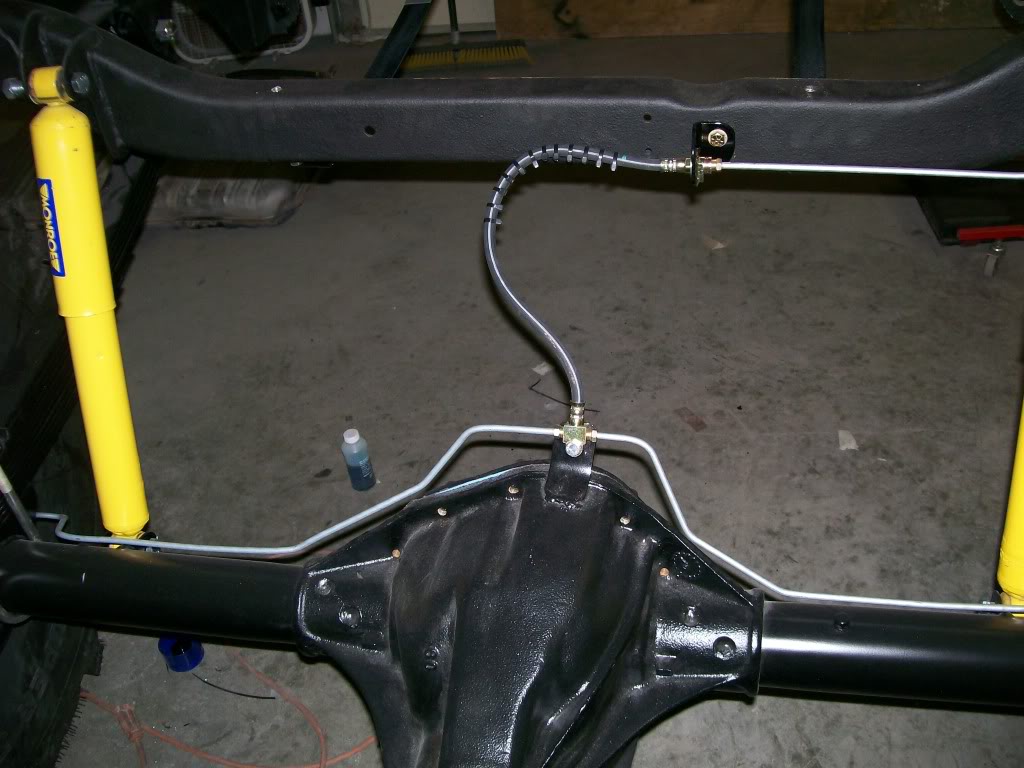
I'm starting to get a little excited here. Finally I'm putting the pieces back together. Now that the brakes are together I have to run the brake fluid lines along the axle and the frame. In this case I'm running 1/4 inch lines. With this size line you can bend by hand, but get too sharp a bend and you may kink it. There are many different benders to help make the bends with out kinking the line, you just have to decide which works best for you.
Another tool to get familiar with is the flaring tool, this allows you to cut the line to length and re flare the end.
Here is where decisions have to be made also. The decision of where you want to run the lines. In this case I have a solid mount in the center area. Keeping the line above the axle keeps it out of harms way. Once I dropped the line down under the springs I did clamp the line to the axle, then up to the wheel cylinder.
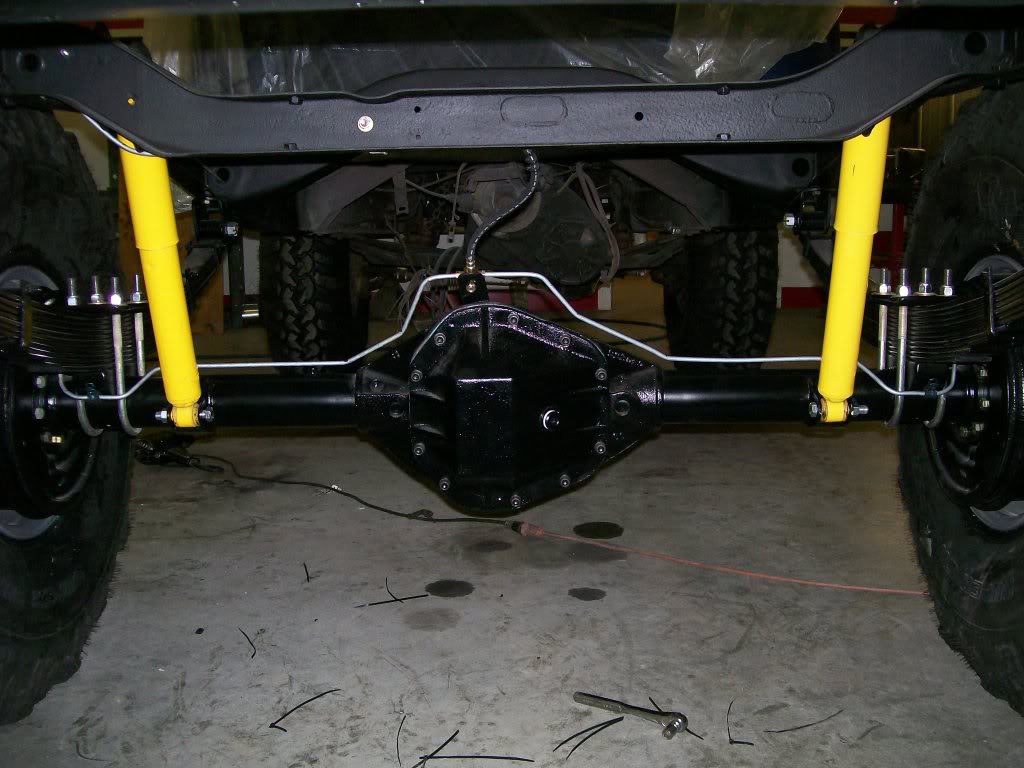
Along with the metal lines we have to deal with the flexible lines. These have different ends so the mounting on the ends will differ with each line design. In my case the original Willys design wont work for me. It's nice to have a cooperative parts store that will alllow you to look through the illustration book for what will best fit your project.
Another trick I do when I fear the line may rub against an object. In this case, if the flexline moves toward the frame when the suspension travels up and down. I'll put zip ties around the line in that area. I put enough to cover the area, but not too close together that I take away it's flexability.
Ultimate classic truck right there
Posted by CCmyVW on 12/26/20 @ 4:17:42 PM