You must be logged in to rate content!
15 minute(s) of a 620 minute read
8-23-2011
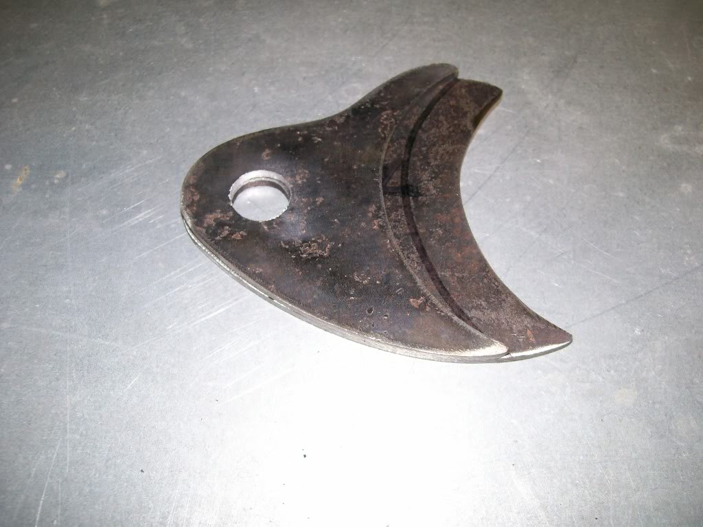
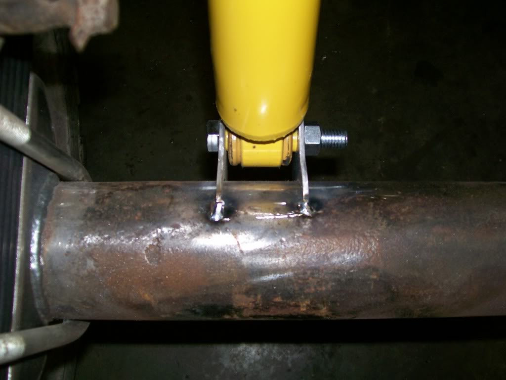
Got out to the shop tonight, I recut the bottom mounts. These will move the bottom of the shocks closer to the axle housing which in turn will create a little more space between the top of the shock and the shock mounting brackets.
These pics are of the mock up, just a pre assembly to check the fit of all the pieces. Once I'm convinced that none of the new brackets will get in the way of running the brake line or fuel line I'll do the final welding.
This pic is the new one laid on the old one. Another choice would have been to use the old ones and redrill the hole forward. Then I would have to regrind the outer shape and blah, blah, blah. For my tooling, recutting new ones was much quicker.
This pic shows how much closer the shock is as compared to a pic I posted a couple nights ago.
8-24-2011
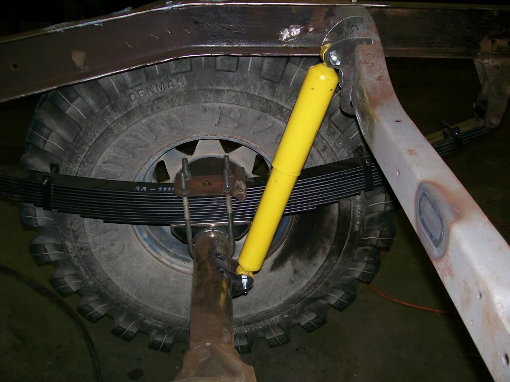
Simple picture toinght, I got the fit I wanted.
Nothing fancy, just a little change from the factory.
8-25-2011
Nah, we never got into primers and paint. Maybe I'm old school, maybe I just have some materials left over from other projects but I'm gonna use a acid etch primer. After this primer dries about to the touch I spray a primer filler on top. This primer filler uses a hardener that once is dries it does not shrink which is great because you can spray a couple coats at a time and it will fill deep grinding scratches. Once the primer filler is done, 3 coats of Eastwood poly urathane satin black. Yes, I know they have the chassisblack with ceramic particles ect. Anyway, this should hold off the rusting issue for years to come.
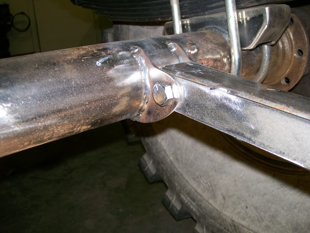
Let's go back a few pages in this thread. I mentioned one problem with welding is while you're welding and if the piece you are welding is not well supported, clamped, or mutiple tack welds it will have the tendency to shift or move slightly, this sucks. Try this, take piece of metal, put it on another piece of metal in a 90 degree arrangement. Don't clamp, don't tack, hold it there with good gloves and weld a bead. You will feel the pull towards the bead side as you are welding, then as you stop the welding you can feel the piece in your hand retract back to where it was when you started. Problem is, it never goes back to exactly where it was when you started. Now, double the problem, to axle tabs to weld to the axle. Two times now of the tabs gonna move as I weld. I'm alittle fussy, you can tell that already, I want the tabs to stay perfectly aligned, and I want them to be about 1 45/64" apart. The shock mounts themselves are 1 11/16", 1 44/64", I don't want to weld, then take a hammer and bend them back the desired fit.
The hunk of metal (spacer) in the first picture between the mounting tabs solves most of the problems. It is 1 45/64", it has a accuratly drilled hole, it'll hold the mounting tabs parrellel to each other, I can hold everything in place and chech for level. Now I can tack weld both the tops and bottoms of both tabs, recheck my measurements one last time, then weld with confidence. Now remove the bolts, remove the spacer, slip the shock in there with a speck of clearance, done. Don't worry, later I'll roll the axle back out, flip it upside down and I'll weld a cross strap across the two tabs.
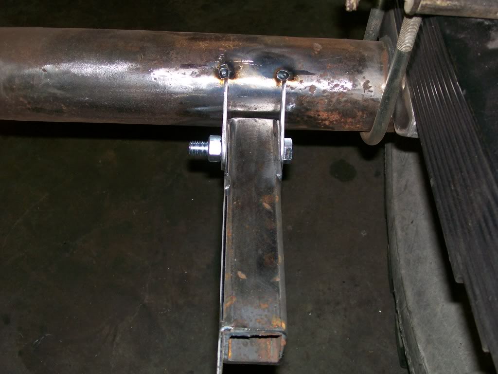
Now I can say "welded" with confidence.
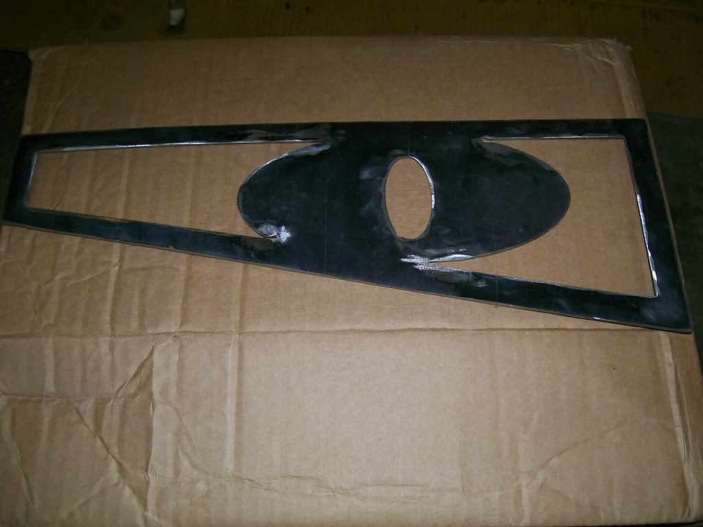
I was going through some hunks of metal, I found this one. This will be a part of the truck, and another one just like it. Any idea where this and it's near twin will be? Hint, page one of this thread has a bunch of w"s there now.
8-26-2011
94yjstocklook, I want to thank you for participating. You're on the right track thinking about bumpers though. When I built the front bumper it was an open book, I knew the basic design I wanted, but I had alot of space I could leave alone or, make something of it. Then I didn't like the idea of being stuck forever with the same look. Sooooo, I made replaceable sections. Where you see 5 W's or teeth on each side of the bumper, they are removable. The picture below shows allen head bolts around the w's/teeth. This is just plate with this cut. When I want to change the attitude of the front bumper/truck I can put in something like the picture you tried to guess. When cleaned up and painted, the one you guessed at is an eyeball. So now any image I can cut into a plate to fit, is the new attitude.:
 cool:
cool: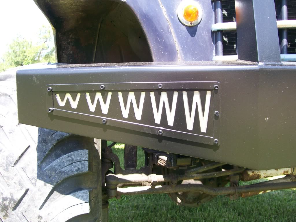
Hmmm, it's hard to explain. The outer ring you see with the bolts going through it is just a outer parimeter ring, it adds strength to the opening in the bumper. Then the bumper itself which has an opening cut into it. Then a plate with the outer parimeter as the "eye". Instead of the eye, I cut w's into the plate, then behind it is a clear coated aluminum plate. All sandwiched together. The posted picture does'nt do it justice. They look like painted W's, it's not the case.
The eye will replace the "W" plate and a plate painted white, maybe with blood shot red marks added will be the backer plate behind the eye.
Once I get back to it I'll post a pic showing the stack of plates. Just think of the possibilities.
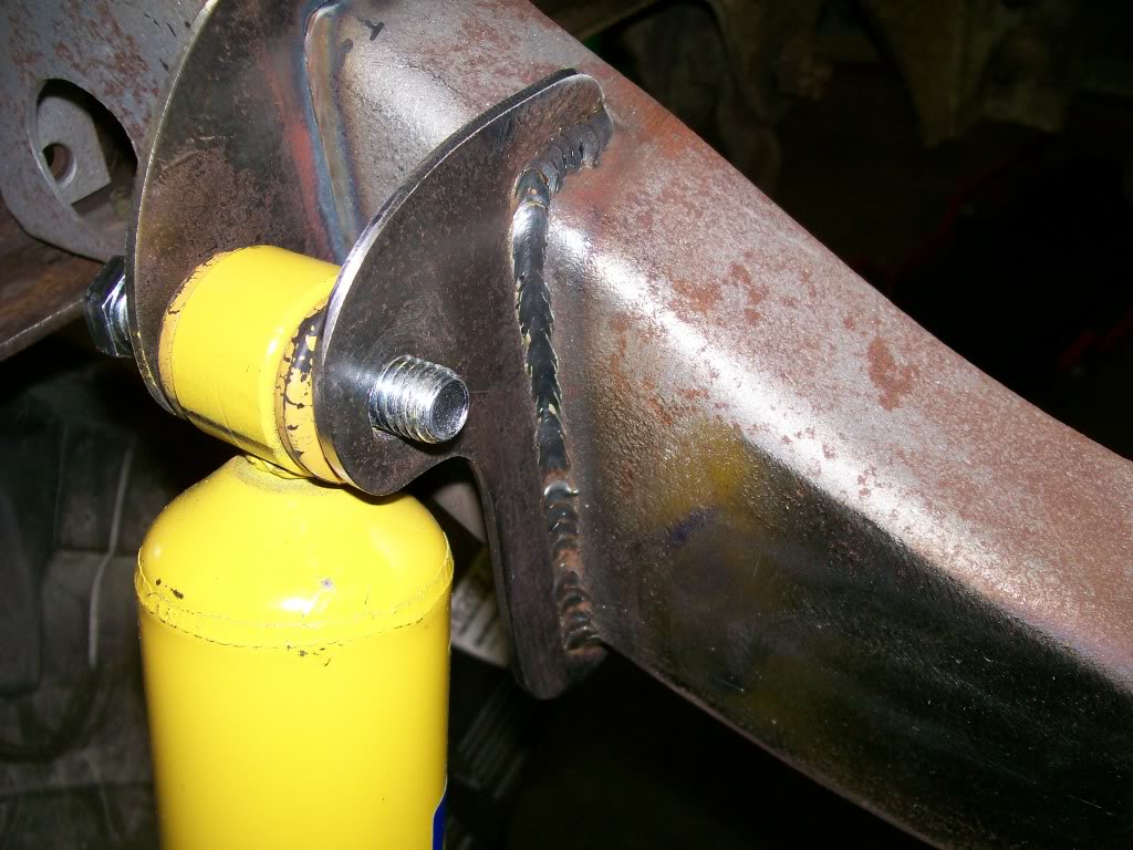
This is where we check off another piece of the project, once it's welded it's a done deal. We also say "thank you" to who ever invented the wire feed welder (MIG).
These top brackets as I mentioned before were a pain. Dealing with the top angles, bottom angles, the distance between the two plates of which were different than each other and on top of it all, having the mounting bolt level from mount to mount.
With as much as we like to have the perfect fit we have to be reasonable, we still deal with hand fabrication.
Here's where the MIG welder comes into play. Ideally a small gap is perfered, the wire can really get between the two pieces being welded and get a great penetration. It's not a perfect world so we deal with what we have.
In the first picture before the weld, we go from total contact to a gap of 1/8 to 3/16. We have about 8 inches of weld to do. I don't know what the experts advise but on a vertical weld I always go from top to bottom, it might be just how I learned. Starting from the top it's a sharp edge, too much heat and you'll burn right through. I'll start with a couple stitch welds to begin a slight material build up, then I can hold the trigger and weld downward. UNTILLLLLL the I get to the gap, if I continue I'll burn right through. without pause I have to start a fill process. This will be back to stitch welds in an upward arch from side to side. I can control the fill and control the heat and work this all the way down and around the corner.
Oh, and there's that spacer I used on the bottom mounts.
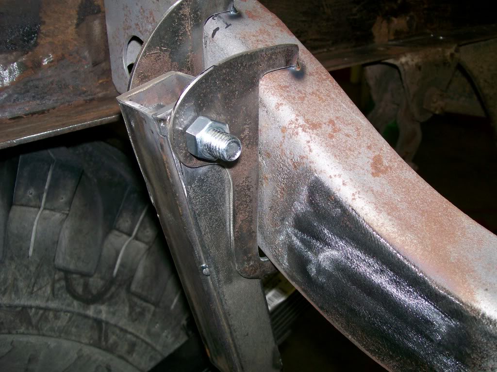
Here's the end result. You can see the switch from one type of weld to another. This is the great thing of the MIG welder, so fast, so clean, so adaptable.
8-27-2011
Mazdarx, thanks for taking the time to go through the whole build so far. The spring work that is being done is just to replace the old 61 year old springs. I've been running a spring over axle system for years, so the height won't change much.
When I did a mock up with the new springs, the rear did sit higher than with the old ones. I still have to put the bed back on, I hope the weight of the bed will settle the rear down a bit. I do have a set of new springs ready for the front. They are 10 leafs where the old one in there now are 6 leafs. Once the rear is settled I'll work with the fronts to get the truck sitting how I want.
Tire wise, the size is about the same. Like I mentioned previously they don't make the Ground Hawgs anymore. They were 40" tall. The closest I found was 39 1/2". It almost seems that even 39 1/2" tires are getting hard to find so I got them as soon as I could.
If I went any taller I'd have problems with full turns, the tires would contact the front fenders right behind the tires.
8-28-2011
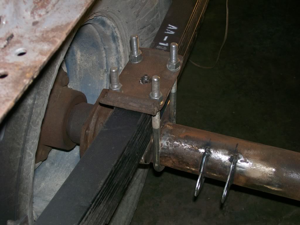
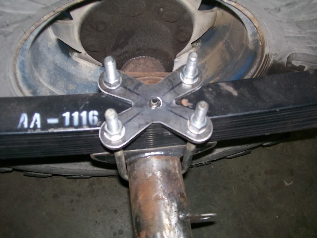
Now I'm gonna move on to the plates that hold the leaf springs to the axle. The ones I've been using are the originals. Over the years the have been stressed by rust growing between the springs and the plates. One problem I had about 5 years ago was these old plates became so deformed that they started to bend around the sides of the leafs and put stress on the u-bolts and broke one. Now when you see the u-bolts and they don't look like 26 years old, it's because I replaced them all when the one broke. So, it's time to upgrade. I've got a plan for new ones, follow along and we'll work with 1/4 flat steel. We'll learn how to put a 45 degree bend 4" long without a hammer or using a torch to heat the metal red hot. Ok. let's get started....
Two pictures here, lets see what we're trying to get rid of.

 Everybody likes lightweight repairs, so here's pretty and lightweight.


8-29-2011
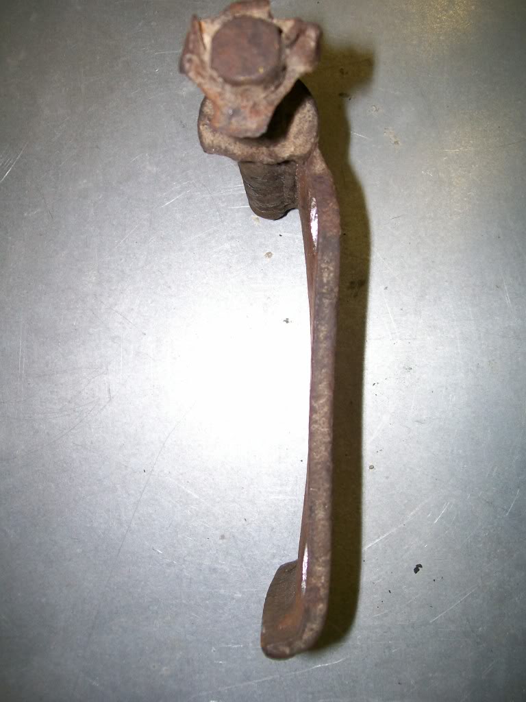
hallsofstone, Thanks for the feedback. I was just messing with you all. You are sooo correct. The upward bend at each end of the plate plays a very significant roll in keeping the plate from warping over the edges of the leaf springs. I'm not exactly sure as to why my old ones just lost their strength. Age? Rust? Fatigue? My issue is that I don't want to deal with it again. I'm planning on this truck doing it's chores for and other 20 years if possible. I want the same plate system, I need the rolled up edges for the strength you speak of. I considered larger washers under the u-bolt nuts so the load would be spread across a larger area of the plate, but it just seems shy of what I was looking for, sooooo. On to the torchmate I went. I'll post the process of the new idea, the mini plate you see in the pic is part of the finished product. Once again I'll walk through the drilling, cutting, welding process. I hope this is helpful for future projects for some of you.

Close up of the old, the weak and the ugly. (Reminds me of a movie.)
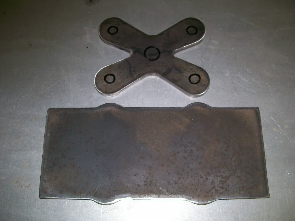
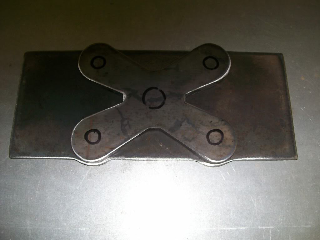
You've all seen the torchmate in action already. Here are the two plates I cut. By this pic you probably already can tell somewhat how this is gonna fit together.
8-30-2011
It's time to start some fabrication. The torchmate did it's job, now it's time to drill. cut, shape and weld these pieces. By the first pic you can see I've decided how the top plate will be reinforced. There were many ways to go about making the reinforcement plate. I didn't want to just double up the material, the challenge was to build something that would be strong and also be appealing to the eye. The larger piece in the picture is gonna be smaller when finished, at least length wise. One rule of thumb when you are building and fabricating is to be material safe. When possible cut the piece larger that you need, then grind and cut down to size.
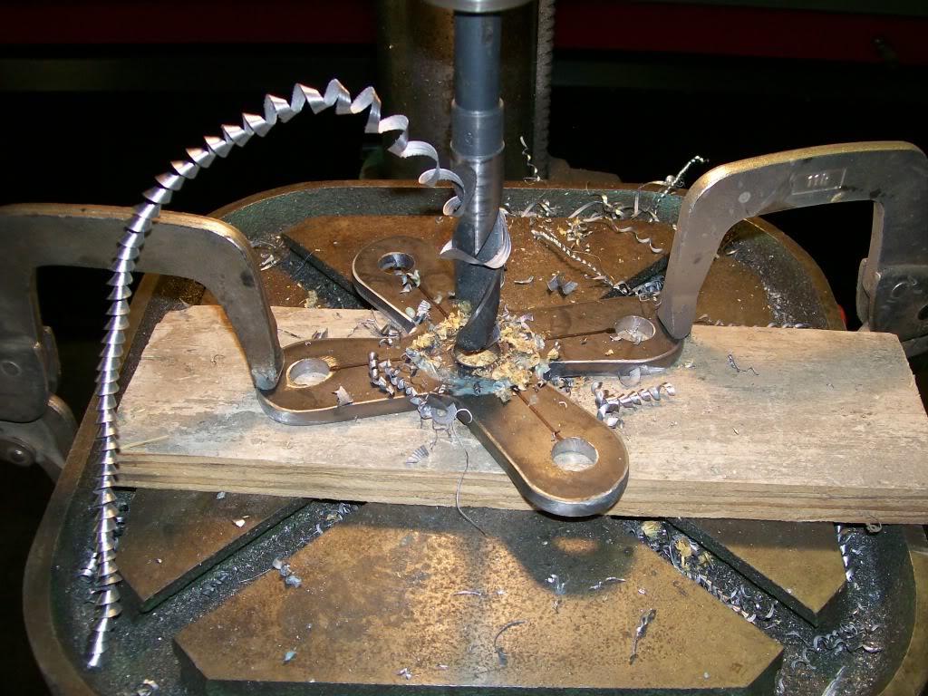
First off I'm gonna drill the necessary holes in the clover. The center hole is drilled to it's correct size 5/8". I don't know about any of you all, but when I have to drill the other 4 holes I can measure and mark and measure and mark then center punch and drill. Sure enough I'm gonna be off just a slight bit. Now I'm ovalling a hole to get the fit I need, grrrr.
 . The only remedy I have in most situations is to drill to a slightly smaller drill size than the final hole size. For instance, I need a 1/2 " hole so I'll drill to a 7/16. This will give me a good idea of how close I am. If one hole is off a bit I will now either file or use a small cutter in a drill to oval the hole closer to the final fit. Now I'll run the 1/2" drill through the holes. The one that was off will now be rounded to the 1/2" size. I also like it when the drilled material comes out as one long piece.

Ultimate classic truck right there
Posted by CCmyVW on 12/26/20 @ 4:17:42 PM