You must be logged in to rate content!
25 minute(s) of a 636 minute read
6-28-2017
Got my gaskets cut out in Viton:
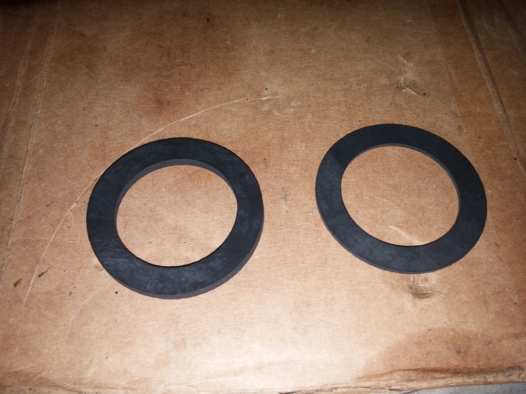
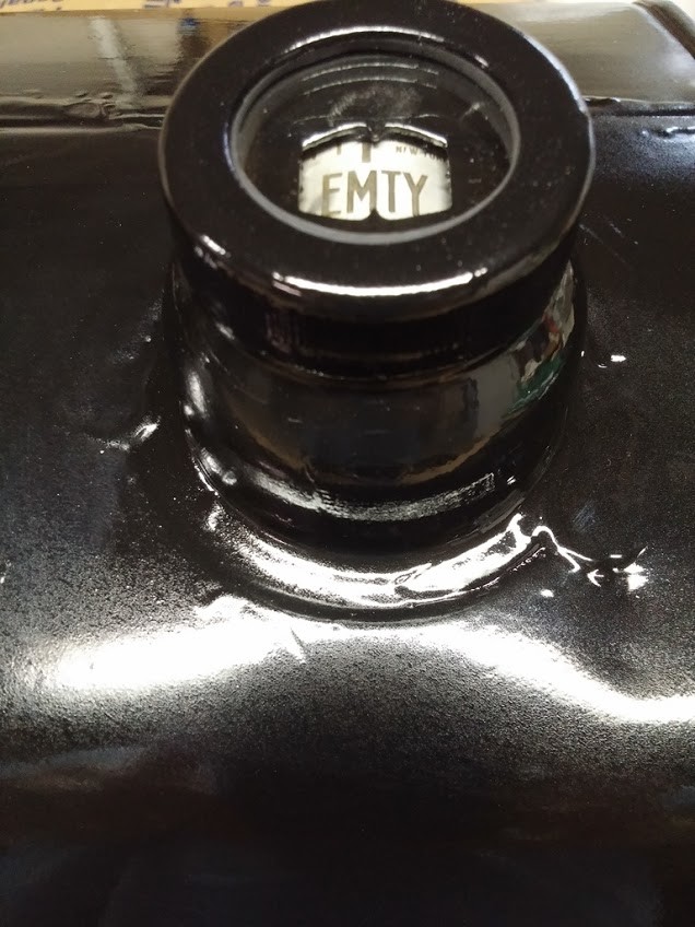
Installed the viton Gaskets vs the Cork for the gauge
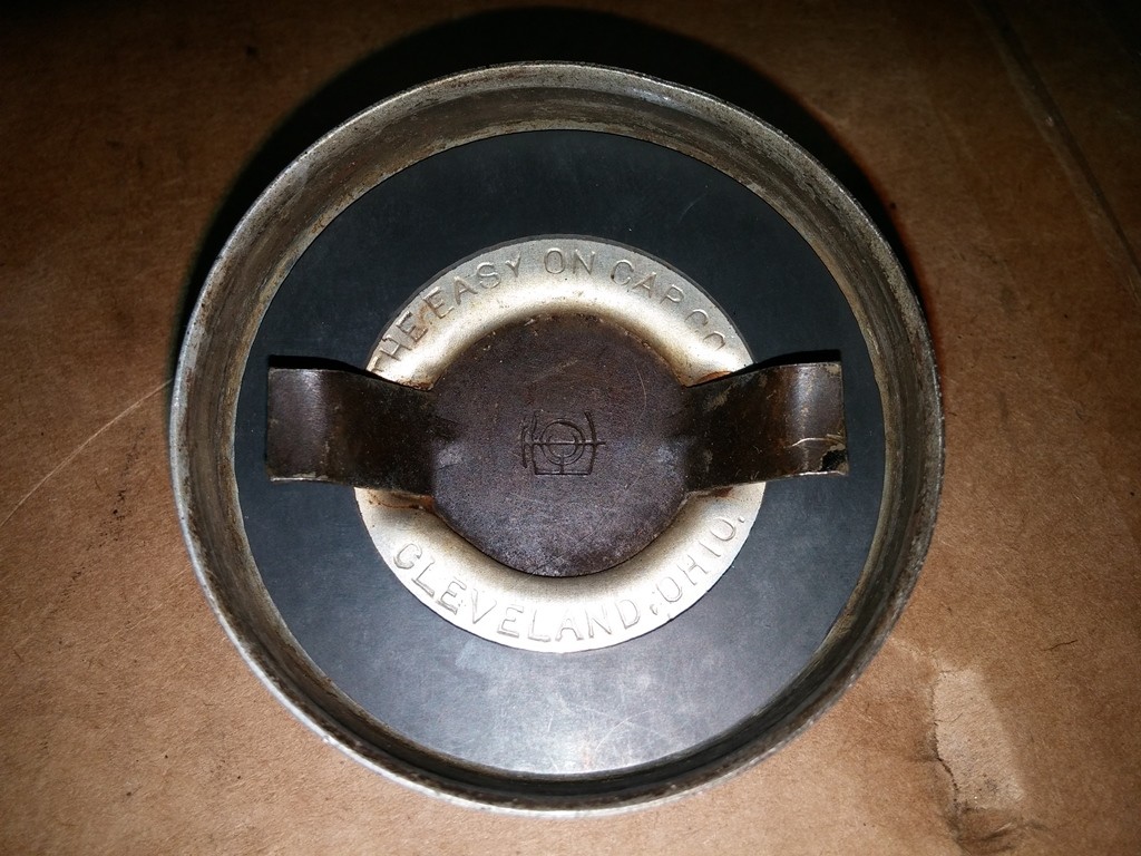
Cleaned up the Cap and replaced the worn out paper with a Viton as well.
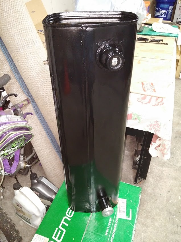
Fuel Tank Back in 1929
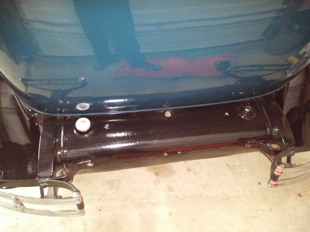
7-24-2017
Ordered some lacing from TFS, and finally got it in. Took my time and removed the old, looks Original lacing from the radiator and Cowl. Going to strip down and prime/ paint the black sections of the radiator/ support before i lace it back up. Removing all those little rivets was a pain. Removing the lacing from the cowl was pretty easy, i removed it in reverse of the installation instructions.
Now on installing the Lacing on the Cowl, How far/ close towards the center brace/ pin should i take the fabric on the lacing ??
Looking at this Cowl Lacing picture, you can see that the lacing fabric was past the third hole out from the center. so about 1.5-2 inches. is this correct or should i put the fabric all the way to the metal when i push the core through and bend it over ?? Lacing all the way in & up or lacing out from the center past third hole
how is everyone else doing it ?? the TFS instructions do not spec out how or where to do the fabric on top the cowl
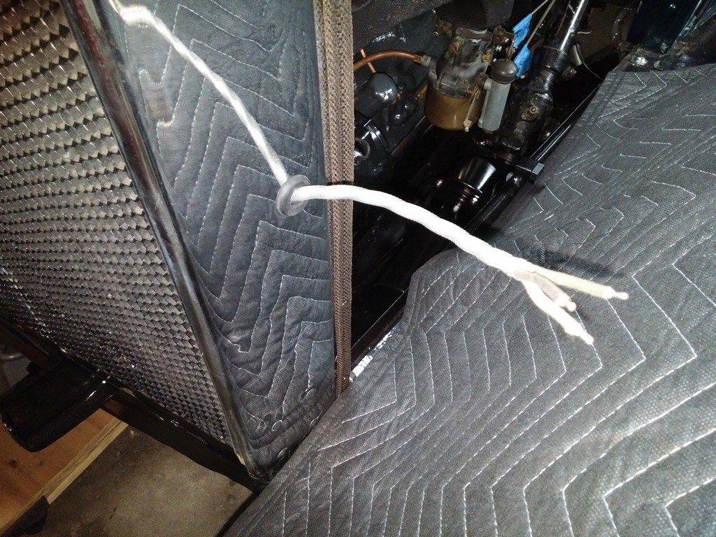
OK, laced up my cowl:
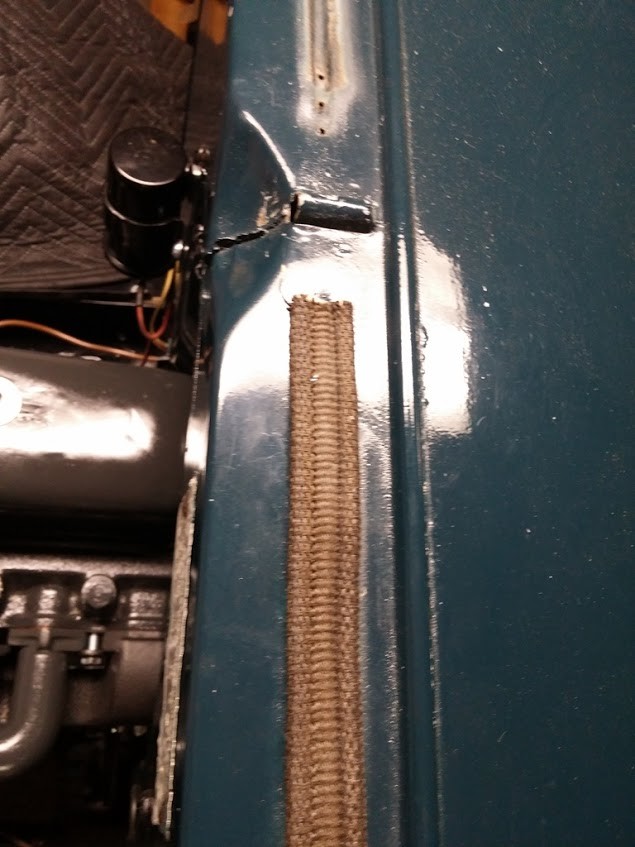
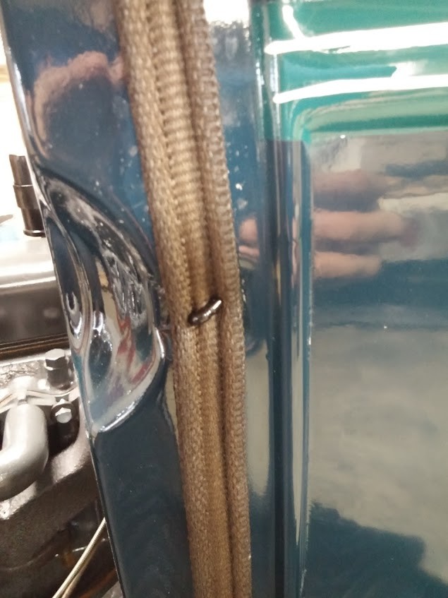
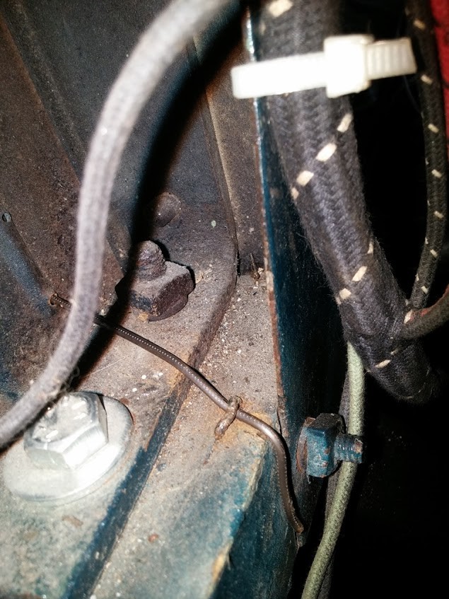
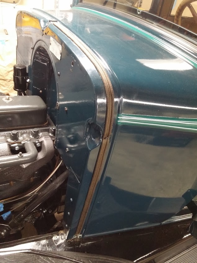
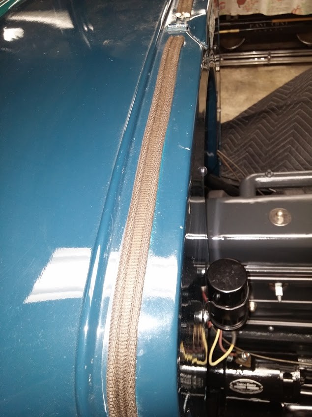
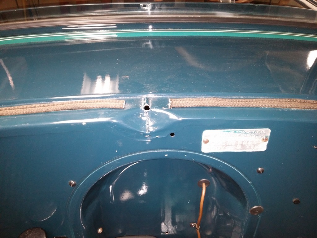
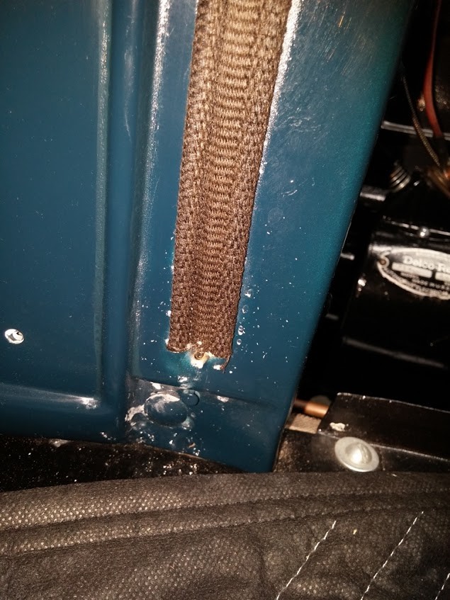
Was really easy to do, only pain was pulling that wire back on itself up through the top of the cowl, too some convincing and working, but got it done. have to say it looks really nice, I am really happy with it.
Stripped, primed, and painted the bottom of the radiator shroud, as well as part of the radiator brackets/ housing.
Then installed the Lacing on the Radiator. this was really easy followed TFS instructions they sent, and went smoothly.
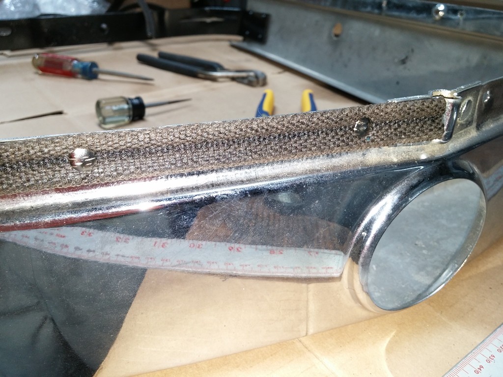
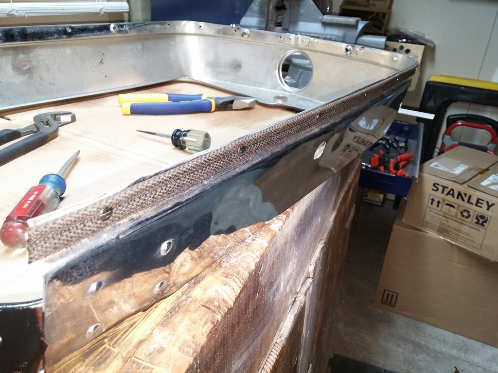
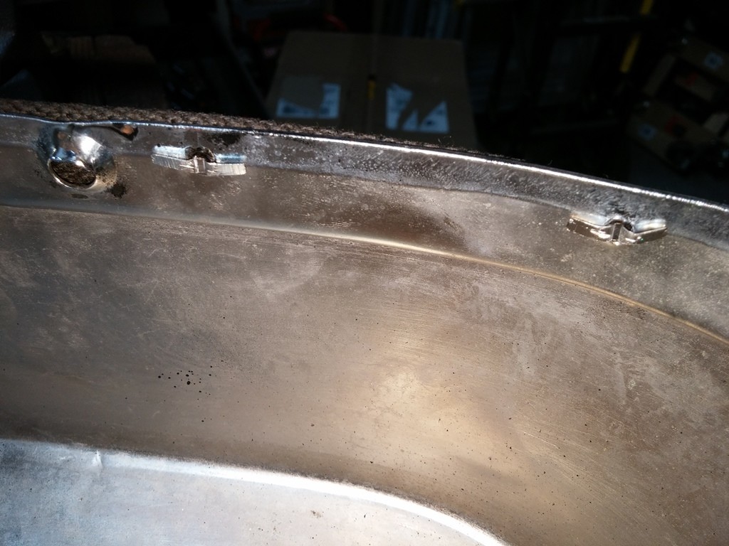
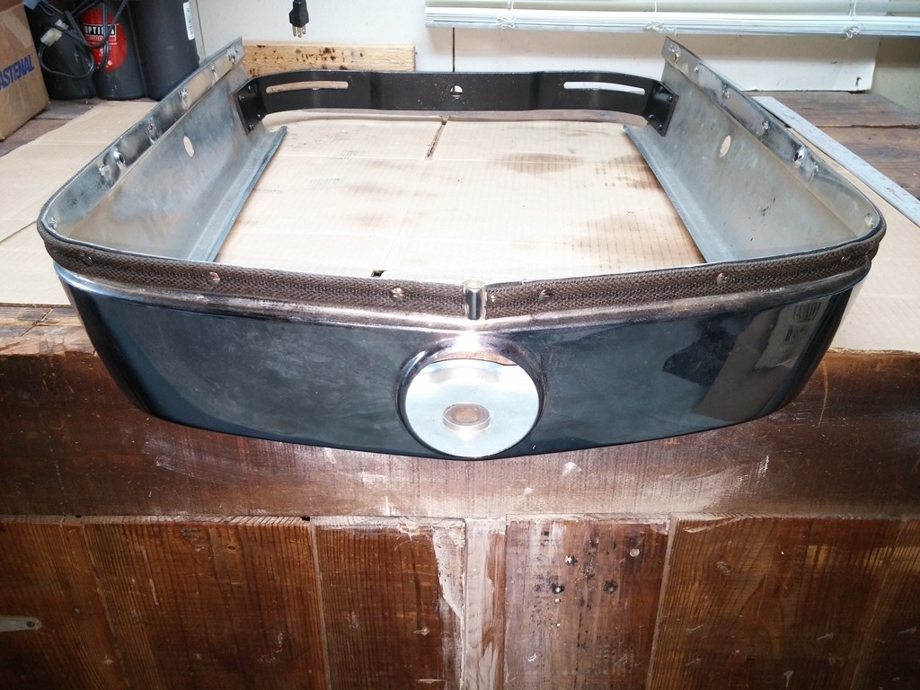
This Lacing went on super easy, and I am very happy with the outcome.
7-31-2017
Well got the Radiator put back together. was enough slack in the fabric to pull it down slide in screw, and then pass it through. took my time to make sure i did NOT damage anything i have already done.
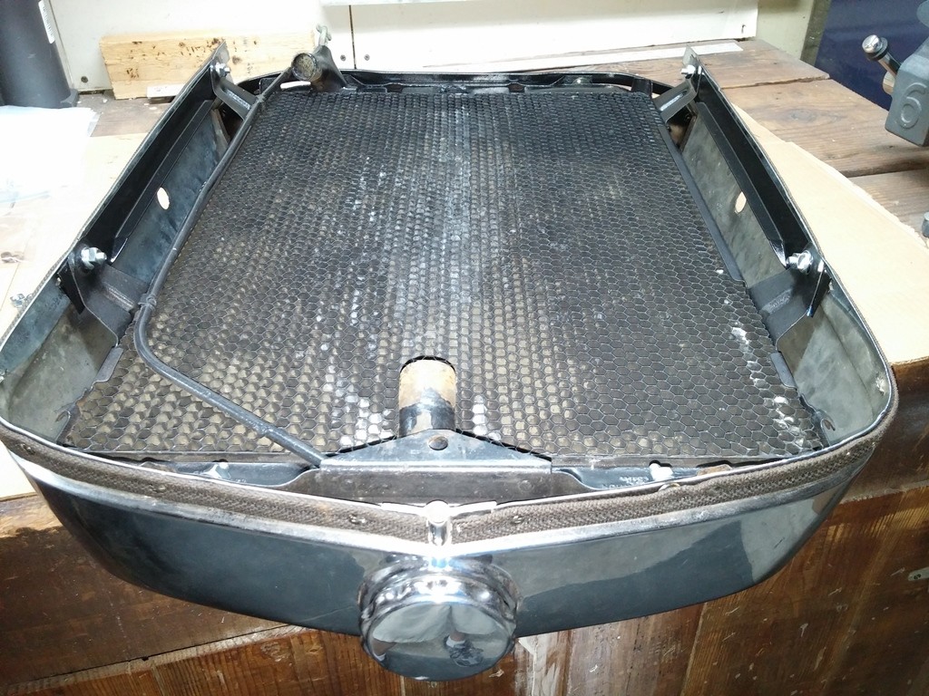
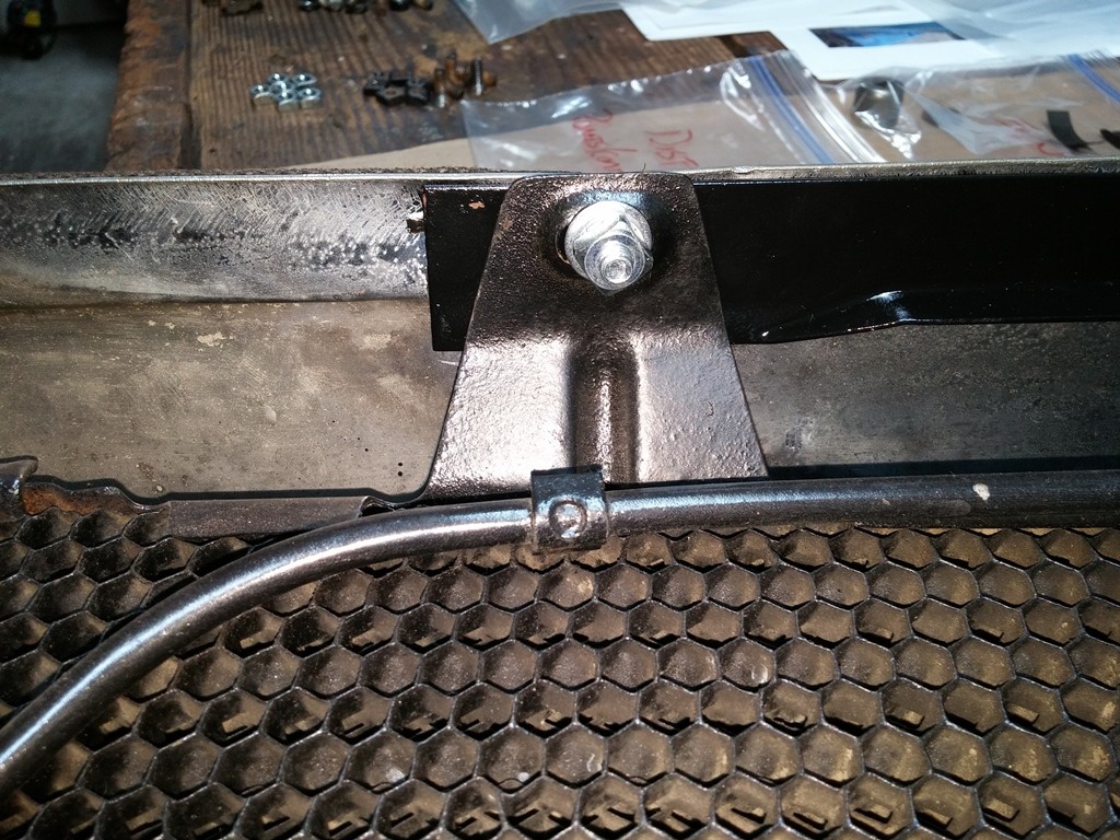
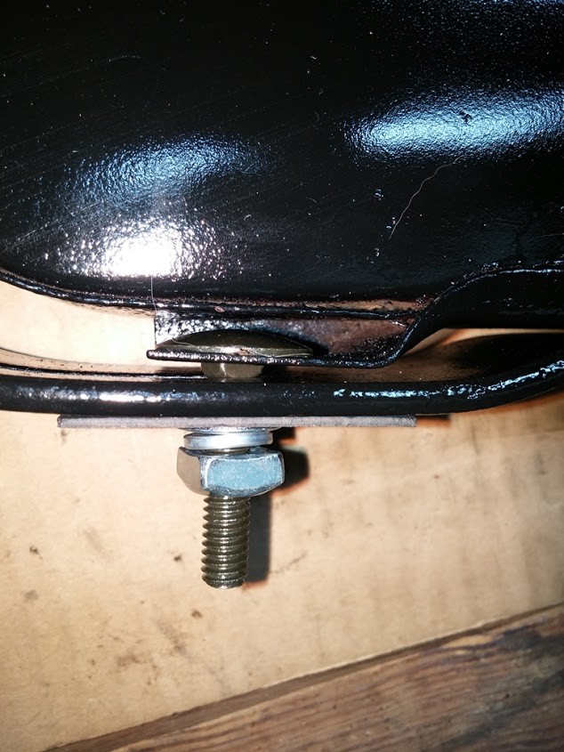
Wondering if anyone has any pictures/ layouts of HOW the wiring and cables are routed, where and how they are secured along the firewall, and where they go through the firewall or how they go.
Trying to get the spaghetti and cluster fudge under the dash and on the firewall inside cleaned up. they just ran wires/ cables where ever !!
Thanks to Bare Feet for the reference Photos, i spent about 1.5 hours last night starting to work on cleaning up under the dash & firewall.
I reinstalled the Speedo that I had JY Dog Fix for me, Thanks !! Replaced all the misc mixed up screws under there. and then started cleaning up the wiring.
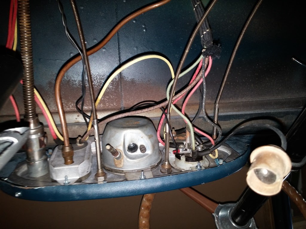
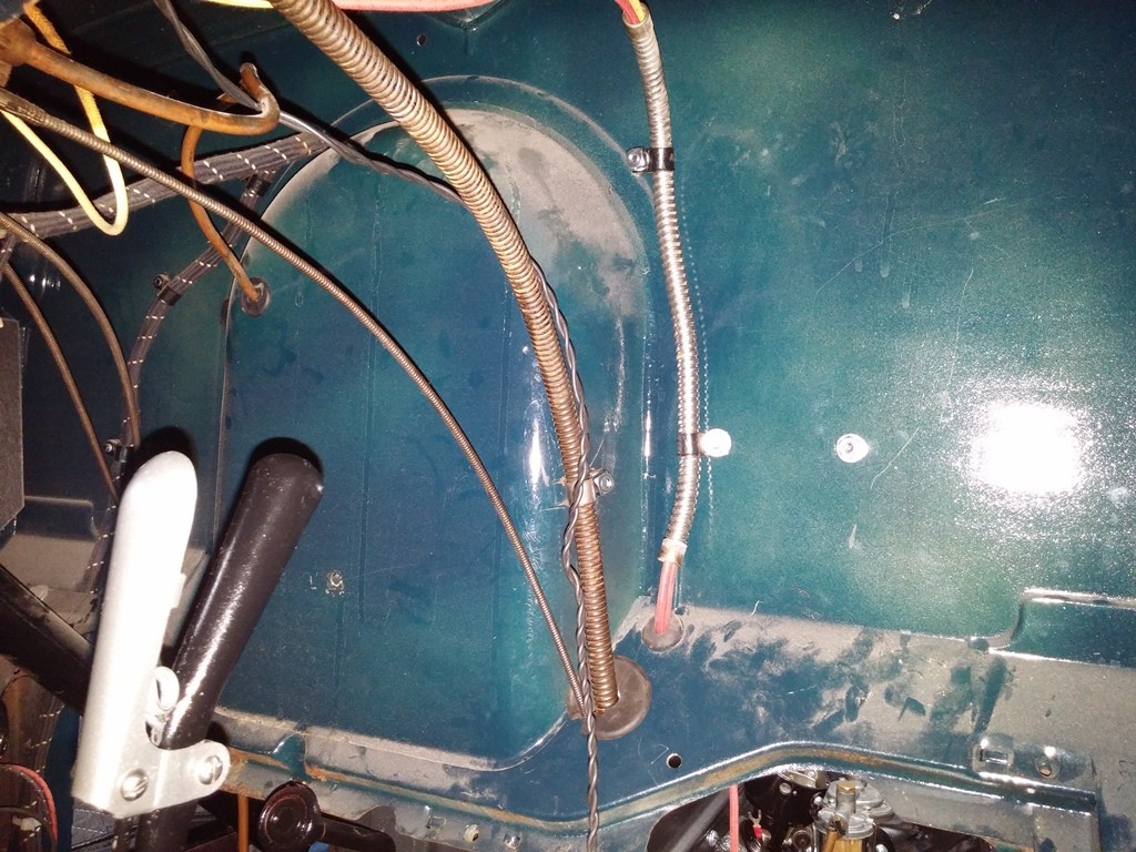
Notice the 2 Black Wires, looks like they go to the dome light switch
How and where are these guys routed ?? do not see them in the reference Photos ?? looks like the are along the sill plate coming from the back pillar, then they are just hanging from there up to the back of the dash.
Does this look correct for the Passenger side so far ??
Will start on the Drivers Side Next. Install the Speedo cable and secure that to the firewall as well.
Working on routing my wires under the dash as well as the Speedo Cable. Thanks to Bare Feet, looks like the Speedo goes down the back center of the firewall through a hold down w/ bolt. but WHERE does it go from there ??
does it go behind the pedals (between pedal rod and radiator side), or in front of pedals (between pedal rod and brake cross bar). are there ANY other hold downs/ clamps on the cable ??
any pictures of the proper routing would be appreciated. unfortunately the PO did not have it hooked up properly and it was hanging in limbo.
10-22-2017
Ok, removed the hardware and got the Bracket off...
So I installed it per the info and pictures above
Installed the Cable & Clip per the info from JY Dog above
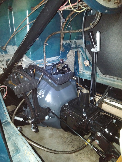
This is HOW I ROUTED the Speedo cable. does this look correct ??
Thought I would share, all pieces painted, New hardware installed and secured, once again thanks to everyone for their guidance and assistance with this !!

Getting ready to reinstall the Radiator and such and wondering HOW the wires run down the rail up front.
On the drivers side do they run up along the top inside of the rail over the steering box or down low under the box ?? I understand that the center hood Bumper also has a wire holder ?? where else is the wire held or secured ?!?
Pictures would be nice !!
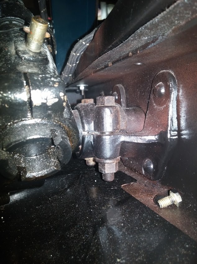
various areas ?? assume they are long the TOP of the Frame rail ?
where ? do they mount on other items or solo mounted ?? (do they mount on the backside of the hood latch mounting hardware)
Here is the routing I have as of now:
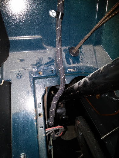
There is ONE Clip holding hte bundle on the wall under the Floor Board
Where to Put in the Clamps Down the Rail
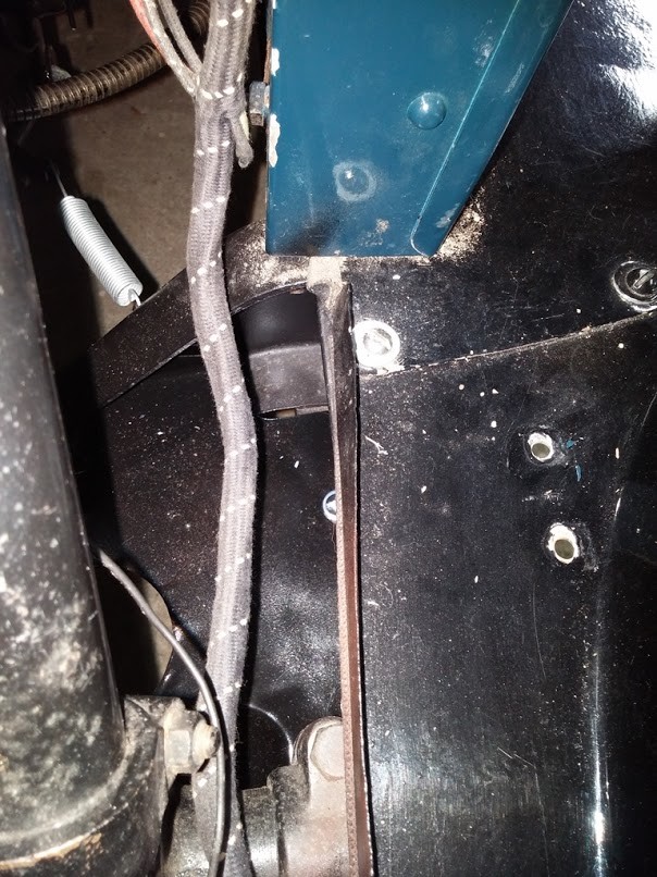
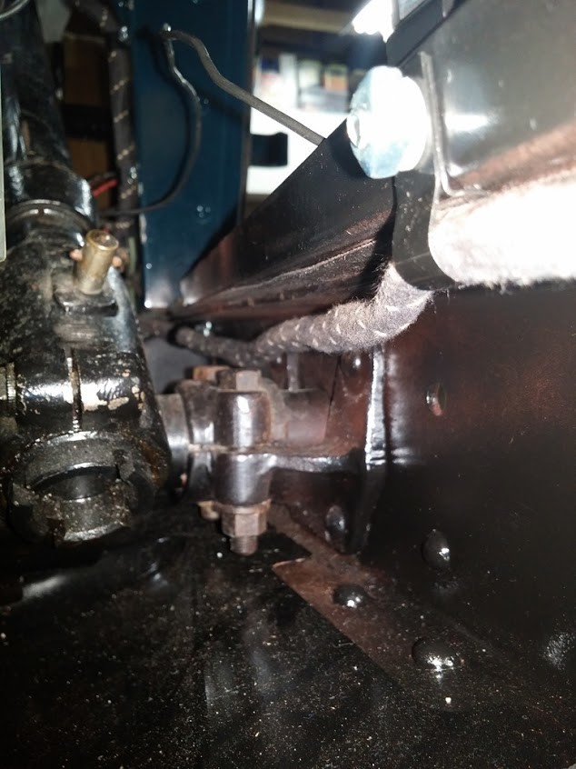
Screw/ washer on top rail near cross member, put clamp under top rail, This would be a TIGHT hard turn to secure the Wire Bundle into the Wire Clamp if I used this Screw, other two holes on right are outside frame rail.
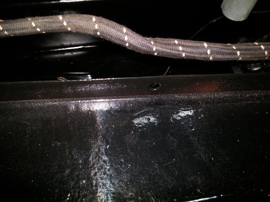
This is where the center Hood Bumper goes, also understand that a Wire Clamp goes here as well. Assume it mounts on the inside of the rail and Down to hold the bundle.
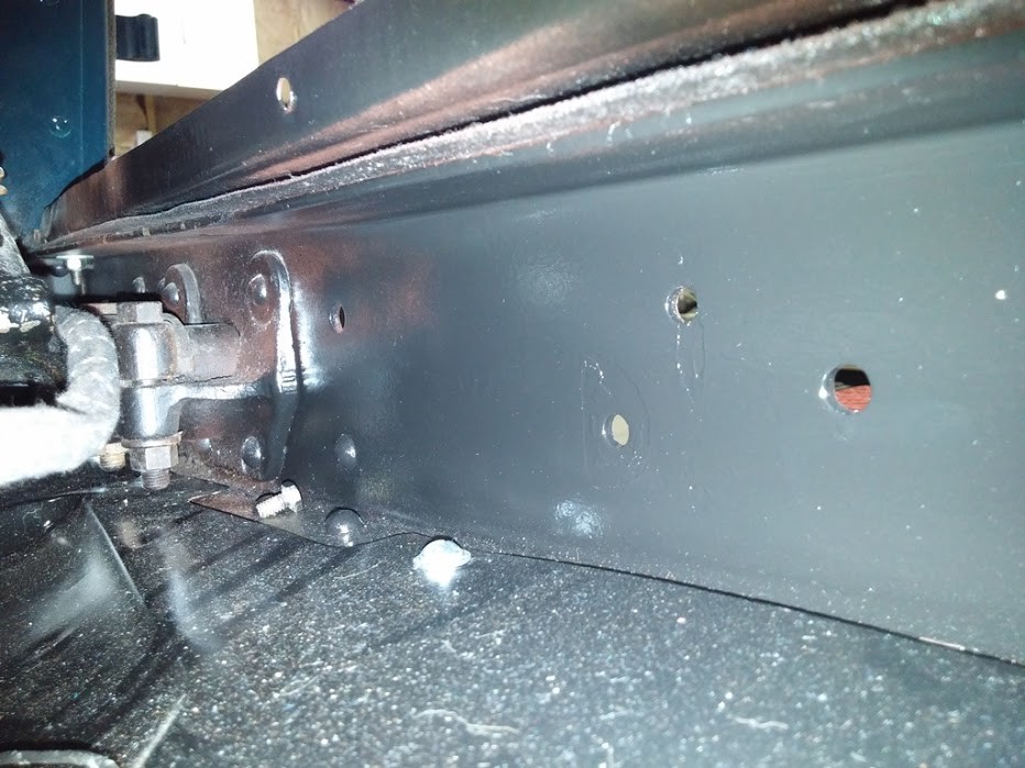
Can see the hole where center Hood Bumper Goes top center. not sure what the hole in frame rail near the steering box is for ? two of the three holes on the right hold the Horn (Back two holds), the other hole farthest right ?? not a clue.
Wire Clamps across the front of the Cross Frame Rail
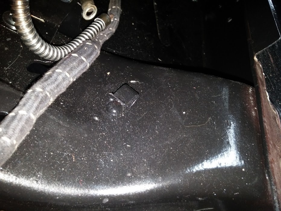
this clamp is on the right where the wire clamp comes down the frame rail
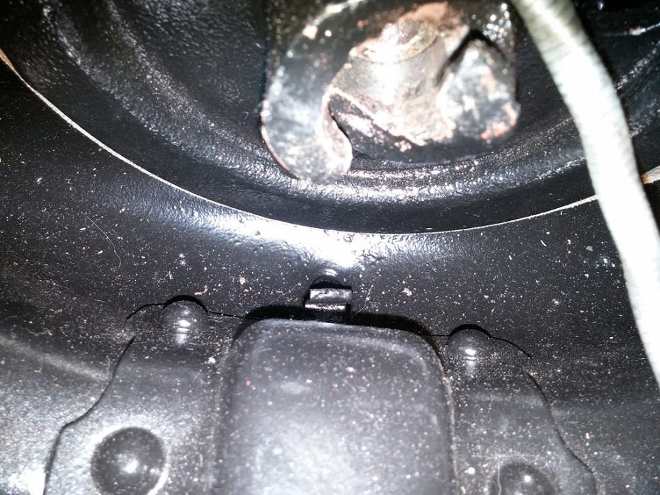
Wire clamp in cross rail right under Crankshaft Pulley
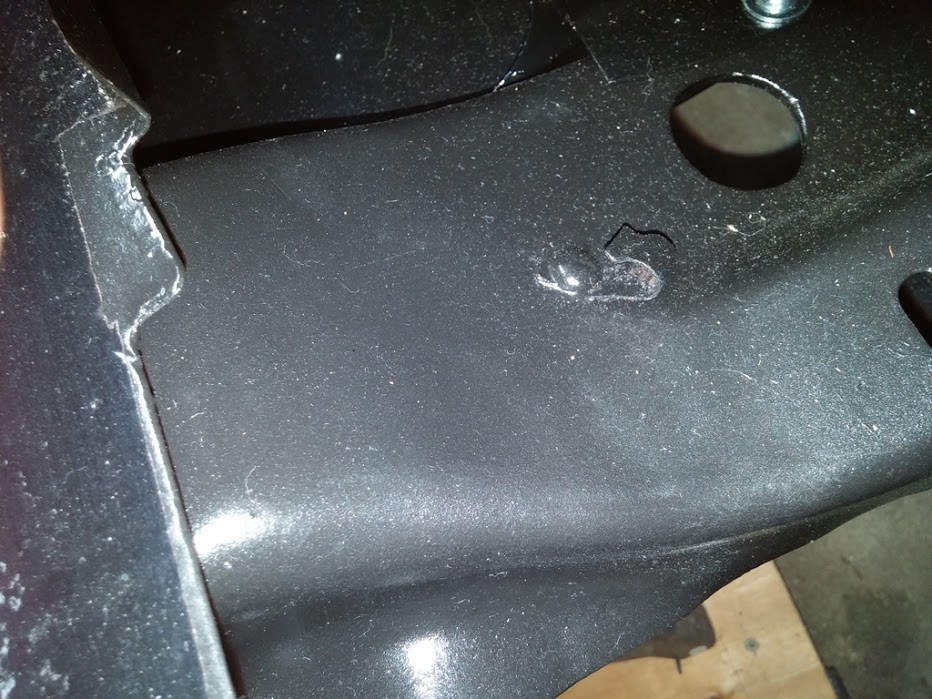
Looks like I need a second clamp on the Bundle right after it comes through the floor board. I have one, but per the pict there is two. I need to add in the upper one. Then I need to add one more in to the unpainted screw (Screw 1).
I have TFS #GR-237, which has a Wire Clamp, that goes under the frame rail. so this would be support number two.
Then it looks like there is a clamp in this photo as well this is where the bundle breaks off to the generator and the lights. but it looks like it is actually clamped onto the end of the metal armor cable vs the actual wire bundle.
10-31-2017
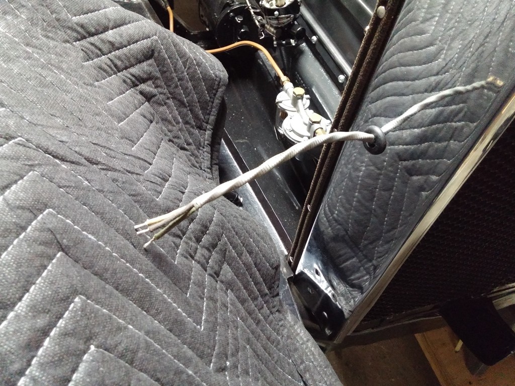
Wiring Down the Cowl Wall and in the Groove to pass under the Floor Board
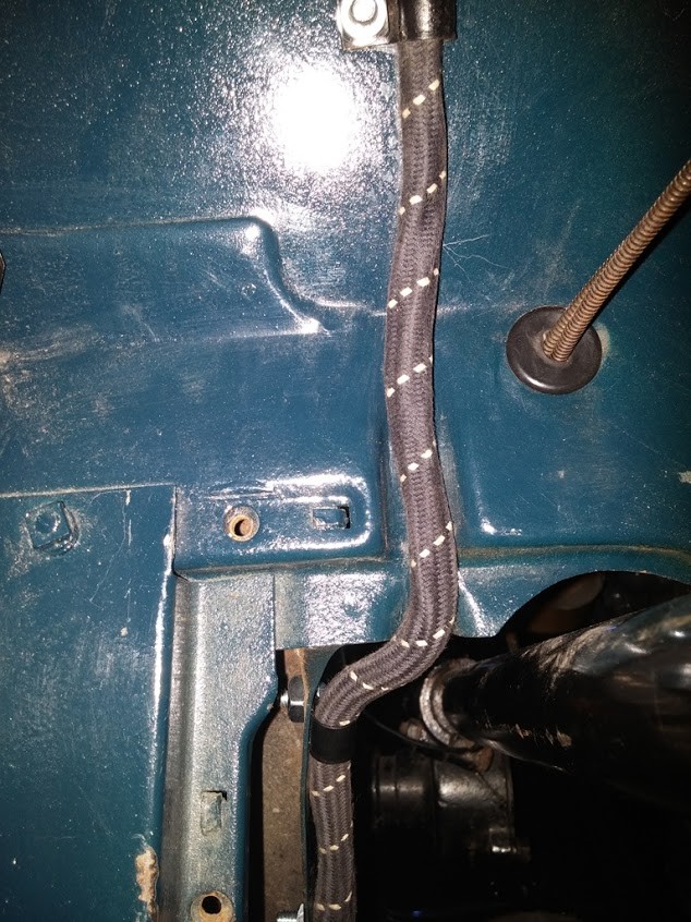
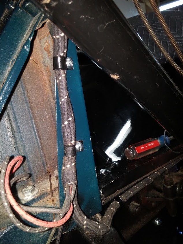
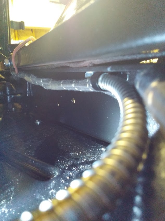
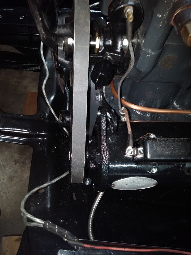
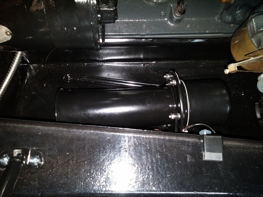
Got My Horn Mounted and Wired up
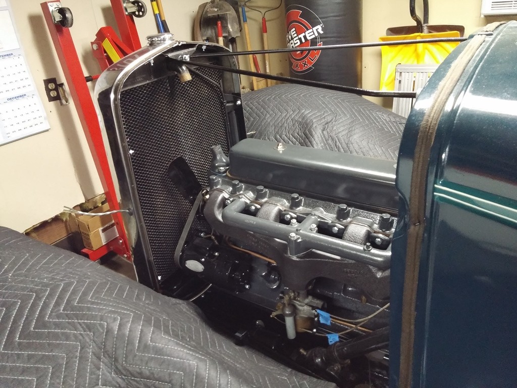
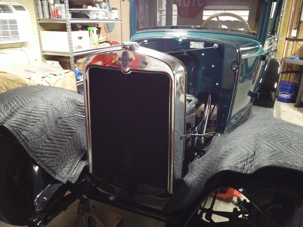
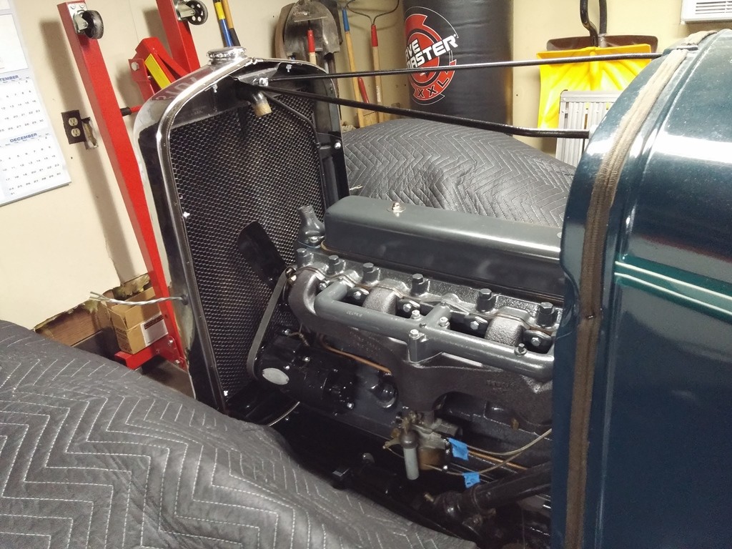
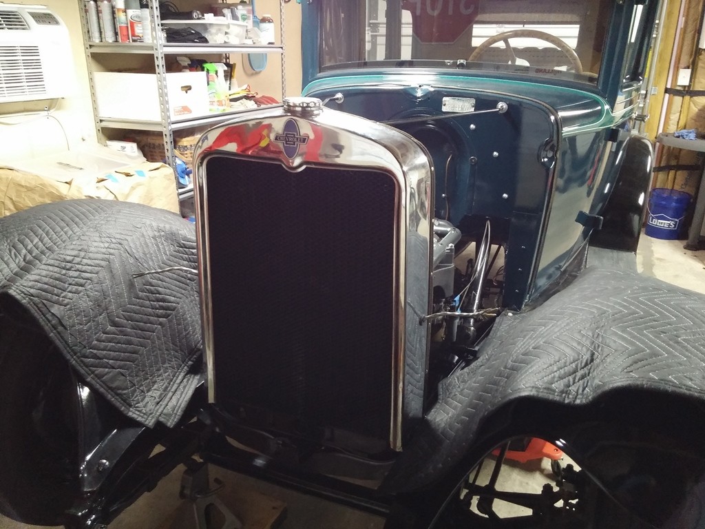
Finally got all my wiring done and horn mounted so next step was to install the radiator. I Used the TFS Kit FS-511.
Install was easy and i aligned and ensured that it was plum and square. Also installed the Support Brace. NO HOOD at this time, I will go back and install the hood once i get it running and all tuned up. Lots of hassle going back and forth side to side with the hood on.
11-3-2017
Need to finish up on the Drivetrain, Hoses, Clamps, Electrolock. Exhaust strip, prime & paint high heat, install and secure. Double check brakes, front, rear, new trunions, and reset. repair rear spare tire carrier, strip, prime, paint, install. Electrical, chase all wires, secure, possible turn signal routing and lighting, rebuild brake light housing and guts. install headlight bar, stanchions, wire it all up. floor boards and rubber mat. then sure i am missing or forgetting something, once together will fire it up and tune it in, then a few test runs, and work up to duration. want to have it ready for out local spring square car tour. lots to do and NO time to do it.
11-6-2017
Finally got all my wiring done and horn mounted so next step was to install the radiator. I Used the TFS Kit FS-511.
Install was easy and i aligned and ensured that it was plum and square. Also installed the Support Brace. NO HOOD at this time, I will go back and install the hood once i get it running and all tuned up. Lots of hassle going back and forth side to side with the hood on.
orking on putting my Electrolock Back in my 1929. Got the Tech Sheet with all the parts, order of Assembly and instructions.
Questions i Have:
1- Does Item 6, which looks to be a split lock washer go inside the Ferrule number 5 or does it sit up against the ferrule.
2- Item 7 Slip Fiber Bushing, looks like it goes through the wall of the distributor to isolate the electrolock shaft from grounding out. does it go into the ferrule end as well or does it but up against the split washer from question 1 ?
I have all the pieces to assemble but does not seem to go all back together tightly. right now Item 7 Slip Fiber Bushing sits against teh Ferrule and slides in through the Distributor. I align the pin on the ferrule to the hole in the distributor.
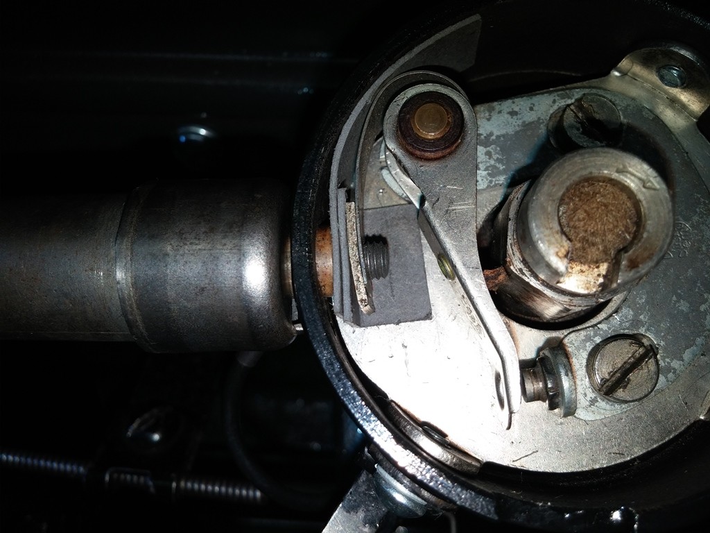

This is what i took apart, I added in the second lock washer Item 6. The Spacing is where the Condenser, Distributor, and Points go.
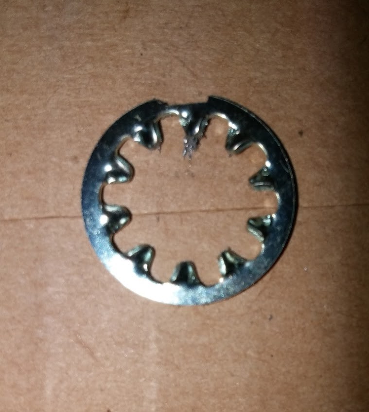
I took an 3/8 internal tooth washer and used my flat file and put a notch in the one side. this is to accommodate the pin in the ferrule. i went this route because it was THIN and looks like the original ones i seen in picts. The standard 3/8 split washer would need to be ground/ thinned some.
Ok here is a step by step picture by picture of my attempt to reassemble the electrolock in my 1929... Hopefully guys on here with knowledge and experience will correct me on anything i have done wrong (I hope)
This is where I started, here is the Threaded end of the Electrolock that goes into the Distributor. I Cleaned up and chased the threads.
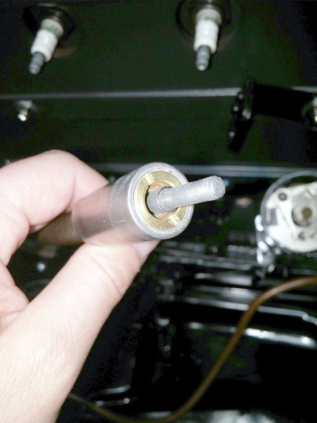
Took and placed the Fiber Washer (No Item Number, so Item 0) up to the face as far as it would go.
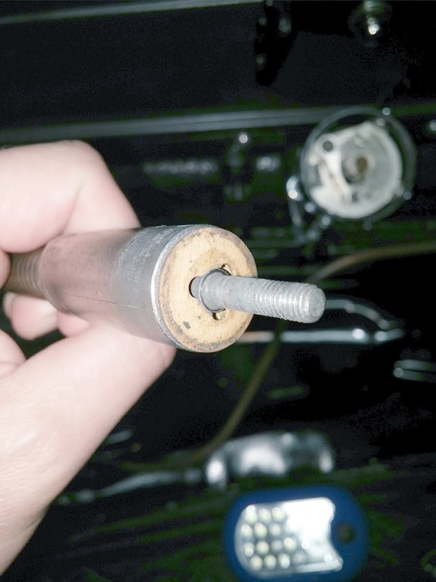
Then placed on the Steel Spiral Lock Washer (Item 1) all the way to the Serrated Hole Fiber Washer.
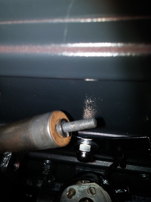
Next placed the Fiber Bushing (Item 7) in the End of the Ferrule (Item 5), and ensured that it would install flush on the inside of the Distributor.
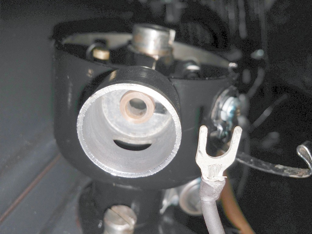
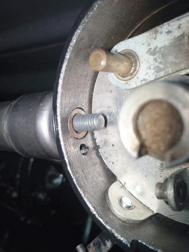
Install the Fiber Washer (Item 4) into the Ferrule (Item 5) and make sure it is flush against face of Ferrule. should also center up around the Fiber Bushing (Item 7) Previously installed.

Placed the Flat Steel Washer (Item 3) in the Ferrule (Item 5) centered and up against the Fiber Washer (Item 4). when trying to do this i found it a LOT easier to sit the Flat Steel Washer (Item 3) on the center of the Threads of the Electrock Cable.
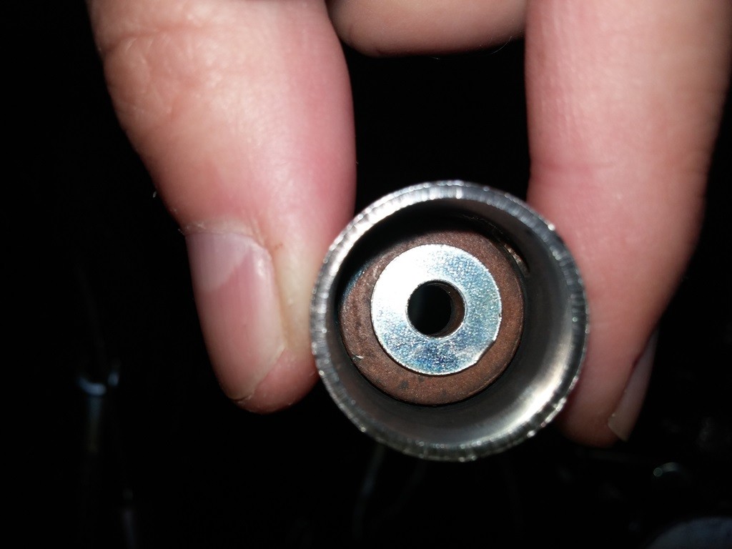
Slowly and gently slide on the Ferrule Assembly from above onto the end of the Electrolock Shaft, DO NOT slide it all the way on, just barely onto the threads. so you can look in the slot of the ferrule (Item 5) and see the Steel Washer (Item 4) to the right, and the Split Lock Washer (Item 1) to the left. You will have to slide the condenser connection in between if you used a Split/ Fork Type Connector, if using the Ring type, you will slide that on the Electrolock Shaft BEFORE sliding on the assembly from above.
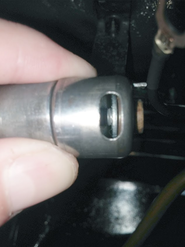
You can see the gap and Washers Clearly.
I then slid in the Condenser Wire Connector (Item 2), this HAS to go in between the 2 Steel Washers, Item 1 and Item 3.

No matter what Style Connector you use on the Condenser, this is what it should look like so far.
I then slid on the Custom Made Washer (Item 6) this is simply a 3/8 Internal Tooth Washer that I used a file to made a slot for the Ferrule Pin to go. Washer (Item 6) Installed Notice the Pin fits in the slot I made on the washer.
This Assembly now should go into the Distributor, made sure the Pins is aligned with the slot in the Distributor Wall. The Fiber Bushing (Item 7) should go through the hole and mount flush, the Electrolock Shaft should go all the way through.
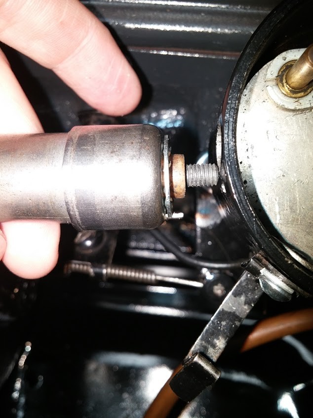
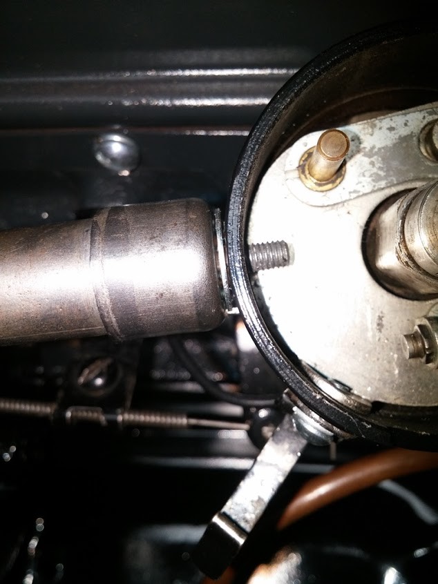
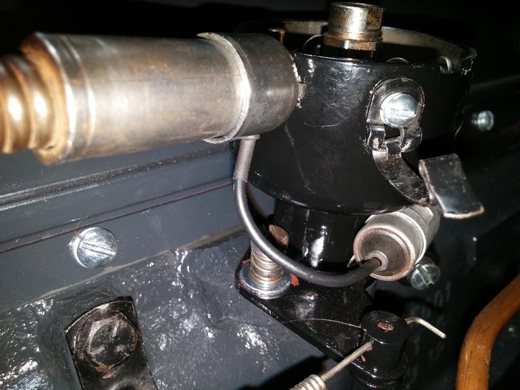
Now install the Fiber washer (Item 8) I made it out of Rubber Gasket Material, as it is NOT Conductive and easy to cut. This must cover the leg of the Points and keep it from touching the Distributor wall. make sure it is on all the way against the Distributor Wall.
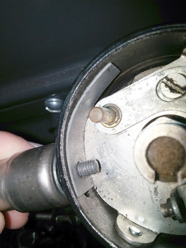
Next installed the "L" Shaped Fiber Gasket (Item 9) onto the shaft against Fiber Gasket (Item 8) with the leg down on on the Plate. This Gasket seems to keep the Nut and Washers from touch the plate and grounding out.
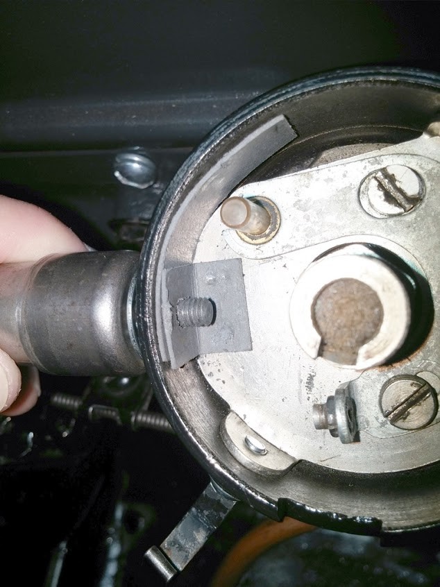
Then install the Steel Plate (Item 10), make sure you install so the curvature matches inside the the Distributor Wall. this goes up against the 2 Fiber Washers (Item 8) & (Item 9)
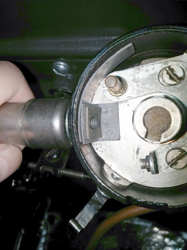
Now Install the Points (Item 11), make sure the Arm is against the Fiber Gasket (Item 8) and (Item 9).
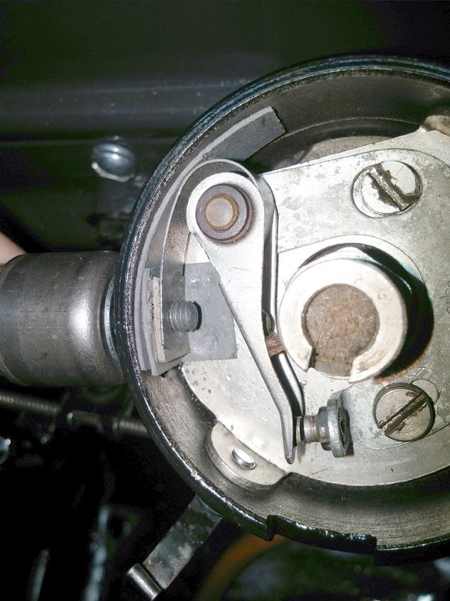
Install the final part, the Nut (Item 12) I have a standard #10 Nut, lot easy to get on and off and NO special Tools Required
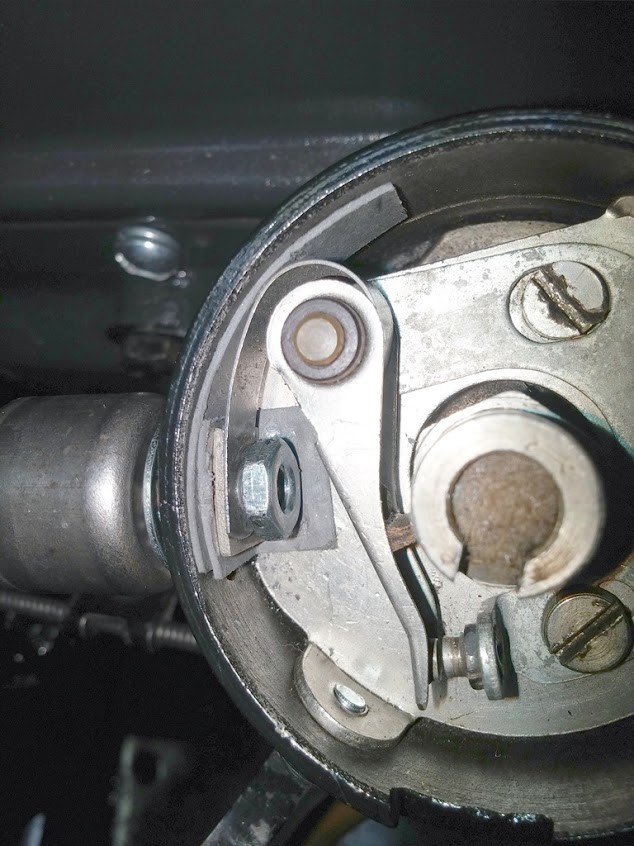
All left to do is tighten up the nut to secure the cable and parts in place. I tightened it up till snug, then a 1/4 turn to secure in place.
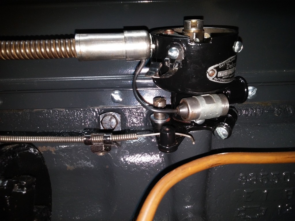
Let me know what i missed or messed up... thanks !!
11-20-2017
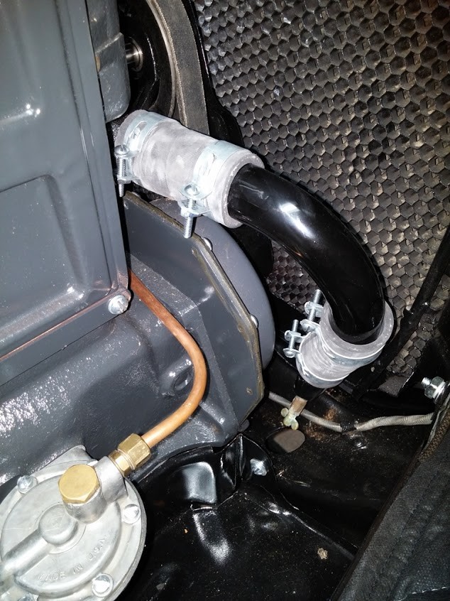
Installed my Hose, ended up getting a 36" piece of Dayton Wrapped Hose, looks great and is pliable. also got a New Elbow to be safe.
Cut it into lengths i measure out for each section.
Installed Some hose clamps that I got from TFS. looks like the old ones are different from the new ones i just received.
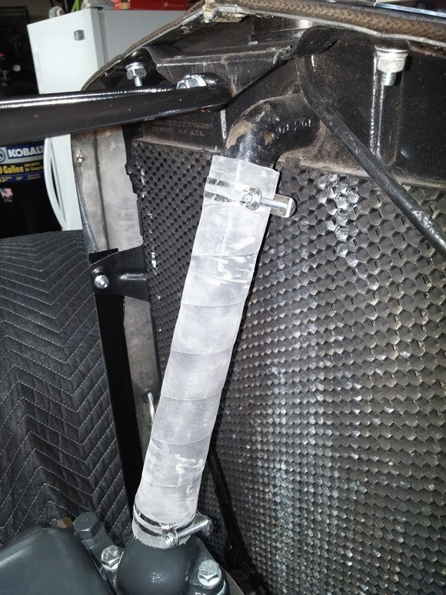
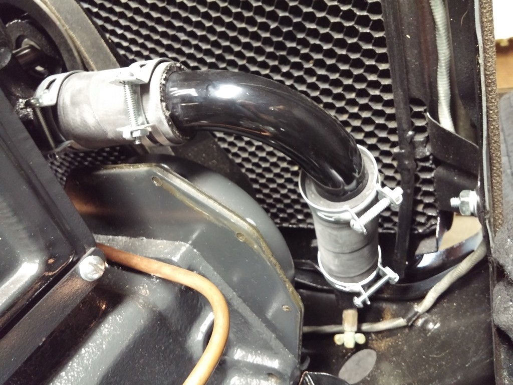
Clamps are NOT tightened yet
When installing my Hose and Clamps i noticed that the NEW ones I got from TFS are thinner than the older set i got.
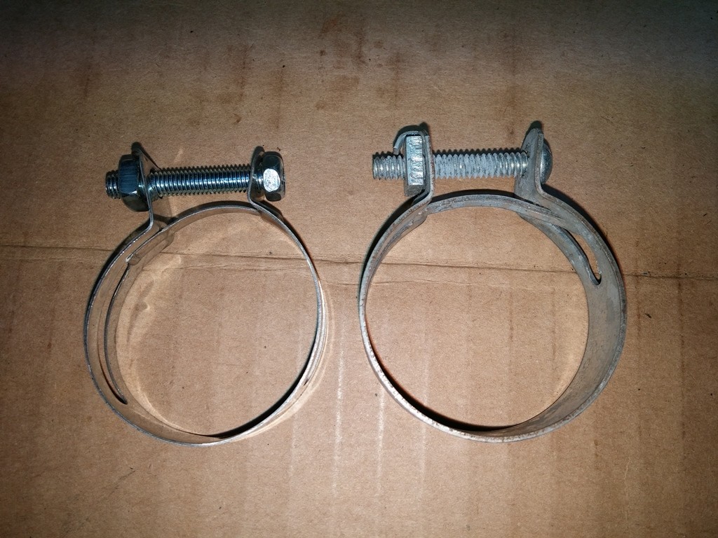
Also noticed that they have totally different hardware. The NEW set on the left. Phillips drive hex head screws on left, round head slotted drive on right.Both are 10-24
The set on the left is approx .022" Thick and very flimsy where as when i tighten them up on the hose they distort badly, not even wrenching them down, can easily flex and bend with my fingers. the set on the right is approx .040" thick and a lot more sturdy, i can wrench these down and they do not distort. also the set on left is more of a zinc plated material, whereas the one on the right is a galvanized looking material.
Few Picts Fastened In
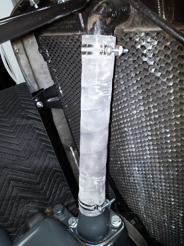
11-4-2017
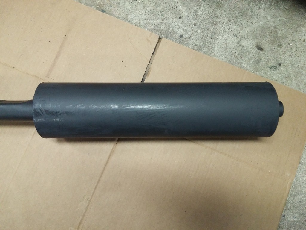
Figured I would work on getting the exhaust system cleaned up and ready to go in the car, since i am at that point. looks like the PO had a new exhaust system made / bought to replicate the original style.
I took some time to sand and clean up the surface rust and such. Then I put on a few coats of High Temp Primer Followed by a Few Coats of High Temp Exhaust Black Paint. looks a lot better than it did when it came off.
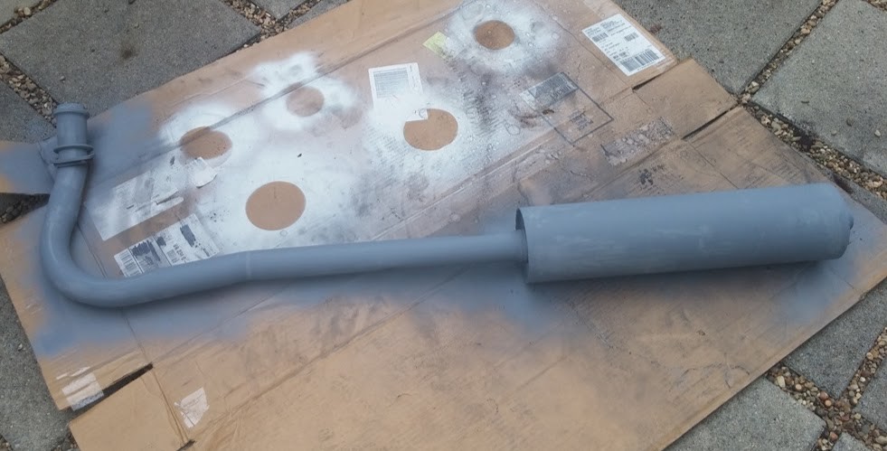
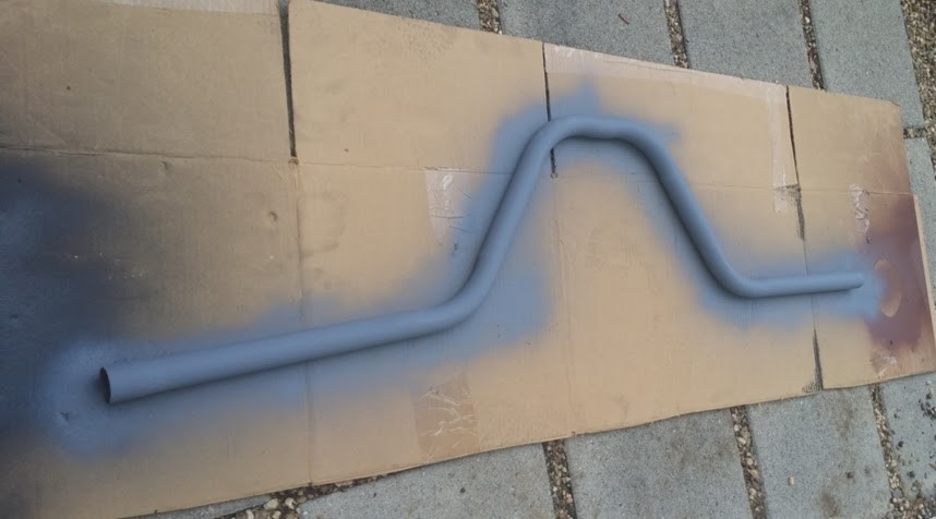
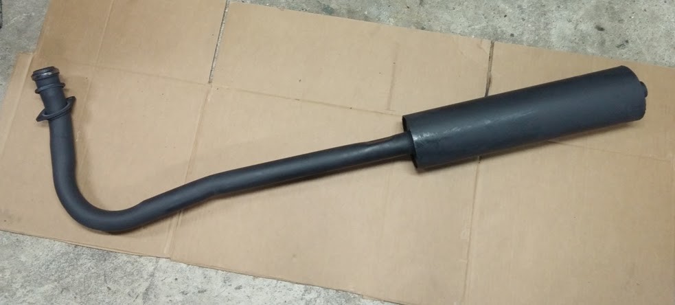
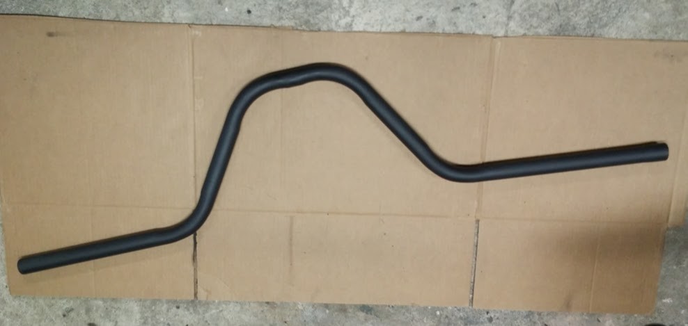
A few Close up of Muffler and other
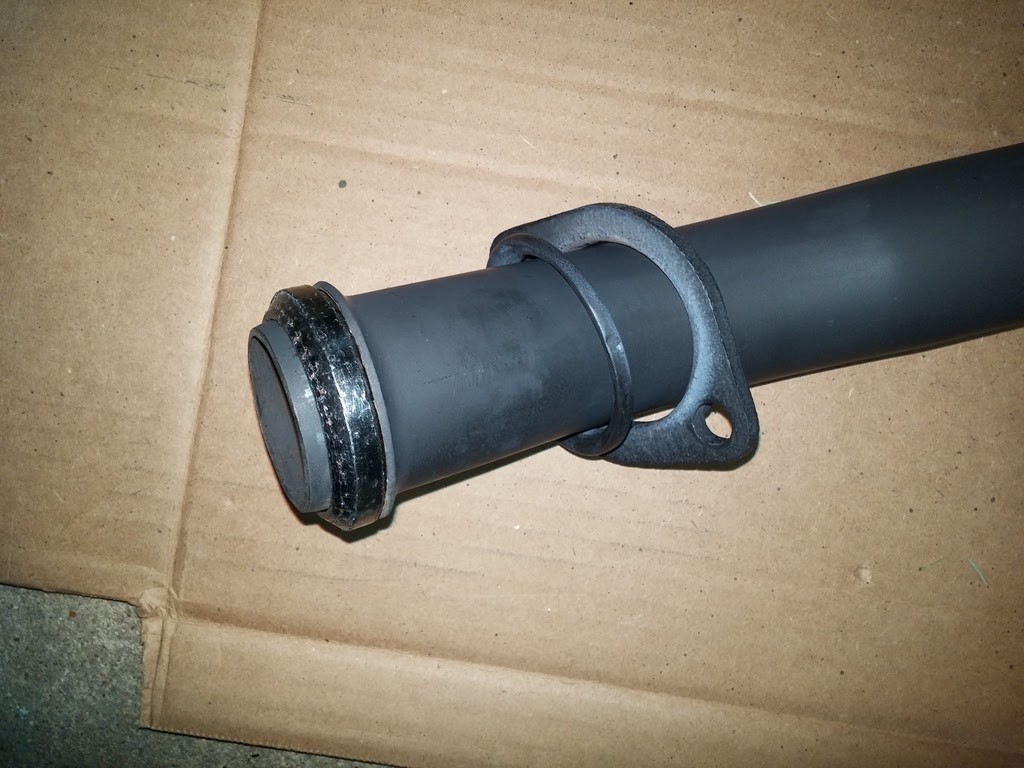
r and Paint to go back on.
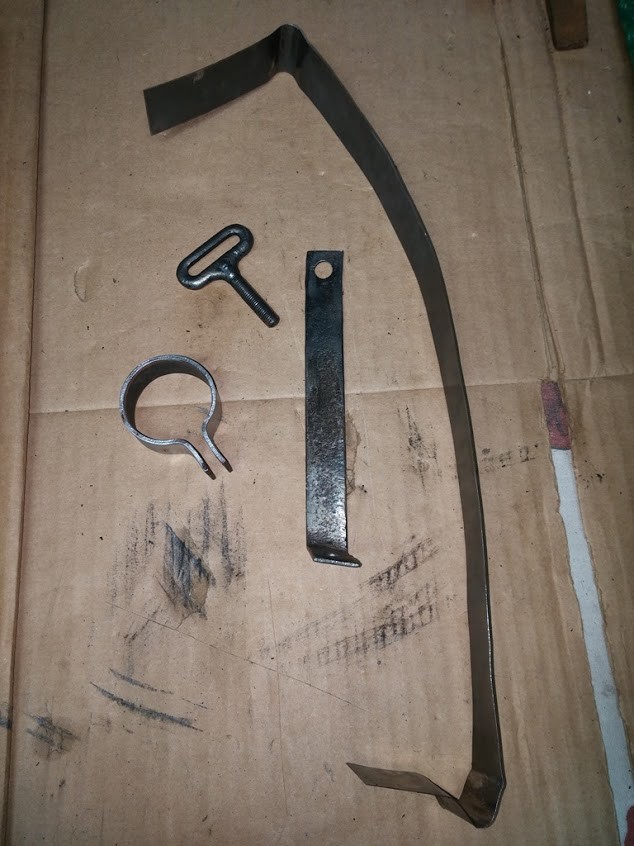
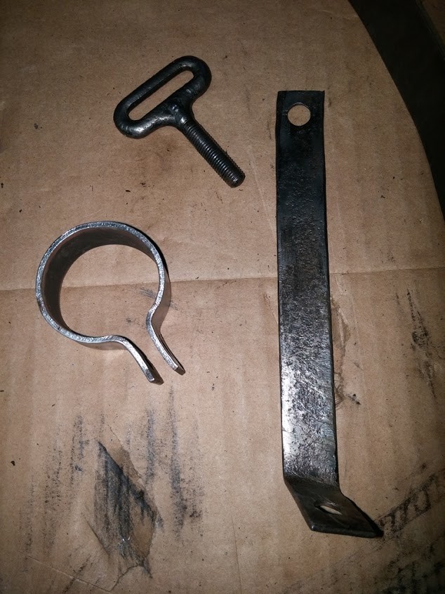
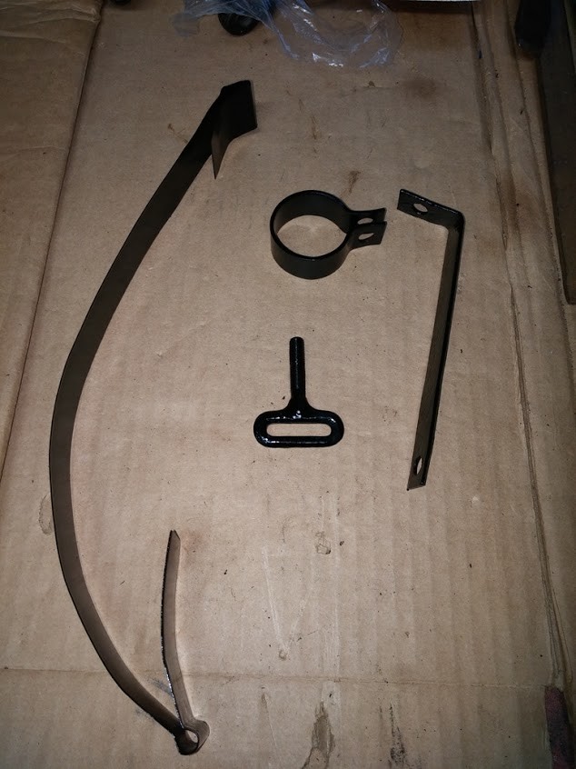
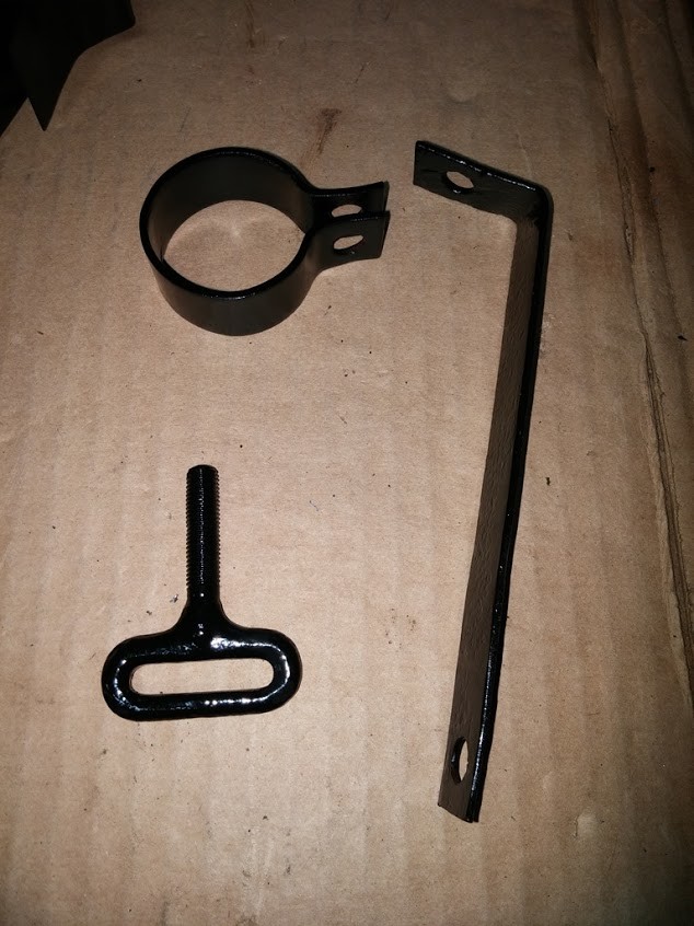
looking to see what actually holds on the 2 Chrome Strips on the Front Radiator Splash Apron. I have the Apron, need to massage and work it to fit properly on the front clip, it is a little mangled. Need to know how the 2 Chrome Strips are secured/ fastened to the Apron ?!? Looks like there should be some sort of Clip ?
I also procured a New Tunnel & Crank Hole Cover from TFS, so will test fit that on as well. once it is all straight and in order, will tear it down, have the strips replated, then strip, prime and paint the apron and tunnel.
Then Can put it all together and put it on the car.
I will post some pictures later to make sure I have all the correct parts for the Radiator Splash Apron for my 1929.
OK took some pictures of what I have on hand:
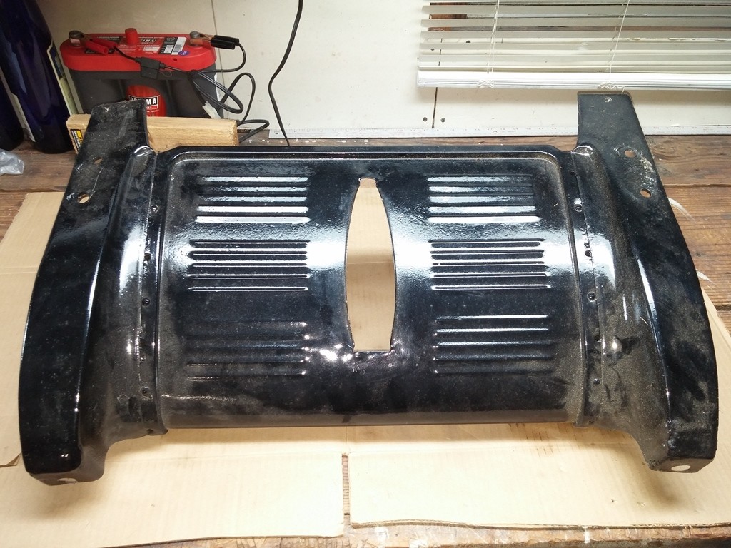
...Straight on shot from front
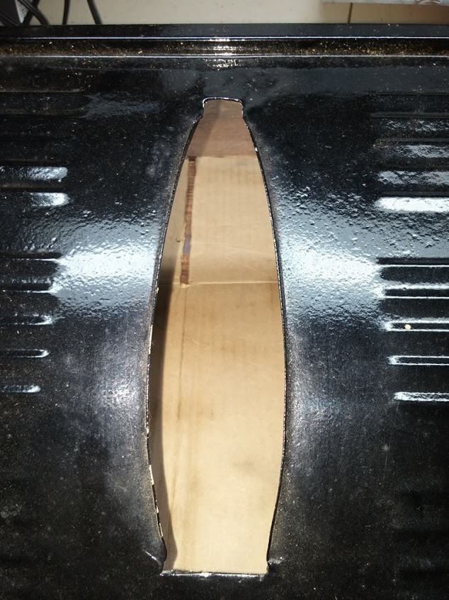
...Close up of Tunnel
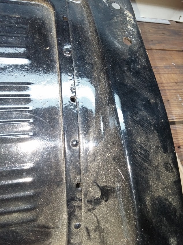
...Right Side Seam Close up, what goes in the Holes along seam they do not look inline with Rivets ??
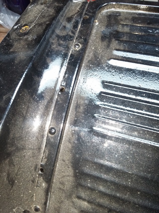
...Left Side Seam Close up, what goes in the Holes along seam they do not look inline with Rivets ??
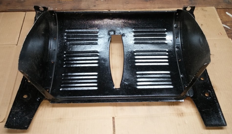
...Underside View
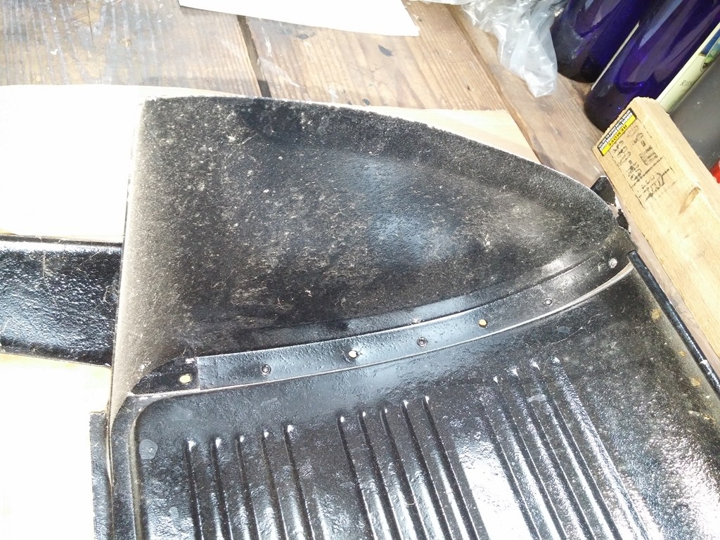
...Left UnderSide Close Up, can see the Holes and looks liek Square Nuts were in those palces based on recesses
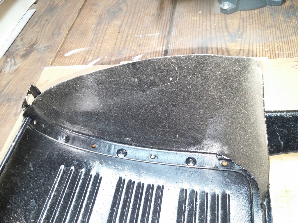
...Right UnderSide Close Up, can see the Holes and looks liek Square Nuts were in those palces based on recesses
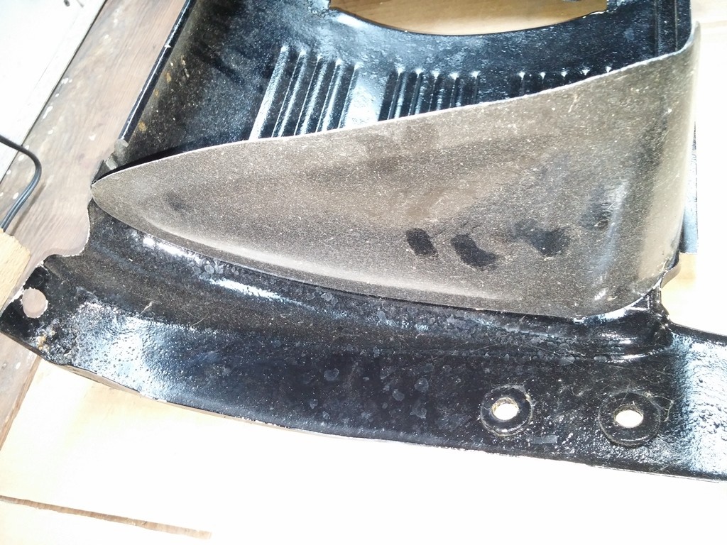
...Left UnderSide Outter Close Up, Do these washers belong on the mounting holes ??
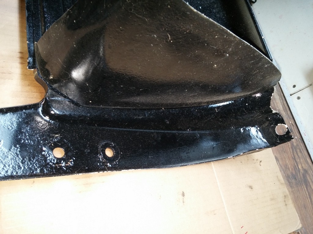
...Right UnderSide Outter Close Up, Do these washers belong on the mounting holes ??
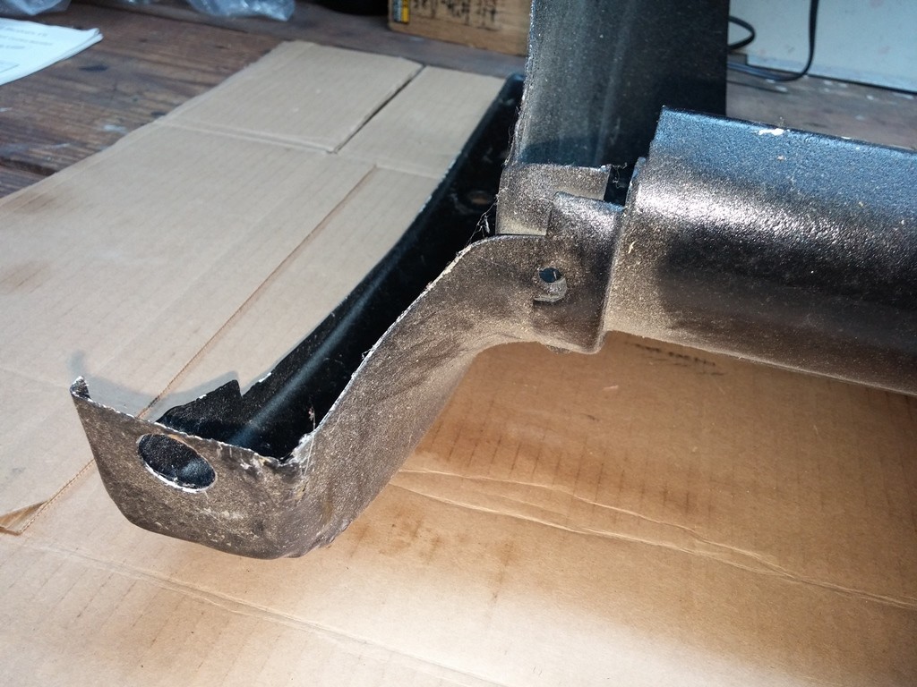
...Right front CLose Up, can see one of hte Questioned HOles Close Up.
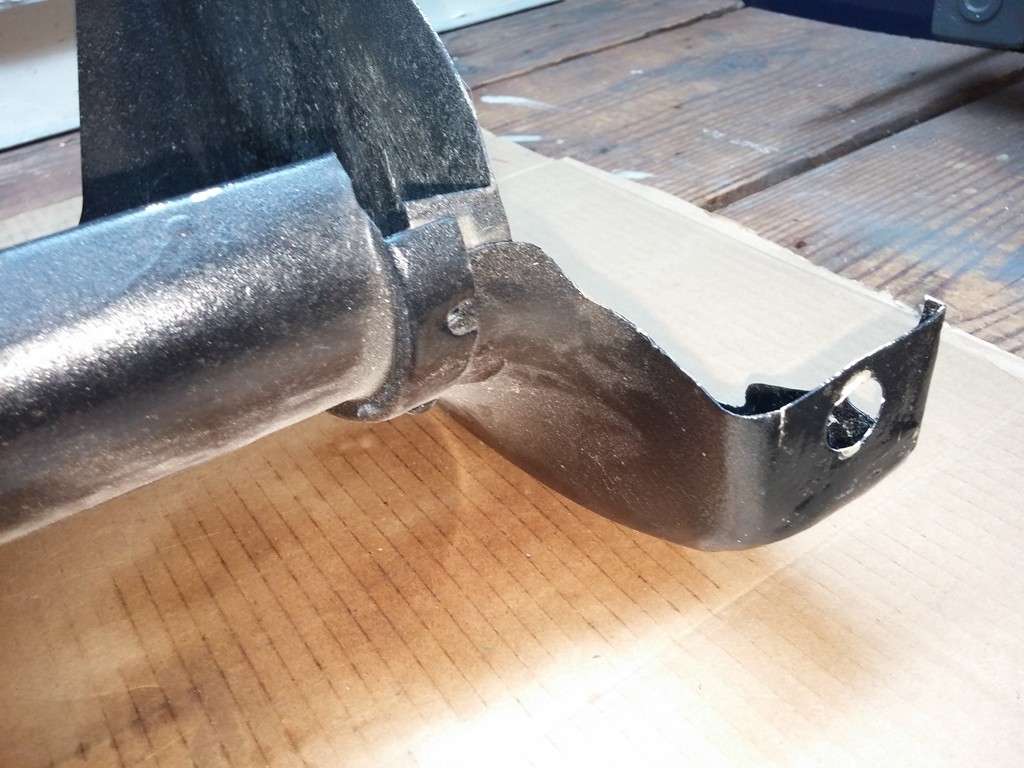
...Left front CLose Up, can see one of hte Questioned HOles Close Up.

...Straight on shot upside Down
Please take a look and confirm this is correct for my 1929 Chevrolet International 4 Door Sedan
Here are some pictures of my Strips:
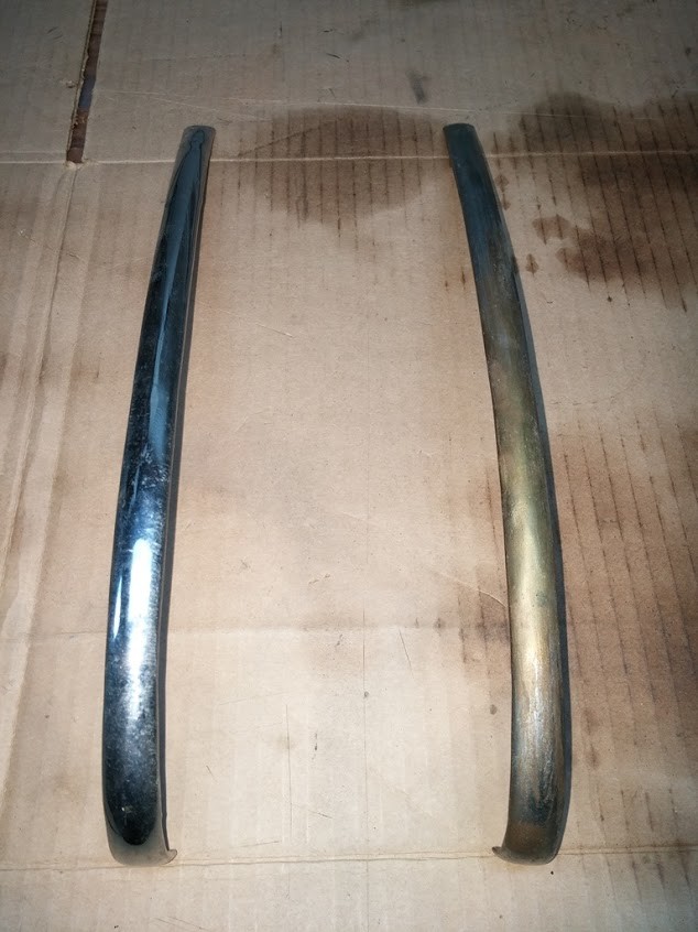
...Both Strips Top Down View
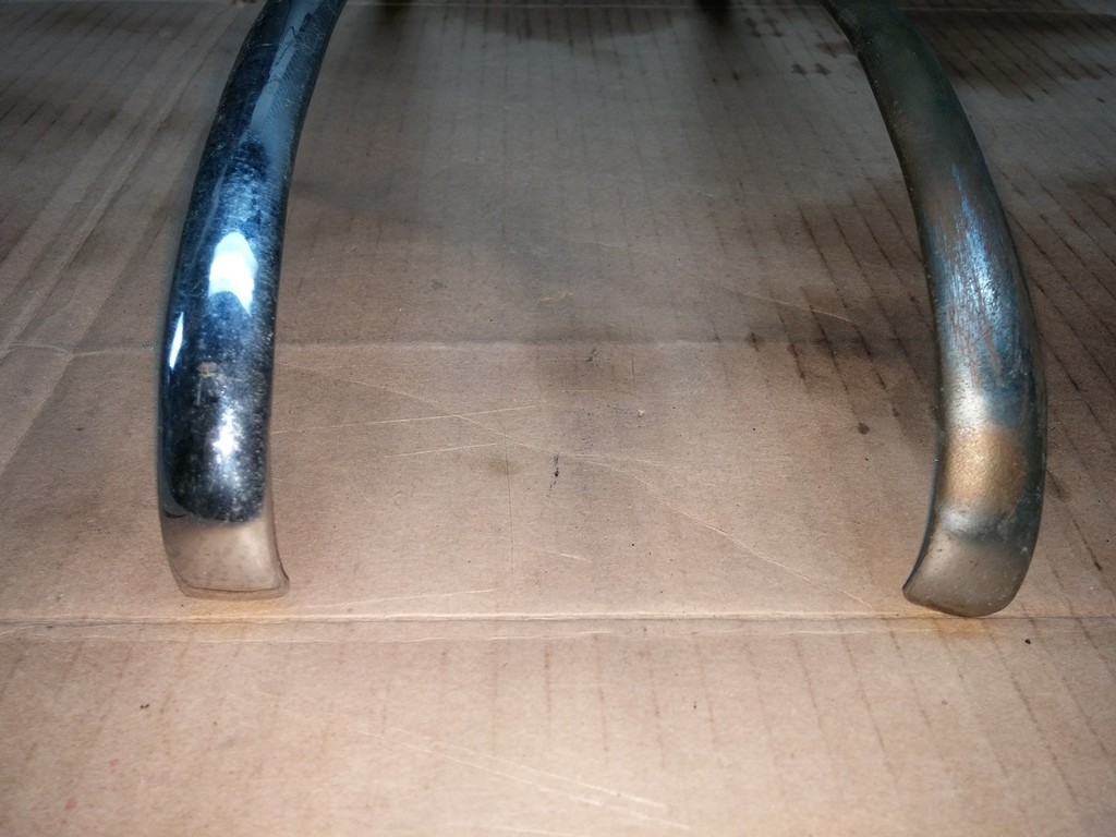
...Close Up Front End of Clips
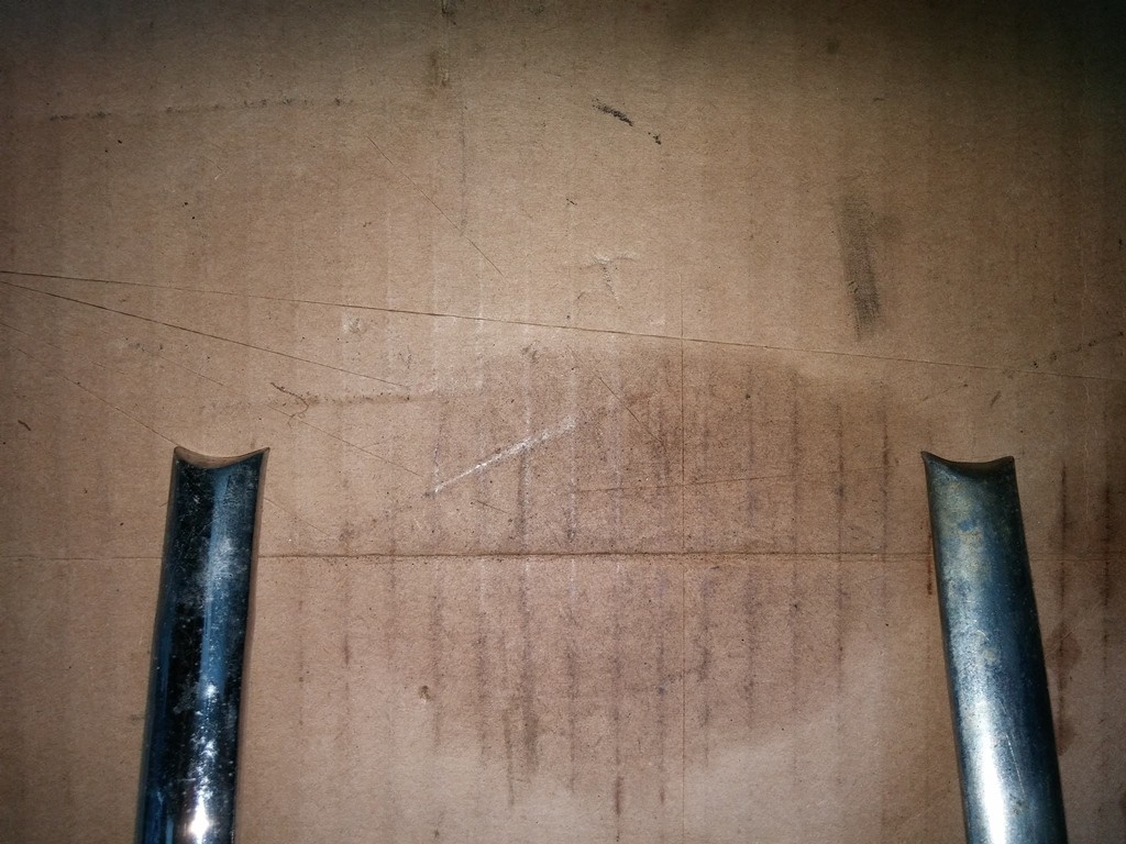
...Close Up Tail End of Clips
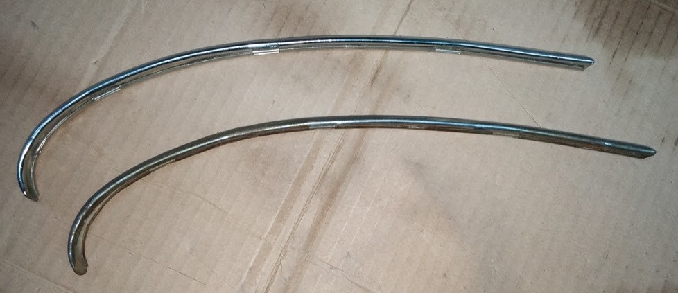
...Side View of Clips
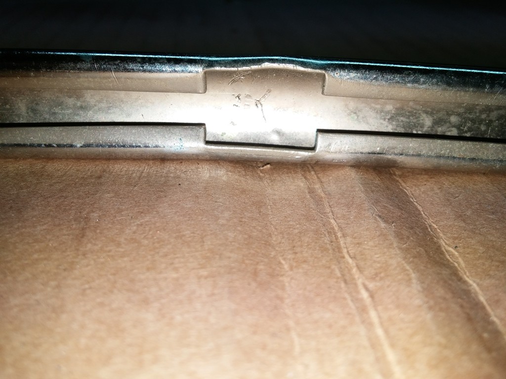
...Clip Mount on Underside of Strip
They look to be in good shape ?? just need replating and Clips
Great car !
Posted by Diggymart on 9/7/19 @ 3:48:57 PM