You must be logged in to rate content!
22 minute(s) of a 636 minute read
3-22-2017
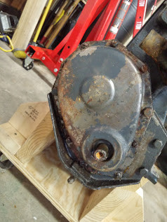
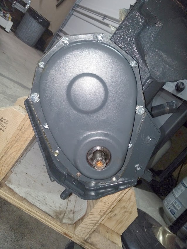
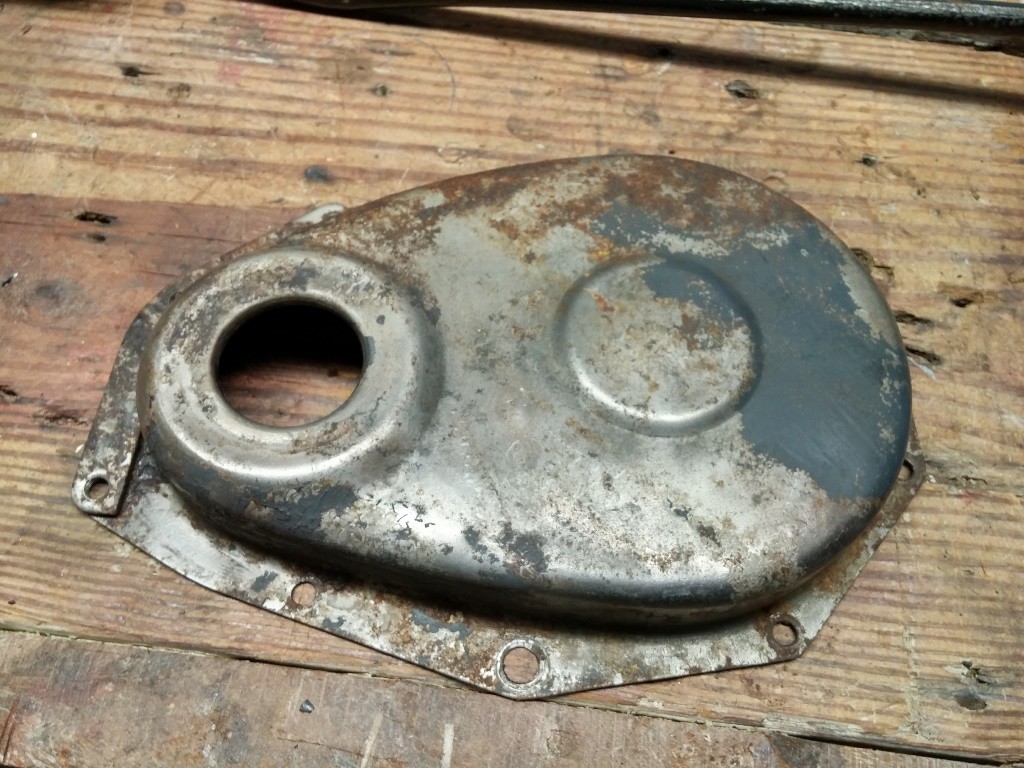
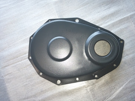
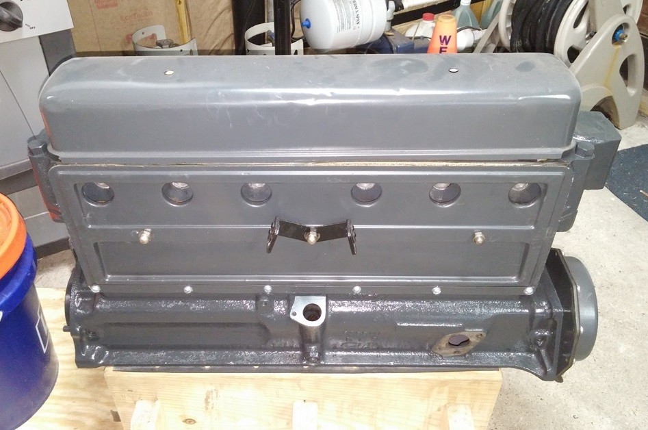
installed my redone crankcase cover last night. installed with new hardware and gasket. i used a lil Permatex No 2 on both sides to be safe and sure a good seal.
1929 Engine Front View Crankcase Cover BEFORE
1929 Engine Front View Crankcase Cover AFTER
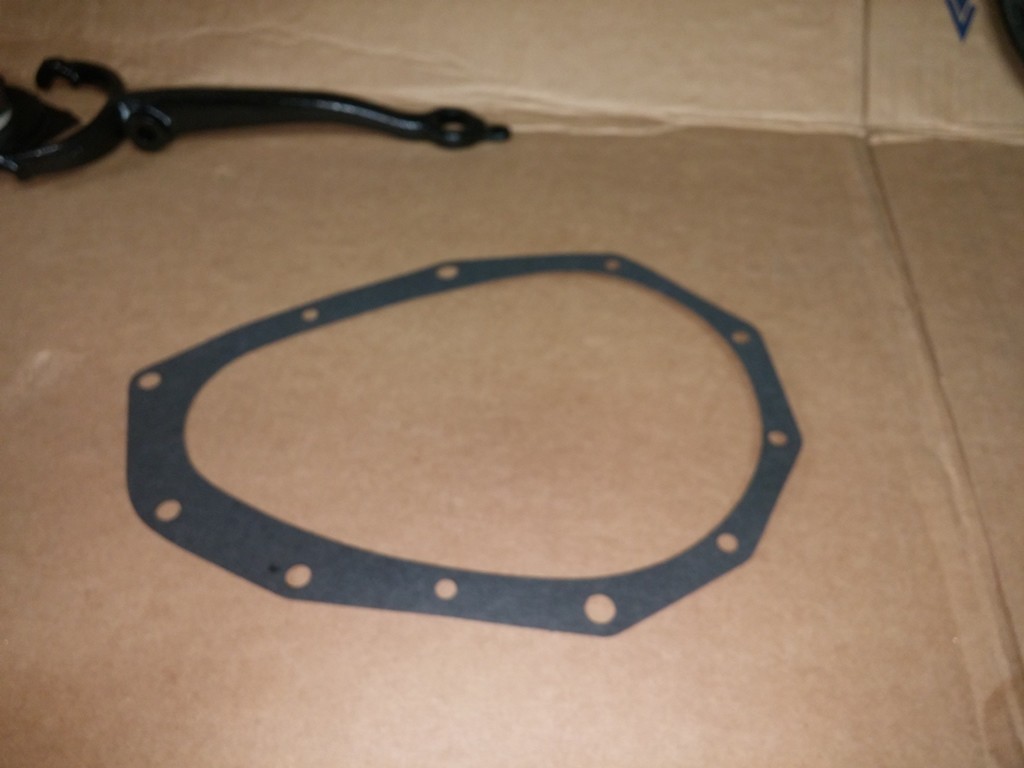
Few Picts of Process
Cover Gasket
3-24-2017
working on putting my 1929 Engine back together, i removed all the old tappets and replaced them with a new set from C&P Automotive (Billy Possum) ordered all the goodies including new gaskets for the Push Rod Cover.
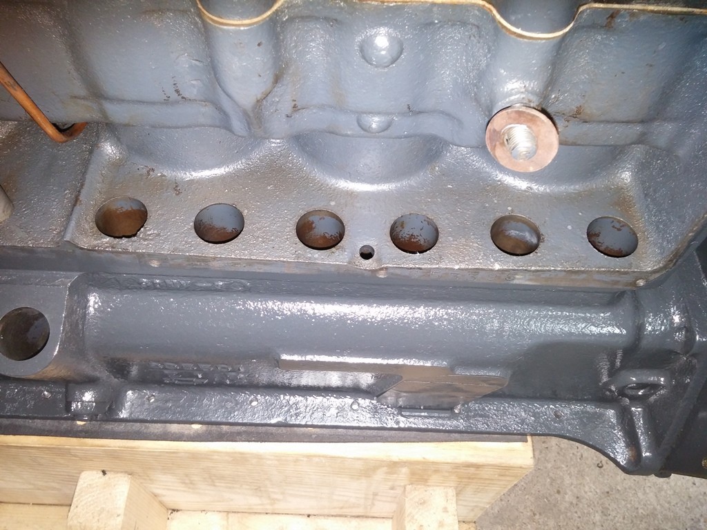
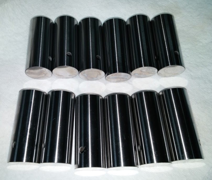
they were cleaned as per included instructions, then i applied a coat of 50/50 motor oil & STP to help them slide into place as well as preserve them until the engine is fired back up and libricated via oil.
Looking down into a NEW Tappet
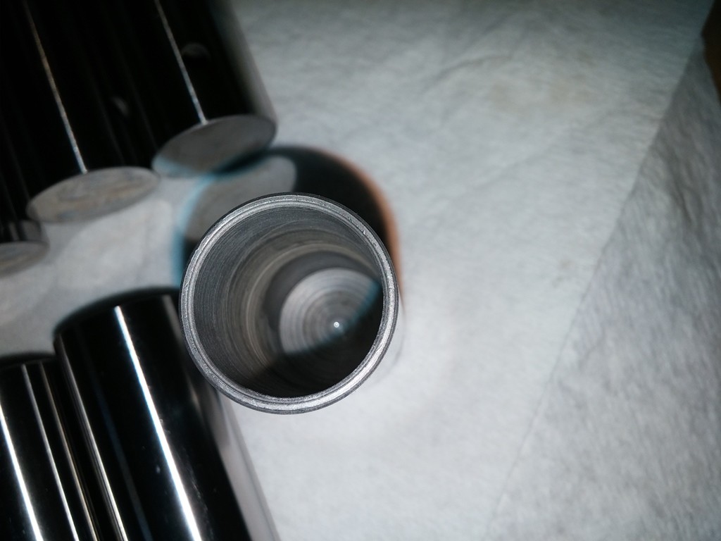
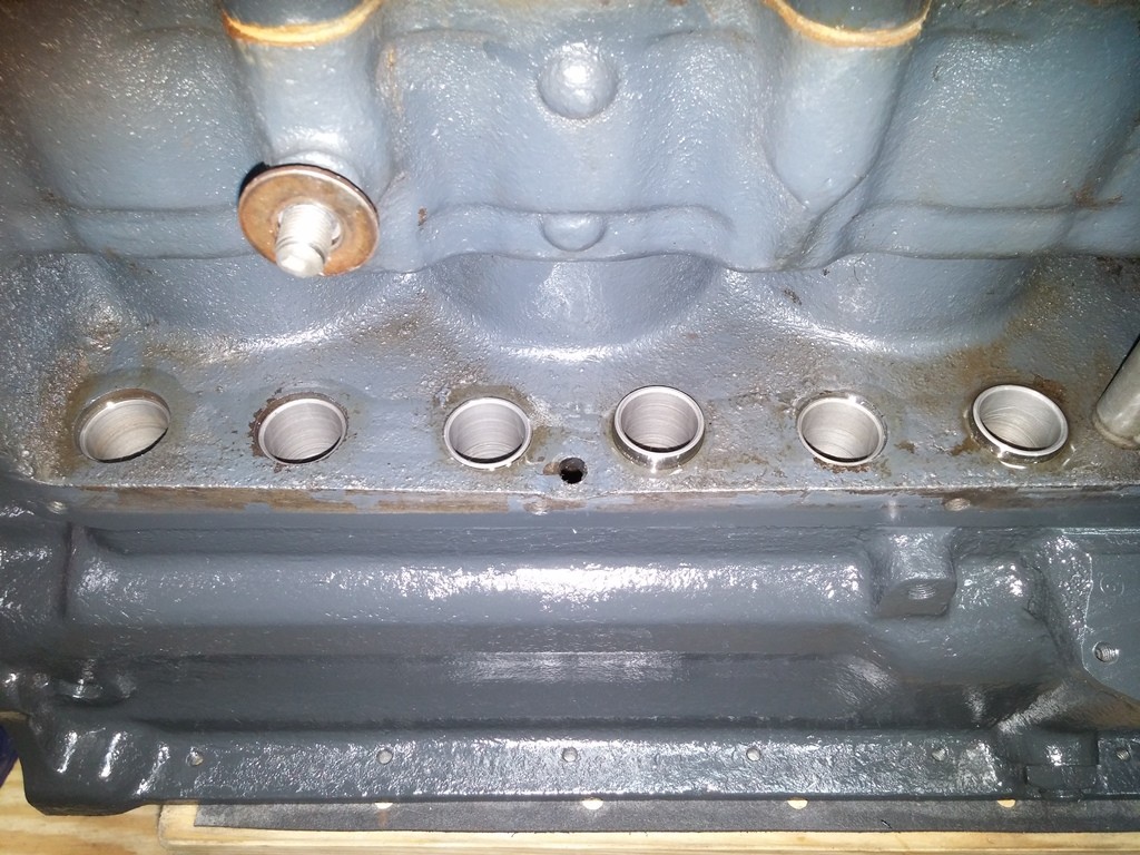
The New tappets installed smoothly without any hassle or resistance.
New Tappets Installed 1-3

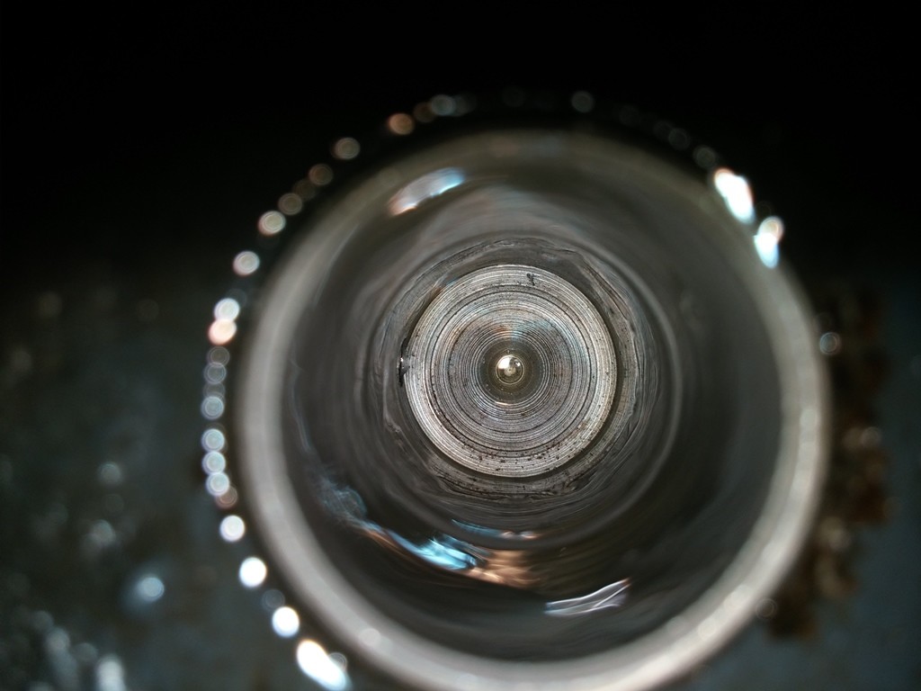
Looking down into NEW Tappet Installed and coated
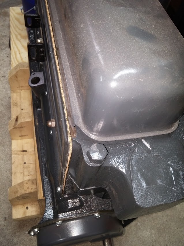
The Gasket kit i Acquired from an Estate Sale actually has CORK Gasket for the Push Rod Cover, Valve Cover, and the Oil Pan !!
I installed a thin coat of Permatex No 2 to the Push Rod Cover, installed the Gasket and lined it up, then a thin coat of Permatex on the Gasket and Installed the Cover to the Engine, aligned it and Secure it in place with hardware.
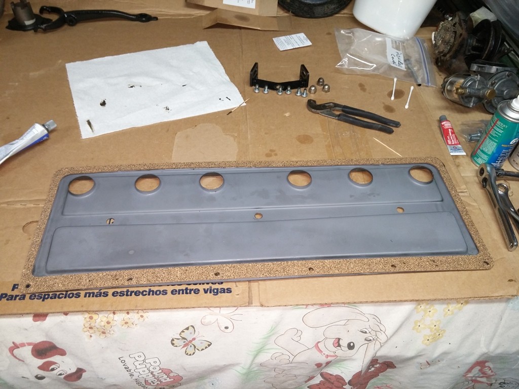
Thin Coat of Permatex No 2 w/ Cork Gasket Installed
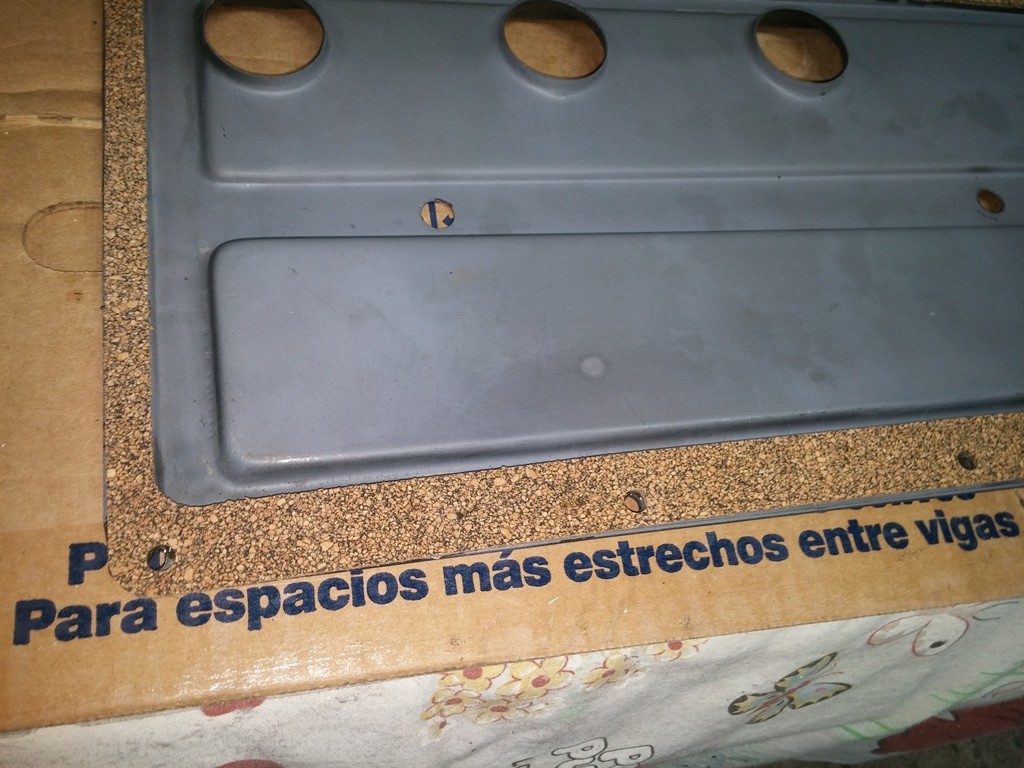
Cover Installed and Secured to Engine Side
5-17-2017
Installing the Throwout Bearing into the Clutch Fork, there is a Clutch Fork Spring that goes in and Holds the Bearing in place and allows it to rotate to stay flat against the Clutch Throwout Bearing Sleeve.
I bought NEW springs from TFS and this is what they look like installed.
They do not sit flush or go all the way in
Spring Install Top
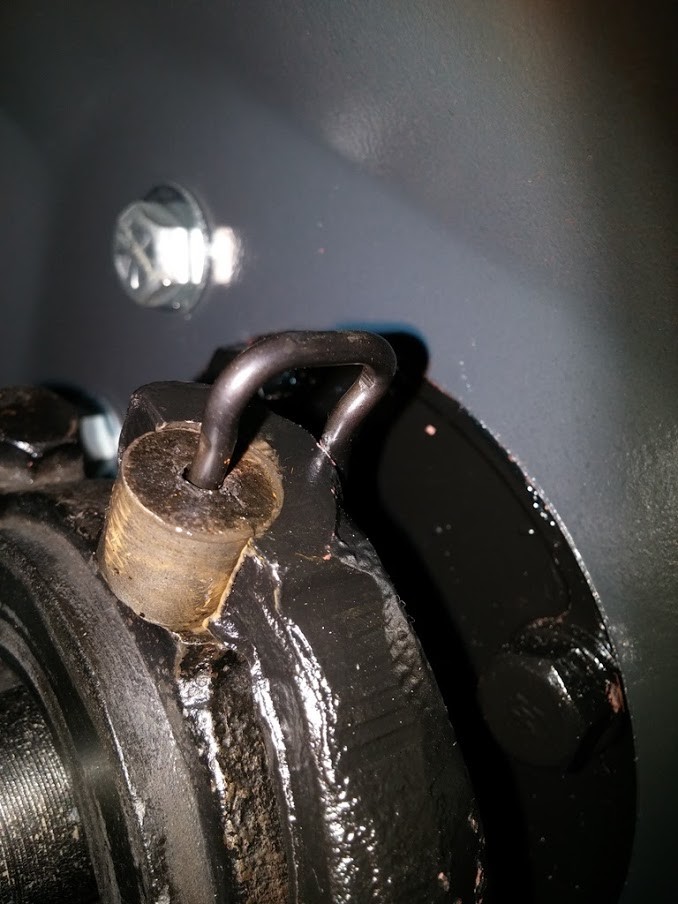
Notice the recess looks, like pin should sit in to stay, pin is in far as it will go
Spring Install Side 1
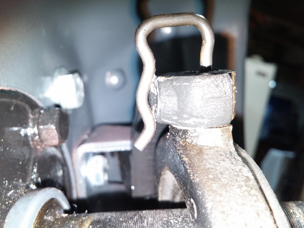
another view of spring
Spring Install Side 2
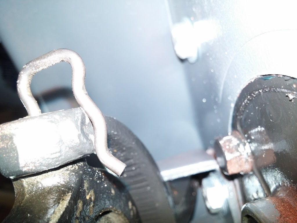
If i pull the spring out so the first bulge sits in the recess on the fork. it feels sloppy like the spring will just pop out. NOT securely seated.
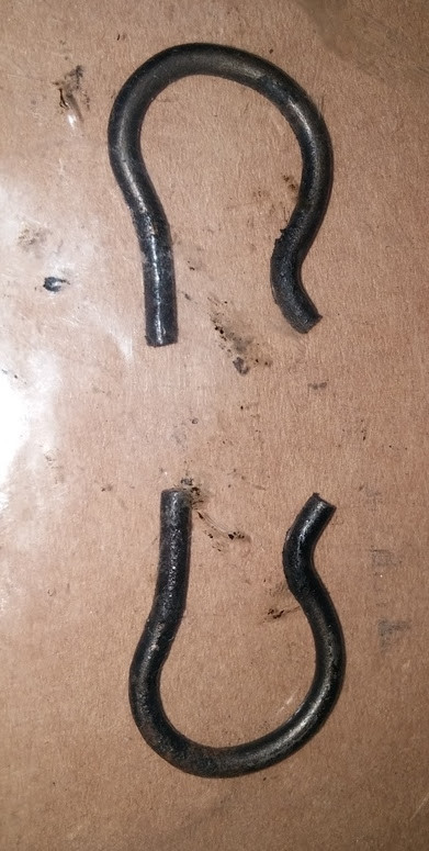
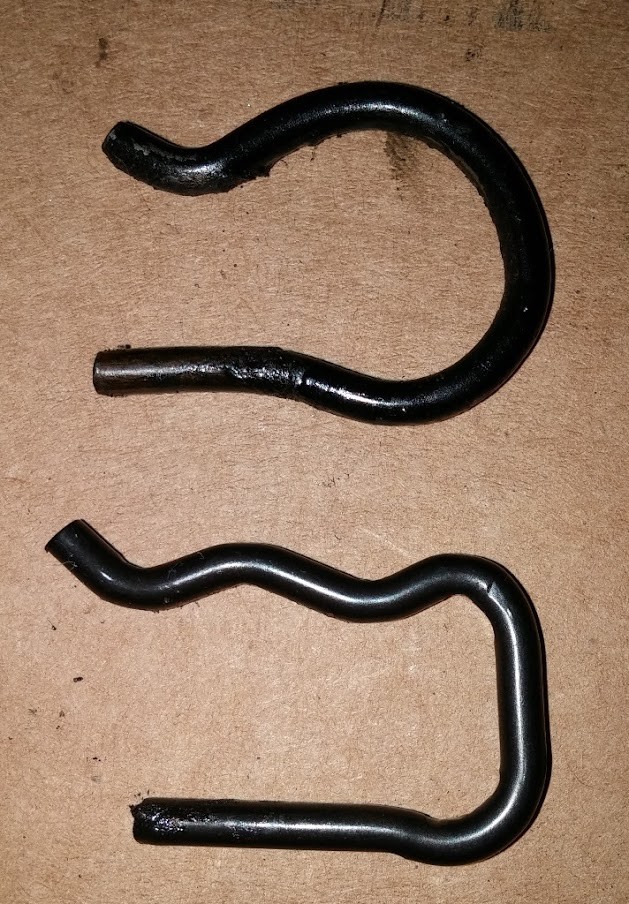
notice the shape of the original spring.
Here is the Original Spring (TOP) vs the NEW Spring (Bottom) Spring Comparison
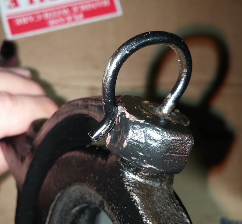
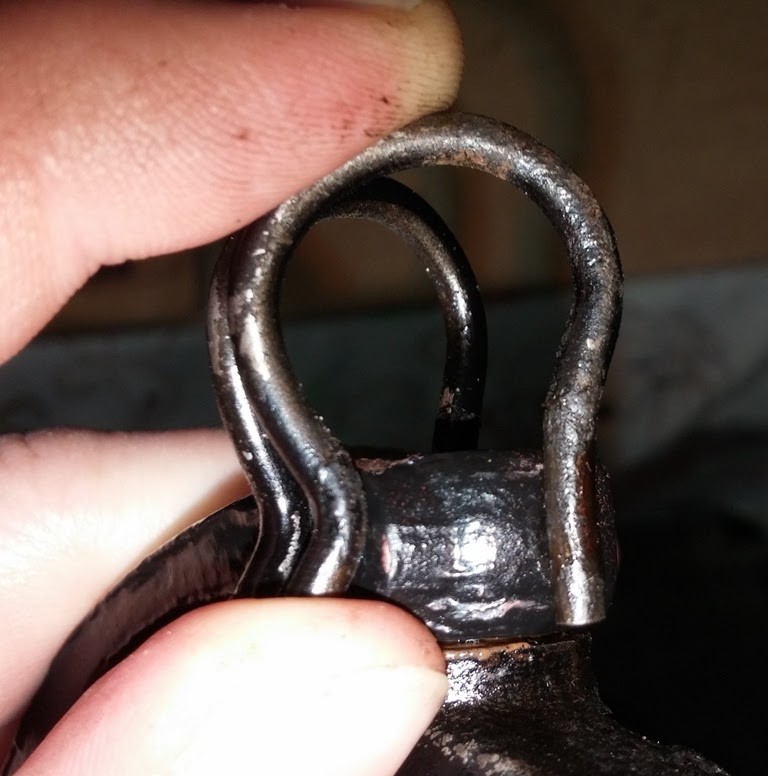
Notice that spring installed that the depth of the spring goes in a good ways and sits secured
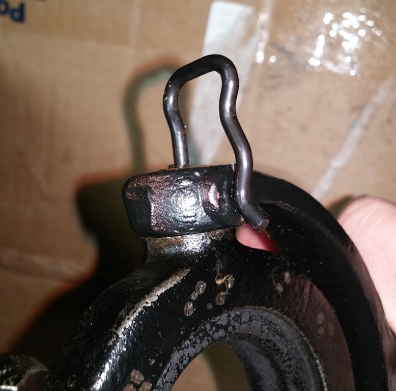
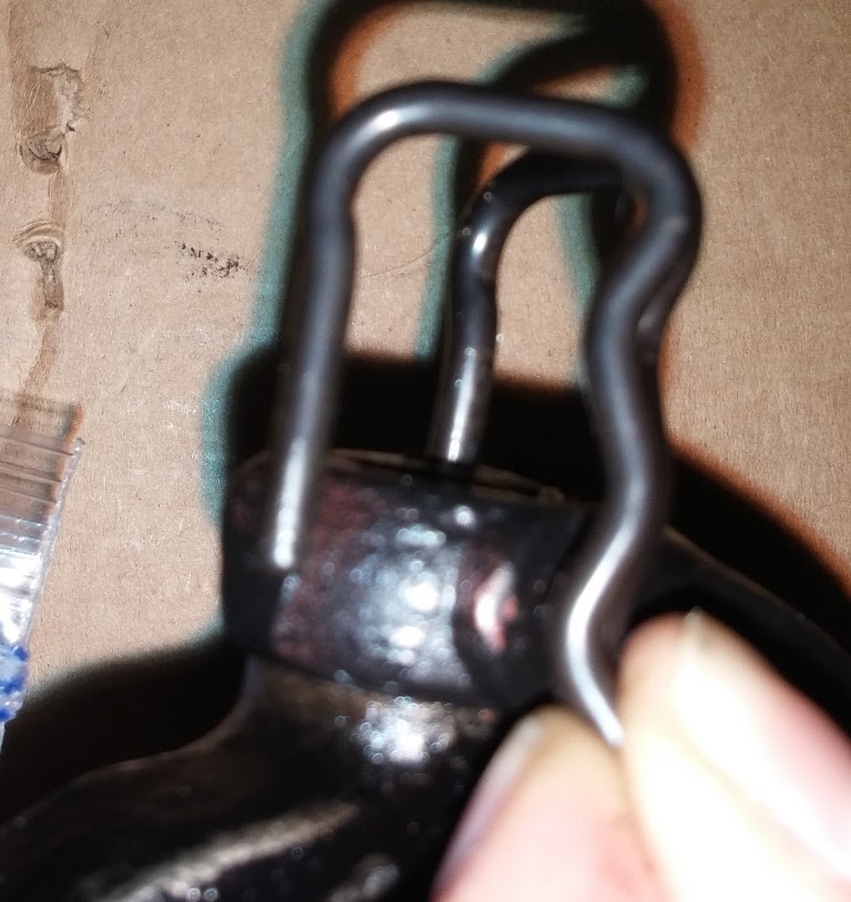
notice only about 1/4" goes in
When i took apart my 1929 Transmission, the Bottom Flywheel Cover, has a drain hole, an in that drain hole was a Cotter pin. not sure if the pin was to help get the oil out and away from the pan when it drips vs run down the side and hanging on.
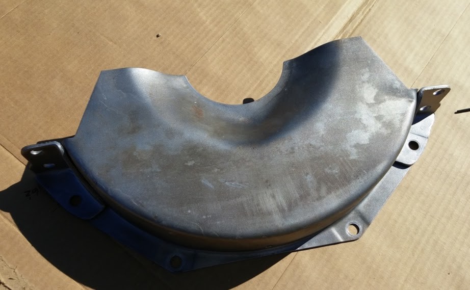
Is this factory or something the PO did ?!
Should i Put a new Cotter Pin in or ??
Here is a sketch i did up off how the cover fits and the spacing i have
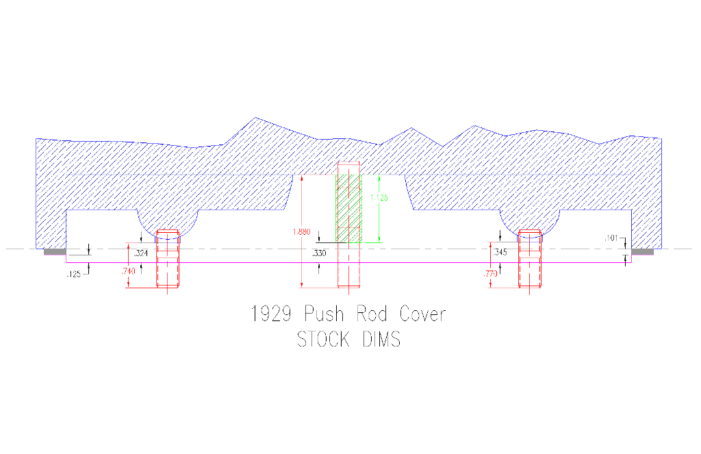
Red Dims are overall length of Studs
Green Dim is Spacer Length
White is the Space / Gap
Left Dim is Offset of Cover
Right Dim is Est Gasket Thickness
I am wondering what it takes to remove the fuel tank from my 1929. Since i am cleaning and checking everything as i go, figured i mine as well drain it flush it and clean it out.
Looking at the tank, looks like there are ONLY 2 straps holding the tank in place. Is this all that holds the tank to the frame ?? and to remove those 2 straps looks like there are two bolts/ nuts on the front side that hold the straps to the frame.
so if i support the tank, remove the fuel line from the tank, i then can remove the hardware, loosen the straps, and then slowly lower the gas tank down ?? then installation is the reverse ??
how can i check the fuel sending unit, and what does it look like ??
1-seems there is a plug of sorts on the bottom of the tank, i assume to drain the tank if needed ??
2-looks like the gas gauge is all one piece internal to the tank, and looks like i should be able to slowly thread it off and gently pull it out of the tank ?? any tricks/ tips or anything that i should be weary of when pulling it out to validate & inspect it ??
3-assume there are gaskets to seal the unit to the tank to prevent leaks, or just threaded on and that is all ??
Ordering some hardware for my 1929 Running Board & Apron. Looking at the MPL it list 1/4-20 @ 3/4 & 1 long then 5/16-18 3/4, 1, and 1-1/4 long which one are used to:
1-Apron to Running Board Sides
2-Apron to Running Board Ends of Running Boards
Looking at what I have on mine now is NO help, PO used whatever he had laying around, it is a hodge podge of hardware, types, sizes, materials, etc...
Wondering if there are any replacements for the Universal Joint Ball washers #348133 they are shown in red here: Washers 348133
seems i am missing one, and the other looks abused.
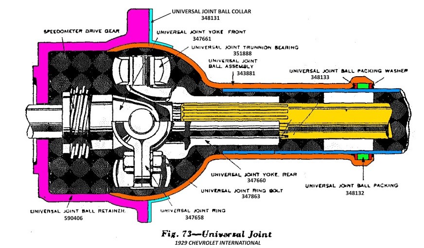
or can i make new ones, or is there a substitute for them ?? or do i need to find a WHOLE new Assembly (Mushroom)
looks like they tore one out and then tried to get the other one out, it is bent, warped, distorted, twisted, etc...
I was thinking to get a few cut out, with a slot so i could work it in like a spiral, and then put the o-ring in between.
not sure what my other options are at this point.
Thanks to Dave39MD !! He had a NORS u-joint housing sitting around, that i was able to acquire for my rebuild and i was also able to successfully rebuild the original one
I was able to source 2 Spiral washers to replace the lost & destroyed washers in my u-joint housing. I cleaned out the end, and deburred the housing where the washers & o-ring will go. this was to ensure the spiral washers sit properly and the o-ring would NOT get damaged.
Installed First Spiral Washer and then pressed it to the bottom of the groove.
Spiral Washer Installed
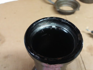
I then installed the second Spiral washer and pulled it to the top
Second Spiral Washer Installed
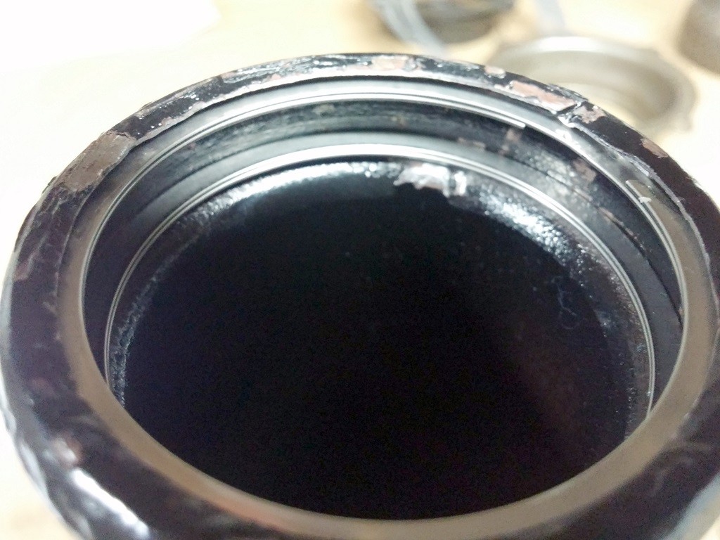
The o-ring now fits nicely between the two washers just like it should. and should be completely usable without issues.
I opted for the 2 turn vs the 1 turn, since the 1 turn have a gap in them and figured this would cause issues with the o-ring, an edge to pinch on or a gap for the o-ring to try to escape.
really happy with the 2 turn easy to install and looks great. NO sharp edges and easy to remove. as you can see the custom lip they have for removal !!
I contacted the Manufacturer directly, as we do tons of business with them for the company i work for. gave him some specs and he sent me some samples to try. a few 1 turn and a few 2 turn.
If they work he says he can produce some for me in batches of 100 due to production run limits. so that would be 50 sets and would be pretty cheap, under $10 a set maybe even less !!
I had them make them fit a little tight, so they do NOT slop around in the housing. should they be loose or snug ??
Well last Monday i was home and was finally to the point of putting the engine & transmission back into my 1929. i double checked everything and then rolled the car back half way out the garage, then set up my engine hoist, and figured out a way to sling and hook it up to drop it back in.
I used my hand dandy moving blankets from Harbor Freight, they work great as fender protectors. Also Taped on some cardboard to back of engine to avoid scratching up the firewall and engine itself. I did bump a few things going back in, so had to do some touch up on pain, mainly the frame.
1929 Driveline Ready to go Back In
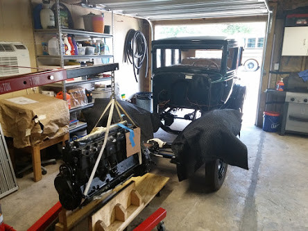
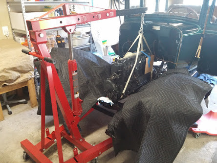
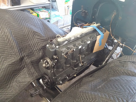
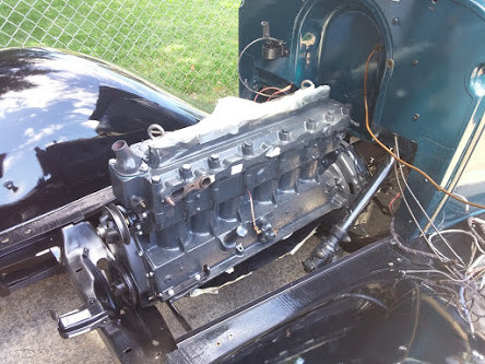 Engine is in, now to drop in the pans and then start bolting on the accessories.
5-31-2017
Working on putting Engine, Components, and Accessories back into the 1929 Bay. Wondering when is the best time to install the Splash/ Underpans ??
should they go in LAST after everything else engine, components, accessories ?
or should they on right after engine is installed BEFORE components and accessories are installed ??
Thanks in Advance !!
While working on the car, i decided to remove the Hand Brake Handle & Assembly and Refinish it.
When removed from the car, hardware was corroded and the handle had seen better days.
1929 hnad Brake Lever Assembly
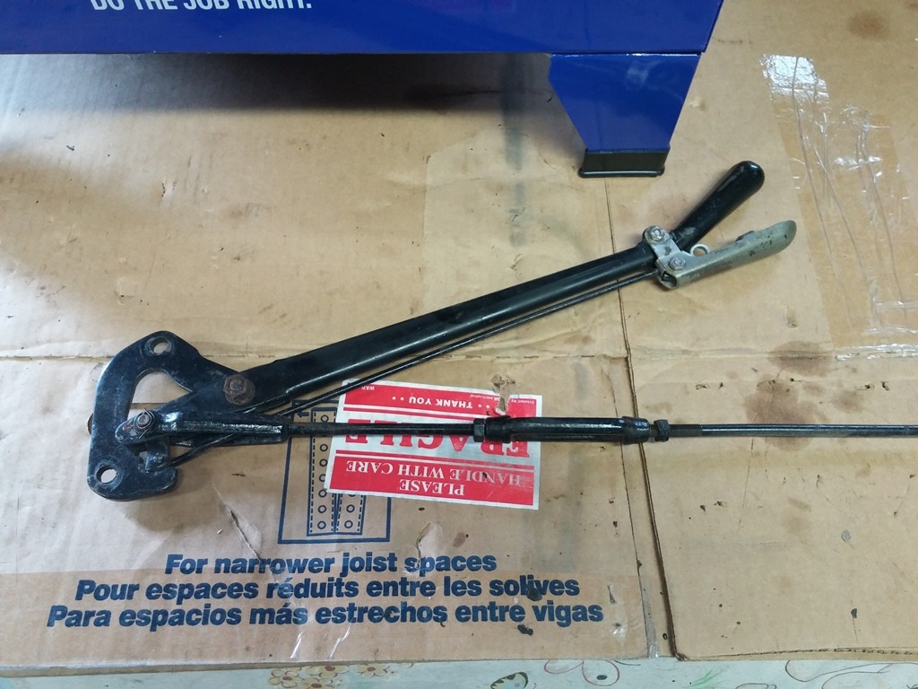
1929 Hand Brake Lever Assembly Close Up 1a
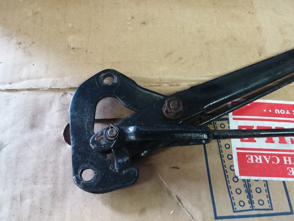
1929 Hand Brake Lever Assembly Close Up 1b
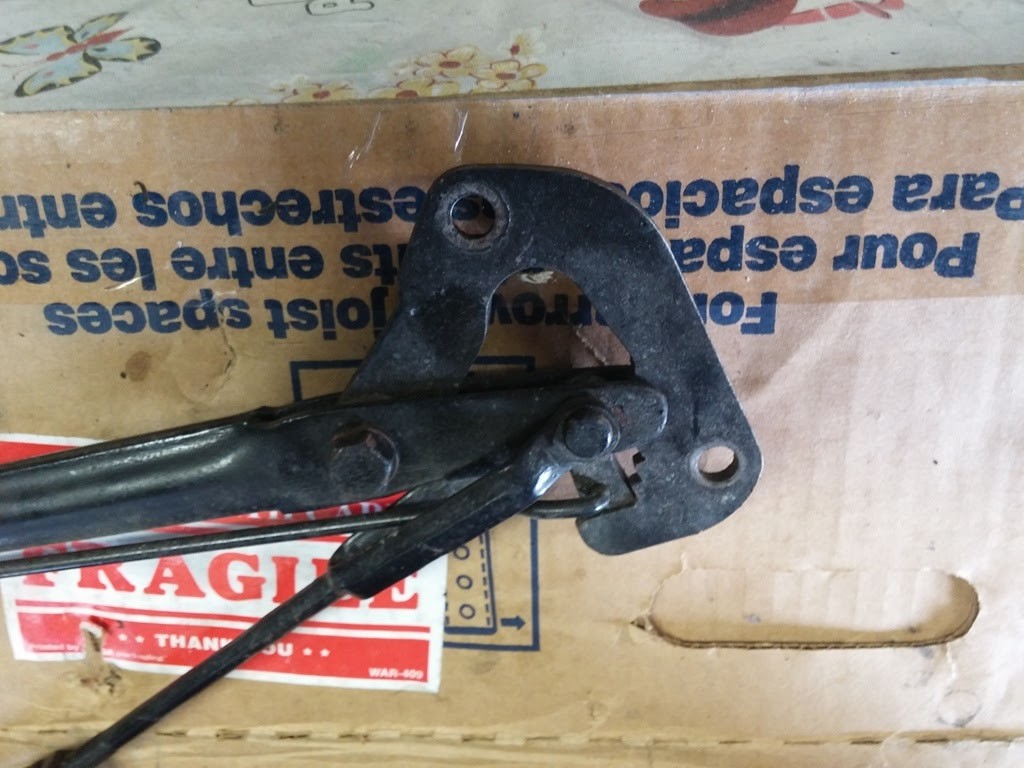
1929 Hand Brake Lever Assembly Close Up 2a
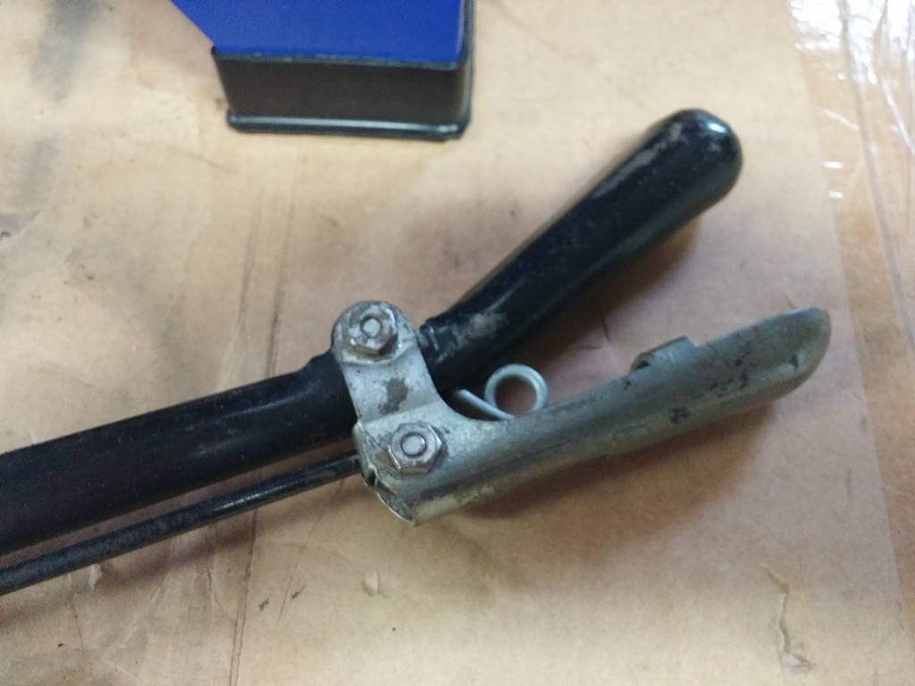
1929 Hand Brake Lever Assembly Close Up 2b
Took it all apart, Blasted it in my Little Bench Top Eastwood Blaster, using 50/50 mix of Glass & Alum Ox
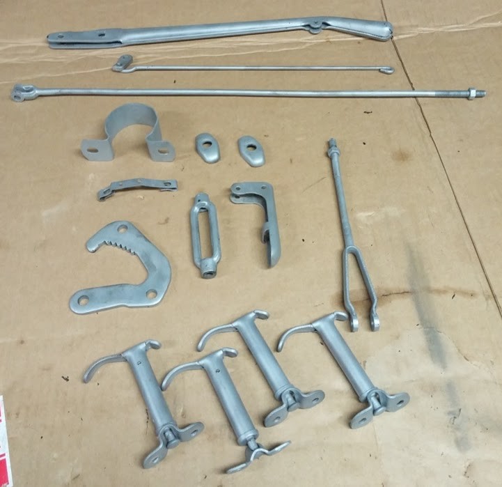
there are some other parts in the mix as well, blasted everything while i had the machine set up !!
Primed, and then Coated all the parts... Man What a Difference !!
1929 Brake Lever Assembly Parts Painted
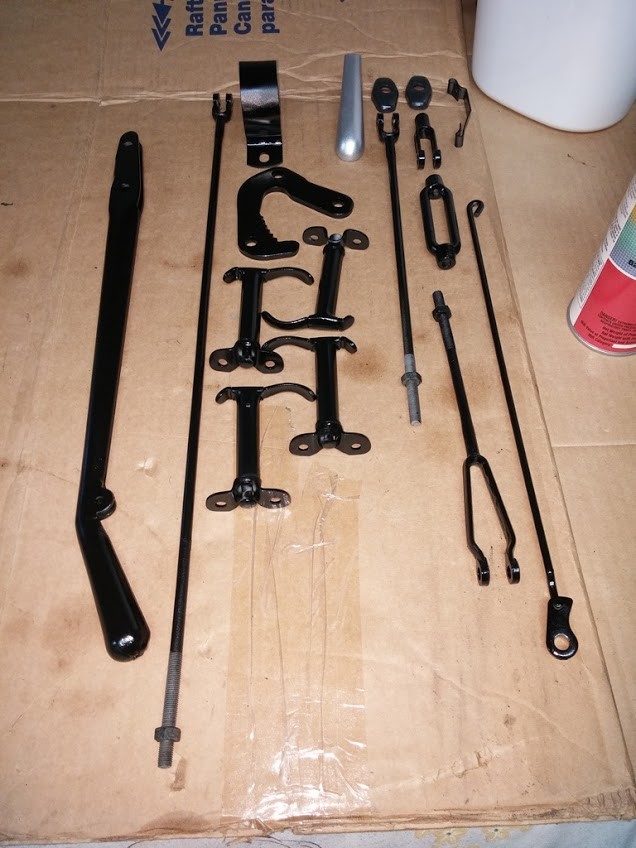
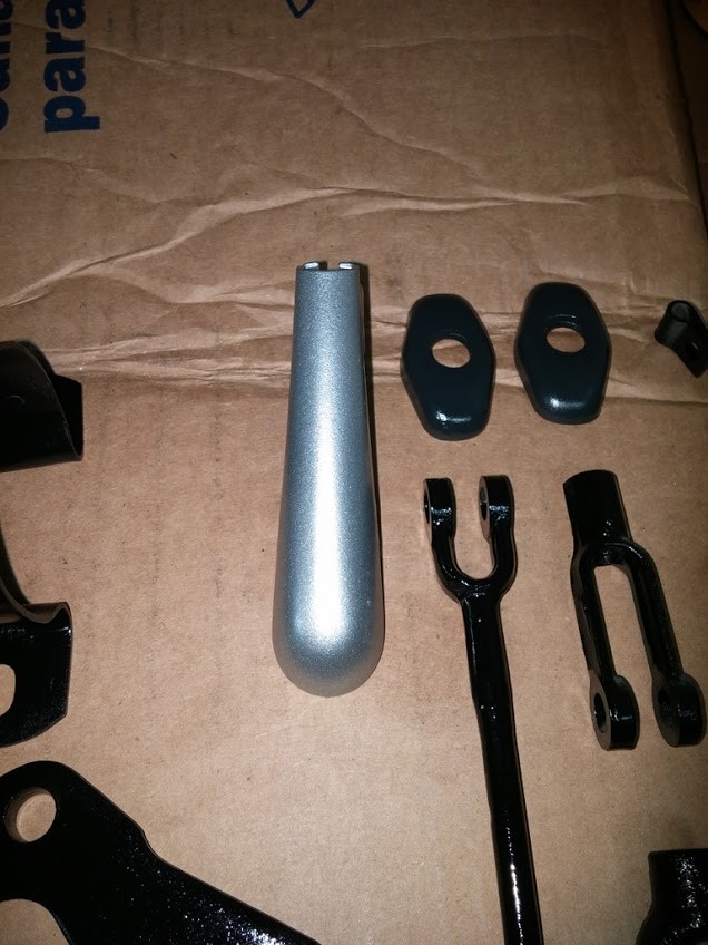
Have to let paint cure, plus I had to order NEW hardware to put it all back together. so that should be here in a Few Days... I HOPE !!
As most of you know i got my Engine and Transmission back in the 1929 Frame. now comes the fun part of installing all the accessories and parts that bolt on the engine.
All NEW Hardware was used to Install the Starter
Splash Pans were installed first, First up on the list was the starter:
Engine Trans Housing Where Strater Mounts
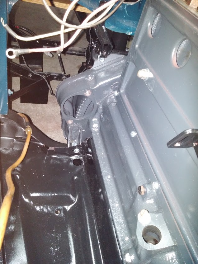
Starter Installed w/ Starter Pedal Assembly
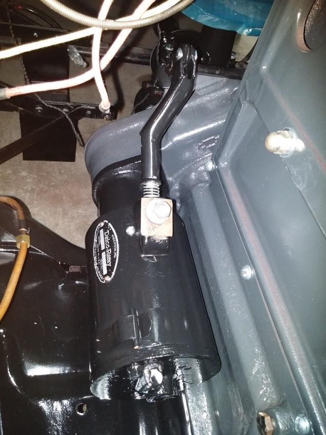
Side View Of Starter & Redal Assembly
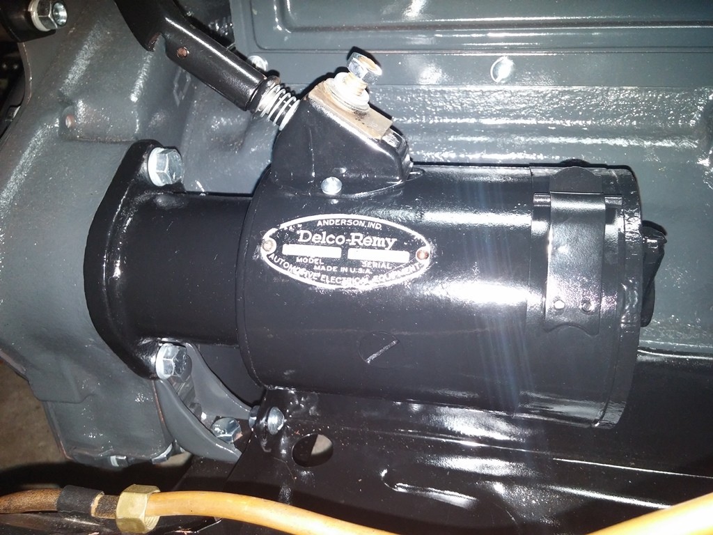
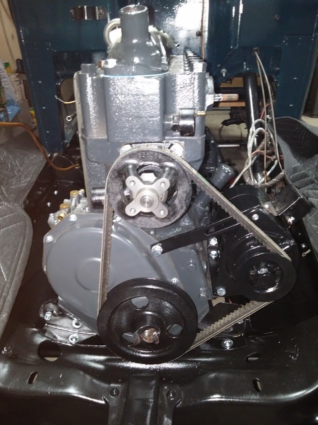
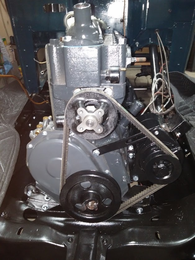
Once the Starter was secured, Next up was the Generator & Adjustment Arm. The Belt was also installed to assist with installation and proper adjustment of the Generator.
All NEW Hardware was used to Install the Generator
Side View of Generator Installed
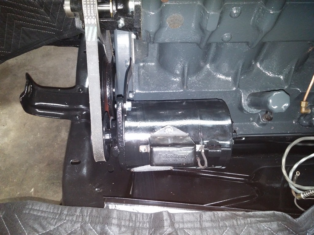
Front View of Engine w/ Generator Installed
After the Generator was secured and Adjusted, I decided to install the NEW C&P Automotive (Billy Possum) Push Rods & Caps in prep for the rebuilt Rocker Arm Assembly to go in.
C&P Automotive Push Rods & Caps C&P Automotive Caps Up Close
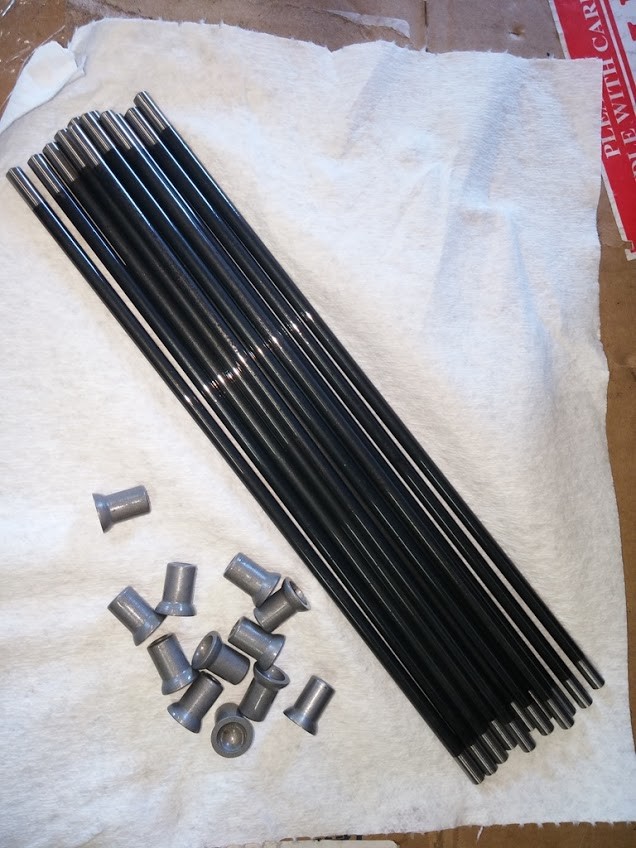
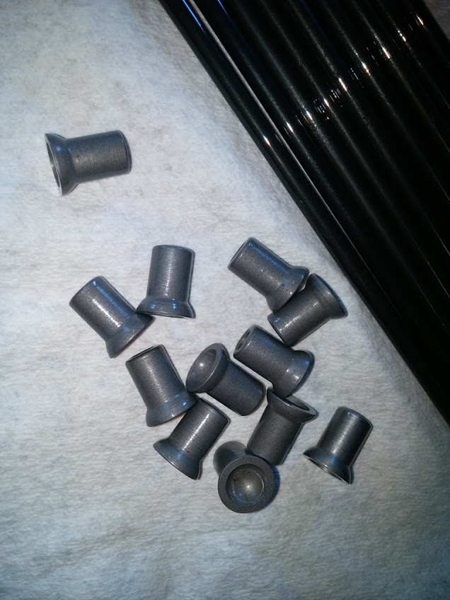
They come sealed in an airtight back with a light coat of oil on them to keep them protected.
Push Rods and Caps Installed
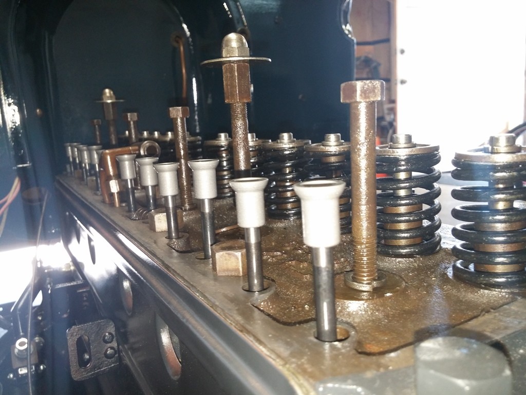
I also Installed NEW C&P Automotive Tappets, when i installed the Push Rod Cover.
Once the Push Rods & Caps were installed next up was the Rocker Arm Assembly. I had the COMPLETE Rocker Arm Assembly rebuilt via Rocker Arms Unlimited out in CA. These guys are very knowledgeable about the vintage Chevrolets. They have all the equipment and tools to do the job right, including creating the correct contour on the Rocker arm tips !! I worked w/ Gary out there, and he took care of me in every aspect. Read more and see Pictures of their work in previous Posts here.
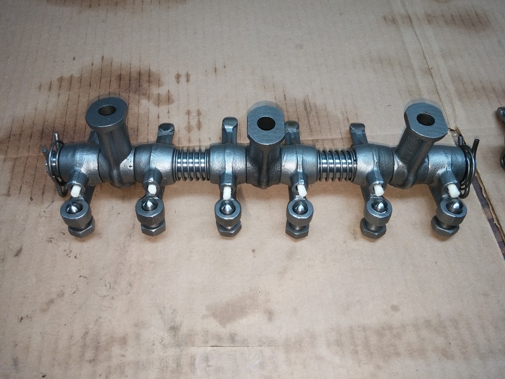
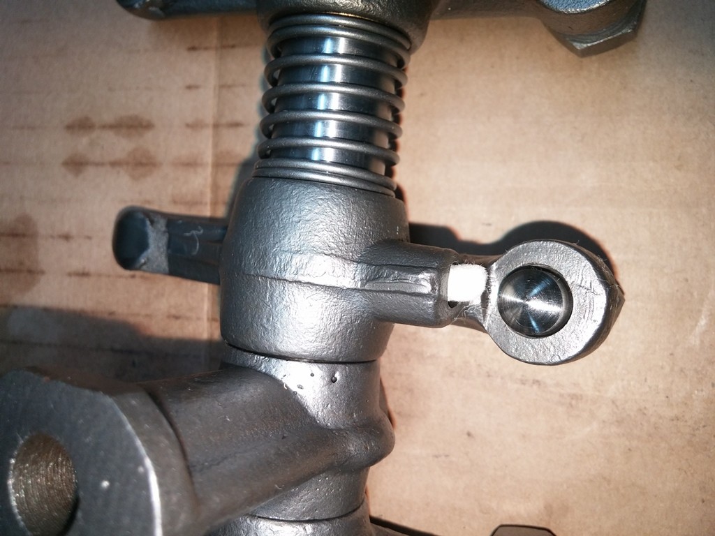
Rocker Arms Installed w/ Rods & Wicks
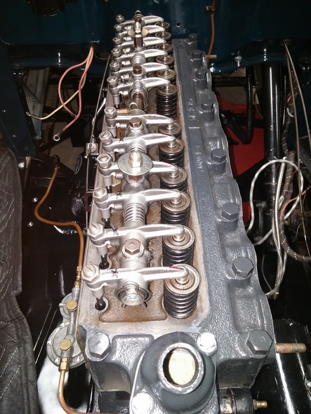
Wicks Instaleld w/ Caps Close Up
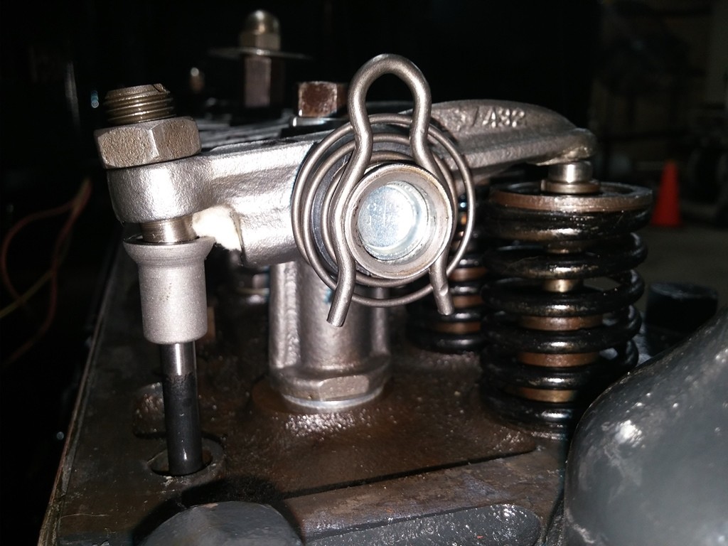
After the Rocker Arms, I set the valves, this took some time, as i checked and double checked to make sure that they were set correctly with Piston 1 @ TDC.
Once that was done Next to go in was the Distributor:
Distributor Installed
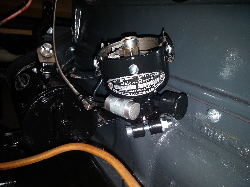
NEW Hardware was used here as well
I also took the time to set the points gap and then double check that while here as well. I am trying to get all the critical items COLD SET so that when i am ready i can try and fire the engine with little or NO issues... CROSSING MY FINGERS !!
Well next up was the Manifold Assembly !!
1929 Manifold Assembly Installed
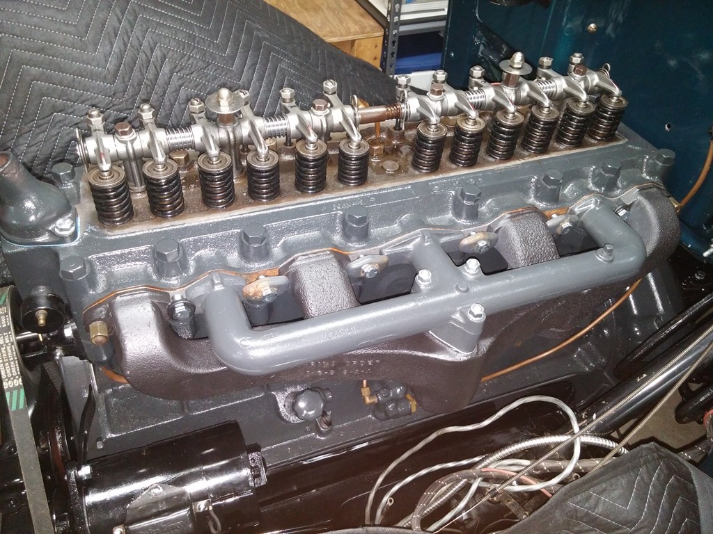
Side View of Manifold Assembly
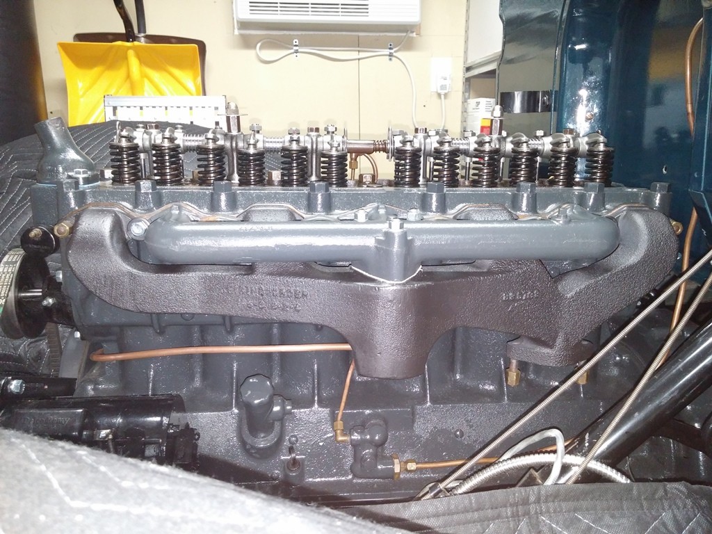
6-20-2017
i had to do the .060 shims under the posts because PO installed aftermarket, later year valves and they are taller than the stock, and they cut the push rods down to compensate. 1929 Head Check - Valves
so when i put int he rebuild arms, and then the NEW C&P Push Rods & Caps, when i tightened down the bolts to hold the arms in, it pressed open all the valves. even if i removed the adjusters from the arms. this was the only way i could get it to work. based on my math it worked out just fine. will see how it does once i get it running up and to temp and HOT Set the valves.
i checked my belt and ordered a NOS Dayco #24380 17A0965 per an article on here about belts. It is NON Wrapped, NON cogged Belt Made in the USA.
It is shorter that the GATES that the PO had installed.
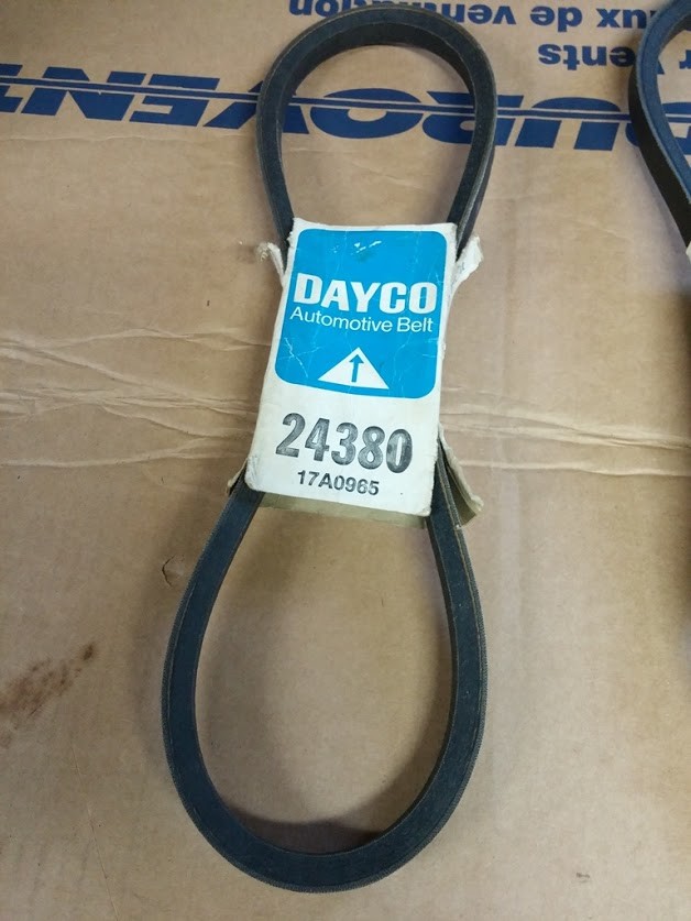
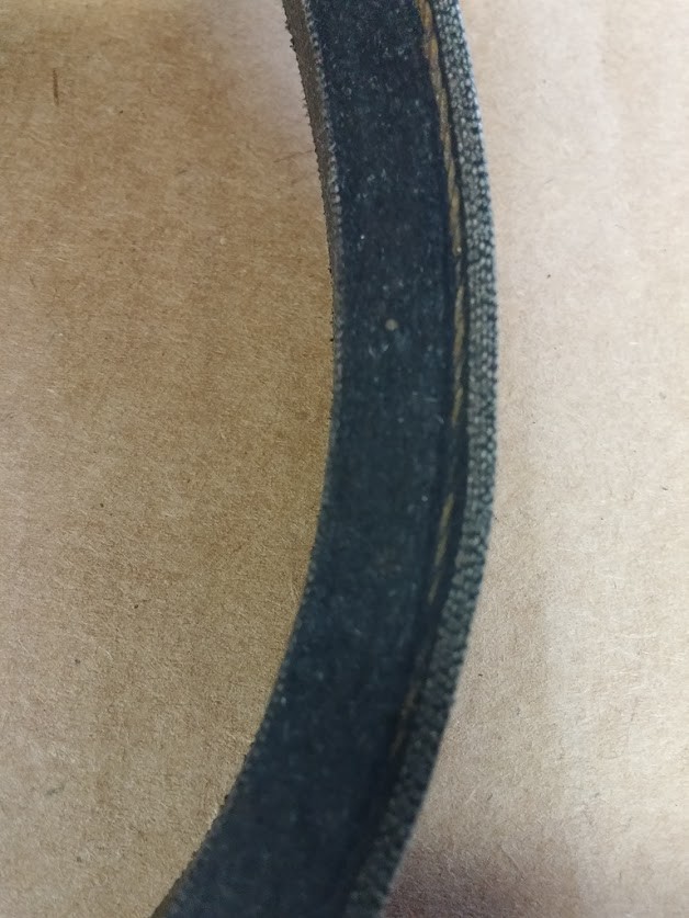
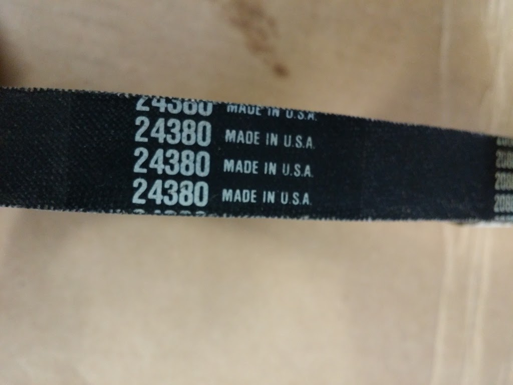
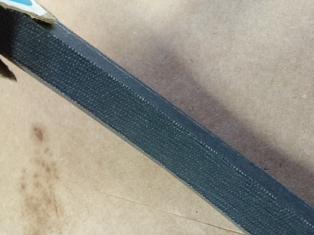
Installed the belt
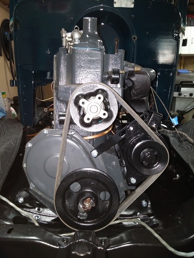
notice the angle from before to now
Got the Tank Removed...
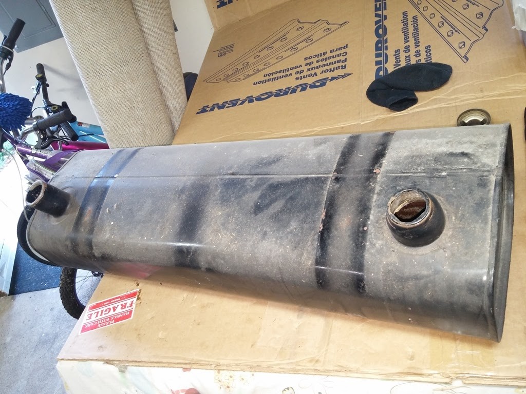
Flushed out the tank
now need to decide to seal or not to seal
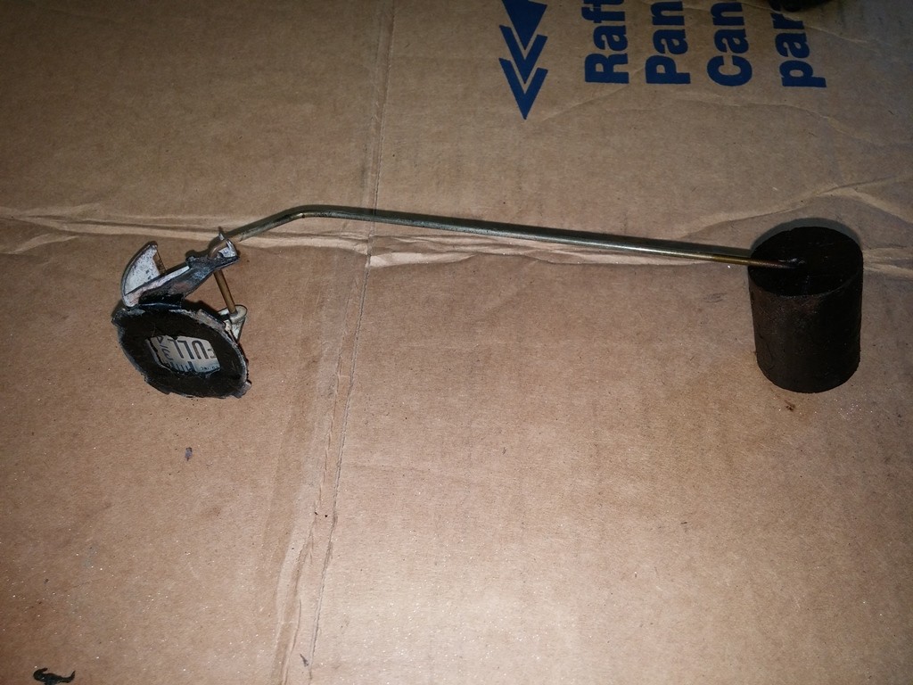
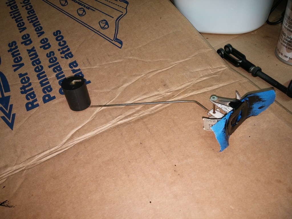
Going to replace the cork float with a new neoprene one i ordered
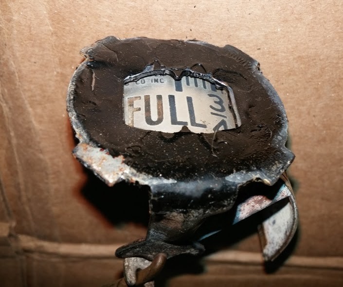
need to replace the gaskets around the gauge face, they are all falling apart.
well used the KBS Clean and soaked the tank, did this until the flush water ran clear, which was only 1 trip. water came out a little rusty color, but not bad.
now to clean up the Float, paint up the back, and then put it all together. i am going to repaint the tank while i have it out.
talked to the gasket maker today, he is willing to cut me some Viton Gaskets for the Fuel Tank Gage, and Fuel Tank Filler Cap
I Did the CAD Work, and he will cut them on the Water Jet, I just have to pay for the Material.
Anyone else interested in Viton Gaskets for the Fuel Tank ? would be 2 for the Gage end, each side of the glass, and then a new one for the inside of the Gas Cap. Total of 3 in the Set, doing 2 at .062 thick, then one at .125" thick. one of the .062 is for the Cap.
Viton should be a better material for the Ethanol, at least in chemical compatibility, or could do a Buna-N Cork Gasket Set.
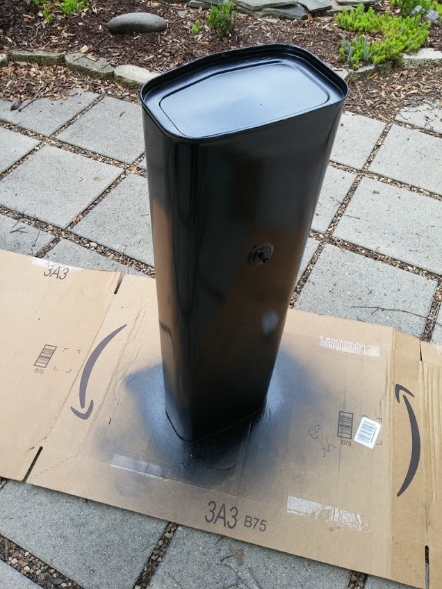
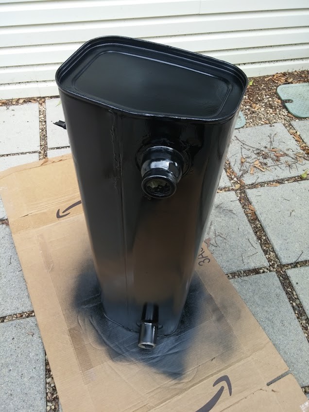
took and cleaned the outside the sand, sanded out the rough spots, and painted it all up. man what a difference![]()
stripped the fuel gauge down, and painted it up as well.
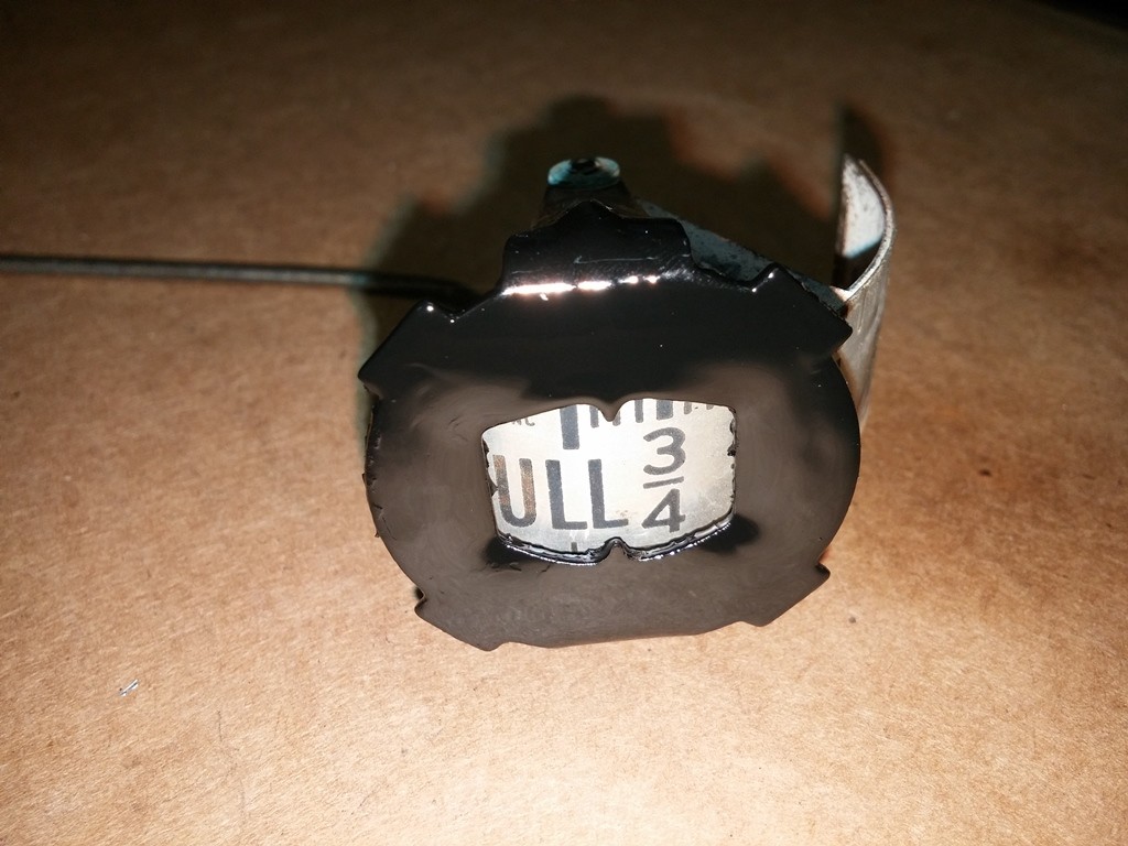
Here are a Few Shots of the Neoprene Float
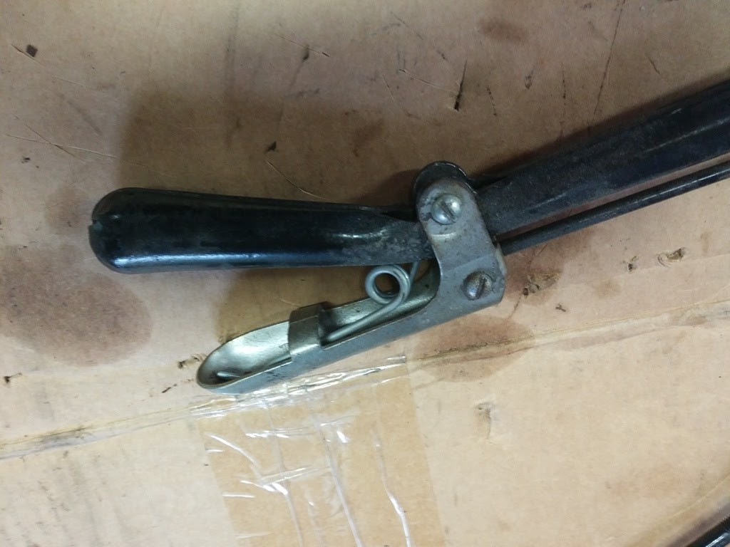
Trying to figure out the trick to installing the Spring in the hand brake, i bought it from TFS #FS-136, got the little picture and understand it no problem. I am not able to get the spring in per the diagram.
Spring is really tight and been kicking my butt. to the point i have ruined the paint on the lever and handle trying to get it in there.
Is there a trick to easy way to install the spring per the diagram ??
ok guys here is what i did, and man it was easy and went together like nothing. hope this helps anyone doing this themselves.
i removed the bottom bolt that holds the prawl and lever w/ lock. removed the prawl, and then pulled the rod out of the way of the handle. i then put the spring in the handle the way it goes, per the Filling Station diagram. then put the other end of the spring through the hole in the brake handle where it goes, then clipped on my needle nose vise grips, and pulled the handle and spring up and into place, and put in the first bolt to hold the handle in position. then gently release the spring from the vise grips. could also use something else to hold if needed.
ignore the tape, it held the handle while i touched up paint :)
Then you can flip the prawl lock and lever back around, put it in position install prawl and install bolt, then install the end of the lever in the handle and install hardware. consider it done !!
this was really easy and takes maybe five minutes, or maybe it took me 5, because i had been fighting it for days and figure this method out !!
IF is it in the car, not sure you can do it this way. but it is easy to remove and well worth the time to make this easy on yourself !!
Great car !
Posted by Diggymart on 9/7/19 @ 3:48:57 PM