You must be logged in to rate content!
3 minute(s) of a 100 minute read
1-24-2013
1-24-2013
Got around to scaling my MAFv last night. Results were less than stellar. It seems that the Fujita Intake may have a significant amount of turbulence right around 2.25V or approx. 25 g/s... this is especially unfortunate since that is the typical cruise airflow and likely responsible for my large variation in LTFT over a short period of time.
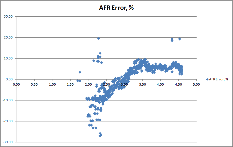
On another note, looks like the pulls at only WG pressure (9PSI) are around 270g/s airflow. Since I will be looking to target 20-21PSI, it is likely that my stock MAF sensor will peg (300g/s max). Fortunately, the MAF hack allows 16-bit ECU guys to increase the theoretical airflow maximum to 600 g/s. I'm currently writing this into my map. Since I'm on the stock-diameter MAF housing, I will still be limited to 352 g/s.
1-24-2013
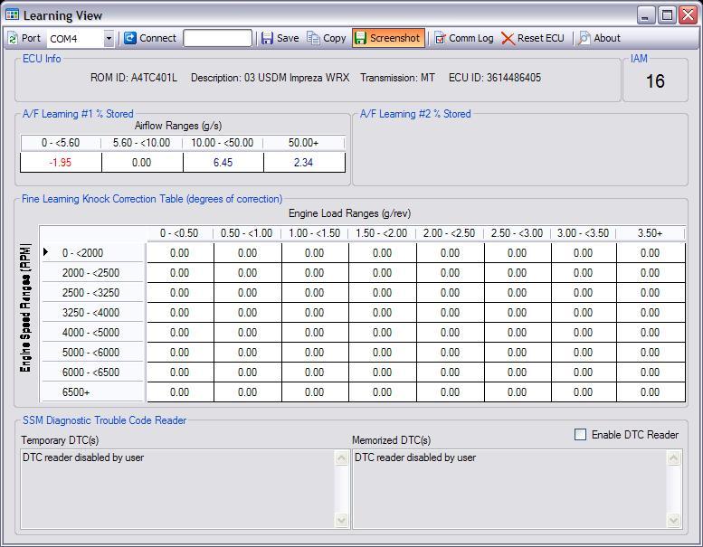
You can see the affect the Fujita intake had on my LTFT:
With stock airbox, injectors scaled:
With Fujita CAI installed, injectors same scale:
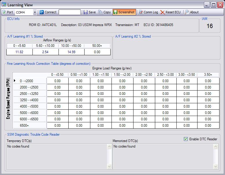
LTFT ranges are -14.99 to 14.99, so you can see column C is pegged and relying on STFT to bring the mixture to stoich for CL.
1-25-2013
Given the fact that my MAFv peaked at 4.6 volts during my untuned run, I made the decision to move to a 73mm MAF housing, which I purchased off NASIOC.
1-28-2013
Well the 73mm MAF housing and enormous ridiculous filter is installed!
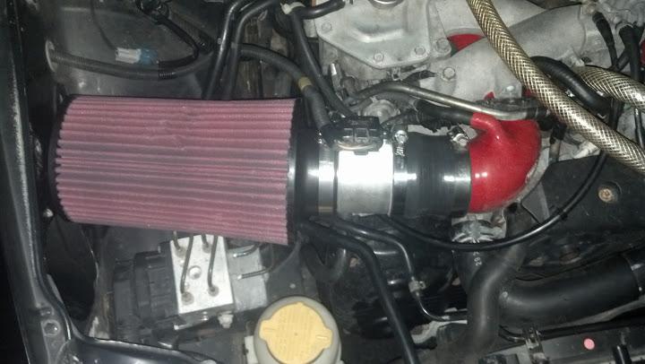
Because the diameter of the new MAF housing is 73mm while the stock is 65mm, the new housing has (75^2)/(65^2) = 1.26x more crossectional area. As such, I scaled the MAF sensor by 126% to account for the slower intake velocity per relative air mass. This was a rough approximation since there are other factors involved in the actual MAFv scaling (turbulence, fluid dynamics, etc.). I tell you guys and gals, as an engineer by profession and a physicist by education, I have NEVER seen a rough calculation prove so accurate in the world off-paper:
Game on.