You must be logged in to rate content!
185 minute(s) of a 390 minute read
11-1-2021
LS1 Powered S14
Compliments of SicBastard at www.zilvia.net
6/17/07
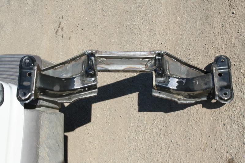
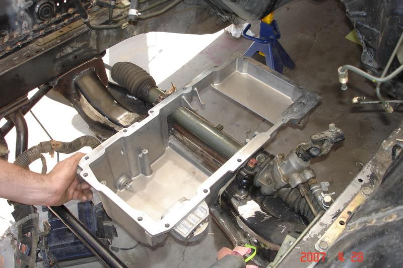
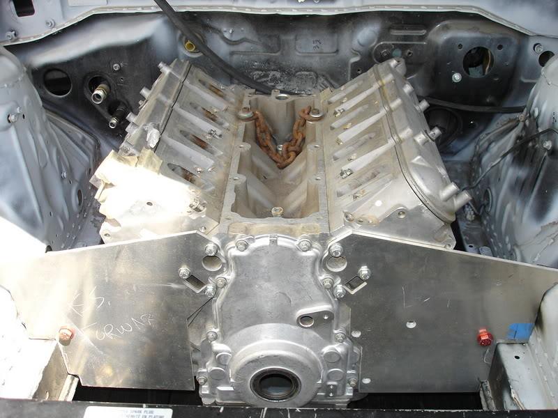
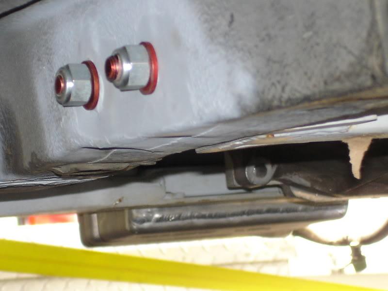
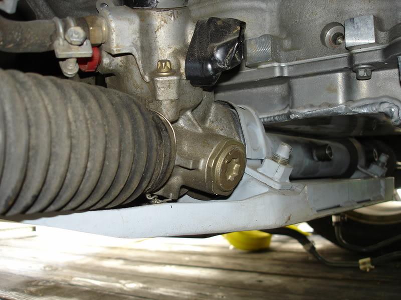
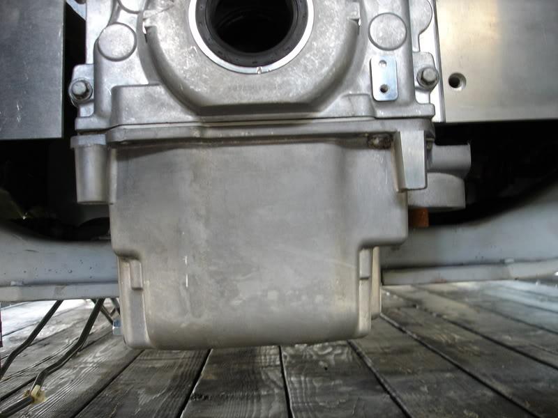
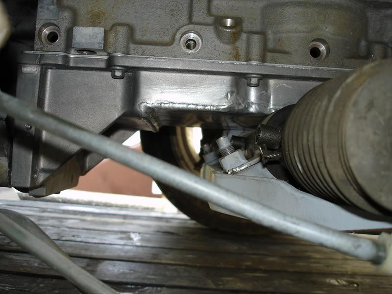
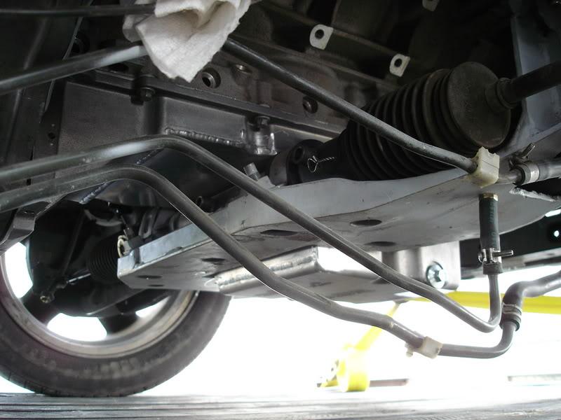
I've been obsessed with getting the engine and t56 as low and far back as possible. To that end I raised the floor of the GTO oil pan as high as I could and still clear at least a 4.125" stroke. Then I cut the ENTIRE front cross support in the middle of the cross member out, something that I havn't seen done before. This required first, reinforcing the bottom of the entire crossmember with 3/16th" plate and then two pieces of 1x1 steel tube between the steering rack mounts. Then I cut out the step at the back of the GTO pan sump so that the back of the sump could go right up against the steering rack.
Modded Crossmember
Milled pan sitting in engine bay
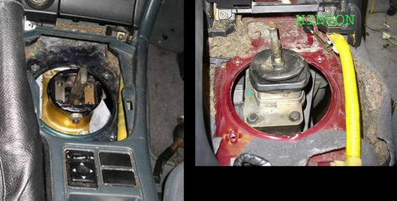
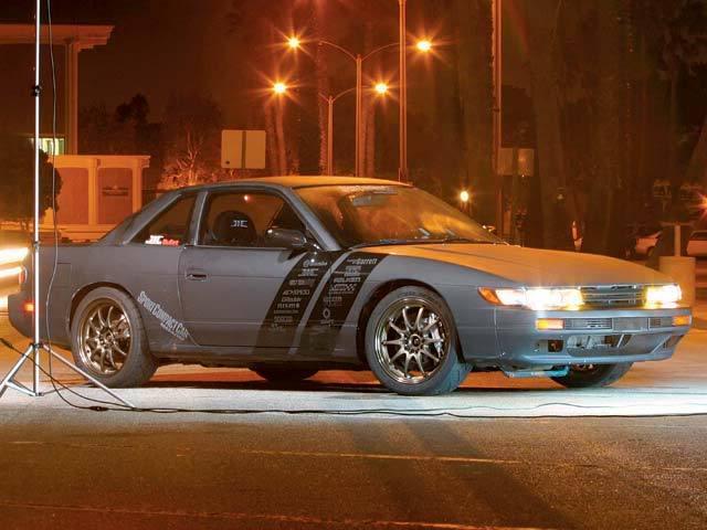
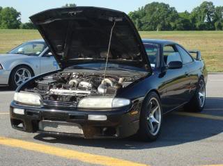
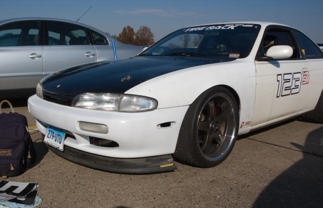
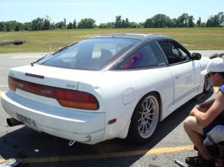
To give you an idea of how effective all this work is in setting back the engine and trans, here are two pictures of other LS1/S14s:
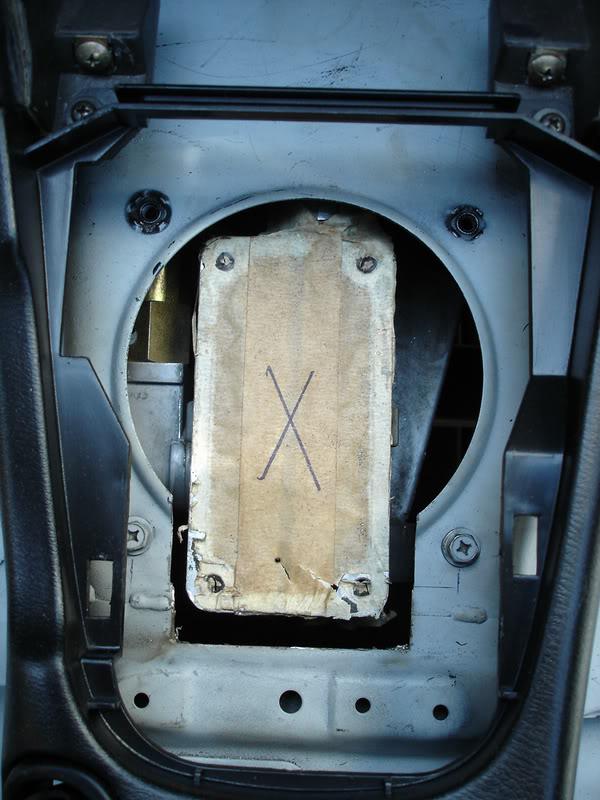
and mine:
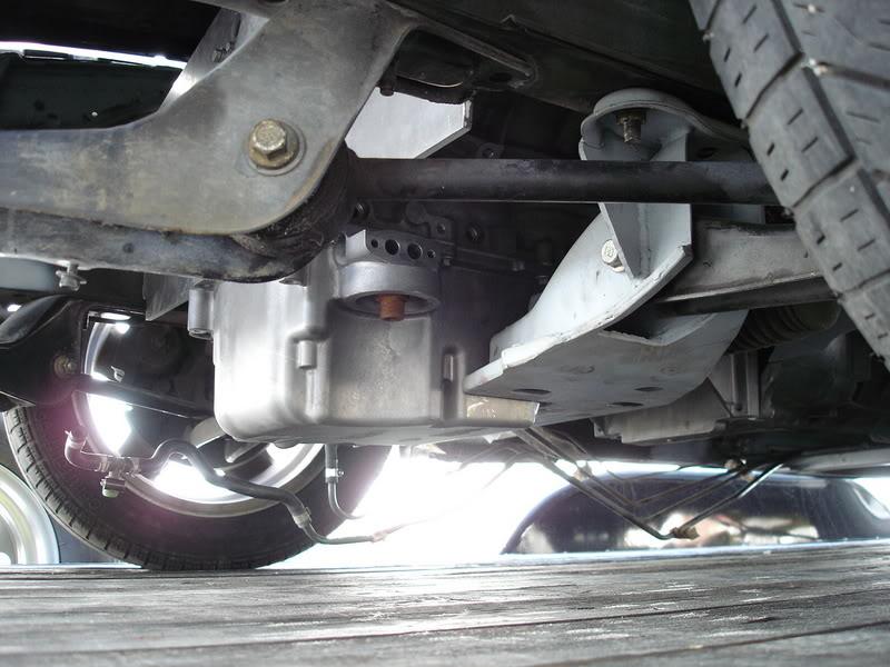
My new problem is that the engine sits so low that my GTO oil sump now sits 0.75" below my crossmember. And that's not accounting for the 3/16" that I added to the bottom of the original crossmember!
I did not lower the crossmember relative to the car, and do not plan on doing so. Now I don't know what direction to go with the oil system. I only have a junk LS6 block and havn't started the engine build so I can still go any direction that I want. I'd like to stay away from the weight, complexity, and $$$ of a true dry sump system. I have a used accusump system and originally planned on just staying wet sump, and using the accumulator for a little insurance. But the sump is sittling so low that now I'm worried about ground clearance.
I'm torn between leaving it as it is, modifying the pan to use the LS7 twin pump system, or taking 3/4" out of the bottom of the sump, maybe adding wings and baffles and staying wet sump.
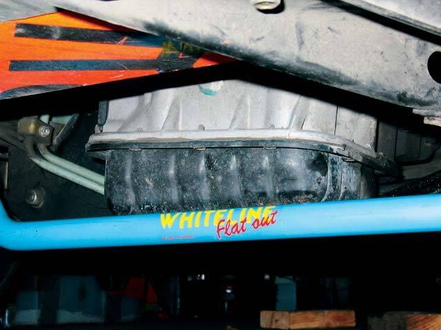
I noticed that the guys with project silvia at SCC had their anti-sway bar hanging below their crossmember after installing the front whiteline bar. Maybe I should just install a whiteline bar and call it a tubular oil-pan guard?
What Dave at SCC had to say,
"The front bar hangs down slightly farther than the stock bar, but there have been no problems with bottoming out. We like to think of it as a 27-mm tubular oil-pan guard.
...we hit one of those asphalt waves that get slowly kicked up when thousands of overweight trucks stop in the same place. The ridge of asphalt was high enough to hit the front anti-roll bar, lifting the car off the ground, bending the bar's pivot bushings and slamming the bar into the oil pan. The stock steel pan escaped only slightly dented, but we fear an aluminum pan would crack under a similar impact. If you're going to be sloppy, haphazard drivers like us, steel may be the way to go."
My engine sits further back than an SR so I think I'll be alright in that regard, I dunno?
note the blue bar hangin' low
What do you guys think?
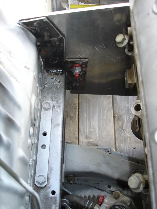
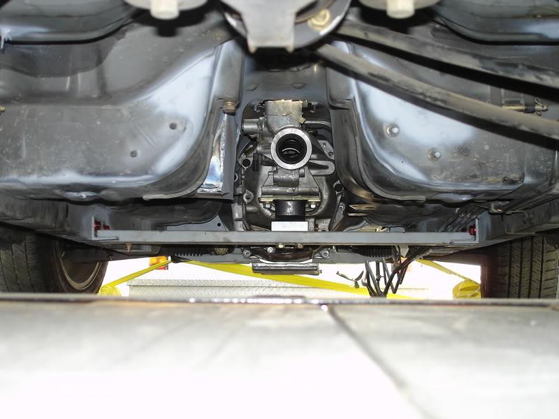
The clearances all around the trans are super tight in the tunnel, I couldn't raise 'em even if I wanted to.
6/21/07
some more pics
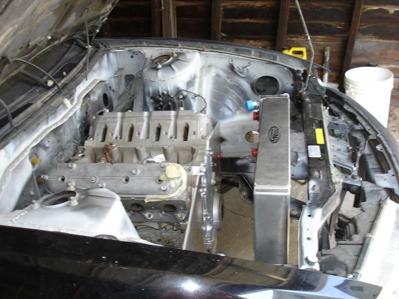
Right now I'm leaning towards staying wet sump and adding some side wings with baffles and these one way valves from billet fabrications out in Simi Valley California.
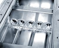

These guys make beautiful custom oil pans, plus they are near my old home town. Any one ever used their stuff?
I had to move so I'm still setting up my garage. Bought a new air compressor, and a new welder is in the works. The miller dealer is having a big show and tell day where you can try all the different welders next month, so I'll probably wait till then.
The LS7 heads are still with Richard over at WCCRH, and I just scored an LS7 intake on ebay for $200. I told Richard that I needed to go semi budget on the heads. He has a cnc program for the exhaust ports that add about 25cc/min of flow for $300, and he also has ti valves for about a grand. I will be getting neither of those. The heads come CNC'd from GM and I'm hoping to get away with spinning those rediculously large 2.2" intake valves to 7500 rpm with good ol brute force via WCCRH monster 1.450" (a big block chevy style) dual valve springs. The springs will require a little maching of the seats. The valves will most likely be manley stainless. They are heavy just due to the size.
My Old Speed inc billet LS1 fuel rails come no where near lining up. Now I just have to deside if I should Fab new mounts for the rails or if I should just get new LS7 specific ones?
It's also about time I got my ohlins rebuilt, so they should be going down to South Carolina here pretty quick. I made a really strong plywood shipping box, because the are my new "Precious."
And the last little thing, is that I just picked up a new steering shaft universal joint from the nissan dealership out here on rt 46E. The little POS was $90, but the old one was a little notchy, and there's no point in cheapin out now. I also have a set of 2006 LS2 GTO headers that I've bolted up. I'll see if the drivers side will clear some the steering rack u joint that I just got. The passanger side sticks way out and hits the frame rail, but there are no other clearance issues, so I think that a vette LS2 manifold would be fine on the passanger side. I'll keep yall updated.
-=Peace and Tire Smoke=-
11/30/07
Cam Plans
Well here is the cam that I cam up with and the engine specs all nice and neat thanks to the "Quick and Dirty Cam/SCR/DCR Calculator Spreadsheet Modified and Simplified by PianoProdigy" that I found somewhere over on LS1tech.com
Lift in inches__________________0.006 0.050 0.200
Intake Duration - ID (first number) 293 244 165
Exhaust Duration - ED (second number) 300 252 169
Lobe Center Angle - LCA (also known as LSA) 109 109 109
Intake Centerline - ICL (LSA - degrees of advance e.g. 114+2 = 112) 110 110 110
Intake Valve opens - IVO 36.5 12 -27.5 BTDC (- indicates ATDC)
Intake Valve closes - IVC 76.5 52 12.5 ABDC
Exhaust Valve Opens - EVO 78 54 12.5 BBDC
Exhaust Valve Closes - EVC 42 18 -23.5 ATDC (- indicates BTDC)
Exhaust Centerline - ECL 108 108 108
Overlap 78.5 30 -51 degrees
Bore 4.125
ST = Stroke 3.622
RL = Rod Length 6.2
Number of cylinders 8
Deck Height (how much pistons come out of the hole) -0.018
Piston Dome or Dish (- for a dome + for a dish) 2
Compressed Head gasket thickness 0.051 cometeic (stock is 0.054)
Cylinder Head Chamber Volume 62.5 (hopefully with the .045 mill)
Static Compression Ratio 12.06 :1
Dynamic Compresion Ratio 8.60 :1
Rod to Stroke Ratio 1.71 :1
Bore to Stroke Ratio 1.14 :1
The plan was to build a cam and motor that would make a ton of horsepower, but have less of a tire shredding tendency to help with traction out of the corners. Redline will most likely be 7500 rpm. I fear giong any higher because of the massive (read heavy) 2.200 stainless intake valves, that I have to use due to budget constraints, in the LS7 heads. I'm also using a milder lobe then most: the older comp "Xtreme RPM for LS1 Hi lift" Which will produce 0.630" lift on both intake and exhaust with the stock LS7 1.8 rockers.
I'm guessing that this engine will peak just under 6800 rpm without much fall off to redline. I'm using a stock but port-matched LS7 intake, and custom headers. The oversquare engine comes out to 392 ci. I think that the 30 degrees of overlap should be just streetable enough. It's the late IVC that I'm hoping will curb the dynamic compression ratio enough for the hi compression pump gas combo, and simultaneously help push the peak power rpm up above the 6300 wall that so many other LS1 engines seem to sit at.
This cam is all still theoretical; the heads and intake are not. So if anyone has any knowledgeable input/ideas to provide, I'm all ears.
12/2/07
I've heard two different, very reputable LSX engine builders mention these lobes in passing, and finally looked them up:
Comp Cams : XTREME MARINEâ„¢ HYDRAULIC ROLLERS - HIGH LIFT
These have the same ramp designs as the lower lift Xtreme Marineâ„¢ designs but have higher lift to enhance power
output with cylinder head and engine modifications.
LOBE RATED DURATION IN LOBE TAPPET LIFT @ THEORETICAL VALVE LIFT
NUMBER DURATION DEGREES LIFT TDC @ “0â€Â LASH ROCKER ARM RATIO
CAMSHAFT TYPE
.050 .200 106° 110° 1.5 1.6 1.7
3473 290 234 152 .360 .081 .068 .540 .576 .612
3474 292 236 154 .360 .085 .071 .540 .576 .612
3410 294 238 154 .350 .088 .075 .525 .560 .595
3475 294 238 156 .360 .088 .075 .540 .576 .612
3376 296 240 157 .360 .092 .078 .540 .576 .612
3411 300 244 159 .350 .099 .085 .525 .560 .595
3370 304 248 167 .380 .107 .092 .570 .608 .646
3377 306 250 166 .360 .111 .096 .540 .576 .612
3371 308 254 171 .380 .119 .103 .570 .608 .646
3372 314 258 175 .380 .126 .111 .570 .608 .646
3373 318 262 179 .380 .134 .118 .570 .608 .646
3374 322 266 182 .380 .142 .126 .570 .608 .646
3375 326 270 186 .380 .149 .134 .570 .608 .646
3447 330 274 190 .380 .157 .141 .570 .608 .646
also from the 2007 comp cams catalogue it says:
"These profiles use the same design techniques of the baseline Xtreme Energy
â„¢ Hydraulic Rollers but have been optimized
to increase power and durability when run at steady rpm for extended periods of time. Specifically designed
for big blocks with heavier valve train components."
I'm only interested in the intake at 244 @ .05", but its advertised duration (or duration at .006" lift) is 300, vs the 293 of the origianl lobes I was going to use. These lobes sound great, they are designed for big ass heavy big block valves, which is exactly what I'm running with my 2.200" stainless intake valves. I don't need these lasier lobes on the exhaust because they are a more standard (and lighter) 1.600". The larger advertised duration (at the same .500" lift) will also allow me to run a little more advance and still have a lower DCR. At 8.6 I was pushing it a bit before.
I'll call comps help line before making any final decisions, but here's some food for thought.
Who would have thought, Marine Lobes in a road racer?!
12/12/07
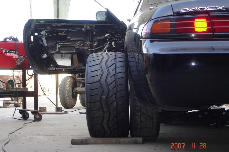
I'm not saying that anyone would be disappointed if they went with a set up from vengence. 575 hp at the crank is pretty impressive! But I'm confident that my set up will do better. Also the trick flow heads are not as good as a ported LS7 head on a large bore block; if you care, look up the dyno graps of cars equipped with both on ls1tech.coms dyno comparison forum, then look up both of their dry flows from the published flow bench results, you'll see I'm right. And regarding the "vindicator" cam: It's traditional split is too narrow for the heavily biased intake (or you cold say relatively poor flowing exhaust) on the LS7 heads. It's overlap is also much more narrow than the cam I'm proposing, which will cost power for the sake of driveability. And finally, it's smaller, which is fine for the 364 ci that it was designed for, but on my 392 will cost power again. I appreciate peeps throwing out suggestions, but before you reccomend that I scrap all of my parts and ideas for something else, I'm just asking that you do a minimum of research, or actually come from a place of knowlege before you post....in the mean time some cool pics of the halibrands and 275mm falken 615s.

1/1/08
I wasn't being defensive. I just get a little frustrated on this forum sometimes. I post up technical questions about camshaft design, and instead of replys, I get peoples' opinions on what sounds cool, and "vindicator ftw".You're right though, long tubes do sound nastier. The only reason I havn't mentioned them much before is that I was waiting to see what my final exhaust valve size was going to be, what the cam specs were going to end up at, the final bore and strokea, etc. Once that info and more is locked in there will be some serious posts on calculating header diameter, triY design, step location, blah blah. There' some serious power to be had with the right pipes!I just got my LS7 heads back from West Coast racing heads, and I've got to go pull my LS1 heads to see if the exhaust ports and header bolt location are the same. I hope they are because I'd rather use my scabby LS1 heads for the custom header mock up.And yeah those are halibrand cobra IIIs that were originally designed for ac cobra replicas. At first I was all excited to have original halibrands, but later found out that right before these models were made halibrand stopped being a US designed and made. All four wheels were slightly out of round (have sinces been fixed at Pico tire and wheel just North of LA) and the backs (17x10.5) were only made for a very short period of time and are a slightly different color than the fronts (17x9 without the deep dish for extra caliper clearance).
1/12/08
Halibrands definitely tickle my pickle!
And the progress is slow but steady.
...but it's about to come to a screaming halt for the next three months.
I have to move to Trenton NJ for a surgical clerkship, and I'm going to have to take call, overnight every fourth night. Then I'll have to move again.
Went over to my old stomping grounds TTP in Passaic NJ and media blasted my valve covers. Worked out great. Then I used a dremel with a 80 grit roll to remove the casting marks. I think I'm going to try and polish 'em.
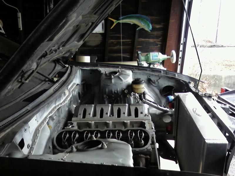
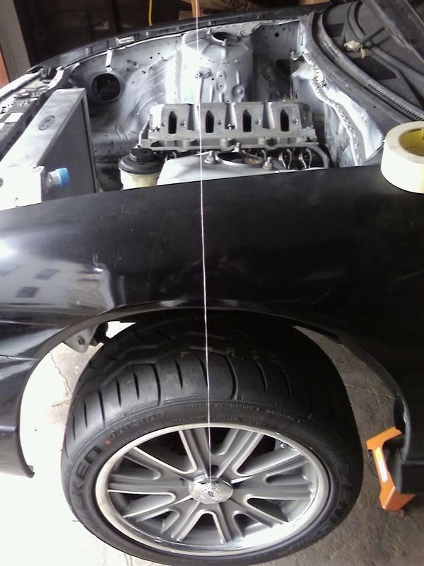
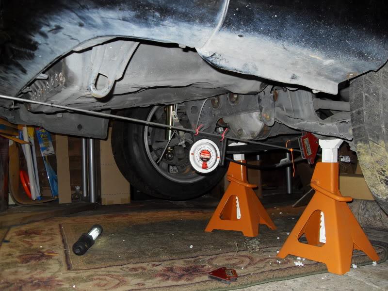
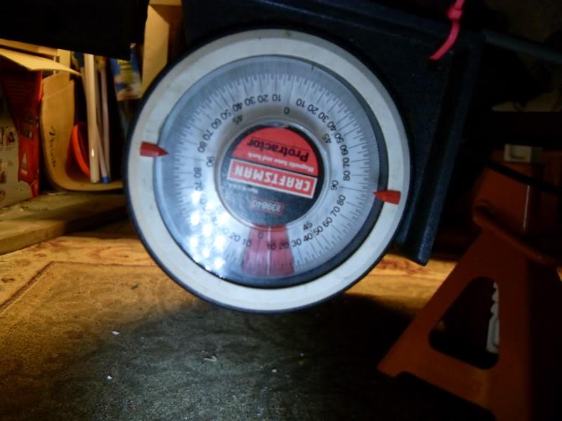
Took these pics for another thread to show how this bad boy is mid engine:
If you look close you can see the make-shift pendulum line that goes to the center of my front wheel. The car is level. And I think it's safe to say that this is a mid-engine car!
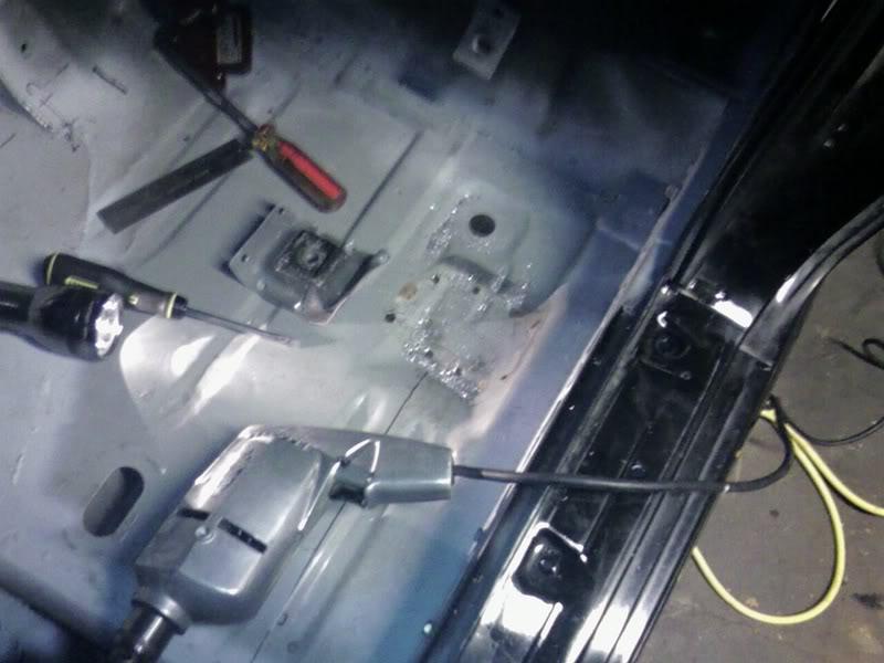
I've also been working hard on the seat mounts, because A: I want them low, and B: I want the seats in their final position before I weld in the harness bar.
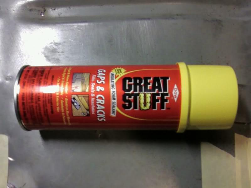
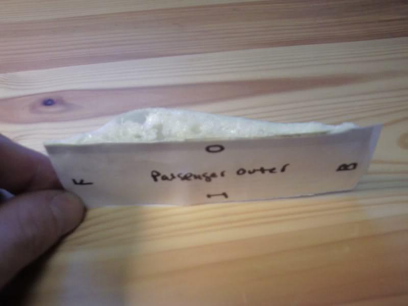
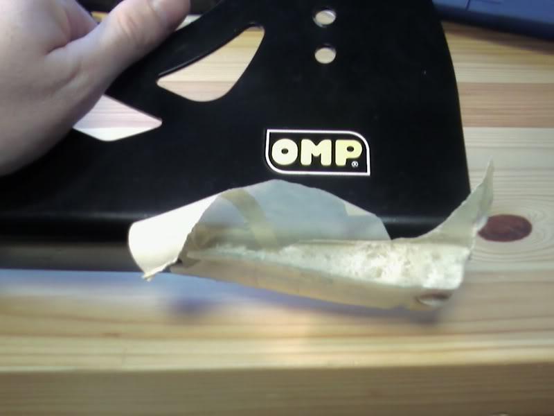
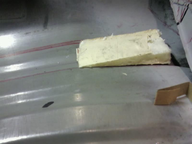
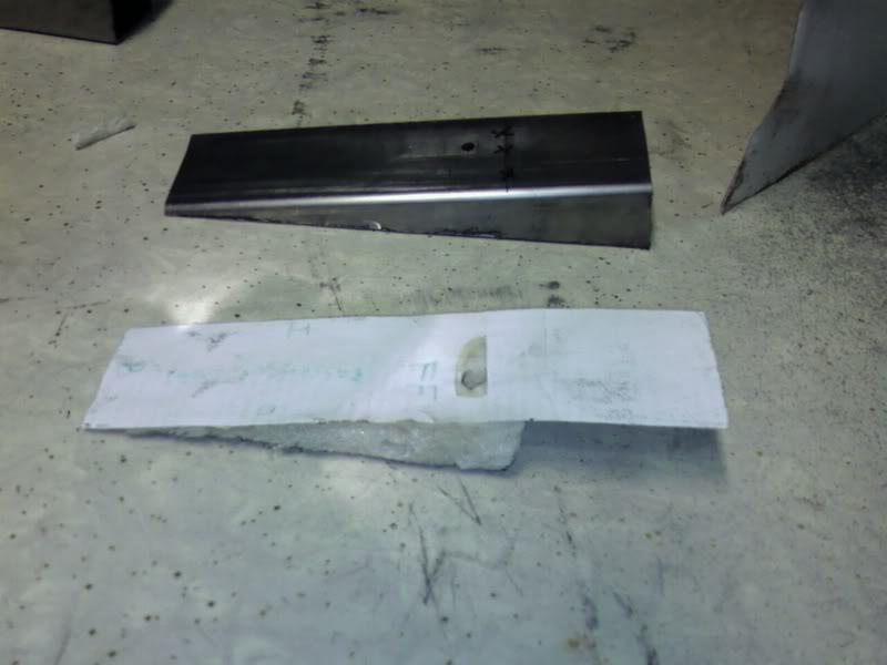
First I removed the mini pilar that holds up the outer/rear stock seat mounting point, and then masked off everything. In order to make a template for the odd shaped floor, I bolted down my OMP seat mounts and injected some insulating foam. Cardboard templates may have been easier, but it was a fun experiment, and it worked out perfectly.
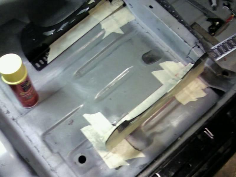
Notice the heater sitting in the car so that the foam would cure in my F'n freezing garage!
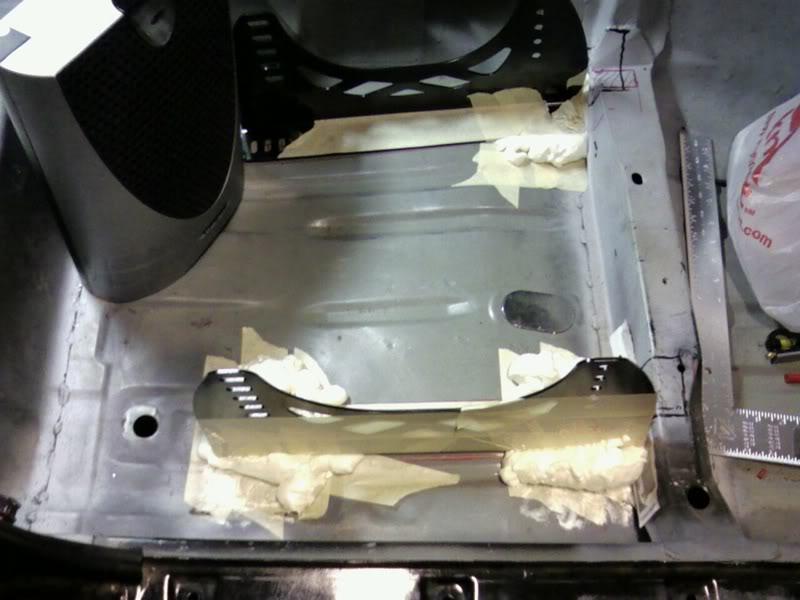
1/30/08
The LS7 heads have forced me to go big bore. I knew this when I bought them, but I naively believed the GMPP catalog that said that they will work with a 4.065 bore which ment I had the option of using a $1400 brand new L92 block. According to my head builder, who I believe over the catalog, 4.100" is closer to the truth. Incase you didn't already know the stock bores are:
LS2 4.000"
LS3/L92 4.065"
LS7 4.125"
Road race engines have been succesfully built utilizing LS7 heads on .035" over L92 blocks (yields a 4.100". But of course you're not left with much cylinder wall left, and if anything goes wrong, you can't overbore, you have to sleeve. Also, this is all presuming that you're starting with a block with almost no core-shift, good luck finding that as the L92s are notorious for having odd sleeve placement/core-shift.
So I've been looking into the other big bore options out there. Since a C5R or Warhawk block is out of my price range, that leaves me with the
1)stock LS7 $2400 new (maybe $1800 used)
2)Katech sleeved "budget LS2" something like $4000 (doesn't seem very budget to me).
3)darton MID sleeve (actually strongest on a LS1 block) but you're looking at $1000 for the machine work, another $1500 for the sleeves themselves, and then of course you need a block. So lets say you get a good deal on a used LS1 for $500, once you're done with shipping, we're talking at lest $3100
4)Iron LSX: can be had for $1800, but it will still require stress relieving and boring (it comes stock at something like 3.900" bore). Oh and did I mention that it's like 120lbs heavier than anything mentioned so far.
5) LS2 block with Darton Dry liners. What I'm leaning towards right now.
Require less machine work than the MID sleeves, and cost a bunch less for the liners themselves. Unlike the MID sleeves they do not require evans coolant and pump (a hidden $600 of the MIDs). You can get the machine work and the liners together for $1500. I can probably get a used LS2 block for south of $750, and you're looking at a total of $2250. Compared to the stock LS7: the darton dry are made of a much more ductile/stronger steel, can be bored out to 4.190 vs 4.155, and can safely support the pistons with longer stroke cranks, because the sleeve is deeper than even the LS7 (which has the deepest sleeves of the stock blocks).
3/3/08
I got a little pm today re the ohlins:...What I'm wondering just how much do they charge as I was looking into buying a used set and how long is the turnaround time? Please let me know...The short answer is 4 months and $300 if its just a simple rebuild.The long answer is...I just got off the phone with Tony Martin at Ohlins. Turns out my front struts are in pretty bad shape, but still rebuildable. So they are probably going to sell me a new set for the front at a good discount (I think this may be because they didn't bother to fully disassemble them before ordering the parts 3 to 4 mo ago, and they don,t want to ask me to wait another 3 mo). The rears required less work and the rebuild for them both should come in around $75 per corner (that includes new seals and adj. knob repair). I shipped them off to NC on Nov 10th. They didn't get the parts they needed till the end of January. Shouldn't be much longer now. There are two guys that I know of who work on these there, and they are quite often traveling, doing trackside support. Hopefully in the future that will make the waitng worth it.
4/23/08
So I finally scored one of these on ebay the other week.
They were originally spec'd out by lingenfelter when they built the spec LS1 motors for the ASA race series.
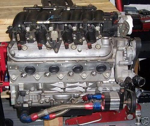
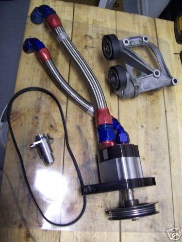
I think that it's the third one that I've bid on over the last three years. But this one I won! It is a single stage scavenge only pump that was built by razor. Razor is a little unique because their pumps internal gears have fewer teath and therefore (supposedly) flow more oil for a given section length. But another neat feature is that they make crazy deep section lengths. This single stage is a whopping 1.825". Trust me that's big in the world of dry sump pumps. I wrote to razor about a rebuild on the pump and about the possiblilty of adding a few stages to it to increase the crankcase vacuum.
This was their reply:
Dru,
The price to convert your single stage pump to a two stage scavenge pump is $350. The price for a three stage is $479.
This is figuring new shafts, studs, fittings, pumps bodies, and gears for the new sections.
Razor
At first I thought that I would just go nuts and add two more monster 1.825" scavenge stages. At that point I would probably be pulling close to a full 15 psi of vacuum. With that much sucking going on bad things can start to happen to wrist pins (because there isn't any oil suspended in the crankcase air), so then you have to add piston oil squirters. It just kind of snow balls. Luckily I don't have to worry about engine mounts being in the way. But I do have to worry about the lines hitting the starter If I add too many stages.
I'm going to convert my gto oil pan to be more shallow and add a pick up or two or three. Then I'm probably going to mount a big fat oil tank in the trunk. So the beautiful, all steel, moroso LS1 dry sump pan that came with my kit is for sale here on ebay. If you're going to modify an LS1 oil pan, this is the one to have. Trust me, you don't want to be welding on cast Aluminum!
http://cm.ebay.com/cm/ck/1065-29
296-2357-0?uid=85924721&site=0&ver=LCA080805&item=130217297 961&lk=URL
In other news I'm getting ready to move for the 4th time in 3 months come June, and I've been futzing with installing such mundane things as working locks and windows, just in case the car has to sit in storage for any length of time this summer.
That's all...
Peace and Tire Smoke.
So I got the Razor pump mounted, just so I could check the clearance that I'd be left with if I converted it to a 3 stage. I'll clean up the motor plate/mount later on a mill. There should be zero issue with the starter clearance as I mistakenly feared before.
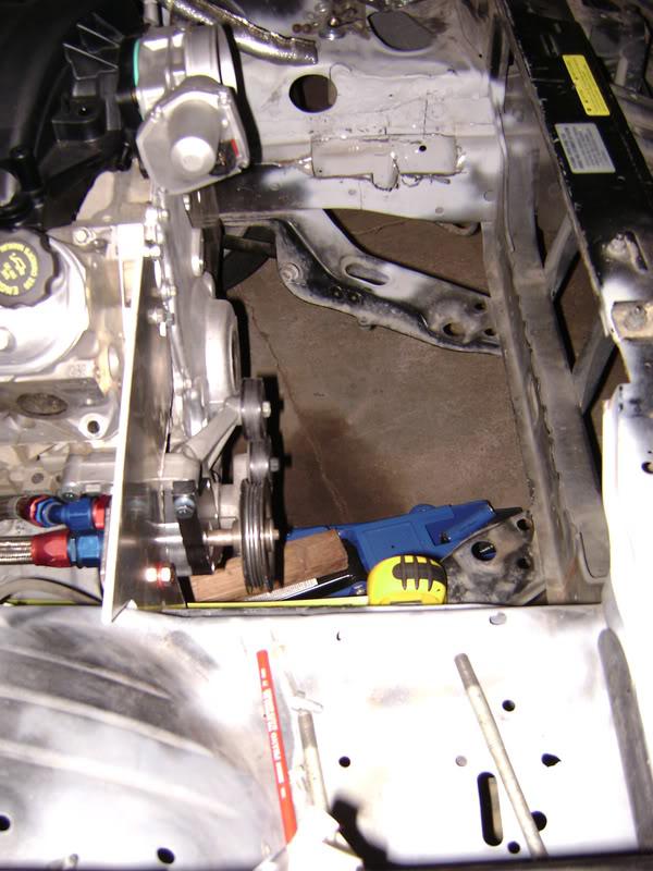
you can see the passenger side mid-plate (sandwiched between the block and bellhousing) pretty well in these next two:
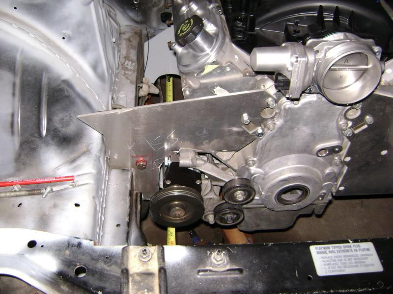
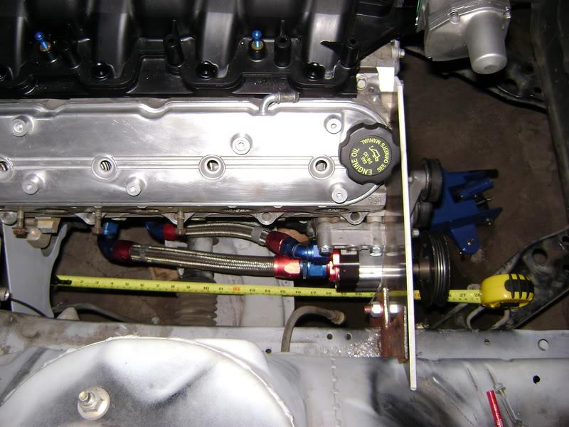
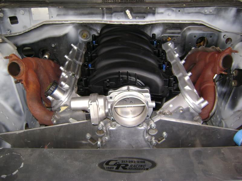
I finally got around to trying to space out the 05 GTO driver side ex manifold to see if it would clear the steering knuckle/universal joint. Almost... There is a lot of grinding that could be done on the inside of the manifold though, so it still may be possible for anyone looking for a stock alternative. The passenger side will not work from the GTO because it sticks out too far laterally and hits the "frame".
Just for fun before I give them back to TTP (thanx for the loan)!
Twin Turbo anyone?
9/2/08
I found these pics comparing the stock KA 5-speed to the t56 6-speed that's bolted up to the LS1 over on nico forum, as posted by "574-240sx"
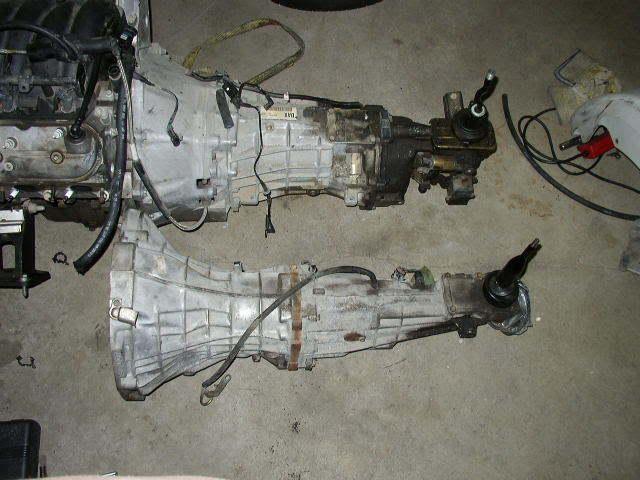
You can also see from the pics why you end up having to bash the hell out of your trans tunnel to slide the t56 back up in there.
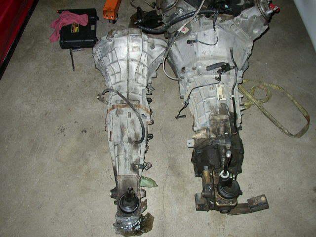
The stock one is LONGER!!! I never thought it about, but this is why the Hinson kit comes with a steeda long reach shifter, because with their kit the shifter ends up sitting FORWARD of the stock position.
Not to toot my own horn, but now I feel even more special

7/15/08
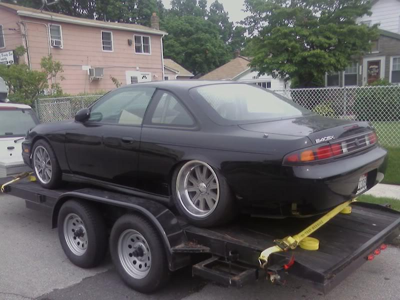
I've moved to Long Island. My little apt doesn't have real garages available... so I rented one in Queens! Here's the beast getting dropped off. You'll notice the rear sitting low because the F'n Ohlins still aren't here (sent out 11/07)! After ordering just basic rebuild parts from Japan without without actually looking at my shocks (wait a few months), then actually ordering specific parts I needed (wait a few months), and now realizing that those specific parts that showed up are different then what I need I'm presuming that I'm going to be waiting a few months.
8/27/08
Called ohlins again today, the cat that used to "take care of" their parts ordering from Japan, no longer works there...
Talked to a nice guy named Christer who has taken his place. They said that they need to order entirely new shock bodies for the rear. I asked them to look into ordering them with the 300zx spindel mounts instead of the 240sx mounts for me. Maybe there will be a silver lining in all of this frustration. (the 300zx spindles are made of Aluminum instead of iron like the 240sx and save you 3.5 (7?) lbs per rear corner) Christer wasn't sure and said he'd get back to me. I'll keep my fingers crossed.
8/29/08
I already rolled the rear fenders. May be even a touch too much as I think I might need a 10mm spacer in back now for the wheel to look completely flush.
I should have stopped here...
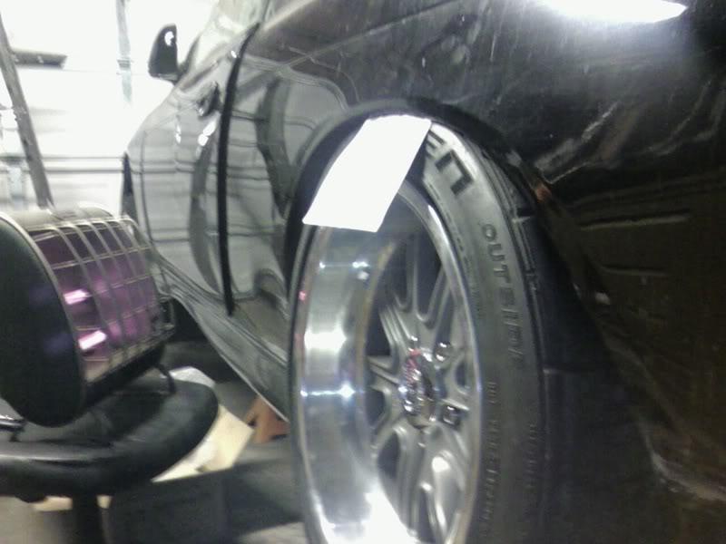
But I pulled it just a tad more. Even though the above looks evil the notion of a rub at 100+ miles per hour didn't sit well with me.
And this just for kicks. AceInHole is running 285s on all four corners! The fronts specifically are 285/30/R18 on 18x10 +20 motegi wheels. I seriously thought that I was pushing the boundries of stock rolled and pulled front steel fenders when I ordered my 17x9 wheels for 255 tires for the front of my car almost two years ago. When I can afford serious brakes that require 18" wheels I will be upgrading to this size tire at some distant point in the future.
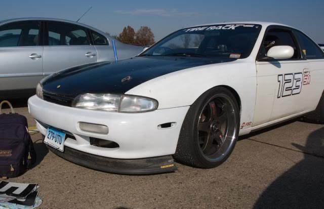
I still think that greater than 285 is possible with stock roll/pulled fenders in the rear though. Once the ohlins are in I'll measure the inside clearance to the coilover and let you all know exactly how much clearance is left.
9/13/08
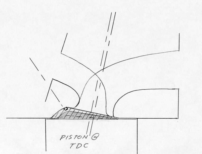
I've been reading up on piston design. I've read a few debates on reverse dome vs. traditional circumferential dish. I was leaning towards a reverse dome when I cam across some writings by Larry Widmer of Endyn.
He has some interesting theories about basically building a reverse dome on the exhaust side of the piston with a regular dome on the intake side of the piston in order to mechanically induce swirl and a better/faster/more localized burn. Even more interesting than his theories are his results! His personal street car is running 13.4:1 compression on 92 octane with VERY little ignition advance (down to 10 degrees), and 300 hp out of 2L with incredibly low BSFC. He originally developed his ideas in the 70s while working on 2 valve nascar heads, though Endyn now seems to specialize parts for N/A hondas.
I've really enjoyed his articles:
The Old One - Energy Dynamics
and here are some pics of his ideas on piston design I pilfered from his web site (I hope he doesn't mind)
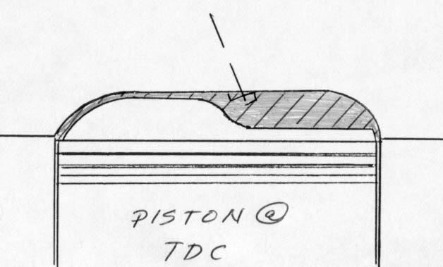
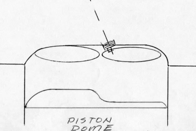
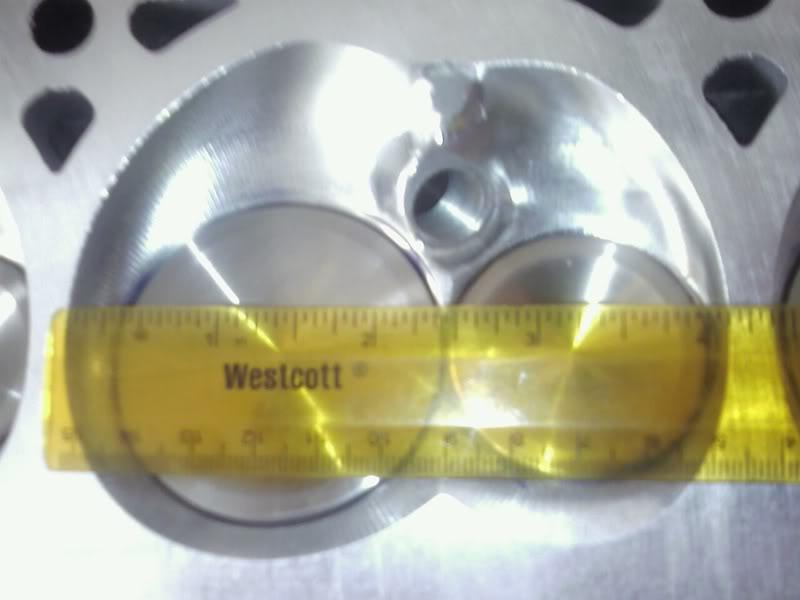
I have a set of stock CNC LS7 heads that have been milled to a 63cc cumbustion chamber
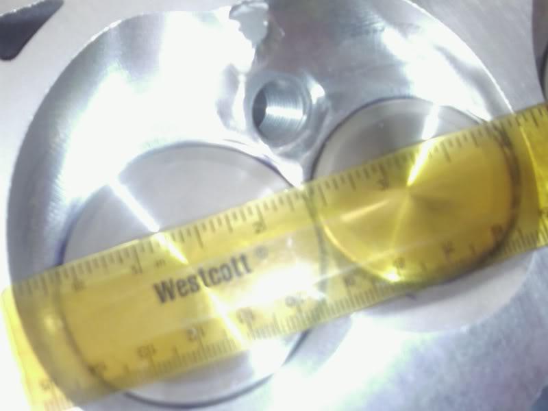
What's up with the funny button of material in the chamber just above the spark plug between the intake and exhaust halves of the chamber? I hope some of the head porters stop by.
With the cam that I am considering now with a IVC of 43.5/68.5 @ .050"/.006" lift I am going to need a dish of about 16cc to keep my DCR below 9. I think that might be a difficult piston to design. Especially for these LS7 heads which seem to have the majority of their chamber volume below the intake (which Mr. Widmer suggests I eliminate with a partial traditional dome; even at the expense of intake valve lift!).
Has anyone tried "soft head" style design on an LS or any other engine?
9/18/08
Thanks for the props guys!
I've been having a lot of fun getting into the nitty gritty of suspension design and engine building with this project.
As much as finishing the project is a major goal, so is learing as much as I can. Someday I'd like to take what I've learned hear and build a one-off, half ton, single seat commuter car. One thing at a time.
I've been following dent sport's build for a long time. I'd like to do a lot of the same type of events as he's doing. Like time attacks and hill climbs. I've printed out red lines rules regarding cage design and other things, as well as nasa's, and while I was at it the NHRAs (all though it seems they will allow most things if they were built to the rules of another sanctioning body).
Check out dent sport's build here
DSG 240RS Updates...still a ways to go
And something else that I would love to do is buy a rally computer and go do a targa with my pops. Oh and Bonneville has always been a dream, maybe the silverstate classic, or maxton here on the east coast. My grandfather used to race a model A at the dry lakes is CA when he was younger than I am, I'd love to do that too. I just want to go have fun and have the fastest car I can build. I've got a lot of dreams!
check out targa Newfoundland here:
Targa Newfoundland - It's About the Drive
-=Peace and Tire Smoke=-
9/19/08
David Vizard had a hand at MTI in the development of their LS7 head porting program. He wrote a short article about it here:
7 Liter Corvette Heads - can they be improved upon? - GoFastNews.com - All Racing News All the Time!

They obviously removed the little pad above the spark plug! If it works for David Vizard...
Also, after not calling me back I called Ohlins again the other day. They don't think that they are going to be able to hook me up with a 300zx style rear-bottom mount even though I need entirely new shock bodies back there! I'm about to change my avatar.
I found my radiator on ebay, although monster motorsports is a good source also. Mine was custom built for Hendricks motorsports for a nascar qualifying car, but never used. Scored it for $260 (they are about $1300 custom/new)... twice because the first one I found UPS threw over my fence and destroyed it. There's only 26-27" between the frame rail which is much more narrow than 90% of the nascar radiators. But we have more room verticly. Also beware of the built in oil to water oil coolers because they will prevent you from putting any angle/v-mount because of frame rail clearance issues. The welds on the C&R are amazing. But beware of superspeedway radiators with >15 fins/sq.in. they may be a little too dense for street use. Mine is 15. Also don't go too thick if you don't need it. 5" thick radiators get pretty heavy once they are full of water.
9/20/08
My garage isn't at my house so it might be a while. But there's a reason for all of the kits sitting so hi. The GTO pan forces the block up, and the tunnel forces the engine/bellhousing forward. Banging is a severe understatement regarding what I did to the trans tunnel to get the engine back, and then I strapped my GTO oil pan down to the mill and took a lot of material out.


it's also subtle to see, but I cut out the ENTIRE center section of the crossmember and reinforced it underneath the steering rack.
The only kit out there that I see right now addressing the oil pan problem is Sikky.
For those interested in N/A power, I asked Brian Nutter of Wiseco Pistons to check out my thread on my latest piston dome idea and here's his response from over on LS1tech.
The soft head concept is valid, but there are some things you need to consider. Larry Widmer is a good friend of mine and a good customer. We do the pistons for his 420+ crank horsepower naturally aspirated Honda 4 cylinders. At the same time, you've got to look at Cup and Pro stock engines today for the most advanced 2v technology. These are the people who know the most, but they aren't going to talk about it on a forum. I've seen the CFD combustion analysis they do and it's incredible. Efficiencies well beyond F1 due to them developing against a standard that remains in place for longer than a couple years. Larry certainly stands as a person that got many of these people to start Studying and Thinking about the art.
Most of the present high end N/A engines do not enhance swirl in the intake port. In general, we don't want swirl at the expense of flow and tumble designs are better. To this end, Larry has some interesting features in the Venturi area that act as a vortex generator and induces the air to stick around the short turn of the intake runner.
Where swirl can be accomplished without hurting flow is in the combustion chamber. A Pro Stock engine COULD use a smaller chamber and get a flat top to net the needed compression, but they don't. What does that tell you about mixture motion? We build up dome around the intake side without shrouding the valve (made easier by the cant of the intake valve used on those heads, and the exhaust side of the dome is smaller-but still above the deck a fair amount. I'd say this area is "funnel like" in the chamber and the dome that matches it.
For guys that are truly gluttons for punishment, we've built pistons that had a dome on the intake side and a Reverse dome on the exhaust. It was a nightmare to engineer, machine, and I hope the customer had an easier time of getting it into the engine than we did building them. The pistons were VERY heavy because of the Mass could not be removed underneath the intake side, yet the crown had to be thick enough under the reverse dome side. All in all, it's an excellent exercise, but the heads and pistons almost need to be designed around each other from the start to not shrowd the valves.
So what's a guy to do?: You'll find the easiest way to get good results is to mill the heads enough that a small reverse dome is necessary. Be careful because you CAN hurt flow and that almost always hurts more than the enhanced combustion helps. Speak to your cylinder head manufacturer as the best have flowed the heads at different chamber volumes. Back to the reverse dome- The wall created with this reverse image actually reflects the combustion back to the center of the cylinder for a split second longer resulting in a more complete burn. I have seen this in CFD and in burn patterns on pistons. As always, there are other things that can offset the gains...deep valve pockets may require lowering the top ring and creating more crevice area. Where does it stop! It doesn't!
Our three part numbers k462,k463, and k464 use something we call the Wiseco flow dome. When we went to a multifit pocket to accomodate different heads, it made it hard to hit the negative -3cc volume necessary for many applications. We designed a nifty little dome that mirrored the face of the valves on the intake and exhaust...this left a natural flame slot around the plug area. In theory, it may promote flow around the valves when the piston is around tdc. Because the intake dome is larger than the exhaust, it could promote movement toward the exhaust side, but the PERFECT combination would require a cylinderhead and dome be built in conjuction....literally minimal piston to valve clearance and the chamber sized to net the compression ratio in conjuction with the dome. We have some visuals of this if you want to email me at [email protected] . Larry and I have spoken about him doing flow testing with the piston under the cylinder head in the bore fixture and the valves opened up as they would be around tdc with typical camshafts. For now though, it's unproven to help or hurt. Some day I'll retire and mess with this stuff every day. Until then, take anything I say with a grain of salt.
The SBC has a lower deck height than an LS1. The LS1 also has much deeper skirt. And I built my pan with enough clearance for a 4.125" stroke. Most SBCs are only running a 3.5" stroke I believe. So of course they can have the bottom of the pan sitting that much closer to the block, thus allowing the entire engine to sit that much lower.
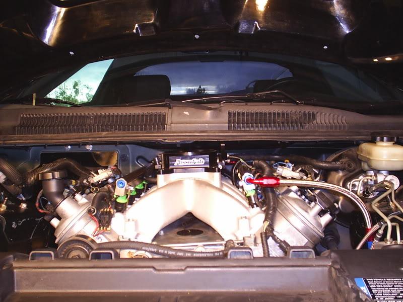
Even with this relatively tall single plane on an LS1 (I'd bet you're intake isn't this tall) you'll notice that the carb base is not taller than the fuel rails.
Also the LSx style plenum under runner intakes aren't as low as you might think. Here's the Al BBK intake for the LS1
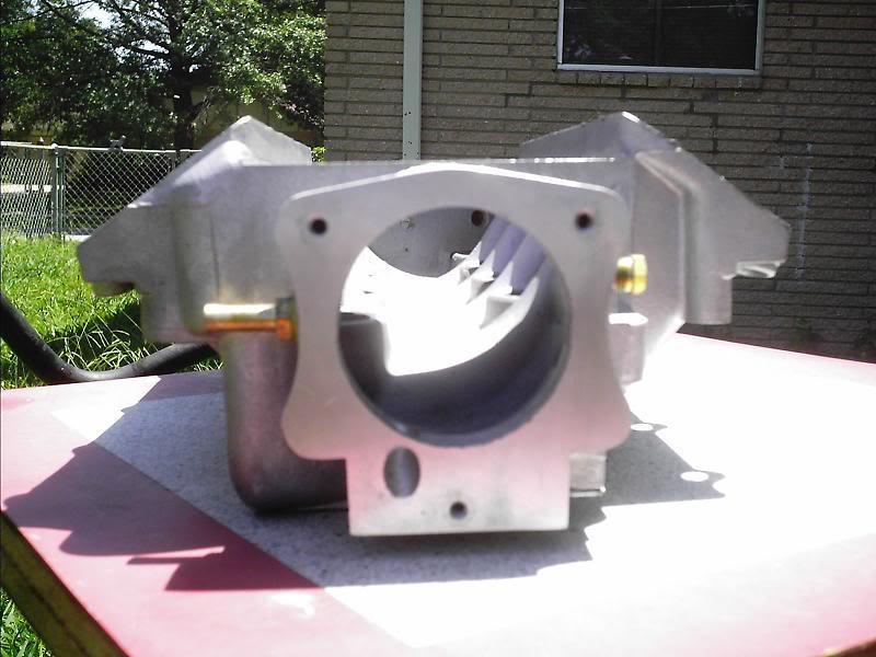
These 4 things together, incrementally, make the LS1 look quite a bit taller than a SBC.
And regarding the fire wall. I really did want to cut it, but that would relegate me to a different class in nasa time trials among others. I believe it also forces you to have a heavier cage in other sanctioning bodies.
11/7/08
I couldn't take driving just the explorer anymore and just bought a '95 miata. Don't worry, though, the LS7 nissan is still the priority. I've been going back and forth with both Katech and Oliver Rods, trying to decide between lube tubes or piston squirters. I got worried about small end lubrication with my dry sump cranking at 15" of vacuum. I'll let you all know which way I go.
I take my last exam for a while next week, and started organizing my new garage yesterday so that I can actually move through it without killing myself. I also couldn't take driving just the explorer anymore and bought a '95 miata. It's equipped with pretty much the entire flyin' miata catalog including the Corky Bell designed whipple "Ubercharger U3". It's currently at 9 lbs and is a lot of fun. I called BEGi last week to ask about upping the boost and how to calculate a projected boost level based upon pulley drive ratio. I ended up speaking to Corky directly for about an hour! It was a real treat. I've read his book "Maximum Boost: Designing, Testing, and Installing Turbocharger Systems" cover-to-cover more than once. He was extremely helpful. He walked me through what turned out to be pretty simple math, and we talked about screw supercharges, and improvements he's thinking about/working on for my kit. It turns out that for a relatively narrow range (that I happen to be operating in), the pressure ratio (aka boost) = the pulley ratio. Flyin' miata reccomends not going over 12 psi on a stock 95 1.8L motor, but Corky said 14-15 is in the range of doable with 93 octane and an excellent tune. To that end Flyin' Miata sold me a very small supercharger pulley (67mm) that they had left over (the stoped selling the kit) at an excellent price because the didn't sell many because they don't recommend them. I also installed an LC1 wide band from innovative motorsports. I plan on polishing up the tune before I swap pulleys. The LC1 and new Link Ecu have not been fun to learn. But I shall overcome, and study, and practice until I am of EFI guru status! Once the street tune is done I'll head over to my old shop in New Jersey, TTP for some dyno sessions and precision alignment. They just moved into a bigger/nicer facility in Little Falls and are having a grand opening BBQ tomarrow, if I can pry myself away from this computer, deny the urge to go play with the link ecu, and get enough studying done tonight I might stop by.
Basically Oliver only makes thick I-beam billet rods. The thickness allows them to use some fancy laser to bore two holes inside the rod lengthwise. The holes supply the small end with oil from the mains. Just like with piston squirters, more oil pressure/volume is probably a good thing.
When running a high vacuum sump pump there is no oil being splashed around lubricating the small end of the rod, and failures sometimes occur.
http://www.flatlanderracing.com/olivertubes.html
12/10/08
The lube tube rods showed up from oliver the other day!
And some news from Ohlins... but first I thought that I'd introduce my lastest distraction

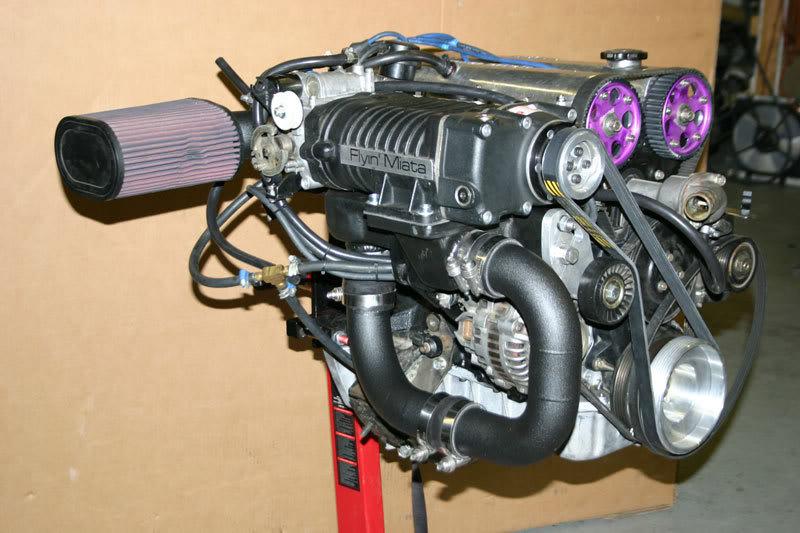
A whipple charged and intercooled 95 miata with 220whp! It's a lot of fun. The second pic is not from mine, just what the kit looks like on a pre '94 with out an intercooler.
Ohlins informed me that they have lost my front shocks, including the tein camber plates, and tender springs. And the custom wooden crate that I spent an entire day making and requested be reused.
Feeling trapped and without a lot of options I asked what they planned to do about it and was informed that they would ship me a new set for $1500 which is supposedly below their cost. I asked if they had the newer DFV valving available and was informed... no. Also something that I have mixed feelings on is that they are steel, not Aluminum. I realize that the retail on these things is $3200, but honestly I don't exactly feel taken care of (at $1500) after a year of being dicked around, and not even getting my parts back.
Am I being unreasonable?
What would you guys do?
1/11/09
Ohlins & Cam Update:
There's a new guy at the North Carolina shop Joey, that's actually been calling me back when he says he will. He told me that he recently found my front shocks, but that the tenders, springs and camber plates weren't there (in a storage closet). He called to tell me that my new set is in from Japan finally and he'll try and find the rest of the parts. I told him I want everything back, so he's going to do his best. He's holding firm on the $1500 ($3200 is retail) stating that is below their cost. I have trouble believing that, but I'm not going to call him a liar.
So every thing should be back in my hands by February!
And I'll be putting my original Ohlins up for sale with full disclosure to what ever brave soul wants 'em for $500, when I get 'em.
I've been farting around looking at the most popular LS7 cams and comparing them to what I've been spec'n. Here's what I've gathered about the QM600 & Katech's Torquer:
QM600
Specs:113+X 23X/25X 6XX/6XX (14-24.5 overlap @ .050â€Â)
Carlos from Vette-Air, “QM600 cam have made everyone pretty happy. With bolt-ons and tuning you are looking at 545 to 565 and with ported heads 575to 600 on pump gas!!!â€Â
Peaks at 6500 with very little taper
600.3 RWHP / 534.2 Torque (RPM ported heads)
598 HP / 529 TQ (WCCH ported heads and bolt ons)
564RWHP / 501RWTQ bolt ons
Stock Dyno: 432 rwhp /419 rwtq
Bolt Ons & Tune: 490 / 462
QM600: 555.6 / 485.5
542rwhp and 485 ft-lbs (with only 24 peak timing)
542RWHP 482RWTQ w bolt ons 91 oct (baseline stock was 448 hp though)
Katech Torquer LS7 cam
Specs: 220/244 .615.648 110lsa (usually +4)
(12 overlap @ .050â€Â) From 0 to 4 degrees advance: It increases torque about 6 lb-ft and sacrifices about 4hp
very drivable at 1500rpm in 6th peaks at 6500 rpm. Katech considers it a trade-off for drivability for a loss of power above 6000 rpm. Peaks at ~6400
06 Z06 makes about 500rwhp on a Mustang.
Depending on whose chassis dyno, we have seen 508-557rwhp
And exactly 600hp / 570 lb-ft of torque on an engine dyno.
In judging the aggressiveness of a cam I often look at the overlap first, and the qm600 definitely carries more overlap than the Torquer, despite the wider LSA. It's surprising to me that the qm600 doesn't seem to produce much more upstairs if any!? With both of these cams, it appears no one's made >565 whp without porting the heads on a 427cc LS7.
The cam I'm spec'n right now changes weekly, but for comparisons sake here's what I like today: 236/244 110 +4
If you use David Vizard's chart to determine LSA based on a ratio of discplacement to intake valve area, he states that the ideal LSA of an LS7 would be 108. I think that the LS7 can probably get away with a little bit wider of an LSA due to it's exceptional flow qualities, especially compared to the SBC heads that I believe David's chart was intended for.
Let's compare LSAs:
Vizard's Chart: 108
Mine:110
Katech:110
qm600:113
stock LS7: 120.5
Also from Vizard's Article:
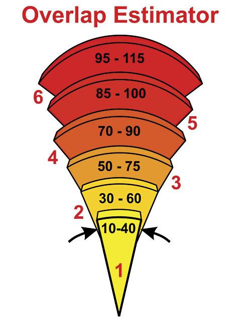
Level 4 is considered the "street/strip" range of overlap given in "advertised" duration (~0.006" of lift). But once again, I think that for the LS7, these values need to be shifted a little more conservatively.
Let's compare the overlaps @ .050" lift
mine: 20 (69 @ 0.006)
qm600: 14-24.5
torquer: 12
stock LS7: -20
Per Vizard's chart (via overlap alone) my cam is so mild that it doesn't even qualify as a street strip cam! And the Torquer (and probably the qm600) is/are even more mild still. Katech has some videos on you tube of a c6 lugging along on the freeway at 52 mph in 6th gear @ ~1500 rpm. This mild overlap is probably part of the reason these cams are touted as being so "driveable".
Let's compare IVC ABDC @ .050" lift
mine:44 (68.5 @ 0.006)
qm600: ~44- ~52.5
torquer: 36-40
stock LS7: 42 (~66.5 @ 0.006)
I'm used to looking at LS1/LS2 cam numbers, and when I first sat down to spec out my own cam I thought that I had an extremely late IVC. For reference: Patrick G once said IVC no later than 46 (maybe 48?) on a 346 w/ 241 heads. I also presumed that the stock LS7 cam would never have a late IVC with its smallish 211 intake duration. But, interestingly, it's massive LSA of 120.5 pushes the IVC within 2 degrees of my cam! Even more interesting, you'll notice that Katech's cam has an IVC even earlier than the stock LS7 cam! So that's why they call it the TORQUER! Installing that cam, has the same effect upon your dynamic compression ratio, as milling the heads!
Re: future changes?
Before this is over, I may add a touch more exhaust duration, and reduce the advance. I don't know, we'll see!
One more thing I just noticed:
Katech's torquer cam raised the LS7s DCR from 8.5 to 9.1!
And this is still on pump gas! Wow. That goes a long way towards illustrating how good the quench and heat dissapating properties of the LS7 are engineered. A lot of the engine masters challenge engines seem to run with a DCR of right about 8.5. Very few people claim to run around on pump gas on the street with a DCR >9.0:1.
1/14/09
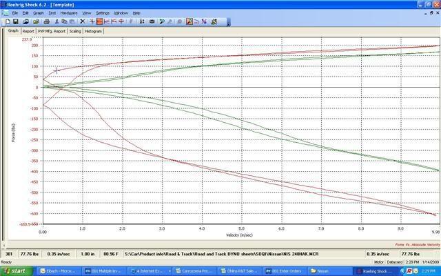
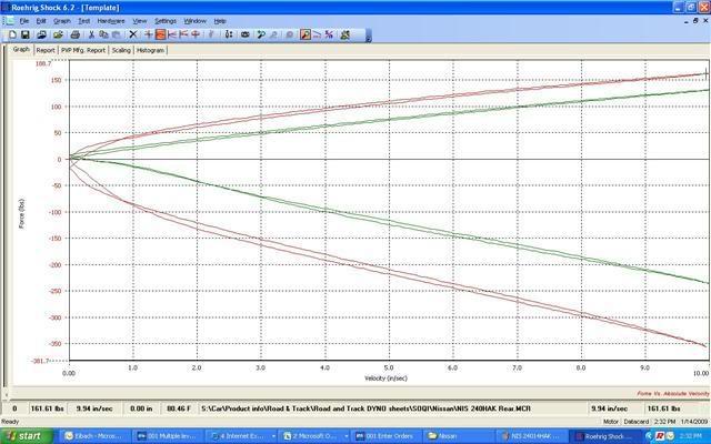
I spoke to Joey at Ohlins USA again today. Here are the Shock dynos from my new coil overs. He told me that they put 'em up on the dyno when they first go in because they had never seen these before in person, and were wondering what they would do.
There are runs for both rebound and compression at full soft and full hard (thus the 4 lines per graph). I'm hoping to get a dyno graph at each seperate setting for each corner later, mostly to just match the dampers left to right. Ohlins assures me that they will be the same L2R, but I'll believe it when I'm holding the graphs in my own hands. I'll shoot some PMs to those that know more about reading these than me and we'll all see what we can learn.
Fronts:
Rears:
1/15/09
Tim,
What exactly are CVP files? Will I need a special program to read them? If you click on the pictures above they get a little bigger, at least enough to read the velocity and force axis numbers. Lemme know I can call Ohlins later today.
David,
I was half joking when I made that post, and I've always loved the lay out of the s2000 no doubt. Matter of fact the s2000 is set up a lot like an old 240z. But if you want to get technical, it's safe to say that my engine's cg is behind where a front axle would be, so... It's all semantics, regardless, these things rotate great when all is said and done. And even with my monster radiator I'm hoping to have <53% of the weight on the front when complete. We'll see!
That post was actually a copy of a post I made for MMDB's LS1tech thread about his LS1/240sx build
My 240sx / S14 LS1 Swap - Progress *56k beware* - LS1TECH
MMDB post 264: "Update: It's been bout a year since I've completed this swap. The swap has proven to be very rewarding reason being I haven't had the engine fail on me and I've been able to have fun with the car almost every day going to and from work (30 miles each way) and more. What I want to bring up now is handling. GIGPUNK's post (261) illustrates the position of the motor within the chassis, which leads to a few things. First off, the t-56 being heavier allows the 240 to rotate much more. This could be good, and this could be bad.
In my case I was running 11kg / 9kg spring rates front and back respectively, which proved to be TOO stiff! This was bad. The car found itself difficult to plant the rear tires under acceleration. During corner exit as well, the car wanted to slide out.
What is good is that the car WANTS to rotate. But with such high spring rates it's difficult to put down the power and the car just wanted to slide whenever applied.
To counteract the negative affects of oversteer and prevent it I dropped the rear spring rates from 9kg to 6kg, and dropped the front from 11kg to 9kg. I also lessened the rebound dampening (my shocks do both rebound and compression) which allowed for smoother weight transfer during mid-corner to corner-exit transition. Removing the sway bar in the rear helped a lot as well (basically a sway bar increases spring rates during lateral weight transfer).
I thought this post might help whom ever is battling this issue and wants more grip. Of course there's many other ways to tune the suspension such as running a bigger sway bar up front, but for my purposes changing spring rates was more convenient for me. "
You'll also notice that Wikipedia lists my car as being FMR
Mid-engine design - Wikipedia, the free encyclopedia
Oh I bust me up.
1/20/09
Backspace & frontspace!!!
This is a repost from one I made for the max rubber thread:
I think the reason that this topic seems so hard to nail down is that there are really two dimensions to a wheel that you need to know on a 240sx, one objective, one subjective.
The objective measurement is the distance from the hub face till you hit something on the inside (like a control arm or the strut). This is also referred to as BACKSPACE. This distance really doesn't change much, even between s13 and s14. Sure an 18" wheel may have a bit more clearance than a 16" wheel to the control arm, and 5* camber may get you in more trouble with your strut before 1.5* will. But for the most part, this number doesn't change, and is what we should be comparing!
The subjective measurement is the distance from the hub to the outside of the wheel. I've never seen this distance labeled on a wheel diagram, so I'm going to call it FRONTSPACE. This is the only thing that should be changing depending on overfenders, stretch, monster rubber/buldge, S13 vs. S14, roll, pull, etc. I find FRONTSPACE to be a matter of taste, as such it should be calculated from proper measurements and good wheel/tire size with accompaning pictures as have been provided in this thread already. Bust out the calculator people!
Once you know what the max backspace IS, and what frontspace you WANT: bust out the calculator again, and you've got your max wheel.
Almost all of these pictures and descriptions were pilfered from this thread. I'll break em up by front and back, because I'm trying to define max backspace per end with this post.
FRONT
backspace 153mm
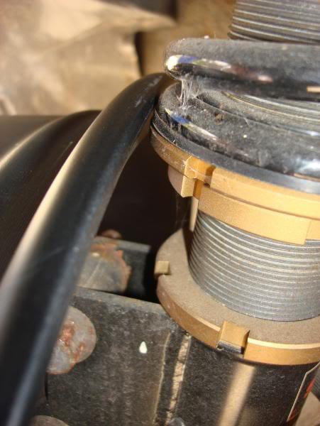
I think that this first picture is the most helpful. Yes the wheel is hitting the strut at exactly 153mm, but it wouldn't be with shorter springs/taller ride height/small spacer.
backspace 157mm

backspace 149mm
backspace 157
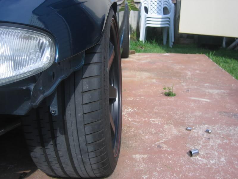
backspace 159
REAR:
backspace 172mm
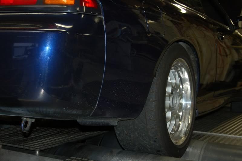
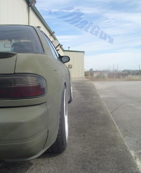
yall may not be impressed by this cat's "flushness", but the sucker goes deep!& those are 275s (on 17x9.5 +39), look how much room there is on the frontface still, and those fenders don't even look rolled! This echoes my earlier post that there is no excuse for an s14 to be rolling around on anything <275s in the rear.
backspace 173mm
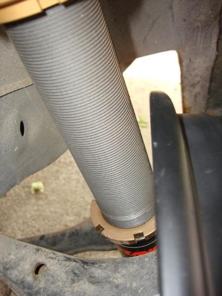
Again one of the most helpful pictures that our fellow zilvians have bestowed upon us! Basically this tells you that unless you're running skinny ass stock type dampers, or relocate your rear damper, that you will NEVER get much deeper than a 178mm backspace!
proving my backspace is universal idea here's a couple s13 pushing the limits:
backspace 173mm

backspace 174mm
Putting this together took a bit of work, but we now have half the equation.
MAX backspace Front~ 150-159mm
MAX backspace Rear~ 172-179mm
Calculate the backspace, of a zero offset wheel by multiplying your rim width in inches by 12.7mm/in
9in x 12.7 = 114.3mm
Add that number to your current offset to get your wheel's actual backspace.
114.3 + 22 = 136.3 mm
subtract your back space from the theoretical max posted above to see how much clearance you currently have on the inside. or just get under your car and measure it with a ruler/caliper. I predict you'd find these clearances if you did so. Let me know if you find different.
rear 172-136.3= 35.7mm
front 150-136.3= 13.7mm
1/23/09
I went crazy and figured out the max wheel/tire that could be put under a 240sx. There have been a million posts asking, "will this wheel/tire fit?" Now you know.
MAX backspace (Same for s13 and s14)
Front~ 150-159mm
Rear~ 172-179mm
MAX Frontspace [backspace + frontspace = wheel width in mm]
S13 Front 95-105 (looks great at 99)
S13 Rear 80-95
S14 Front 109-116
S14 Rear 97-117 (110 really is perfect with a good r+p)
I also downloaded the Roehrig shock/spring dyno software and thought the displacement graphs might be helpful to some in addition to the above (post 155) velocity graphs.
front

rear
I think it's interesting (and probably most usefull) that the adjusters only significantly affect the low speed damping. The small change they make in high speed is one of the few faults I can see in the ohlins; at high speed the adjusters actually do the opposite of what they are supposed to, but to such a small degree (percentage) that I don't think it is significant. Anyone disagree?
1/28/09
I'd like to share with all of you a quote from my chief of surgery, "Are you functionally retarded?"
That's all I have to say about that...
In other news, here's some new pics:
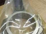
The Oliver rods came back. Oliver is a class act! Every rod came back cleaned, oiled, and with each rod individually sealed in a heavy duty clear bag. Here's a pic of the recently added lube tubes.
To the front face of the block was 14.125" behind the core support. I think that distance would be a little bit more in an s13. Also notice how rust/battery box free my engine bay is! Drilling that tray out was not fun!
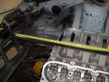
I was asked to quantify my blocks placement so here ya go. Looks like a little less than 7" from the top of the block to the seam. With a 2" cowl I'd have a whole foot of clearance!
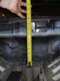
At the front/top edge of the block I currently have 8" to the bottom of the hood. This high mount alt actually fits! But my GTO alternator is too big for the f-body alt bracket, so custom mount to the lower, driver side motor plate is coming up. Anyone need a billet, passenger side alternator hi mount for (I was told) a vette offset?
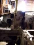
Hey guys I'm trying to figure out the length of the spacers that I need to mount the alternator to the motorplates. I measured the above alternator mount that I randomly got on ebay and will not be using. It puts the inside of the belt exactly 4" from the front of the block. Anyone know if that is F-body or Y-body offset?
I finally paid for the ohlins today, it looks like they really did loose my rsr springs, tender springs, tein camber plates, and custom heavy duty crate. They are going to give me some new tender springs as I was planning on using them on the miata, and they knocked another $100 off the price. That won't exactly cover another set of camber plates and springs, but it's time to cut and run.
And this is bitchin: Active aerodynamics for your track day car!
http://aeromotions.com/gallery/
I also have gotten tired of running to home depot to not find the bolts that I need and am thinking of getting a monster/complete set of nuts and bolts from Fastenal
3850 Pieces Asst. Bolts Nuts and Washers M4 to M12 | Fastenal
I've also been sourcing endlinks and threaded hex rod so stay tuned for some custom sway bar endlinks and home made adjustable suspension arms; part numbers to be included!
3/5/09
Ohlins showed up today. Here's some pics of the parts and part numbers.
Looks pretty fancy http://www.carrozzeriajapan.co.jp/ohlins/4w/pcv.html

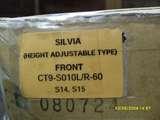
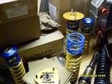
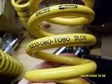
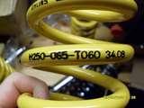
I can't make sense of these Germen sourced Eibach/Federn spring codes that came with the camber plates and helper springs.
I'm pretty sure the rears are 2.5"/65mm ID x 10" tall 6kg, and the fronts are 60mm ID x 8" tall 8kg.
And just when I thought my ohlins were expensive:
http://performanceshock.com/index.ph...roducts_id=807
and
http://performanceshock.com/index.ph...roducts_id=561
no more complainig.
3/6/09
The same thing happened when I priced out aurora bearings for my sway bar end links. Not even using the high-mis-alignment stuff the price came to about $37 per corner.
AW6 3/8_24 female steel rod end $15 x2
Steel jack screw at midwest control products $1.62
Aluminum spacers and grade 8 bolts $5
It turns out mazdaspeed sell the same thing for $39.
I ended up just ordering the mazdaspeed ones from goodwin racing to save myself the time of sourcing the spacers, nuts and bolts. I also ordered some extra boot protectors from seals-it that I'm going to fill with some synthetic brake caliper grease just for corrosion protection.
Seals-It
Even though the US economy has seen better days, it seams that most the rest of the world is doing a little bit worse. We are doing pretty damn well against both the yen and pound, which makes these a pretty damn good deal:
Driftworks Lower Arm Front And Rear S13 S14 S15 R32 R33 R34
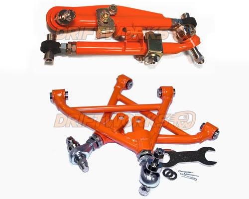
With current exchange rates these come out to about $615 before shipping for all four corners! I'm pretty sure these are what Bill from DSG is running in the front, and these guys have an excellent reputation in Europe. Plus, then you don't have to actually do any work, or make any delrin bearings.
3/11/09
I got the mazdaspeed ball-end, sway-bar, endlinks and am a little dissapointed. Originally I priced out low offset aurora ptfe lined female ball ends with male jackscrews that came out to about $35 bucks. But I didn't want to bother figuring out what size spacers I would need, and tracking down the hardware. I've never read a bad review of the mazdaspeed miata endlinks and at $39/corner thought they were a good deal.
These are some cheap ass endlinks
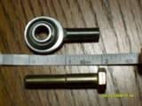
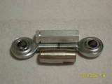
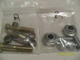
Both the front and rear parts use the same spacers, ball-ends, jam nuts, and bolts. But the rears use a slightly shorter steel turnbuckle vs the fronts loosely threaded aluminum hexlink. Both for the fit and finish and for the couple extra mm shorter adjustment range I'd order 4 rears and use them on the front too.
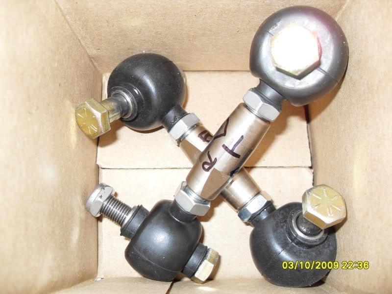
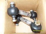
The ball-ends are really loose, unlike quality ptfe lined ball-ends, and there is probably a thousandsth or so of play in them.
I used Seal-it rubber boots to protect them and filled 'em with a little synthetic brake grease. The Seal-it boots are a quality product. But seem a bit pricey at $5 apiece. It's a bit of a puzzle to get them on the first time, but the rubber is super tuff stuff. Just grab some plyers and go to work. I'm just going to keep my fingers crossed, and hope that they last a while. Hopefully the boots will buy me some time.
3/14/09
from post 170
MAX backspace Front~ 150-159mm
MAX backspace Rear~ 172-179mm
When I made these determinations
I was taking advertized wheel widths, deviding by 2, and adding the advertized offset to calculate backspace. As cnichols recently pointed out to me, that only gets you the backspace to the inside of the inner lip! True backspace is to the outside of the wheel, not the inside of the lip that holds the tire.
This picture should help explain:
This is a pic of my rear wheels 17x10.5 +27.
Using my previous calculations would yield a back space of
(10.5x25.4)/2 + 27 = 160.35 mm
which is 13.65mm off from the actual measured backspace of 174mm
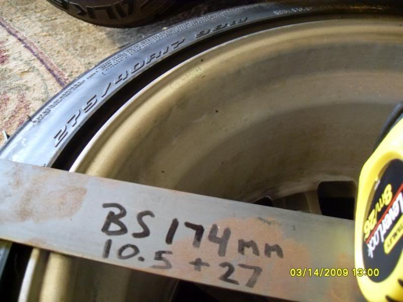
So how well does a 174mm backspace 17" wheel fit the rear of an s14?
My new Ohlins shock body is 49.7mm in diameter and sits exactly 13mm from the above wheel.
And 22.8mm from the front edge of the lower control arm
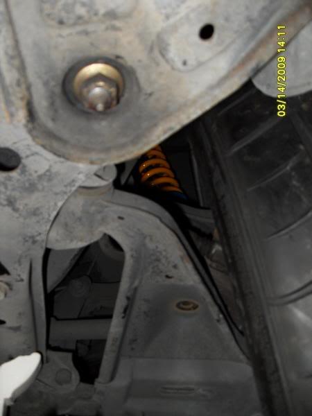
and no clearance issues to the rear
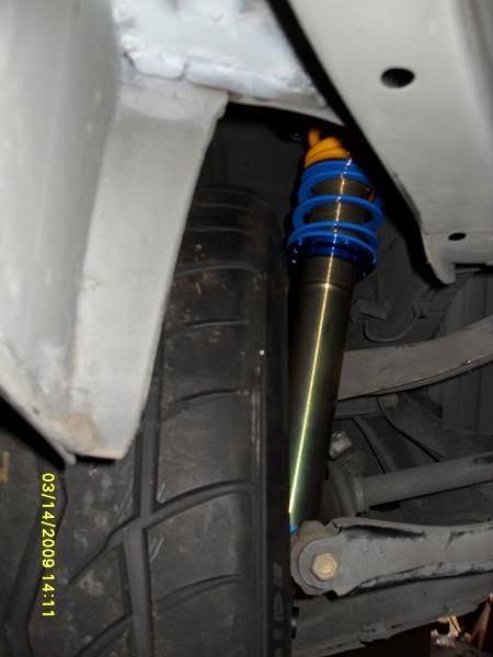
With the coilovers up high no problem
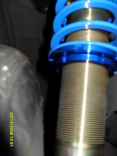
With them low... uh...
sill clears, but...
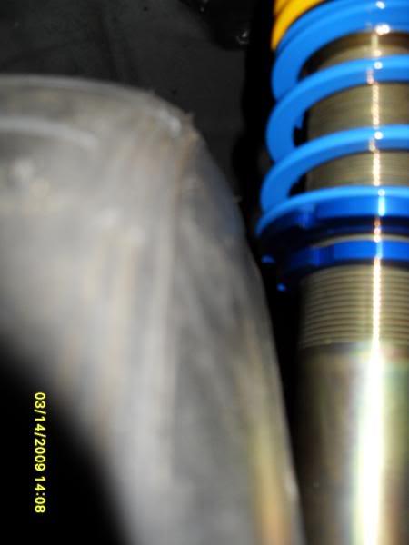
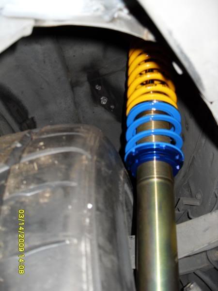
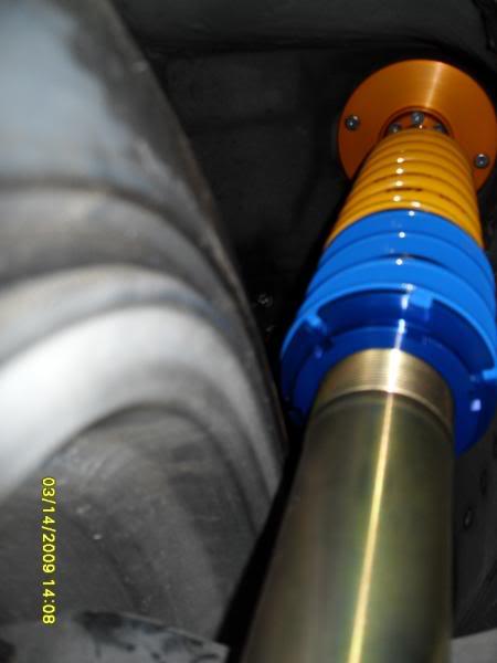
So if you're about to order a new set of custom CCW wheels what backspace to you ask for? Less than 174+13= 187 (7.362")
Max Frontspace with stock fenders: (calculated using my old method)
S13 Front 95-105 (thatguy looks great at 99)
S13 Rear 80-95
S14 Front 109-116
S14 Rear 97-117 (107 really is perfect with a good r+p)
So far I've only done the roll and pull on my drivers side rear fender.
I took this measurement directly below the back edge of the rear window.
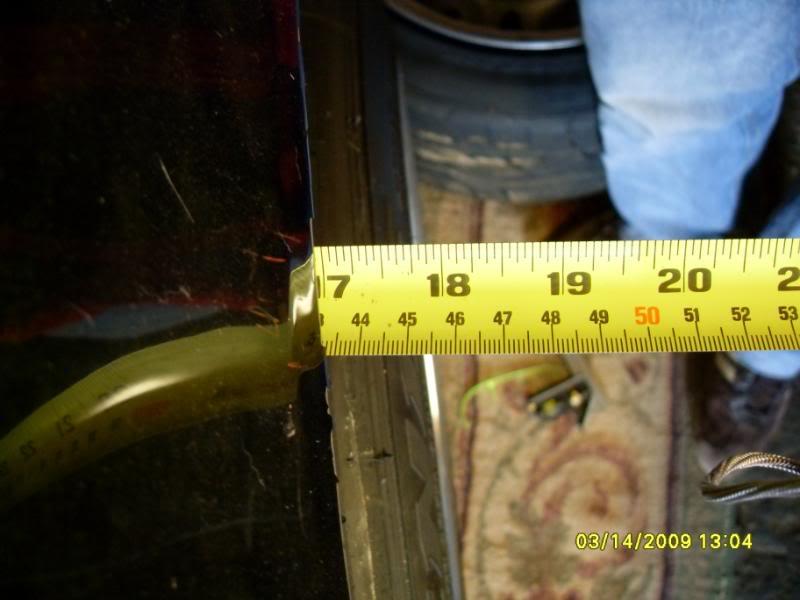
Looks like my R+P gave me an extra 38mm over stock. Presuming both sides have the same depth of well. And It damn near looks stock too!
Stock Passenger Side
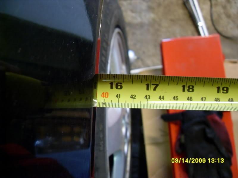
My current front space, from hub face to outer tire edge is
(25.4x10.5)/2 - 27 = 106.35mm
I probably could use a 10mm spacer and still be fine with my fender clearance, but I doubt that I could pull the fender much more without it looking weird.
So lets call it a max frontspace of 115mm and a max backspace (only to the outertire edge) of 170mm would yield a wheel 285mm (11.22"). If you go any bigger you're going to have to do something drastic to your fenders. Also, to pull this off, your coils will probably have to sit higher than the tire.
I would really like to own the redline time-attack street class some day. The current rules only allow tires upto 285s, and forbid inboard/cantilevered dampers. I think that a 11.22" wheel would be perfect for 285/30/18 tires. Personally I'd order up four of them all with the same <7.362" backspace and just use whatever spacer and fenders are necessary in the front.
I've also been hunting for an inexpensive cast wheel that that would come as close as possible to this. I was looking at the rpf1, but it only comes in +15 (wasting a lot of space). The knock off ford wheels come in 18x10 +27 but I've heard that they weigh 31lbs! The closest thing that I've found so far are the 18x10.5 +30 Enkei nto3+m; they weigh less than 22lbs and cost around $350 a piece.
4/18/09
Builds been on a slight hold while I'm preparing for a liscensing exam. But yesterday I went with my girl to this really nice seafood restaurant here in Long Island. It's finally crested 69 degrees here in the NE, and we took the miata with it's supercharger and Link fuel management computer. The valets were standing there but I just parked my self anyway. And as we were walking into the restaurant they were kinda pushy about getting my keys. So I finally just handed the Dick my keys not wanting to make a scene, for my girls sake. The aftermarket ECU surges a bit, doesn't like light throttle, and requires ~30 seconds of waiting in the accesory position to turn on, prime the fuel pump, and sync the cam and crank angle sensors, before it will let you ignite the engine.
We had a great dinner and when we came out instead of getting bent out of shape, I just handed the Dick my valet stub, then whispered to my girl, "Watch this, this is going to be funny." Of course the Dick couldn't get it started, my little miata is parked between some $100k Mercedes and Jaguar turning over and over. We both laughed as the Dick came back with his head held low and handed me back my keys without looking me in the eyes. Then we hopped in the car, and because I waited the requisit time before turning it over, it started instantly. All the valets were watching as it started right up, and with a little creative clutching pulled out as though it was dead stock. As I drove past the Dick I said, "There was a reason I didn't want to give you my keys." My girl thought that was a good show.
4/24/09
Well I'm mad cash strapped until I get a job after I graduate in June, so I put some parts up for sale on e bay. The Ohlins are up for sale if you think you're crafty and can get them back together with a reserve of $100. I'm probably also going to list my black billet hi mount alternator bracket, and c5 throttle peddle with TAC.
eBay Motors: Ohlins Nissan 240sx coilovers S14 JDM silvia springs (item 130302376520 end time May-01-09 13:54:26 PDT)
I also rolled out to the weekly car gathering in the parking lot of Best Buy in Woodbury last night. I couldn't believe how many guys rolled out there. Good time, smelled like gas and burn outs.
5/19/09
So I'm starting at the back.
So I left my stock s14 fuel tank back in CA when I moved to the East Coast. It's actually a pretty good design and if it was still here I'd probably use it. Most of the stock tanks volume sits above the diff between the rear shock towers, then has two legs that go forward and below the rear seats on either side of the drive shaft.
My idea is to try and get the weight of the tank a bit lower and further back. I also want to build my own rear diffuser. So originally I was thinking of cutting out the bottom of the trunk, and making a custom aluminum tank whose bottom doubled as the majority of the diffuser.
My dad was pointing out that aluminum tanks should probably be rubber mounted to reduce the likelyhood of fatigue cracks which Aluminum is susceptible to. Anyone have any experience with aluminum gas tanks?
So what does a fuel tank have to do with the exhaust? Well with the sides of the drive shaft space open there is extra room for my expansion chamber and cats.
From Random Technologies Website: "...a 3" diameter 7000 series SuperStainless catalytic converter flows 617 cfm. Most 3" diameter high performance mufflers flow less than 475 cfm at the same test pressure."
I also found these test results where 2.5" aftermarket cats were tested and compared to stock LS1 f-body cats.
Table 1
CFM @ 20.4â€Â H2O
CFM @ 28â€Â H2O
Passenger Side Catalytic Converter
299.5
350.9
Driver's Side Catalytic Converter
268.3
314.4
TTS Bullet Catalytic Converter
277.1
324.6
Carsound Catalytic Converter
372.7
436.7
FLP Catalytic Converter
376.0
440.5
First a word on CFM flow rates. Heads are usually flowed at 28â€Â H2O, while carburetors are usually rated at 20.4â€Â H2O, and my hero David Vizard rates exhaust flow CFM at 20.4â€Â H2O. By the looks of things Random Technologies rates their cats at 28â€Â H2O.
But why care about cats on a 700hp v8? Redline time attack street class rules, that's why. Oh and they are way more restrictive than you might think.
David Vizard’s research shows that 2.2 cfm of flow at 20.4â€Â of H2O will support 1 horsepower. 2.2 cfm is the optimum flow through the exhaust keeps horsepower losses under one percent.1 Removing the stock catalytic converters on the LS1 usually results in a gain of 8 rear wheel horsepower.
FLP or Carsound = 373cfm
373/2.2= 170 hp per cat (w/ 2.5â€Â i/o)
Random Technology 3" diameter 7000 = 617 cfm (probably 524 cfm @ 20.5" H20)
524/2.2= 238 hp per cat
Now it should be a little more clear.
If you're rolling a single cat, you have a restriction if you're making over 170-240hp, regardless of which fancy pants stainless "race" cat you're running! Bogus!
This also means that if I'm running FLP aftermarket race cats that I would need 4 (3 if I ran the randoms) of them in parallel to build a truely free flowing exhaust! I've never seen anyone run cats in parallel. The reason for this is either cost, space, or you can't get enough heat into them. I dunno.
To make sure that street class participants aren't running gutted cats, redline states that they will use infraread thermometers to make sure that your cats are lighting off.
more from random technologies web site: "...Under normal operating conditions, the catalytic process doesn’t begin until temperatures inside a converter reach 500 to 600 degrees (F). If air/fuel ratio is on target, and the exhaust is free of contaminants, internal converter temperature stays at about 1200 degrees. But when unburned fuel enters the picture, temperatures can reach 2200 degrees and either burn the precious metals out of the washcoat, or literally cause a melt down of the bricks."
So now the real question is: will three or four parallel cats get up to temperature if they are sitting five feet from the heads with an expansion chamber between them? By definition anything richer than 14.7 will have "unburned fuel". And considering my car will be running richer than 13:1 most of the time, maybe the extra exhaust temps will actually be useful? Redline doesn't say when them test your cats temps. I'm pretty sure I'd be ok after a hot run.
This is getting too long, but here are some pics of preliminary measurements for the rear diffuser/new fuel tank area, and I'll talk about expansion chamber design another day.
This is a pic of a one inch piece of steel stuck to the bottom of the subframe. The piece of steel creates two rectangular spaces about 3"x5" on either side of the diff. Should be enough for four 2.5" exhaust pipes.
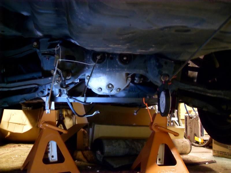
would four 2.5" exhaust pipes flow enough for 700hp?
Check this out:
A section of straight pipe the length of a typical muffler, rated at the same test pressure as a carb (1.5â€Â of mercury= 20.4â€Â H2O), flows about 115 cfm per square inch.
open horsepower
pipe supported w/
size single pipe
2.0â€Â D = 3.1 A X 155/2.2 = 218 HP (x4=872 HP, probably a better idea)
2.5â€Â D = 4.9 A X 155/2.2 = 345 HP (x4=1380 HP, yeah should be ok)
3.0â€Â D = 7.1 A X 155/2.2 = 500 HP
3.5â€Â D = 9.6 A X 155/2.2 = 676 HP
4.0â€Â D = 12.6 A X 155/2.2 = 887 HP
Proof Hondas with 4" mufflers are built by assholes.
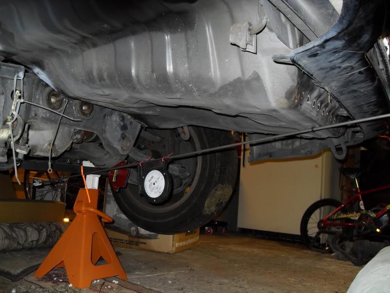
It seems that diffusers can sit anywhere from 4-14 degrees. Less than 7 degrees to prevent flow seperation/drag unless of course you have a massive wing within a verticle foot for interaction like F1.
So I just took a look at the revised 2009 Redline time attack rule book and it looks like full undertrays are now allowed in street class. The wording on the fuel cell rules is a little strange:
"1.6.4 Fuel Cells permitted (modification of factory floor pan is allowed for installation of
Fuel Cell)
1.6.4.1 Good quality fuel cells contain a bladder constructed of Nylon or Dacron
woven fabric impregnated and coated with a fuel resistant elastomer and
are FIA FT-3 (or higher) rated.
1.6.4.2 The cell should be in a container made of at least 0.036-inch steel, 0.059-inch
aluminum, or 0.125-inch Marlex, fully surrounding the bladder.
1.6.4.3 Foam internal baffling is required, as per FIA FT3-1999 (or higher)."
So it says that fuel cells are permitted, then it goes on to define a good one as one with a bladder. It doesn't seem to expressly require a bladder within the cell though. The rules also seem to say that there "should" be a container for the bladder. Does should = required? Or am I just seeing what I want?
Bladders are around a $1000. I was hoping to get the car on the road without one, with just a custom aluminum fuel tank, then add a custom bladder to it way down the line.
How do you guys interpret the above?
7/9/09
Headers:
I'm going back and fourth between three options:
1. I found these guys Custom Headers Built To Your Specifications
they have a neat idea, they send you mock up kit, you position all the tubes where you want them and mail it back. All said and done in stainless for $1300+s&h with merge collectors. Plus the fact that they purge weld the headers is pretty bad ass.
2. But then I also have an old set of plain steel headers that some guy had for an OLD gm F or B body LS1 swap. They do not fit at all, but I scored them for $100 and figured they'd make a good starting point with the flanges at least. Plain steel headers always seemed like a waste of money to me. I don't care what you coat/paint/wrap them in they will be rusty within a year. Rust isn't the end of the world, but in a car that gets used rain or shine I don't think steel headers last much more than 6-7 years. It would take probably another couple hundred in j bends and collectors to make them.
3. My third option is to just drop the car off at Kooks or American Racing Headers here in Long Island. MINIMUM of $1500, and I'd have the least control over where the collectors end up.
Also, does anybody have any software to help determine tri-y vs 4 into 1, and primary and collector lengths?
7/13/09
So it looks like Kooks is way down in NC now. I called the guys at American racing headers, in nearby Amityville Long Island. They were very cool and said that I could come down and try any of their LS headers (they make like 10 different ones) to see what is closest. And if nothing quite came close enough they could do a total custom job in 5 days for around $2500. That is about the going rate these days. While it's a lot of money. Five days of a professionals time costs. This is a bit of a DIY project though and right now I'm leaning in other directions.
I'm going to do a little multi post series on header design, starting today with choice of materials:
You basically have two choices. Stainless or Plain steel. Most people think that the only advantage plain steel has over stainless is cost (almost %50), but they are wrong! Plain steel is also a bit lighter than stainless! Even given these two advantages I’ve always thought that making headers out of plain steel was a waste of time and money, mainly because plain steel headers rust like motherfuckers. Some would say, “well then just coat it.â€Â
When I was woking at TTP back in Jersey on all the hi dollar LS1 cars, I was lucky enough to become the header bitch. I swapped out a lot of headers! And I don’t care what coating was used ( I saw at least 4 different kinds), rust was visible through the coatings with in a year! Bogus.
“Ok don’t coat it then, wrap itâ€Â you say. While I have to admit that I love the old school hot rod look of fiberglass header wrap, it’s murder on steel headers. It basically acts like a big sponge soaking up whatever oil and water comes its way, and then holding it against the header. Can you say instant rust? While header wrap will reduce under-hood temperatures and improve looks, it also shortens the life of your already ‘livin on borrowed time’ plain steel headers.
Now if you’re building a circle track race car with a short expected life cycle, or you plan on a different set of headers in a couple years, save some bucks and weight and go with plain steel.
In my hopeless attempt a fiscal solvency I thought about going this route, and even picked up a set of steel headers that I thought I would use the tubes from, but obviously I’m having second thoughts. The advantages of stainless include better heat insulating properties, and corrosion resistance. Plus, they look damn nice.
More on header design to come…
7/14/09
What I don't know is: Presuming you know what rpm your top end is tuned for, what rpm do you tune the headers for? The same rpm? A little before or after? How little? Or do you just forget what you know and try to get a bump where you think you'll need it in the powerband?
I thought that it was interesting that in his book on intake manifolds David Vizard seems to pull no punches in stating that an intake is almost secondary/dependent to a good exhaust scavenge.
Here's what I've done so far.
I pulled David's "How to Build Horsepower vol 2., Carburetors and Intake Manifolds" down off the shelf and used his formulas to determine what rpm the stock intake manifold was tuned to.
Based on my measurements:
LS7 stock plastic intake runners (7 of 8, the first runner is shorter)
Outer radius 312
Inner radius 188
Average = 312 +188 = 500mm/2 = 250mm plastic intake runner length
161.5mm tract in head from intake valve to gasket
Total = 250 +162 = 412
412mm = 16.22â€Â total intake tract length
Head ports
Intake: 61x35mm= 2135mm^2 = 3.31 in^2 = same area as a 1.81" square
Then using an effective cam duratio of 260 (a comp XER 238 @ .050 lobe, is 287 advertised - 27 = effective) which is pretty close to what I plan on running I cam up with the following tuned rpms at the respective reflective values:
rpm @1 17459.85401
rpm @2 8729.927007
rpm @3 5819.951338
rpm @4 4364.963504
rpm @5 3491.970803
rpm @6 2909.975669
rpm @7 2494.264859
rpm @8 2182.481752
If I was going to try and match the headers to the intake/cam the 3rd reflected value is the only one that makes sense for me. I'm building this motor for a RWD time attack car that will be limited to street tires. So bottom end isn't too important, and I was actually planning on building the motor to drain a little power down low to pile it on later, towards a 7100 rpm redline when I have a chance of putting it to the ground.
Just a side note. The stock LS7 comes with a 211 @ .050" intake duration. If you presume an effective cam duration of 237 (211 + 51 should get you pretty close to an advertised duration, then subtract 25 to get effective cam duration, cuz intake valves don't start flowing well the very second they are off the seat) the 3rd reflected value comes out at 6110 rpm. Pretty neat since that's about where most LS7s peak even with bolt ons. I guess David's math works!
LS7 on the Dyno:
rpm----tq---hp
3000--455--260
3500--467--311
4000--504--383
4500--526--451
5000--529--503
5500--512--537
6000--480--548
6100--472--548
6200--463--547
6300--454--544
6400--445--543
Dyno results stolen from here:
Thanx for reading guys, now what rpm do I tune the headers for?!
Stan helped me a bit over at gofastnews.com
The formula I was using:
rpm * rv = [(720 - effective intake duration) * (.25v * 2)] / (L + .5* intake port D)
I did use 1300 for V. Should I be using 1141? It is a plastic intake, and I will be using a good cold air intake isolated from the engine bay's heat. Your clarification for the port diameter makes sense too. I found this speed of sound calculator
Speed of sound in air and the temperature calculator air pressure - table density of air calculation acoustic impedance air density sea level - sengpielaudio Sengpiel Berlin
115 F makes more sense to me for air deep inside a well fed plastic manifold, which comes out to 1175 f/s
Inputs:
speed of sound 1175
.050" 238
advertised in. cam dur. 287
effective in. cam dur. 260
intake length 16.22
port diameter 2.0529
Unfortunately it look even worse now. I don't need no bumb at 7800 rpm!
rpm @1 15669.89148
rpm @2 7834.945742
rpm @3 5223.297162
rpm @4 3917.472871
rpm @5 3133.978297
rpm @6 2611.648581
rpm @7 2238.555926
rpm @8 1958.736436
But the question remains. Do I tune the headers to the rpm of the intake's RV=3 rpm, or something else?
7/16/09
So I broke down and bought it.
PipeMax36xp2
I think this is the first piece of software that I've paid for in a very long time!
Interestingly enough pipe max doesn't care what your intake runner length is either. Regarding the intake it only wants flows from tb to valve, valve sizes, and cam specs. Luckily I've got that! And then it spits out the lengths where the reflective valves would be optimal, given your flows and cam.
So just like headerdesign.com the intake length is not a consideration in the calculation of the header dimensions.
With my combo it suggests that
RV2=19.5"
RV3=13.6"
Presuming I'm just going to follow pipemax's instructions blindly for the header dimensions, the problem becomes avoiding the old garbage in garbage out. Once all of my inputs were entered I adjusted the VE until the "low horsepower" matched what I expect from the dynos I've seen of similar builds. That came out to about 112% VE (618-670hp). Then I noticed the calculate ve from head flows blurb. And following those instructions was given a VE of 125.8% (735-795hp)! I know these new LS7s are impressive pieces of engineering, but seriously? Which VE do I use?
Also, at 112% VE it reccomends the primaries be 1.75" to 1.88" & 28-31" long
While at 125.8% VE it reccomends 1.69" to 1.82" & 26-29" long
As the engine gets more efficient and moves more air it requires smaller primaries?
7/24/09
I've been hard at work installing replacing the link ecu in my s/c miata with an AEM EMS. I had to tap a bung in IC piping for a GM IAT, install a 3 bar map sensor, and wire in a GM knock sensor. I actually got it fired up yesterday, and played with the start up and idle settings. Purring like a kitten at 1000 rpm. Maybe I'll lower it a bit just so it sounds meaner. Today I'm going to install the smaller pulley for ~16 psi and maybe make a test pipe so I don't melt the cat as I'm figuring all this stuff out. I've bought a ton of tools. And havn't forgotton about the 240 though. It made me sad how little has been done this summer so I bolted on my valve covers and laid the LS7 intake ontop of my broke-ass LS1 just for a little inspiration. It's silly I know, but it keeps me goin.
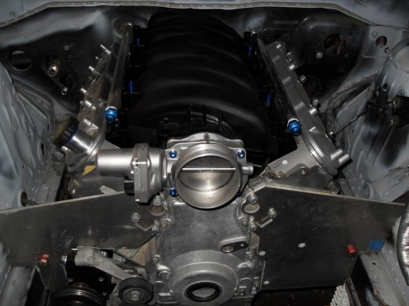
I also cut up some big ass PVC to check for header clearances.
What was I worried about?
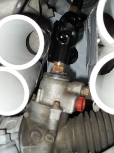
I can go 1 7/8" primaries and still have a full .25" clearance everywhere!
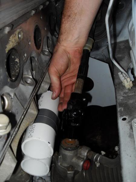
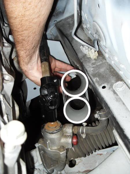
I under-estimated how much there is to this tuning thing with the AEM. The base map for the miata kinda sucks. I figured wire up the sensors, slap in the new tables, I understand AFR and timing, I'll be fine!? What about sensor lag time? Coil dwell time? Cam/crank sensor sync offsets and a million other little check boxes that can blow your shit up!? Plus the "instructions/help" merely define the basic pull down terms. No where does it tell you when to change them, why, or in what direction. I thought the link was bad with all of it's windows. There is Soooooo much that you can do with the AEM EMS this is going to be a steep learning curve. I better go buy some 110 octane.
Anyone in Long Island got EMS skills?
8/11/09
I talked to a tech at ATL today. I've been trying to figure out an economical way to roll with a fuel cell rather than trying to source a stock fuel tank. I watched the show “A Thousand Ways to Dieâ€Â a couple weeks ago, where they showed a real gruesome video and interviewed a Modified racer who survived a fiery crash that set his fuel cell ablaze. He was all scarred in the face. Makes you stop and think about what the hell you’re doing.
Fuel cells are required in very few classes, and are usually only installed at the builders preference. If you are not using a stock tank, the rules get heavy fast. Basically, NASA is spoiling all the cheap fun. They are no longer issuing log books for cars with non FIA, FT3 approved fuel cells (presuming you’re not using the stock tank).
The FIA has three main ratings with FT3, FT3.5, and FT5. Each has increasing tensile strength requirements for the bladder. The stronger bladders are recommended when higher speeds are expected. ATL managed to get a polypropalene (like the RCI, RJS, Jaz tanks) tank approved by the FIA for FT3. A lot of people seem to think that this is a great budget solution. But I think that many are overlooking that fact that in order for that tank (the ATL Saver Cell) to actually meet the letter of the law of FT3 it MUST be enclosed in a metal container; even though ATL will sell one without the metal container (they include directions on how to make your own).
Almost all of the bladders have a five year expiration date. And can be legally re-certified for an additional 2 years. The cost is $175, and ATL must receive the bladder before the end of the 5 years. There is a test strip that is within the bladder that they remove and retest for tensile strength. But, it seems that these rules are very poorly enforced by both NASA and the SCCA.
Ebay always seems to have tons of really cool looking cool looking check-ball valve lids. But it turns out that those shiney balls weigh 3 lbs each! Oh and in severe accidents the weight of the ball can mangle it’s pretty aluminum cage, and then they don’t seal! So Nascar is getting away from using them, and that’s why you can score them so easily. The tech at ATL said that they have come up with a new paddle valve that works much better, and he recommended p# TF703 $340.40 (Remote-Fill lid, Off-Set Paddle Valve) for my project. Though, the paddle valves can be had separately $76, and I might be better off to just retrofit one to an e-bay, surplus Nascar lid.
I cut out the floor of the trunk. The frame rails pinch in near the rear sub-frame, and at the front of where the trunk floor used to be it’s only ~35â€Â wide. The bottom of the trunk is ~19 front to rear. Because of this I like the dimensions of ATL’s 22 gallon (85L) “Câ€Â tank. For reference: the 1995 s14 tank holds 17.17 gal (65L). I would go smaller, just to get the tank further away from the rear corners (crash zones). But I’m still day dreaming of running alcohol someday, and the extra volume would be nice.
I already have a new in-tank Walbro 341 fuel pump, and have decided against an external surge tank. ATL makes an internal sump for $190 with 3 trap doors , that eliminates the need for a second fuel pump, a second tank , and another set of lines and fittings.
Below is a list of current costs of the 22 gallon cells I’ve been looking into. (smaller cells are slightly cheaper)
FUEL SAFE NEW
$284
SC122A SPORTSMAN STEEL CAN 34" x 18" x 9.5"
$424
ac122a-sb race safe al can 34" x 18" x 9.5"
$437
RS122A race safe hard plastic like enduro but with nice fill plate
$555
race safe cell with steel cont
$496
enduro core = assemble req. with top, no can
33.625" x 17.500" x 9.063"
$736
ED122A enduro complete 20Gauge steel (nascar's are 18)
$416
RB322A enduor replacement bladder
$1050
SM122A sportsman soft complete
$686
RB222A sportsman bladder
$1354
PC122A procell complete
$860
procell blader
ATL NEW
$382
aluminum can 15 lbs
$318
STEEL CAN 25 lbs 34.00 x 17.50 x 9.50
$1090
SUPER CELL, soft rubber and FT3+, no alcohol
$790
22g sports cell, 43lbs, hard plastic with steel can FT3+
$501
SAVER CELL, 22G SA122C 22LBS, 33.18 X 17.06 X 9.25
$732
super cell bladder
$452
saver bladder only
$1,100
BANTAM is kevlar and FT5+ bladder (only 3 lbs!)
EBAY
$515
18G NASCAR EXPIRES LATE 2011 - 33" X 17" X 8", no lid
$850
expiration 03/10, 3 DOOR SUMP, 22G, NASCAR, KEVLAR, remote lid
$650
expired, 3 door sump, 22 G nascar, remote lid included 33" wide x 9.25" tall x 17 deep
$500+
mustang 16g Aluminum (not FIA)
“I've been trying to figure out an economical way to roll with a fuel cell rather than trying to source a stock fuel tank.â€Â
…FAIL
8/18/09
I spent all day running down parts and installing a new fuel pressure regulator in the miata. I started to feel comfortable street tuning the upper rpm ranges of the miata and I was leaning out a tad (11.5 AFR). I kept trying to increase the fuel until I noticed my duty cycle was well over 100%. After a little research it also turns out that the stock miata FPR is only maintains a 1:1 boost reference to about 15 psi. And with my new pulley I've already seen 16.8 psi out of my whipple! That's a supercharger, and that's at the manifold, after the IC!!!
I had to use a SARD adapter and 90 degree fitting to get my VISHNU dual feed fuel rail to dump into a -6 line. The 90 fitting was $34 for -6. Really? Fuck SARD. Oh and the adapter had the holes drilled a full half inch too close together. I had to notch the shit out of it.
I'll be on my way back to Jersey to hit up my old shop TTP for dyno tuning and a little schooling on my AEM EMS by the owner/tuner Matt Sorian. Check 'em out they're always building something bitchin.
TT Performance Parts Inc - Where Shopping Is At The Speed You Want
I'll post the miata dyno sheet tomarrow, presuming I don't blow it up!
I've been trying to sign up for the Oct 9th Watkins Glen Last Chance Drivers School hosted by the NE SCCA. But none of the links are up for signing up. Is it normal for the sign ups to only be available near the events?
8/31/09
Dyno Session for the miata at TTP didn't work out. I got bumped by a paying costumer's problem child twin turbo mustang. It was cool watching Matt tune in another 200+ hp though. It was making well over 700hp by the time I left. While I was there though I installed a new walbro 255 to replace the 190hp. FYI a 190hp is NOT ok at 300 crank hp in a supercharged application. Now I'm debating even using a walbro at all for the LS7. Corky Bell told me to stay away from the walbro and go bosch or pierburg. I don't think you can score the bosch for less than 200, and I'm still hunting for a good place/price to get a pierburg.
I also just scored a nice used ATL fuel cell on ebay. Should be here in a week or two. It's p# SU122E which is a soft rubber bladder 22g tank 33"x17"x9". I'm thinking about using 1" square tubing to mount it. Anybody know anything about mounting fuel cells? Any circle track regulations that might be a good guidline etc? Can it be mounted leaning forward, or would it be much smatter to mount it flat with the pick ups in the back. I think it has a pick up in both back corners, right now, but I havn't ruled out putting a sump in the front middle.
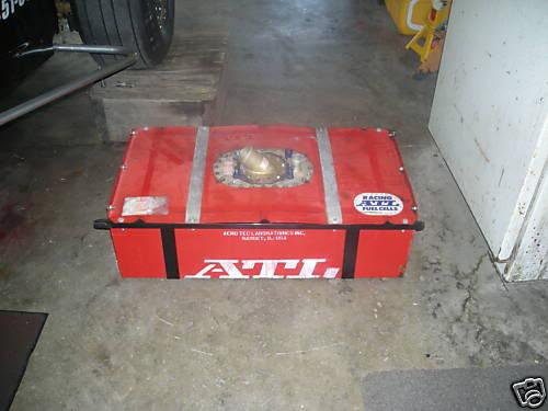
The Fuel cell has an expiration date of March 2013. I'm going to feel like a jack ass if this car isn't running by then.
10/7/09
I just got a refund from ebay for my fuel cell. And I had to get my credit card to refund me for a largus front sway bar after I tried to buy one from
streamlineparts.net
That never showed up either. I also ordered an air nibbler, to make an aluminum radiator shroud, from harbor frieght. It took them 5 days before they even processed my order and another 6 to show up. It sticks about every 12 inches, but it got the job done. Now I'm on the hunt for a rivnut tool to attach the fans and shroud them selves. If you don't know what a rivnut is you should google it, pretty cool.
http://www.youtube.com/watch?v=SN7w_...layer_embedded
A little nonsense: I think I'm going to need a license plate that reads "RB70SE"
10/23/09
Bunch of little stuff lately. I've been trying to do projects that don't cost any cash, but then my argon/CO2 tank went dry and I spent $40 bucks on bolts a bit more on cut off wheels and a nibbler. Later C note...
It's crazy how many hours these little projects suck up!
I'm using the same .75" willwood master as everybody else, but I lost the nissans original so I couldn't swap over the original clevis. I fabed up my own clevis by welding steel stap to two sides of a coupling nut. The clutch pedal has a very strange size hole for the original clevis, its close to 9mm or 11/32". I didn't want to just drill it out because it has a thin steel bearing type insert. So I turned my drill press into a make shift lathe and filed down a shaft bolt. Turned out great.
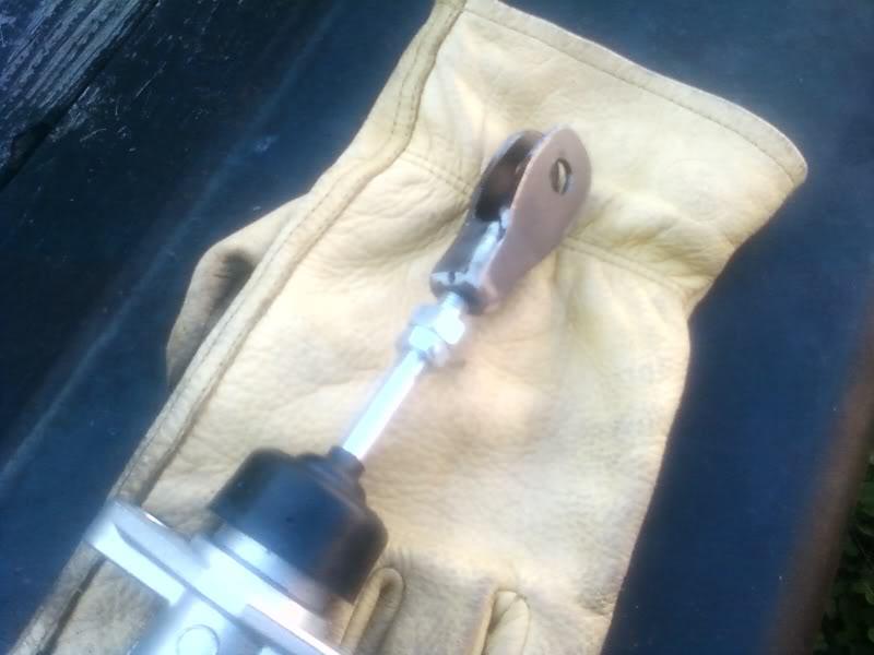
I don't think that these plates are really necessary, but I made one anyway.
On one of the silviav8 forums I saw that some guy manufactured a bunch of plates like this but with studs to make this a true bolt on affair. But the fire wall is doubled at the MC and the force is pushing towards the firewall so I don't think that the plate is necessary. It did make a nice template for drilling holes though. On the inside of the fire wall I welded square bolts for the willwood directly to the firewall, so that I don't need a second person to tighten the nuts/bolts from the engine compartment.
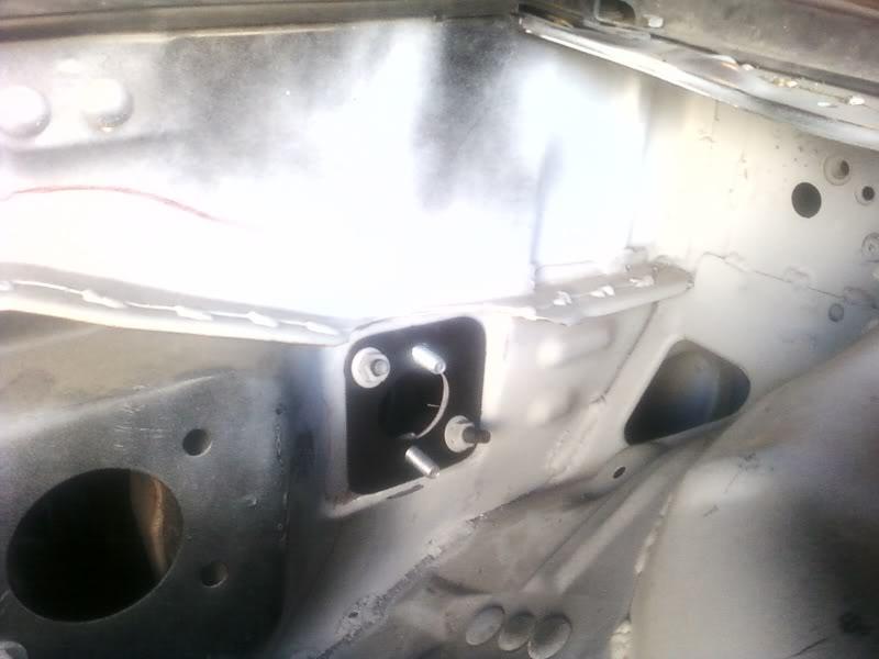
a little shroud work
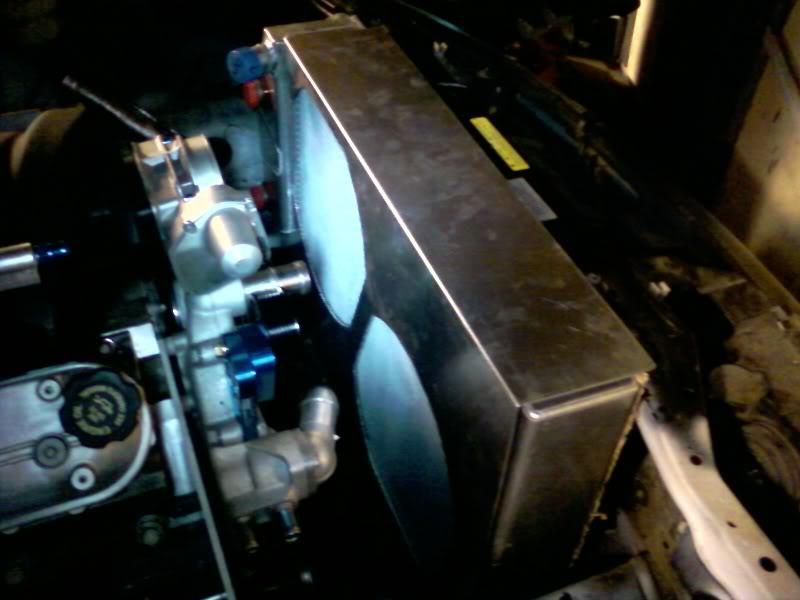
Stillllllll working on my crazy ramp/flat floor seat mount platforms
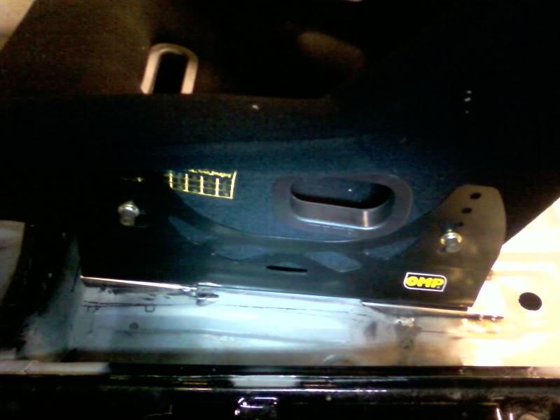
I've agonized over tearing out the sunroof since I bought the car. No going back now! I'm going to see if I can't talk my uncle in Florida into pulling a mold off this thing and making a couple out of carbon fiber. Mike at cognition made one for his time attack S14, but then the mold broke when he pulled the first piece
My Weights and Measures Division, NIST calibrated harbor frieght scale said 25lbs... At least! I'm glad it's gone, even if it is one more thing to do. 25 lbs feels heavier than it sounds if that makes any sense.
10/26/09
It looks like Kognition made another mold and is producing sunroof cover panels again.
http://zilvia.net/f/interior-exterio...0-shipped.html
Kognitions piece goes on top like a riveted on aluminum panel would. I really want the cover to sit flush with the roof though, this will probably require trimming down kognitions piece, then welding in a small shelf for it to sit on, plus a small amount of body filler to make it all smooth.
I'm just glad I don't have to make a mold now!
I also saw on kognitions web site that he weight the stock sunroof at 24 lbs. But claimed a 70 lbs weight reduction from a full carbon fiber roof skin replacement! I'd love to do a full CF roof, but that would knock me out of street class for sure.
1/17/09
I've been working on correcting the ergonomics since I've moved the seat so far back. Sparco makes the longest 6 hole steering wheel spacer that I could find, but its less than 3 inches. I needed the steering wheel moved back 4.75" to get it where I wanted it. I had access to a lathe, and with a bunch of help from my stepfather Tony, we made this:
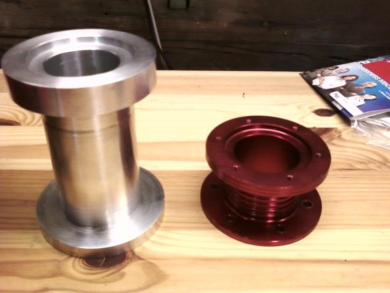
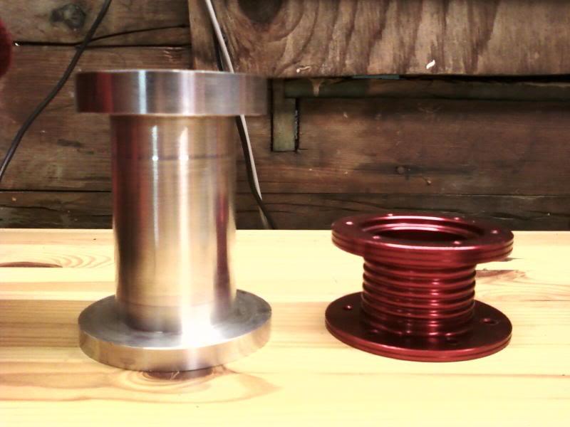
I doubled the thickness of the sparco flanges, and the main pipe wall is about 0.25". I still need to drill and tap a few holes, and make it pretty...
I also wanted to move the shifter location back 4.5", towards the driver 2.5", and up 1.5". Using some clever angles we were able to mill a simple piece of 1x2 billet. It took about 12 hours of machine time to make both pieces
3rd gear
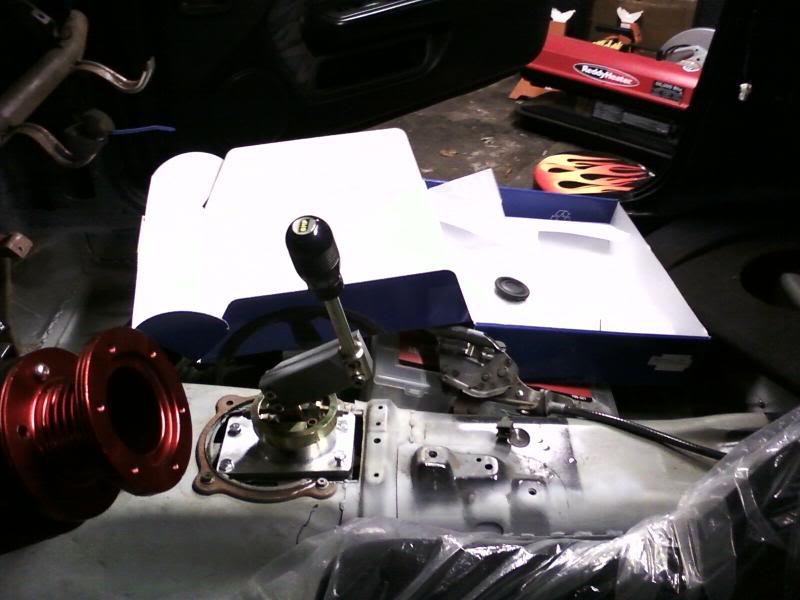
4th gear
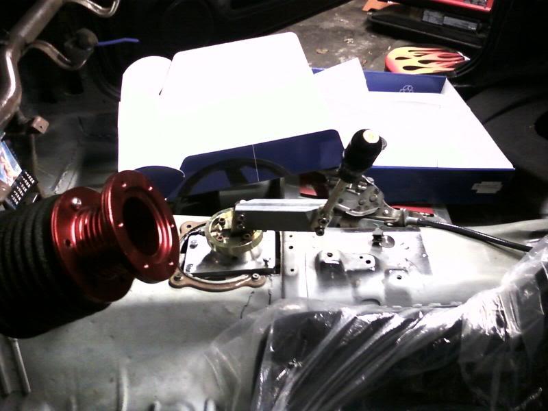
Next, the brake and clutch pedal need to get moved out about 3", and I need to make a mounting platform for the drive by wire pedal. Good times!
Now there is no room for the e-brake in the stock location. Does anybody know if the right-hand-drive silvia mounted the e-brake on the right side of the transmission tunnel, instead of the usdm left?
2/12/10
I finally got my harbor frieght metric tap kit in the mail so that I could finish my steering wheel spacer. I had to go to grainger to find a 4.2 mm drill bit for the 5mmx0.8 thread tap though. And after all the trouble the cheap ass tap made some crappy loose "like swishing your dick in the atlantic" loose threads. Sorry it's a translation from an old Japanese insult book that my friend and I used to bust up over. Who would have thought? Cheap taps make shitty threads? It works well enough though:
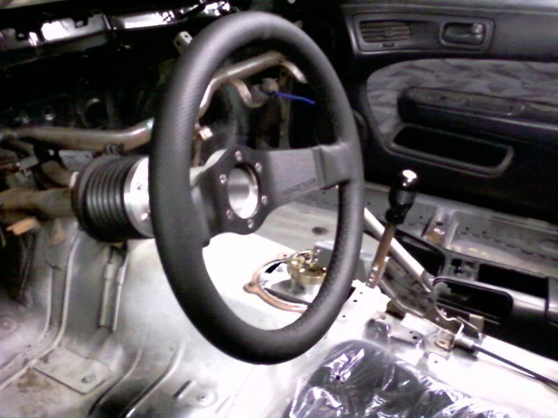
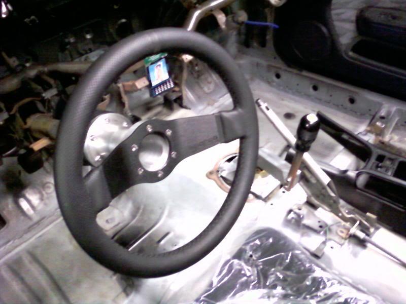
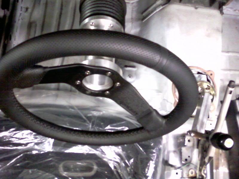
I also scored this for a freakin steal from a guy on LS1tech, good to 1000 hp. I later found a guy with a turbo LS1 in a malibu or chevell or somthing that was having problems with this pump and pressure changes. He switched to an Aeromotive,but with FPRs and turbos, I'm not going to jump to conclusions and hold anything against it. Besides this retails for more than $429 and the aeromotive is >$500! This is also 100% rebuildable to like new and is supposed to be very reliable for the street and increadibly quiet.
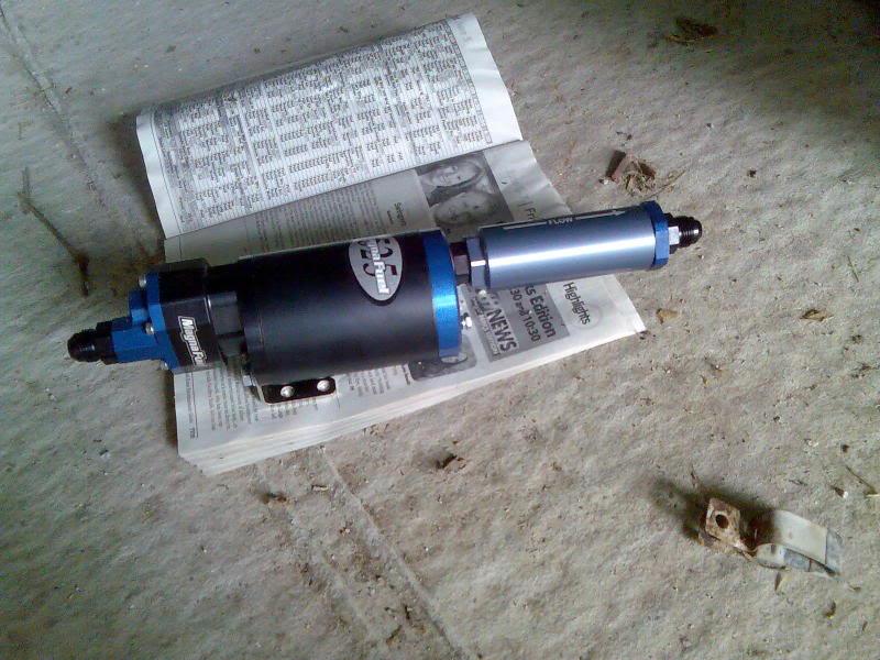
While I'm getting crazy with pics... I just can't figure out the best way to seal up the rear. This looks promising, but I want a REAL seal. No smoke, exhaust, spilled gas fumes, nuttn! You'd probably have to take out the glass for this one. Any other ideas? Post some pics!
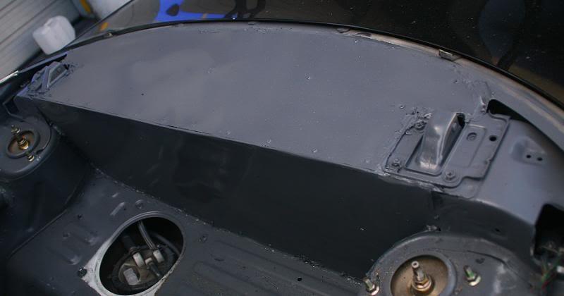
Thanx for following along!
2/17/10
I was originally going to reuse the stock powersteering reservoir, but I found this on ebay for $35 and figured it would be easier to hook up with its AN fittings, and that the extra volume and filter couldn't hurt. I think these were originally designed for off road race cars, I got it from a buggy shop.
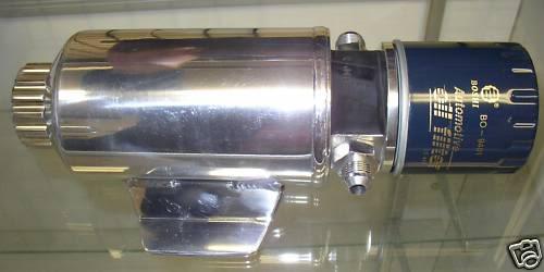
I also read a cool article about slowing down the LS1 powersteering pumps. It can help reduce overheating, overboosted feel, and can be worth 1-3 hp.
Turn One's Power-Steering Pump - GM High-Tech Performance Magazine
Turn One: Catalog: Power Steering Pump Directory: LS1 Pump
The pumps are blueprinted and I would use their universal pump which can be oriented in any direction and has -6 outlet, -10 inlet. With billet wheel it costs about $300. I called turn one and asked about their recommendation on using a PS cooler. I would prefer to not use one as it's just more places for leaks to occur. They said to plumb it up without one, and then to use an IR thermometer after a hard track run. As long as the temp is < 275 F you're golden, no cooler needed. If not...
I've been getting confused as to which fittings I have already, and which ones I need to order. I found this chart which I blew up and printed. I like to laminate cool/usefull shit (like the LS1 engine torque settings tables) and post 'em in my garage. Here's the cool AN ferrule indentification chart:
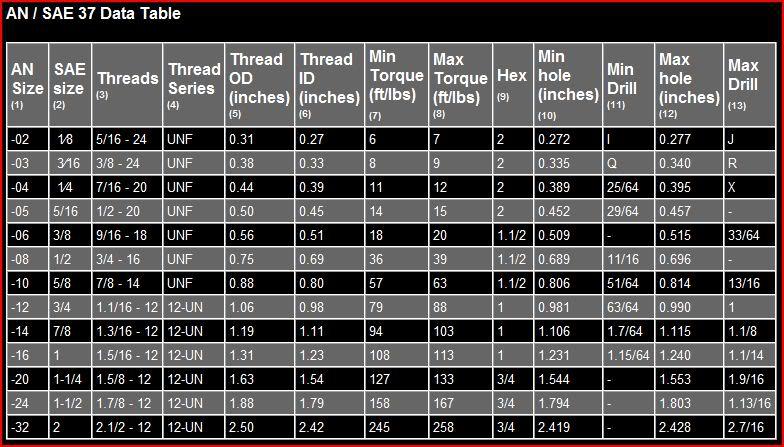
I found the following posted on the nissan road racing forum:
"Power Steering
Oil Pump Relief hydraulic pressure - 1,390 - 1,484 PSI
Fluid Capacity - Approx. 1 L
High Pressure
> PS Pump Banjo Fitting = 16mm Banjo
> High Pressure Steering Rack Fitting = M14x1.25 inverted flare
> PS pressure Sensor = M12x1.25
Low Pressure
> Low Pressure Hose OD = 3/8"
> Reservoir Host OD = 5/8"
> PS Pump Return fitting OD =1/2"
> Rack Return Fitting OD = M14x1.25 inverted flare"
Should help me to make the right hoses. If anyone can verify or correct the above it would be MOST appreciated!
2/17/10
I had a long conversation with the tech guys at C&R radiator yesterday about how to plumb my nascar style radiator. Here's a couple things I learned.
1) Originally I was worried about the top being the input of the radiator because I was afraid it would push the air into the system. But there is a -4 port at the top of the radiator. Ideally this would be -6 and on the top/opposite side of the input. This port basically has the same function as the steam vents on top of the LSx heads: to allow air/steam to exit to the top of the surge tank.
2) The bottom of the surge tank should be connected with a -10 (but -8 will work) to the lowest point of the radiator near the radiators outlet. This recirculation line is supposed to help prevent pump cavitation.
3) Don't completely fill the surge tank. The air above the water in the surge tank acts like an air spring against expansions in the coolant.
4) I don't know how legal this would be in most classes of racing, but circle track guys sometime run the the overflow hose to spay on the windshiled instead of in a bottle. That'll get your attention!
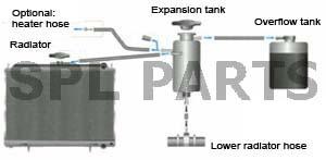
I also had some interesting conversations with Magnafuel and Lonie at Lonnies Performance Automotive ---- Main Index in Perryopolis, PA. I had heard of guys running pumps capable of more than 700 hp would re-circulate so much fuel at cruise that the fuel vaporlocks. Lonnie's solution is dual in-tank walbros triggered by a hobs swithch on boosted apps, and by both an rpm and full throttle switch. Magnafuel reccomended against fuel speed controllers, as their pumps weren't designed to run under 12.5 volts. They said that the one time they heard of their pumps vaprolocking it was fixed with a fuel cooler. I'm probably going to install a fuel cooler under the car.
2/20/10
What is the first thing that hits and stops/limits bump travel?
I started working on the rear subframe yesterday. I have the ebay solid subframe bushings. I measured the stock bushings and they sit somewhere between 12.6 and 13.6 mm above the subframe. SPL wasn't kidding when they said that you can raise your subframe half an inch! It's like a free drop spindle mod! But my cheapo ebay bushings have a 9mm lip above the subframe . So here are my options.
1. Buy SPL bushings and use their shims to get back the squat that raising the subframe gives up.
This cost more $, but still a very fair price.
2. Use only the bottom half of the ebay bushings
I worry that there would be too much stess on the bolts that hold the subframe with the top half of the bolt unsupported.
3. Machine off the lip of the ebay bushings.
This is complicated. If I machine the 9 mm lip off from the side, and drop the whole top bushings into the subframe-cylinder it will not fill the cylinder to the top. The cylinders in the subframe are 56.5 mm tall. Here's how that measures up to the ebay bushings.
The lip
from SCC:
"...Unlike the front of the car, small amounts of anti-squat are generally a good thing for a rear-drive car since it allows for softer rear suspensions without the excess squat.
Cars like the Nissan R32 Skyline GT-R, Z32 300ZX and S13 240SX have a great deal of anti-squat in their rear suspension geometry. This makes them transition to on-throttle oversteer very rapidly because anti-squat, like anti-dive, significantly increases the wheel rate. This is why the S13 works so well for drifting.
Extreme anti-squat can cause wheelspin and rear wheel hop under power, which is why the Z32 is notorious for launching poorly at the dragstrip.
Rear-wheel-drive drag racers have made a science of anti-squat tuning to maximize rear-wheel traction. Drag cars often have so much anti-squat geometry that the back of the car actually lifts when launching, driving the tires into the ground. Drag cars have adjustable four-link rear suspensions,so this percentage is tunable for the amount of bite desired in different conditions (see sidebar on page 102 to learn how to calculate anti-lift, anti-dive and anti-squat)."
Fun with fire
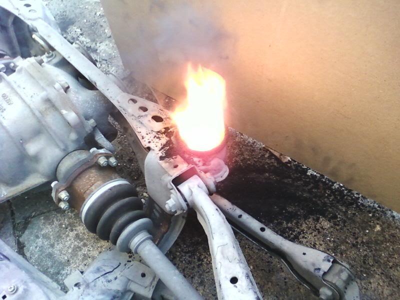
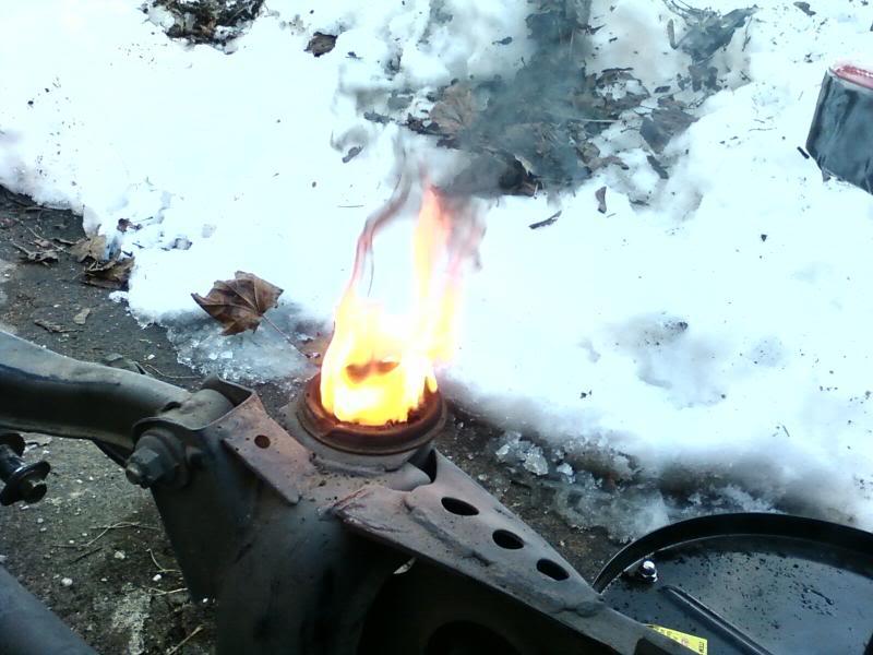
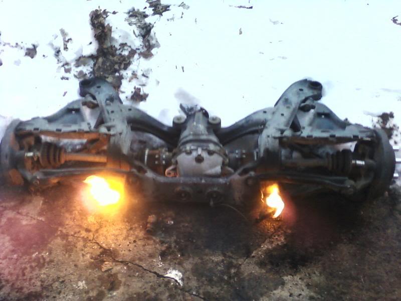
Tuning with anit-squat (here's my understanding):
More anti-squat: More predictable handling/transition to on-throttle oversteer. Allows softer springs.
Less anit-squat: More rear weight transfer, and better launch. Requires stiffer springs.
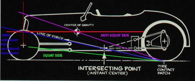
from SPL
for their subframe spacers:
For maximum squat (eg. drag racing), rotate the instant center down by installing large diameter spacers above front subframe bushings and small diameter spacers below rear subframe bushings.
For slightly increased squat, lower the instant center by installing spacers above all subframe bushings.
For slightly increased anti-squat, raise the instant center by installing spacers below all subframe bushings.
For maximum anti-squat (eg. drift), rotate the instant center up by installing small diameter spacers below front subframe bushing and large diameter spacers above rear subframe bushings.
for their solid bushings
Our CNC machined T6061 aluminum subframe bushings completely replace the stock bushings to eliminate free play of the subframe relative to the chassis, reducing wheel hop and improving suspension performance. Our new version 2 solid subframe bushings is designed to allow the subframe to sit up to 1/2" closer to the chassis (raising the subframe), which will allow up to 1/2" compensation of roll center for a lowered car.
However raising the subframe will not just change roll center, it will also increase anti-squat. Therefore our subframe bushings include 1/4" slide in shims so you can quickly raise or lower the subframe in minutes, and adjust the roll center and anti-squat behavior to best fit your driving style! Our unique adjustable subframe bushings offer a completely new way to tune the suspension behavior.
from www.formulaindyracing.com
Chassis engineers talk about "anti-squat" at the rear on acceleration and use a traditional diagram to calculate "percentage of anti-squat" (see illustration next page). Because the weight (center of gravity) of a typical road car is supported by the front and rear wheels, engineers draw a "100-percent anti-squat" force line from the rear tire contact patch to the front wheel vertical center-line, at the height of the center of gravity. If the actual "line of force" for the car – the line from the rear tire contact patch through the instant center of the rear suspension – coincides with the 100-percent anti-squat line, then theoretically the rear suspension will neither lift nor drop, and the rear of the car will not rise or squat, as the car accelerates. That is, if the instant center of the rear suspension lies anywhere on this line, the car will have 100-percent anti-squat. If the instant center is anywhere below the line, the rear will squat (or, have a certain percentage – a fraction – of anti-squat). If the instant center is above this line, it will have more than 100-percent anti-squat, which means the rear of the car will be pushed upwards by the suspension links as the car accelerates.
02/21/10
I updated the pic in the last post. Should make it a little easier to understand where you'd have to put SPL's spacers to get the effect you want.
I could never understand why the corvette had the alternator placed so high. I weighed my GTO alternator today, and it was 14 lbs!!! I have an F-body alternator bracket that will not fit a GTO alternator which has wider mounting boses. I plan on using only the botom mounting holes of the F-body bracket and lowering the alternator to almost the level of the bottom of the crossmember with heim joints and rod.
Red line will be the heim and hex
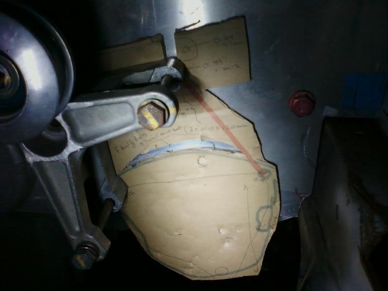
The corvette's alternator is actually above the head. That must be almost 2 feet higher, and 14 lbs!
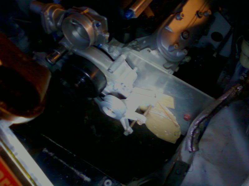
stock vette alt location

The old subframe bushings finally came in handy. I removed the metal cylinder from the center of the bushings and cut one in half so I could push the steel alternator bracket liner (marked with pencil) flush with the inside, so that the F-body bracket will be wide enough for the GTO alternator.
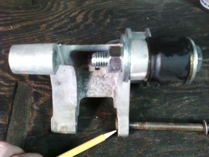
2/24/10
I called wegner motorsports about a 1/2" water pump spacer. They had two sets of 0.520" in stock at only $14 each!
[Recall I'm running a .25" motorplate and a corvette waterpump that is made to sit 0.75" behind the the camaro acc. offset I'm using. = 0.50" to make up @ the WP.]
I may have to knock them down a bit on the mill though. They told me that each WP gasket is about 0.060" thick. A normal application uses one, I'd have to use 3! Wegner suggested that I might be able to get away with just silicone and no gaskets. What do you guys think? It's all flat aluminum on aluminum. If I want to use all of the gaskets a perfect offset for the spacers ould be 4.880".
I've also started to label my wiring harness. It's a used harness I got off ebay a while back from a 2006 GTO. It was missing the interior harness and throttle pedal so I had speartech make me the extension harness for the GTO gas pedal I have. I'm struggling figuring out a few of the connectors. Does anyone know where I can get a wiring diagram with the wire colors for free?
I've figured most of it out just by looking at the connectors here:
EFI Connection
Thanx for the Christmas label maker Mom!
3/2/10
I purchased pipemax last year and have been very pleased with it. But I am having some trouble figuring out what lengths to use initially on a hybrid tri-y design.
Normally a try-y header is tuned to have the first collector at the very short 3rd reflected value usually about 15" from the ex. valve. It would be very tough to get the collectors that close and I'd rather use the further 2nd reflected value about 29" from the ex valve, this set up is sometimes called a hybrid try-y because the try-y collectors start where a traditional 4-1 would. Except for the LS7 header with the pic of the 67 camaro in the background the other pics are of honda headers cuz they are easier to see, and also one of the only communities where hybrid tri-ys are common.
traditional tri-y
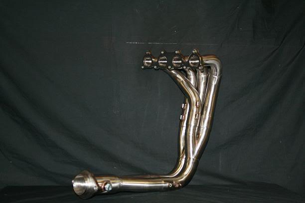
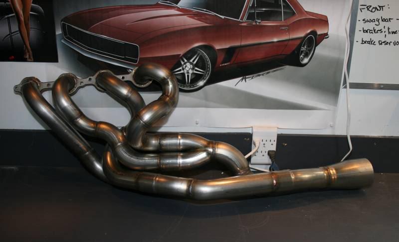
hybrid tri-y
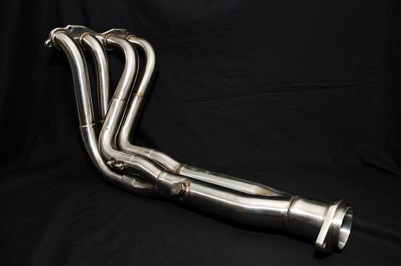
same collector location as a traditional 4 into 1
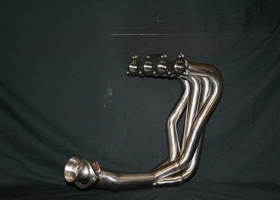
The following is a letter I sent to Larry Meaux, the creator of the program pipeMax: I have been considering using a pair of used nascar tri-Y collectors in place of a traditional 4-1 collector on my LS7 427 V8. Problem is I don't have room to use RV3 (14")as is traditionally done as the location of the first 2-1 near the heads. I wanted to place the first set of collectors at RV2 (28"). My question is, "can I use the 4-1 (3.5") header collector LENGTH quote from pipeMax for the pair of collectors (2.5" each) from the first tri-y step to the second, or does the difference in diameter change the length required too much? Suggested collector lengths are 16" 26" or 64", would I be better off using one of these lengths or RV3 (14") length for a third time. And what about the final collector length?
Just cuz I dig pictures: LS1 on L, LS7 on R
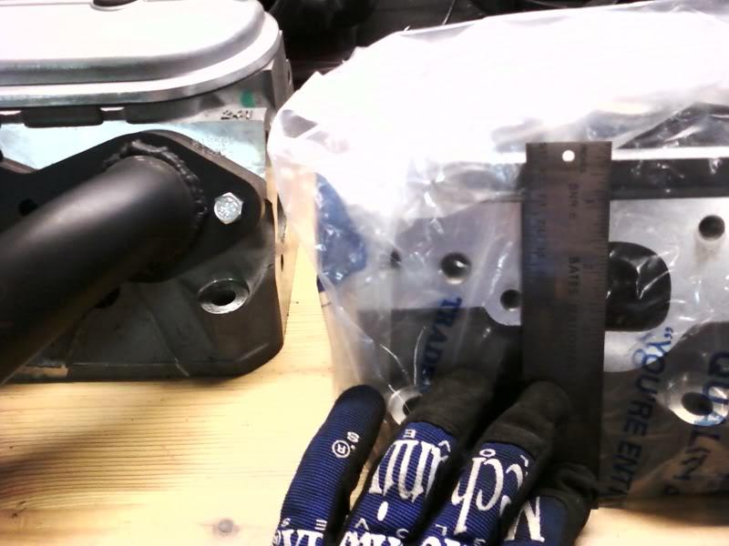
I was re-double checking that the LS7 and LS1 had the same location for the header bolts. They do.
I also got the a response from Larry Meaux, the creator of the PipeMax program. That was really cool of him, he didn't owe me nutt'n but sent me this great response.
"One thing-> when you switch over to TRI-Y design,the Primary 1st and 2nd Segment Lengths are very important
they must be within an inch or two from PipeMaxbut you can also "double" their lengths if necessaryto fit Headers inside bays or for a little more Torque.
TRI-Y example->suppose PipeMax predicts the total length of the 1st & 2nd Segments = 25 inchesthen you could use 50 inches if you needed to , but nothing in between
but if it was a 4-1 Header,then you could have very different Primary Pipe lengths (Unequal length Headers ),and not really see too much Loss if the Collector dia + its length were perfect to what PipeMax predicted
so in other words,
TRI-Y = Primary Lengths are almost as important as Collector Lengths 4-1 System= Primary Lengths are not that important, but Collector Lengths are critical !"
3/5/10
Larry Meaux from PipeMax is going to get back with me today with a picture of how I should build my headers! And last night I used some scrap steel and a dimple die to make the adapter for my throttle pedal. When I drove Courtney's LS2/S14 I saw that he had a simple 0.25" thick aluminum plate that bolted to the car's original bracket and shared one bolt with the GTO throttle pedal. Because I'm not as tall as he is, and my front seat is almost in the back seat I need the pedal ~2.6" spaced out. The brake and clutch peda will need to be spaced out about 3". Having the brake pedal sit about .50" closer to the driver than the throttle pedal will make heel-toe a bit easier I think? I ran out of argon/CO2 before I could finish. But here's where I'm at. It's very light and stiff already, and it's not even gusseted yet.
making it
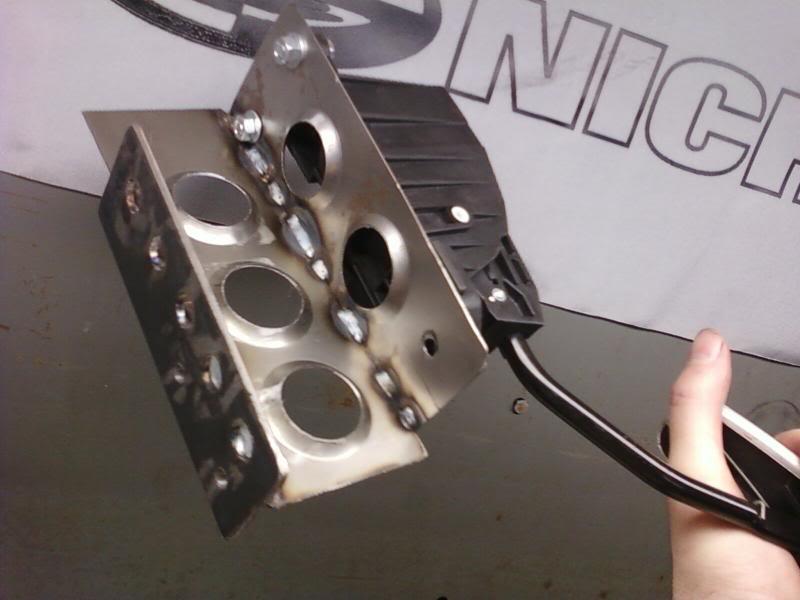
test fit
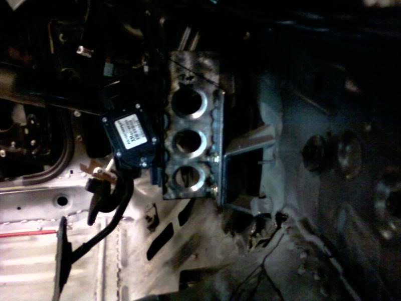
progress, it was hard to get even these tacks done with no shielding gas on such thin gauge steel
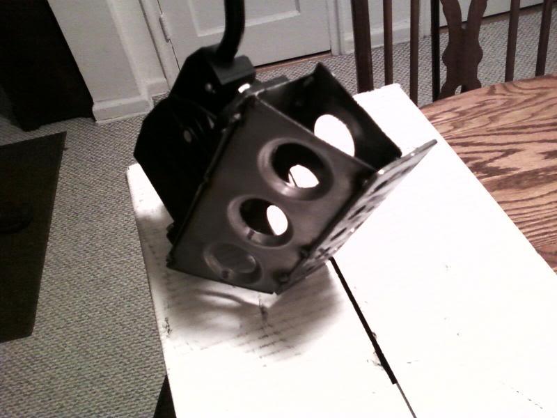
3/9/10
I got a set of new LS7 cnc's heads for <$1000. And in sticking to my budget had to forgo the ti intake valves which run about $800 a setand get stainless which are about 20% heavier.
For reference:
2.205 118.4g (the LS7 intake in SS from REV)
2.180 114.6g (a L92 valve in SS we use from REV)
2.160 106.5g (stock L92 replacement SS from REV)
1.600 92.3g (for reference an SS exhaust valve)
Stock LS7 Ti intake valves are probably in the 95g range as a guess.
Richard at West Coast Cylinder Heads hooked me up with the most serious valve springs that can still be used with hydraulic rollers, as I plan on using the GMPP Cadillac lifters. It's common knowlege that a lift much over 25% of the valves diameter usually yields very little gain in flow. The LS7 head is no exception.
As you can see from the flow data below. The flow at 25% of the 2.205" intake valve diameter (at a lift of ~.550"), to its max flow which is at .650" lift, the flow only increases 4.4% with the manifold on. And with the manifold off the flow actually decreases at lifts much greater than the magical 25% diameter lift height!
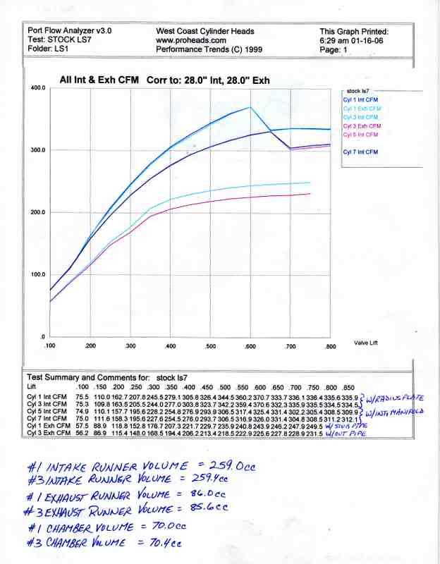
Here's a chart I made regarding piston velocity: @ the LS7s stock 4.000â€Â stroke which I plan on using.
RPM FPM
6000 4000 safe (street)
6300 4200
6500 4333 max (street)
6750 4500
7000 4666 LS7 sits here stock
7200 4800
7500 5000 GENERALLY CONSIDERED SAFE IF ALL FORGED COMPONENTS.
7650 5100 R07 nascar engine
8000 5333
8200 5466 Tosto Drag LSx
"During GM's reliability testing of this engine in its prototype phase, the LS7 was remarked to have been repeated tested to be 8000 rpm capable, although power was not made at that rpm level, due to the restraints of the camshaft's profile and the intake manifold ability to flow required air at that engine speed."
I see no reason a forged LS motor with a 4" stroke shouldn't have a 7500 rpm rev limit. 5000 fpm is considered a safe limit with many engine builders if the bottom end is built entirely of all forged components.
Unlike GM I can use whatever cam I want, so my limiting factor has become my valvetrain. I'm hoping to get around this with some seriously honkin valvesprings and stout push rods. Here are the springs I currently have.
My springs:The valves are REV stainless steel valves part numbers X1131 for the intakes and X1137 for the exhaust. And use 10 deg locks.
seat diameter: 1.450" (My LS7 heads were machined to take BBC size springs)
installed height: 1.855"
seat pressure: 163 lbs
.600" lift: 404 lbs
.650" lift: 426 lbs
.660" lift: 430 lbs (max rec lift)
I havn't measured coil bind yet.
Now the limiting factor is the 1.8:1 LS7 rockers give some lobes too damn much lift. And the other limiting factor is that I fear some of the more popular cam profiles might be too aggressive for such a heavy valve at 7500 rpm.
For example a comp cams LSK 240 duration at .050" lift lobe would have a lift of 0.687" lift with the 1.8:1 rockers! Too much for even my crazy BBC springs! If you want to figure out the lift that a lobe has that's quoted fot 1.7:1 rockers just multiply by 1.0588 to get the new lift with 1.8:1 rockers.
Common LS based comp lobes at 240 duration at .050" lift.
XFI (at 242) 0.648"
XER (at 240) 0.645"
LSK (at 240) 0.687"
Richard at WCCH suggested that I not go too much over 0.630" lift. Looking at the flow data of the heads with the manifold on I can see why. I'd like to keep using stock style lifters to help with the budget. So now the question is which lobe is going to help me get there?
I need something gentle, but of course don't want to sacrifice any ramp speed that I don't have to.
I know there's not a whole bunch of cam engineers following this thread, but I'll keep u guys updated as to what happens and maybe we can all learn something.
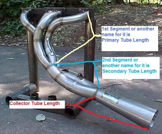
I had been wondering whether or not the primaries ended at the start or end of the first collector.
Larry Meaux of the pipeMax software fame sent me the above photo.
And the following info:
I also have a set of tri-y collectors from nascar surplus that are for 2 OD primaries, and have 2.25 OD secondaries leading to a final merge collector that expands back out to 3.5. I also have a bunch of slip on extensions so that I can get what ever lengths I need, and to make dyno tuning a bit easier if I ever get to it. I'm hoping to use them if they aren't too far off.
__________________________________________________ _______________
What you already have above sounds perfect !!!!
i calculate TRI-Y specs at :
anywhere from :
1st Primary Segment= 1 7/8ths to 2.000" diameter x 13.1" to 14.5" inches long
2nd Segment= 2.000" to 2 1/16ths diameter x 13.1" to 14.5" long
Collector tapers or diverges from 2.811" to 3.816 over 16.0" inches long
so the 2.811 could round-off to 3.000 if need be
and the 3.816 could round-off to 4.000 if need be ?
a merge collector ending at 3.5" diameter looks OK too , its in the ballpark.
___________________________________________
for TRI-Y's, the 1st and segment lengths are critic also they could either be->
13.1 to 14.5" inches long for each of the 1st and 2nd segments which = 26.2 to 29 total length
or they could be 26.2 to 29 long for each of the segments which equals = 52.4 to 58 total lengths
the 13.1 to 14.5 will give you the most HP
the 26.2 to 29 will give you the most peak TQ and bottom end
the only bad thing about TRI-Y's is that to see any real benefitsover a 4-1 Header, the TRI-Y specs must be exact ! otherwise you are better off with 4-1 setup
Larry MeauxMeaux Racing Heads MaxRace Software
http://www.maxracesoftware.com/
3/16/10
I had been wondering whether or not the primaries ended at the start or end of the first collector.
Larry Meaux of the pipeMax software fame sent me the above photo.
And the following info:
I also have a set of tri-y collectors from nascar surplus that are for 2 OD primaries, and have 2.25 OD secondaries leading to a final merge collector that expands back out to 3.5. I also have a bunch of slip on extensions so that I can get what ever lengths I need, and to make dyno tuning a bit easier if I ever get to it. I'm hoping to use them if they aren't too far off.
__________________________________________________ _______________
What you already have above sounds perfect !!!!
i calculate TRI-Y specs at :
anywhere from :
1st Primary Segment= 1 7/8ths to 2.000" diameter x 13.1" to 14.5" inches long
2nd Segment= 2.000" to 2 1/16ths diameter x 13.1" to 14.5" long
Collector tapers or diverges from 2.811" to 3.816 over 16.0" inches long
so the 2.811 could round-off to 3.000 if need be
and the 3.816 could round-off to 4.000 if need be ?
a merge collector ending at 3.5" diameter looks OK too , its in the ballpark.
___________________________________________
for TRI-Y's, the 1st and segment lengths are critic also they could either be->
13.1 to 14.5" inches long for each of the 1st and 2nd segments which = 26.2 to 29 total length
or they could be 26.2 to 29 long for each of the segments which equals = 52.4 to 58 total lengths
the 13.1 to 14.5 will give you the most HP
the 26.2 to 29 will give you the most peak TQ and bottom end
the only bad thing about TRI-Y's is that to see any real benefitsover a 4-1 Header, the TRI-Y specs must be exact ! otherwise you are better off with 4-1 setup
Larry MeauxMeaux Racing Heads MaxRace Software
http://www.maxracesoftware.com/
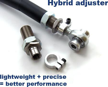
I'm trying to make my own RUCAs but I can't find any male/female double threaded tubing anywhere. Any body have any idea where they can be got? Locking ones like the above SPL would just be gravy. A guy on the nissan road race forums is hooking me up with spacers so that I can use 5/8" heim joints for the 12mm stock RUCA(rear upper control arm) subframe location bolt. So what would be best is a 5/8"-18 inner thread with what ever thread on the outside of the same tube.
These are interesting
Turnbuckle, Female, Steel Race -- Midwest Control Products Corp.
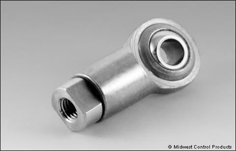
I was all excited when I found these. But then I saw that you can only get them with the same thread direction on the inside and outside. Am I conceptualizing this correctly: you adjust the nut... and nothing happens. The heim would move OUT of the "Thead Bung Adjuster" the same amount that the "Thead Bung Adjuster" would then move INTO the control arm?
Thread Bung Adjuster -- Midwest Control Products Corp.
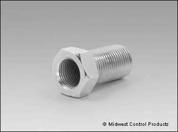
3/19/10
I guess there's no reason I couldn't use the ladder bar adjusters, or even a turnbuckle/female rod-end combo.
Here's the latest pic I made as a build guide for myself. I printed it out and hung it in the garage for reference. I doubt you're going to find 49"-55" headers (not including the collectors) over on LS1tech.com! Then again we are talking about the latest version of the SBC. It's hard to be the first to do anything on a small block. That try-y I posted a pic of above was built for an LS7 and dyno tuned at Katech. Supposedly it made the most average power from a header they had ever seen there. Coming from Katech who developed the C6R program... that's saying something.
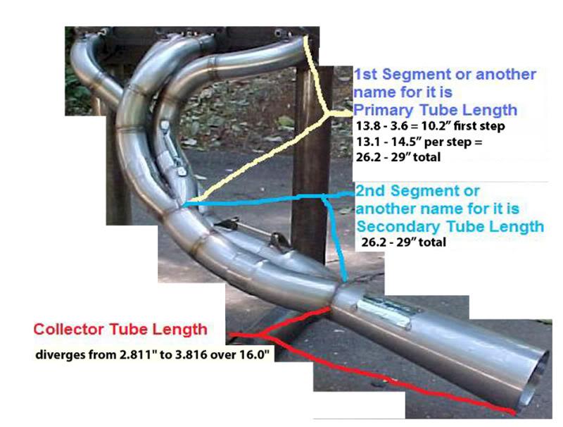
There will be a seal going from the bottom of the radiator towards the motor plates on the bottom, and a hood vent directly above/behind the radiator. There is also at least 9 inches from the back of the radiator to the motor plate. Given the space, crazy 3000+ CFM fans, and vent location I don't think there will be any cooling problems. It's true that not as much air will circulate around the engine, but with a flat bottom that was never going to happen anyway.
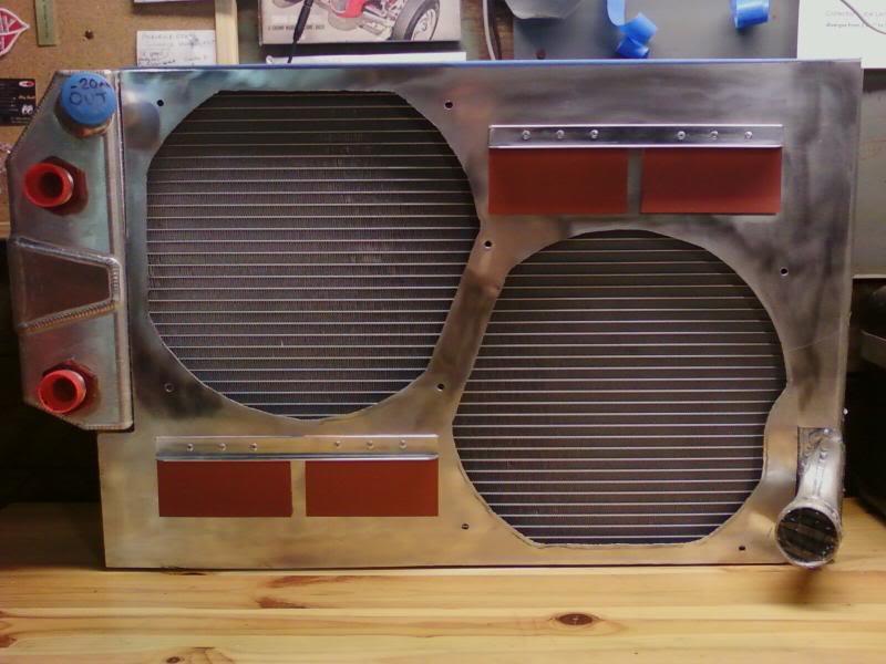
This is the first time I got to use both a rivet gun, and my polishing wheel. Good fun. These flaps were a semi-original idea of mine. I used a small piece of angle aluminum to sandwich flaps that I cut out of rubber that was originally meant for plumbers to make custom gaskets. The angle aluminum stiffens up the whole shroud, while the rubber acts as a slight vibration damper.
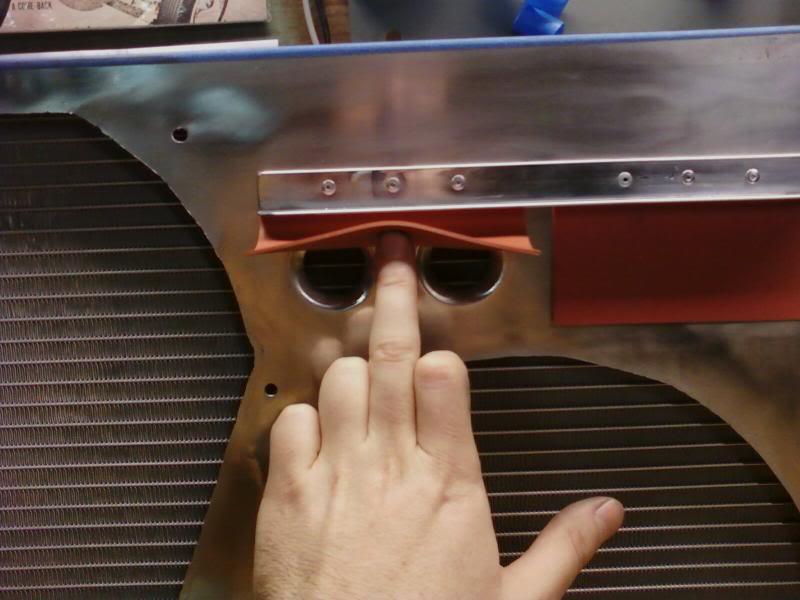
6/18/10
A recent Engine Masters Challenge redefined what blocks you could use the LS7 heads on. Just like the guys at RED I scored a bare set of LS7 heads for a screamin deal. But now don't want to pony up the cash for the big bore block that they really require. Before this article came out the smallest bore I've heard an LS7 head being on was a .035" over LS3 block at 4.100".
Here's the article in question,
Racing Engine Design 370 Gen III Chevrolet LS Engine - LS1 Performance - Popular Hot Rodding Magazine
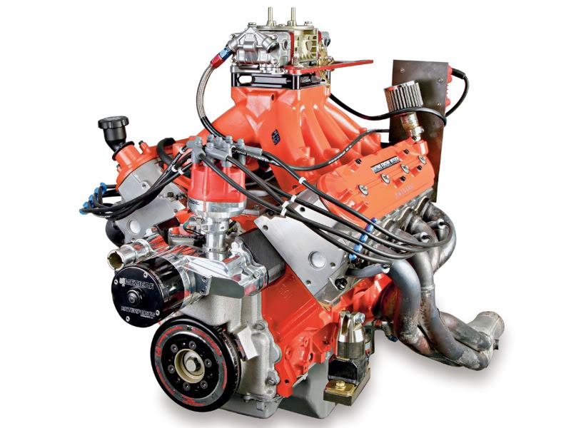
Per the article RED made no changes to the combustion chamber. But did swap out the stock 1.61" exhaust valves for smaller 1.54" exhaust valves. This would free up 0.035" on the exhaust side and possibly allow for a 4.065" bore, but the RED 370 supposedly was on a 30 over LQ9 block at 4.030".
Where did they come up with that other 0.035" of clearance? Moving the valves with a fancy valve job, offset block to head dowels? Or maybe it just works!
RED 370 EMC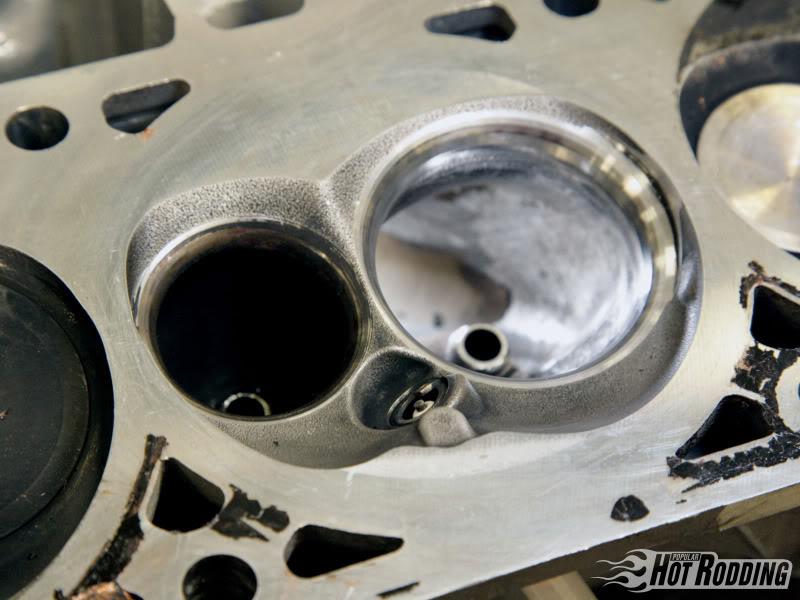
MY STOCK LS7 CHAMBERS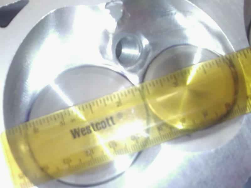
It doesn't look they moved the valve at all. And you can pick up an LQ9 block for $250.
10/14/10
Powers back on in the garage! I wanted to get the pedals all mounted up. The bolt-on throttle pedal mount I made was sturdy as all hell, but the stock pedestal was flexing so I made some reinforcements.
b4
after
So it's still a bit flexy... But it's the firewall that's flexing now, not the mount! I'm sure that my access holes aren't helping. I plan on replacing my hacked access holes with neat, clean, strong tubes with caps. That's still not going to stop the firewall from flexing though.
I've long wanted to make my own strut tower bar. And I got really inspired when I went to the (NAHBS) National Hand Built Bike Show in Virginia last winter.
North American Handmade Bicycle Show | NAHBS
A whole bunch of down to earth, talented, cool people. It was great. I would probably just buy something if I could find what I was looking for. Most 240sx strut bars are bent to clear the tall KA, and also never triangulate the firewall. Both glaring design flaws imop.
I love the bar that Matt Powers is rocking on his s14, but I suspect it was custom made. If anybody knows otherwise, or has better pics of his please let me know.
MP
MP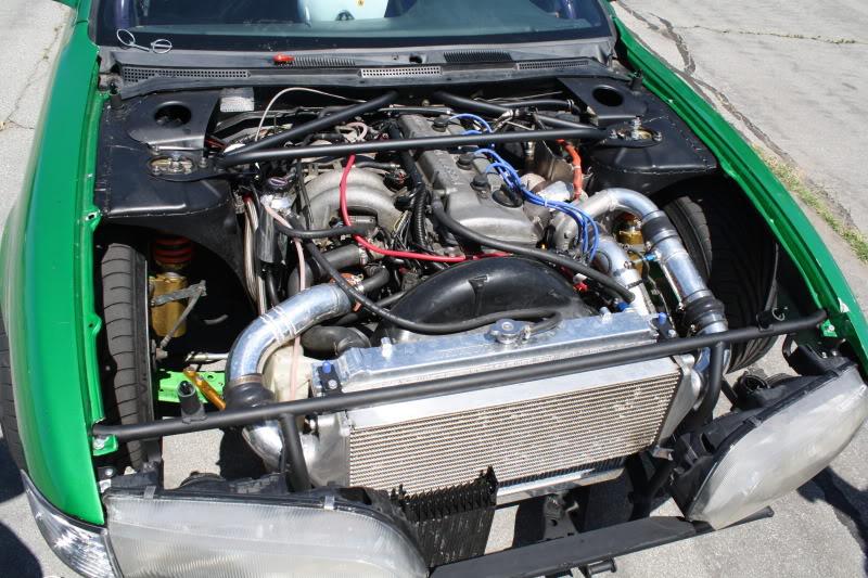
At the NAHBS I met a few guys that cast their own lugs (the part that connects the tubes of brazed (not welded) bikes. The custom artistry that many people carve into these is amazing. And as cast they are only $20 a piece.
I also spied the S&S stainless coupler for the first time. A lot of high end tandem bikes are starting to incorporate these to increase portability.
Features of bikes with S and S Couplers:
Strong: Couplings are stronger than the actual frame tube! No added flex!
Lightweight: Adds only 8 oz. (226g) to a road bicycle. (1"x1 1/8" tube size)
Durable: Rider reports 25,000 + miles with absolutely no detectable wear.
S & S Couplers
So if I can't find more info on Matt's strut tower bar, I might make my own using lugged chromoly tubing.
10/18/10
I started a thread on subframe reinforcement.
S14 Subframe Reinforcement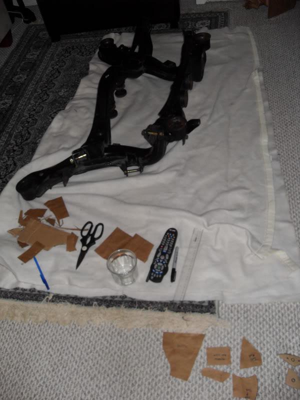
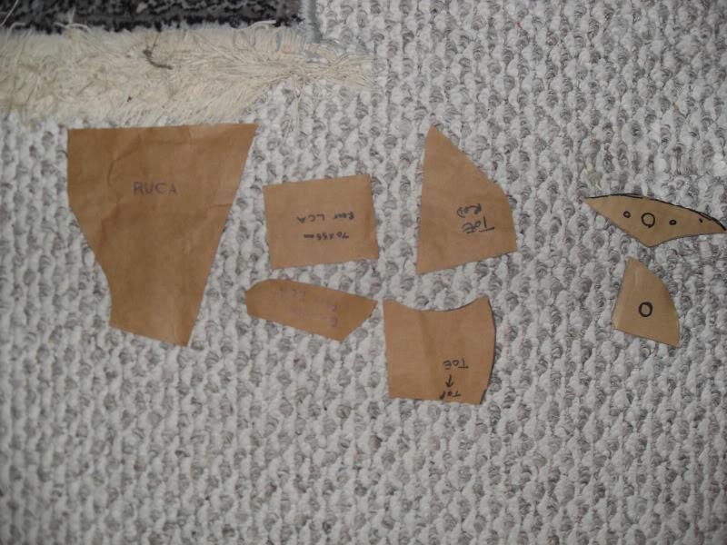
I've also been thinking about a Q45 diff swap (but keeping the 4.083 ring and pinion) just to get the supposedly beefier axles and VLSD until I can sace up enough for the OSgiken. I've heard that the Q45 has 30 spline axles, compared to the 29 spline s14 axles. Does anybody know how much thicker they are? I measured my s14 axles at 28mm.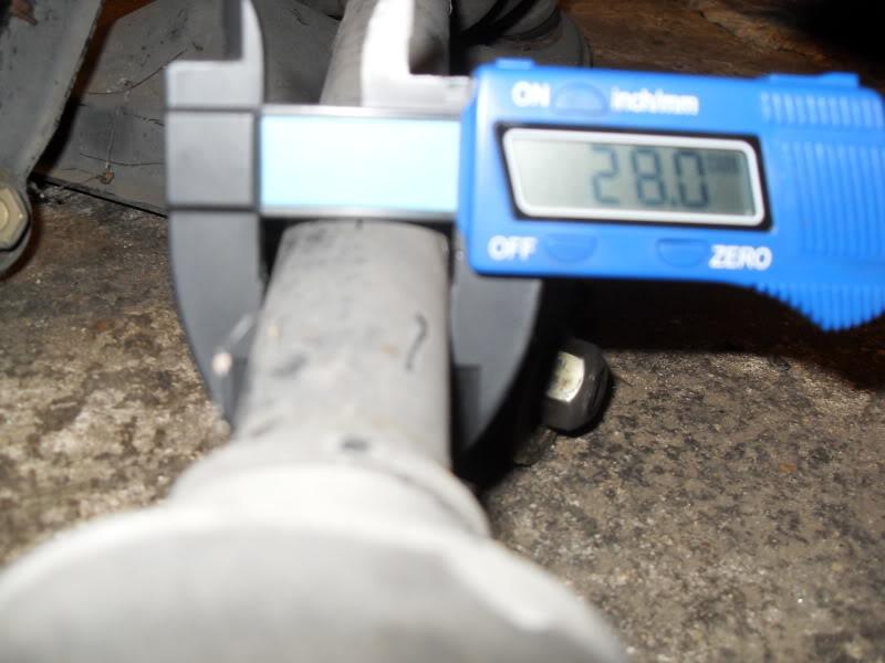
11/3/10
I've been working a bit on the rear subframe and thinking about squat. I've never seen anyone attempt to calculate what percentage of squat the rear had in it so I thought I'd give it a go. It looks like the S14 has about 200% antisquat!!! I misunderstood anti-squat before, as it's a little counter-intuitive. Drag cars like to have 200% antisquat, but the problem is, that can cause wheel hop on braking. So road race cars tend to have 120% to 150% anti-squat.
The pink line on the 240 represents 100% antisquat which = no effective induced force.
The blue line is where the line of force goes through the 240s instant center.
The two green lines represent 120% and 150% antisquat and conventionally if we could get the instant center to fall with-in range then you could seriously increase the rear brake bias, and thereby shorten stopping distances. 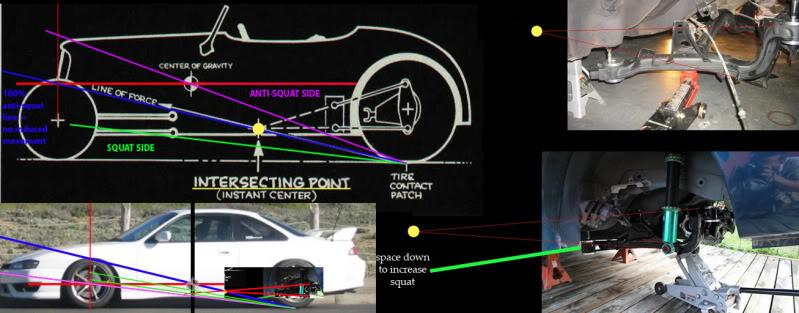
I don't believe that simple shims above the front subframe mount will be enough to get the anti-squat into a more road race like geometry. It's going to take lowering the front LCA mount, or raising the RUCA/subframe mounting location. If my drawing is at all accurate the S14 came from the factory set up like a drag car. And the S13 is set up to make no sense for anything.
11/18/10
So from all of my research the ideal antisquat for a roadrace car is 120-150%. Any more and you compromise braking performance, and on throttle oversteer. Any less and you're giving up some holeshot/corner exit traction.
Made some more of my own drawings and photographs. With my modified subframe bushings the rear is 0.160" from the frame, and the front is flush. I think I'm probaby going to grind the front down a bit. I can probably get the front another 0.100" up.
My S14
Ride height: 3.5"
CG height: 11" (presuming it's at the height of my crank center line)
Antisquat%: 56.40%
Most S13
Antisquat%: 151%
So basically the S14 has too little, and the s13 too much antisquat. I'l probably be relocating the traction or RUCA a bit.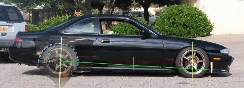
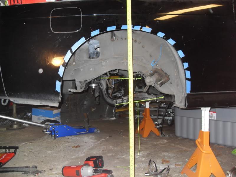
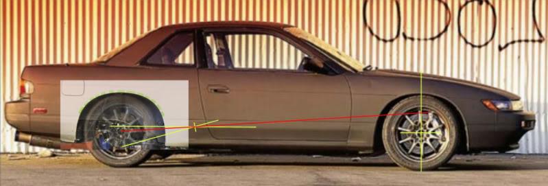
Also continued on reinforcing the rear subframe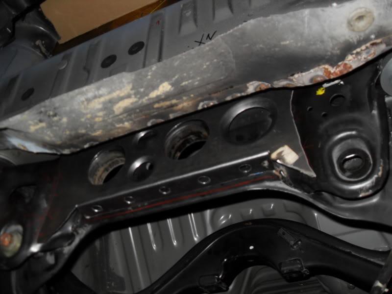
I was also a bit concerned about making my water pump outlet hose cross between the pulley and radiator fans... GM to the rescue!!! Found this add on ebay, ""LS3 WATER PUMP NEW Take off Corvette Cadillac STS" The offset is exatly the same as my old LS2/LS7 waterpump, but the outlet is on the driver side instead of the passenger side! Sweet.
Old Ls2 pump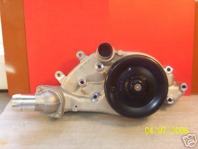
New LS3 pump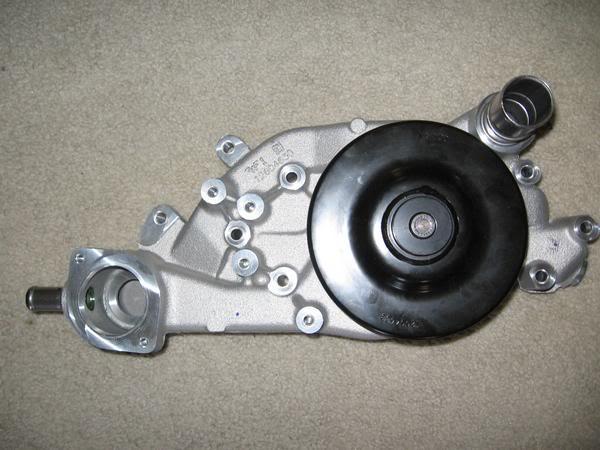
1/13/11
I've been paranoid that something was going to happen to my radiator unless I got it mounted since I bought it. And I'm finally getting close to having it mounted. The stock LS waterneck that is on the WP inlet side (unlike on a gen I SBC) sticks out at about a 45 degree angle and was preventing me from getting the radiator as far back as I wanted. It was also much smaller in diameter than my 2" radiator outlet. I picked up a 2" 90 degree cast aluminum elbow on ebay for like $5. I cut off the offending part of the original water neck, ported it out quite a bit and LM24 in Deer Park, Long Island welded the two up for me. Boom! An extra inch or so of radiator clearance, and I can move my monster heavy Nascar radiator further back to improve weight distribution.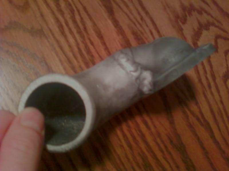
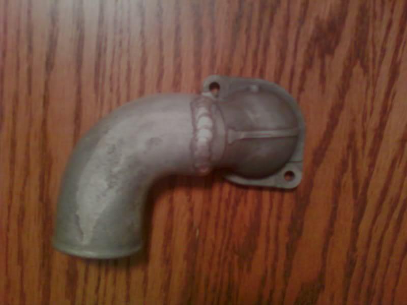
I also used a steering wheel puller to pull out the original stainless water pump outlet in the 2010 camaro waterpump and pressed in my -20 AN fitting that I also found on ebay.
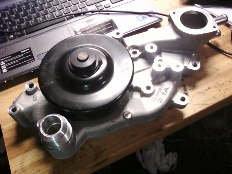
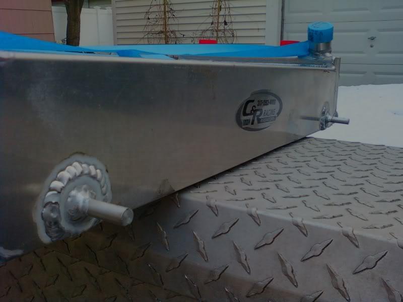
1/16/11
My uncle Greg and I were discussing building cars to race at Bonneville. We both had been drinking I think, but I think the conversation turned towards he putting up the pink on a 78 GMC motorhome against my 240sx's pink if/when we ever make it to the salt.
I did a little research as to what the minimum horsepower to achieve 200 mph at Bonneville would be for both a Motorhome and the 240sx. And plugged all the numbers into a calculator on this sweet web site.
RSR Aero-horsepower Calculator
BELOW IS THE WORST CASE FOR THE 240. I can definitely get it slipperier than the stock .33 Cd, and smaller than the stock frontal area of 17.88 sq ft. But per the calculator I'll need at least 428 hp to hit 200 at the stock size and Cd. The fastest guy on the 240sx forums claims he did 167 mph with 500 rpm left to go before he chickened out. He did it with a nissan sr20det at 1 bar of boost (he should be right at or below 395 whp) in his 240sx.
We can't be pullin upto the Salt flats in a POS, slow motorhome. Uncle Greg informed me that the 1978 GMC was the most aerodynamic motorhome ever made, and I'm sure he could improve upon it's stock Cd and frontal area a ton.
Now the motorhome: All per wikipedia:
All GMC motorhomes (produced 1973 through 1978) are 96 inches (8FT) wide and about 9 feet (2.7 m) tall including the usually-installed roof air conditioner. Interior head room is 76 inches (190 cm).Gross vehicle weight rating for the 23-foot (7.0 m) coach was 11,500 pounds (5,200 kg) and 12,500 pounds (5,700 kg) for the 26-foot (7.9 m).vMotorhomes tested via a wind tunnel were reported to have a drag coefficient of 0.31, which is typical of modern sedans (although offset by the large frontal area).
Pretty sad that a motorhome has a better Cd than the 240sx (.31<.33) !!! But that frontal area gets ya.
This is me being extra nice to the GMC motohome. At 500 lbs lighter than stock and 2 foot shorter. It requires 1230 hp to hit 200 MPH per the calculator.
Not as bad as I thought it'd be! 1300 horse power shouldn't be too hard. Especially if we leave the stock (then turbo'd) 455 powering the front (The GMC was FWD!!!), and put a turbo viper motor layin it down out back. Easy.
2/2/11
Holly crap! Have you guys seen this stuff? HTS-2000
Aluminum Welding - Aluminum Repair - Aluminum Brazing - AluminumRepair.com
YouTube - HTS-2000 Aluminium Repair For The New Millenium
I want it.
2/4/11
The good news is the car is closer to completion, the bad news is that I'm down grading to a stroked L76 (404 ci) to make it happen, and am selling the LS7 heads. This should knock me down from about 670 hp to 600 hp. Not the end of the world. There's always forced induction if I need more power. But since I want to race in street tire classes, I probably won't need any more hp.
Out:
LS7 Corvette Z06 Heads with REV valves and dual springs - eBay (item 130482421966 end time Feb-12-11 18:58:58 PST)
In: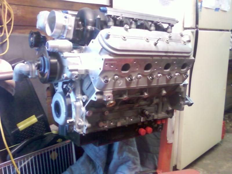
For those not in the know, an L76 is basically an LS2 4.00" bore block with LS3 heads. It was used in a bunch of Holdens, but only the Pontiac G8 state side.
Paying for the big bore block the LS7 heads require was going to slow me down too much, and I got a crazy good deal on the L76, so here we are.
I took some calipers to the ports on the LS3 heads and intake. The plastic intake was as small as 28.9mm accross in the smallest port while the head's port got as large as 31.8mm. It was probably a smart move on GMs part to make sure that there wouldn't be a step down going into the head's intake ports regardless of sloppy tollerances. But obviously there is room to improve by hogging out the plastic intake close to 1mm all around. Normally the LS3 intake uses a nifty re-usable rubber gasket o-rings. Not a lot of help for gasket matching the heads to the intake. I had been told that the carb spyder intakes for the LS3 had gaskets that were too big to be of use also.
I started a thread on the topic here:
Gasket Matching an L76 intake - LS1TECH
But I found a company called SCE that sells gaskets that are smaller than the head ports and are perfect for gasket-matching. The gaskets aren't perfectly square or perfect, but at least they aren't too big.
2/5/11
The LS1 valve covers I have don't clear the offset rockers of the LS3 heads. Trimming the inside divider walls should do the trick, but if you're running a standard PCV set up this can create a lot of oil getting out. I'm running a dry sump with a breather so I'll just seal the valve covers and not worry about it.
I wanted to keep the coils in the stock location to keep the spark plug wires as short as possible. A lot of the coil relocation kits look cool, but I consider them un-functional. The new LS9 valve covers eliminate the coil mounting brackets and bolt the coils straight to the valve covers. But I think it's probably a good idea to get some vibration damping to the coils.
These are pretty!.. Pretty pricey
$180
$260 LS9 covers come with 6 coils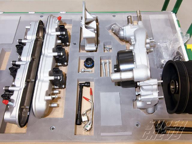
$$$ my fav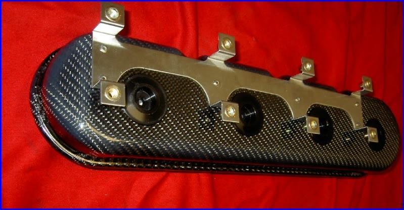
DIY!!! $free!
407 grams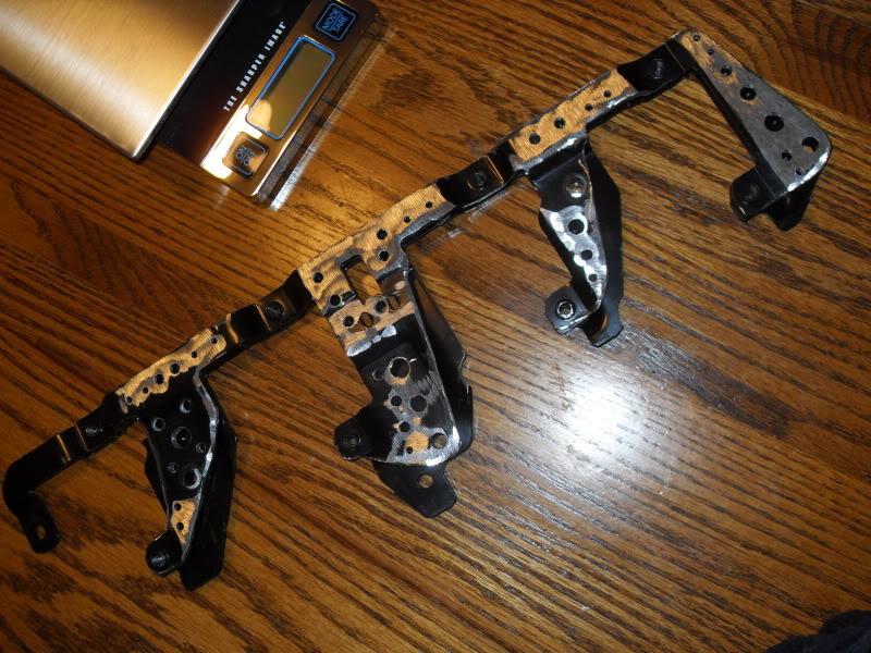
vs OG 599 grams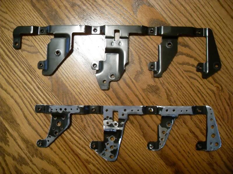
A little polish and paint...
2/22/11
Stockbee asked me for a spring reccomendation. Here's my reply
My question at this point is this: What spring rates are going to be appropriate for the added heft of the car in the front?
Have any recommendations? I've heard you added about 100 lbs to the front of the car but that the rest of the added weight is from the transmission which is centrally located.
I believe that the 240 spring rates shouldn't change even after the addition of an LS1.
The LS1 weighs something under 450 lbs, while both the sr20 with a turbo, and the ka without, each weigh 490. However the T56 is a beast at about 140 lbs, at least 60 lbs more than any of the nissan transmissions. Fortunately the t56 weight sits right in the middle of the car not affecting the chassis balance. My Ohlins came stock with 8 kg/mm in front and 6 in rear.
Here's an example of an LS14
MMDBs corner weights:
"Front driver: 878
Rear driver: 697
Front Passenger: 863
Rear Passenger : 682
55.8% weight in front
44.2% weight in rear
(A stock s14 is 55/45, and with the addition of a driver the s14 will usually shift an entire 1% rearward)
Cross weights within .5% (within ideal, max being 1%)
Total weight including myself in the car with 1/4 tank of gas, no spare tire, and everything else intact (passenger seats etc):
3120
Without me in the car:
2970
A little bit heavier than I anticipated (was thinking 2900 most), but that's with everything in the car minus the spare tire. Also, the battery is located in back of the car as well."
Another LS1/T56 s14 built by Hinson weighed in at 2742 total with no exhaust, and everything stripped out of the trunk.
a S14 weighs 2832 stock. That's 140 less than MMDBs stock LS1/T56 car, and 90 more than Hinsons!
8/6 = 450/337 lbs/in Which sounds low, but you have to remember that the fronts are struts which have exactly a motion ratio of 1:1 and the rear places the coilover outside so far that they also have a motion ratio of 1:1. Most unequal length cars have higher motion ratios and therefore need more spring.
For autocross a lot of people have oversteer problems with an aftermarket front sway and a stock rear. Since the front camber gain sucks with the front strut design I plan on going overkill on the front sway bar to limit travel a bit. In the rear I may go even softer so that I can run a decent sway bar in the rear. Sway bars equalize traction on acceleration in the rear. A lot of guys just completely remove the rear sway, but in a high hp car I don’t think it’s the way to go.
For road course or drift-use you can definitely run stiffer springs. Most guys that have tried anything over 10 (564) in the front usually go back down.
MMDBs 2900 lbs may sound like a lot but There's almost 400 lbs he could ditch if he wanted to.
Weight Reduction-
A/C 30
Trunk lining 3
Carpet padding and tar- 30
Interior plastic and headliner 10
Sunroof 24
Steering wheel 6
Pass Air bag 8
Body Panels
Hood 40
Trunk 10
Battery- 25
Wheels 2lb x4 8
Spare tire and jack 30
Seats front 50
Seats Rear 39
Bumpers and tow hooks- 80
Body Holes & hardware 10
403 lbs.
There's no reason an LS14 couldn't get below 2600 lbs dry. With a cage and massive wheels I'm hoping to hit low 2700s.
I'd start with 8/6 like the Ohlins
maybe 5 in the rear for autocross or street
or 9 in front for dedicated track
3/18/11
I have an alternator out of an '06 GTO, and it's heavy! I wanted to get it as low as possible, so I came up with this contraption.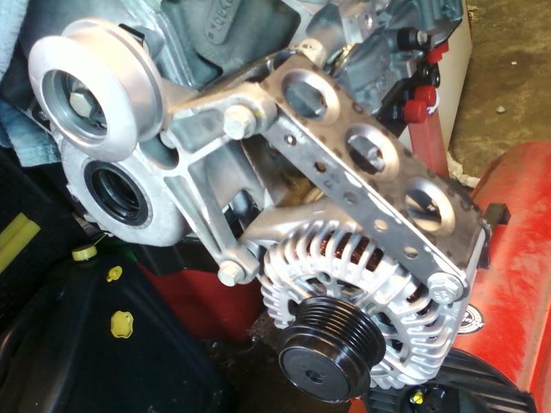
Then I had to clearance the motor plate a bit.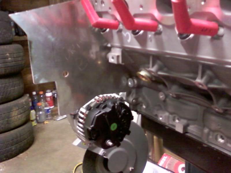
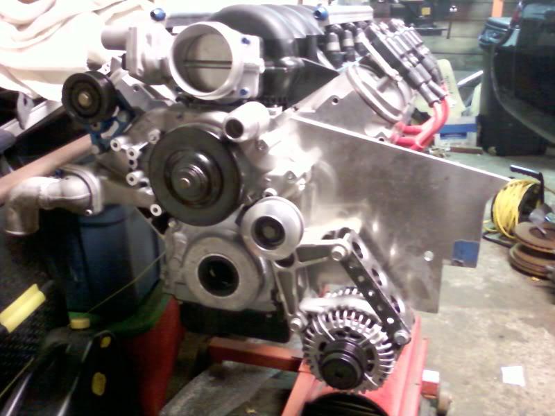
5/5/11
I originally bought this fancy, new, high-torque, MSD starter. It was supposed to be adjustable. But every adjustment hole just moved the reduction motor out further in the way! My header secondaries are 2" OD, and I needed the header to be almost no wider than the starter mounting bolts. Found a 2008 Avalanche 5.3 starter that looked like it might fit the bill. At $180 less than the MSD it seemed like it would be worth a shot. It works perfect!
Manufacturer Part Number: 6494NSurface Finish: Painted/MetalInterchange Part Number: 89017440, 89018123, 8000288, 88861935Warranty: YesOther Part Number: 89017440, 9000939, 8000045, 8000150
The pretty 3 hp MSD starter that doesn't work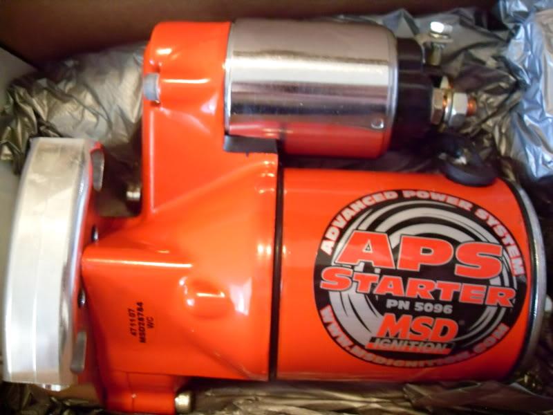
Here's the one I bought. Hopefully it won't get tired on my hi compression stroker motor. It gains me at least 5/16" of clearance over the MSD starter!
Starter Family: Delco PG260D
Type: PMGR
Voltage: 12 Volts
kW: 1.2 kW = 1.63 hp
Rotation: CW
Teeth/Splines: 9 Teeth/Splines
Pinion/Splines OD: 25.2mm / 0.992in
Mounting Hole 1: 10mm ID Unthreaded
Mounting Hole 2: 10mm ID Unthreaded
Approximate Weight: 7.5 lbs / 3.41 kg
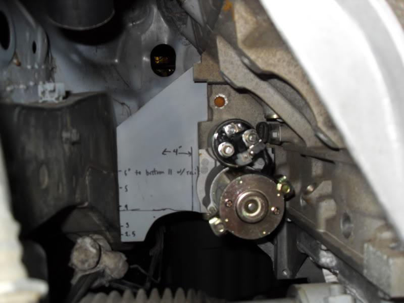
And a little progress on the lower radiator mounts: I welded a stock s14 upper radiator mount below the powerbrace. Then welded 10mm rod to the bottom of the radiator that the stock upper mount style grommets fit onto. This will locate the radiator bottom in every direction, other than vertical.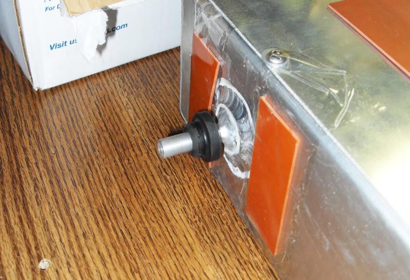
I like drilling holes in things.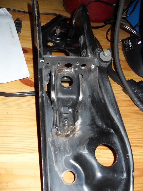
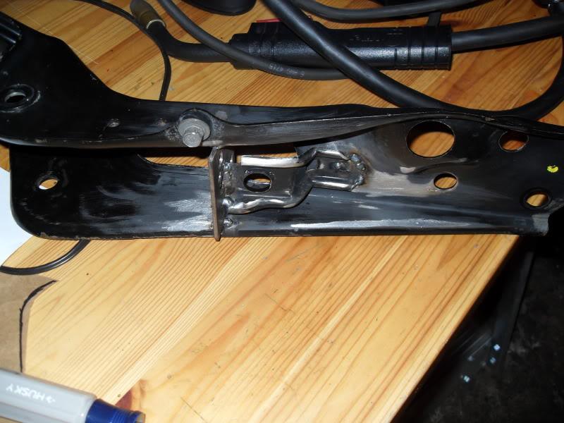
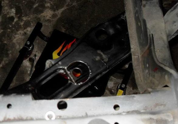
The weather is finally decent, so I'm going to re-start my rear subframe reinforcement project soon.
I have a bunch of stuff that I want to paint the back of BEFORE I weld. What do you guys use? I've heard of guys using BBQ grill paint, and header paint... Any suggestions?
5/17/11
Rolled some fenders for some friends last night. My buddy scored a set of 18x10.5 +15 TE37s. He is running KYB AGX dampers which are a good bit more narrow than most coilovers, but he still had 26.8mm of clearance to the dampers! That means 18x10.5s could have +41mm of offset without hitting narrower dampers!!! Or you could run the same front space and still fit 18x11.5s. These pics are from before we did a little pull, but he had already rolled a bit. And he maxed out the camber of the stock arms, 2+ degrees of camber I'm guessing.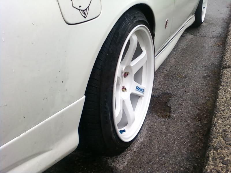
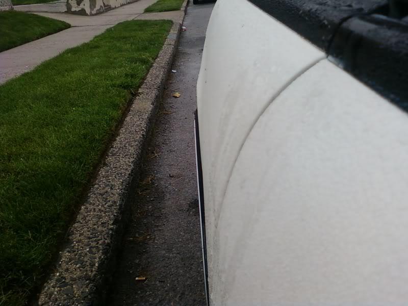
26.8mm clearance. His 245s look like dangerous stretch to me.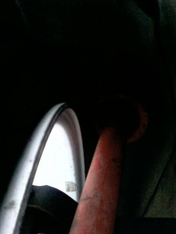
5/23/11
I've been a little concerned about using the manley pistons that I have with the oliver rods that I have. Originally I was going to custom order some low compression height Wiseco pistons, but the long block parts I got were just too good to pass up. My pistons have a standard compression height designed to be used with what has become the LSX standard 6.125" aftermarket rod. My oliver rods with the lube tubes are 6.200".
The taller rods necessitate a taller gasket. A stock LS7 gasket is 0.054" thick compressed. With the taller rods (presuming all of my measurements are exactly as advertised... unlikely) I'd need a 0.105" tall head gasket. Cometic stocks up to 0.125"! To put that into perspective for the import guys that's 3.2 mm thick!
Found this here on ls1tech about variances in LS2 deck heights by ChucksZ06 back in 2006
Piston Deck Height for stock LS2 [Archive] - LS1TECH
"My first ls2 block with 4" eagle crank and rods was .005 in the hole. I am now doing an ls2 block with a stock crank and 6.125 rods( same length as 402 build), same piston manufacturer and the pistons are .008 out. I think the stroke on the 4" crank was not quite right. So from my experience you pretty much have to mock up the parts or it is guessing. Good luck."
Keeping the top ring below deck seems like common sense. It's common for the crevice height (top of piston to top of top ring) on performance pistons to range from about 0.180 - 0.320". So presuming (what I consider) a loose quench of 0.035" and super tall 0.125" gasket you should still be safe with low crevice volume pistons all the way down to a crevice height of 0.160". Still that's a little too close if you're running a low crevice height pistons near 0.180".
9.240" stock LS1/2/3/7 Deck height
2.000" less 4" stroke/2
1.115" less my manley piston's compression height (was designed for a 6.125" rod)
6.200" less my lube-tube oliver pistons
puts me 0.075" out of the hole.
for a tight 0.030" quench I'd need a custom 0.105" thick gasket.
I also found Lingenfelters book on google. He mentions that he reccomends 0.250 crevice height for street engines, but has seen all the way down to 0.100" on all out N/A drag engines!
Good read:
John Lingenfelter on modifying small-block Chevy engines: high performance ...
By John Lingenfelter
John Lingenfelter on modifying small ... - Google Books
Stock LS3 chambers seem to very quite a bit. Stock blue print is 68.4 +/- 1cc. But in the real world they seem to very from 68.5-70.9cc.
Here's a cam I'm considering having ground that would work with a stock chamber with just a .005" clean up mill to 68cc chambers. This cam has 4 degrees of advanced ground in. I'd like to run a few degrees less advance, but I like the idea of not taking the chambers too small incase I ever want to go forced induction.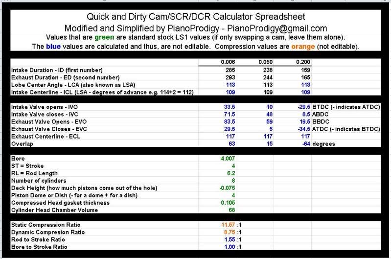
5/27/11
I was pulling apart a Z32 rear subframe and noticed this reinforcement that the s14 doesnt have. Can't decide if it's worth replicating or not.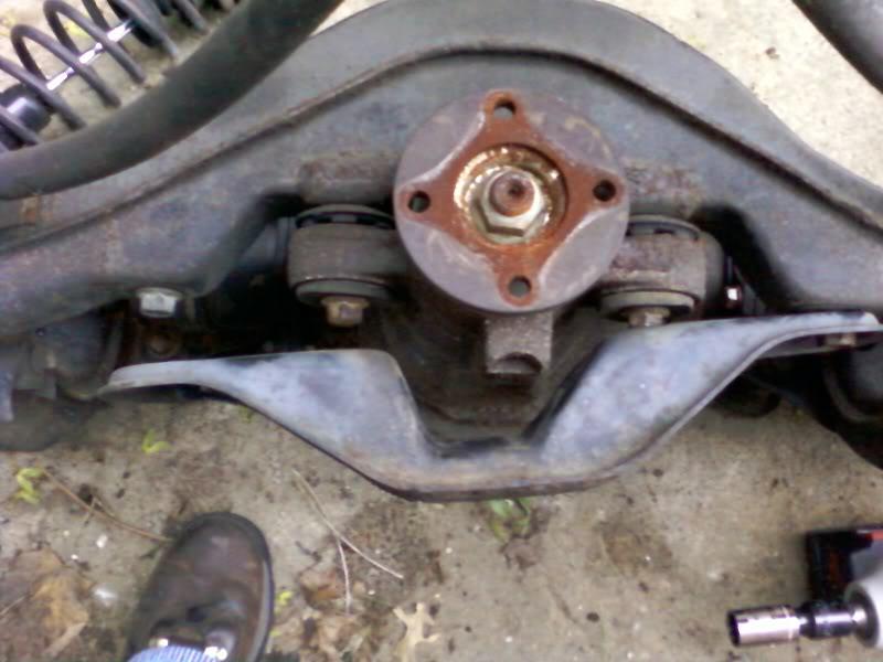
I also scanned the Ohlins instructions manual to pdf files, but they are of course in Japanese and I can't read them. If any one can help, or knows anyone that might be willing to translate them for me, please shoot me a pm and I'll email the pdf files to ya. Thanks guys!
6/9/11
I covered anti squat and the as-engineered state of the s14. Now it's time to take a look at the other end of the car. Anti-dive is just anit-squat turned around backwards. It's calculated pretty much the same way. But for a Mac Strut car like ours with no upper control arm, the instant center is created by the intersection of the line through the lower control arm and a line perpindicular to the the top of the strut.
More caster will get you more anti dive, but very slowly. But even small changes in the FLCA mount (up), or the tension rod (down), will quickly get you more anti squat.
A refresher on on calculating anti dive/squat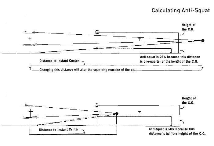
My calcs show the stock s14 with 14.8% anti-dive. My sources say that 20-25% is ideal. For the calcs I used a ground clearance of 3.2", a CG height of 10.65", with 52% front weight bias, and 7 degrees of caster.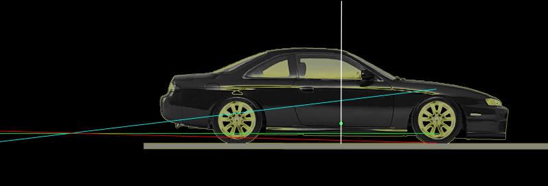
Moving the FLCA mount up 0.665" should get you upto 25%. It's also good for the roll couple.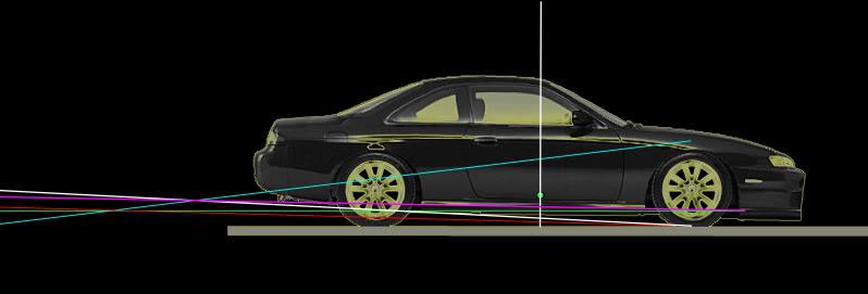
6/10/11
I finally got a chance to play with some suspension software! It's performance trends roll center program. All the measurements came off my s14. I used a ride height of 3.125" from the ground to the bottom of the crossmember. And my LSx crank centerline as the CG height came out to 10.625" above ground. All measuremens also presume 3 degrees of static camber.
Ideal camber curves have about 1 degree of camber gain per degree of roll. The senarios I plotted varied from 0.45 - 0.63 degrees of camber gain. Such is the strut...
Just from visualizing the geometry in my head I expected the set ups with roll center correction to have better and better camber gain as the FLCA angle further down towards the ball joint. This isn't the case! Improving the roll center, hurts camber gain, but not much. Who new?
Before we can get to the nitty gritty of roll couple we need to talk about ball joints. I found this totally sweet pic in the roll center thread. From the pic I extrapolated that the stock ball joint is about 1.5". The whiteline and moonface pieces go for around $270, while the stockers (only 0.69" shorter) go for only $27! 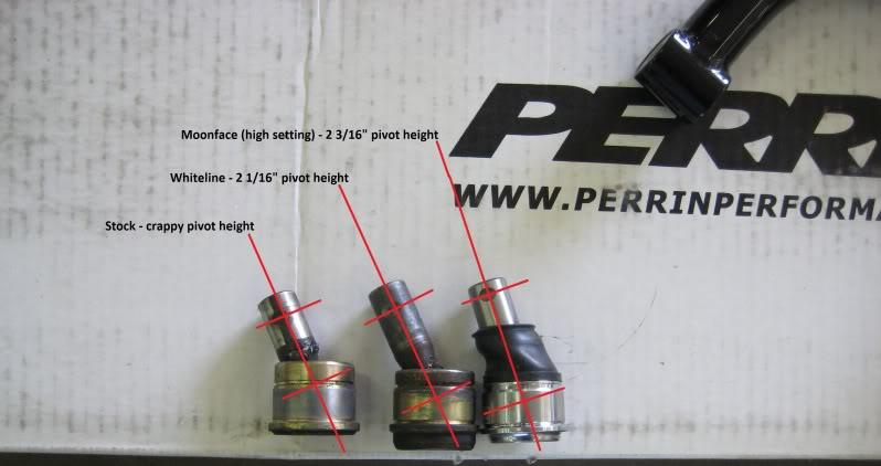
And here's an example of goin all hardcore with the ball joints. But notice that even after all this there's no more correction than the moonface offers. Looks a bit over two inches of from the ball joint articulation to mount. Of course with this kind of set up you can go bigger. But would you want to? Those bolts in single shear start to look real scary real fast.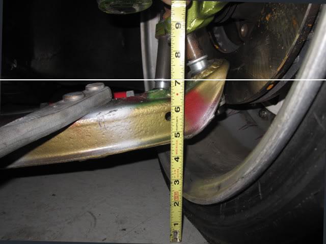
So here's what it looks like without any correction: OPTION 1
roll center 1.5" below ground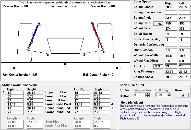
With a ball joint that is >2" long: OPTION 2
you reduce the roll couple by 1.5" (or 14%), and at least the roll center is level with the ground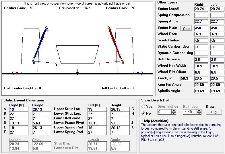
Now if you cut off the bottom of the spindle, and weld in a big block of steel (2.35" tall) above the ball joint spindle taper/mount,
you'll get a lot more correction than the 0.69" that expensive ball joints buys you. A 275/40/17 tire has a 4" all side wall, in the below calc this 2.35" "inner-spindle spacer" puts the articulation at only 5.4" above the ground. This will be damn close to scraping the bottom of your inner wheel!
This Driftworks Geomaster front spindle only has 1.97" or roll center adjustment built in and already looks damy close to these wheels!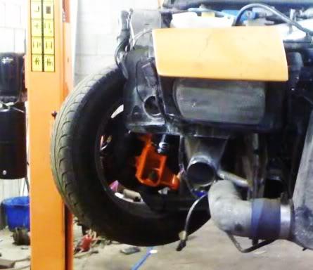
Surprisingly raising the chassis mounting point for the FLCA doesn't do much. But in the following calc it's raised 0.66" just for Anti-Dive.
With these two mods here's what you'll get: OPTION 3
A roll center height of 4.7" above the ground! Thats a roll couple that's been decreased from 12.125 to 5.925, for a roll couple that's only 48% of OPTION 1.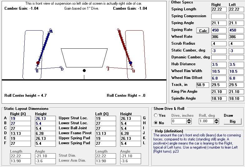
With this final set up: 3.6 degrees of chassis roll only moves the roll center down one inch. Dynamically the only way to get a negative roll couple is to have the front of the car come up >2.7" from static ride height like a wheelie. Honestly I wouldn't mind decreasing the roll couple even more, but I just don't think it's feasable without messing with the Kingpin angle, and that would take so much work that you're better off picking a different chassis or going double a-arm.
And just for shits and giggles. OPTION 4. If you really want the highest roll center, don't change anything! It looks like a stock 240sx with a (STOCK???) ride height of 6" ground clearance has the roll center 5.7" above ground. But of course it also has a center of gravity 3" higher, and a roll couple (what this is really all about) 2" worse than OPTION 3.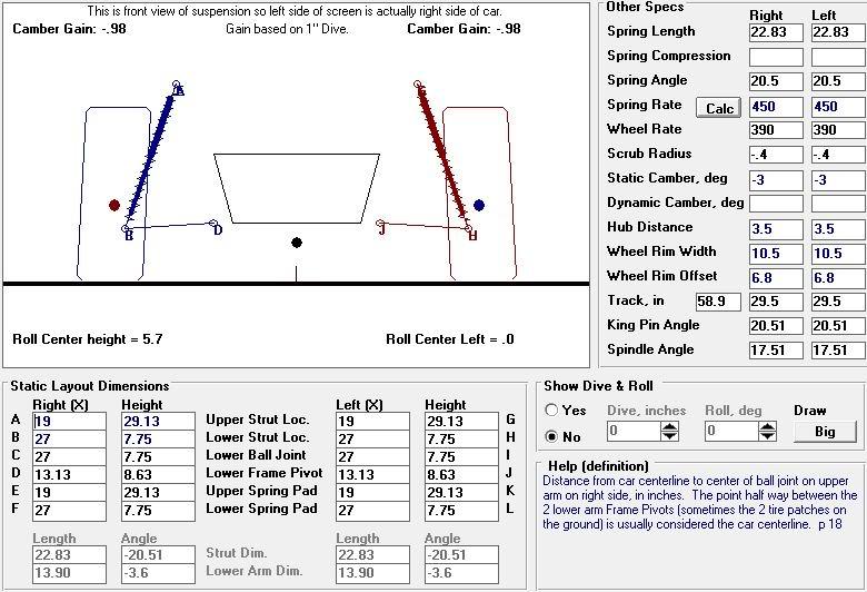
Knoop,
2700 with cage and our stock depleted uranium hood!? That's awesome to hear. And your new paint looks epic, I have to be honest, I never expected the fenders to turn out that bitchin. Cutting the inner rear fender-well in back, and trailer fenders in front was brilliant!
How much weight did you save with your custom front bumper? I was checking out the stock front bumper, and was wondering how much wieght could really be saved?
Re. the ball joints. I think that the moonface articulation point is is almost a full inch higher compared your custom/adjustable ball joints in relation to the top of the FLCA. Which probably robs some
Megan on left LOL. Stock on right, with articulation point above FLCA.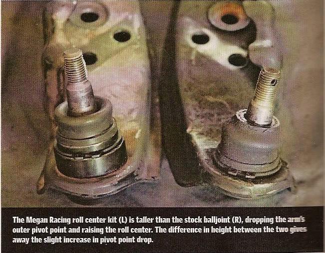
Knoops sweet custom set-up, with articulation point level with FLCA top.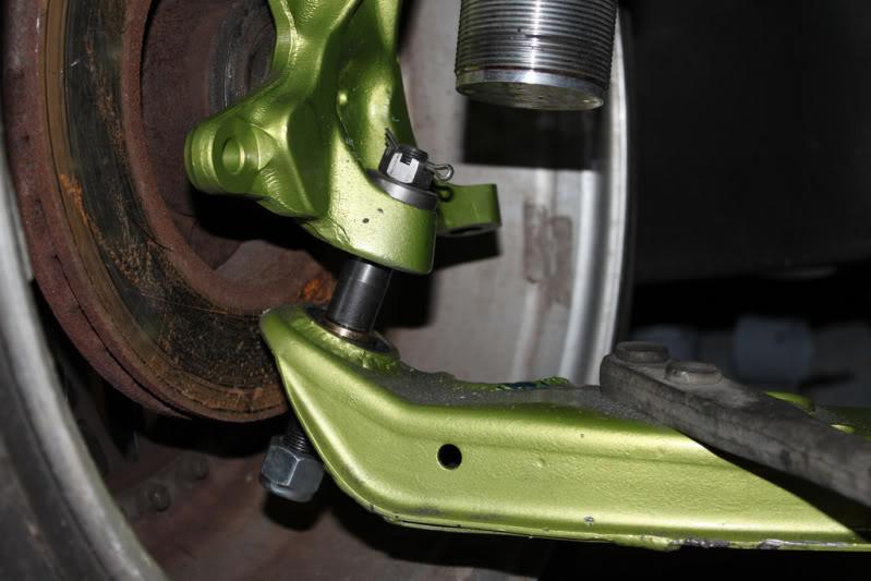
6/27/11
I stumbled accross these gussets the other day. I think my roll cage Neeeeds them...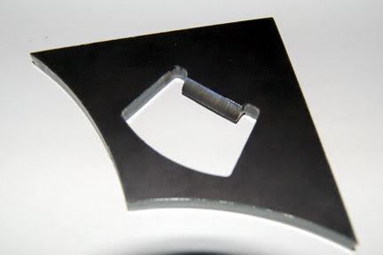
available here
TMR Customs, Custom Fabrication Components for Offroad Vehicles
6/30/11
HioSSilver over on LS1tech has been running a 4th gen camaro with a multi-plate racing clutch + crate ls6 and doing 11.53 @ 122 1.90 60' (on 18's) with only 413 rwhp & 395 rwtq!! You'll notice his 60' is nothing special, I've seen plenty of Nissans do 1.60 60'. I think part of the explination for his awesome et per hp is due to the clutch's low MOI (moment of inertia).
Here's a pic of his Tilton 5.5" triple racing clutch bolted to a button plate that is sandwiched between a stock auto flexplate and the clutch.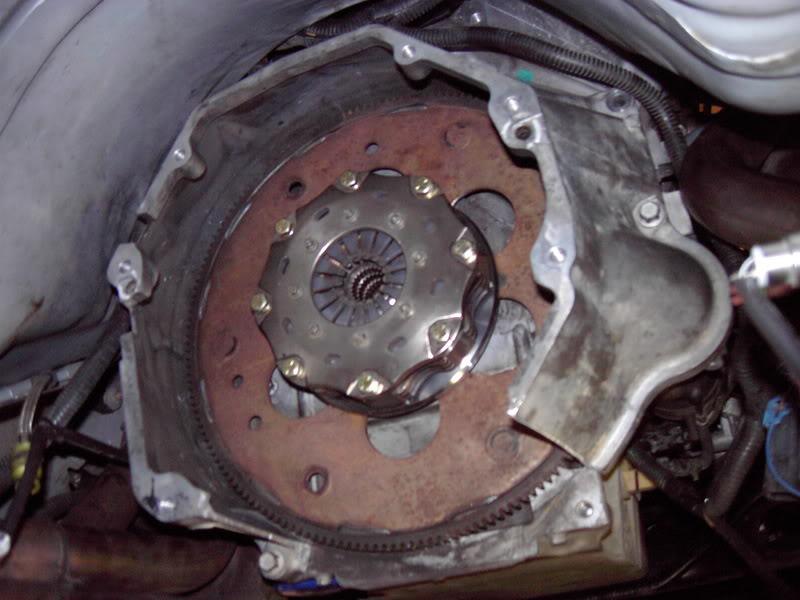
I sent him a PM
"Been doing a bit more research on racing clutches in street cars, and was wondering if your 5.5 is still alive?"
"Yes it is. The first set of clutches (new) lasted 2.5 yrs. The next set lasted 1.5 yrs (used) and the set in it now is used 6mths. This is my dd. I really like this set-up. It cures all that clutch bullshit evryone goes through."
In a thread he posted about it he said his GF can even drive it!
And a pic of a Zoom flywheel for an LS1 (left) next to a stock iron LS1 flywheel (right), (they are the same size, both with 153 teeth for starter engagement). The zoom flywheel can accomidate upto a full 12" clutch disc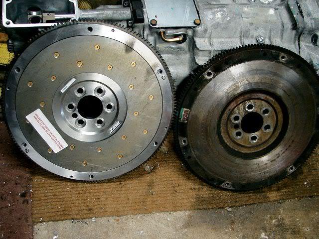
Here's a list of the MOI of different clutches
Tilton Clutch Assemblies MOI (lb-in^2)
Includes: Clutch cover with diaphragm spring, pressure plates and floater plate(s)
(add 66 MOI and 2.5# to include the button
(add 87 MOI and 3.4# to include a Sonic ultra-lightweight flexplate)
13 4.4â€Â Tilton carbon carbon 4 disc
21.4 5.5â€Â Tilton 1 disc cerametallic
29.4 5.5â€Â Tilton 2 disc sintered metallic (6#)
32.2 5.5â€Â Tilton 2 disc cerametallic
52.4 7.25â€Â Tilton 1 disc cerametallic
76.3 7.25â€Â Tilton 2 disc cerametallic
89.6 7.25â€Â Tilton 3 disc sintered metallic (10.2#)
99 8.5â€Â Tilton 1 disc cerametallic
100.2 7.25â€Â Tilton 3 disc cerametallic
158 8.5â€Â Tilton 2 disc cerametallic
337 9.0â€Â Mantic street dual sprung clutch (33.8#) cool set up!
>3200 11.5"? Stock LS2 flywheel and clutch (52#)
A good rule of thumb with racing clutches is that doubling a clutches weight will double its MOI, but doubling its diameter increase the MOI 4 times! Another rule of thumb is that increasing the clutches diameter 1.1" doubles the MOI.P
Here's PTTs set up. I was all excited because they were one of the first to introduce organic discs in race car, multi-plate sizes. But I spoke to their rep today who informed me that they don't reccomend their organic discs on any car over 400 hp regardless of how many discs. Bums me out, but maybe I'll call and talk to one of their engineers.
the "button" looks bigger in the pic than it actually is. It's inner 6 bolt holes line up with the flexplate's (flywheel for an automatic car)inner 6 bolt holes .
KH3049 goes for $812 + $263 for there small diameter through out bearing = $1075
7/9/11
Had a nice little trip last week!
At first I was considering getting a 32 gallon, cause some day I'd like to go E85 which suck a TON of fuel. But I was worried about being able to get it out from the top of trunk. ATL makes a "shoebox" style container that has no flanges, so it's easier to drop from the bottom. Turns out the 32 doesn't come with a shoe box lid. The 32 was going to be pretty damn tall (would have almost hit he trunk torsion springs) anyways. The aluminum containers are supposed to only weigh 15 lbs compared to about 25 lbs for the steel.
So I got the 22B!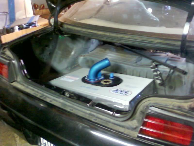
The 22B even fits from the top with no problem. So the shoe box lid wasn't needed.
The Nascar surplus ATL lid I scored on ebay came with a huge 1.5" vent tube, which is absolutely unneccesary unless you plan on doing speed fueling refills. Otherwise a vent as small as AN-6 with a check ball (for roll-over) will sufice.
I read on more than one forum that fuel cells with very large vents can evaporate enough fuel to empty a small tank over a few months. The guys at ATL thought that was bull-shit. Either way I was reading up on fuel vents. The stock system routes a small hose (probably ~3/8") to the charcoal canister mounted just infront of the passenger side rear bumper. The idea is that all of the fuel fumes get trapped there while the car is not running. A second (equally small) hose connects the other side of the charcoal cannister to the intake manifold. When the car is started, all of the stored fuel vapor is sucked into the combustion chamber via running vacuum. The charcoal canister weighs almost nothing, and is supposed to last the life of the vehicle. I am considerng installing a -6 check valve back to the original charcoal canister. And placing a fuel level sender where the 1.5" vent is.
The orignal ATL fuel level sender is non-mechanical. It is called a capasitive sender. They can be made almost any length, and can be set u for any resistive range to match different stock gauges. However, they have to be calibrated to one specific fuel type. A gauge set up for gasoline, will not read correctly once you pour in E85. ATL's newer gauge type is about $40 more expansive, is mechanical, has a set ohm range, and reads accurately regardless of fuel type. The fuel level senders are about the same diameter flange as my 1.5" nascar vent but the level senders have a 5 bolt pattern compared to the vents 8 bolt. 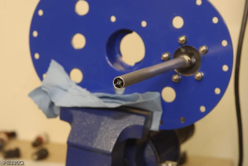
Above is an example of a capacitance type level sender. it measures the resistance between the center probe and outer tube.
7/10/11
Got my hands on Engine Analyzer Pro software. Seriously cool program. I have a top of the line i7 processor and 6 gigs of ram, and the computations can still take upto a minute every time I try and get it to run a combo! Crazy. I've been playing with options on my 404 with LS3 heads. Originally, after a lot of research I settled on a 238/244 cam. After playing wiht the new software that may change a bit. Here's some interesting things I learned while playing with the software:
1) don't need more than .604 exhaust lift
2) I'm not willing to loose >60 ft lbs of torque below 4000 rpm with a tunnel ram intake even if it gains me 50 hp up top.
3) decreasing intake duration from 238->232 lowers avg hp 1
4) increasing intake duration from 238->244 lowers avg trq 2
5) the only change w a big 90mmX1" spacer is a loss of 1 hp!
One thing that I was really interested in was exhaust valve duration. The LS3 heads are very unique in the world of modern performance heads in that the exhaust only flow 66.5% of what the intakes flow. This is considered pretty low. Unless you're talking about a modern Winston cup car. All of Comp cams off-the-shelf LS3 cams try to "overcome" the relatively poor exhaust flow by running a huge 15 degrees more duration on the exhuast lobe than the intake lobes. Normally this would be considered excessive on onything short of a full blown nitrous motor. And really didn't make sense to me.
My intake duration 238 + 15 = 253
I did multiple tests on the simulator. I would always add the extra duration to the exhaust opening in my tests, so not to change the overlap. And with comps 15 degree split I would loose between 5 and 15 ft lbs below 5000 rpm. In one simulation I lost 50 ft lbs at 3500 rpm with the greater exhaust duration! And I usually only gained 5-7 hp over 6000 rpm.
Then I thought maybe even my split was too much. My proposed 238-244= 6 degrees of split. Dropping down to only 3 degrees of split with a 241 exhaust duration picked up a huge 13 ft lbs at 3500 rpm and only gave up 1-2 hp above 5500 rpm.
Here's the Winner cam as of right now.
238/240 112 +1 .612 lift in and ex
max trq 570 @5000, 479 avg 2500-7000 rpm
max hp 600 @6000, 436 avg 2500-7000 rpm
Every one warned me not to get my hopes up over 6300 rpm with the stock intake. And boy the Engine Analyzer doesn't disagree! This thing just falls on its FACE over 6500 rpm. But with an AVERAGE of 480 ft-lbs!!! everywhere, my heart's not exactly broken up about it.
Here's an example dyno plot produced by the program. These would be engine dyno numbers with a 300 rpm/sec accel rate, and with all accessories and a flywheel. Here the cam is retarded to -1 (+4 has almost become the standard in the LS world)! It trades 4 ft lbs down low for 5 hp up top compared to my +1 cam (that is 2 degrees more advanced).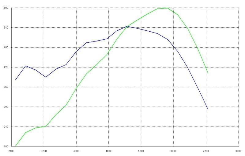
My only complaint about the Performance Trends Engine Anaylyzer software would be it's exhaust system inputs. There's no way to compare try-y to 4-1 headers, which work on completely contradictory reflective wave ideas. The software will only let you input just primary diameter and primary length. I combined my primary and secondary lengths (tri-y) to get a primary diameter for performance trends. Fortunately I also have Larry Meraux's "Pipe Max" software, which goes into minute detail on the entire exhaust system.
8/27/11
Got a little work done on the rear subframe yesterday. I noticed that even without an upper bushing in the front frame attachment points, that the subframe was contacting the car frame on the lip around the tube/cup that used to house the stock bushings (where everyone puts the collars). I still want to raise the rear roll center a bit, so raising the front of the subframe with no upper bushing makes sense. But raising the whole subframe up for a little free roll center correction is a massive bonus. The cup lip sits about 6mm higher than the rest of the subframe. The stock subframe bushings sit about 10mm higher than the cups in the rear and about 15mm higher in front. I've reduced that to about 2 mm in the rear and -6 in the front now for a total roll center correction of ~15mm (-8mmR and -21mmF)!. That's like installing drop knuckles! Even if it is less than an inch. Drop knuckles...$1100 Dead Grinding wheel... $3
Stock S13 bushing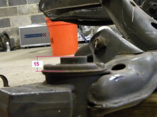
My front S14 subframe less stock bushing but pre hackery. Notice the ~6mm step to the top of the cup even without a bushing.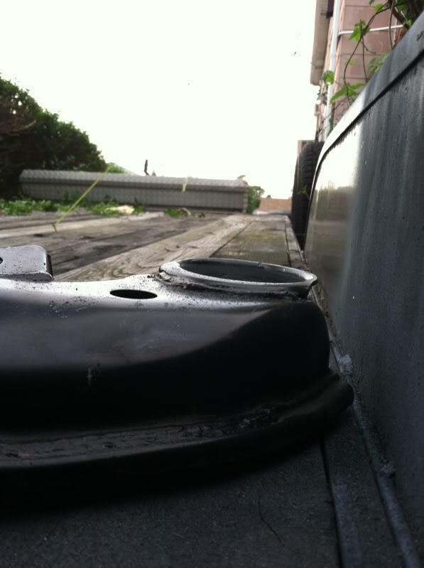
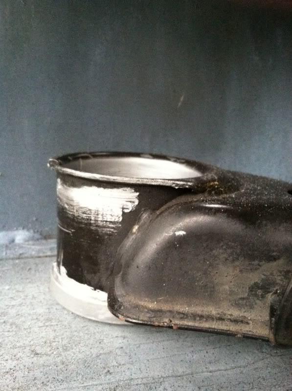
Post Grinding. I'll probably throw a bead in there to make up for what I took off.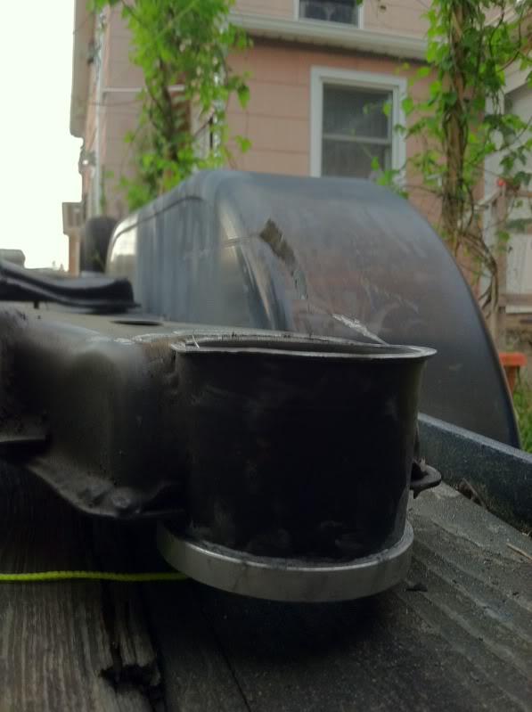
11/13/12
I'm living in NYC now and to get to my garage in Long Island (only 17 miles away) takes walking a total of 3 miles, 18 stops on the F train, and 45 minutes on a bus. 2:15 each way...
Made the trek yesterday and got a little bit of ugly welding done on my subframe. It penetrated and will hold. That's all that matters right?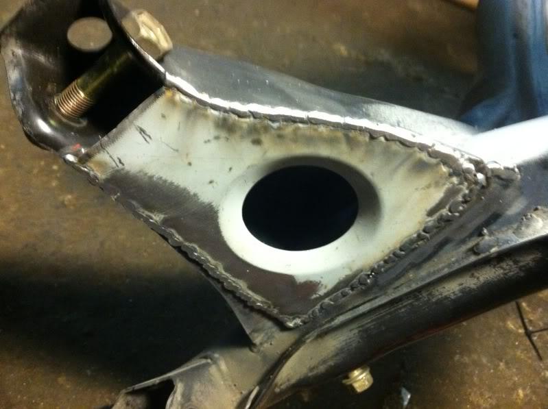
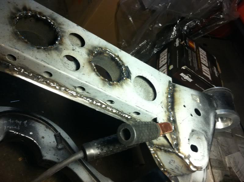
11/22/11
I bought a custom kit on NRR to make my own toe and traction rods. The kit only requires you to come up with threaded rod and heim joints. Here's one of the kits assembled, traction rods with steel hex.
I was going to go with threaded 7/8" aluminum hex (like the original battle versions), but then the other day I noticed that coleman racing has a new part:
Trailing Arm, Ez-Just - Racing Parts and Products
I like that you get an extra 1/2" of thread engagement per side (even if the tube is split) because you're not using jam nuts.
I was a little confused because the thread sizes are not listed at Coleman. FYI: The trailing arms are 3/4" L&R thread, the tie rod arms are 5/8" thread. At ~$20 ea they are almost twice the price of hex rod, but still not a bad deal. I asked for QA1 rod ends for Christmas, so I might have this rear subframe all together in a few months.
11/30/11
Is it just me or do these MAX tension rods have a striking similarity to the coleman pieces?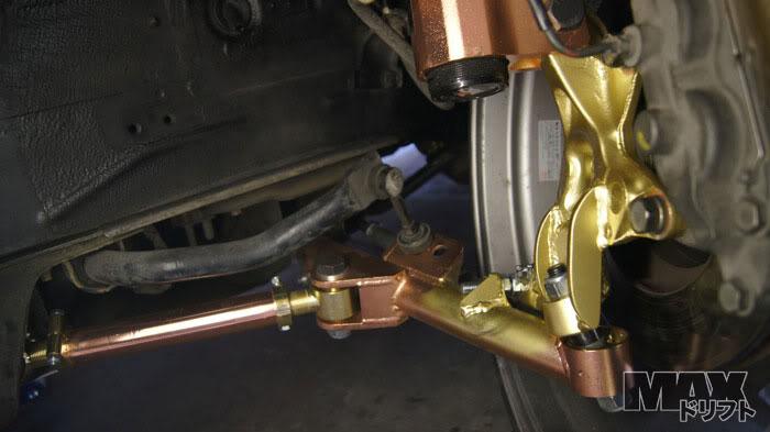
Now that I look at it the threads on the max part look like at least 0.75", and the clamp looks more beefy too. BTW, mad props to MAX for the most elegantly/functional/lightweight modified stock knuckles I've ever seen! I love it!
12/2/11
I've had a lot of trouble getting center of gravity heights. It seems that no one in the nissan world has ever gone through the bother of measuring. But I just heard the quoted CG height of the newish toyobaru GT86 wich has a "low center of gravity of 475mm".
FYI for those messing with their roll-couple calculations. But I think I can do better. We'll see.
That's 18.7"
1/20/12
Here's a pic of some of the sizes of Toyo RA1s I'm considering.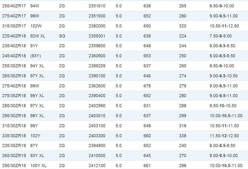
I originally went with the 275/40/17 (d=652mm) Azenis cuz they are about the shortest/widest/cheapest thing I could find. But lookin towards the future, check out those 315/30/18s (d=648mm)! They're even shorter than my 275s! And the 285/30/18s (d=631mm) are the shortest tires on the whole list, even shorter than the 255/40/17s (d=638mm)that I'm runnin on the front right now!
Now there is always a big (seriously, it's not cool) jump in tire cost going from 17s to 18s, so why is it worth it? A big double whammy of lower CG OR better roll centers (given the same ride height).
You have to devide the tires outer diameter by pi to get their height. And swapping my front 255/40/17 (d=652mm) for the wider/shorter 285/30/18s (d=631mm) would lower my tire height 652mm/pi-631mm/pi= 207.54mm-200.85mm = 6.68mm = 0.263"
The spindle is lowered by half the difference of the tire heights. So 0.263"/2 = 0.132". That's a bit more than an eighth of an inch of roll center correction or better CG, just for changing tires from a skinnier 255/17 to the lower profile 285/18!
Of course it would be even sweeter if they made 30 series 17" rubber, or better yet 15" rubber in something wider than a 225. But nobody does. So if you can afford it. Step up to 18s.
2/15/12
I scored $500 of dry sump tank for $135 shipped on ebay! And it even showed up undamaged!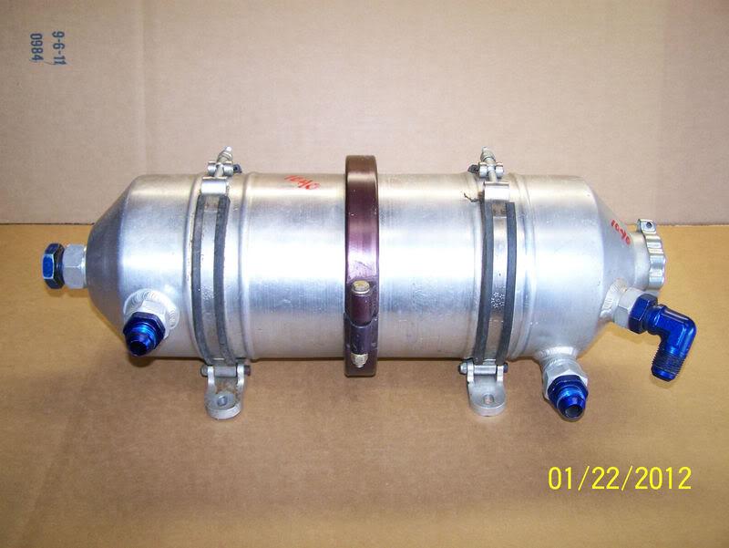
I've been stalking these things forever, but the Nascar surpluss are always 9" or 13" in diameter and usually closer to 4 gallons. This tank is 6"dx21"h and 2.25 gallons. A full gallon bigger than the stock Zo6 tank. That extra 2 gallons in most of the Nascar tanks is 16 lbs and $80/oil change that I don't need. Now I just need to see if I can squeeze that tank in the trunk with my giant 22gallon fuel cell. Cross your fingers for me! The tank is really light at less than 7 lbs dry, but wet it'll be closer to 23lbs. I really don't want that weight in the front of the car. Nor do I want 2+ gallons of 220F oil in the driver compartment, but I may have no choice.
I also got the parts for some of my home-made rear control arms, I'll have a post on those next week.
And in other news, I got engaged, and my homees and I are trying to plan a road-trip/bachelor party from LA, through Vegas, and onto Bonneville for Speedweek! It's August 11-17th this year. I'm hoping the 240 will be done for speedweek 2013. But this year maybe I can make a few licensing runs in a rental!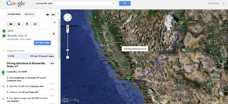
3/4/12
I was worried that there wouldn't be room for the ATL 22b fuel cell AND the dry sump tank both in the trunk. There actually is room to have both the dry sump tank and my huge fuel cell in the trunk even with the fuel cell centered. For cross weight balance it might be beneficial to have the fuel cell offset a little but then my cross weights will change as fuel is used. I guess that's true even if it's centered! What do you guys think?
Lots of room. On both sides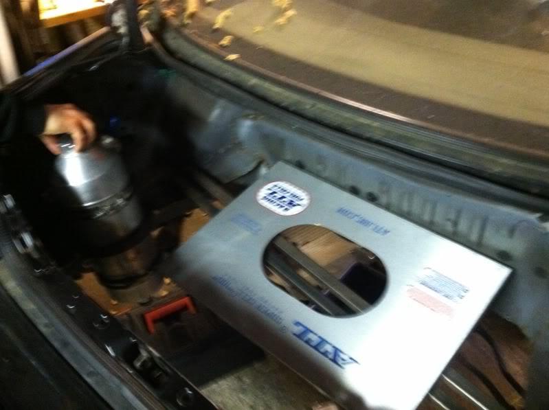
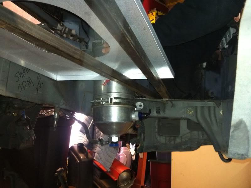
My DIY toe and traction rods are complete too.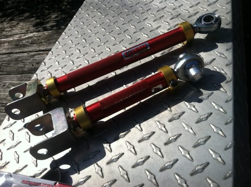
I've been rethinking a few things too. Originally I was going to raise the fuel cell a few inches so that I could start the diffuser at the rear center axle, but now I'm thinking that extra rear downforce is easy to get with a bit more wing, but a lower CG you have to really fight for. So the fuel cell is going to drop a bit, and the diffuser ramp will have to start a little later.
Here's the solution that the famous BRE came up with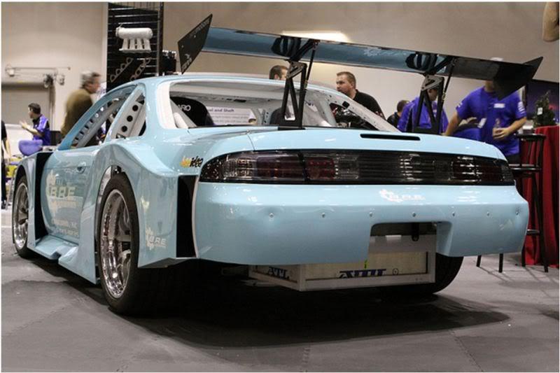
that huge thing where the rear passenger side seat used to be is a box to hold the dry sump. Definitely a lower PMOI than my trunk solution, but with corner exit and balance in the sweepers a greater priority in my time attack (not autocross) car, I think the better weight distribution in the trunk is the way to go. Plus it's a little less butchering, and a little less weight.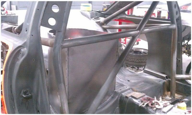
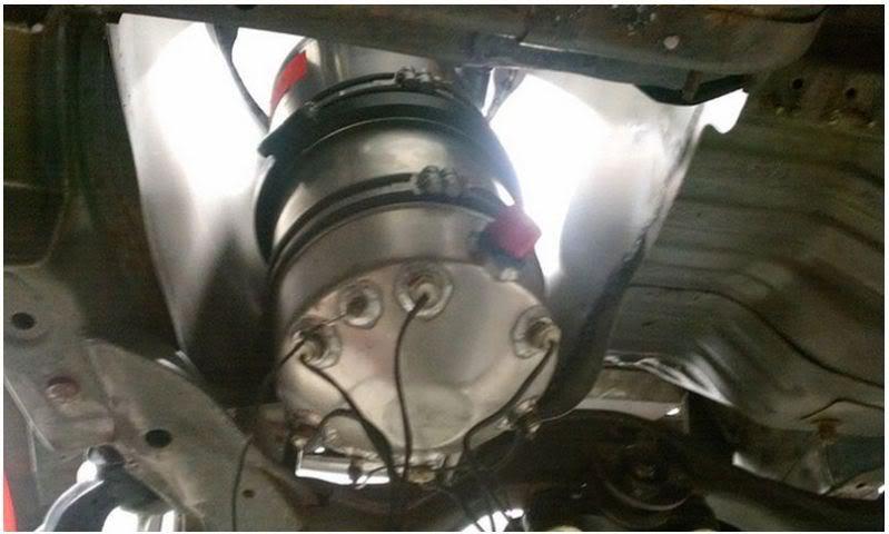
4/9/12
Anybody going to the NYC auto show this week?
I've spent another 2 days or so working on the rear subframe... Feels like it's never going to end.
In other news I may be replacing my custom/OMP extended shifter with this:
My Uncle goes into surgery later this month for a replacement, and I have first dibs on the old one!
6/11/12
I'm trying to get my steering hooked up so I can get the car on the trailer. The universal joint had a notchy feel to it so at $80 I bought a new OEM Nissan universal joint, only to find that it too is notchy . I've had everything apart multiple times. But now I can't get the steering shaft to slide far enough into the universal joint. I've triple checked everything I can think of. This car/chassis has never been raced or crashed.
1. The steering shaft is solidly bolted to the firewall
2. The steering rack bushings are in and look good.
3. The front crossmember is not spaced and bolted in solidly
It looks like I need the shaft/column to come another full inch towards the rack!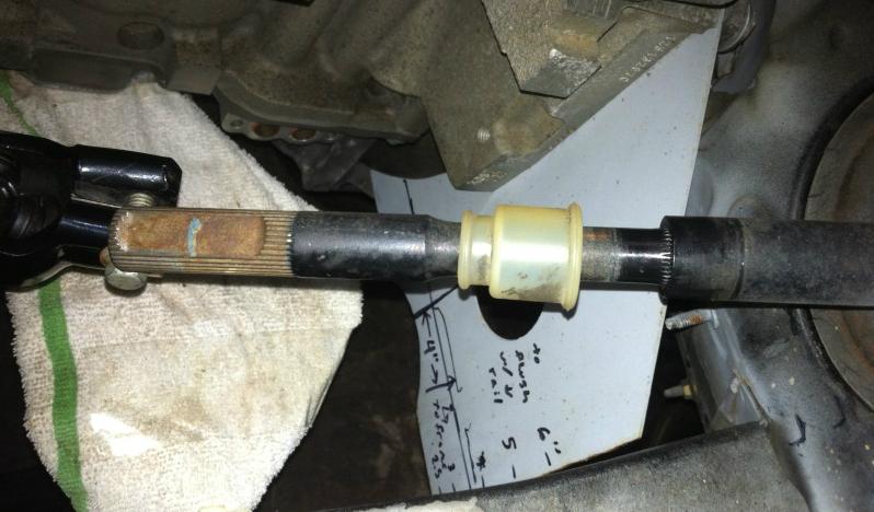
The only thing I can think of is that perhaps I inadvertantly collapsed the steering shaft; I had it standing on end while it was out of the car. But I pulled on it as hard as I could (no jokes plz) and it doesn't move. I pulled down that white rubber looking boot and it looks like there are some splines there. Is that where the column collapses? Any other ideas?
Just a side note. I weighed the steering shaft while it was out of the car and it is surprisingly heavy at 24 lbs. I'd love to replace it with an aluminum racing shaft, but that isn't in the budget right now.
Walperstyle it feels slow but consistent. If not for limited funds I feel like I'd be a lot further along, but at least I still have the car! I see so many projects that I really dig end up for sale, it always bums me out. I love the sound of a turbo, but I just don't want to live without the throttle response and instant torque anymore. If the KA-T isn't what you really are in love with ebay is great for un-pot-commiting yourself (I had to look that up in the urban dictionary).
I have put absolute cubic-hours into the rear subframe. I'm stoked on the roll correction, but I have no idea if the rest of the reinforcements were really necessary. Either way, after all the removing of extraneous brackets and grinding, I think that the gussets ended up weight neutral. I had to wrap it up fast though so that I could put the rear wheels back on the car so I can get it on the trailer for the move coming up this month.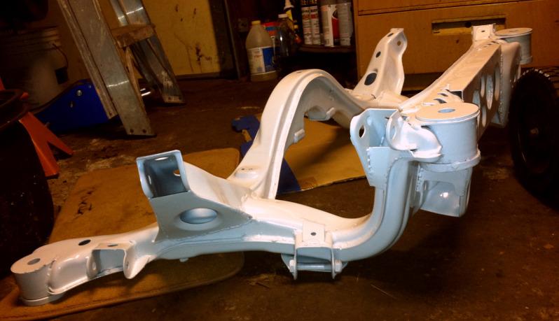
If anybody else is considering making the same modifications to the front subframe mounts, I think it's really important to lay a bead along the top of the cup. All the grinding completely removes the weld holding the top of the cup to the subframe.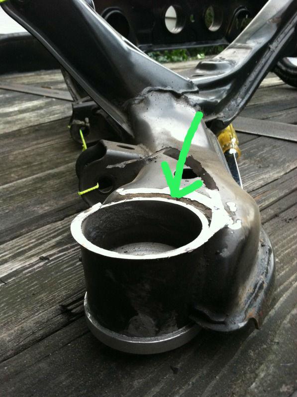
Talk about an easy way to loose 16 lbs!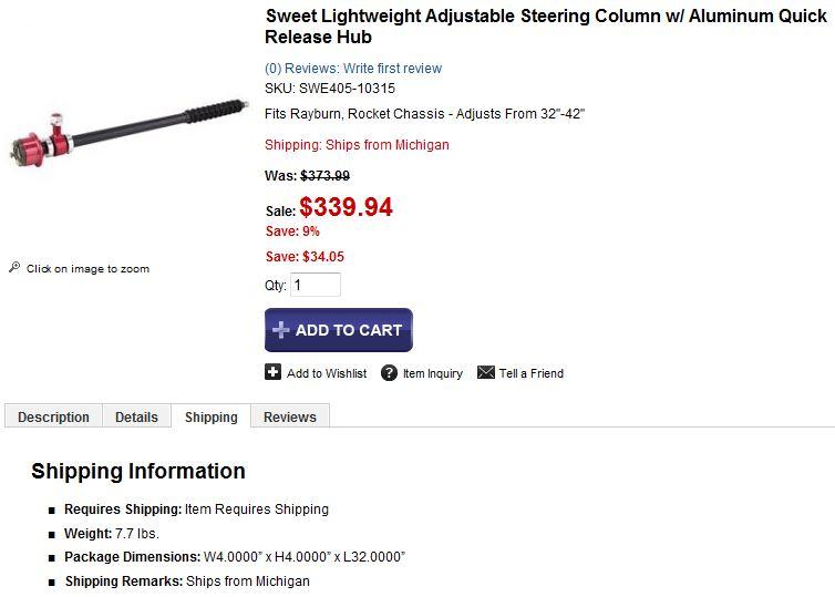
Not to mention the steering wheel itself. My Airbag S14 steering wheel feels like it weighs 5 times more than my Sparco.
6/18/12
Dudes it was not a great day in hot rod land.
So todays goals were:
1. fix the rot on the trailer
2. install the rear subframe
3. un-collapse the steering column
Everything started off well enough while I was repairing the rotten wood in my trailer. Then I got tired of being in the sun and thought, "lets slam that rear subframe up in'der."
My arm just came out of a cast so my Bro Steven gets on the crawler. The back subframe bushings are going on easy enough, but the fronts are really fighting us. He was holding the subframe in, but I couldn't find the bolts right then. And we figured it was such a tight fit, it would stay up there (anyone see where this is going?). Of course while wailing on the front bushings with the BFH, the rear dropped off and the whole subframe came falling down on Steven. It happened so fast, and from where I was (in the wheel well) it looked like the whole damn thing came down on his face! Turns out the clearance hump for the front of the differential provided just the lucky clearance his face needed, and his left arm actually got the most of it. Just a small scrape and bruise. But it didn't get any better from there. We F'd with the rear subframe for another 40 minutes and just couldn't get those front bushings on. I even heated the aluminum bushings with the torch... no dice (but that rustoleum didn't even flinch! I'm impressed). Gave up with a few threads on the nuts on the rear bushings and the front still hopeless even after all the persuasion my BFH had. I don't get it? I've had the subframe on before without all the bushings other than the top front ones. Maybe they are a bit smaller??? I'll put the calliper to 'em next trip.
Then after I had given up on the rear subframe I thought I'd address the steering shaft that seems to be a bit short. I put penetrating oil on it the second I got to the garage. I clamped a vice-grip on it and brought out the BFH again... No dice. Popped on the torch again... still no dice! WTF?! Usually if a hammer won't fix it, fire does. Right?
So in summation:
1. progress
2. bloody fail
3. fail
I think I'm going to move to Australia.
9/11/12
Frustration...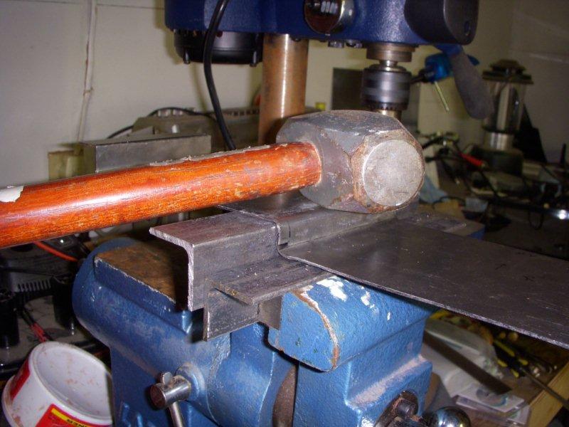
So after the hammer, the heat, and the lube failed to get the rear subframe on, I actually used my brain, and measured all of my ebay solid aluminum subframe bushings. Of course 2 of the 8 had bores that were smaller than the others... I bought some ebay crap and it didn't fit!?! How original. A little time reaming the bushings out, and the subframe went on like it should. Good thing I didn't get out the BIGGER Hammer.
Liberation...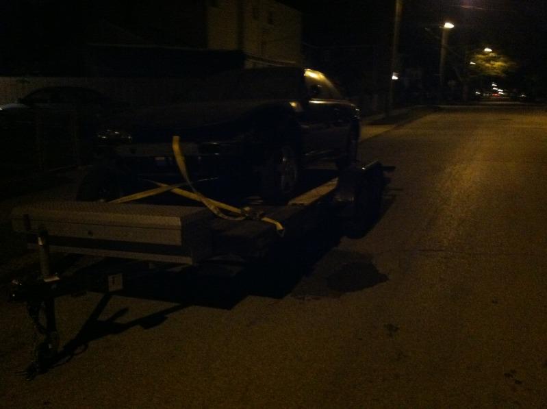
I finally finished patching up the trailer and since I sold my truck when I moved to Manhattan last summer my buddy came over with his truck to help with towing duties. To make a VERY long story short... Two days later I come to understand that ALL rental trucks, and most trucks on the planet have 2" balls, while decent car trailers have 2 5/8" balls. I got everything sorted out, but not until my baby sat on the streets of Elmont (just East of Queens) un-attended for two nights, like a big pile of reprobate thief bait. My karma must be improving, because when I finally got back from a 6 hour drive to borrow my fiancé's aunt's truck, the 240 was still there. And I even made it to my new house in Long Island without getting pulled over for my jankey magnetic tow lights that only worked half the time.
Continuation...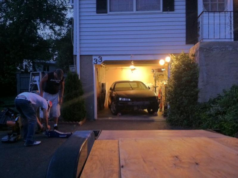
All nestled on her new little home Silvia relaxed for a month or two while I unpacked and got married. Had to sell the trailer to pay the photographer... Hope we don't have move for a while. I've been on a mission to get the fuel and cooling plumbing done for a long time now, so I'm starting with the fuel cell. I'm making a perimeter frame out of 1" square steel. The frame has 2" base plates where it attaches to the rear frame rail, mini versions of the base of a rollcage.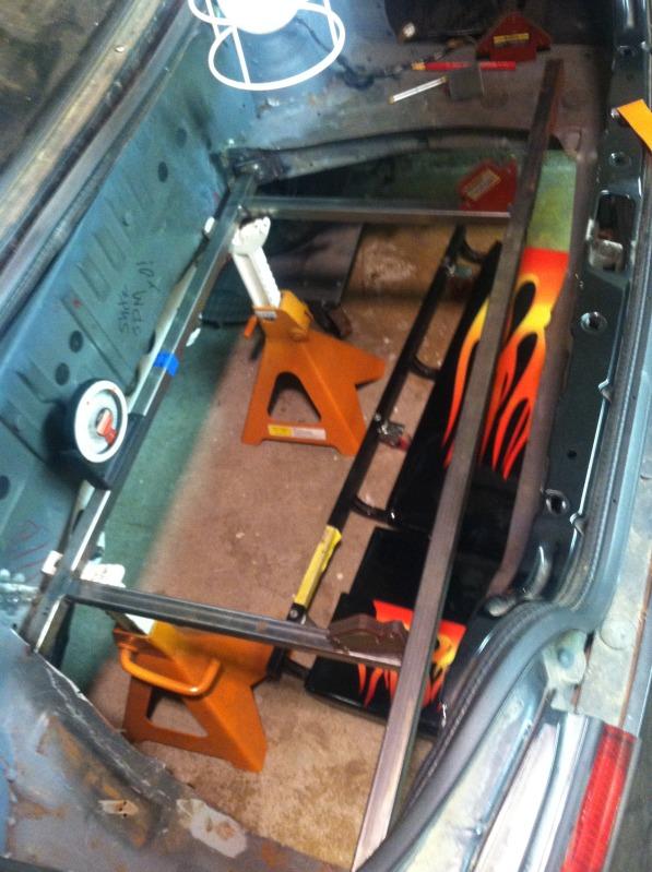
Had to remove this tow strap to weld in the rear cross member. 3.10 Pounds!!! Is this thing made out of Lead?!?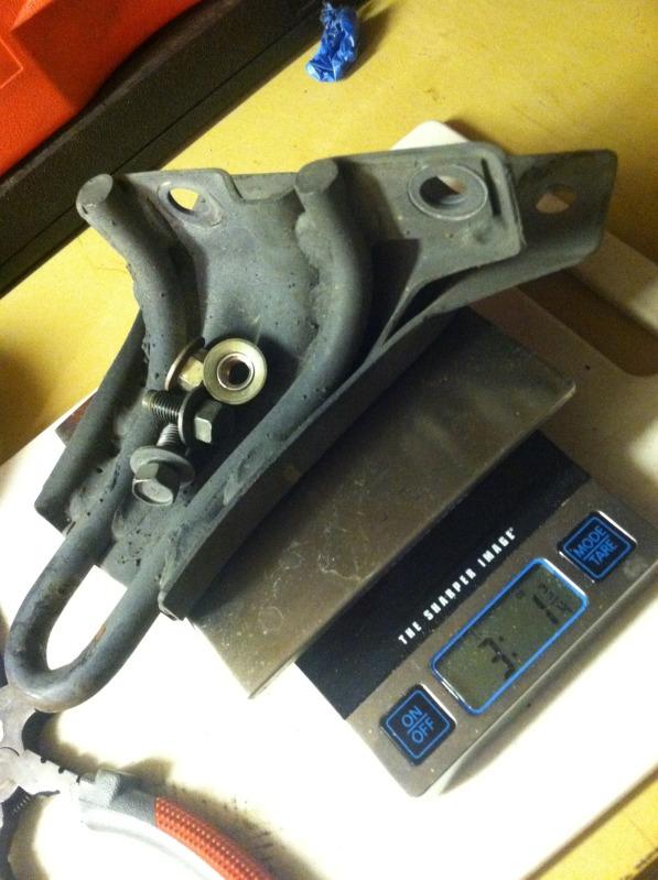
In all honesty I loved that tow strap. It always looked like it was going to scrape on hard launches, and it was the only thing I used to tie the rear of the car down on the trailer. I know I can throw some nylon strap around my rear subframe for the next trailer, but after all this subframe modification/work I really don't want to use the subframe as an anchor point. I was talking about this with my cousin who once upon a time frequented hondatech.com. He asked me about a "Benen", to which I replied, "A what?".
It must be time for sequel to the Fast and the Furious or sumpthin, because my Ricer IQ was FAILIN! If you don't know what a Benen is you gotta do a search! The threads are hilarious (in a "I'm not laughing with you" sorta way). Now in the Benen's defense, it is 0.4in thickness and only 0.8lbs. That's the only nice thing I have to say about Benen. For just a taste:
Help me decide on Tow Hook color. (Pictures Inside) - Club RSX Message Board
Back to seriousness.
You'd think for something as serious as mounting the fuel cell that the rule books we be specific and overbearing... but they are not. There's almost no rules. That probably won't stop a tech inspector from giving you sh*t if you do a lousy job mounting a fuel cell. But feel free to get creative. Just remember: a 22 gallon fuel cell weighs close to 200 pounds full. They say an occupant of a car can survive a crash if the deceleration during the crash is less than 30g. Well at 30g that same fuel cell now weighs 3 tons! So think about that next time you mount a fuel cell by a sorry a$s strap or flange. If you crash harder than 30gs, you probably won't survive, so that big fire ball shouldn't bother you anyway.
I've decided to build a perimeter frame of 1" square tubing to locate the fuel cell laterally and longitudinally. And then to use some sort of strap to locate the cell vertically in both directions. There is one good online article by a circle track magazine that talks about using strap on the bottom of the cell instead of more tube because it flexes more. I don't know if that logic plays out, but strap is lighter, and will allow me to mount the cell lower before something hits. I also referenced a few reputable race shops and most straps seem to be made of 0.050" steel, or 0.063" Aluminum, though I have heard of guys getting crap from tech inspectors (sighting nothing) for using aluminum straps.
I really like this method of attaching the straps, just because it lets you tighten down the straps with a lot of precision.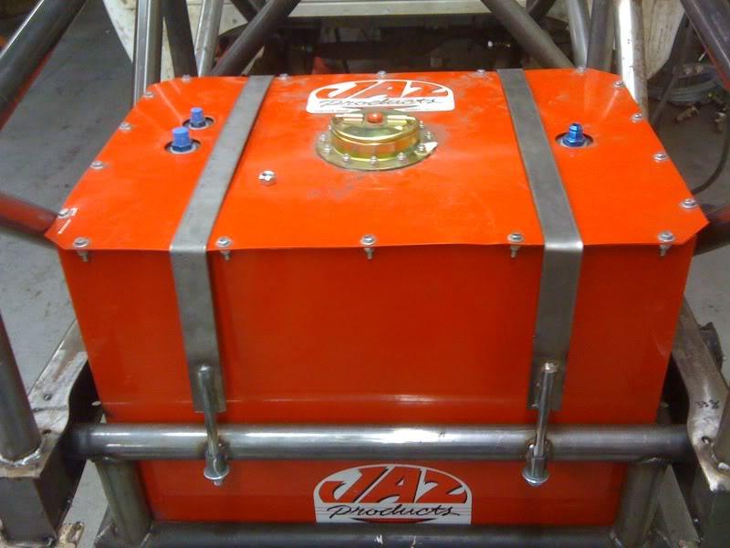
But these straps probably weigh about the same, yet would distribute the load of an impact over a greater area.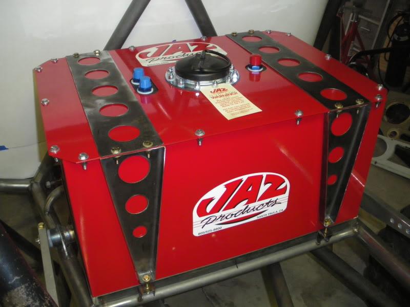
Here's a cool little number from a company that makes mounts for the off-road guys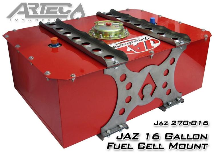
You guys might be getting sick of hearing from me how innovative the off-road guys are, but check this out! Epic, never-starve, fuel pick-ups originally designed by Walbro for snow mobiles! 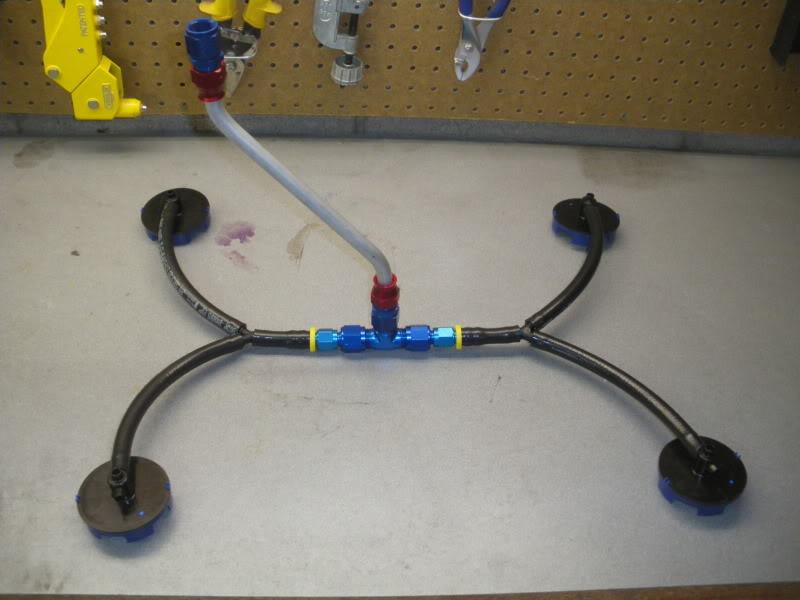
these guys say it better than I could:
Auto Performance Engineering - Walbro fuel pick-ups
And there's also a great thread on pirate4x4 about them.
Here's where I'm at now. I'm having a little bit of trouble deciding how low to mount it though. Most exhausts hang at least an inch below the rear sub frame so that's my reference point (one inch below the rear sub frame). The bottom of the OEM tow hook is about 3 inches higher than that. Because that thing never touched the ground even with NO anti-squat and soft springs, I feel safe going 0.5 to 1.0" below that. Originally I was going to mount the fuel cell higher so that I could have a more effective diffuser, but lately have decided that if I need more rear down force a bigger rear wing is easier to get than the lower CG a lower fuel cell helps achieve.
More coming soon. It's good to be out of Manhattan.
10/11/12
Got inspired by a DIY FLCA and tension rod thread on NRR. So I ordered some 5/8 heims and 14mm high misalignment spacers from the UK.
When the spacers showed up they were upto 0.010" undersized. The summit 5/8 id, 3/4 -16 thread SUM-XMAXL10T Rod ends were dead on at 0.624-0.625" bore. I tried to find some 3/4" to 14mm spacers but couldn't find any.
Should I be concerned about this? The whole point of adding the heims is to get rid of deflection...
Here's a 20 second video of the play.
IMG 1458 - YouTube
the goal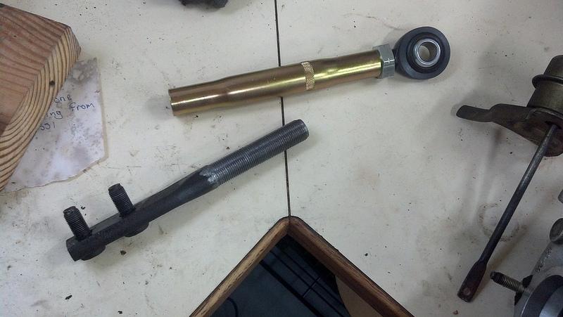
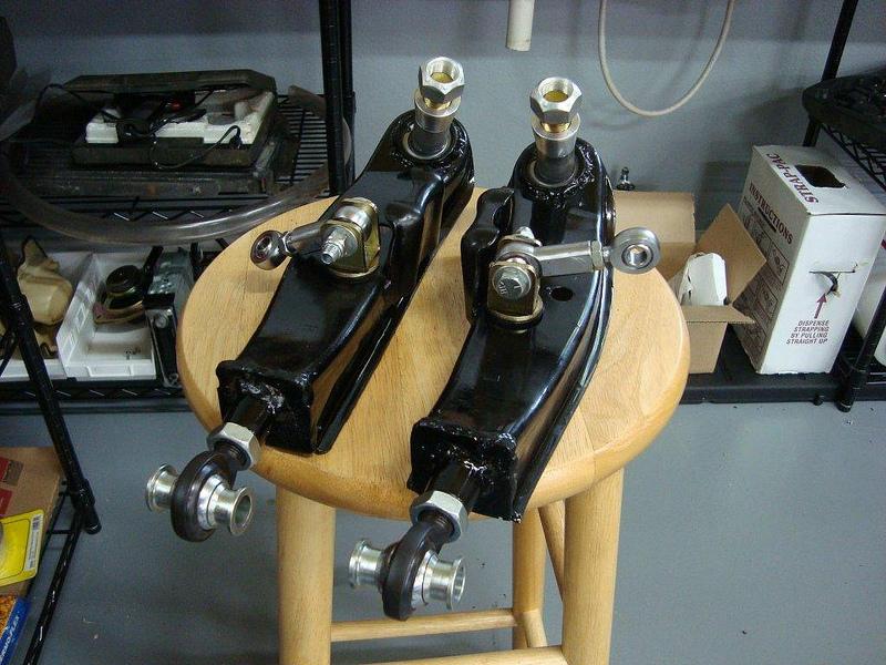
I still need to buy an SAE tap and die set that goes upto 5/8"
I boutgh a cheap metric set at harbor freight and it's horrible. The threads are always loose. I want to pony up for a quality SAE tap and die set. Any reccomendations?
11/23/12
I ordered 5 of the walbro fuel pick-ups: 4x MP-12, and 1x MP-16. None of these have bleed holes, so if the tank ever truely runs dry I might have to take off a fuel line to relieve the vacuum, but APE assured me this was a better idea than providing a bleed hole that might allow air to get sucked into the fuel lines. Originally I intended to put the MP-16 (right angle pass through pick up) in the ATL sump, and send all four of the other pick ups to pass through the last MP-16. But when the pick-ups got here, those 5/16 barb inlet/outlets looked really small. I re-read APEs website,
"A single pickup can flow 40 gal per hour, so they work well with high-performance applications, too."
Auto Performance Engineering - Walbro fuel pick-ups
To put that into perspective a single Bosch 044 flows 53 gal per hour. So is 40 GPH of flow enough?
For Return-Style regulators:
Multiply maximum horsepower by .17 to calculate minimum pump size in "free flow" GPH.
Example: 400 HP x .17 = 68 GPH "free flow"
A single walbro pick-up shouldn't be a restriction until 235 hp (40 GPM/0.17)...
Maybe that's "high-performance" for a snowmobile...
So I'm probably going to need to use some sort of fuel block to run 2 or 3 lines from the pick ups to before the -8 AN OUT on the fuel cell. You really have to be careful with restrictions between fuel pick ups and fuel pump. Both restrictions and high fuel pump mounting placement lead to vapor lock fast.
-12 AN is the standard line used with dry sump set ups. It's damn big and hard to work with. But I read that some Nascar teams run -16 AN to pick up a small amount of horsepower. It makes sense. All automotive oil pumps are crank driven, and pushing oil around under pressure aint easy. For the straigh section of piping under the car (close to 12 feet) I'm planning on using -16 solid stainless line, and then stepping down to -12 for the flexible line.
But if stepping from huge -12 line to even more rediculous -16 is worth some horsepower (and probably better oil pressure) imagine what removing some very sharp 90 degree bends would do. I have to get the oil out of the block and back for both the oil cooler and filter.
Count the number of 90 degree bends the oil has to take inside the block and stock fuel filter to get from the output of the LS1 oil pump to the back main galley...
I count 10!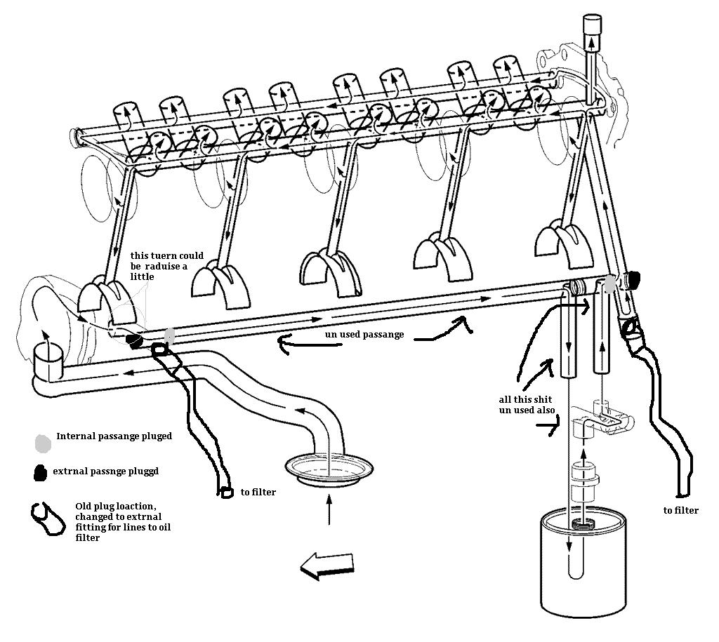
The internal oil galleys of the LS1 are created by drilling out the block. Most of the bores go all the way through the block, and then the access sites are blocked with screw in plugs. Here's a pic of the two bore sites for the main galleys (at the corner of the block). The front bore gets blocked by the timing chain cover, but the threaded galley port (on the driver side of the block) gets a 16mmx1.5 plug that should probaby have a crush washer under it.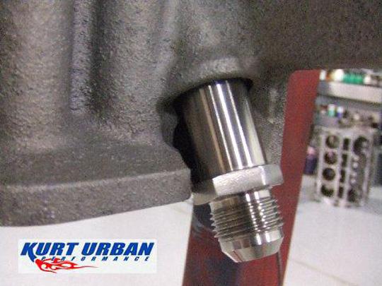
Kurt Urban makes an adapter to tap into the block, here's a pick of it in place of the semi-verticle galley plug at the driver side rear of the block. It has the weird 16mmx1.5mm thread on one end and a -10 AN on the other, custom machined from stainless (but it's $100)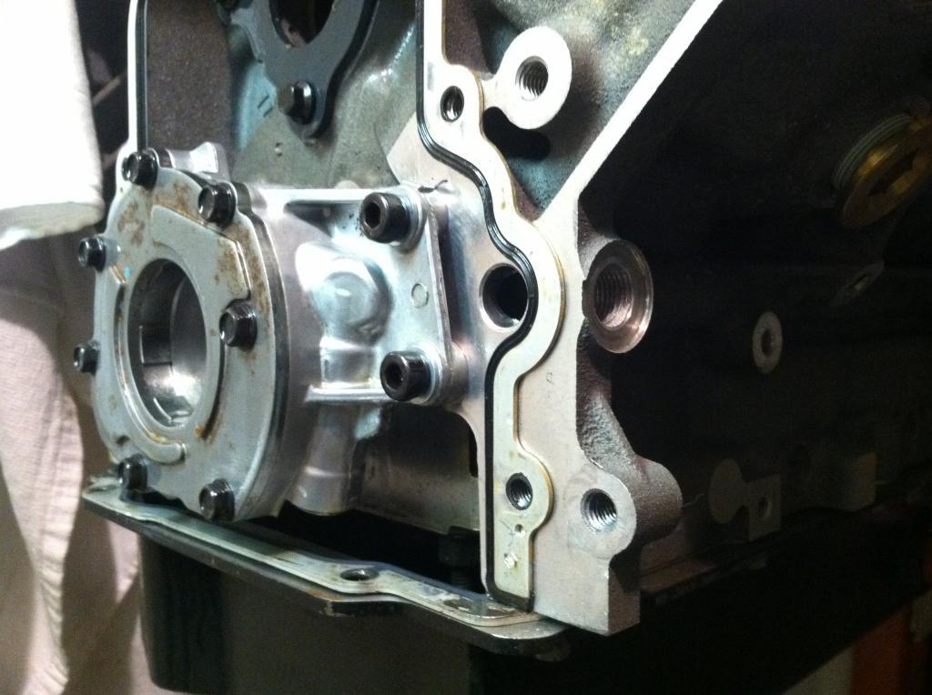
There's also this
Summit Racing Part Number:FRA-460616
Fitting Size 1:-6 AN
Fitting Size 2:16mm x 1.5
(only $3.95)
But here's my problem with both of them.
Internal Oil galley ID: 0.571"mm
Fragola -6 ID: 0.375"
16mmx1.5mm thread minor diameter: 0.577"
EDIT:
I got an email from Todd Brandon (Manager at Kurt Urban) and the bore for their -10 AN adapter is 0.450" all the way through. So that's a minimum wall thickness of (0.577-0.450)/2 = 0.0635" where the threads are.
I really don't want to add another restriction. I consider the internal oil galley diameter to be a minimum.
It's a little scary, but right now I'm planning on drilling the two plug ports in the block for a 1/2" NPT fitting. 1/2" NPT female threads first require drilling a 23/32 bore (0.71875"), and then tapping 0.5337" deep for thread engagement.
In Hot Rod's September 2012 issue they did a comparison of -6 AN fittings(0.375 OD), and the inner bores varied from 0.220" to 0.270". Hopefully this means a -12 AN to 1/2" NPT fitting will have an ID somewhere around 0.595" (finally bigger than the stock oil galley dimensions. Here's such a part from Earls 
I've looked the block over pretty carefully and I think there is plenty of meat for the boring and tapping of the 1/2" NPT. Maybe it would be easier to weld a fitting onto the block, but I worry about messing up any heat treating that was done.
With this external oil routing, I count 10x 90 degree turns that I get to eliminate between the stock LS1 oil pump and the main verticle oil galley at the back of the block! I'll probably introduce 3 or 4 of my own (externally), but all of mine will be WAY more gentle, and that's still a hell of an improvement. Less pressure loss should mean that I can run thinner oil. 0w-20 here I come.
12/4/12
I've been trying to find a source other than Accel for aluminum wiring. Most modern airliners use it at least on their larger generator wires. But the new Airbus uses it all the way down to 22 gauge. Its only 67% as conductive as copper, but since it weighs 1/3 as much it ends up requiring a gauge size two larger for the same resistance compared to copper and still weighs half as much!
"Sigh. It appears that some posting on here never read the old threads on the Airbus "aluminium" wiring, or did not understand what was written.
A380 Not State Of The Art-Due 2 Aluminum Wiring? (by Coelacanth Oct 22 2006 in Civil Aviation)?threadid=3056107&searchid=3062099&s=ElGr eco#ID3062099
This is not the post I was looking for, but it will suffice I think.
ElGreco From France, joined exactly 6 years ago today! , 164 posts, RR: 1
Reply 7, posted Mon Oct 23 2006 12:11:22 your local time (5 years 2 weeks 1 day 12 hours ago) and read 10683 times:
Good afternoon everybody,
I had already answer few times about these questions on aluminium cable technology on A380, but I will do it again with pleasure.
1) few pure aluminium cables are used by Airbus, Boeing, Bombardier,... for years on feeders for power cables to save weight (from A320 for Airbus).
2) A380 is the first plane in the world to use that technology for smaller cables (e.i.: up to #22 contact with #24 cables) but we used aluminium/cooper cable with nickel plated, and not pure aluminium cable (e.i.: each wire is aluminium with 10µ of cooper around and 2µ of nickel deposit).
3) contacts are in copper with nickel and gold plating (as for copper technology) but with longer design to be crimped on the cable and on the insulation cable as well. Furthermore, a ferule is installed in the contact as interface between cable and contact.
4) this technology is based on patent made in 1965, and we are working on that technology from 1967, as many others companies).
5) This technology have been choose in 2002 by Airbus and qualify in 2003. Weight saving is closed from 500kg per A380, it's used on A400M and it will be use as well on A350XWB.
In conclusion don't worry be happy.
El Greco
IIRC El Greco had something to do with making/designing the wiring. Somewhere I think you will find he told us that the Al and Cu are co-extruded and then Ni Plated.
If you want to think that Al with copper, nickel and gold plating is vanilla style Aluminium, well that is fine, but it aint."
Good Nissan read!
Posted by Diggymart on 11/1/21 @ 12:53:02 PM