You must be logged in to rate content!
10 minute(s) of a 390 minute read
3-5-2010
Larry Meaux from PipeMax is going to get back with me today with a picture of how I should build my headers! And last night I used some scrap steel and a dimple die to make the adapter for my throttle pedal. When I drove Courtney's LS2/S14 I saw that he had a simple 0.25" thick aluminum plate that bolted to the car's original bracket and shared one bolt with the GTO throttle pedal. Because I'm not as tall as he is, and my front seat is almost in the back seat I need the pedal ~2.6" spaced out. The brake and clutch peda will need to be spaced out about 3". Having the brake pedal sit about .50" closer to the driver than the throttle pedal will make heel-toe a bit easier I think? I ran out of argon/CO2 before I could finish. But here's where I'm at. It's very light and stiff already, and it's not even gusseted yet.
making it
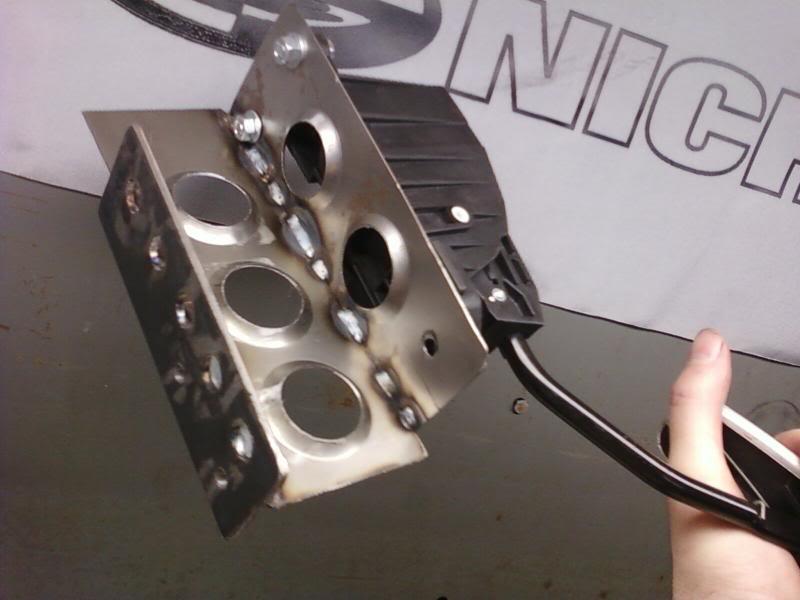
test fit
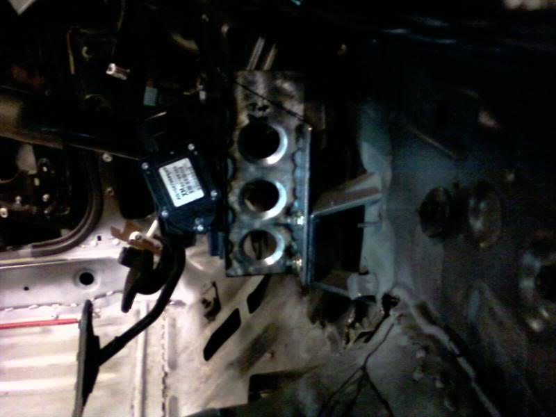
progress, it was hard to get even these tacks done with no shielding gas on such thin gauge steel
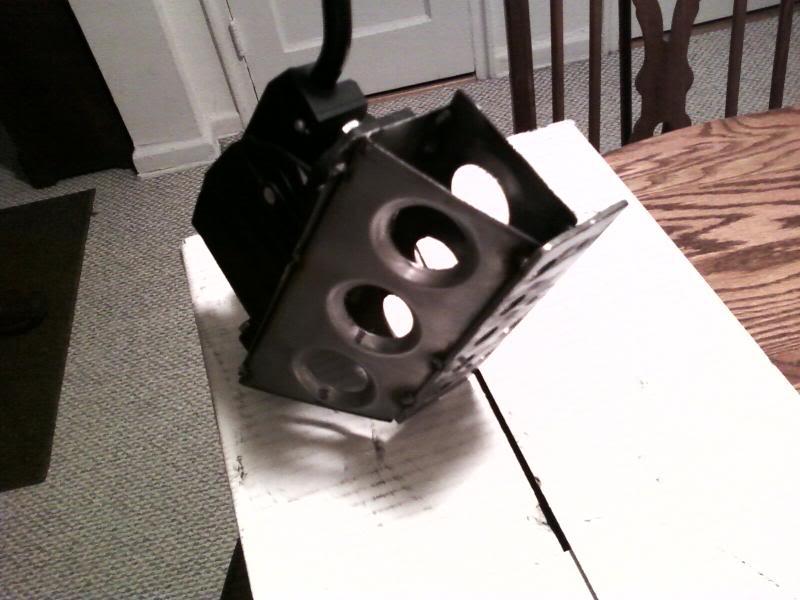
3/9/10
I got a set of new LS7 cnc's heads for <$1000. And in sticking to my budget had to forgo the ti intake valves which run about $800 a setand get stainless which are about 20% heavier.
For reference:
2.205 118.4g (the LS7 intake in SS from REV)
2.180 114.6g (a L92 valve in SS we use from REV)
2.160 106.5g (stock L92 replacement SS from REV)
1.600 92.3g (for reference an SS exhaust valve)
Stock LS7 Ti intake valves are probably in the 95g range as a guess.
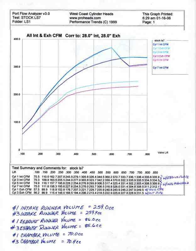
Richard at West Coast Cylinder Heads hooked me up with the most serious valve springs that can still be used with hydraulic rollers, as I plan on using the GMPP Cadillac lifters. It's common knowlege that a lift much over 25% of the valves diameter usually yields very little gain in flow. The LS7 head is no exception.
As you can see from the flow data below. The flow at 25% of the 2.205" intake valve diameter (at a lift of ~.550"), to its max flow which is at .650" lift, the flow only increases 4.4% with the manifold on. And with the manifold off the flow actually decreases at lifts much greater than the magical 25% diameter lift height!
Here's a chart I made regarding piston velocity: @ the LS7s stock 4.000â€Â stroke which I plan on using.
RPM FPM
6000 4000 safe (street)
6300 4200
6500 4333 max (street)
6750 4500
7000 4666 LS7 sits here stock
7200 4800
7500 5000 GENERALLY CONSIDERED SAFE IF ALL FORGED COMPONENTS.
7650 5100 R07 nascar engine
8000 5333
8200 5466 Tosto Drag LSx
"During GM's reliability testing of this engine in its prototype phase, the LS7 was remarked to have been repeated tested to be 8000 rpm capable, although power was not made at that rpm level, due to the restraints of the camshaft's profile and the intake manifold ability to flow required air at that engine speed."
I see no reason a forged LS motor with a 4" stroke shouldn't have a 7500 rpm rev limit. 5000 fpm is considered a safe limit with many engine builders if the bottom end is built entirely of all forged components.
Unlike GM I can use whatever cam I want, so my limiting factor has become my valvetrain. I'm hoping to get around this with some seriously honkin valvesprings and stout push rods. Here are the springs I currently have.
My springs:The valves are REV stainless steel valves part numbers X1131 for the intakes and X1137 for the exhaust. And use 10 deg locks.
seat diameter: 1.450" (My LS7 heads were machined to take BBC size springs)
installed height: 1.855"
seat pressure: 163 lbs
.600" lift: 404 lbs
.650" lift: 426 lbs
.660" lift: 430 lbs (max rec lift)
I havn't measured coil bind yet.
Now the limiting factor is the 1.8:1 LS7 rockers give some lobes too damn much lift. And the other limiting factor is that I fear some of the more popular cam profiles might be too aggressive for such a heavy valve at 7500 rpm.
For example a comp cams LSK 240 duration at .050" lift lobe would have a lift of 0.687" lift with the 1.8:1 rockers! Too much for even my crazy BBC springs! If you want to figure out the lift that a lobe has that's quoted fot 1.7:1 rockers just multiply by 1.0588 to get the new lift with 1.8:1 rockers.
Common LS based comp lobes at 240 duration at .050" lift.
XFI (at 242) 0.648"
XER (at 240) 0.645"
LSK (at 240) 0.687"
Richard at WCCH suggested that I not go too much over 0.630" lift. Looking at the flow data of the heads with the manifold on I can see why. I'd like to keep using stock style lifters to help with the budget. So now the question is which lobe is going to help me get there?
I need something gentle, but of course don't want to sacrifice any ramp speed that I don't have to.
I know there's not a whole bunch of cam engineers following this thread, but I'll keep u guys updated as to what happens and maybe we can all learn something.
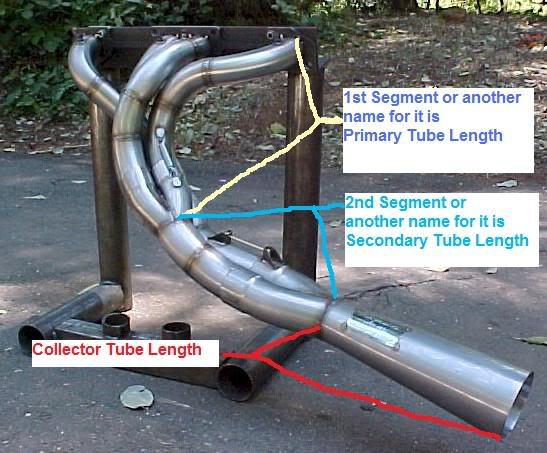
I had been wondering whether or not the primaries ended at the start or end of the first collector.
Larry Meaux of the pipeMax software fame sent me the above photo.
And the following info:
I also have a set of tri-y collectors from nascar surplus that are for 2 OD primaries, and have 2.25 OD secondaries leading to a final merge collector that expands back out to 3.5. I also have a bunch of slip on extensions so that I can get what ever lengths I need, and to make dyno tuning a bit easier if I ever get to it. I'm hoping to use them if they aren't too far off.
__________________________________________________ _______________
What you already have above sounds perfect !!!!
i calculate TRI-Y specs at :
anywhere from :
1st Primary Segment= 1 7/8ths to 2.000" diameter x 13.1" to 14.5" inches long
2nd Segment= 2.000" to 2 1/16ths diameter x 13.1" to 14.5" long
Collector tapers or diverges from 2.811" to 3.816 over 16.0" inches long
so the 2.811 could round-off to 3.000 if need be
and the 3.816 could round-off to 4.000 if need be ?
a merge collector ending at 3.5" diameter looks OK too , its in the ballpark.
___________________________________________
for TRI-Y's, the 1st and segment lengths are critic also they could either be->
13.1 to 14.5" inches long for each of the 1st and 2nd segments which = 26.2 to 29 total length
or they could be 26.2 to 29 long for each of the segments which equals = 52.4 to 58 total lengths
the 13.1 to 14.5 will give you the most HP
the 26.2 to 29 will give you the most peak TQ and bottom end
the only bad thing about TRI-Y's is that to see any real benefitsover a 4-1 Header, the TRI-Y specs must be exact ! otherwise you are better off with 4-1 setup
Larry MeauxMeaux Racing Heads MaxRace Software
http://www.maxracesoftware.com/
3/16/10
I had been wondering whether or not the primaries ended at the start or end of the first collector.
Larry Meaux of the pipeMax software fame sent me the above photo.
And the following info:
I also have a set of tri-y collectors from nascar surplus that are for 2 OD primaries, and have 2.25 OD secondaries leading to a final merge collector that expands back out to 3.5. I also have a bunch of slip on extensions so that I can get what ever lengths I need, and to make dyno tuning a bit easier if I ever get to it. I'm hoping to use them if they aren't too far off.
__________________________________________________ _______________
What you already have above sounds perfect !!!!
i calculate TRI-Y specs at :
anywhere from :
1st Primary Segment= 1 7/8ths to 2.000" diameter x 13.1" to 14.5" inches long
2nd Segment= 2.000" to 2 1/16ths diameter x 13.1" to 14.5" long
Collector tapers or diverges from 2.811" to 3.816 over 16.0" inches long
so the 2.811 could round-off to 3.000 if need be
and the 3.816 could round-off to 4.000 if need be ?
a merge collector ending at 3.5" diameter looks OK too , its in the ballpark.
___________________________________________
for TRI-Y's, the 1st and segment lengths are critic also they could either be->
13.1 to 14.5" inches long for each of the 1st and 2nd segments which = 26.2 to 29 total length
or they could be 26.2 to 29 long for each of the segments which equals = 52.4 to 58 total lengths
the 13.1 to 14.5 will give you the most HP
the 26.2 to 29 will give you the most peak TQ and bottom end
the only bad thing about TRI-Y's is that to see any real benefitsover a 4-1 Header, the TRI-Y specs must be exact ! otherwise you are better off with 4-1 setup
Larry MeauxMeaux Racing Heads MaxRace Software
http://www.maxracesoftware.com/
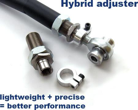
I'm trying to make my own RUCAs but I can't find any male/female double threaded tubing anywhere. Any body have any idea where they can be got? Locking ones like the above SPL would just be gravy. A guy on the nissan road race forums is hooking me up with spacers so that I can use 5/8" heim joints for the 12mm stock RUCA(rear upper control arm) subframe location bolt. So what would be best is a 5/8"-18 inner thread with what ever thread on the outside of the same tube.
These are interesting
Turnbuckle, Female, Steel Race -- Midwest Control Products Corp.
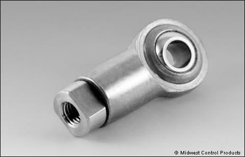
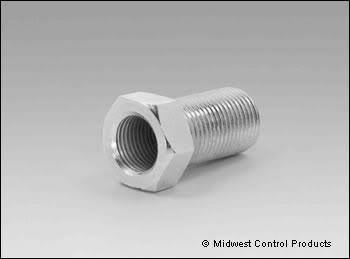
I was all excited when I found these. But then I saw that you can only get them with the same thread direction on the inside and outside. Am I conceptualizing this correctly: you adjust the nut... and nothing happens. The heim would move OUT of the "Thead Bung Adjuster" the same amount that the "Thead Bung Adjuster" would then move INTO the control arm?
Thread Bung Adjuster -- Midwest Control Products Corp.
Good Nissan read!
Posted by Diggymart on 11/1/21 @ 12:53:02 PM