You must be logged in to rate content!
7 minute(s) of a 377 minute read
2-27-2012
I am not only charge cooling it but I am putting on a bigger crank pulley (6.37" - original is 5.465") (this will help with low rev water flow) and believe it or not a bigger blower pulley (3.4" from a 3.3"), now that might sound odd as you would normally put on a smaller blower pulley to spin the blower faster. In this case the CP is that much bigger that it would be spinning the blower beyond its comfort zone. With the new setup the blower is spinning approx 2000rpm faster than before (was 14500rpm, now 16500rpm @ 8800 engine rpm). The actuall PSI seen in the manifold wont be that much greater as there will be a pressure drop in the intercooler, not as great as an air to air I/C but still an amount.
I also never got around to finishing my new manifold to go between the throttle body and charger, this will be done and I will be fitting the 72mm throttle body to it along with a new air filter I should see some serious gains. It was 288HP at the hubs last time on the dyno - I am going to wet finger in the air and say I am hoping for 340-350hp at the hubs, if it does come in at that I will be very happy. To get a BHP figure at the crank I add 10% for drivetrain losses.
I cant admit to it being all my idea as others have put an intercooler in the same position but none with the same cooler as mine as it is a bespoke item.
I never did see the twin rad setup, maybe post it up in your build diary for us to see, so others might have an idea of how to do it.
3-8-2012
I decided to ditch my Acetal thermal gasket as I was concerned about heatsoak when shutting down a hot engine after being on track so I looked deeper into plastics and their respective thermal properties and have decided to use Polytetraflouroethylene (PTFE) as it has amzing heat resistant properties, its good from -260 to +260 Deg C (-436degF to + 500degF) and is readily available in sheet form of many thicknesses.
I am going to stick with the Acetal between the charger/aftercooler and the aftercooler/manifold.
The PTFE is also much easier to work with if you have limited resources, again I produced the part with a pillar drill, a 4mm drill for chain drilling, a 12mm drill for the top of the ports and then also for smoothing the ports and finally a 9mm drill for the bolt holes. Be warned if using a hand drill the material will pull you into it as it is quite soft material.
Unfortunately the only photo I took so far is with the OEM gasket on it being used as a template.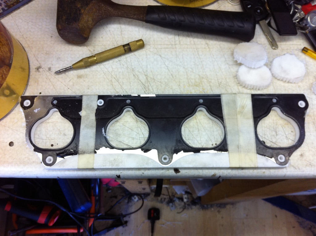
And this came through the post the other day (K24 crank pulley, 6.37"):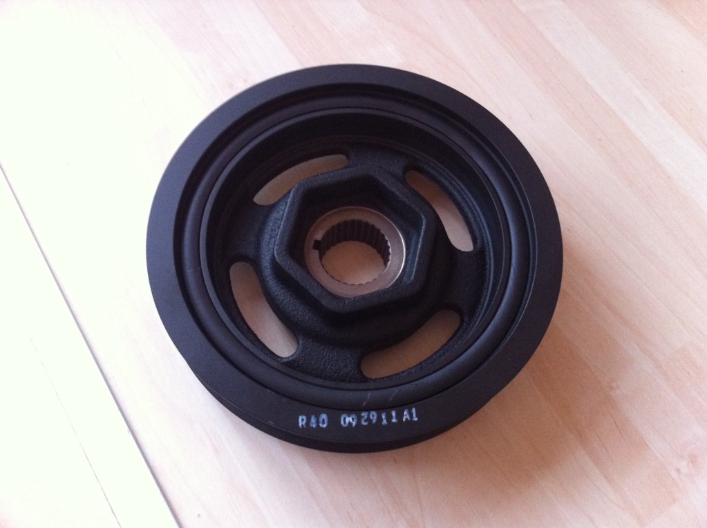
I need to start extracting the digit or summer will be here before I know it.
3-14-2012
Some more done over the weekend:
1) Crank Pulley replaced.
Before I put the new pulley on I decided to weigh it, more out of curiosity thatn anything else and the results were really quite surprising. Below is a photo of the two next to one another and then them seperately on the scales.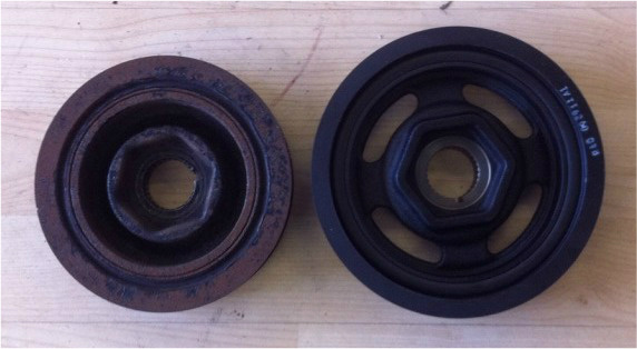
K20 original:
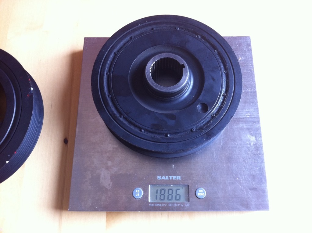
K24 6.37":
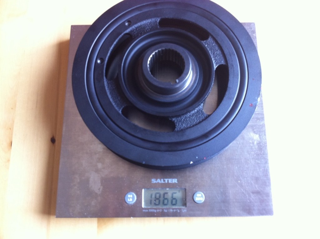
Yes thats right, 20g's lighter and considerably bigger.
2) Snout Clamp
I offered up a paper template of the latest and simplest design, pretty close, just a couple of mm adjustment and we are there.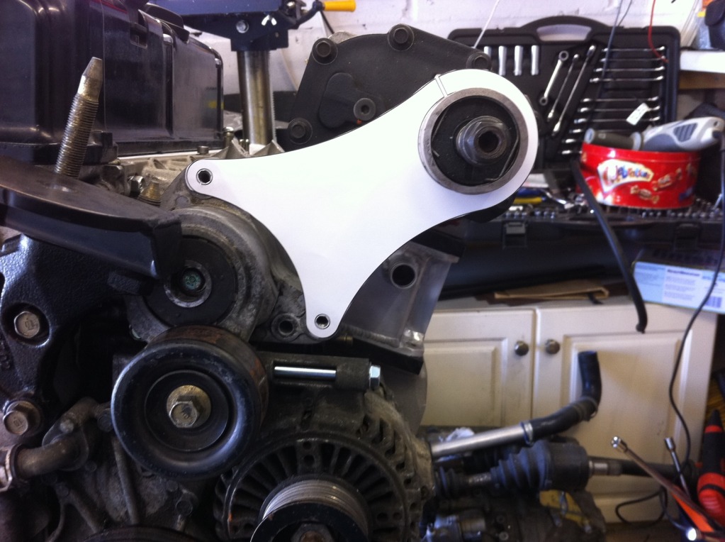
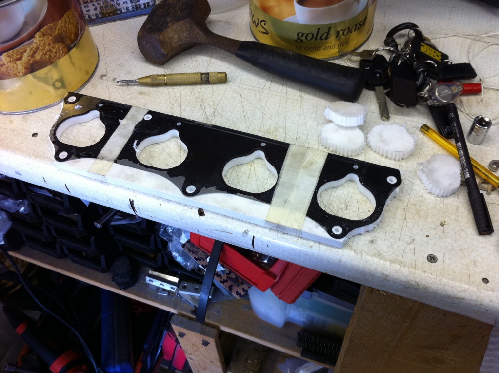
3) Thermal Gasket
I got a better photo of the new PTFE Thermal Gasket when I pulled the charger off the motor again.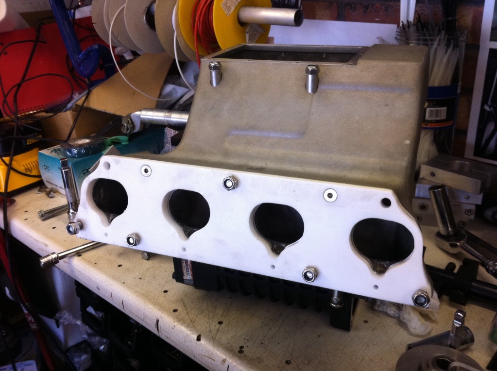
3-24-2012
Well theres not much been happening actually on the car but theres been some more research and design work going on.
I now have a new design for the belt routing which incorporates the latest revision of the snout clamp (version No.11).
I am going to be using the OEM grooved idler pulley that is used on the EP3 Civic and will be using another smooth tensioner, the same as in use on the auto tensioner. I have drawn up 2D pulley layouts as was suffering with what appeared to be belt stretch and wanted to know how effective the auto tensioner was in its current configuration compared to the OEM setup. I drew two setups, measuring the theoretical belt length, one with the tensioner completely off and one with it as it would be without a belt (fully on). So my current setup on had a difference of 21mm in belt length, hence it being a b1tch to get on and n ot able to keep the tension very well, compared to the OEM setup that had 60mm difference in belt length. As an added bonus it has increased the amount of wrap on the supercharger pulley by a considerable amount, very happy.
I have the plate and billet rod sat here waiting to be machined and should be able to get the turning done in the week and the mill work next week. Bring on the light nights so I can work on the car.
For those that are interested I did a few renders of what the new setup will look like:
Heres what the current setup route would be, the red arrow shows how the tension goes on to the belt: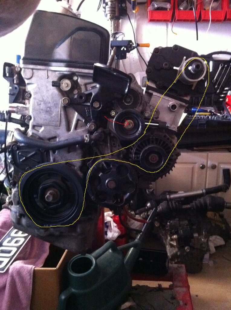
Heres the new setup: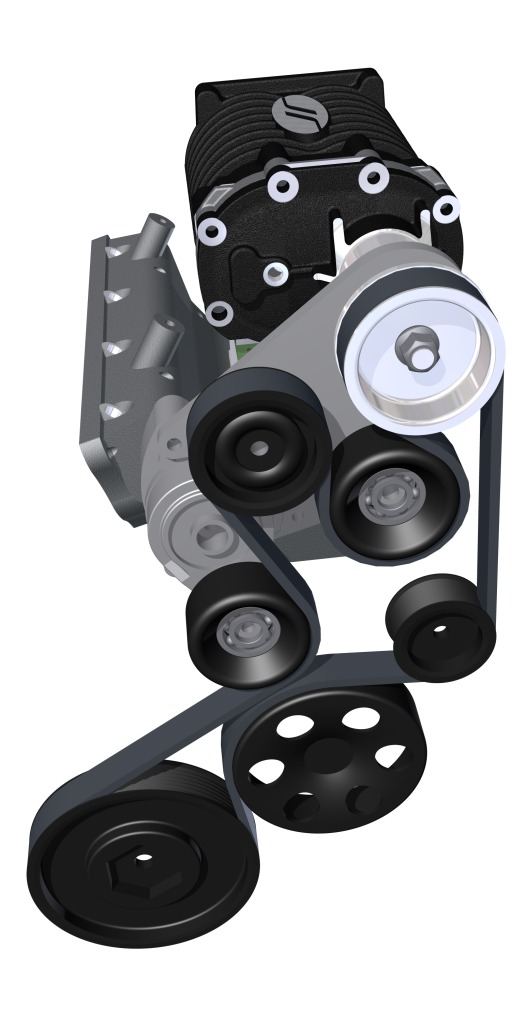
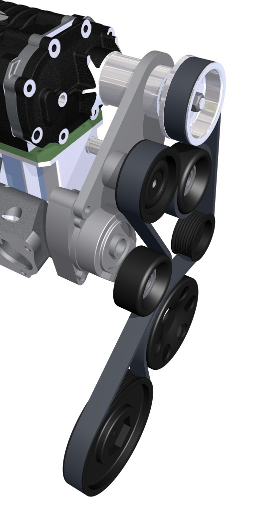
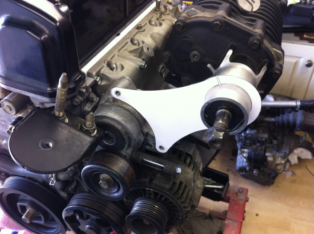
One showing the new snout clamp/pulley mount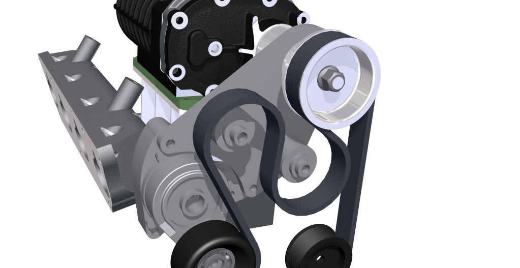
My mate Jim Bright turned these for me the other day: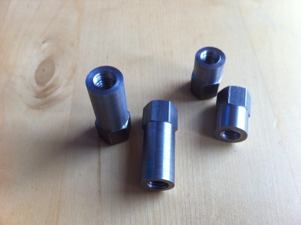
They are to go on the end of these: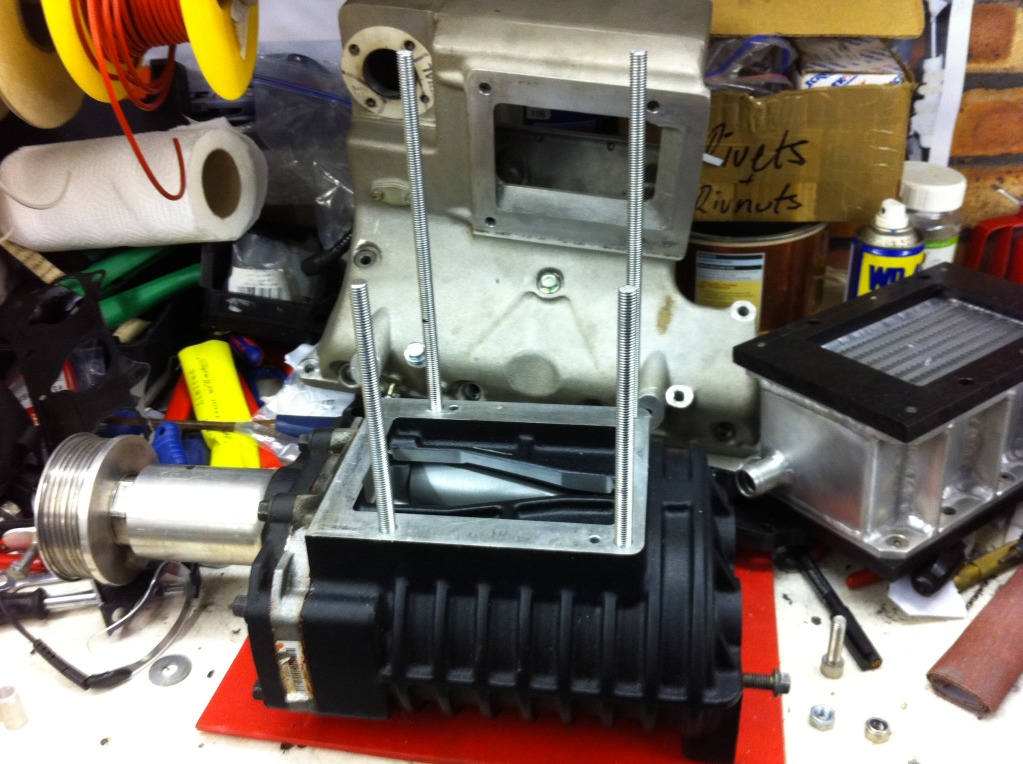
To replace the ones you can see in this shot and the two that sit inside the intake manifold: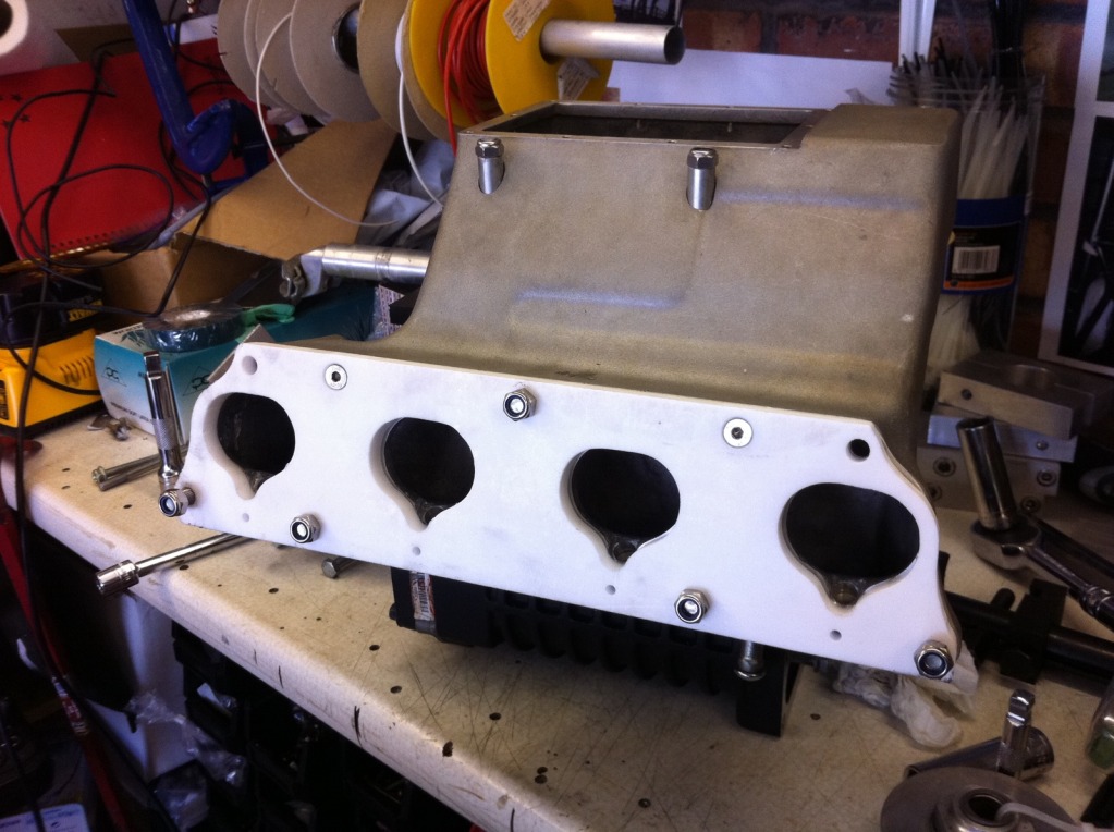

Wow this is amazing build!
Posted by Diggymart on 2/3/20 @ 4:10:14 AM