You must be logged in to rate content!
7 minute(s) of a 97 minute read
3-13-2015
Stopped posting every last thing, and all of a sudden it's six months later!
Engine is in, fuel system mostly done, lots of detail work done, much to go. Will post many photos tonight, using this entry as a bump.
3-14-2015
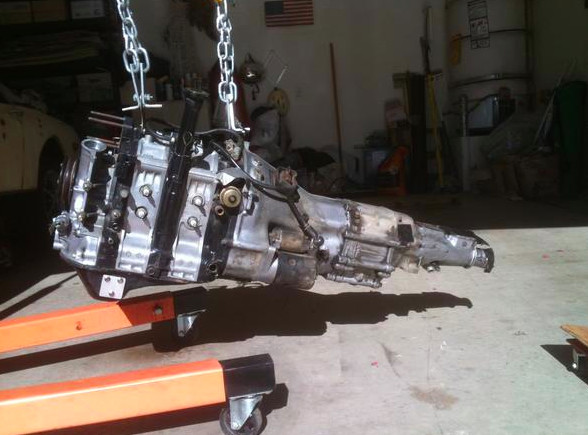
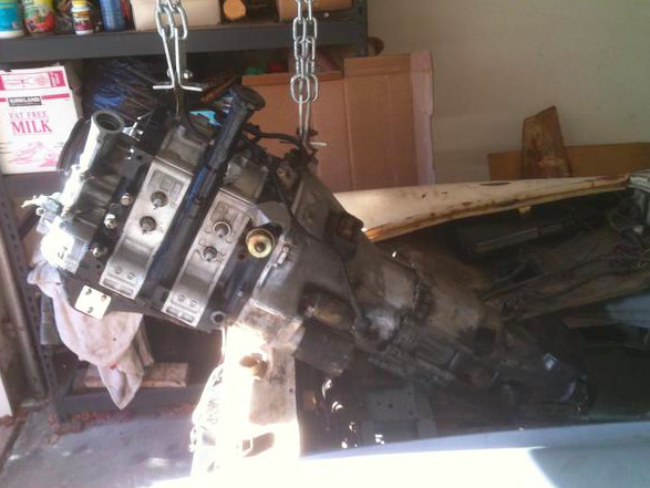
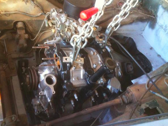
The "for real" engine going in, just like a 1275. Putting the engine and transmission together first works just fine, as long as you have a way to steeply tilt the assembly on the way in. Blocking off the left side oil pan sensor is a necessity, the assembly will not clear the frame rails otherwise. Building a smaller oil pan is an alternative, but the stock pan will just fit if you notch the right side frame rail for the drain plug (or move the drain plug). The bellhousing and transmission case is generally bigger around than the factory MG piece, but the transmission tunnel will accommodate all of it, as long as the heater/battery tray is trimmed back.
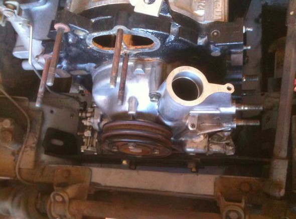
The front engine mounts (roughly in the location of the factory engine mounts) are actually solidly mounted, while the rear mount will incorporate a small strip of rubber between the factory frame crossmember and the transmission, to give just a bit of flex to the unit. Vibration and harmonics on a rotary, due to the solid mount, should not be a problem. We will find out.
If anyone is interested in more detail on the actual mounts, which are backed with fitted pieces of plate steel, I can post more detail on those.
More tomorrow.
OK, heater next, why not?
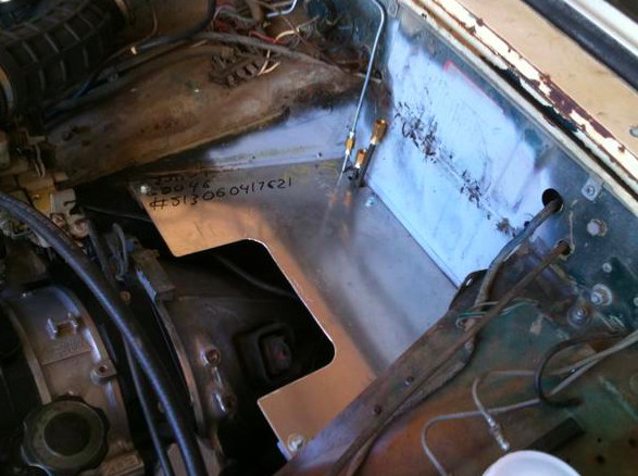
It will have a heater, but the battery will move to the back of the car. Rotaries require big, heavy duty batteries, which would not easily fit in the standard location anyway. So the heater box will be moved slightly rearward, and the battery will go somewhere in the back half of the car. Per the photo, you can see the big "notched" panel, made from aluminum. The heater will sit on that panel, just aft of the notch. I am looking for an early heater box, or I will modify the later one by removing the fan from it. As you move the heater box aft, the top shelf of the footwell rises, so the factory fan won't fit. I will probably use a fan from another car, an aftermarket piece used to ventilate the driver's helmet in race cars. A bit more compact.
The aluminum panel will have holes cut in it for the output from the heater box. The center hole will empty down into the transmission tunnel, while the holes on either end will duct to the defroster and footwell ducts. That way the heater and fan can be operated even when the defroster and footwell ducts are closed. The reason is that in this application, the factory Mazda oil cooler that fits between the oil filter and the engine block (on the top left rear of the engine) is going to be used. For a performance application, a traditional style external oil cooler would be used (similar to the factory Midget piece, only larger). For a street application, the factory oil-to-water intercooler will be used, and an installed and operating heater core is integral to the system. This is similar to the set-up used on some early RX7s. The coolant output from the engine that goes to the heater core will be routed through the intercooler first, then to the heater core, and back to the radiator. Rotaries generate so much heat that dissipating it, in part, through the heater core, is an important part of the arrangement here. I think it is an elegant solution to a difficult packaging situation, where the entirety of the front of the car is really needed for the larger radiator.
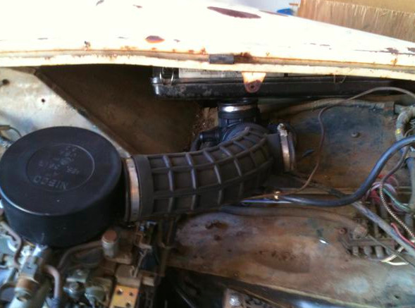
The next photo shows the duct that will fit between the air cleaner in the gap on the right side (between the footwell roof underneath and the fender overhead), and the carburetor inlet. This is a junkyard find from a Daewoo. Yeah, lots of those to choose from... The smaller outlet pointing to the right side of the photo will feed the heater fan, so the air running through the heater box is filtered and not drawn just blindly from the open engine room. The fuse box will likely need to be relocated.
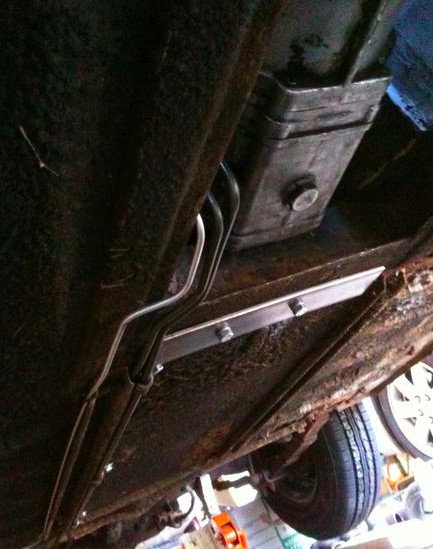
The third photo shows the transmission mount reinforcement underneath, and the three lines coming forward from the back of the car, which make their way through the aluminum panel overhead. The largest, 5/16ths, is the fuel feed. A Facet pump has been substituted for the factory MG fuel pump in the factory location, as it is well matched for a street rotary. The middle line, 1/4 in diameter is the fuel overflow/return line, which feeds back into the fuel tank. Back in the right hand side of the trunk is a small metal canister that this line ultimately goes to, and it has been bypassed so the overflow return line flows straight into the fuel tank (right by the fuel filler tube on the top right hand side of the tank). The small 3/16ths line is the rear brake line, which snakes through the transmission and driveshaft tunnel in the factory application. In this case, we take it under the car, as the Mazda transmission is a tight fit. The lines follow either side of the right side seat support rail, so that the left side of the undercarriage can be dedicated to the hot running exhaust system.
The Mazda uses a large diameter 5/16ths fuel feed, and rather than have the fuel pump slow down like in a Midget factory application, when fuel needs are light, the Mazda fully flows and recycles the extra fuel back to the fuel tank through a 1/4 inch line. I believe this is so that the fuel, at idle, will not flow more slowly, soak up engine room heat, and make the car malfunction. We are duplicating that set-up in this car. Currently, the three lines are routed through the aluminum panel, to junctions above the panel, where the battery would be in a stock Midget application. I am looking at using bulkhead fittings instead, so the lines can be fitted with ends on either side of the aluminum panel. I would like the junctions to be mounted on a small piece that is independent of the larger panel, so that removing the large panel is an easy task. The panel, held on by four bolts, needs to be removed for engine removal and installation (which can sometimes be a semi-regular event with rotaries). The "notch" in the panel allows clearance for the top-mounted clutch slave cylinder (Halleluiah!), and also just enough room to reach underneath to help in installing and removing the four bolts.
More tomorrow.