You must be logged in to rate content!
12 minute(s) of a 668 minute read
3-1-2012
Thanks for checking guys, I forgot about the upper shock mounting tabs, they were a pain to get to match since I was working on a up hill, horizontal and vertical fit. They took a while, but it was worth it.
The crossmember, the torchmate did great on the sides of the crossmember, but I can't describe the patience of shaping the tops and bottoms. I was extemely set on not using any heat to shape those. By using the heat, sooner or later I'd use a hammer to pound things to fit, it just wasn't gonna happen, I didn't want and hammer marks when done.
Now the frame sections. When I started this thread, I figured everyone assumed it would be some overlapping patches to repair the bad spots. I recall the responce once I posted the finished welding and grinding. I knew with the responces there would be new interest in welding.
It's been 8 months now we've been going at it, and it's been an absolute pleasure.
Quick review so far. Hopefully these things I post next have stuck with everybody so far.
Squarebore and spreadbore carbs. By the way, when I showed the spreadbore, it was of a Quadrajet carb. Holley also makes spreadbore carbs.
Vacuum operated secondary carbs. They open by the demand of the engine. They can be adapted by the springs to meet the needs of different engines and applications.
If we force the secondaries open on a vacuum operated carb we get a hesitation. The secondaries do not have an accelerator pump for the immediate opening of the secondaries.
Port vacuum and manifold vacuum. The port vacuum is above the throttle plates, there is virtually no vacuum at idle since there isn't much air flow yet. Once you open the throttle plates, the air flow create a vacuum. To operate the secondaries, this is the perfect situation. The vacuum canister gets it supply by bolting to the side of the carb. But look closely, you'll usually find a hose nipple sticking out the front or side of a carb that is located about midway up the carb. This is usaually a port vacuum hook up.
Manifold vacuum, great vacuum at idle. The engine is running, the cylinders are sucking air but the throttle plates are almost fully closed. These hose nipples are usually right at the base plate of the carb.
We have distributor advance, transmission vacuum modualtors, brake boosters, emission control, even shaker hood shops, ect. All these work off the vacuum. There are parts inside and outside of carbs that deal with vacuum also, understanding these parts and their operation will be a great benefit someday if you build a hot rod or do any modifications.
The accelerator pump has come up a few times, it's time to go there.
First thing I have to say about the Holley accelerator pump system, even for those who have messed with Holleys, there is a boat load of settings you may not be familiar with. And nobody likes a hesitation, an inproperly set accelerator pump is usaually the problem. Oh boy, where to start......
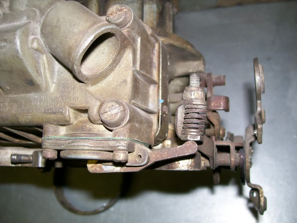
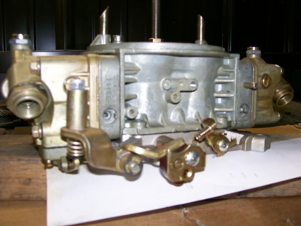
First let's look close up at the carb at idle, no pushing of the acceleratorpump yet. In the picture below, there are at least 3 changes or settings possible, yes, this might take a while.

I won't write much here so the pics stay close together. This is the carb in full open position. Notice the changes from above.
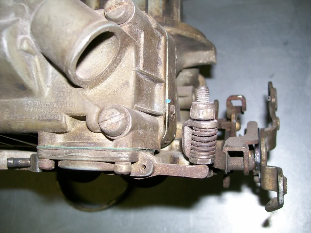
Ok, first, the throttle shaft rotated. You can see the arm that touches the throttle shaft has raised, which in turn. due to a pivot point, is gonna push downward on the lever that is at a 90 degree angle to it. Then the lever at the 90 degree angle has it's pivot, which in turn ends up pushing upwards into a rubber diaphram that has a pool of gasoline ready to be pushed into the carb.
Going back the the lever touching the throttle shaft. Obviously we have an eccentric, something than is now round but has a high spot built into it. Once rotated, it rose upward and pushed the lever upwards.
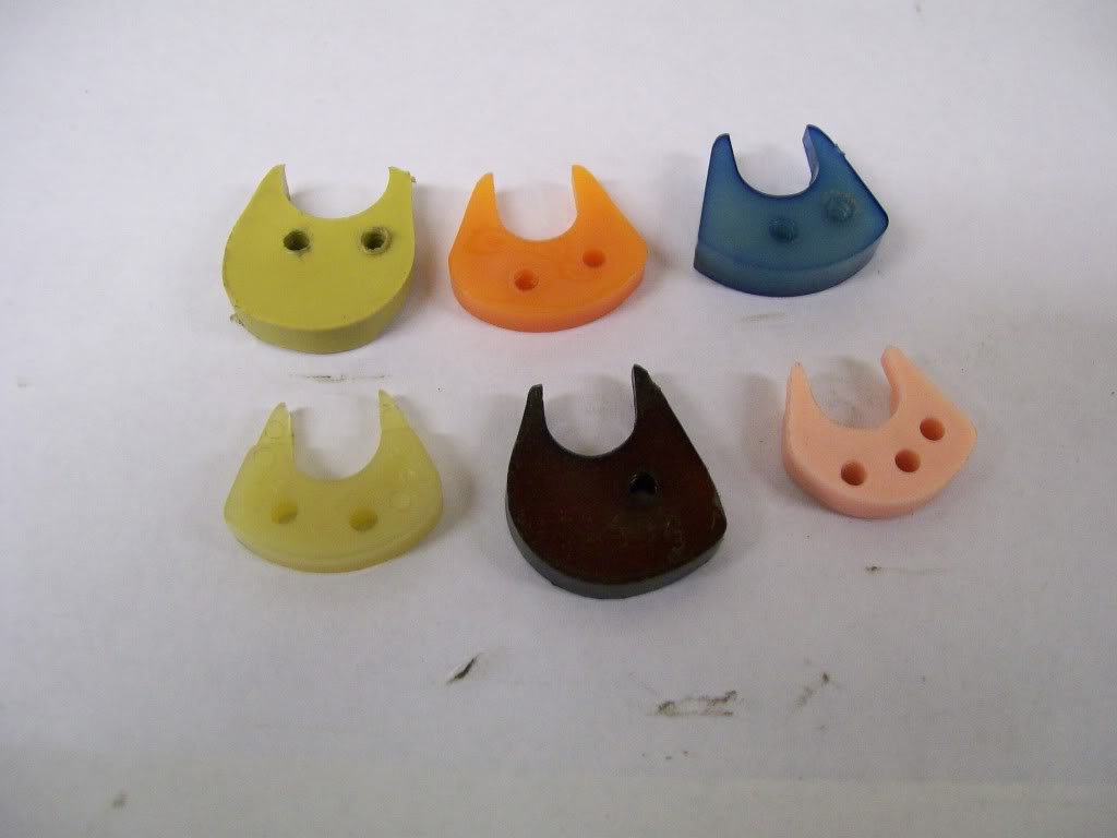
This is the first place for adjustment, most don't even know about this adjustment. There is a plastic piece that is held in place by a screw. Go back to previous pics, in post number "852" you'll see the screw and how the first lever is being pushed upward by the plastic cam. You'll also see a hole marked "2". You will have multiple choices to change these plastic "cams" and at the same time, use different holes also. Oh my head hurts just thinking of the possibilities.
Once again, Holley has a kit. You'll notice different cuts on these cams. They all change how much, and at what rate the fuel will be shot into the intake. You'll also notice the 2 holes in most of them, these add to the variables when setting up your carb. Depending on which hole in the cam, and which of the two holes you use on the throttle shaft, wow, the adjustablility is endless.
3-2-2012
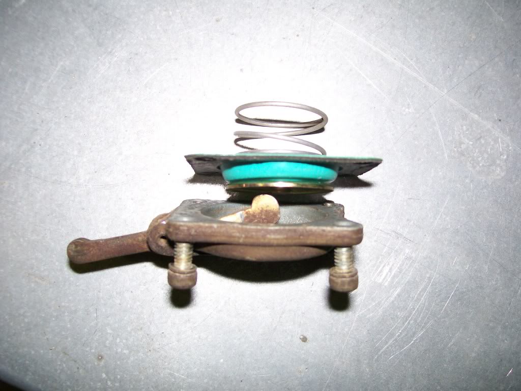
Let's take a look at the heart of the accelerator pump. In this next picture I've got the pump itself apart. in some way it's similar to the vacuum secondary rubber diaphram, it just doesn't work off a vacuum supply. This one works off a mechanical force coming through the lever.
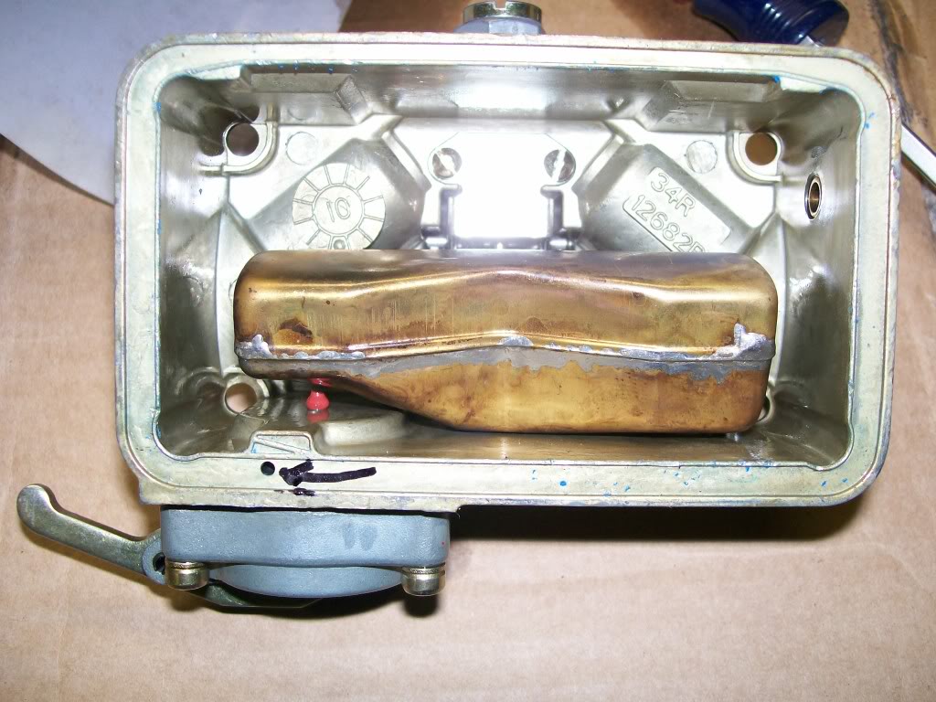
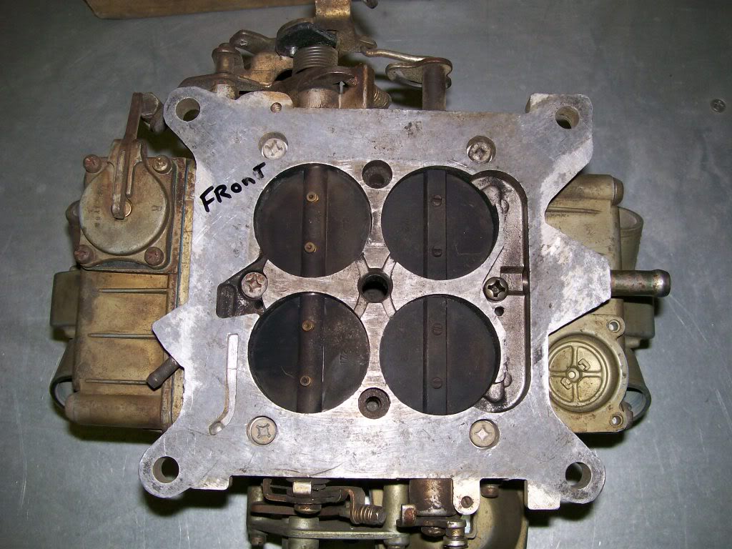
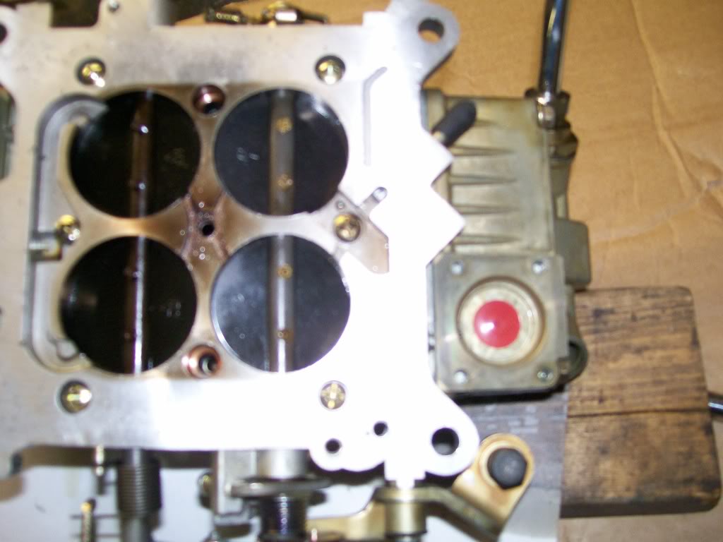
Here is the carb upside down. Near where I wrote "front" is the accelerator pump. Looking to the other end you can see where Holley does build the casting for an accelerator pump on the other float bowl. If this was a mechanical secondary carb, we would see an accelerator pump there also.
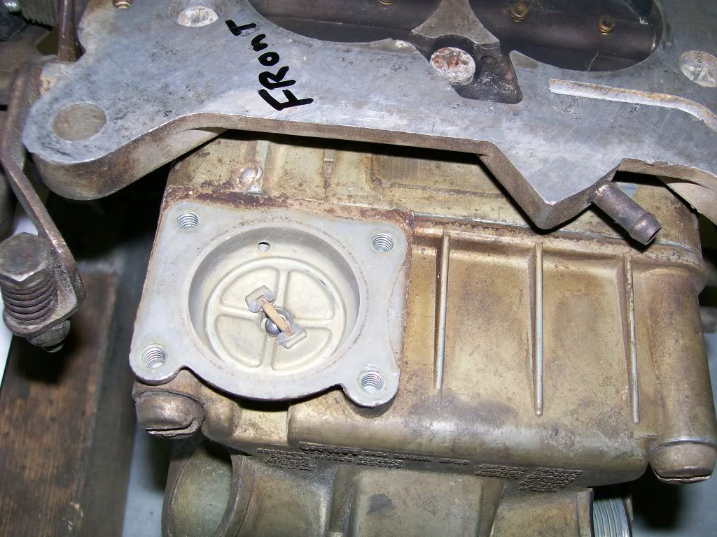
Since we are under the carb right now, it is a good time to verify the "manifold vacuum hose outlets. The small and the large hose outlets are directly a part of the base plate, drawing their vacuum from under the throttle plates.
With the pump removed we can see the inlet and the outlet ports. The inlet is the one with the steel ball being held in place. Right now with the carb upside down, the ball is resting against the hole where the fuel from the float bowl would drain into the pump area. If the carb was right side up, the ball would be away from the hole and fuel can drain into the pump area.
The purpose of this ball is to act as a one way check valve. Fuel drains down past it, but once the accelerator pump is activated, the pressure forces the ball upwards so the fuel cannot go back to the float bowl.
Since the fuel has to go somewhere it is forced out the small hole you see on the outer parimeter of the pump casting.
3-3-2012
Hi Scooter402, This is a somewhat older one. I'm gonna date myseilf here, I bought it new back around 1978.

This aftenoon I'm gonna replace the power valve in my newer carb. I'm gonna get some pictures of the accelerator pump on it for a comparison of the stock one vs the 50cc unit. Mainly to show one more choice in dialing in a Holley carb.
Without getting too far ahead of this teaching. I notice you mentioned the steel ball in the picture. Are you refering to the alternative check valve that Holley used that was a rubber design? or are you refering to the steel ball they use just before the squirter?
And yes, there will be a study on the squirters coming up soon also.
I do appreciate any comments along this teaching, I may assume everyone knows about certain parts but may not. If you're anything like me, if I get stopped by not know how something works, I'm a mess the rest of the way.
If someone doesn't want to publically write something, I do answer PM's also.
I'm still on the accelerator pump learning and we're gonna be here for a couple more posts.
Today I want to tap into the idea of figuring how something works and not just to change the part.
If I spell this right, I'm talking about being a diagnostition, vs being a partschanger.
Had I wanted everyone to be a parts changer, I'd have shown a parts illustration and not tried to break down the what fors and whys.
I get the feeling I have a group who desires to be diagnostitions, people who understand not only where the part goes, but why it is there and perhaps why it was made the way it is instead of a different way.
Ok, that's where I'm heading with this next post. I'm gonna show yet another choice that Holley has in the way of adjusting the system to fit your needs.
I've shown a standard sized fuel pump diaphram earlier. This next picture has the standard size and a 50cc high volume replacement.
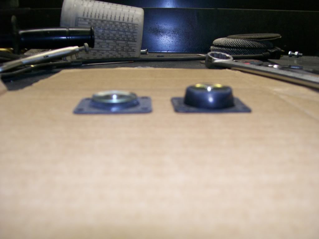
I worked on my high performance carb today. While I had it off I figured I'd take a couple pics for comparison, and learning.
Along with the much larger rubber diaphram, in the kit you get a larger canister, spring, and the pivoting linkage that rides on the plastic cam on the throttle shaft.
Obviously there is quite a difference, that 50cc one is gonna push alot of fuel. Now considering the fact that gas in the carb is a liguid, and liguid is not compressable.
Anyone know where I'm heading yet?
Imagine, we sit with the engine running at the start line at a drag race, the tree flashes down to green. Once it turns green, our foot is gonna go to the floor. All the fuel that goes into the engine is gonna be drawn by vacuum except the shot of fuel by the accelerator pump.
The outlets that the fuels comes out of are only 30 to 40 thousands of an inch in diameter. Now especially with the high volume rubber diaphram, were gonna try to force fuel to the outlets faster than the fuel can get through the outlets.
We have to have a way to absorb the force going from the cam to the rubber diaphram or we could burst the diaphram.
I have to figure the rubber diaphram will expand under pressure, but at what point would it burst. There is another item that absorbs some of this sudden pressure.
Any idea how some of the action is absorbed, and then dispersed within a couple seconds later?
It is looking at the parts and figuring why, that I enjoy mechanics. My hat goes off to the many engineers that figure this stuff from scratch.
Ok, I get the impression carbs are the focus at the moment.
Scooter402 brought up a good point. The steel ball check valve I pictured is old school, although I'm not sure what year the went to a rubber check valve.
The rubber one basically snaps into place. It has just enough give and flex that when the accelerator pump is pushed back into place by the spring, the negative pressure pulls fuel past this rubber valve.
A picture of it.
This picture really focused good. Now we're inside the float bowl. Look closely, we'll cover the insides later but for now we can see the red rubber valve sticking up. In the same picture I put an arrow showing a hole. This is where the accelerator pump fuel passes through on it's way to the main center section of the carb.