You must be logged in to rate content!
12 minute(s) of a 668 minute read
5-13-2014
I didn't notice til you mentioned it, 100 pages, who'd have thought. I think we're well over 1000 pictures also.
A couple of months ago I did go back over the first 50 pages, it certainly has been alot of different paths covered and great communication along the way.
Jeff88, always there with words of encouragement.
Gojeep, sometimes, (I know you've probably been through this before), we build in one direction only to change our minds later. This is the case with the beads pressed into the side panels of the floor tunnel. I didn't plan on any stainless work til after I did the bead work. Then I pulled out the doorpanels and realized it will more match the door panels with the bead pressed in. Everything matched all the better.
We're gonna switch gears today, paint work. So far I've done a bunch of paint but it's all been flat black on frames and axles, about the easiest stuff to spray.
I'm moving to the inner front fender panels. They are located and at an angle that will reflect the silvers and chrome nicely, so I plan on optimizing their usage.
Here is the fit.
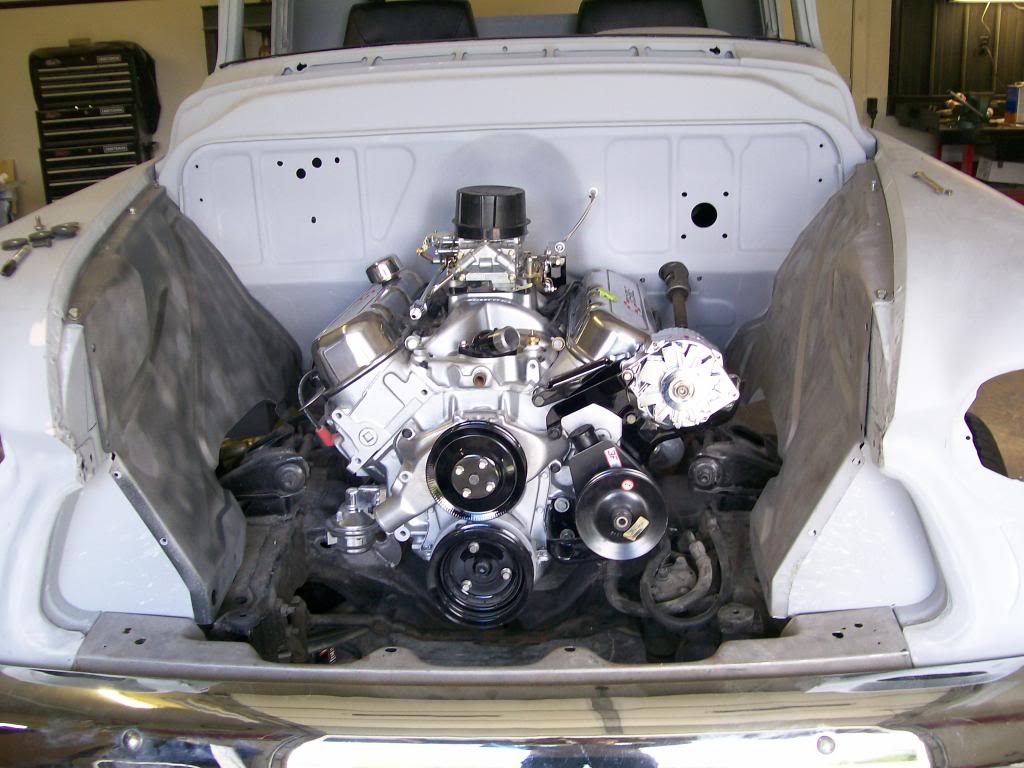
With the engine compartment gloss black, the engine should stand out all the more.
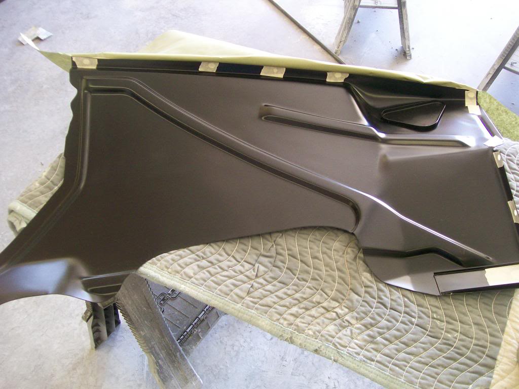
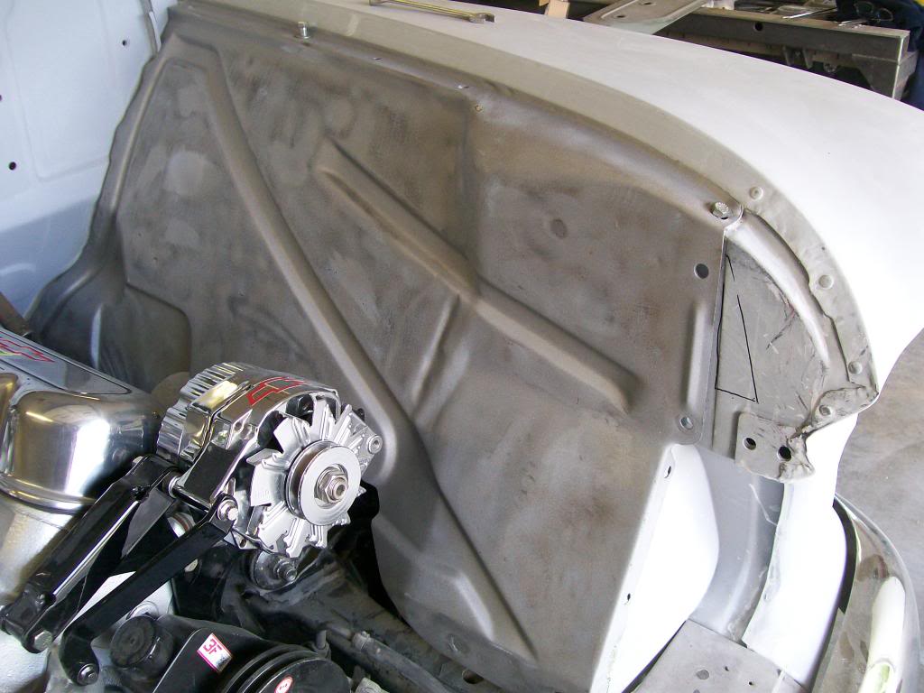
The panels were not meant to be cosmetically appealing when they were made, they had holes, bumps and wrinkles in them. In gloss black, this would look terrible.
The sandblasting hides stuff but you can see much of the waves and wrinkles.
First I wanted the bottoms to be semi gloss black. You can see some of the waves in the far panel. This being the underside I wasn't too concerned.
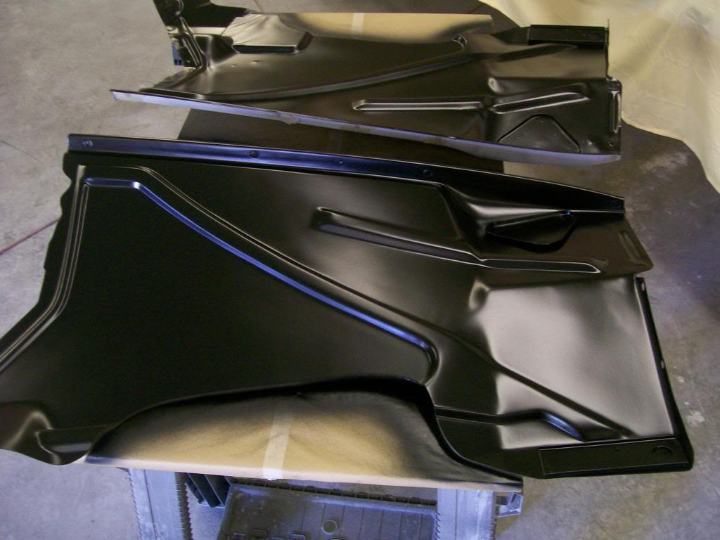
I gave them a couple of days to dry then carefully taped off the back side being sure to cover any bolt holes also.
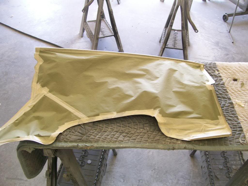
Beware, if your gonna spray base coat clear coat, the base coat will have no shine as seen in this picture. The idea is just to get color on the panel.
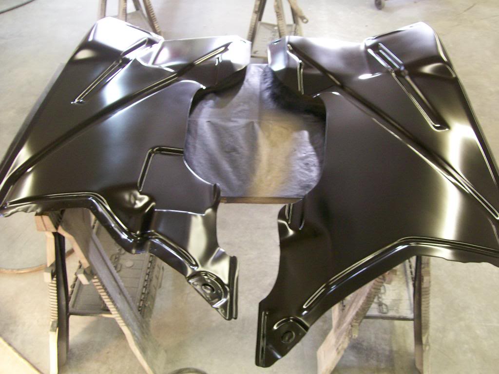
The clear is where the gloss will come from.
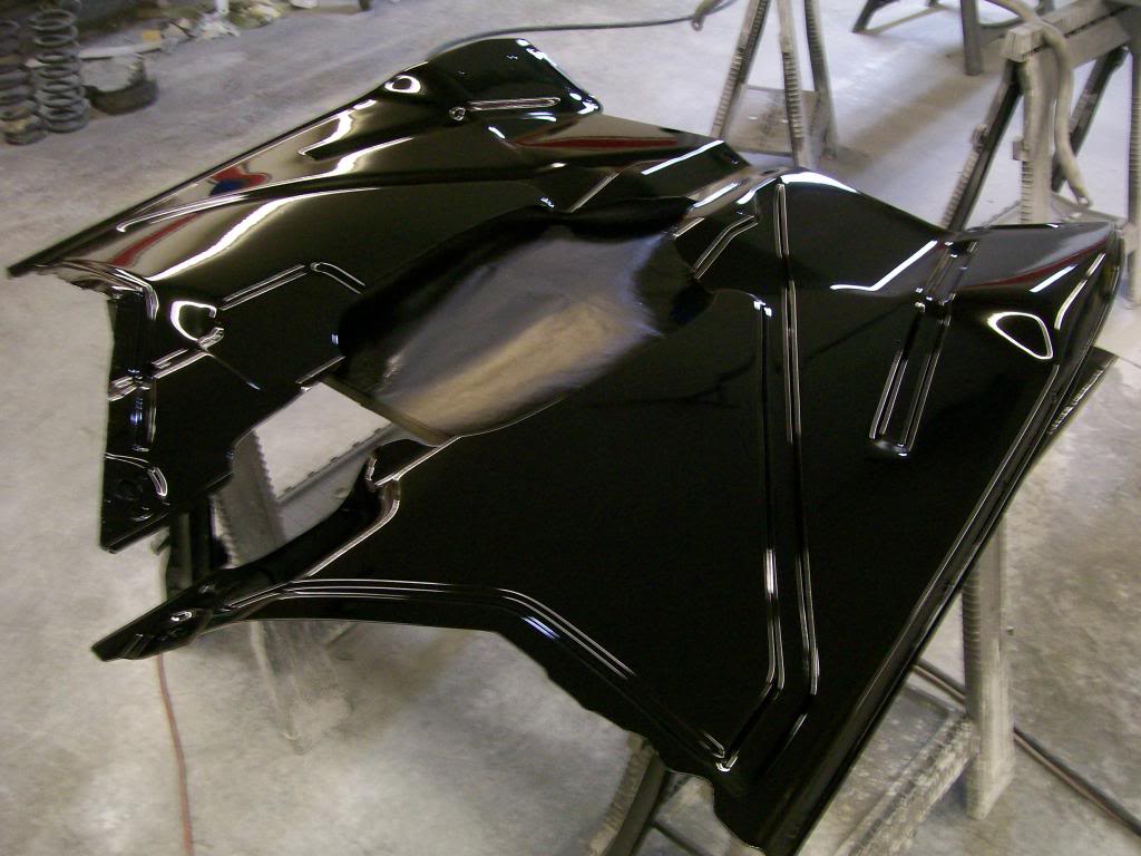
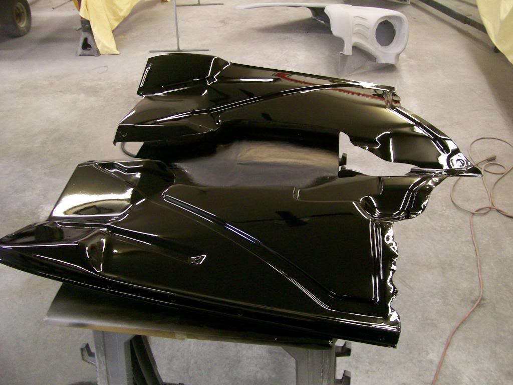
I like the gloss, but I want the best possible reflection I can get. I could stop there but I can do better, I'll get to that next.

5-14-2014
So far I've done all the usual body work process on the inner panels, sandblasted, welded, body filler, epoxy primer, high build primer, block sanded, epoxy primer as a sealer, black base coat then the clear. E-gads, that's a ridiculous amount of work.
This is where most projects finish, but I'm going one more step, today they call it "cut and buff", we used to call it color sanding, then buffing. I want to best possible reflection, so here goes.
No matter how well you spray there is gonna be at least the slightest bit of orange peel, or specks of dust. Even if you get past both of these issues there is still gonna be the slight haze from when the clear dries. It's when as the clear dries, solvents raise to the top and crate the slightest haze that removes some of the clarity of the finish.
These issues can all be taken care of by cut and buff, but, it is very labor intensive. I usually start with 1500 grit paper and water, sometimes with a slash of soap to help lubricate the surface while sanding.
A look at the sanding process on the nice clear coat sprayed a couple of days before.
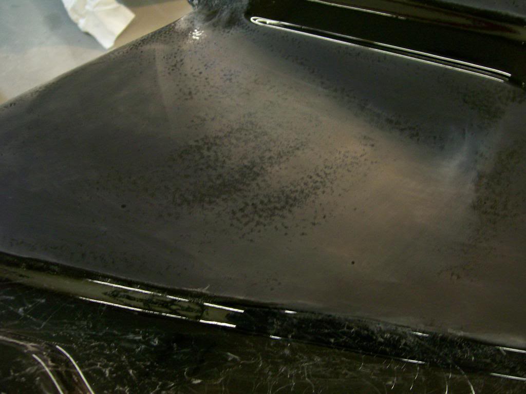
The sanding really tells a story of the imperfections in the surface. I want the whole panel sanded til I have no shiny spots left.
Even these small spots I want removed and you can see a small speck of dust, it too will be gone when done.
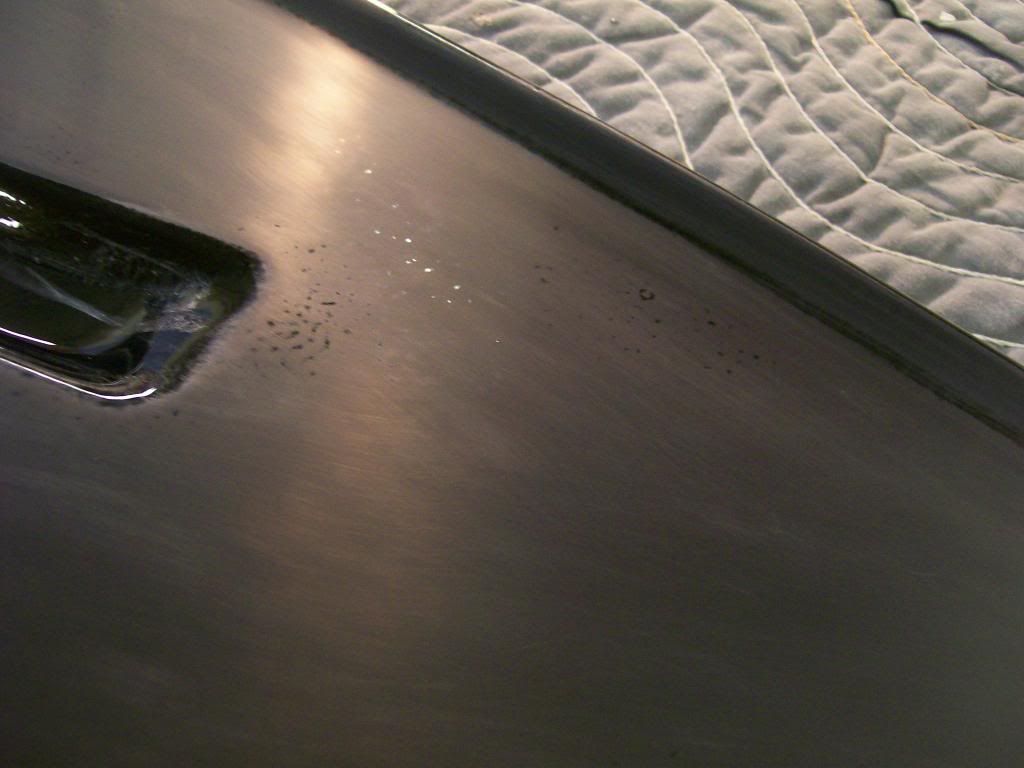
The first panel I did in sections, here is one section done with 1500 grit. I will go over it with 2000 grit to remove the 1500 grit sand scratches. A very small difference between the two papers but after this we go to buffing compound and the less depth of scratch, the less buffing needed later.
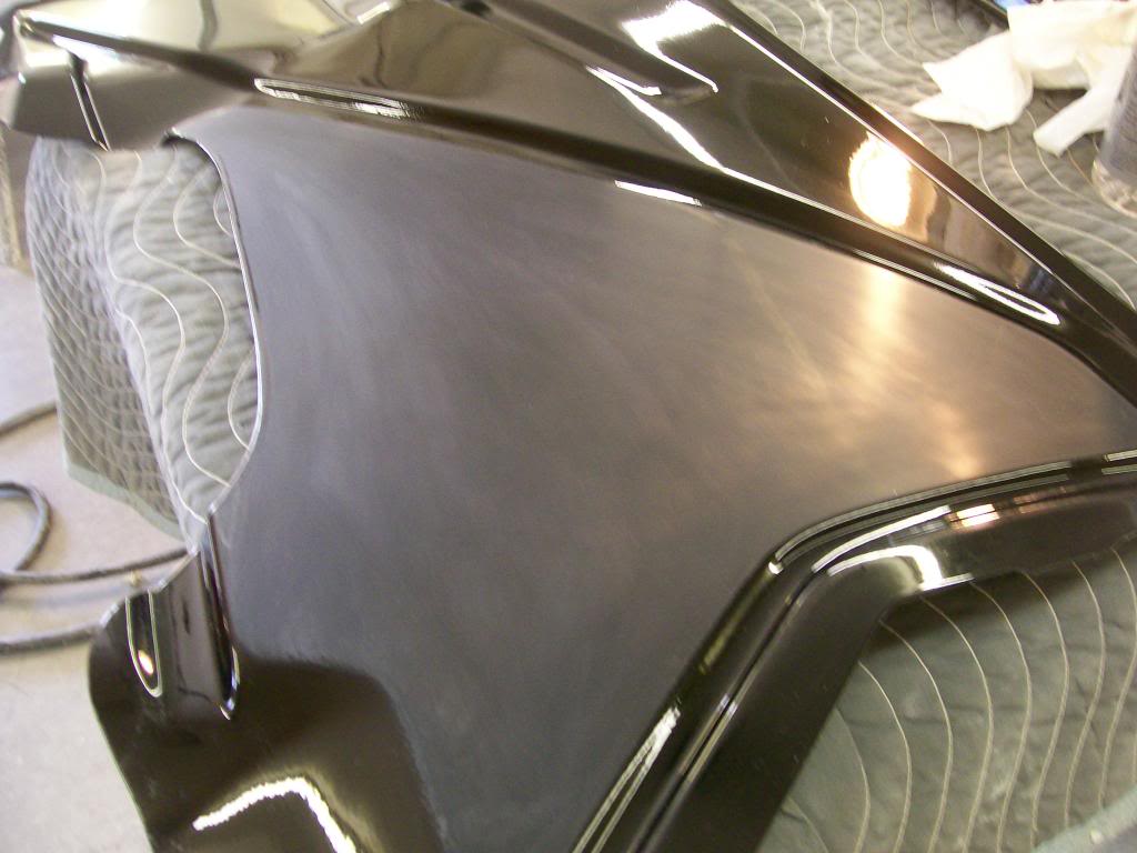
Now the same panel that was sanded to 2000 grit and buffed.
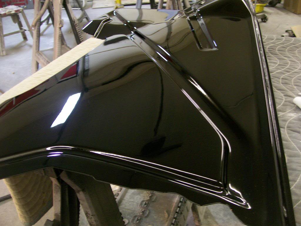
The camera as usual doesn't like all black so it turns grainy in the picture but I how the clarity shows.
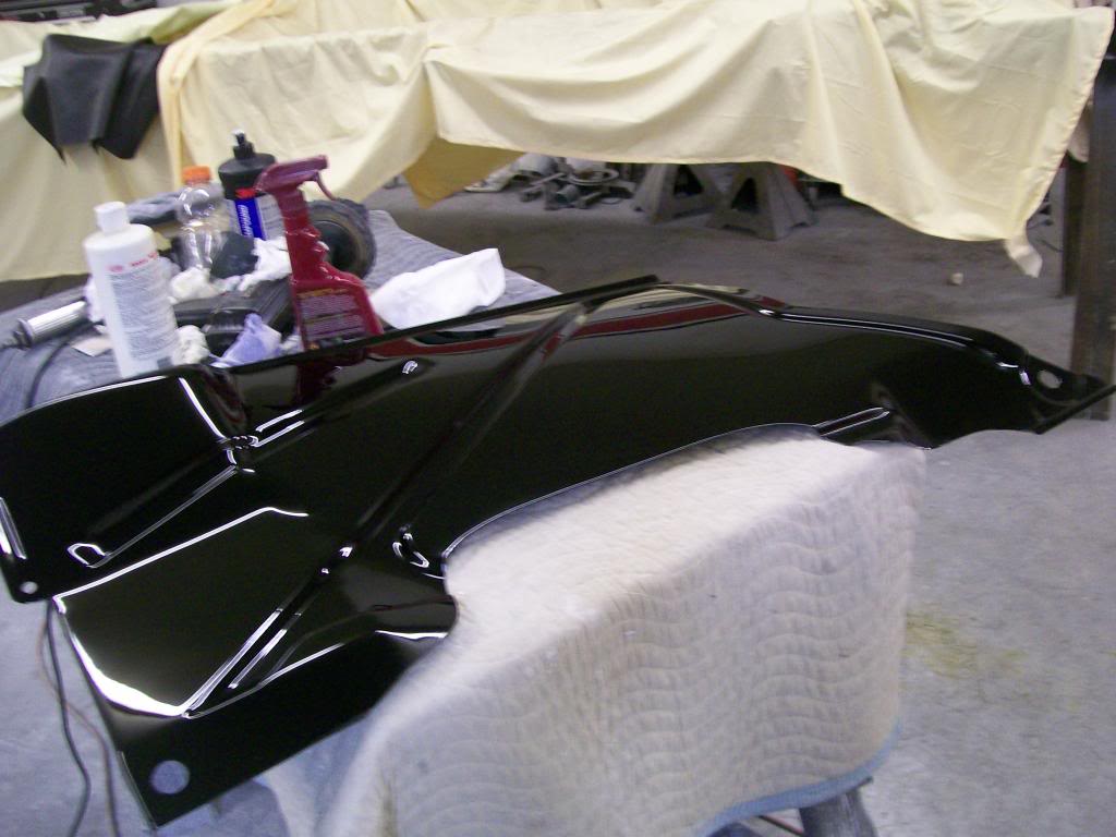
In these pics I haven't done the indentations, but in real time I sanded the indentations with 2000 grit and between the buffer and by hand I got the indentations finished also.
Here's the fragile areas.... watch the edges , during sanding, I try to stay away from all edges, I do the buff, if there are obvious spots in the edges that need sanding, I focus on those individually.
Next. I did these by hand sanding, I've learned to watch how to apply finger pressure, you can actually leave finger rows in the finished product if you push your individual fingers into the surface while sanding. When I do the outside of the truck I will use a small soft rubber/foam pad that I will wrap the paper around for all the main flat areas.
Again, watch the edges while buffing, the buffing pad will hook an edge and dig in. I have an electric adjustable speed buffer, quite frankly I often prefer my fully variable air buffer/grinder. I'll set the regulator down around 70 or 80 pounds. This way on the flat areas I have plenty of power and speed, yet if I start to hook or dig in, it looses rpm real quick.
There we are, one more aspect of vehicular restoration covered.
5-20-2014
lovett86, thank you, and thanks for checking in.
Cuder. I hear ya and I'm one step further than you, " I just want to driveit!"
Now that the frame is painted and I've painted the rear axle and most of the suspension parts I'd like to have a rolling chassis. Before I bolt up the rear axle I'd like to install the internals now before it's back in place.
One thing often used to describe the gearing in an axle is by the ring gearteeth divided by the pinion gear teeth. In this case I went from a 3.08 to a 3.73.
What, in reality we are changing is the diameter of the two gears. Even more yet, it's pretty well the pinion diameter that changes and the ring gear diameter stays the same. A 9" ford is a 9" diameter ring gear. An 8'5 GM 10 bolt is a 8.5" diameter ring gear.
Let's look at the diameter difference of a 3.08 vs a 3.73. The 3.73 is on the left.
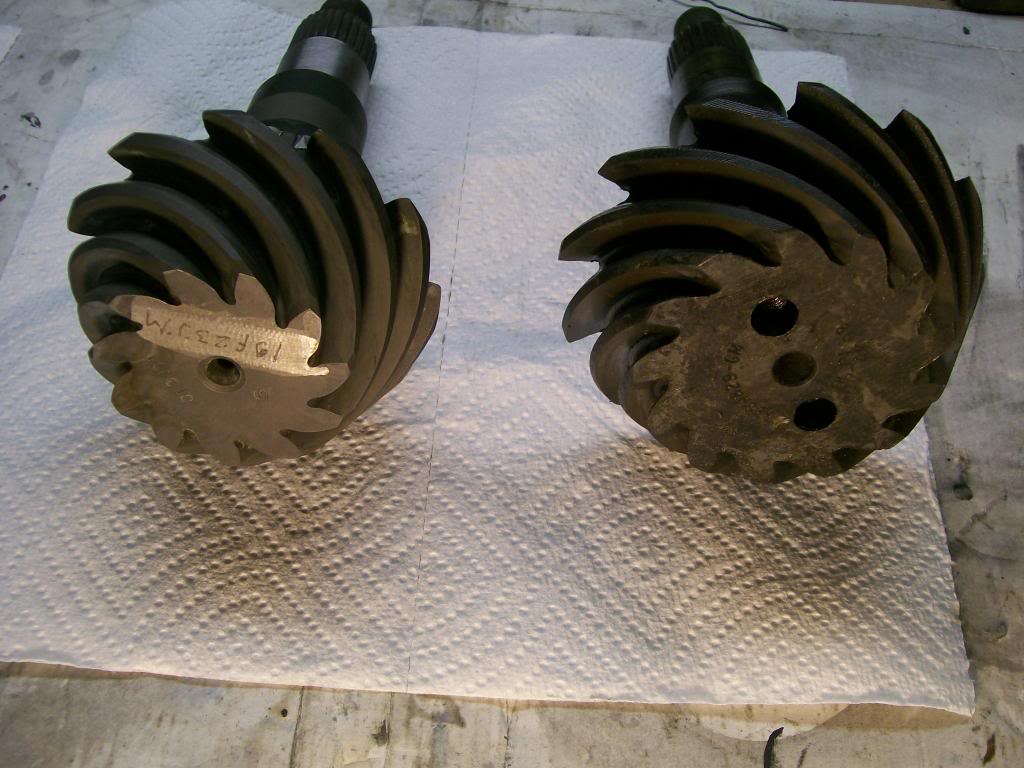
Basically the same as your old dirt bike or ATV, the smaller the counter sprocket, the more low end torque you have. In my case, I gain low end torque and lose top end, or at least I have a higher rev at highway speeds. This is where the over drive comes in, and reduces my RPMS back down to a better range on the highway.
Picture this, the diameter of the ring gear stays the same, the teeth change only to match the teeth cut on the pinion, but what does have to change is the thickness of the ring gear. The difference of the 3.73 means the ring gear has to be thicker to make up the space of the smaller diameter pinion gear.
Now when you hear the topic of the carrier has to be changed to match a certain gear change. There is a point to where the ring gear gets too thick or too thin and the carrier has to have a different stagger or off set to get the ring gear and pinion to be within thousands of an inch again.
Ahh yes, the ole crush sleeve design, lets look at one.
There it is, the small sleeve in front of the smaller bearing.
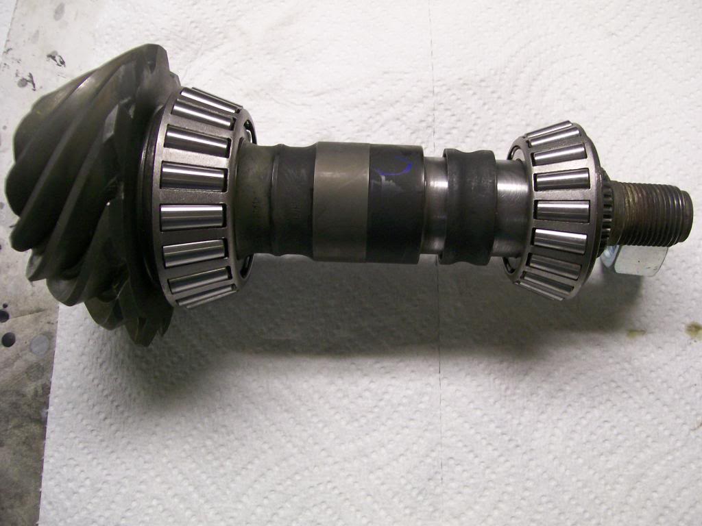
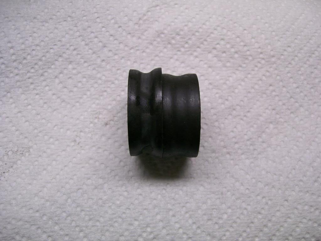
This sleeve is gonna be what creates and holds the preload on the two bearings. It will be crushed slightly then stay that way as a permanent spacer of the exact size it will be crushed to during installation. This takes the place of installing thin shims to create the preload on the two bearings such as the DANA 60 had with the Willys.
Here is a used/crushed sleeve and a new one.
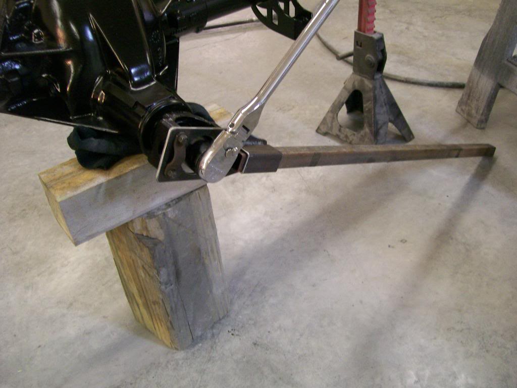
This thing is a mother henner to begin it's crush as you tighten down on it. I made a firm bracket to hold the hold while tightening down on it. I believe it's around 300 foot pounds to begin the crush.
The idea is to create a drag/ preload that can be measured by it's turning resistance. The book called for a rolling resistance between 14 and 19 inch pounds. Once the crush sleeve begins it's crush and the free play is gone, the bearings begin to preload quick, only very short movements of tightening the nut are needed to make a difference on preload.
Using an inch pound torgue wrench we check the turning resistance.
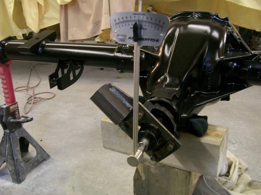
These next pics are as I'm slowly turning the pinion to get the rolling resistance.
Just making contact with the bearings and the crush sleeve.
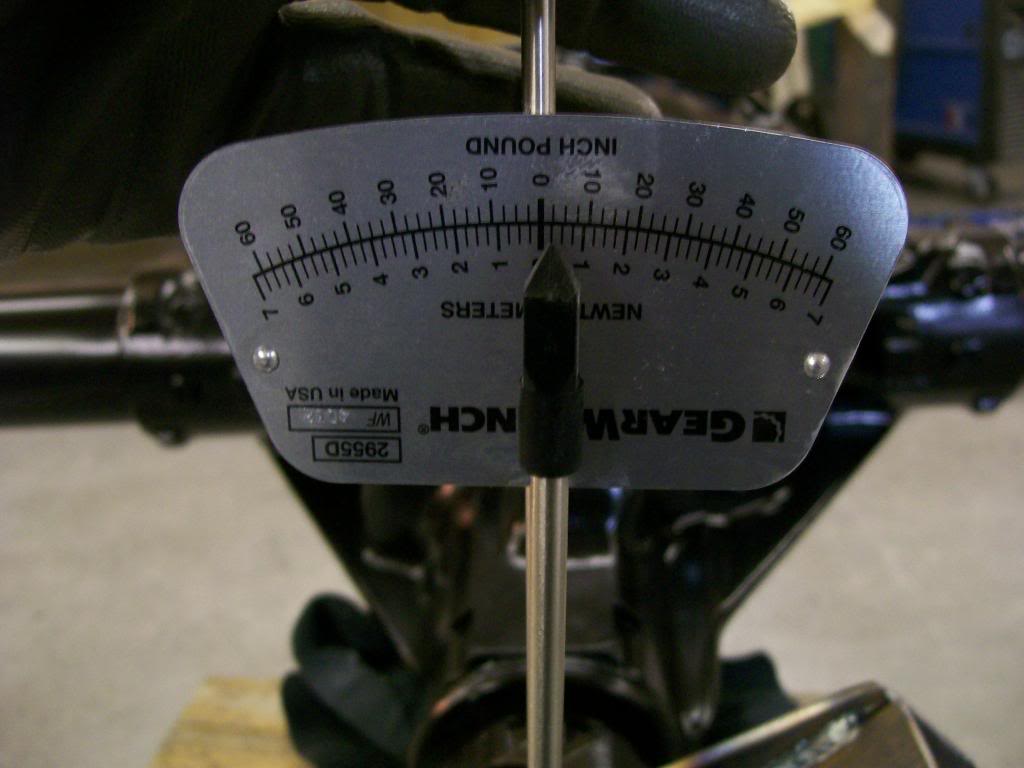
Very very slight turn of the pinion nut.
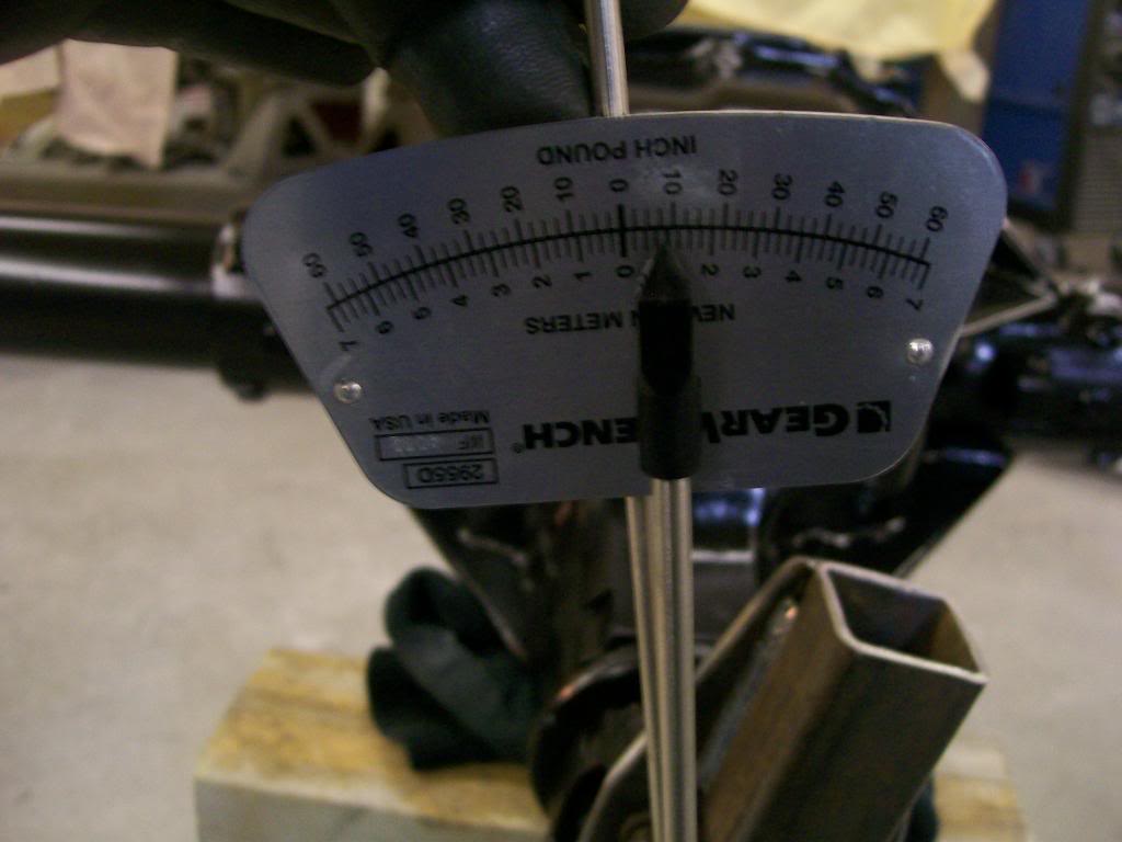
Just a very slight more turn. Between 14 and 19, I'm happy with 15.
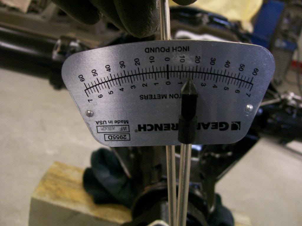
Ok. I've already determined the shims for the carrier some time back, so I'll set it into place. This axle also got some moser performance axle shafts, so it should be ready for a beating.

Wow, I thought for sure this would get me to page 100. lol
