You must be logged in to rate content!
14 minute(s) of a 668 minute read
10-12-2012
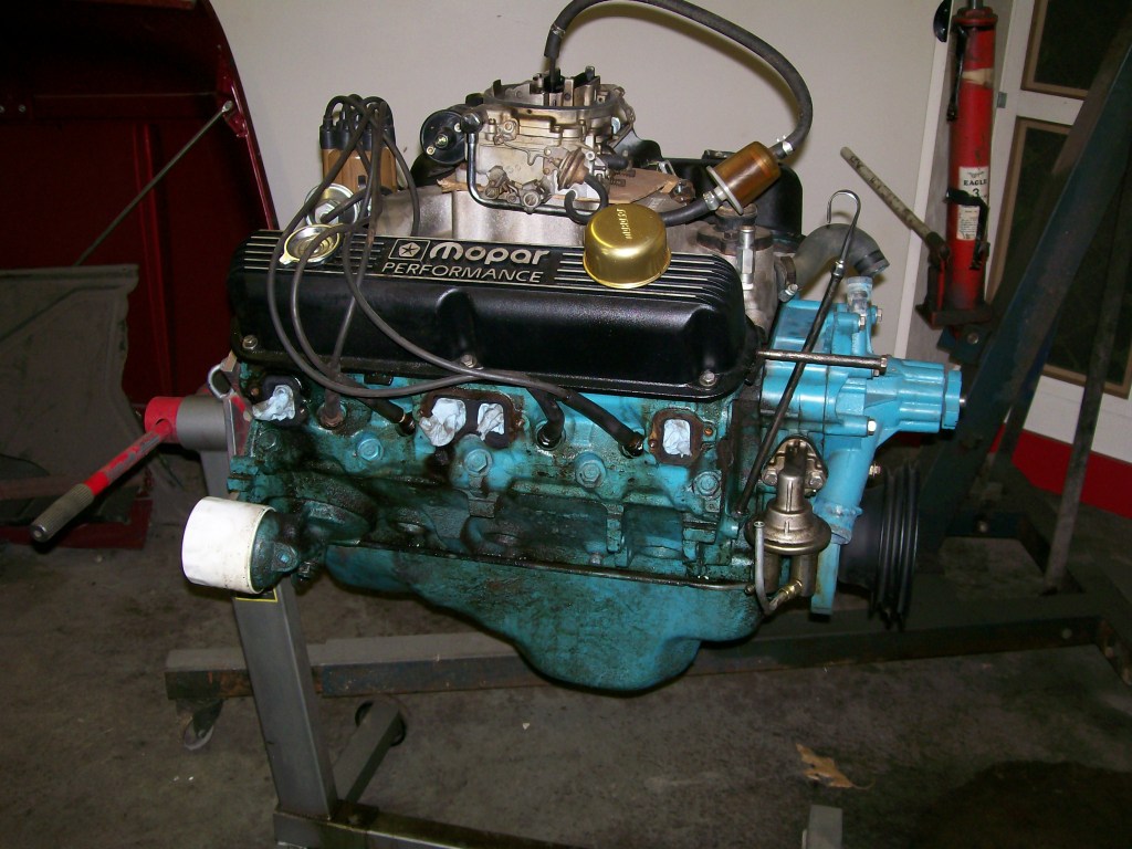
Here's a look at the 318 out of a 1973ish Dodge Dart.
A friend of mine bought the car this summer, the body is in great shape and it's a very light car. This 318 powered the car pretty good but the oil pressure was a little low and he could detect a slight knocking sound.
In an emotional whim he yanked the engine out and brought it over to my shop. We put in on the engine stand, flipped it upside down and removed the oil pan. We don't know the past of this engine so as I'm removing parts I'm looking for clues as to what the engine has been through.
Here it is on the engine stand.
What we found is an engine that needs some machine work, rod and main bearings, cam bearings, crankshaft work, well, you get the picture.

10-14-2012
J-Quad, dead on perfect question. How much to spend.....How much can you spend. Yes, it's now all about the money.
This engine rebuild has taken a few twists along the way. I'm the main rebuilder but I also have to be the one to identify and explain what needs to be done. This is not always easy, I always know that the build has a dollar limit. As for this engine, the deeper I get, the more I see it's gonna cost.
Honestly, it's a 318, there is a limit as to what you can get out of a 318. Chrysler has a 340, real hard to find, and a 360. Both will bolt into the same place as the 318. My point, I'm thinking of the amount of money put into a 318 vs the same money put into a 360, but for now, I still have to get the 318 apart.
For those of you familiar with rebuilding and engine, this will be boring.")
For those afraid to remove the oil pan because you're not sure of the dark mysteries hidden within, perhaps this will shed some light for you.
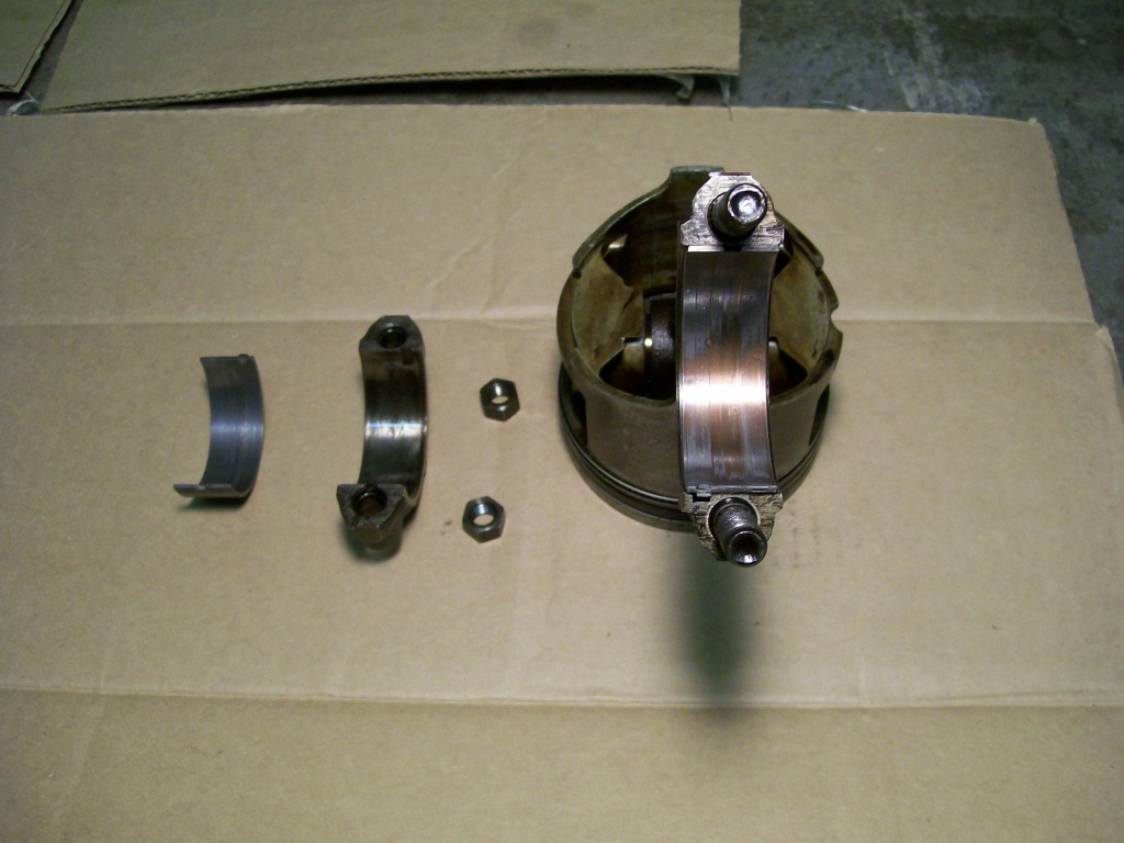
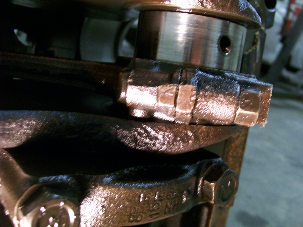
Starting with the piston, connecting rod and the rod bearings

To begin with as I did the teardown, the rod bearings, once I removed the cap, showed an excessive amount of wear. Now yes, as J-Quad mentioned, it is an old engine but as I'm looking, I see more than normal wear, I see small specks of foreign matter imbedded into the soft bearing material. I now feel this engine has been apart, the factory does a much better job of assembling a clean engine.
The bearing wear is not the big issue, it is the crankshaft that is the issue. The bearing replacement is part of a rebuild, the crankshaft can be polished and reused. In this case, it needs to be replaced. The small specks had wore small grooves into the crankshaft.
Here's a closer look at the bearings. The aluminum color to a copper is normal with major milage on the engine, it's the specks and grooves that is not good.
10-15-2012
I mentioned small specks imbeded into the rod bearings in the last post, this next picture will show the specks better.
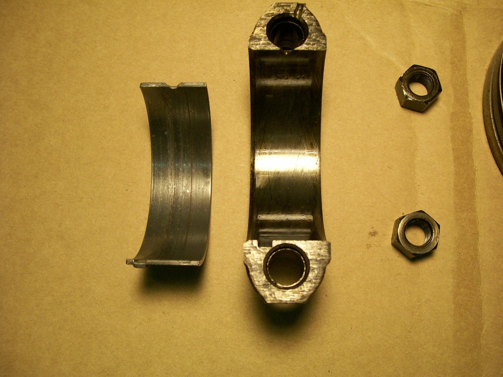
Next up is a picture of the number 2 connecting rod. By this picture I can tell that this engine has been apart before. Just as when I removed the carrier from the dana 60 in the Willys, I used a center punch to mark the bearing caps to ensure that I put them back together the same way.
The person who rebuilt this engine did the same thing by putting two marks in the connecting rod cap.
Although making the mark in the rod cap is a good habit, it is best to look at the rod closely. At the factory in most cases, they will actually stamp the cylinder number into the rod and the cap and by lining these two up, you know you havent assembled them 180 degrees off.
Attention............. Never but never disassemble the engine without comfirming such things as the numbers on the rods. Confirm that the even number cylinders and the odd number cylinders face the right way concerning the stamped numbers.
If you assume anything is correct during the disassembly, during the reassembly is the wrong time to see you have two connecting rods with the number 4 stamped on them.

10-16-2012
Still focused on the connecting rods, I'm sure many have seen where there are pieces of rubber hose put on the rod bolts.
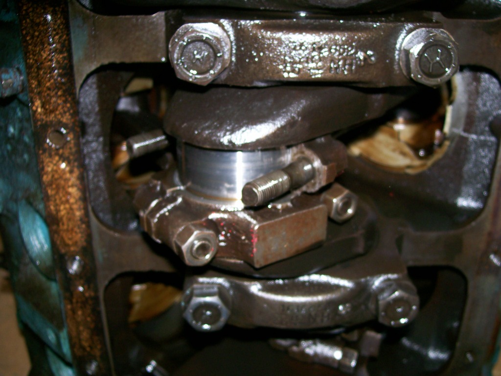
The pieces of hose serves two purposes.
1) When removing the rods and pistons sometimes you have to use something with a soft end to tap the bottom of the piston to get it out of the cylinder. While tapping the piston the rod can move around a bit and the sharp edges of the threads of the rod bolts can touch the crank journal and leave a mark, this is not a good thing, be careful and slip some hose over the bolts.
2)By using hose on the rod bolts during assembly the hose will keep the rod bolts from marking the crank journal. Also by using pieces of hose that are 6 or 8 inches long, the hose will help guide the rod toward the crank journal.
Recall in the last post I mentioned to never assume the engine is assembled properly that you are disassembling.
In this next picture I have two cylinders that are next to each other. By looking at the picture can anybody tell me where the last person assembled this engine incorrectly?
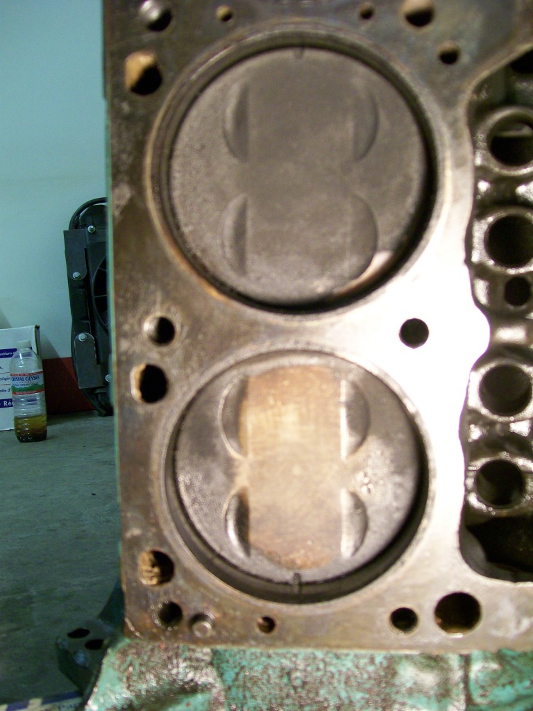
Good eye,
The mark on the pistons represent forward. Somehow when this engine was assembled last time the builder put this piston and connecting rod assembly backwards.
As I mentioned before, don't trust the last builder. When we tear down an engine, or in many things we do in life, it is our perfered outcome that determines how view the situation.
At times in life we are so focused on an outcome, we overlook the red flags that tell us to head a different direction.
I'll explain.
 When I tear down this engine if I go with the primary mindset that this will be a positive forward rebuild, I will unconsciencely overlook the problems and issues. If I go in with a negative mindset, I am more likely to find the hidden problems inside this engine. Especially if the owner is there during the disassemble, I don't have to convince him of what needs to be done, I am teaching him along the way and with a flashlight and a long screwdriver I can point out all the issues.
10-17-2012
For the next focus on this engine I'm bringing back a picture from earlier.
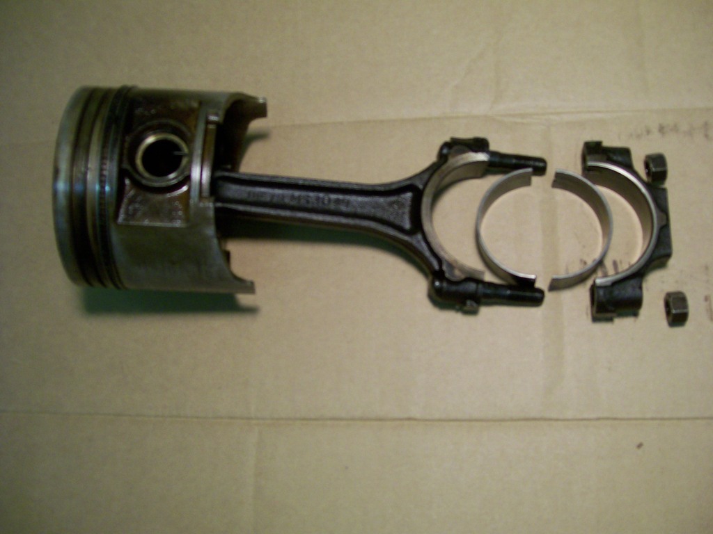
This time I'm looking at the piston itself. You can see grooves cut into the piston, it is these grooves that the piston rings are fitted into. The piston castings between the ring grooves are called lands.
I mention the rings and the lands because they are the what stops this engine from disassembling easily.
I blame the rings but it's the wear that the rings have caused over thousands of miles of use. The rings are made so they will naturally spring outward and fit very tightly against the cylinder wall. Honestly, it's an amazing amount of friction being created as the engine is running. Then considering the amount of heat from the combustion happening above the piston and rings. We can thank the oil manufactures that our engines don't just sieze up after a short time.
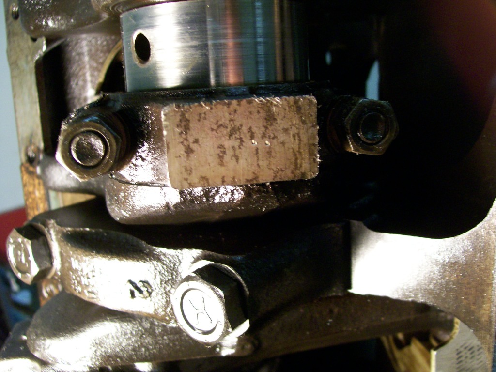
In the next picture I have a piston ring fitted into the cylinder. Looking at the cylinder itself I assume this engine sat for a while since I see a rusty residue in the cylinder wall.
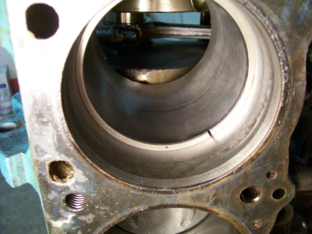
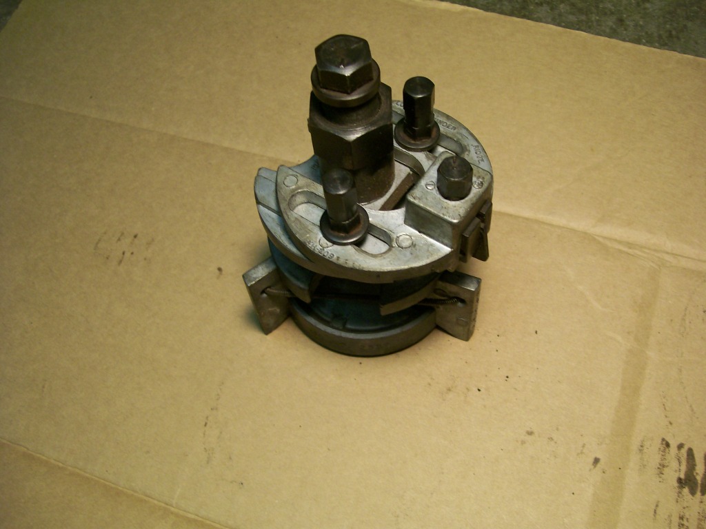
In the above picture I have already used two tools to demonstrate to the owner. The first tool was needed to even get the piston and ring assembly out of the cylinder. The tool is called a ridge reamer. It has a three legged base and an adjustable cutting edge.
The problem is, the rings have worn away material from the cylinder wall over time. This wear has stopped about 1/4" from the top. With this wear zone when I tried to slide the piston assembly out of the cylinder it stopped when the top ring hit this ridge. I have two options, beat the piston out, but I have a good chance of damaging the piston, especially the piston land which will take the abuse of the ring pushing down on it.
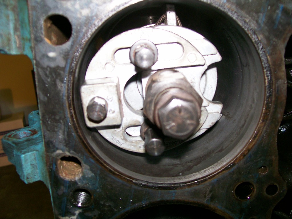
Or... using a ridge reamer. By turning the crankshaft so the piston is at the bottom of the bore I place this tool inside the cylinder. Once the reamer is in the cylinder I can adjust the amount of cut I want to make.
By using this ridge reamer I can cut away as much of the ridge at the top of the cylinder so I can slide the piston and ring assembly out of the cylinder safely.
In the picture with the ring in the cylinder you can see the freshly cut ridge. Down further in the cylinder it looks freshly cut also, this was not done by the ridge reamer. I used a cylinder hone to clean that up. I'll cover that tool later.
10-18-2012
Ahhh, I see where you're at here. Let's go back to the picture of the two side by side cylinders. Due to the discoloration of the tops of the two pistons, it looks like one piston has a dish (cup) shape to it. The two pistons are the same basic flat top design with the small valve reliefs cut into them.
The reason for the different colors on the top of the pistons was to see if the cylinders have been bored out in the last rebuild. If the cylinders would have been bored out, the tops of the pistons would normally have .030 or .040 or something stamped into them representing the overbore size. We just used a wire brush to clean the carbon residue from the piston to see if there were any stampings, this cleaning gave the illusion of a dish look to the piston in the picture.
It is the small notch on the outer parimeter of the piston that defines if it is in correctly. Alot of times the piston can be installed 180 degrees off and still work fine, it is the connecting rod itself that needs to be installed properly and if the piston has been pressed onto the rod properly, by having the piston face the right direction, we know the rod is facing the right direction during assembly.
Why the rod???? As we look down the empty cylinder we can see the crankshaft journal that the rod will attach to, at the same time we can see the same journal has another rod connected to the same journal from an opposing cylinder. In order for the opposing cylinders to share the same journal, sometimes the rod itself will be manufactured with a slight offset to it. The offset isn't so great that the engine can't be assembled, but the offset is enough to were the rod bearing takes more abuse than it would if it were installed correctly.
I have to get a few more pictures, but I will show how this 180 degree error caused incorrect wearing on the bearing.
Just for conversation......Weightwise on a flat top piston and dished piston probably, in theory, wouldn't make a noticable, if any difference with a spinning mass. If the weight is the same, the inertia would stay the same.
BUT. In the case of the engine, it is not just a spinning mass being spun by another power source. It is the power producing item that will spin the mass.
With this said, we would have one cylinder making less power due to the compression ratio difference. This one cylinder out of the eight could create a weak power point every other revolution of the crankshaft which to the human feel could be interperted as an out of balance condition.
Luke95, Thanks a bunch for checking in. On this end I can see where the pictures can tell a story I wasn't aware of. There may have been others thinking the same thing.
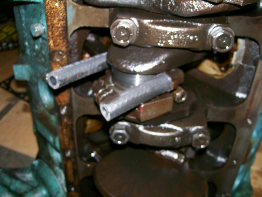
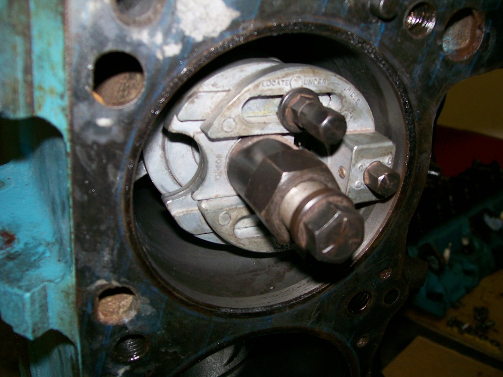
Trying to explain with words how the ridge reamer fits into the cylinder is difficult, so here's a couple pictures.
It is shaped with 3 legs that expand and clamp to the cylinder wall. Being 3 legs helps it to self center itself.
Once the reamer is set in the cylinder you set the top slider section so the cutting edge is up against the clyinder wall also. There is also a fine adjusting screw right near the cutting bit.
Now with everything everything set, by turning the large hex, the cutting bit turns and raises up to the top of the cylinder removing material from the ridge.
The whole ridge doesn't need to be removed to get the piston assembly out. I recommend not going too deep into the ridge while removing it. Just enough to allow you to get the piston rings past the ridge.