You must be logged in to rate content!
13 minute(s) of a 668 minute read
4-6-2012
Imped, thanks, glad you like.
Jeff88, ahhh, so you're familiar with the exhaust cut outs. I looked and thought about how I wanted the outlets to be on the open pipes. On the muffled exhaust I'll run it to the back and hide the tail pipes.
I concidered the idea of doing the same thing as you did and running to the front of the rear wheels and having turn downs. My problem is the truck has a step side bed. The step in front of the tires blocks my ability to run pipes the way I'd like to.
Here's the best part.... Sometimes when we run into problems, we are forced to be more creative. I have come up with an even better way of finishing the open pipe outlets. It's a matter of personal preference when we modify cars and trucks, but I think my idea will work and look great when finished.
The truck should have a dual personality when done.

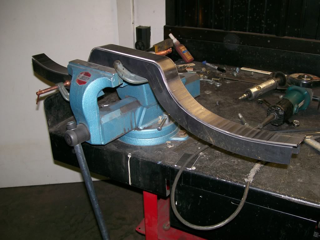
Now for a bit of fabrication. As I mentioned, I don't have a pipe bender, but there are times when I need to make slight adjustments, adjustments that are so minor that it's not worth having bent, but needed to get the fit I need.
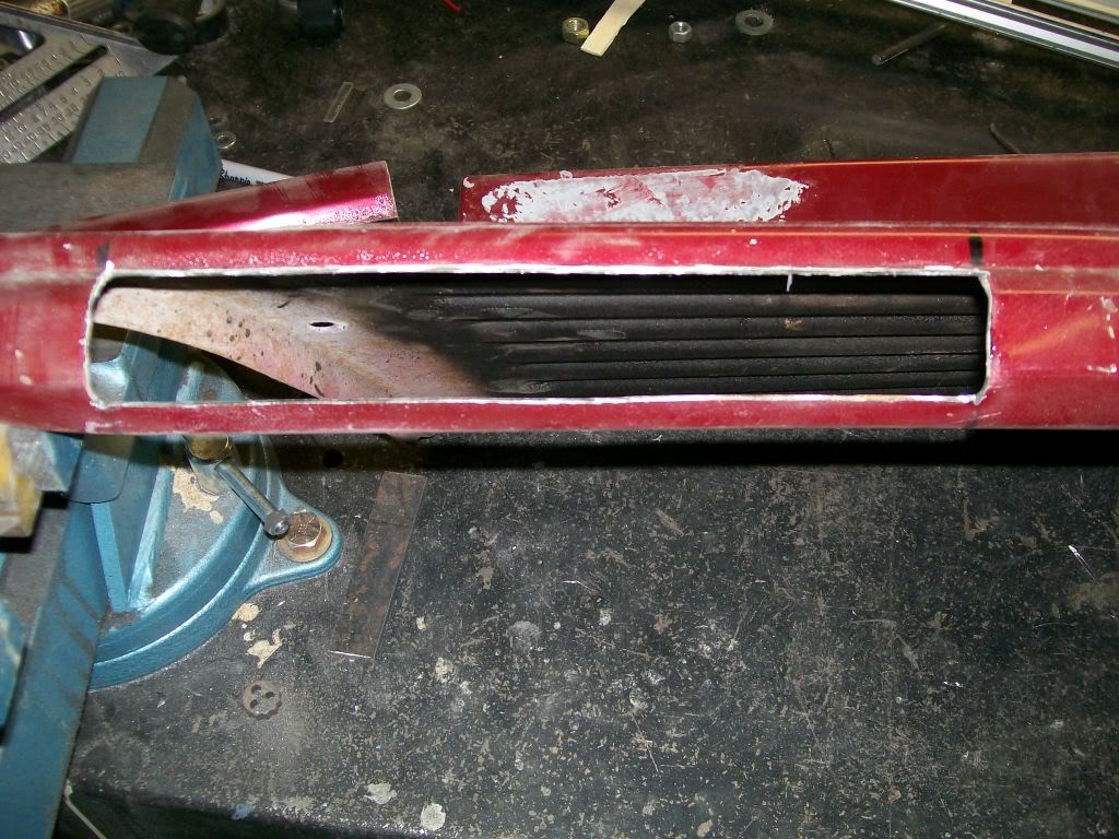
In this case the drivers side header flange is lower than the passenger side by aboout 1 1/4". I need the pipes to level before they get to the "x", otherwise things won't match.
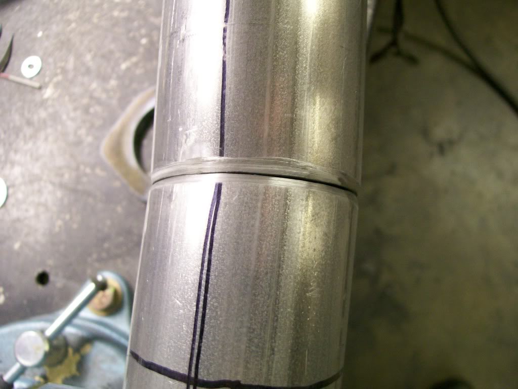
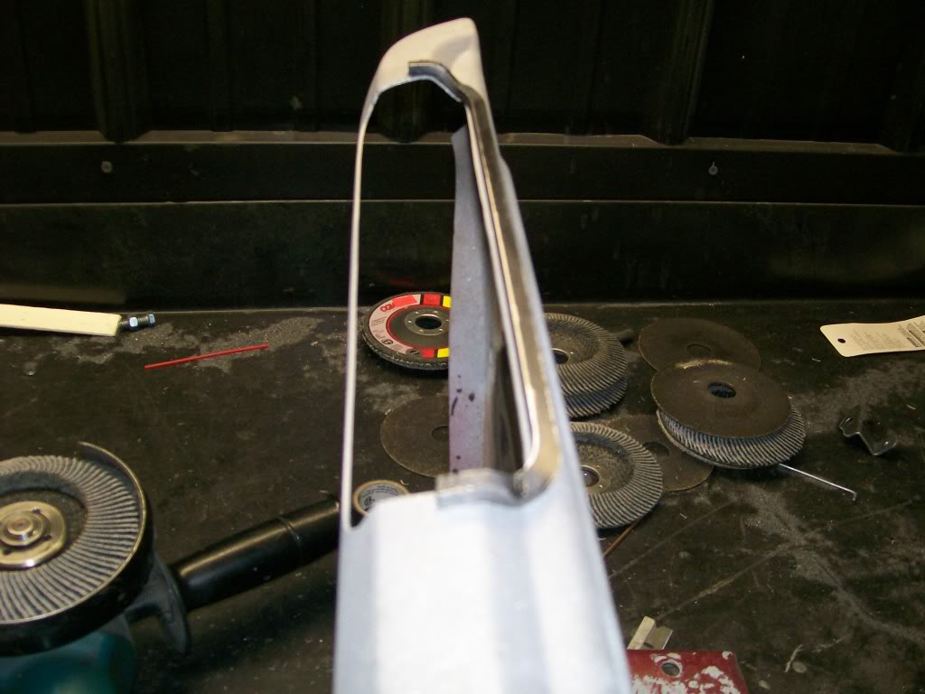
To raise the pipe on the drivers side I need two cuts. The first cut will be where the pipe will go upwards. The second cut will get the pipe level again.
Here's the two cuts.
I marked the cut locations, then used the 4 1/2" grinder with a cut off disc. I cut about 80 percent of the pipe. Then cut a wedge design out of the cut. Now I can bend the pipe together and check my angle. If I need more angle, I keep removing a bit of pipe and keep bending the pipe till I have my desired angle.
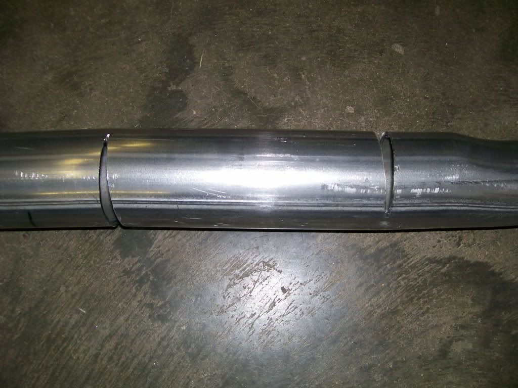
Here is the fit when I bent the pipe together.
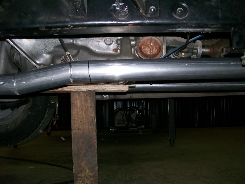
Here it is bolted in place. I got my raise in height. I can easily pop the spot weld and adjust if I need to.
4-8-2012
In the past I've done the suspence game and held off to the end to show the result I was working for.
Then there were other times I showed the end result, I think I'll show the result, I'm pleased with the result.

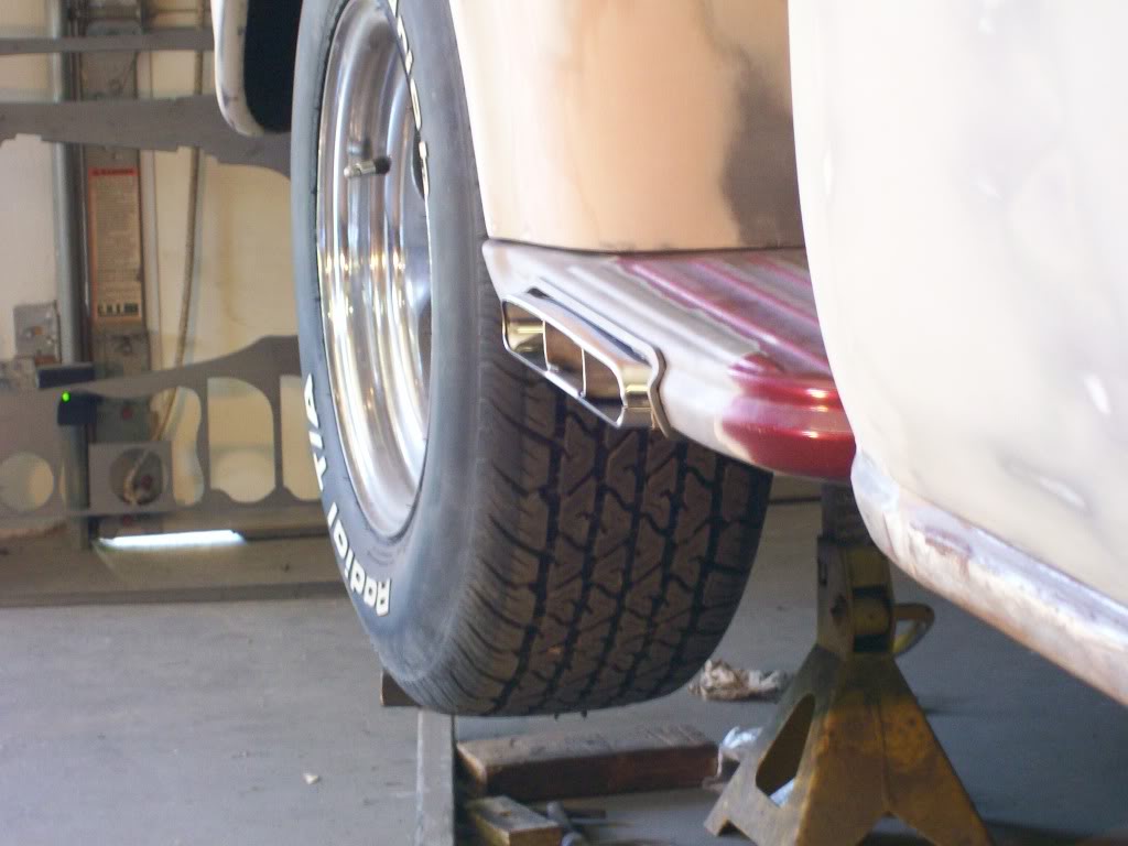
As I mentioned, I don't have the choice to run a down tube to the front of the rear wheel for the open header sound. I layed on the creeper for a while just thinking and thinking. Then as I was laying there I remembered in the Jegs catalog there were angle cut stainless steel exhaust tips. I opened the catalog and yes, there was my answer. They are rather expensive, but there are times when you feel something will seriously add to the project and you do what is necessary.
Ok. the idea is to have fairly quiet exhaust going all the way to the rear bumper. Then hide the tail pipes and this is the regular driving situation.
Then by the flick of a switch, these outlets which with the "x" pipe, will be like having open headers, having all 8 cylinders barking out both sides of the truck. Then, flick of a switch, and it's back to quiet time.
Now back to how I go to this point.....
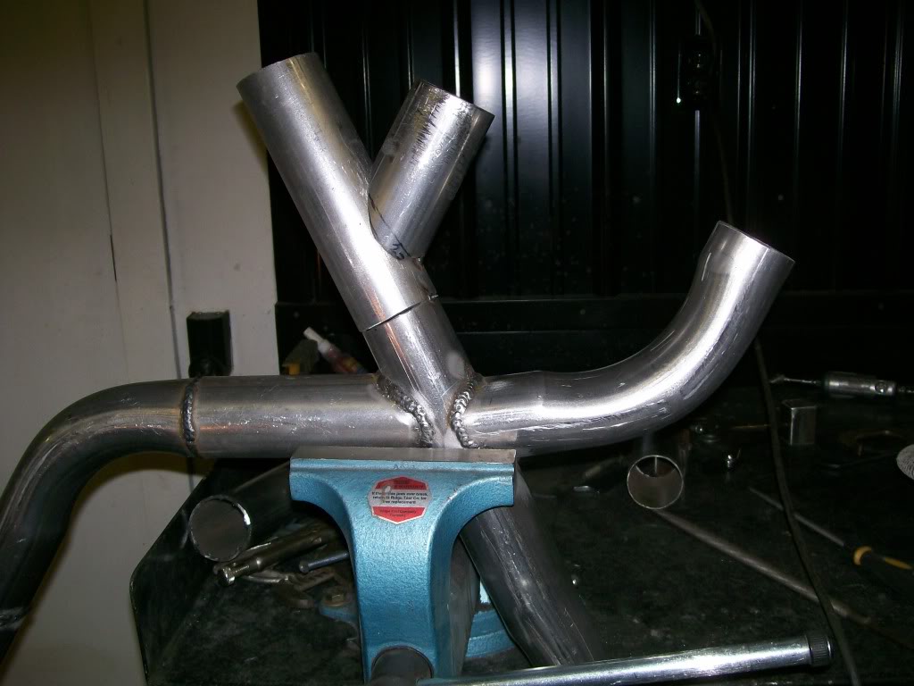
To make the "x" pipe I had to cut into one of the pipes.
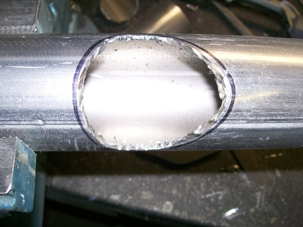
After cleaning up the edges with a rotary brrrr.
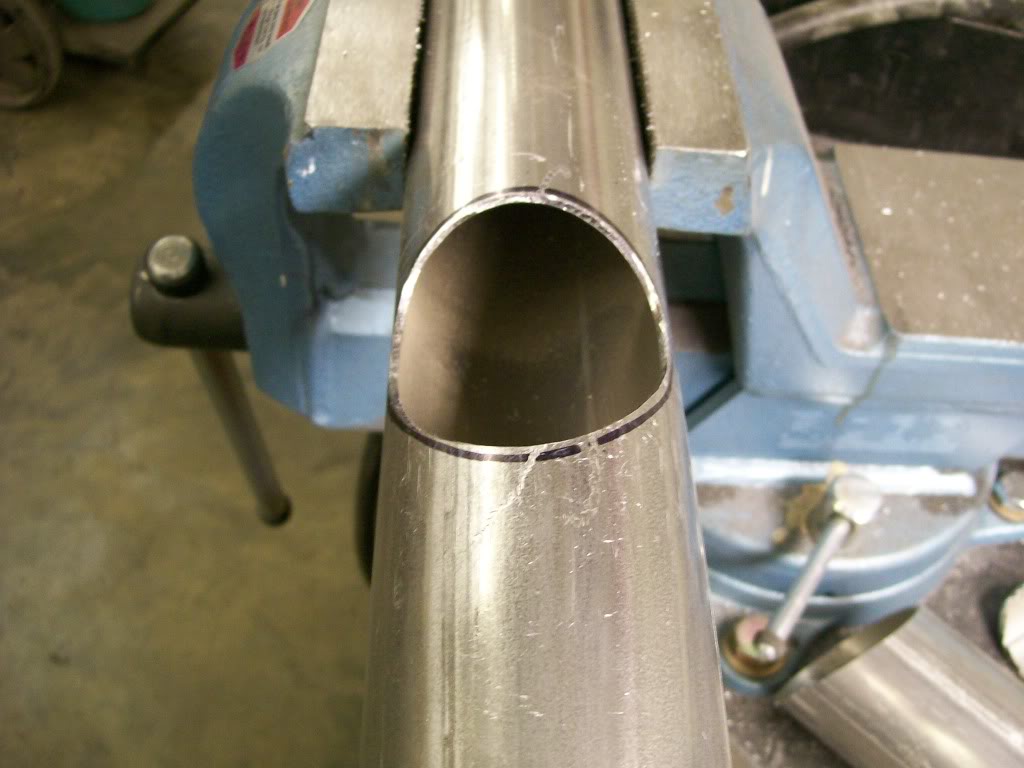
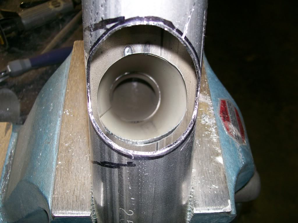
After I cut the second hole for the outlet of the "x", I got a good look at how the first pipe fit into the hole I cut.
4-9-2012
Yup, the 57 Chevy is for pa. He passed away over a year ago. Doing this Chevy together was something I was looking forward to, especially doing these neat little tricks and additions. Everytime I finish another part of it's build I imagine the grin on his face as he would have seen it.
pure82cj, the entire thread , I'm glad you enjoyed it.
I get a little nervous cutting into good sheet metal, but it has to be done. Here's the first step of installing the exhaust tips into the steps.
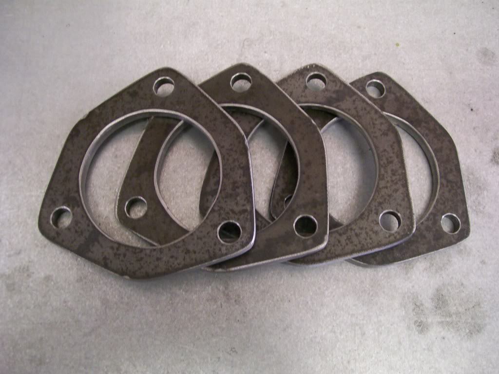
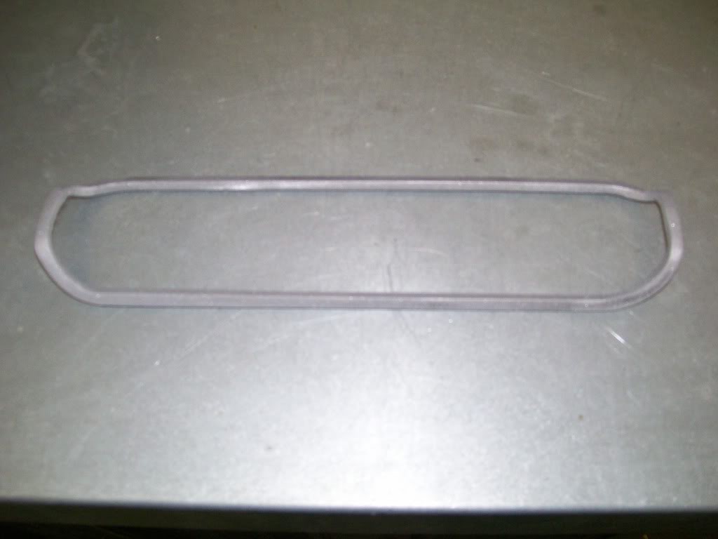
Back to building the trick exhaust. I need at least 4 flanges that fit 2 1/2" pipe. By using a gasket of the right size I used the torchmate to copy the design, then cut the flanges. I drilled the bolt holes using the drill press into one flange. Once I had the holes where I wanted them, I still had 3 flanges to go. The inside diameter mating and matching all the flanges is important. By fitting a 2 1/2 pipe through all of them, then welding them together, I can drill them all at the same time and they will match on assembly. After the welding I removed the pipe and drilled.
All four ready for service.
4-10-2012
The1AndOnlyBug, no problem, once I switched project vehicles on this thread I know it through a couple people off track.
Something I have to laugh about.... When you mentioned helping on the projects, there's been a couple of the readers of this thread who have mentioned the same thing.
Honestly, it'd be great to do some hands on training, I know the pictures can only teach so much. By many of the responces on this thread I know some of you would cherish the opportunity to spend some time learning first hand.
What I chuckle about is during the time I've been working and posting here, I've had 2 guys who started coming out from town to get some hands on training. They both ended up getting involved with girls and now are locked into relationships with the girls, if you know what I mean.

I won't say whether or not they are happy with their decisions, but they missed out on a great opportuity to learn some skills.
On to the build.
The exhaust tip is made of polisshed stainless steel so I wrapped it with tape while I'm working with it so I won't scratch it.
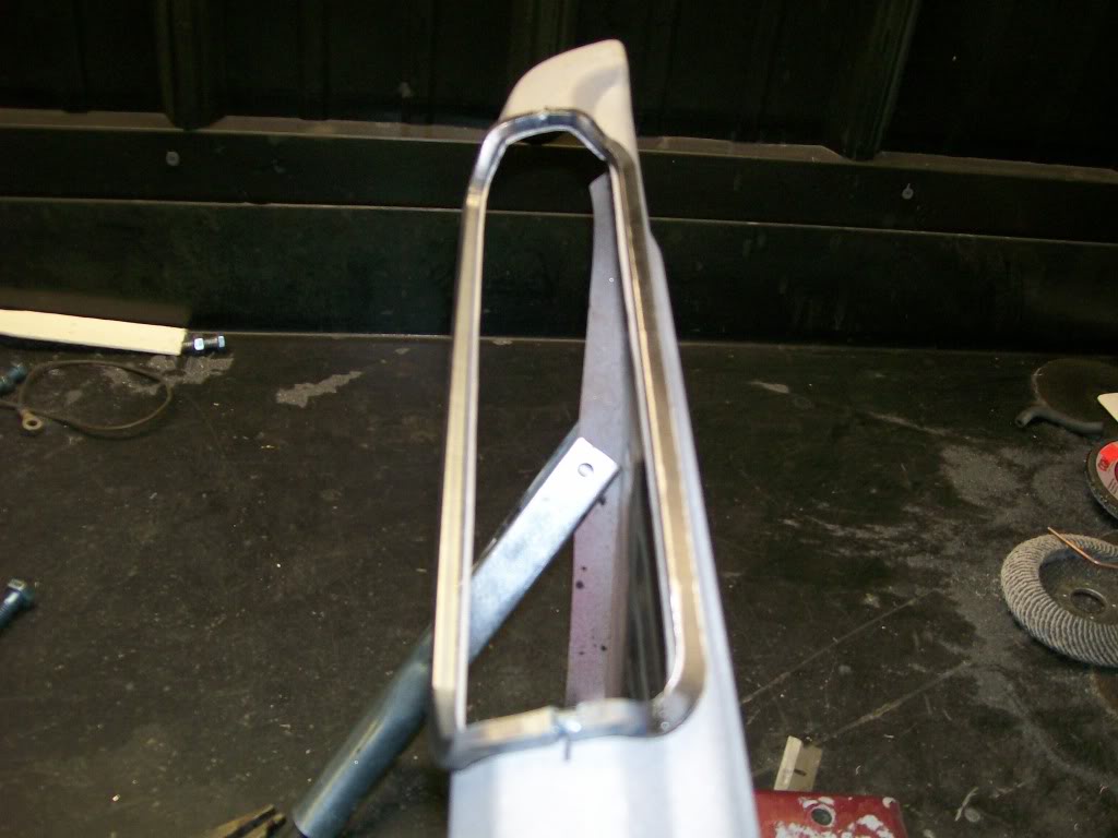
Once I cut the opening in the step for the exhaust to fit through I knew it needed something to enhance the opening. I figured a piece of moulding would look good.
I almost started shaping a piece of round rod, then I decided to use the torchmate to cut the design for the moulding. This picture shows the moulding and how it fits around the exhaust tip.
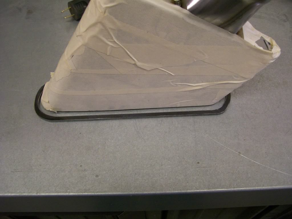
I'll show how I shaped the moulding to fit the contour of the step tomorrow, here is the end result after shaping it.
4-12-2012
Very well put. Know your passion and stick with it. If you bury your passion for something else, it will keep knocking til you open the door and let it be a part of you again. I speak from experience.
To shape the edging, once again I didn't want to use heat. Also I knew it was gonna to near impossible to bend and shape it as one piece. As you can tell by the next picture, I cut it in half.
Nothing fancy to bend the edging, nothing more that my bench vise and a hammer. Once I shaped the two halves, I used the grinder to bring the edges where the two halves meet to pointed edges. Then it was a matter of welding the two halves back together again.
Now the edging in place. It's the little details that make a difference. If I left it as cut sheet metal, it wouldn't look detailed once done.
4-13-2012
Here's the time I get a little nervous, it's commitment time, time to do the full welds. I need the lead pipes to be fully welded so I can move onto the rest of the system after the "x".
Once I've checked and rechecked the fit, I welded everything together.
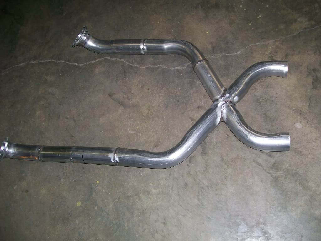
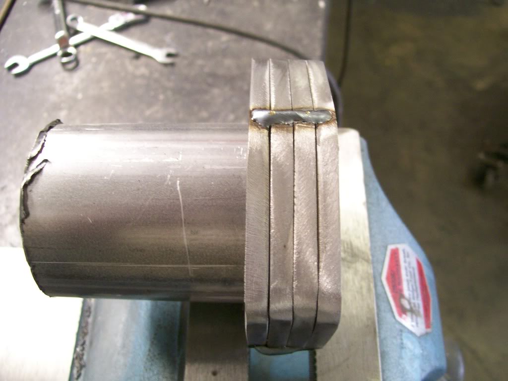
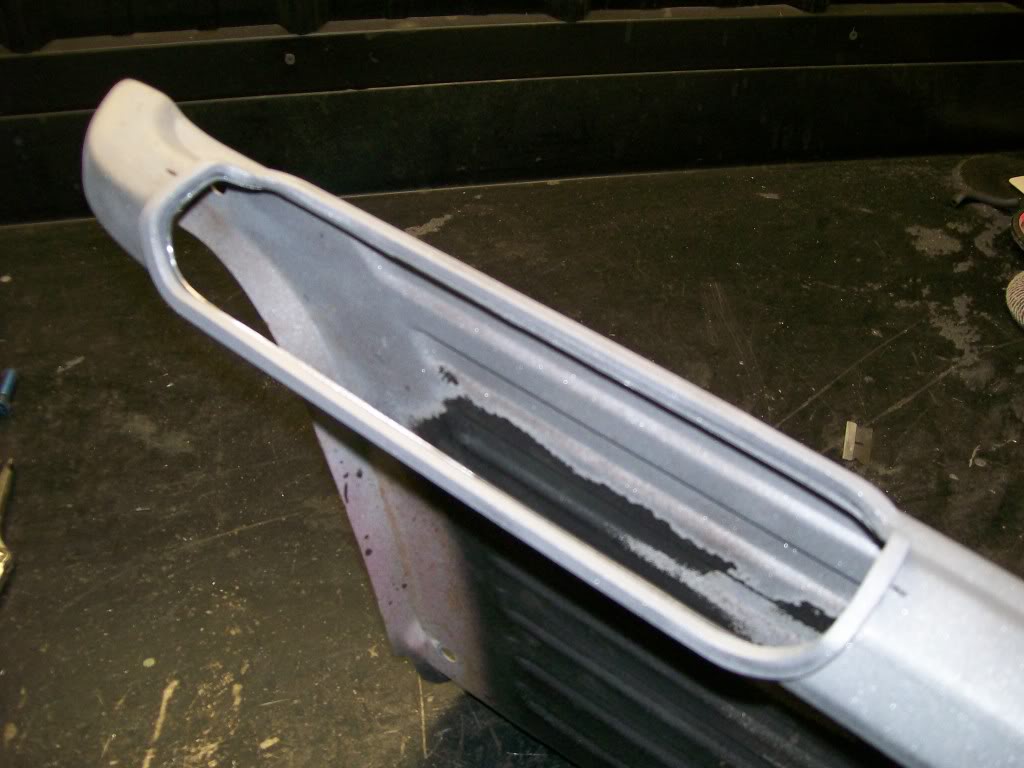
Just for an idea of what a monster I'm getting into, here's a picture of one side becoming a split. One outlet will have a muffler directly off the split. The other outlet will have a flange welded to it. Once the flange is welded in place, the cut out valve will be sandwiched between it and another flange and a pipe that will carry the open exhaust to the side outlets.
Don't worry, I'll have more pictures later showing more of the system.
4-15-2012
If anyone has noticed, the exhaust system doesn't have any humps where the pipes have to go over a crossmember.
Where most build the crossmember, then build the exhaust around or over it, I built the exhaust, then built the crossmember over or around the exhaust.
We've already been down the "crossmember build" road a couple months ago so I'll keep it short on this one.
Starting with the front and back sections after I had the torchmate do the cutting.
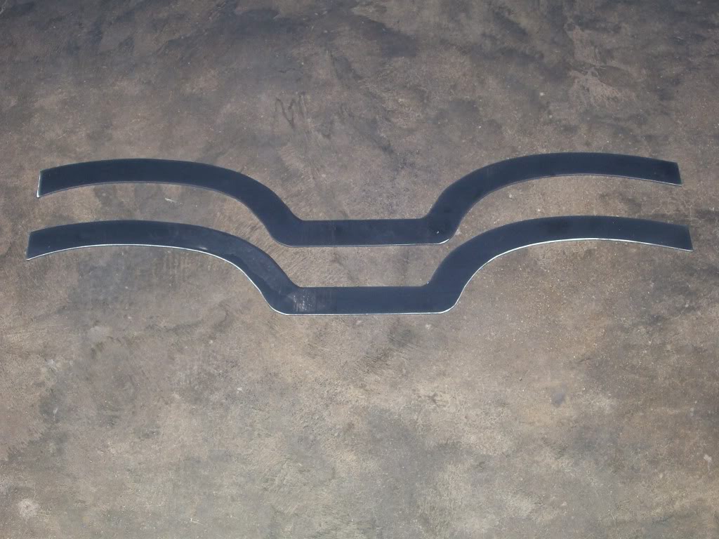
The tricky part here is getting the two lined up near perfect. If the two are not lined up properly, the whole thing is gonna be a twisted mess.
The square tubing between the plates is 1 1/2", I wanted the crossmember to be 1 3/4" wide when done. With the 1 1/2" spacer and the 1/8" side plates, I got my 1 3/4" width.
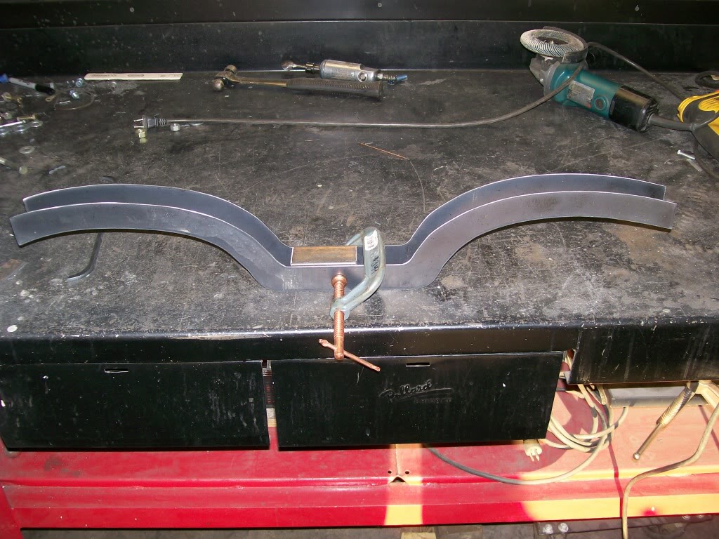
Back to using the press again, I slowly shaped the top and bottom plates to match the contour of the side plates.
In this picture the crossmember is upside down. Flipped over, you can imagine how the crossmember touches the frame on both outer ends, then raises up over the exhaust, then drops between the pipes to support the transmission in the center.