You must be logged in to rate content!
14 minute(s) of a 668 minute read
3-25-2012
Moving forward on the choke "pull off". The choke pull off is a vacuum diaphram that is hooked up to the choke linkage.
Imagine the choke plate fully closed at cold start, no air going through the carb.
Once the engine starts, it's gonna need some air to continue running or it will flood out, due to too much fuel vs air.
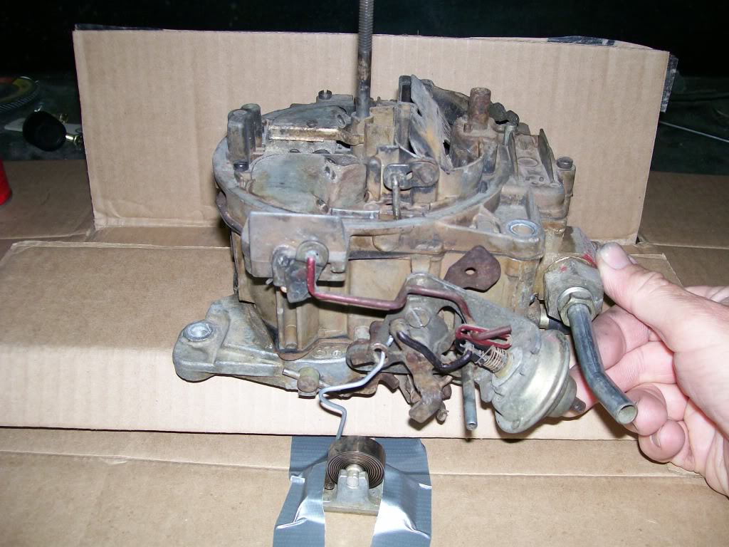
I don't have a vacuum pump or I would have used it to retract the vacuum diaphram arm. For demonstration I pushed the arm to retract it. Then used my finger to block the vacuum hose so I could get a picture of how it works with the linkage.
The vacuum diaphram (choke pull off) you see in the picture, has a vaccum line that goes to intake manifold vacuum. Immediatly as the engine starts, the choke pull off is gonna start to retract the arm comming out of it. It will retract to the point to where it makes contact with the black linkage connected to it in the slot. Once the slotted arm runs out of slot, it will pull on the black liknkage. The black linkage will now work against the spring pressure from the choke thermostat.
The end result is...the choke pull off will open the choke plate around a 1/4" of an inch so the engine can now get enough air to run til the choke thermostat gets warmed up enough to expand the windings. The choke thermostat will now hold the choke plate open from this point on. Til the engine gets cold again and it starts all over again.
Notice the black linkage also has a bend to it. This is also adjustable by either bending it more, or straightening it out. You can set how much air you need to get through the carb while on choke by adjusting the black linkage.
We still have the red linkage hooked to the choke pull off. It is playing a dual purpose. That'll be the next fosus.
On the other hand, the 57 is comming along, slowly, but it's getting there.
I mentioned using a dual electric fan assembly because it moved the fan motors away from the center. This next picture will show what I meant.
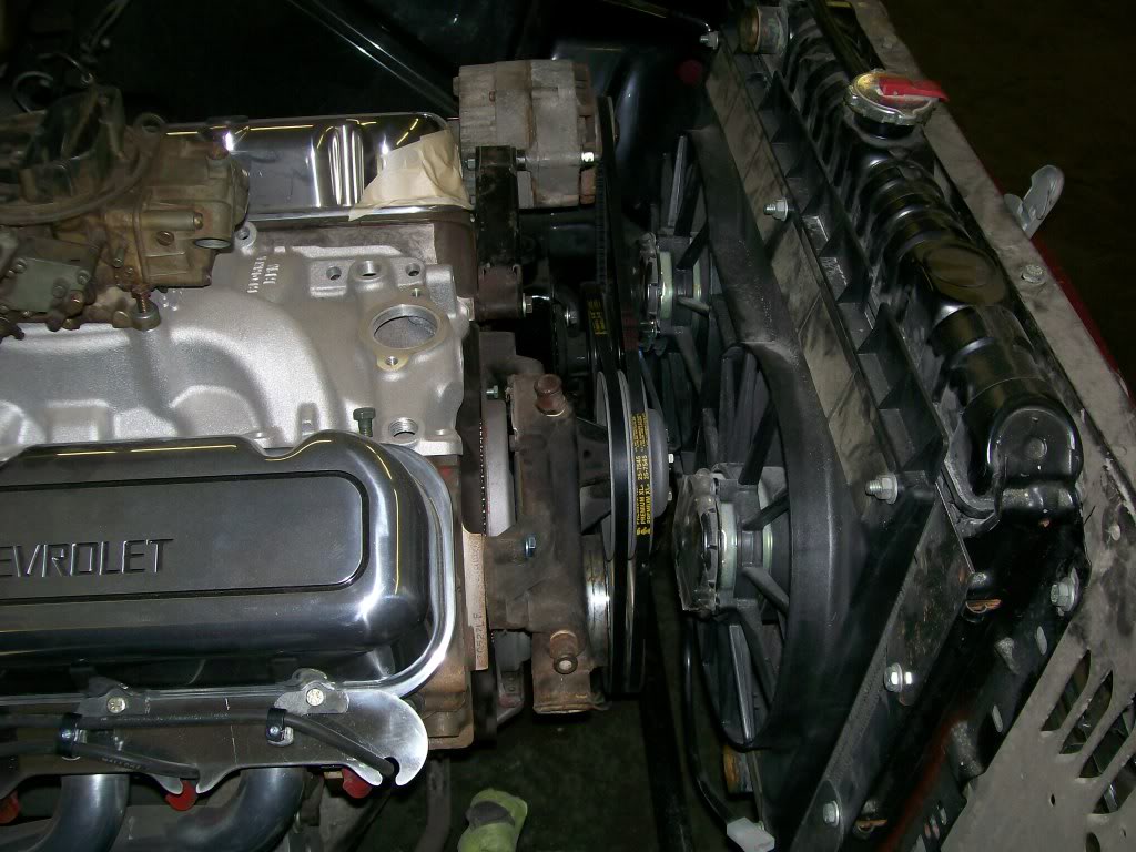
The water pump pulley has a pocket into now. Everything has fit just as I wanted. I have just enough room to work on everything.
3-26-2012
You have done well Scooter402.
The black round plastic cap on the side of many carbs is a choke thermostat. Very similar to the one I have pictured on this thread. The difference being it is mounted on the side of the carburetor.
With this design mounted on the carburetor, some of the linkage is eliminated. The design also cleans up the intake manifold by getting rid of something bolted to it.
The method of adjustment is as Scooter402 mentioned. By rotating the black plastic cap on it's mount, you can adjust how it reacts to different temperatures, just as the bent linkage was the way to adjust with the other design.
Many of the old black plastic cap designs had a metal 1/4" tube that went to an exhaust manifold to draw heat up to the black plastic cap. This heat is what caused the spring to expand and contract to open and close the choke plate.
Next is the black plastic cap that is seen more often these days. It has the expanding spring in the cap, yet along with the spring is a heating element. Very similar the the cigarette lighter, once 12 volts is provided, the heating element warms the spring, thus opening the choke plate.
This last design with the electric choke setup is the favored design. The whole thing is one contained unit, and very adjustable.
3-28-2012
Yes, mine is ot of a International scout. It's a dana 44 from a 1972 model. It does have drum brakes right now, but perhaps by the end of this year I will replace the drums with a disc brake kit. With the large diameter tire, a good brake system would be nice.
When we do the SOA (spring over axle) conversion, the main streering arm does become an issue, especially with the lift, we create quite an angle from the steering box to the steering knuckle on the passenger side. With this angle the bottom of the passenger side leaf spring wants to interfere with the steering arm passing underneath of it. ( I know you know this, but I always explain for those who have not encountered this problem yet.)
The steering arm (sometimes called a draglink) is a home fabricated and bent arm I made 27 years ago. Once I made it, I was curious of how strong it was so I tried to stress it in situations. I quickly learned it had more flex than I liked so that is the reason for the extra gusseting that is welded to the bent area.
If I redue this arm again, I will use the same idea. One thing I will do is bend a slight drop where it passes under the leaf spring, otherwise, the same basic shape with perhaps slighly different gusseting.
Now..... If I built a long travel/very flexing suspension system, I would go with a high steer and go over the leaf spring if possible. At the suspension flex I deal with right now, mine seems quite adequate.
As for driveability, this truck goes down the road very well. I just drove a 70 mile round trip on monday, I drove around 55 to 60 mph the whole way with no issues, no white knuckles, I'm very pleased with it's driveability.
The only time I notice the large tires is pushing on tight turns over 25 or 30 miles an hour. I have to realize the amount of rubber between the rim and the pavement, and the tires will flex when pushed into hard corners.
Hope this helps...
3-29-2012
CrawlerSaurus, there's a couple of technicalities I want to cover with your build. First I want to bring the carb conversation to a close.
I'm bringing a picture back that we've seen before. In the last conversation having to do with this picture I focused on how the vacuum pull off opened the choke plate slightly to allow enough air to keep the engine running when cold.
Then I mentioned the linkage that I marked with a red marker. This red linkage does not have anything to do with the choke. It actually has to do with the secondaries on the quadrajet.
Using the knowledge that we need to operate the opening of the secondaries by demand of the engine using the vacuum of the engine to define the demand.
I want to keep the explanation as simple as possible. The first point to make is... this carb uses vacuum to operate the secondaries, but it does it in an opposite way that the Holley does.

The picture for reference.

If we have a grasp how the vacuum above the throttle plates, differs from the vacuum under the throttle plates, we can understand the function.
Where the Holley used the vacuum to pull the secondaries open, the quadrajet uses the lack of vacuum to allow the secondaries to open.
The vacuum pull off you see is depressed at normal driving and idle. Since it gets it's vacuum below the throttle plates, when you open the accelerator, there is a drop in vacuum. This drop in vacuum causes the vacuum pull off to extend itself.
It extends itself slowly, this slow release allows the red linkage to move, this movement allows the large butterfly plate covering the opening to the secondaries to open.
There is more to be said about the quadrajet carb, if anyone is interested, let me know. Otherwise, I hope this tutorial on carbs has been helpful.
Once again, I tip my hat to the engineers who figured the idea of using one vacuum canister to perform two jobs.
In the shop I had an issue with a lawn mower, then my heart had an issue, (getting old sucks), nothing major... thank God.
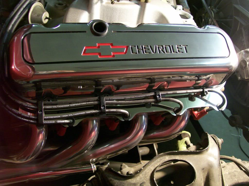
I finally finished the plug wire holders on the 57 Chevy. They turned out better than I hoped.
Very good questions, I know there are alot of pages to this thread, but I want to have you go back to page 41ish. I posted the work done to get the spring over axle change on this truck.
Yes, by using the original springs I was able to center the axle. The scout used a wider leaf spring, but with the grinding and fitting, the perch you make will fit the Willys narrower leaf. I had to set the passenger side leaf close to the front differential. In the pictures I show how I did the grinding and made the perches that I welded to the axle to support the leaf spring. The drivers side was easier, I just had to match the height of the passenger side, and check to be sure it was centered where I needed it to be.
The springs I used is a 10 leaf pack for the truck, I added a leaf to achieve the exact ride height I was looking for.
Ok, now the technical. To get the pinion angle and tipping the axle forward to get the space needed to get the draglink we talked about yesterday to fit with clearance, you lose some of the camber that is desired. Follow the build around page 42 and 45ish, there was a good conversation covering the need for proper camber.
My camber is not textbook perfect, but I have used this truck for 27 years now without any issues. As I mentioned, it rolls at 60 mph very confidently.
Hmmmm.... Missouri to Australia, how cool is this. Good luck.
4-5-2012
Wow, 9 months is right, time does fly. Sitting back in my chair, rubbing my chin, hmmmmm. we've covered alot of stuff too.
Still working on the 57 Chevy truck, I've made some progress.
One item that my dad wanted on this truck is what's called "exhaust cut outs". Personally, I never considered them, but I believe they were a big thing many years ago.
Exhaust cut outs are a "y" shaped pipe addition that is between the engine and mufflers. One of the outlets on the "y" goes to the muffler, the other outlet has a flange welded to it. There would be a cap bolted to the flange. Once you get to the race track, unbolt the cap and you have an open exhaust system.
I've decided to follow through on his idea and add 2 exhaust cut outs. Of course, I have to complicate the system and add a few things to enhance the finished project.

First, there are three choices of how to open the cut out. First is as I mentioned, unbolt the cap and remove it. Second, they make a cable operated valve inside a "y". Third, an electric motor unit that operates a valve assembly that bolts to the flange on the "y" pipe.
I'm planning on making my own "y" pipe, and using the electric motor valve.
Next, I will have four out lets all together. Two will be the tail pipes after the mufflers. Two will be for the straight pipes that will exit just in front of the rear wheels.
Now for personal preference.... I'm not too big on having two tailpipes pointing in different directions, say..... like the exhaust outlets just infront of the rear wheels.
Here, let me explain.... If I have an 8 cylinder, I basically have two, 4 cylinder exhaust systems. If they both exit near each other, the vehicle sounds like an 8 cylinder, the pulses mix together.
With the two tailpipes exiting on opposite sides of the vehicle, I don't get the blend of all 8 cylinders, it sounds like two 4 cylinders. The pulses don't mix together.
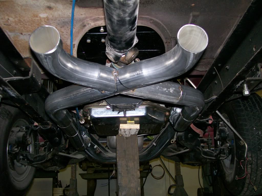
This is the reason for the extra work I'm doing, I will build an "x" pipe to blend the two banks of cylinders together. Hopefully now when I open the exhaust cut outs to open pipes, I will have the sound of all 8 cylinders coming out both sides of the truck.
Now for a picture of what's going on. I myself do not have an exhaust pipe bender. I basically form an idea and have a local shop bend some pipe. Then I get to cutting, grinding, and welding.
If I was doing a simple dual exhaust sytem, this would be a breeze. Ha, I just can't keep it simple.
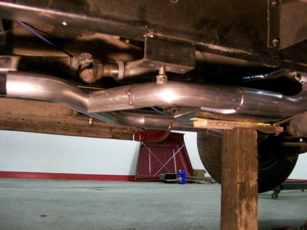
With this next picture the system is coming together. I have all 8 cylinders mixing in the "x". I have a little finalizing to do on these pipes, but I have the fit I'm looking for.
After this point I have to figure for the "y" pipe that will send the exhaust to the sides. After the "y" I just have to install mufflers and tailpipes to the rear bumper area.