You must be logged in to rate content!
6 minute(s) of a 891 minute read
6-4-2018
Made really good progress on the exhaust this weekend. Friday night I started making the 3.5" oval S bends based off of a CAD drawing I made to figure out the lengths/angles required to achieve the overall length and offset that I measured needing out of the bend...
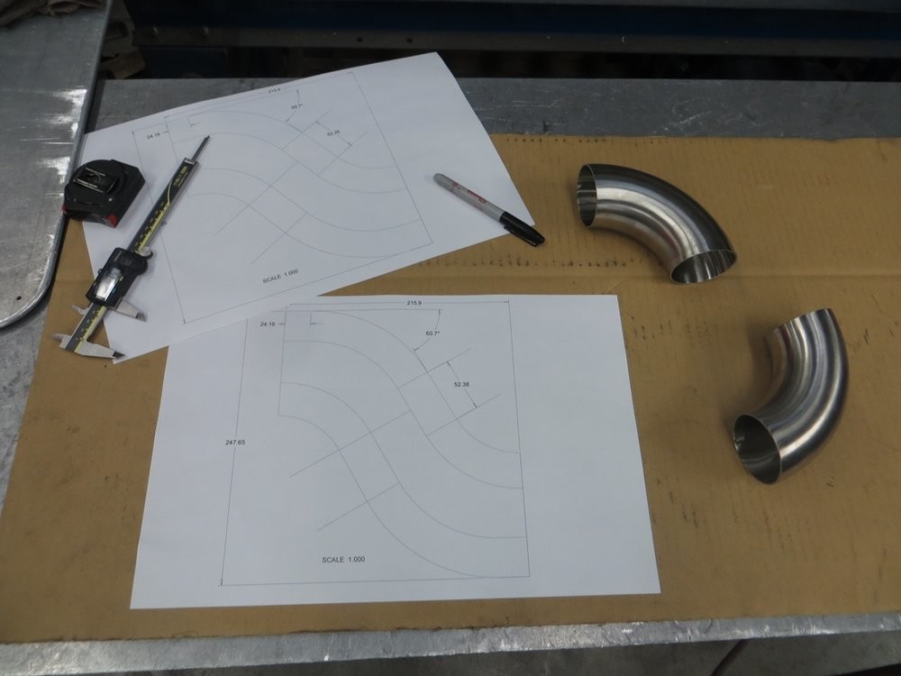
First step was to split the 90* bends down the bend centerline, to create inside and outside bends. I did this by clamping the bend horizontally on the table, and using a jigsaw (with a trimmed blade to not bottom out on the inside of the tube), and a lot of patience...
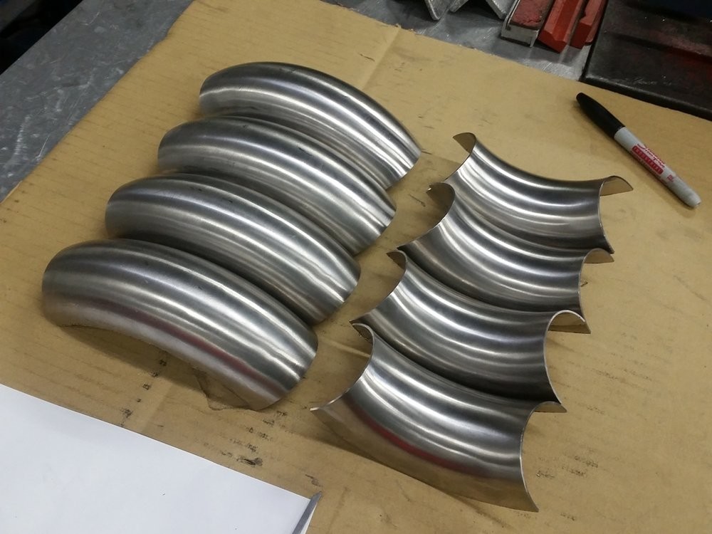
Once I trimmed the first bisected bend to the correct angle, I used that cutoff bit to be the guide for scribing a line on the remaining bends to follow on the bandsaw...
First angle-cut pair of inside & outside bends...
Center straight filler tube...
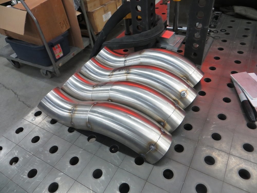
The four outside bend sub-weldments which will make up the two S bends...
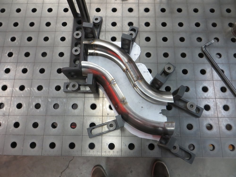
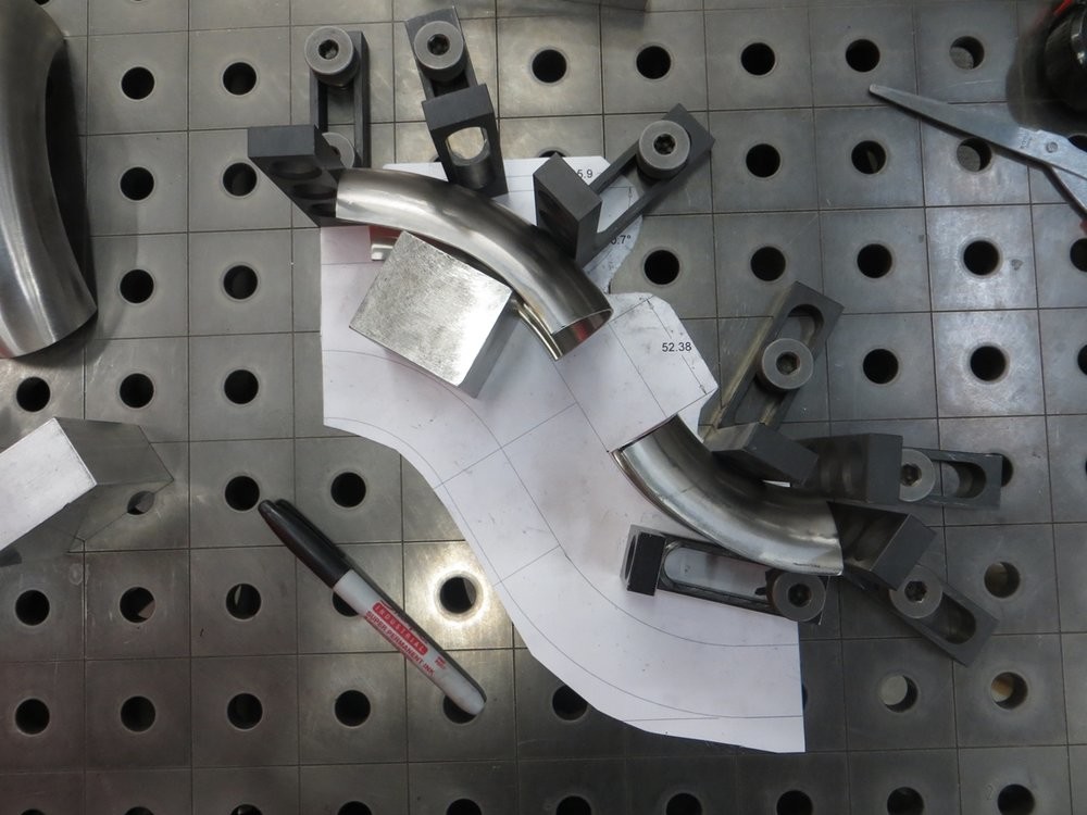
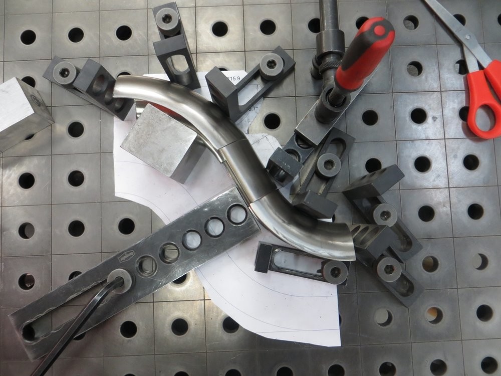
Using the drawing I created, cut out a paper template and trimmed to fit the actual as-cut tube shapes...
Template then transferred to 16ga 304SS...
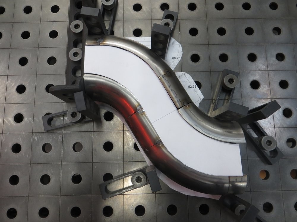
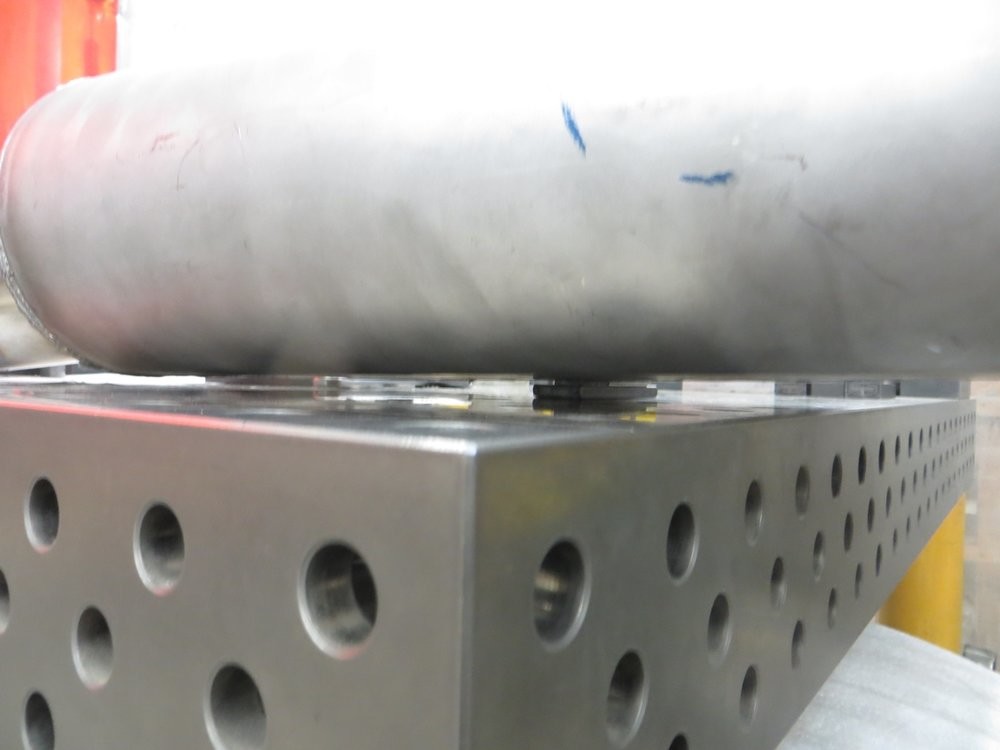
The fixturing table was SUPER helpful making sure that everything was flat and the underside of all the pip sections is flush on the underside.
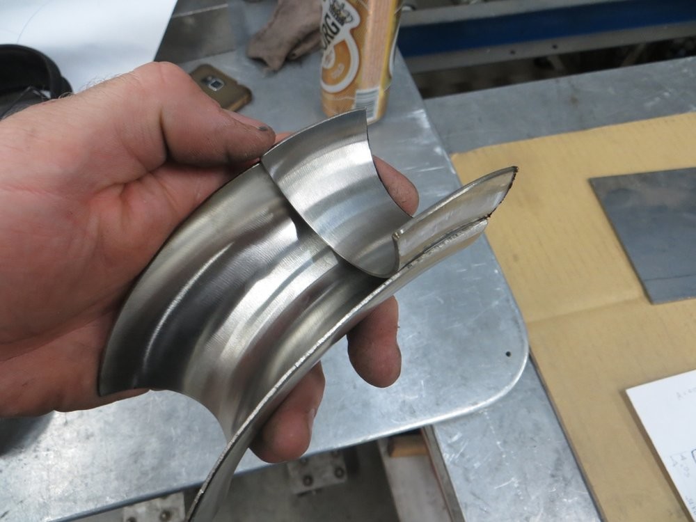
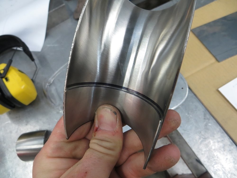
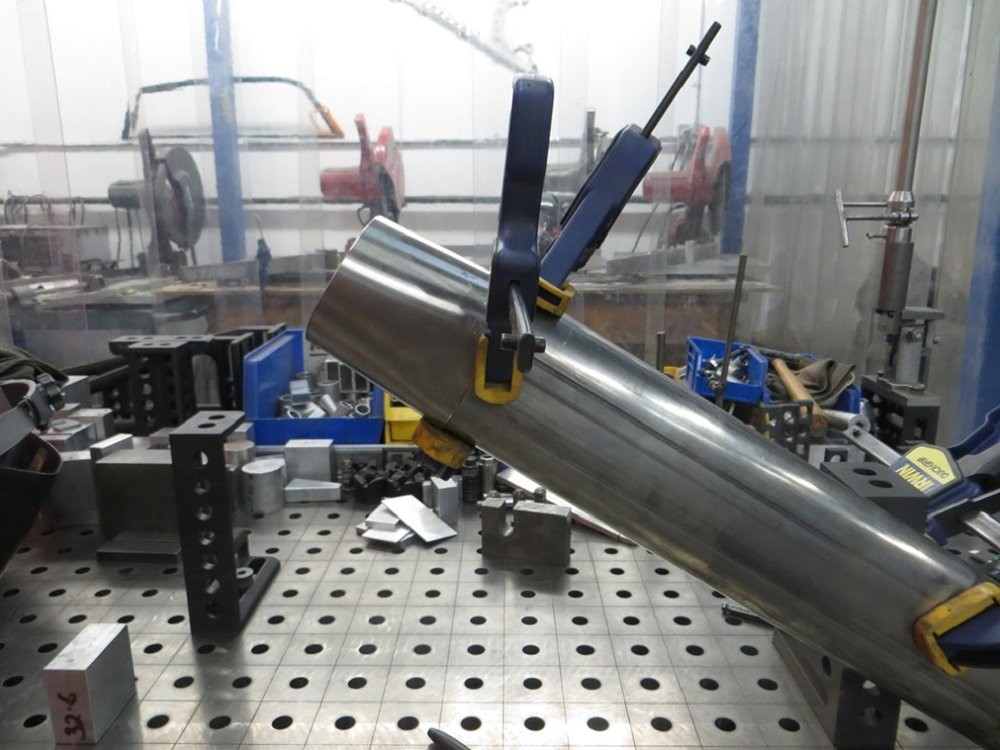
Here is the uncut S bend being aligned to the Vibrant oval tube...
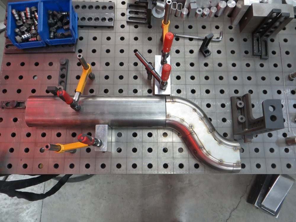
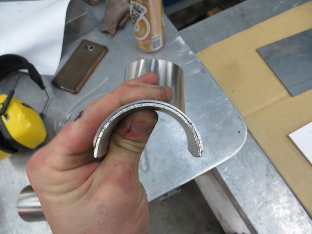
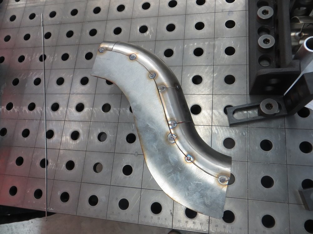
After a little grinding, both ends of the S bend are flat and ready to butt up against tubing for welding...
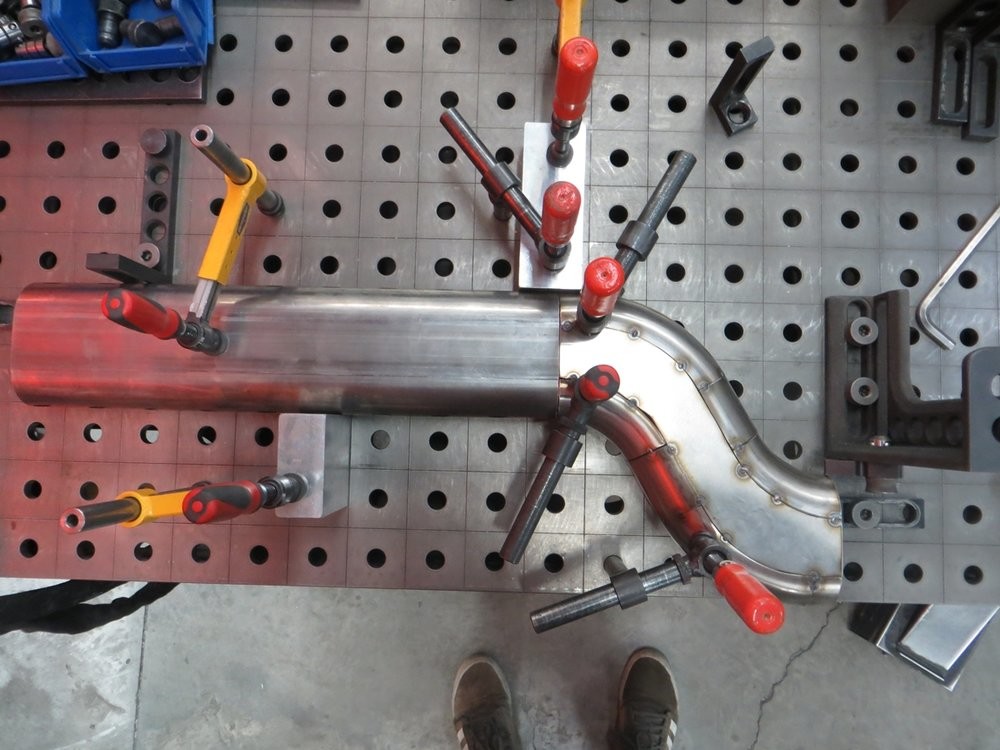
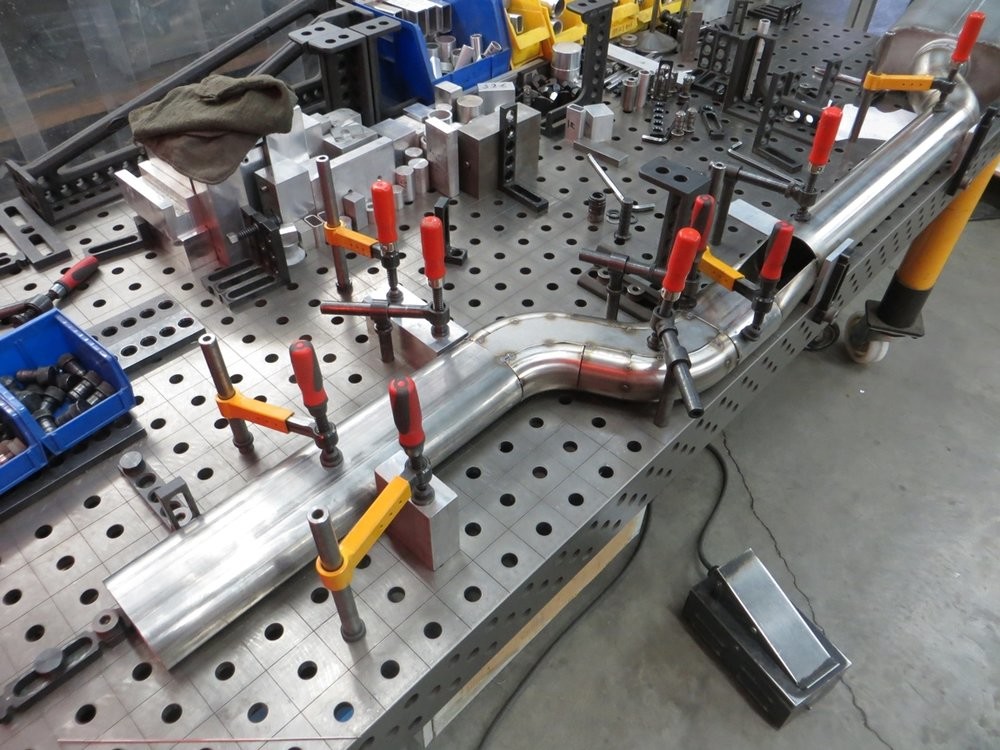
Flip the weldment over to fit the underside with some tack welds...
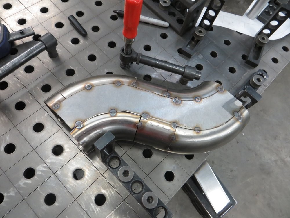
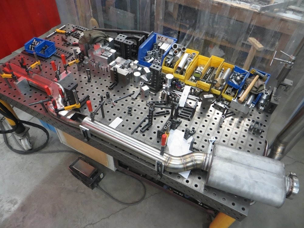
Aligning with the rest of the tubing (passenger side)...
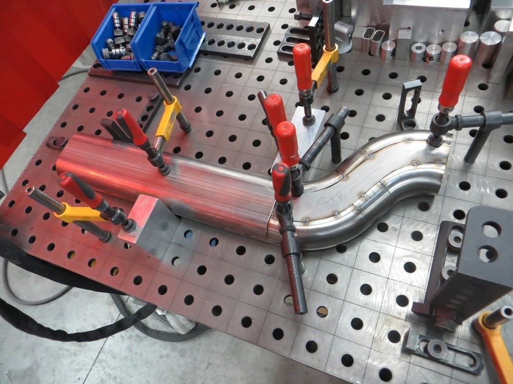
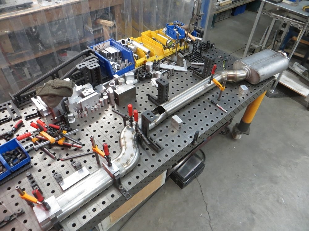
Shimming the muffler up, they have a slight upsweep.. not intentional but okay.. important thing is that the tubing itself from oval to round is all in plane...
Passenger side...
Driver side...
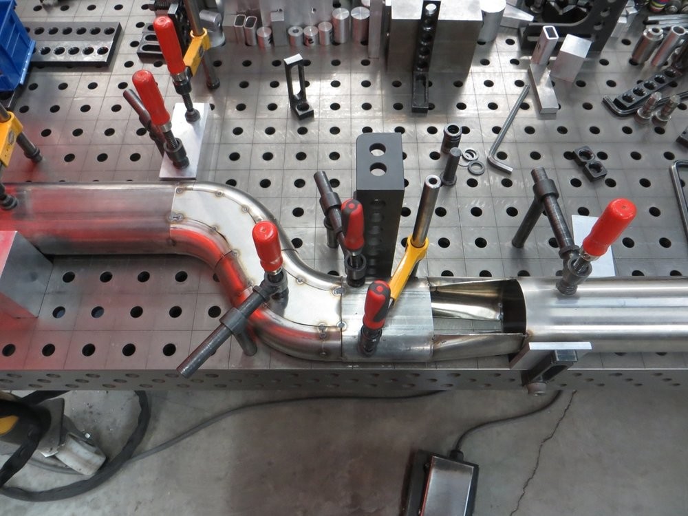
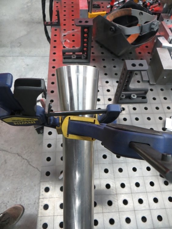
After previously fabricating the oval-to-round transitions, I decided to try just squishing some 3.5" round for the transition from oval back to round at the firewall. It was tough and required a lot of fine-tuning with the vice and a BFH, but it turned out well enough...
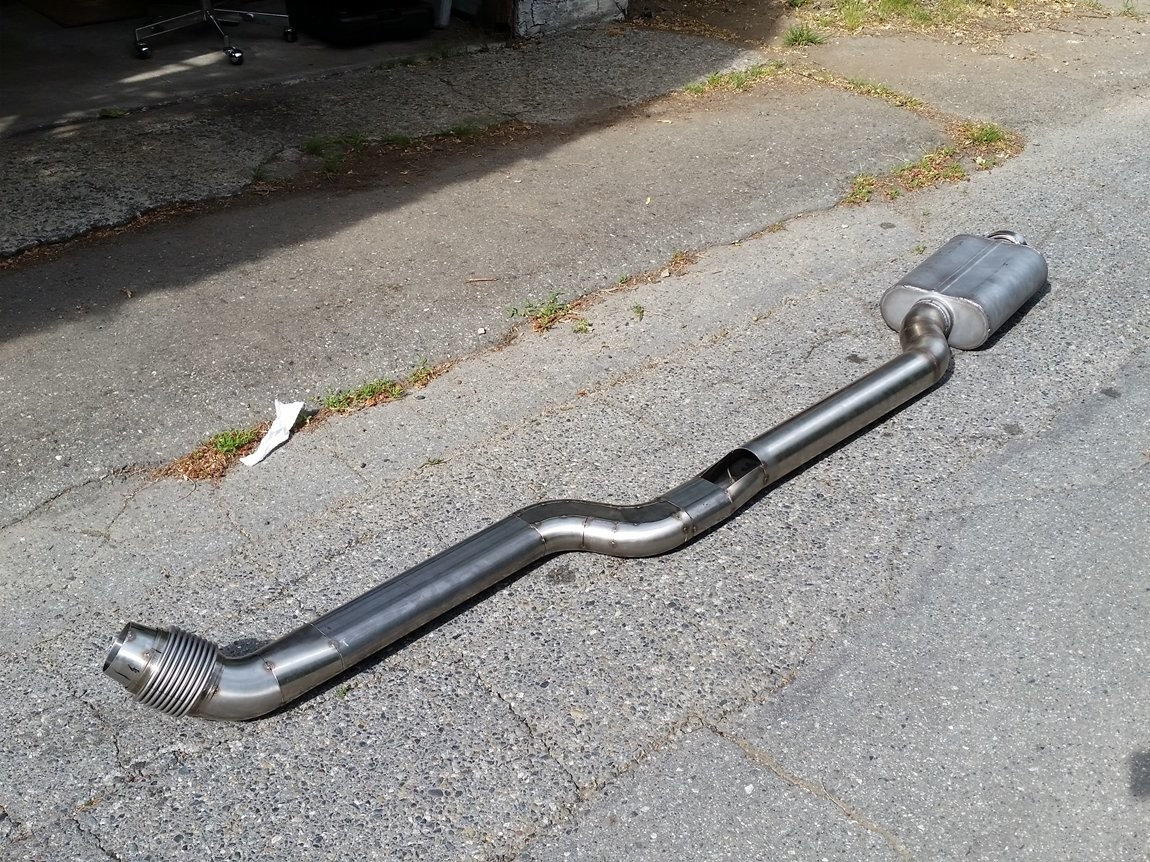
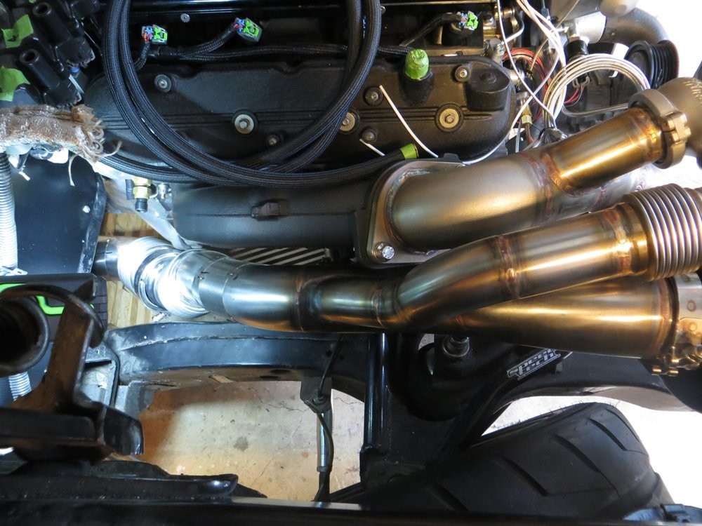
Here's what the passenger side looks like in daylight, minus the 3" v-band flange which I welded to the 3.0"-3.5" reducer taper after this pic.
Here's the passenger downpipe tacked together. The idea I was going for is to have lots of the vibration isolation between the downpipes and the under-floor exhaust tubing, located in the firewall area.
The piping goes like this:
Turbo turbine housing -> 3.0" downpipe (~24") -> 3.0" flex bellow -> 3.0" v-band -> 3.0"-to-3.5" taper -> 3.5" flex bellow -> 3.5" bend -> firewall -> 3.5" round-to-oval -> etc etc
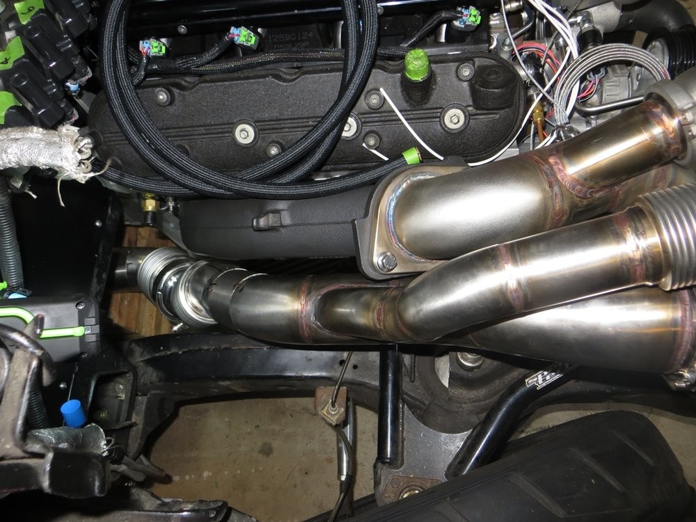
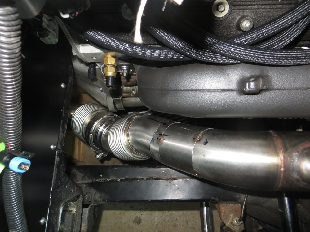
There is REALLY good flex between the two bellows.. I can misalign the piping maybe 5 degrees, and very easily too. So I will be using stiff rubber hangers to semi-rigidly secure/bolt the exhaust tubing to the car, from the firewall-rearwards.. I'll show that progress in an update very soon.
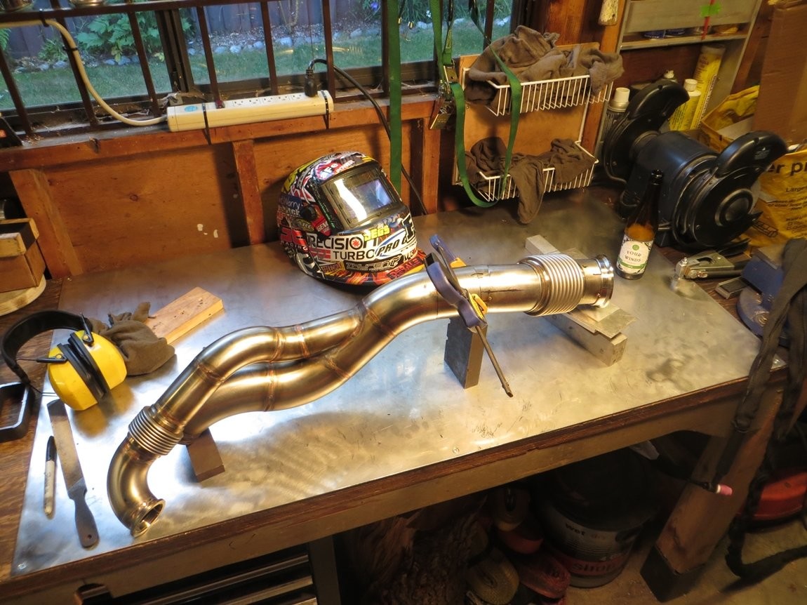
These pictures are very deceiving.. it looks like the bottom 3.5" bellow is super close to the bellhousing starter hump, but it actually has 3/8" clearance; it looks super close because the bellhousing hump is closest to the exhaust between the v-band and the bellow, which isn't very visible from any camera direction. Also looks like the top 3.0" bellow is super close to the subframe rail, but it has over 1/2" clearance..

Wow thanks for sharing!
Posted by Diggymart on 3/3/19 @ 12:40:25 AM