You must be logged in to rate content!
7 minute(s) of a 891 minute read
1-4-2017
That boost-rpm graph is a reverse-engineered plot out of curiousity of what the compressor side wants the boost to be for a 408 in a most-efficient world.. it's not saying that the turbo won't spool quicker or reach full boostearlier, just that for that engine, for the turbo's to spool quicker would mean operating above/left of the efficiency islands.
Also you have PT6262's which are much closer to a Garrett GT3076 which has a similar compressor map but the island is shifted about 10lbs/min to the left, so for same boost pressure ratio, that boost is produced more efficiently at a lower rpm.
I'll update my turbo graphs on my home computer with a couple different scenarios and post those. I've been on Maui for a week.. which is perfect research time. I've gone thru multiple iterations of my engine rotating assembly, cold side, hotside, cooling, transmission, exhaust system, you name it. I've decided:
1) keep existing 6L iron block.. it's strong, everything bolts up.. money in the bank.
2) stroke engine to 4" but keep cylinder thickness reasonable. Maybe bore to 4.010" but try to just hone existing 4.005" if possible.. enlarge bore to 4.030" as last resort
3) keep single turbo setup for now, even tho PT7675 will be bit undersized for stroker.. more on that in a bit
4) rework one turbo hotpipe to allow thicker rad/fan stack in front of accessory drive.. this is a must address issue. Can't move intercooler forward so more clearance needs to be developed between current fans and passenger hot pipe. Also need to reroute waterpump inlet routing for more room.
5) new dual exhaust. Keep current 4" downpipe, rework the merge so instead of splitting into dual 2.5" it splits to dual 3.5" oval (2.5"x6" so it's equivalent to 3.5" round exhaust), routed up to transmission tailhousing area. Make new "3.5in oval" stainless exhaust from tailhousing back to dual 3.5" Dynomax mufflers under floor pan, then goes underneath the axle and straight back under the gas tank (heat tape and heat shields used) exiting straight back underneath rear bumper. Obnoxious, but easiest to route.
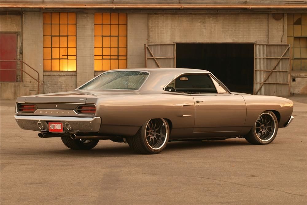
I've always liked the brashness of the layout of the 1970 Roadrunner "Hammer" exhaust (except for the refined nature of the rounded & polished oval tips) but with straight cut round stainless tubes instead, maybe painted flat black for more brutal/purposeful appearance..
After much thought, the future setup (which I'll be keeping a constant eye out from now on for discounted parts) is.. CTS-V manifolds welded to short schedule 80 elbows feeding 64/65 or 66/67 twins, Precision 46 wastegates and 3.5" downpipes that then meet up with the new oval 2.5"x6" pipes under the floorpan.
It's good to have a goal that I can constantly think on and tweak as I see deals and classified ads for things, and not make any impulse buys right now before I tackle other more urgent issues. The layout in my head should require zero "undoing" of work I plan to do this spring when the garage concrete heats up.. damn you Mark and your 2 post lift! 
Clint, it's too true.. but you gotta pay to play and sometimes you just get bitten I guess.
Mark, the cam bearings were new and installed by High Performance at the time the block has bored and honed to 4.005", decked 0.004", the main and cam bearing bore alignment was confirmed good and block cleaned. However I ran the rebuilt engine with the stock truck camshaft for a summer before replacing with a Tick turbo grind Comp cam similar to yours. I plasti-gauge'd the bearings and I recall them being on the looser side of the spec range but still within range, however I never recorded the values so can't look back on it. I'm chalking it up to warm oil and maybe strangely worn cam bearings. I'd like to be the one to rebuild again, but I've also contemplated having High Performance throw together the short block just for piece of mind on my end.. although I'd really like to just do it myself again.
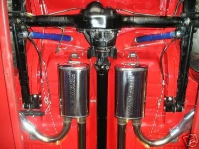
Why don't you like the under-axle routing, other than it hanging visibly low from the rear as well as heat? To the best of my memory, with my ride height the bottom of the axle is near or above the centerline of the muffleroutlet. The coilover upper shock mount crossbrace is right in the way, and the next tightest fit is between the upper control arm axle-side mounts and the OD of the coils.. it's effing tight in there even for 2.5" exhaust.. the shock mounts and cross brace would have to go up probably 2 more inches into the the trunk to be safe, and the shocks would need to move more vertical, but there's little room there until they hit the insides of the framerails.
For side exit exhaust, either under the rocker panels or thru rocker panels, there'd need to be some serious routing trickery to get around the front leaf spring perch as that's what my lower control arms mount to, and I need to put the mufflers in the stock floorpan recess location.. so some Z-shaped tailpipes for sure. Also don't like the same side in-out mufflers as that's not very straight-thru!
It'll be an other 3-4 months before I touch that, so plenty of time to discuss. The only option that's firmly off the table is turndowns after the mufflerbefore the axle, as it's just too annoying.
Kindof relevant to the exhaust tubing discussion, but more particular to the turbo hotside piping, I plan to keep the internal cross-sectional areas as consistent as possible, as every time the turbo exhaust is allowed to expand or contract via the internal area changing, then it has to slow down or speed up accordingly and that means losing exhaust energy. Also the plan is to make the distance between exhaust manifolds and turbine inlet as short as possible. This means a spreadsheet that tracks exhaust volume and cross-sectional areas to make sure it doesn't neck down between the head's exhaust port, manifold's collector, hotside piping, T3 turbo flange, then turbine inlet itself. So far using 2.0" schedule 40 piping (2.067" ID, 3.355 square inch area) matches exactly with a T3 turbo flange (3.356 square inch area). Once I acquire and measure CTS-V manifold primary and collector areas, I could adjust piping ID to gradually neck down to the T3 area. so that the exhaust velocity stays as consistent as possible, with a small increase in velocity only as it enters the turbine.
There's a very interesting (and long) discussion on turbo hotside piping ID vs flow and hp capabilities in this thread:
https://ls1tech.com/forums/forced-in...over-pipe.html
So same idea goes for the exhaust tubing.. no matter the turbos I end up going with for a twin setup, they'll have a 3" turbine outlet size which I'll smoothly but quickly expand to 3.5" downpipes, and would ideally keep that exact same equivalent 3.5" internal area for the entire length of the exhaust.. with as few bends as possible.

Wow thanks for sharing!
Posted by Diggymart on 3/3/19 @ 12:40:25 AM