You must be logged in to rate content!
87 minute(s) of a 891 minute read
11-9-2011
A friend has been harassing me for updates so here goes, hope this is satisfying enough...
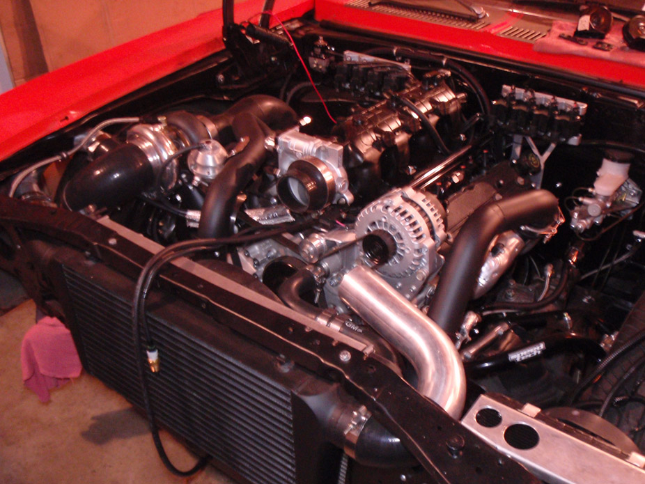
Got a Greddy Profec II B electronic boost controller so spent some time figuring all the vacuum/boost lines and careful/hidden routing...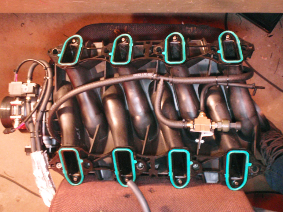
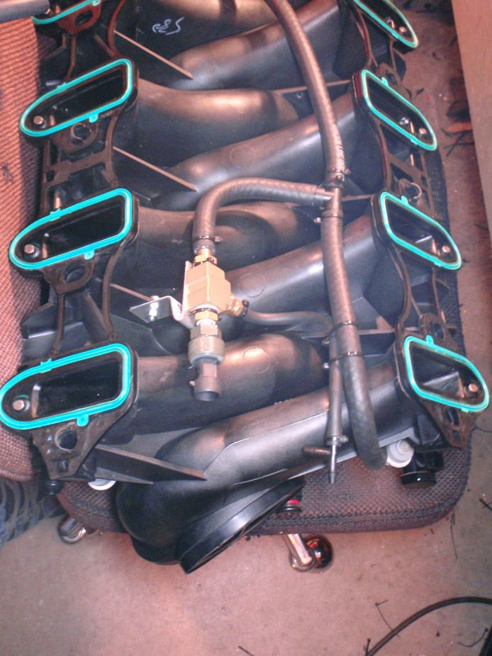
Sneaky little guy is just hiding under there...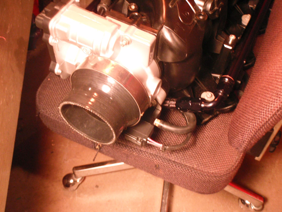
Finalized prettymuch ALL wiring 'cept the tail lights on this damn car, now time to put it all back together...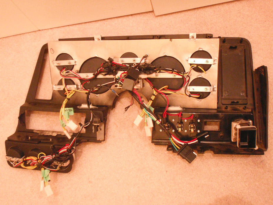
Looks scary at first. Took me a while to build up the ***** to drill these two 2" holes in the firewall...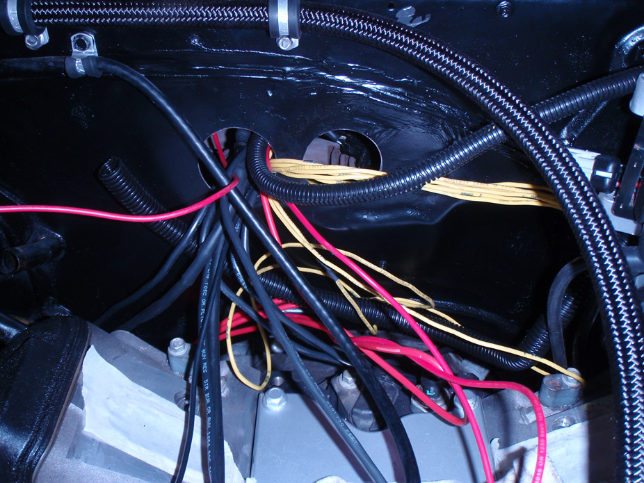
Relocated the fusebox completely inside the cabin of the car so only the lights/start solenoid/BAT+ wires have to pass thru the firewall...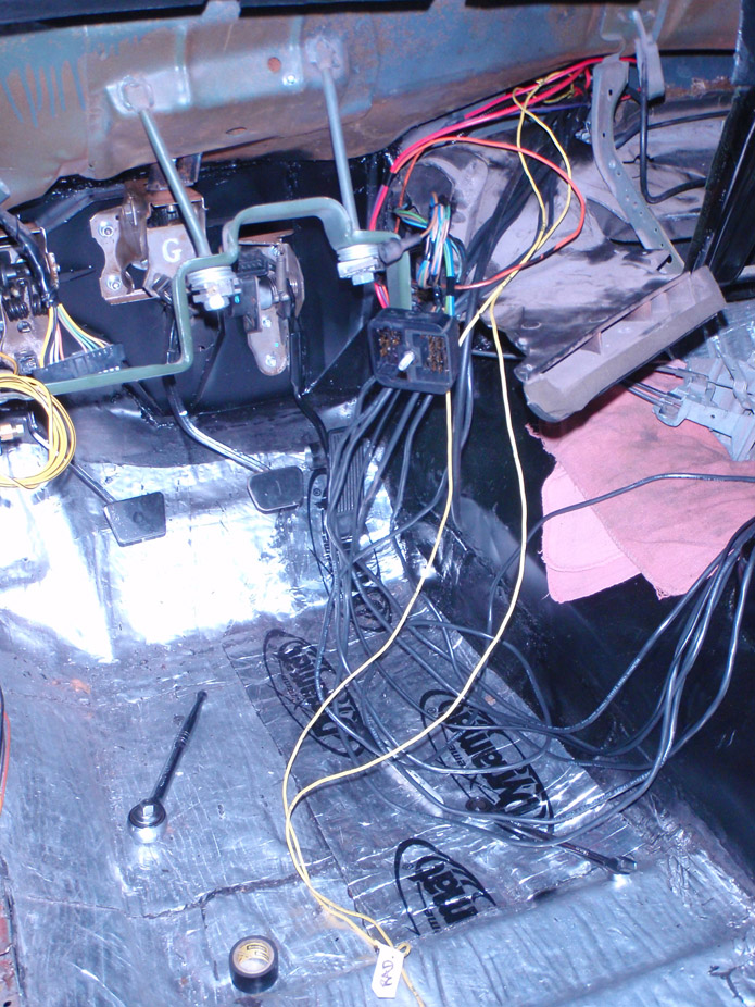
Stuff for the 3 O2 sensors...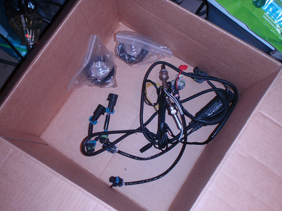
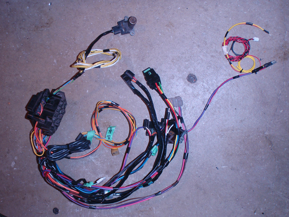
Modified, extended (for some sensors) & cleaned up Speartech Harness...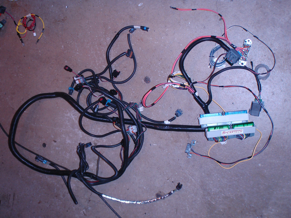
The end result of all wires passing thru the firewall, still needs a bit of finishing organizational work..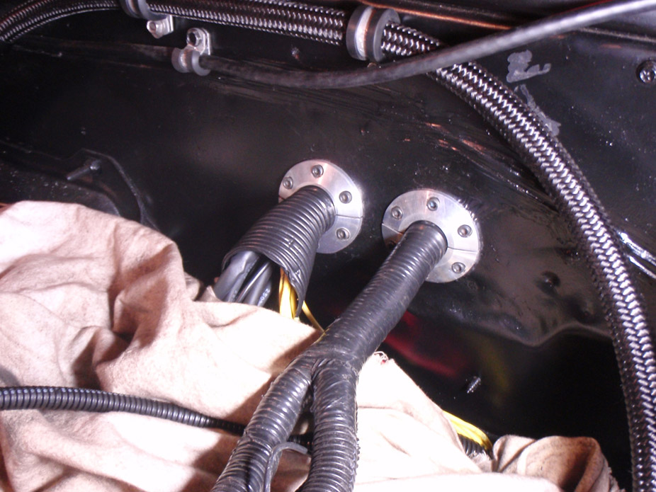
11-18-2011
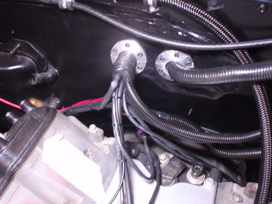
Late night beery wiring...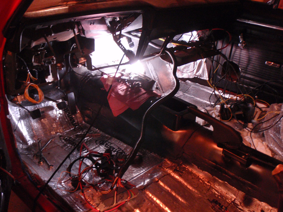
TAC module stacked on ECM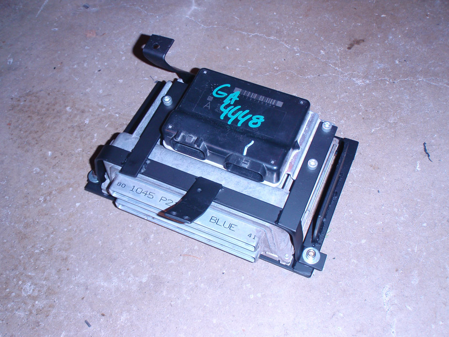
I originally had the ECM mounted right were the glovebox should be (was lazy and made it easy to bolt in) spent some more time and tried to tuck it away as much as possible. Fits directly behind/above the ashtray...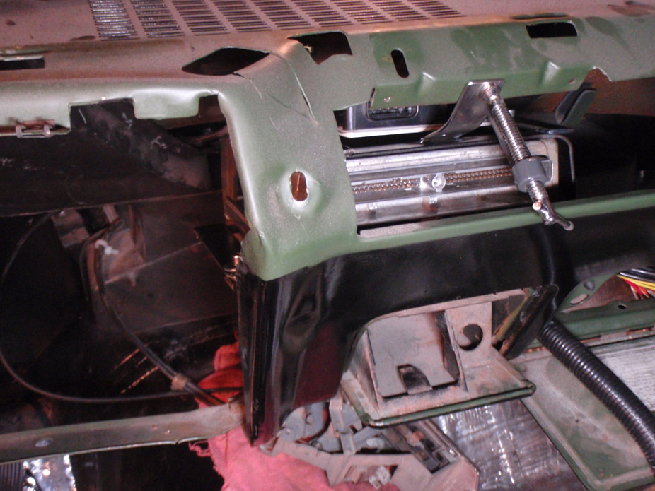
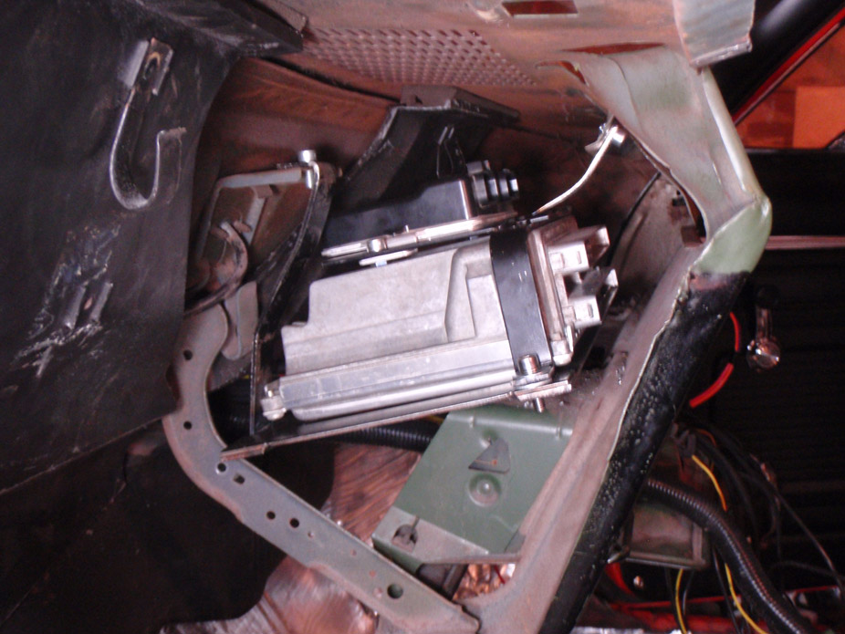
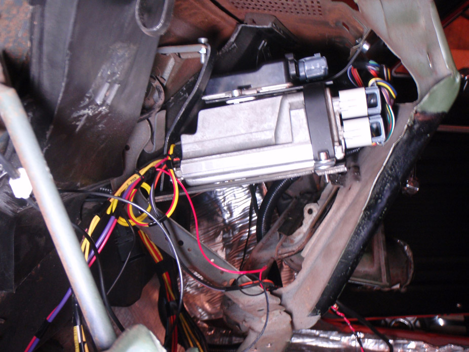
Guess I'll suck up the labour and sand down & paint the metal dash, guess it's obvious what the original color was... and how lazy the previous owner was... and their lack of care (spotty black paint and lots of runs). Oh well here is the ECM tucked away...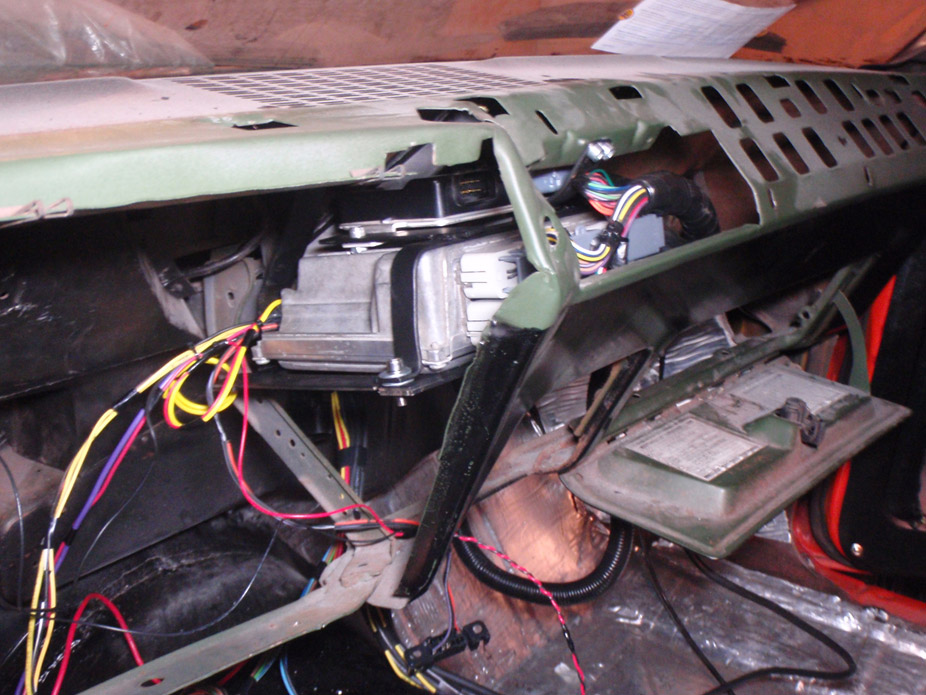
11-23-2011
All engine and body harness wiring is in and hooked up, going to sand and paint the metal dash tonight then the gauge panel, steering column, seats, etc can all go in for good.
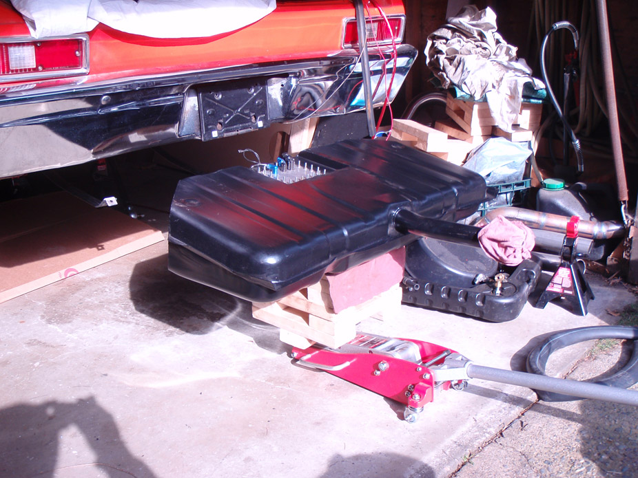
I've been guaranteed that the 4link will be ready for me to pick up on Monday, so once that is installed I can run the fuel lines and put the gas tank in for good, and hopefully fire it up!
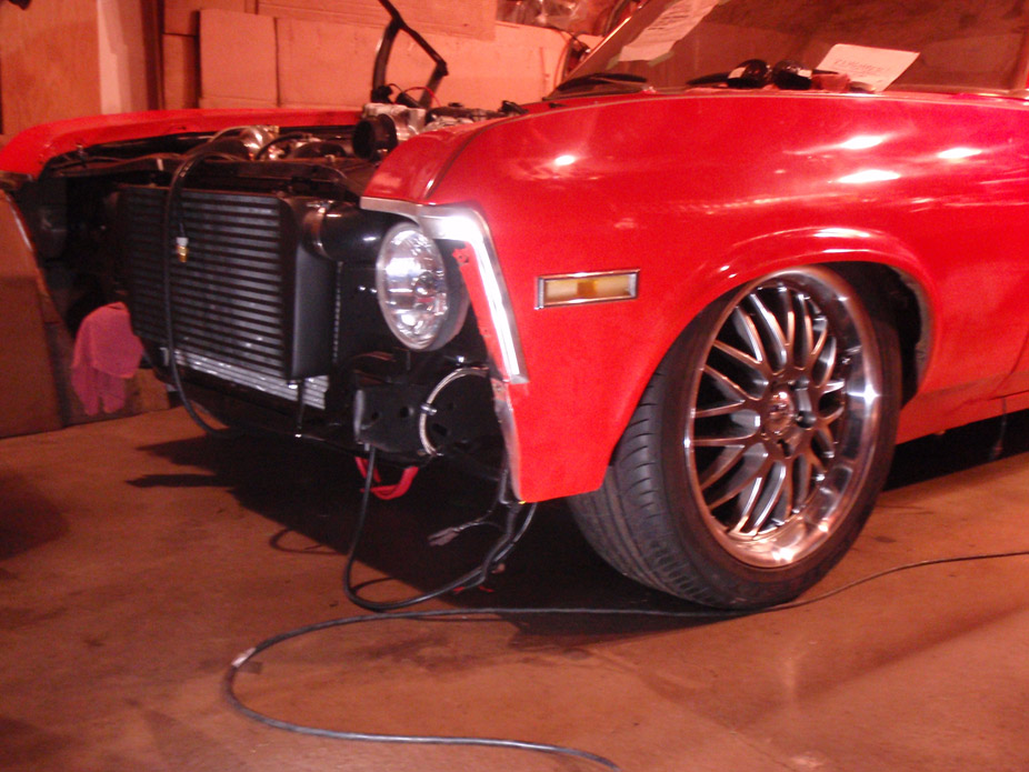
All that's left to do before the engine can be fired is a bracket to hold the oil cooler to the rad support, behind the driver-side headlight, and then run the oil lines. As well as finish bending the fuel hardline to the tank. And of course fill it with coolant and oil!
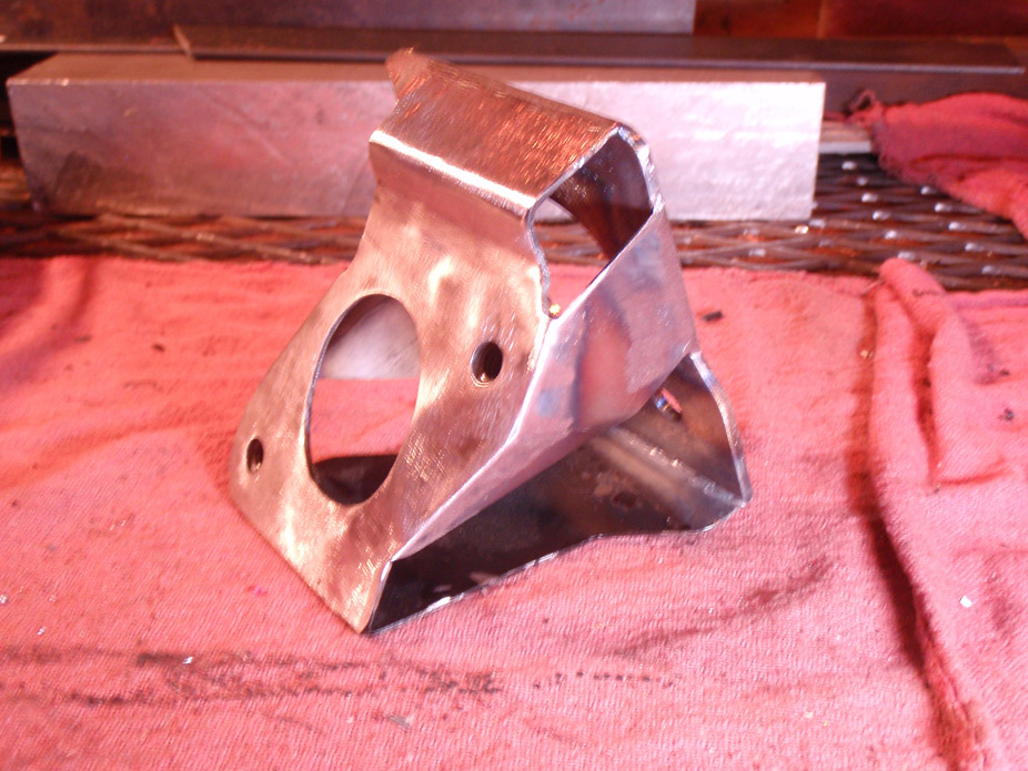
Turns out the original clutch master bracket I made was flexing a bit under full pedal depression, so I cut the backing plate off it, welded on a new 1/8"-thick backing plate, and then some sheetmetal supports. Shouldn't flex at all now. Like prettymuch everything I've made on this car, it just ends up getting modified or re-done better. Such is the process of learning!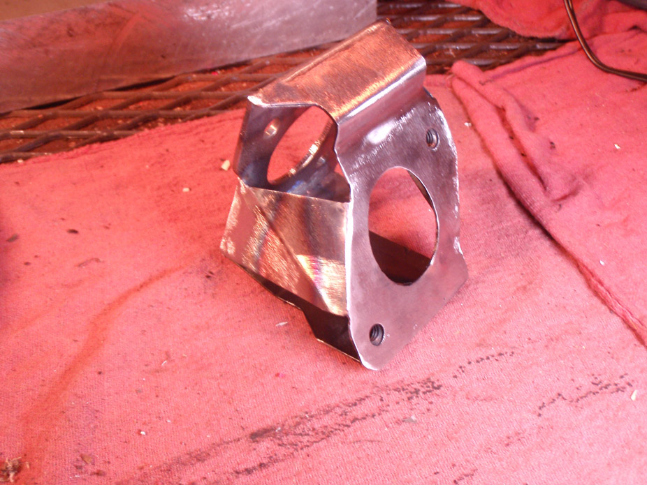
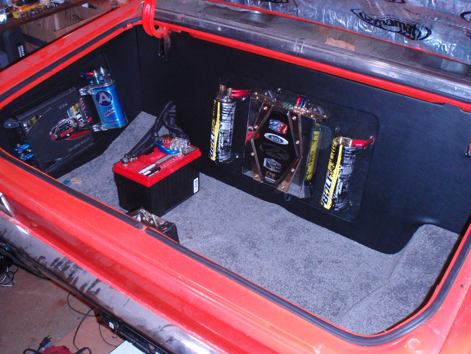
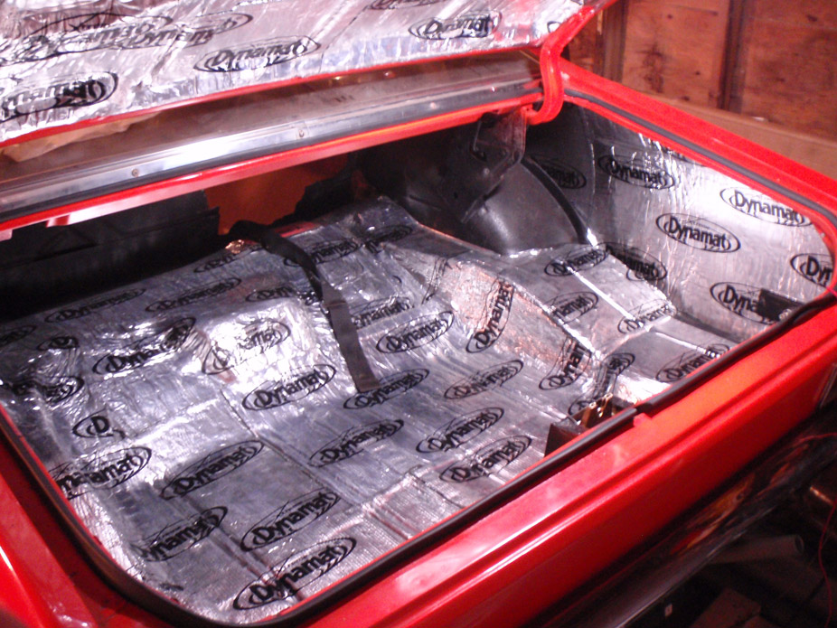
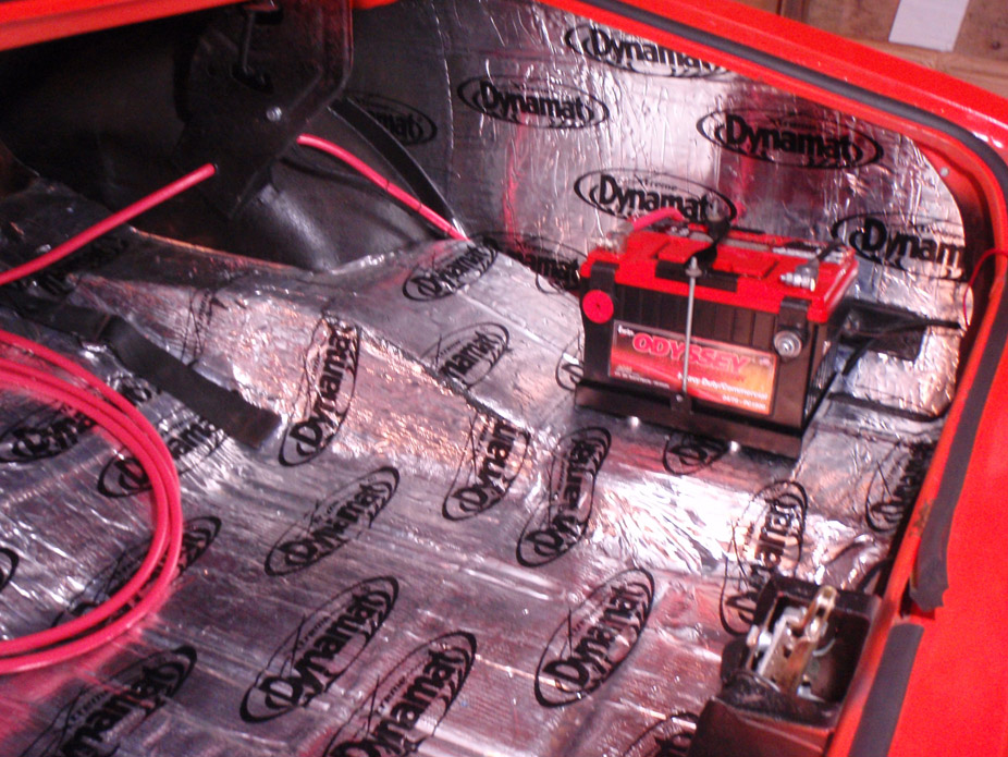
On the last legs of finishing up the wiring for the car, last part is the battery and getting rid of all the sound system ****... popped the trunk for the first time since mid-2008!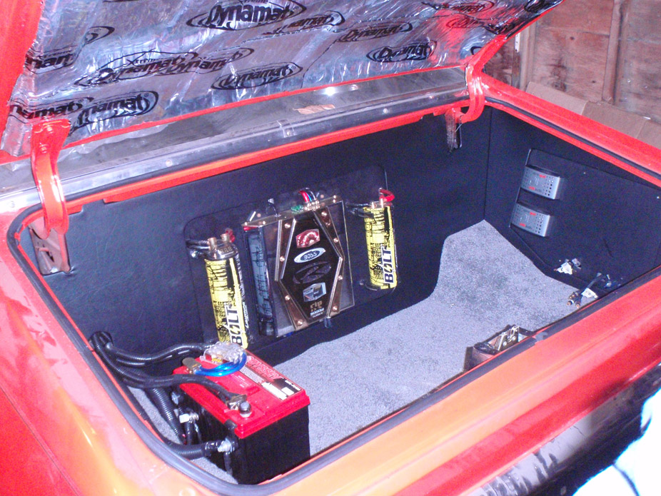
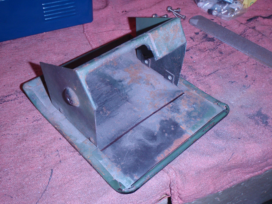
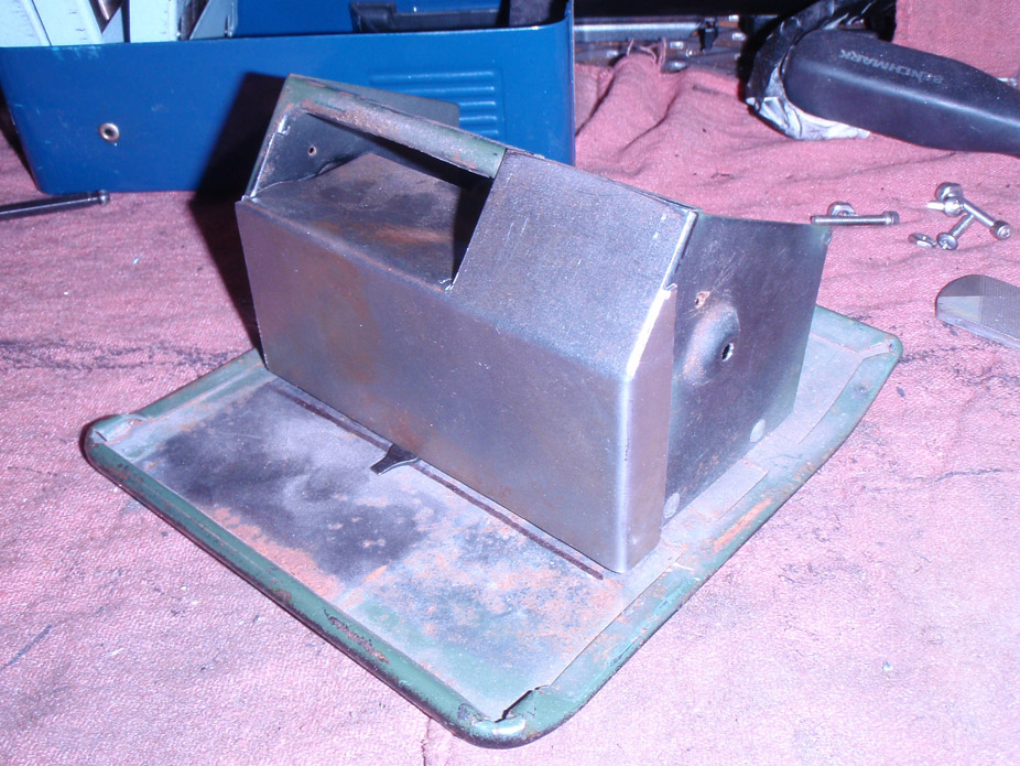
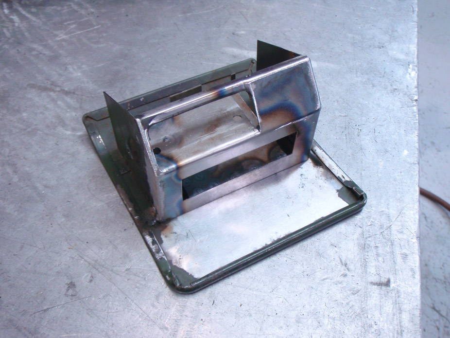
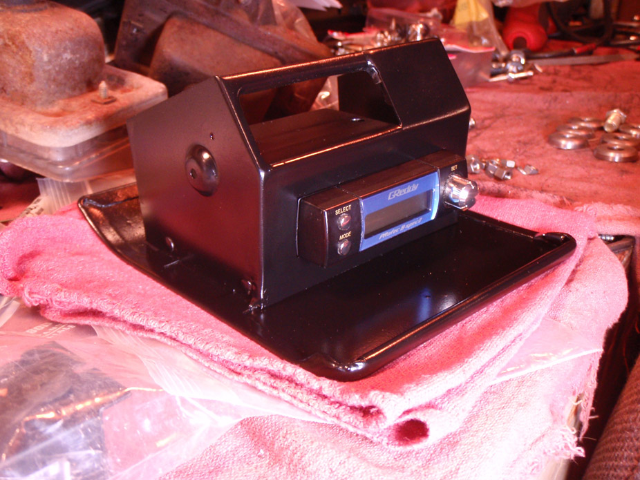
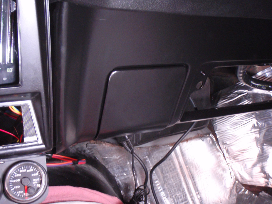
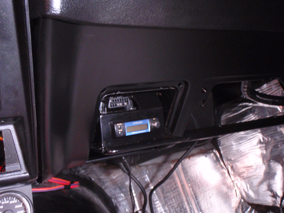
Was too lazy to start ripping into that crap so decided to make a stealth boost controller thingy out of the ashtray...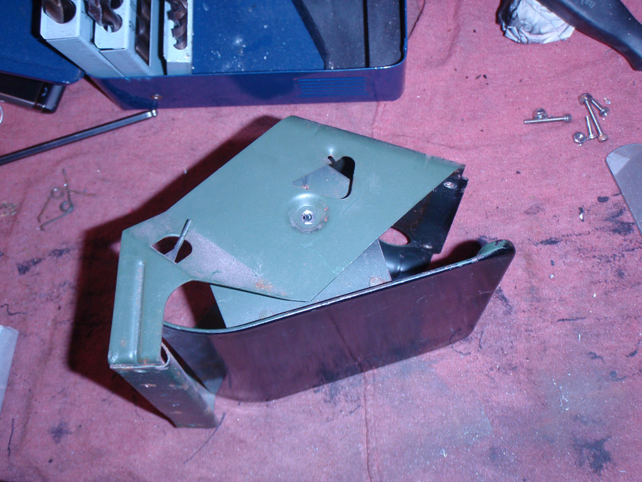
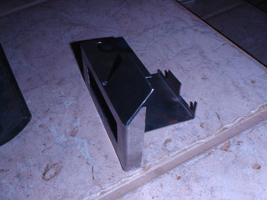
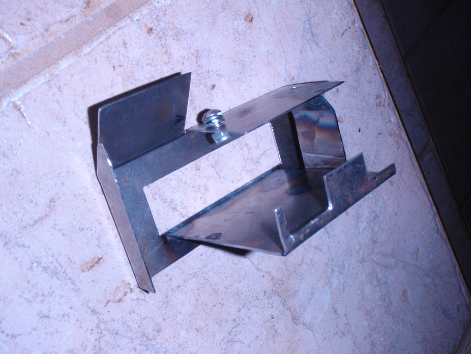
Last but not least, big milestone for me in the project, interior is fully wired (just need to tuck excess) and dash is in!!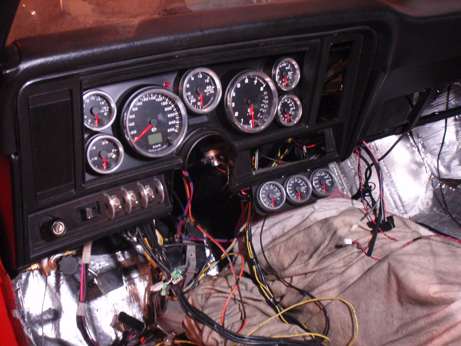
11-29-2011
It has been a lonnnnng time since I've ripped into a shipment of parts as quickly or with as much excitement as I did these guys tonight... maybe it's because I can look forward to finally installing something on my car that doesn't take hours upon hours of fabrication on my end.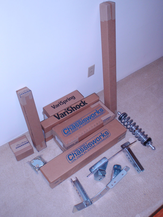
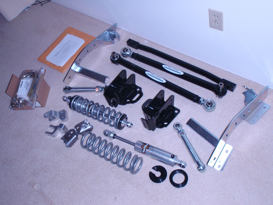
Lower links installed tonight without a hitch, tomorrow night will lower the diff and mock up the upper links and shock cradle to check ride height.
I hate to say it, but I know I can't leave well enough and if this setup simply sits way too high (been mentioned a couple times on pro-touring.com & lateral-g.net), I might (z'd?) the upper shock cradle into the trunk a bit to lower the rear of the car another 1-1.5", as well as space the lower axle pad pieces to keep lower link geometry similar (as horizontal as possible at ride height), while the slightly more angled upper links would decrease antisquat to some degree.
12-1-2011
Bottom cutout is for Greddy boost controller, top cutout is where the OBDII connector will mount, all in the name of stealthy... or Clint...should I have mounted the controller on top of the dash in plain obvious sight for all to notice?? haha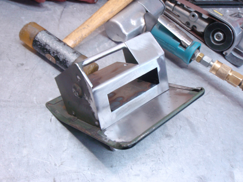
The more I look at this rear suspension setup, the more I like it... not just regular wearable heim joints, or bind-inducing rubber or urethane mounts, but over-sized hardened stainless fully-rebuildable "Johnny Joints"...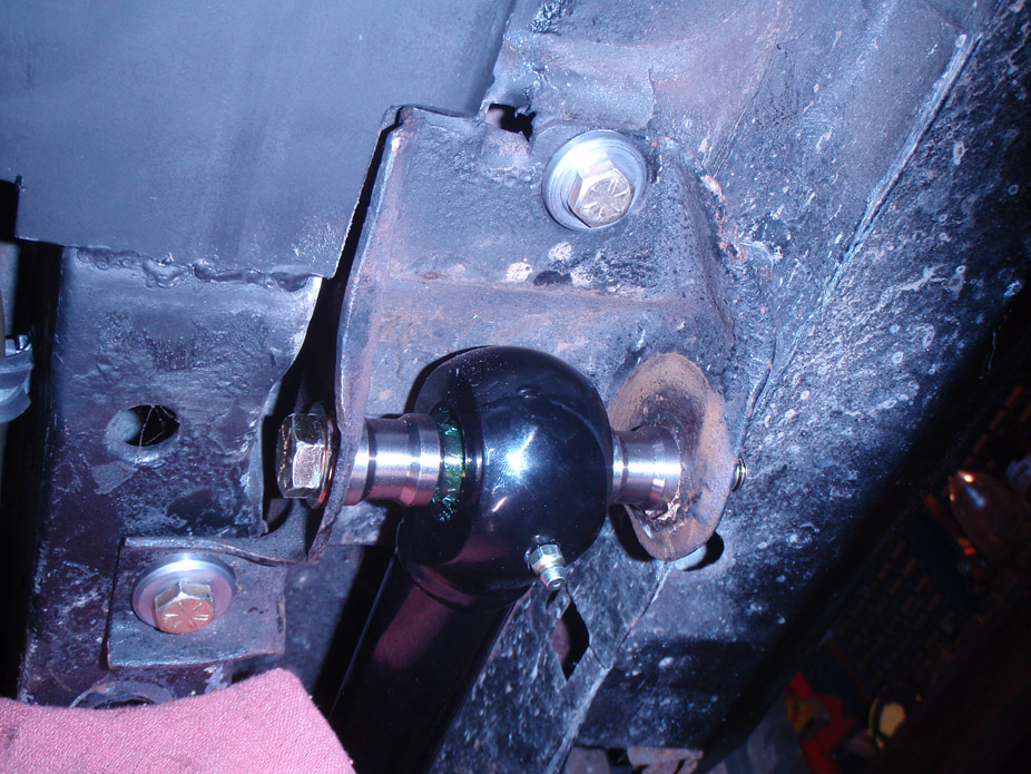
Car body is supported about 18" above ground and tires are touching the ground... I could practically call this car a trophy truck now...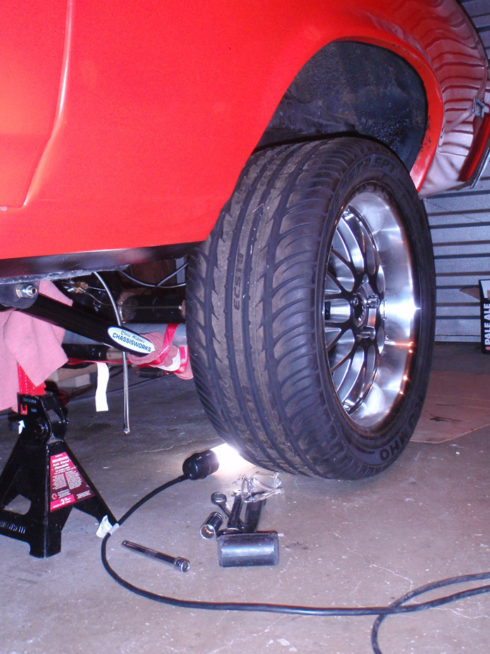
My ghetto-fabulous setup for making sure the rear didn't flop around fore/aft as I was lowering it by the center, since it was only connected to the lower links to start with..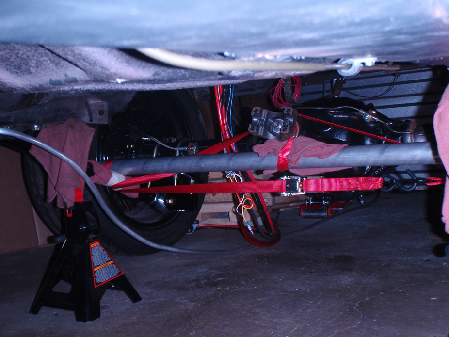
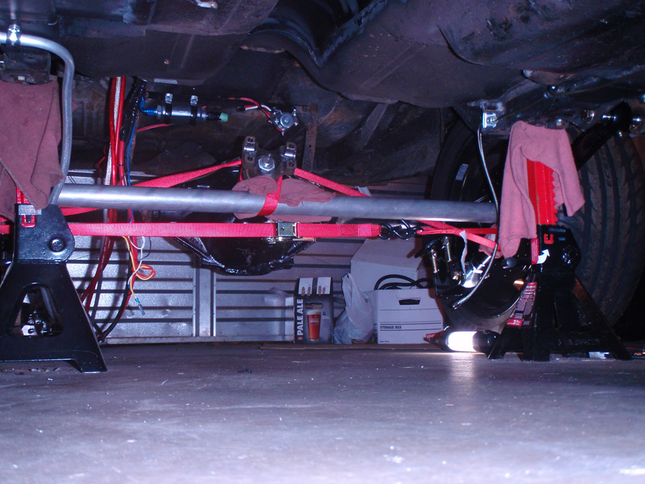
Upper links and cradle are in for mockup, will post pics once shocks are in to check ride height, clearance, etc
No need for any such centering device since the 4 link is triangulated... Also no sway bar for now, want to see what the handling is like first before I dive into that.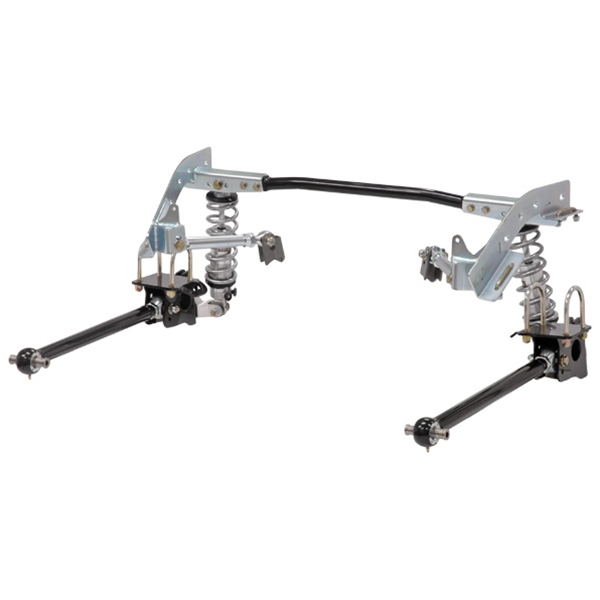
I will however be putting in a brace from framerail-to-framerail for the upper link front perches, to tie them together and spread the load across both framerails.
12-2-2011
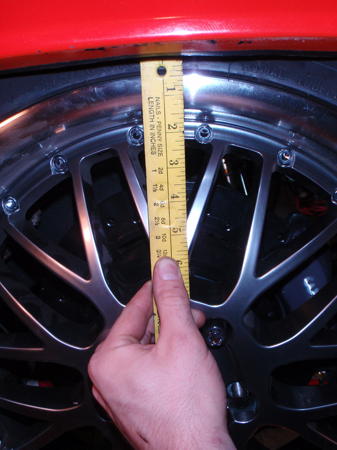
Lowest possible combination, full compression, for anyone interested, 18" rim is tucked 2.0" above fender lip...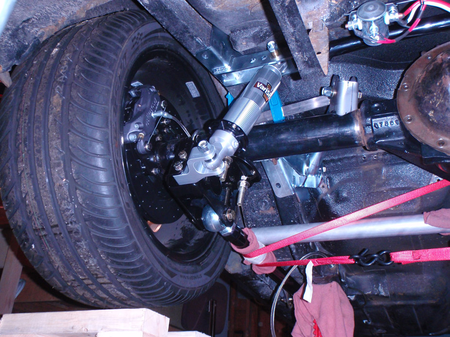
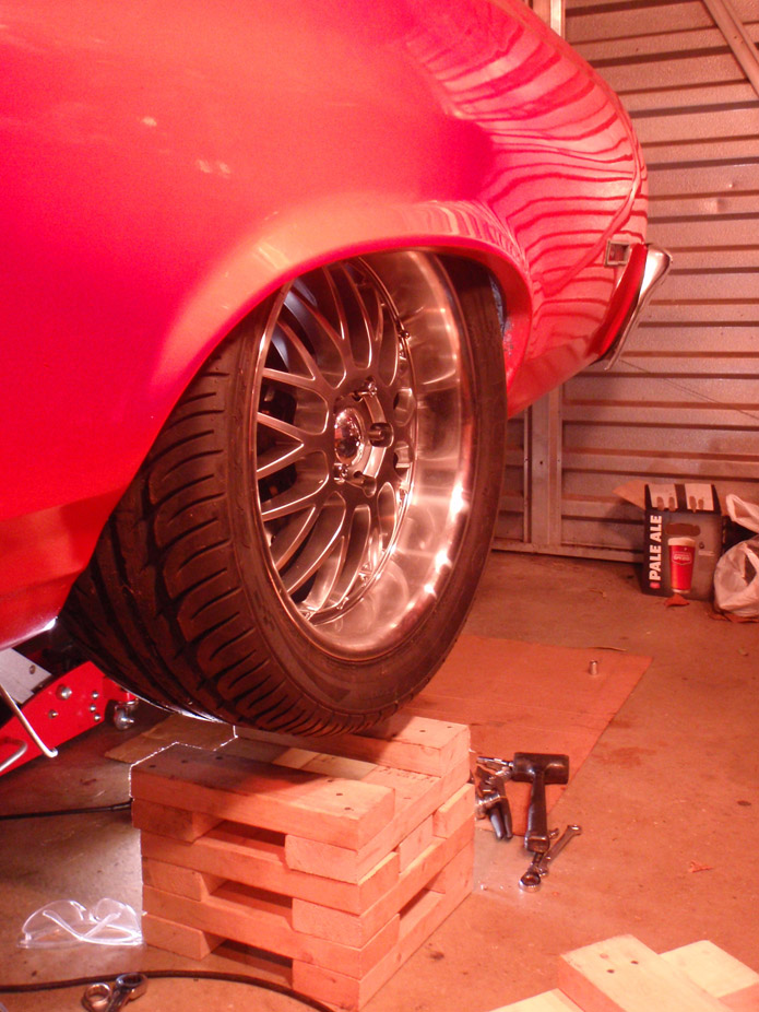
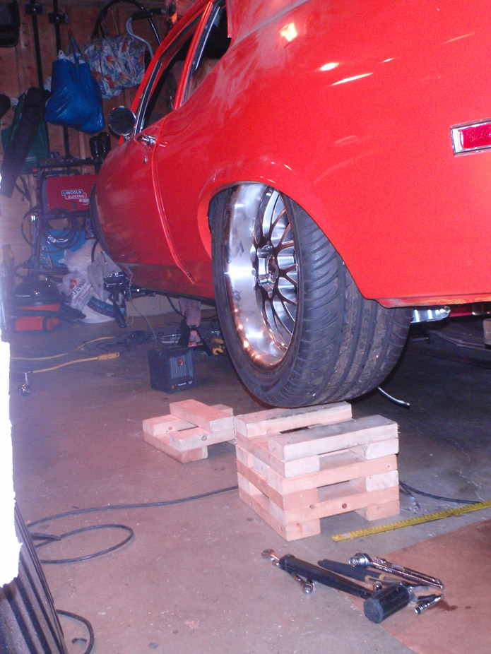
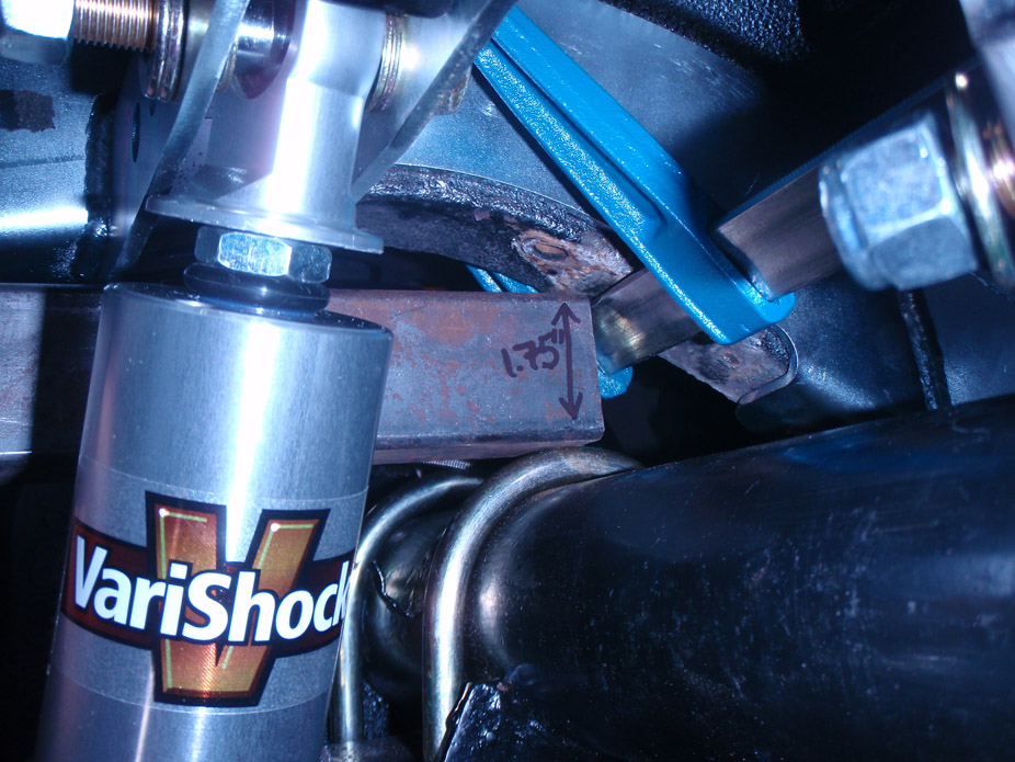
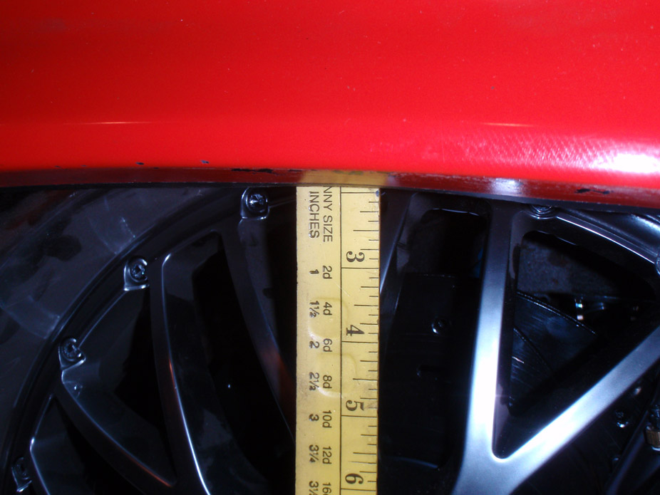
Recommended ride height of 13.5" eye-to-eye on the VariShocks = coilover right in the middle of the 5" travel with 2.5" of bump travel and 2.5" of rebound travel.... 18" rim is 0.5" below the fender lip. I have deep thinking to do about this.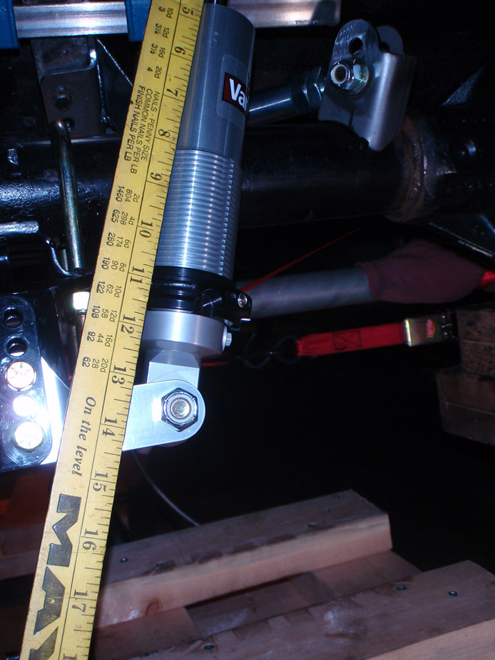
12-10-2011
Oh the good old days... buh-bye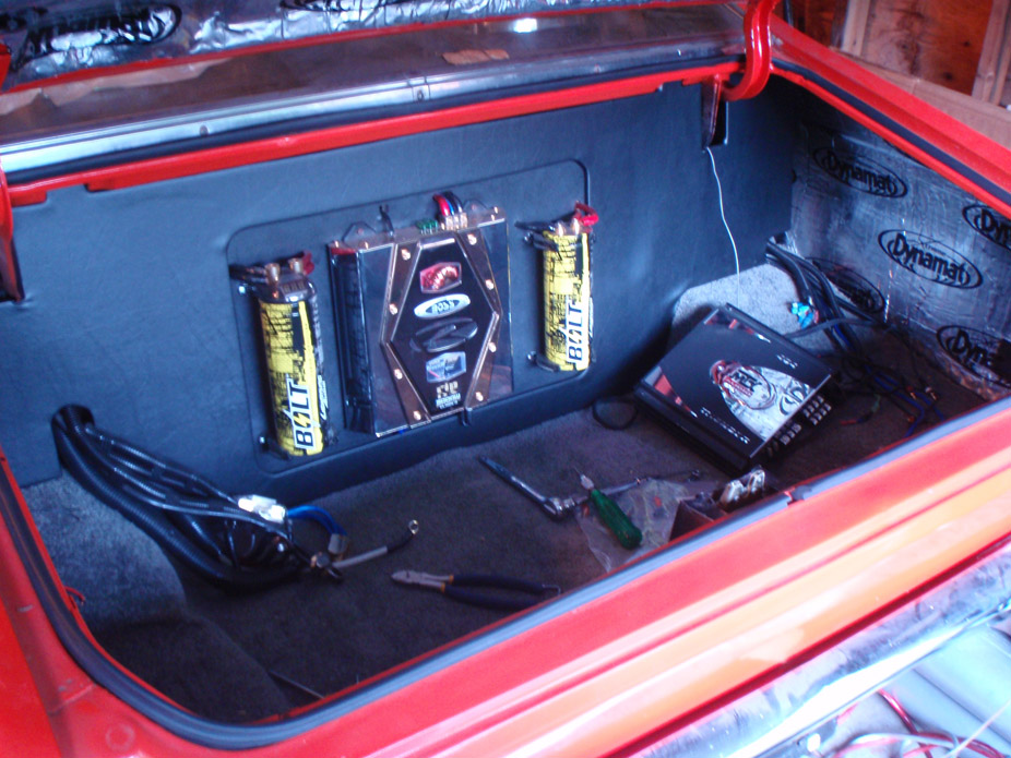
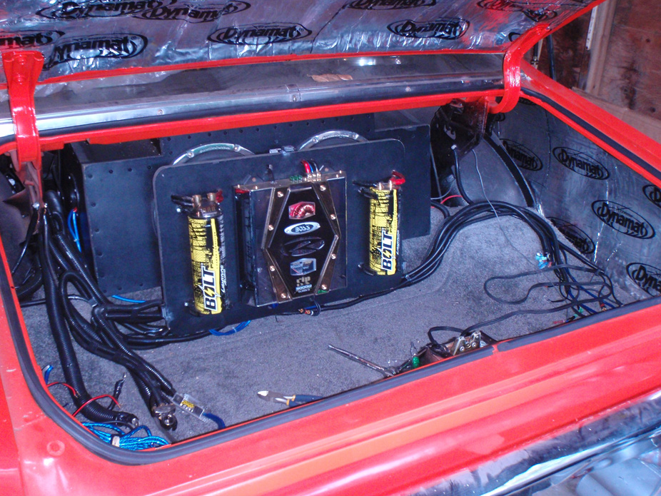
So heavy, and in hindsight, so insanely loud...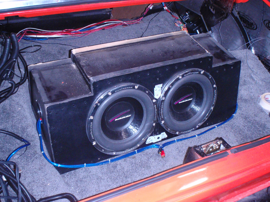
Battery tray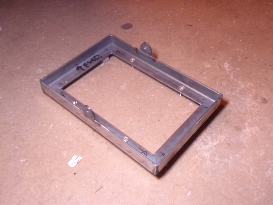
Oops I dropped the angle grinder and look what happened..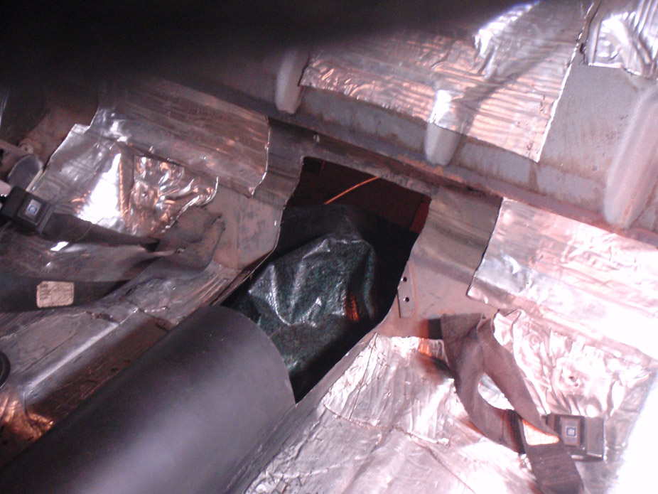
Wow i'm getting really clumsy with this anglegrinder, i keep dropping it all over the place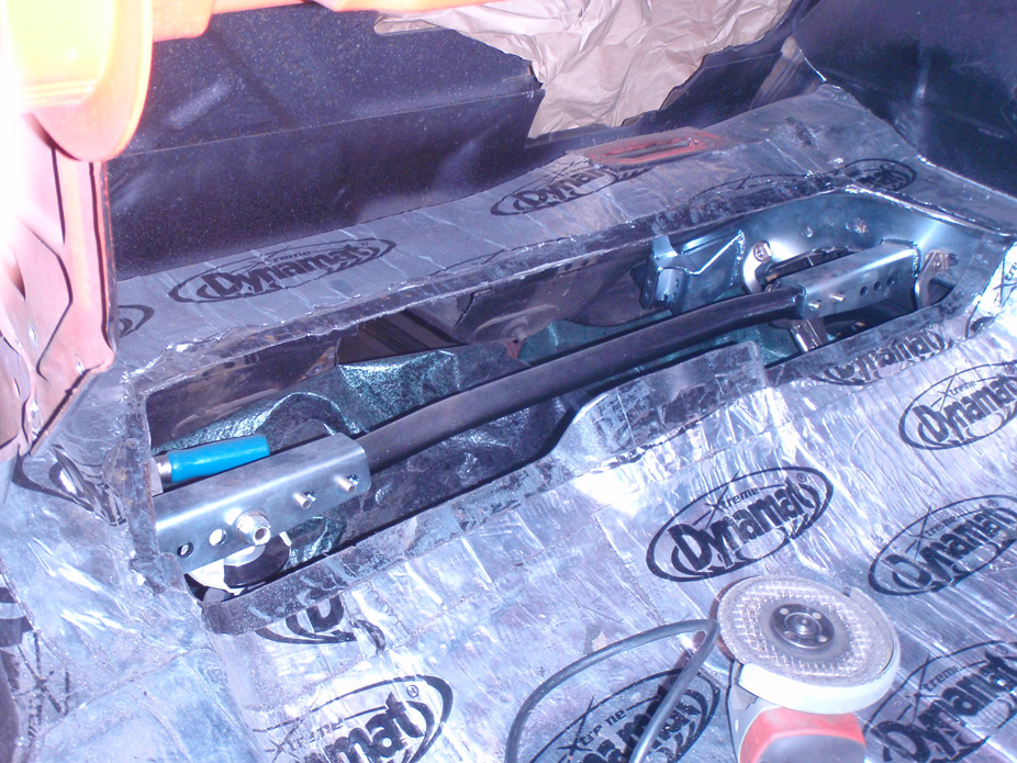
I can't leave good enough alone, a couple mods to the G-Link happening, below is the new max-compression height, 1/2" framerail clearance to axletubes while tucking 3.75" of rim, so ride height will tuck ~1.25" rim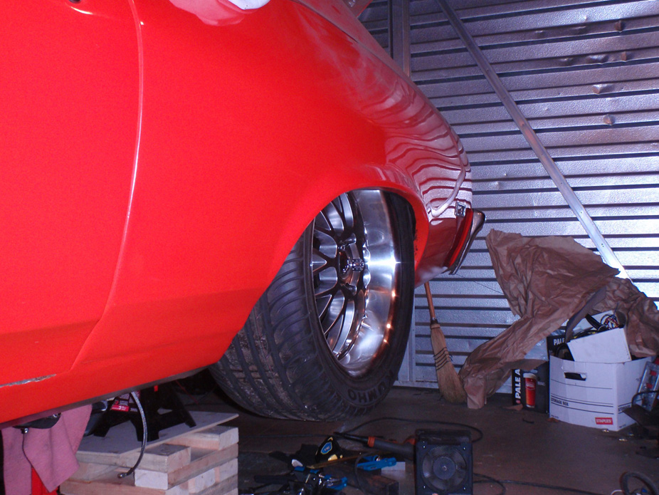
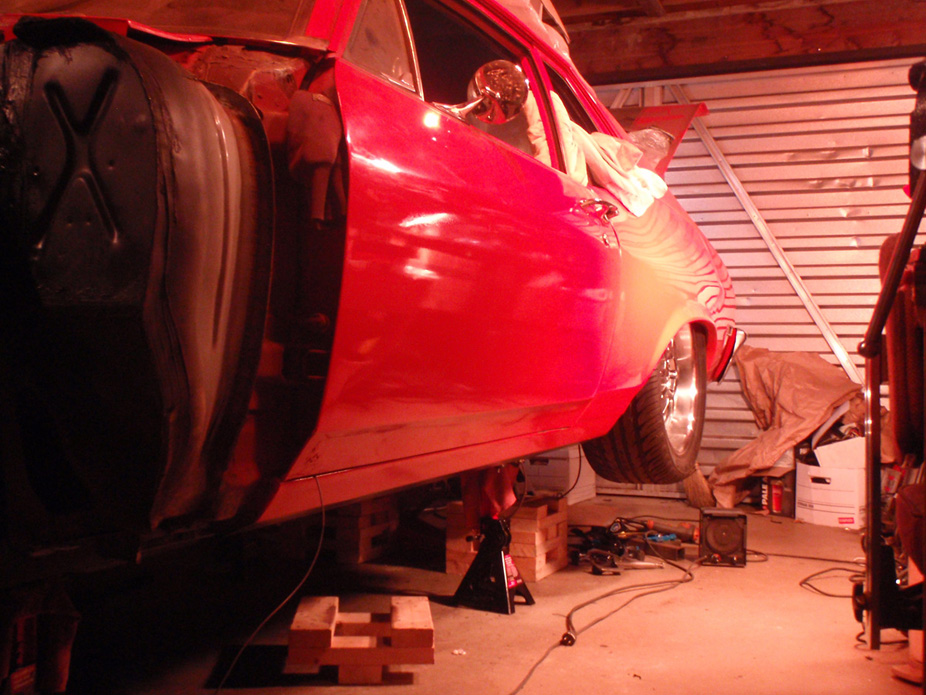
12-15-2011
Turns out my Speartech harness didn't come pinned for the A/C high-pressure sensor wire, so everything came apart for me to fish out a non-used wire (brake pedal signal) and re-pin it in pin/slot #14, which was then hooked up to the wideband AFR signal for laptop datalogging of the AFR's..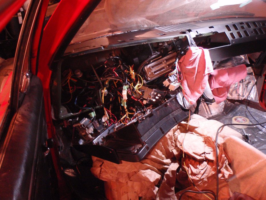
And then things got even worse, I dropped the 4link shock cradle brackets and, well...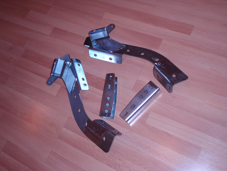
Luckily I had easy access to where they're supposed to go, now just to JB weld them back in place..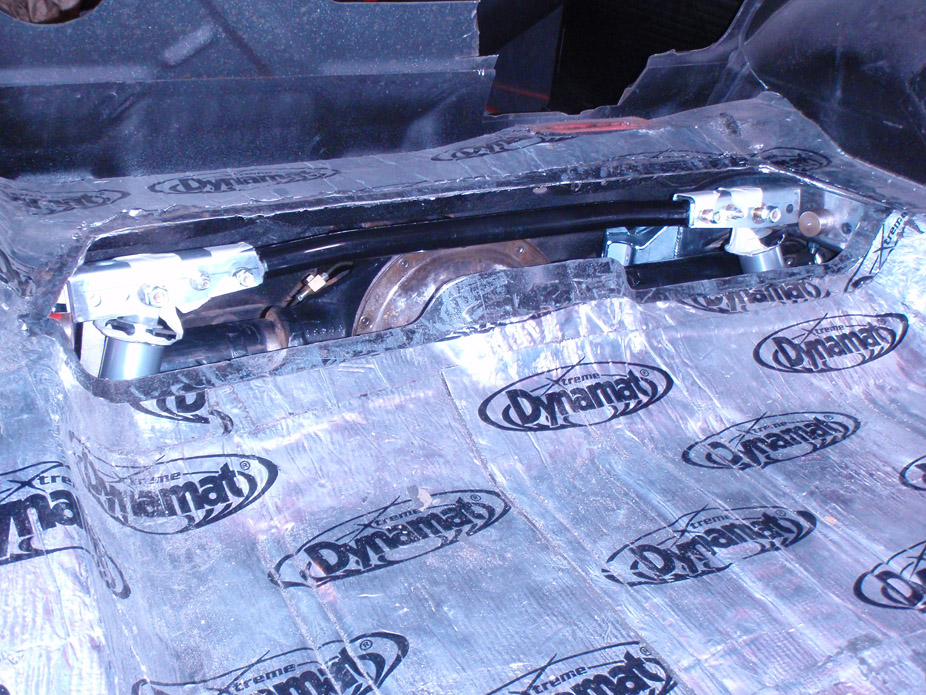
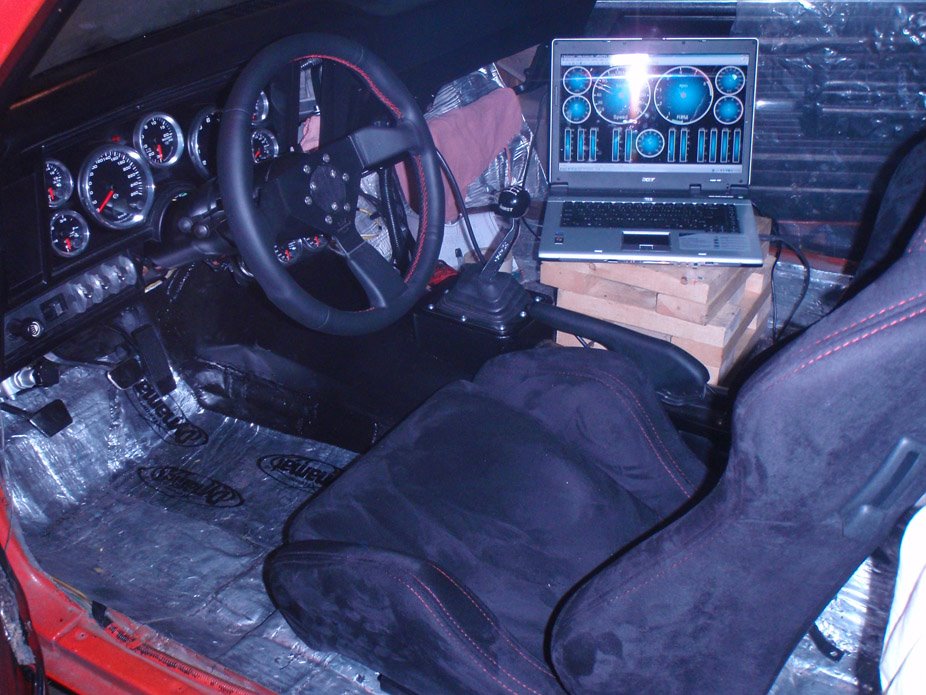
And finally things started to look up, got a glimpse of what "the office" will look like..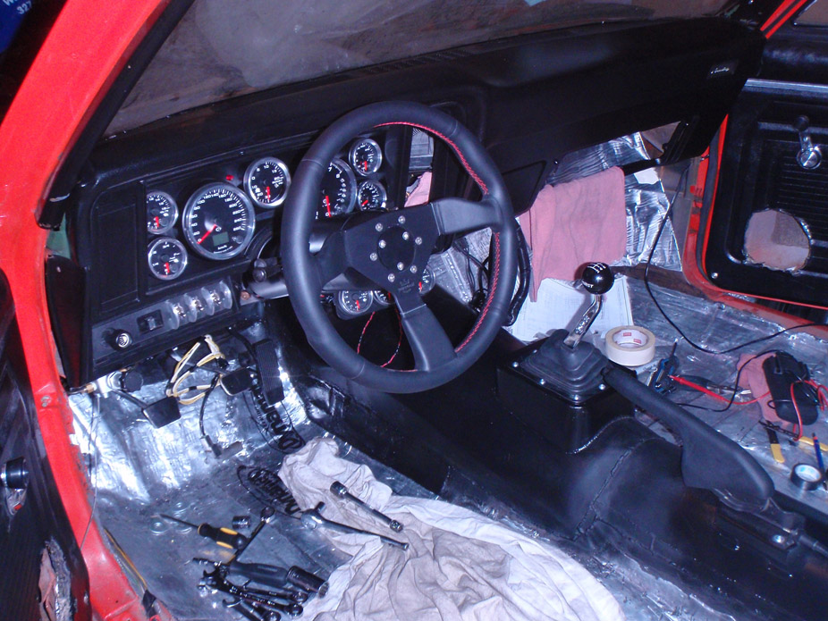
I love how close the shifter is to the steering wheel. Hard to tell but shifter is nice & close at about 5-6" away form the wheel (350mm diameter)..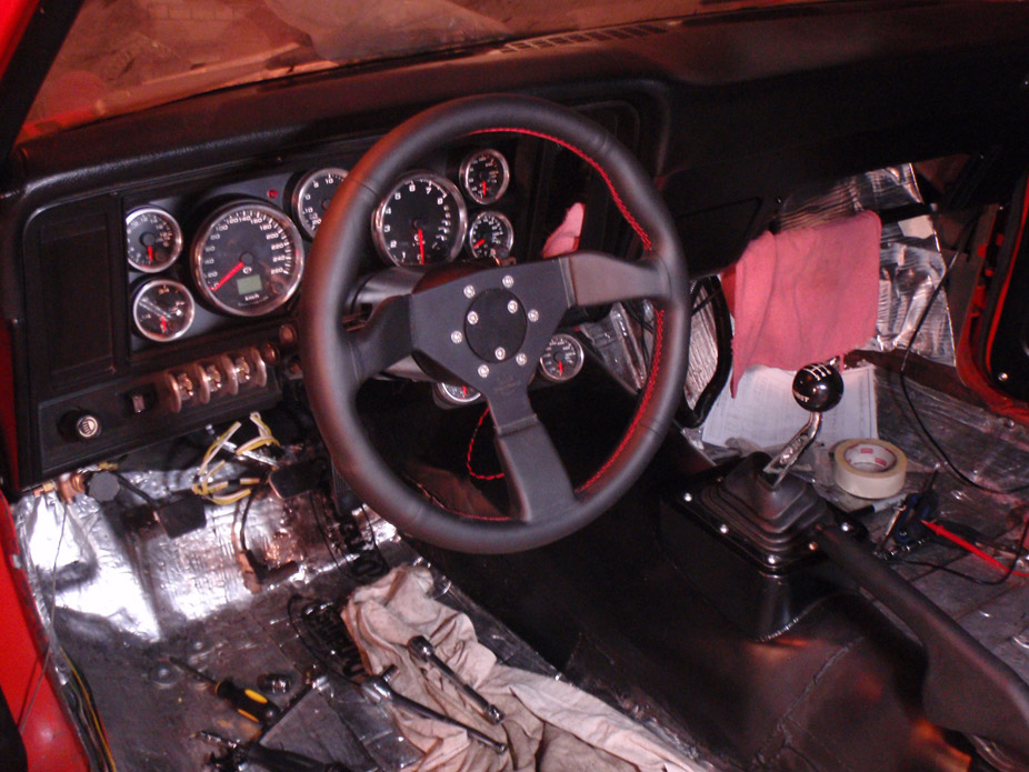
12-19-2011
Thanks Clint... everything worked out perfectly, was nice to finally sit in it and feel the fitment of everything.
The shifter is in a perfectly natural place to the wheel.. nice and close!
Possibly one of the best mods I did was flattening the floorpan and pinching in the trans tunnel right around the gas pedal so that I can have my foot vertical, plus almost an entire shoe's width between the gas pedal and the tunnel so there's plenty of room for the foot from the brake pedal in lazy-driving mode. I moved the gas pedal towards the brake pedal 0.75" closer than the setup in the 240sx daily driver, and heel-toe (for my size 13 it's actually leftside-rightside of shoe haha) is more than natural.
Was gonna wait for other updates but I guess I'll add this pic now, getting close
12-25-2011
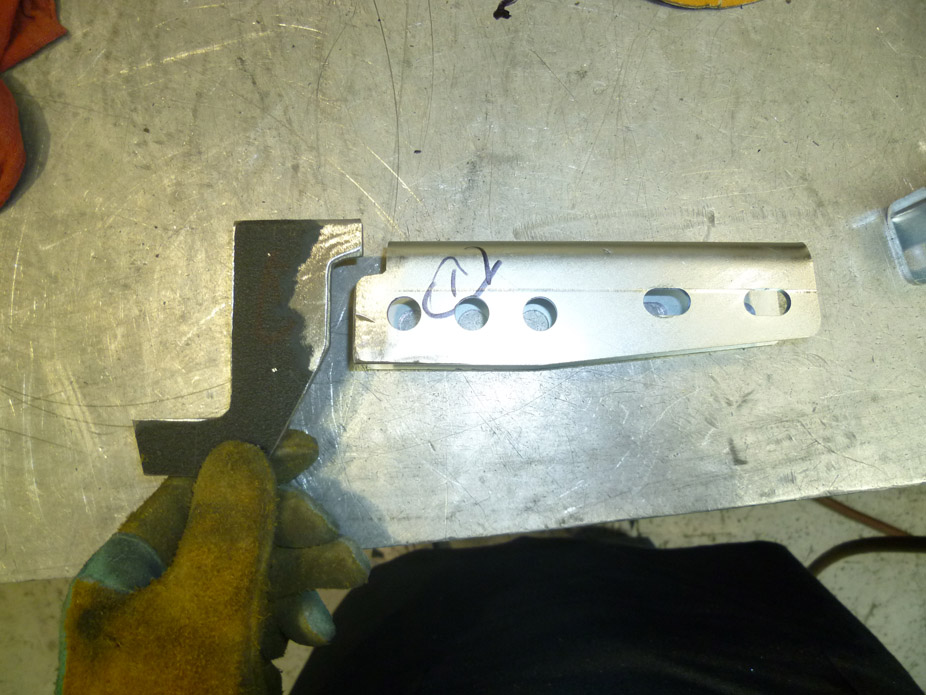
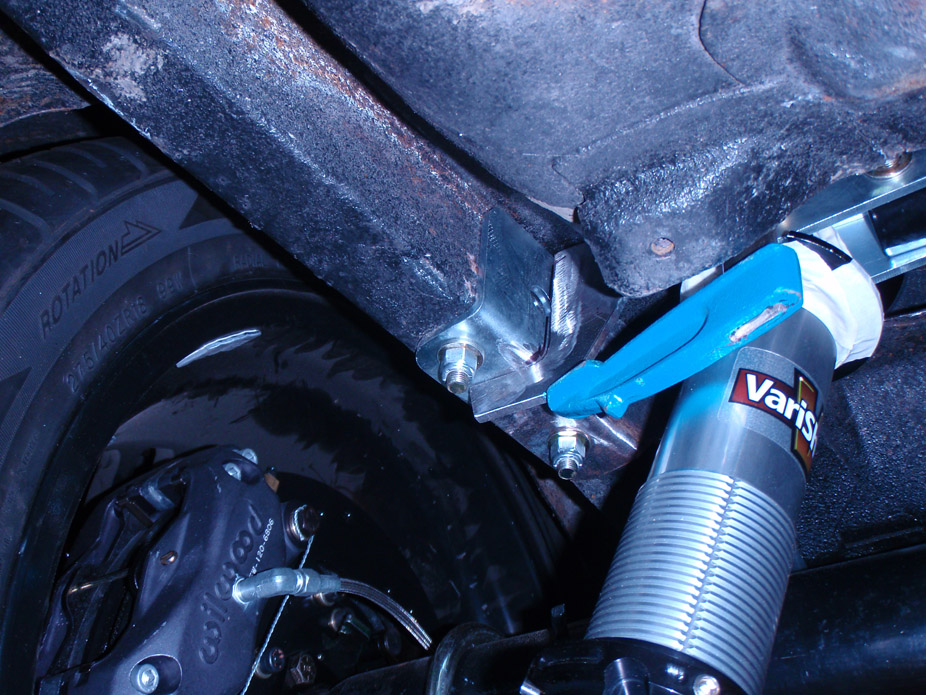
Modification of G-Link shock cradle/cross-member. Tried to create notched "adapter" plates to raise the cradle cross bar ~2". Notches are so that the brackets "capture" the bottoms of the frame rails and "capture" the tops of the shock-mounting brackets, so that the load from the shocks isn't supported 100% by fillet welds in shear. Along with these notches, everything is 1/4" plate that has been chamfered at all welds and lots of filler rod used... these guys are beefy enough to make me feel content.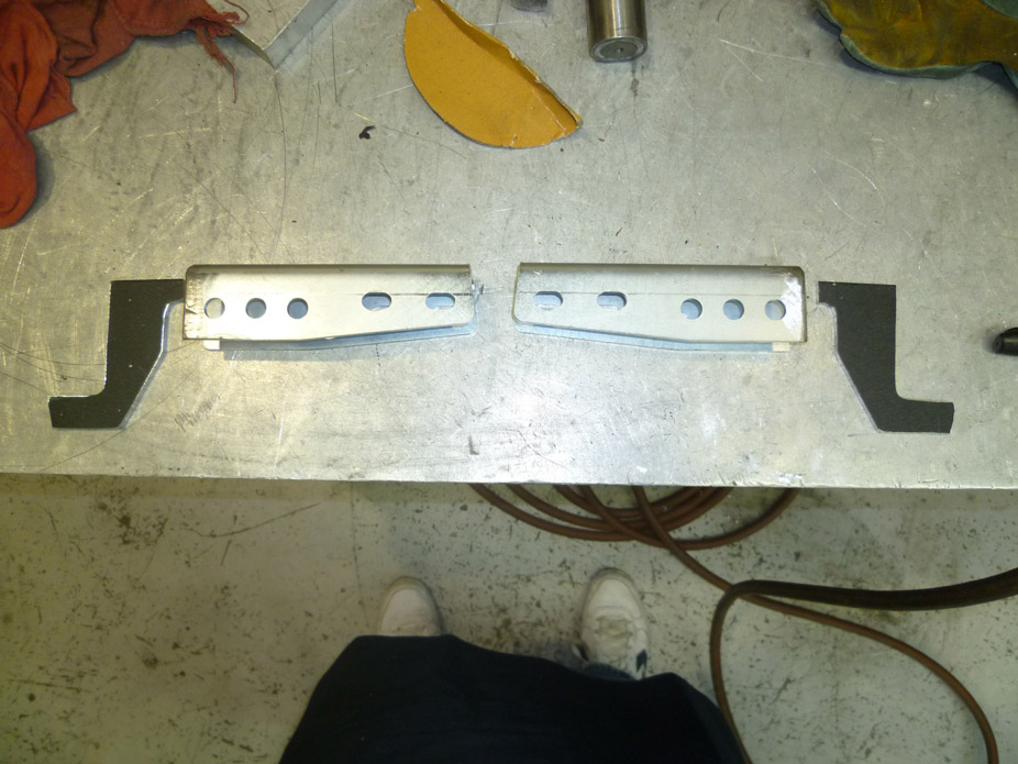
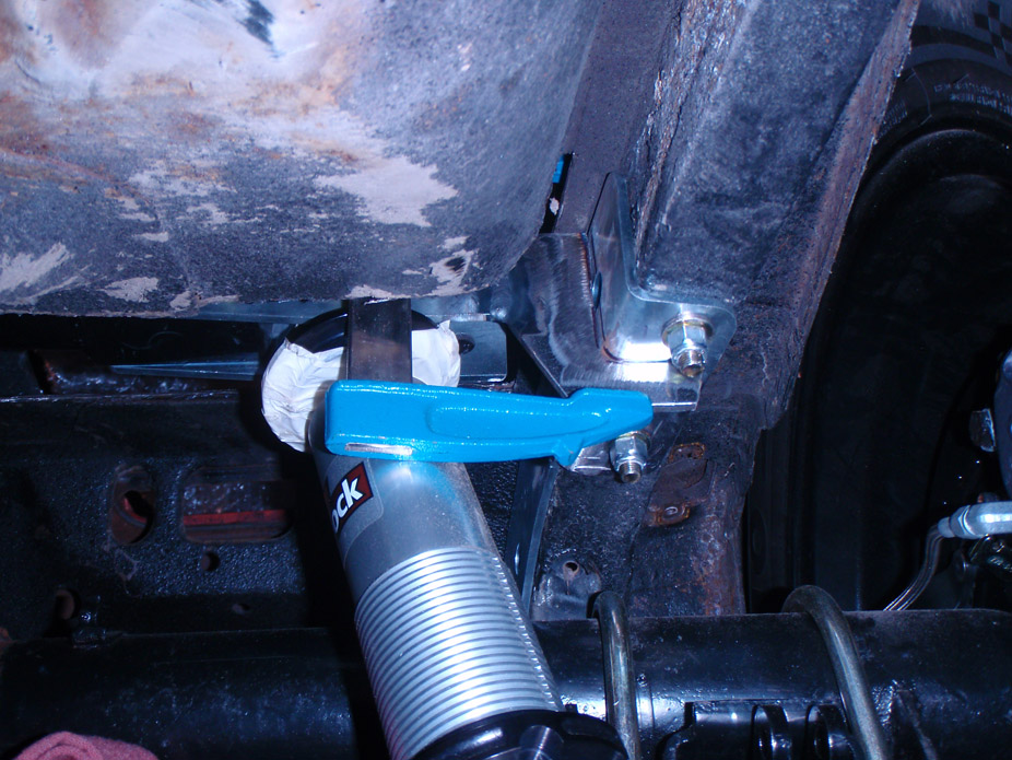
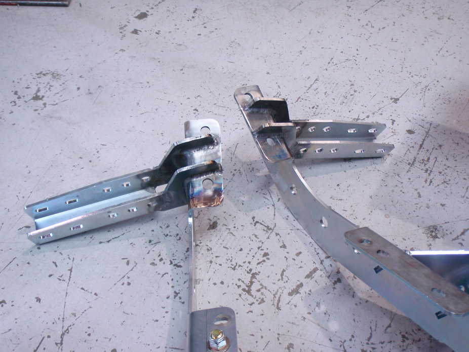
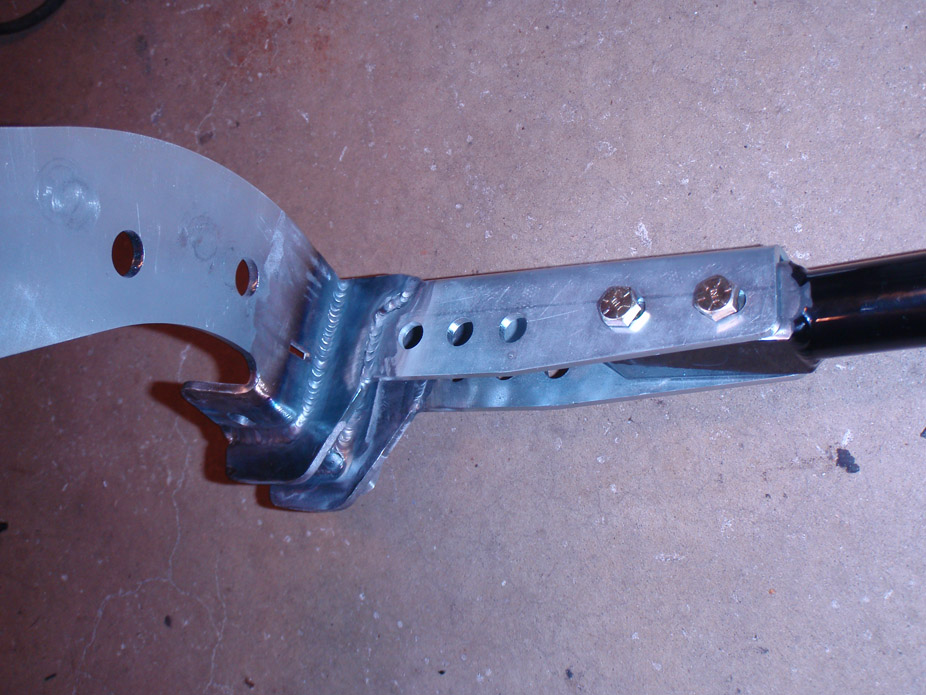
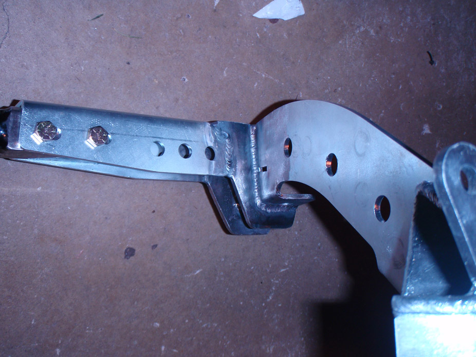
Driver side fender on for the first time in.... 2 years maybe? Need to notch the fender a little for room for the oil cooler which will sit behind the driver side headlight.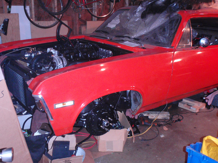
All it really needs until it can be fired are brackets to hold up the oil cooler, the oil cooler lines, the turbo feed line, then coolant and oil... almost starting to look sorta finished... exciting!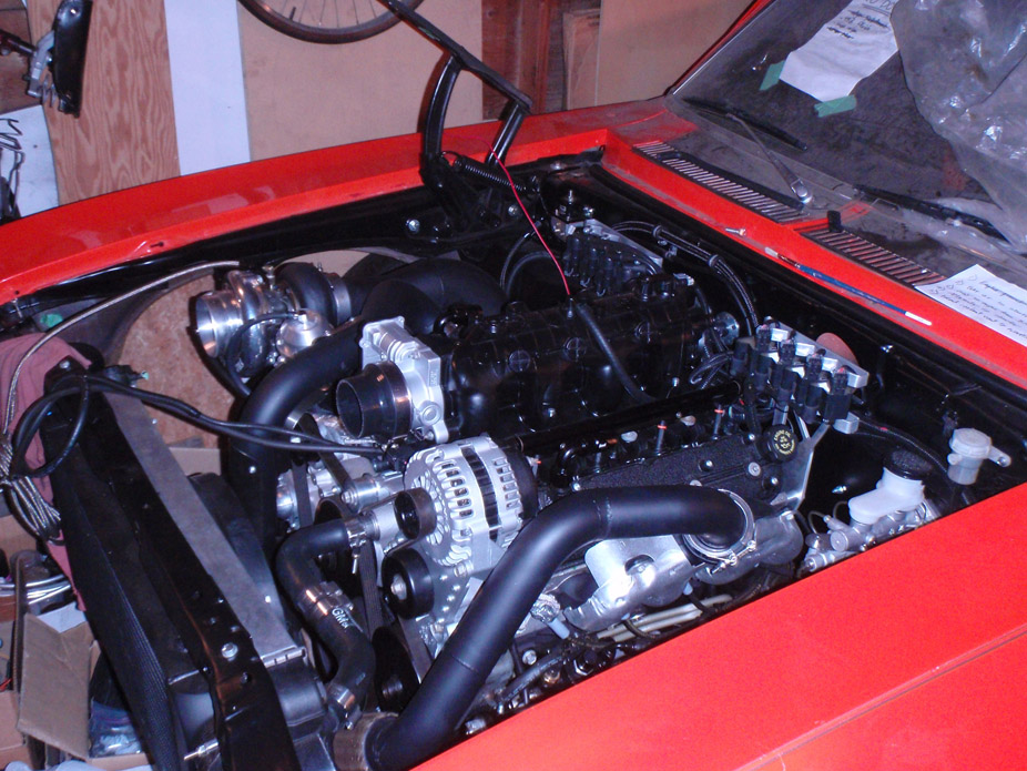
12-31-2011
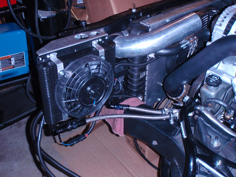
Oil cooler in and plumbed. Now just need to put the tank back in and hook up the fuel supply/return lines, and fill her with coolant & oil!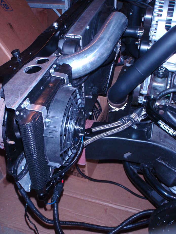
1-21-2012
Mark thanks for the offer but I can't help but feel a bit of impatient meanness behind it. I thought we were friends??
Tony.. (this is for ride height)...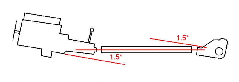
2-12-2012
Work has been crazy but slowed down, this is what I've been trying to work on over the last couple weekends. Cross brace between the two upper control arm pockets to spread the load side-to-side under cornering as well as prevent the UCA's from wanting to 'pull' the framerails in together under hard acceleration. Frame rails are finally stripped clean (that was a shitty job) and bracket is clamped in place, ready to weld in after dinner.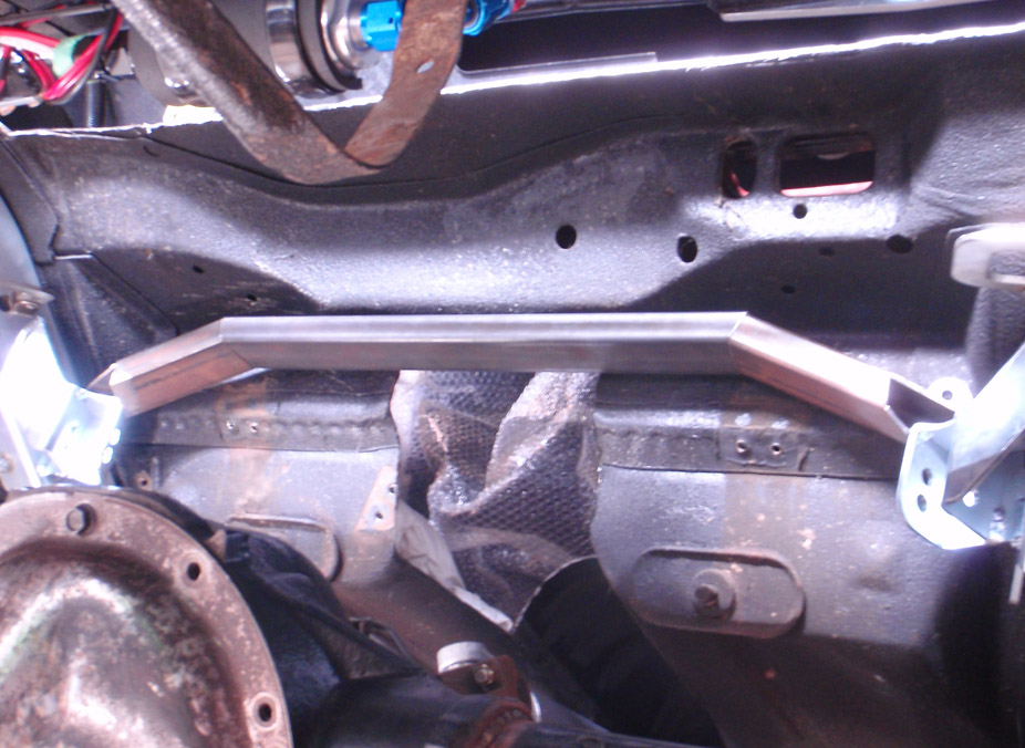
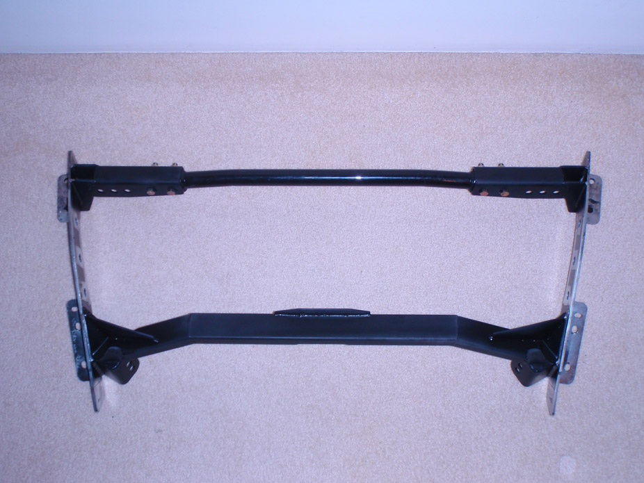
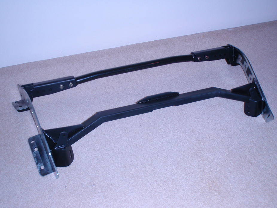
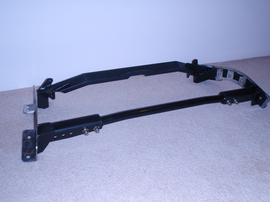
2-16-2012
Still have to complete some of weld bead on the upper control arm brackets on the rear axle, and install the tank, and pull an axle stud cuz the thread is screwed, but a friend is coming into town and I had to get it put together just a little bit to make it presentable.
It also appears to be stink-bugged a bit. I still have 1 hole left in the rear end's height adjustment, so after springs break in I might lower it a tad bit still.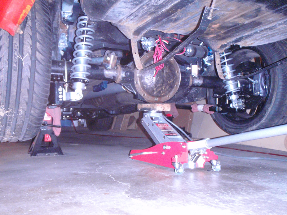
2-25-2012
Thanks for the comments.
I like the "built not bought" approach in general too.. was intimidating at first but there's no better way to learn, provided you can afford the tools to do the job moderately right. Now there are so few things that I would simply just buy, like the 4 link, but I couldn't even leave that alone.
I ended up ditching the Holset VGT turbo after hunting down a comparable Holset compressor map (for an HE35, supposedly a near identical non-variable vane version) and realizing that the compressor would simply be out of the acceptible efficiency range for my 6.0L displacement and the rpms it will end up running. I sold the Holset to a guy wanting to retrofit it on a diesel 5.9L and he was going to make his own vane controller for it. I ended up going for a Turbonetics TC76 with the F1 wheel, and 0.96 A/R hotside, talked to a handful of experts on this forum as well as directly to a couple turbo companies, and for my mild engine, medium-hp levels and medium boost, all recommended a T or TC 76mm turbo, with a 0.81 or 0.96 depending on how I wanted the "lag" to feel. To be honest, a bit of lag isn't such a bad thing for a streetcar that has hopes of even just a bit of decently good fuel mileage on the odd occasion.
The radiator I got for super cheap off craigslist, and it's for a 4.3. Not sure if it'll do the job, but I made sure the radiator/intercooler were jammed forward as much as possible to give a couple inches of extra room to the engine/accessories if I need to get a larger radiator. That's also the reason I didn't use an integrated oil cooler or put the oil cooler in front of the intercooler or rad. I'm using a Zirgo 14" 2750cfm fan, it's a generic speedparts store kinda fan, will see how well that works. I am crossing my fingers tho that the radiator does a good enough job, because the inlet/outlet are positioned perfectlyfor nice, clean, short rad hoses.
2-28-2012
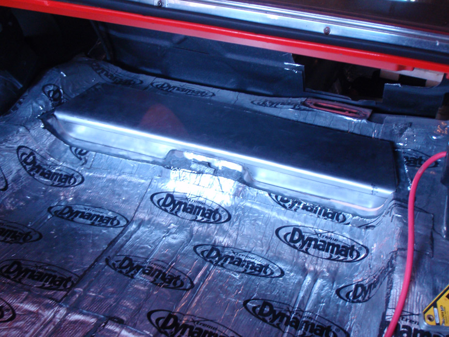
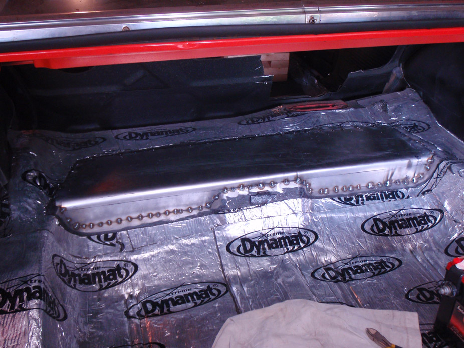
Despite having a cold, it was a good weekend. Trunk sheetmetal wrapped up. Rear end had brackets fully welded, painted, and filled with gear oil. 4link frame brackets fully welded in and painted. Fuel supply and return lines fully bent and connected (sans 1 return fitting I'll pick up tomorrow). Rear end in, final pinion angle set, brake lines hooked up. All it needs now is the brakes bled, and the exhaustwelded a bit and thrown up in there. Only things really left are to bolt the seats and seatbelts in, flash the PCM, and fill with coolant/oil. Pics: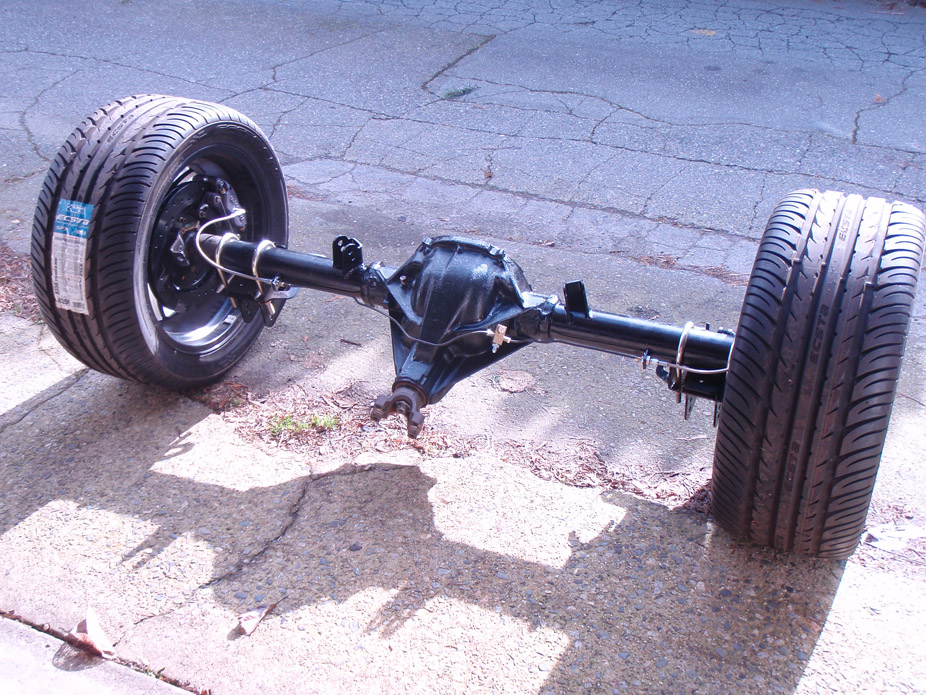
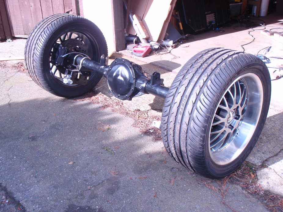
Fabrication by any means necessary...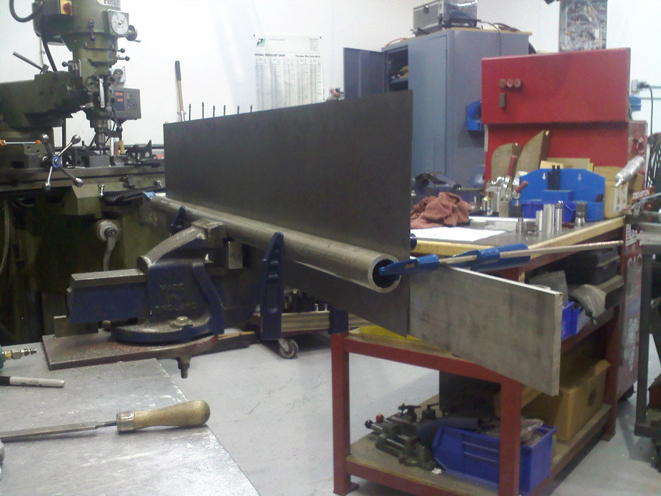
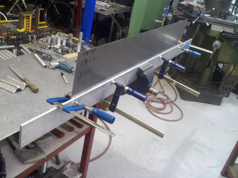
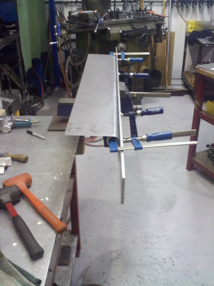
3-7-2012
Well at the final stages. Got all connections hooked up and flashed the PCM with the initial tune. I literally only need to find a gas tank cap and put oil/coolant in it before I can start it... slightly exciting!
Made a new upper rad hose connector that tee's the heads' coolant crossover tube into it. Anybody want the old coupler??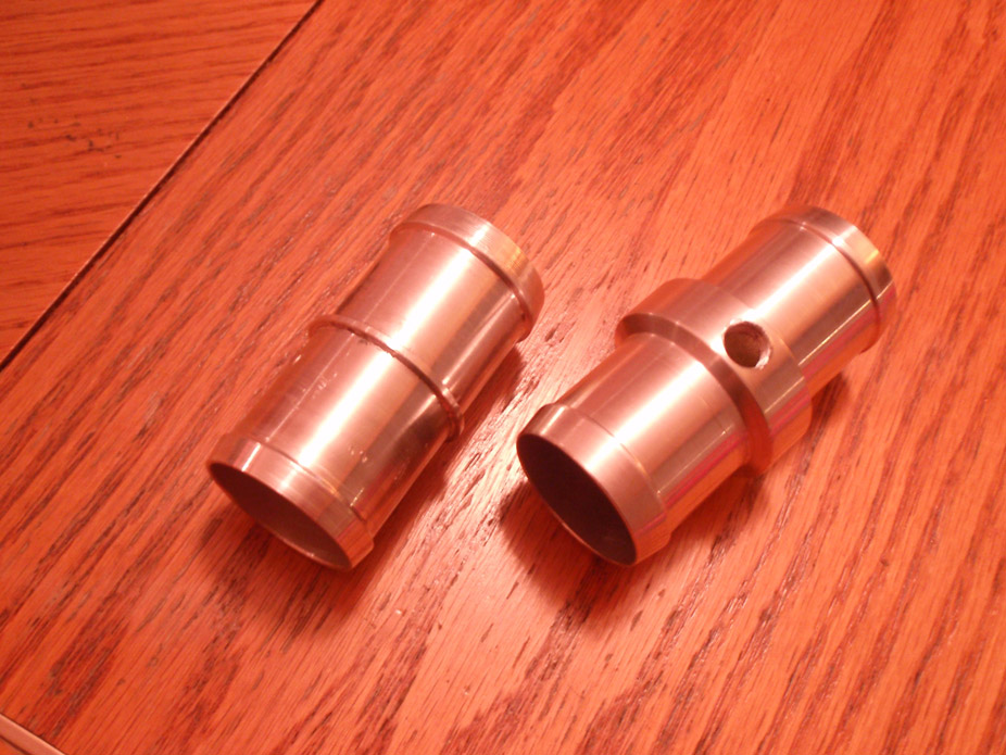
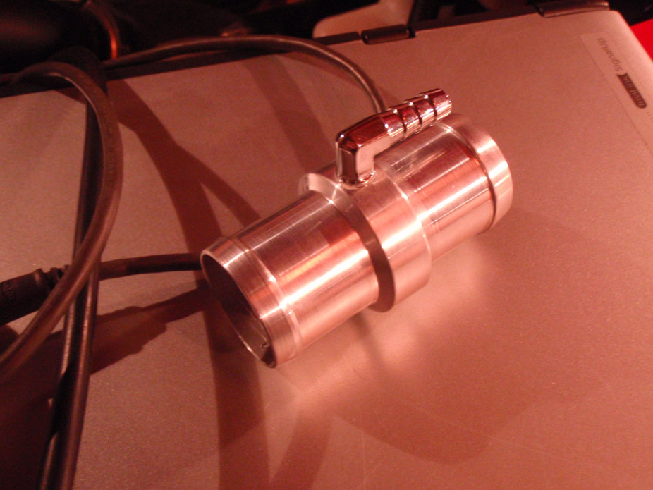
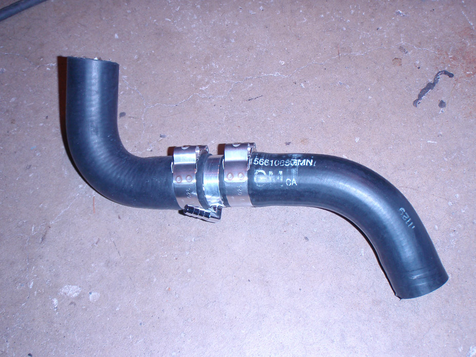
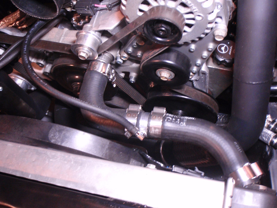
Look close but actually decent clearance..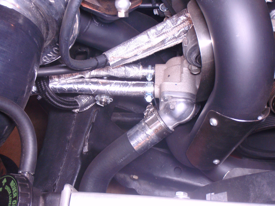
Going to add a battery disconnect on the negative side for "just in case", just need to finish the mounting bracket..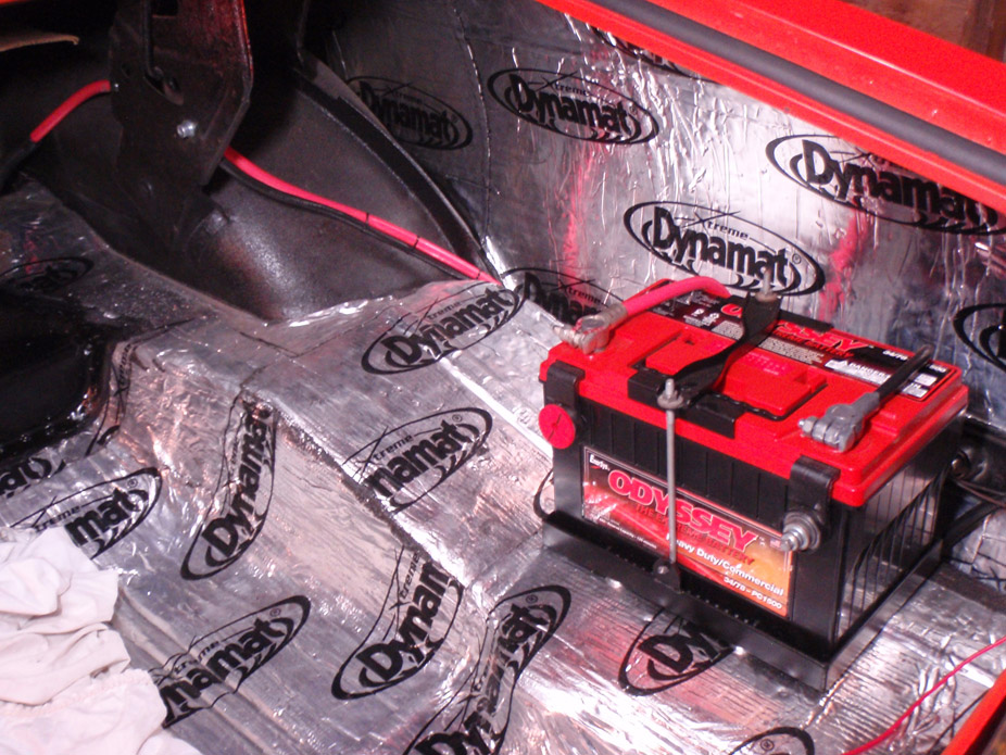
Convenient passage with hold-down tabs and everything in the passenger kickpanel area. Doesn't look it but there is a recess where the 2gauge power wire loops into the vent hole, so the wire isn't just protruding on the edge of the hole there.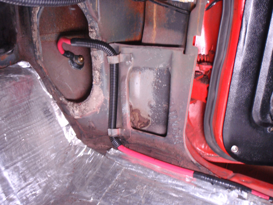
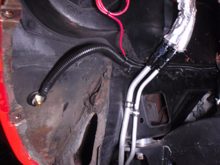
3-7-2012
If there's one thing I've learned from bikes, is that even if a cable or hose is mounted securely or doesn't even look close to touching something, with vibration it will, and over time even a nylon hose can wear right thru metal. Not good. So the turbo feed line in all its abrasive braided stainless glory is 100% secured and isolated from any nearby objects to minimize wear it might have on nearby stuff.
Due to all the turbo pipes and merge crap going on in front & on the passenger side of the engine, I didn't want the turbo feed line snaking through all of that, so took a more roundabout way to tee it off of the oil cooler outlet port.
Bad angle but there is about 1" of clearance below the line to both aluminum cold side pipes..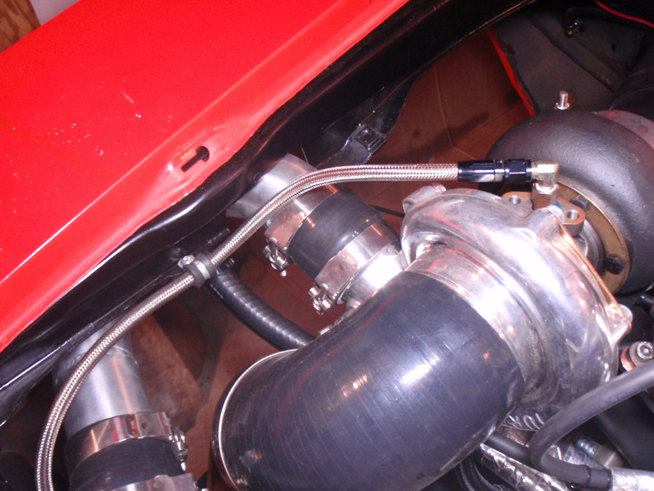
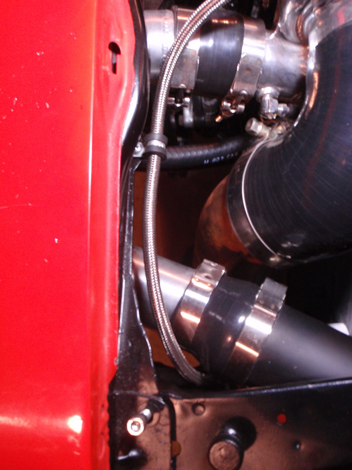
Down around the framerail and over to the driver's side of the car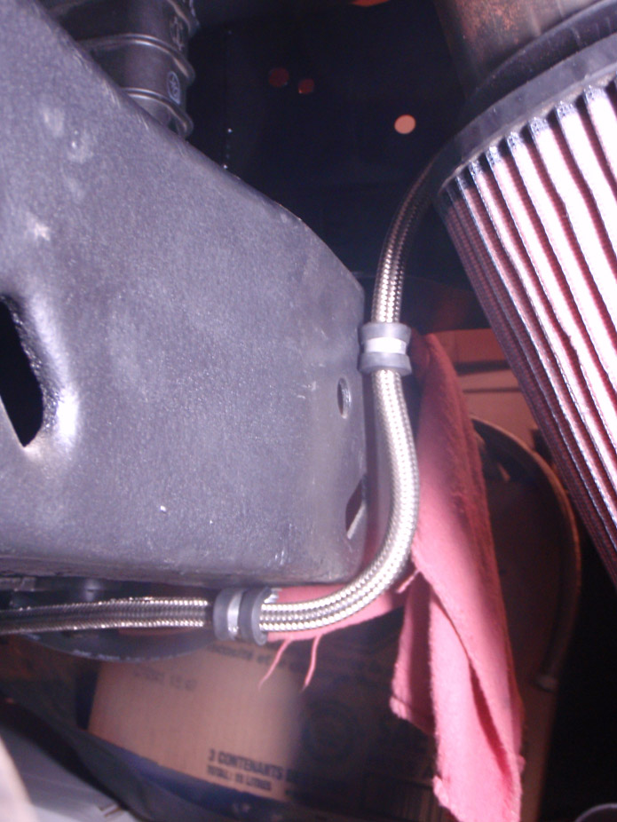
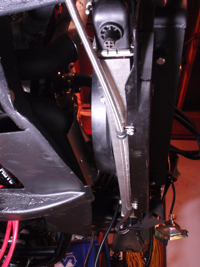
Again because of the angle it looks tight, but the hose isn't actually stretched here. Tee'd off of the exit port of the oil cooler.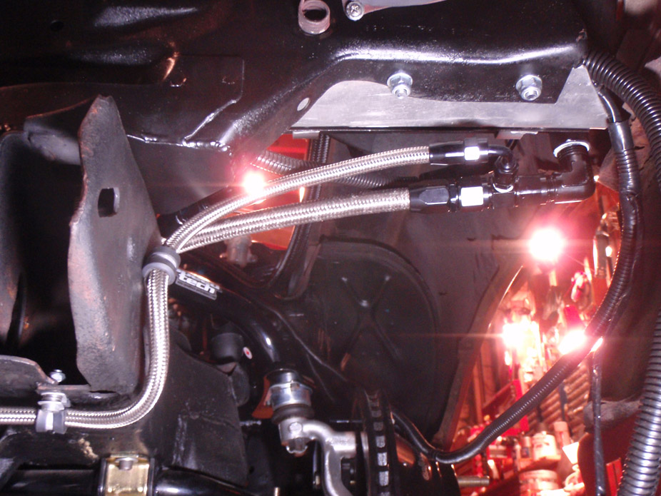
3-13-2012
I only plan on trying to drag race it once.. when it's tuned and driving nicely, just to see what it can do. If they let me run down the strip, cool, if not then I guess I'll have to stick to abusing the crap out of it on the road course and having a bit on the street.
I rigged the fuel pump right up to the battery so I could start it sooner, so it is not being powered by the PCM-controlled fuel pump relay that came wired into my Speartech harness. I know the PCM was still on when the key was hot and in cranking, because the HPTuners scanner was showing rpm's when cranking as well as ambient temp and throttle position, however I don't recall if the injector bank gauges were flashing. I have a feeling the injectors weren't getting a pulse. I'll try cranking it tonight while scanning and first seeing if the fuel pump relay is outputting power. If it isn't then clearly the PCM doesn't want to give the engine gas, but if it is outputting power and the injector banks just aren't pulsing, I'll have to do some digging thru my tune. Arg.
VATS was disabled on the new speed density tune I wrote to the PCM, however I should read that tune back onto the laptop to make sure everything copied over right. Mark had a good idea that maybe in the process of the Write-Entire from the previous MAF setup to the new 3bar Speed Density tune, the VATS might've been re-enabled somehow, if that's even possible. Altho I would think that if VATS was re-enabled then the engine would at least try to stumble/catch/fire at least for a couple seconds.
3-19-2012
I was out all weekend with food poisoning from friday night, which was really shitty because i wanted to dedicate all weekend to getting this ****** running. Like Mark said, gotta start at the basics. Will check spark, injector voltage, fuel pump relay output voltage during cranking (of computer controlled relay, right now the fuel pump is just rigged to the battery). The one thing that is suspect in my eyes is that when I re-flashed the ECM back to a MAF configuration and loaded the previous tune on it, it still cranked and all that but was still not giving the injectors a pulse.
Only things I have changed hardware-wise since the engine last ran are:
1) MAF wiring snipped all except IAT sensor, which I re-wired to a Typhoon sensor, which was reading 7 degrees celcius when I was cranking it, which makes sense because it felt that temp in the garage and the coolant temp was reading 6 degrees
2) injector plugs re-wired to USCAR plug from the stock truck plugs (EV1??)
3) different pedal. I wanted to redo my initial DBW frankenpedal but a guy wanted it and also had a stock truck pedal so we traded. I'm not getting any pedal DTC and the pedal reads 19% just sitting there and 100% when floored.. could it read properly but still let the TAC module give the computer a code. I remember reading Crosstraining's thread about his pedal making his ECM not want to fire.
I have ECM ground to the dash, harness ground to the head, and block ground to the subframe.
I am getting a P0622 DTC (only code being thrown) for bad alternator f-circuit, not sure what that could be but I'm thinking because I painted the alternator body (masked the coils) silver, could the alternator body not be completing ground to the head/block and this screwing with whatever this f-circuit reading is?
Also, this was a Speartech harness that ran great the last time I fired the engine. It has 4 fuses all tapped into one IGN wire, and the fuses were all good last time I checked but I will recheck.
Cars suck.
3-22-2012
No real advantage to the Typhoon IAT I don't think , other than it uses the right plug and the actual sensor is very low-profile so it shouldn't interupt airflow much.
Checked the injector plugs, I get 12V when switched on, so the injectors are getting power. Other wire didn't have ground, but would make sense since the injector pulse I'm lacking is a switched ground?
Checked the plugs, they aren't sparking when the body is grounded.
Heads are grounded to block, block is grounded to frame. Harness ground terminal has continuity to subframe ground location. PCM ground has continuity to subframe ground location.
Upon cranking still zero injector pulse according to HPTuners.
There is also zero output voltage from the fuel pump relay 12+ output wire that came pre-wired into the Speartech harness.
Just had a thought. I can't remember if I tapped the "IGN On" hookup wire on the Speartech harness to the Run wire or Accessory wire on the body harness. Maybe switching to the 2nd gen Camaro steering column I have now (was stock Nova one before) had a slight change in the wiring/connectivity of the ignition switch box in the column and allow an interruption when changing key positions? Would an Accessory output have power cut off to it during cranking? Might make sense since in every car I've owned the aftermarket deck would restart when going from Cranking -> Run. Funny though that on the HPtuners scanner it didn't seemed to indicate any interruption in power/sensor signals when going from ACC -> Run -> Crank -> Run -> ACC
3-26-2012
Mark came over on Saturday. I thought it was gonna be something like poke at a couple sensors and look at a plug and then we just scratch our heads at the computer screen, but we actually got a good amount of stuff done. We got it to fire a good couple dozen times but it would never catch and stay on, would just putter out after 1 second. And no.. VATS is not on.
1st problem was the switchable power connection to the computer.. it was connected to a lead on the ignition switch that's only powered during Run. I had to do a bunch of poking around after Mark left and found out that the switch on the 2nd gen column I have doesn't have an ACC power out.. no combo's of switch leads at least. Then we found the lead that gets power during Run & Crank.. but there was a brief power interuption that the PCM didn't seem to like. Found a power combination of a switch lead that is hot only in Run and then another that is hot in Run & Crank, and now the computer gets uninterrupted power during cranking. And so injectors get pulse during cranking!
Also found that the MAP sensor I was thinking was 2bar was actually 2.5bar... shouldn't change too much but is another source of error. Going to pick up the proper 2bar sensor after work today.
Apparently my injector offset table is zero'd out, which I'll have to compare with some other tunes tonight and fix that. Will try and start it up again tonight, hopefully all goes well.
Obligatory picture. Texted this to a friend and got back the response "Holy wet pants"... I'd have to agree. Mark I want your effing car.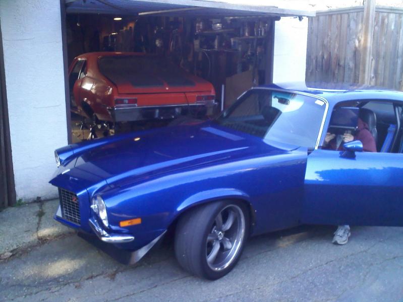
3-28-2012
Well it runs... kindof.
As per internet reading I think I didn't do the proper Write sequence on the PCM, so I started from scratch and did:
1) Write Entire of speed density tune
2) Turn off ignition, turn back on
3) Write Calibrate only
3) Turn off ignition, turn back on and LEAVE it on in Run for 10 minutes
Came back and it fired, and put putted like a sack of ****, idling maybe 350 rpm..
So figuring I'd get rid of all the variables, I loaded the previous stock(ish) MAF tune back on just like the steps above, and started it up and it caught and ran, but idled around 500rpm, and sounded like ****, but it ran. The turbo pipes got hot FAST so I think it was running pretty lean, because I just halfed the fuel pressure (stock 26 lb/hr @ 58 psi vs. my 52 lb/hr @ 43.5psi) for this quickie MAF tune test. Not sure if it was running on all cylinders either because the turbo wasn't spinning all that well, but might be because of the low and inconsistent idle.
SO back to basics. Taking my previous MAF tune and straight up converting it over to speed density and then just changing injector flow values, then will see how that runs and take it from there!
4-1-2012
Happy April Fools day...
4-2-2012
Well the rough tune I had it "idling" too lean at yesterday was using Mark's old 52 lb/hr injectors, which according to the website he bought them off of are rated for 51.8lb/hr @ 43.5 psi, and I set my fuel pressure to 45 psi so entered into HPTuners the data for 50.1 lb/hr injectors (6.31 g/sec). While thinking about it at work today wondering why the hell it was still running so lean, I remembered that in Mark's tune he had the injector flowrate set at 4.91. I thought if I keep my fuel pressure the same then this lower injector value entered would open them more, run richer, possibly make my AFR better. Flashed my yesterday tune with the reduced injector flow values and started it up.. bam... idled right around 780-820rpm with 14.5-15:1 AFR and all. All I can figure is bad injector data on the website but I don't really care anymore.. it's idling good enough to make me happy enough to crack a cold frosty one and sit back for a bit
Haha yea I thought "how cruel could this possibly be if it runs today and then stops working later" but it ran even better after so... guess it wasn't an April Fools joke!
It will be quiet, that's the hope. Want it to be a sensible driver... possibly even something that could pass for having a 307 with restrictive mufflers??
I originally wanted it to look like "an old musclecar that some kid bought and threw rims on" and have all the performance hidden underneath and unsuspecting.. but I think the low stance will be the final straw that throws that out the window haha.
But it actually is pretty loud in the garage because there are no tips on the mufflers yet and it just bounces off the walls. I had the GoPro outside of the case to hopefully catch the sound better but I think it was too loud for the GoPro and it decided to record much less of it. It does have a bit of a mean rasp to it.. standard fair with Flowmaster mufflers I guess. I'll run this exhaust setup over the summer and then later on maybe do a full stainless 3" duals from the y-pipe and and Magnaflows and do over-axle tailpipes to dumps hidden behind/above the rear quarter panel bottoms... that'll guaranteed be a little bit louder :O
4-4-2012
Listen to that idle... ohhh yess
Fun times.. my oil pressure sucks. 20psi cold idle 15 warm idle, spikes up to 25 when revved. New proper-size o-ring on the pickup. The problem can't be too much oil flowing thru the turbo because the compressor has a tough time spooling up at idle, simply isn't getting the oil pressure the journal bearing needs to let the shaft spin nice and easy at idle.
Just pulled the trigger on a Melling high volume oil pump. Do these roadblocks ever freaking stop?
I didn't look at the oiling system no. I replaced the o-ring with a new one and it was a nice snug fit. Oil pickup is about 5/8" off the bottom of the pan if I remember correctly, I wrote it down somewhere. I'll pull the plug above the oil filter tonight and see if I can see the barbell, although I can't imagine why it wouldn't be in there, but I guess you just never know. I've been reading up that if there isn't a barbell in there, engine would get zero pressure.. does that mean that if the barbell has a bad o-ring or seal somehow then it would bleed pressure past it?
I'm fairly confident that the sensor isn't the problem. Engine was reading around 20-30psi with the previous setup, on an Autometer electric gauge. I do have a mechanical gauge I can throw on there if space permits to be sure. Could it be possible that the main bearings are so worn that it's dropping the resistance and thus pressure down that much? I never tore the engine down but now I'm regretting it, probably should've just gone for full build when it was out. Arg.
4-16-2012
Flashed engine with a new tune, idles nice at 675 rpm. Started the engine for about 10seconds to lube the turbo but not long enough for things to really warm up. Blocked off the turbo oil feed line and restarted engine... with the oil still cool and no supply to the turbo it was getting 15psi dropping down to 10psi. ****. Guess oilpan has to come off and investigate the pickup o-ring. Come to think of it I believe I put the brand new o-ring on the pickup tube first, but either way pan's gotta come off.. arg!!!
5-5-2012
Did a compression test today, here are the numbers:
#1 - 190
#2 - 195
#3 - 200
#4 - 200
#5 - 195
#6 - 195
#7 - 205
#8 - 195
The compression tester I had only had a knurled 14mm fitting for the heads so it might've been hand-tightened a bit more in some of the cylinders than others, but overall I'm happy.
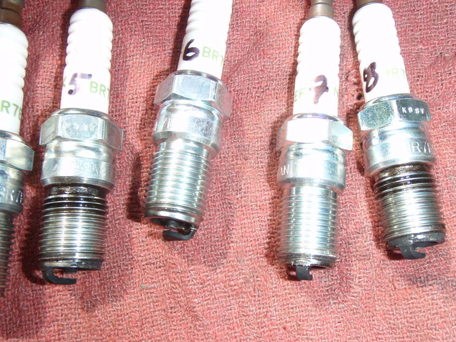
Here are the plugs, what do you guys think?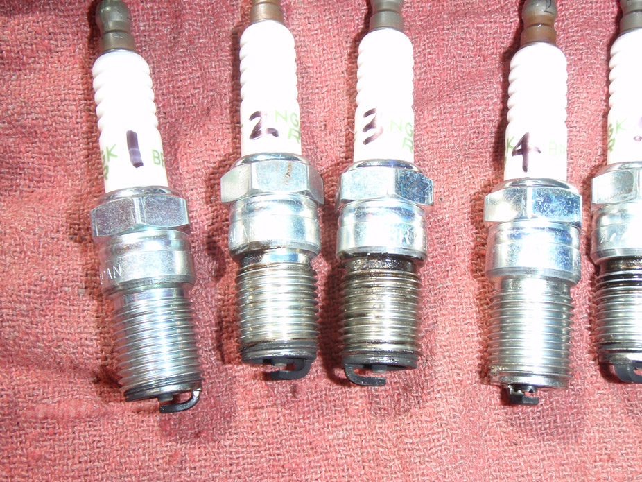
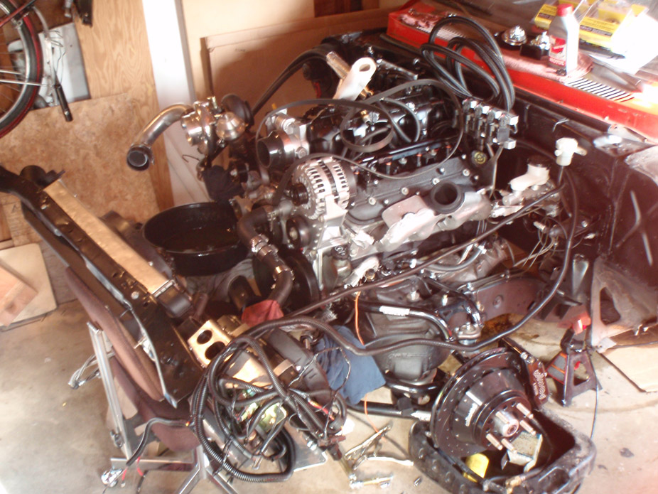
I love working on cars and I'm so lucky that I get to take everything apart again to upgrade the oil pump, and then put it all back together. This is possibly the funnest thing I could be doing to the car right now, I like practicing over and over again.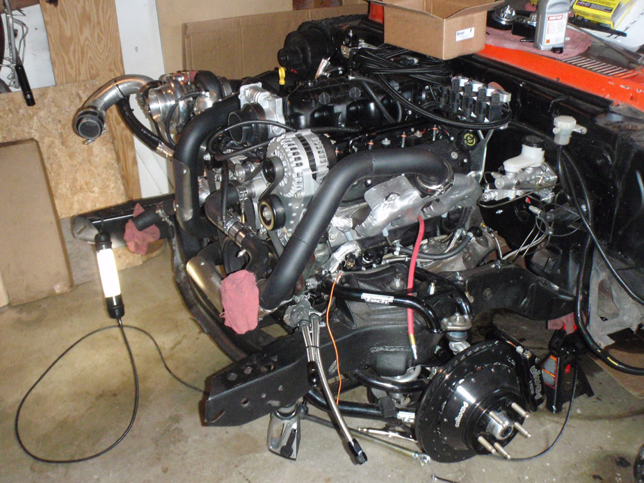
5-16-2012
This piece of **** car won't hold a tune.
Went to start it with new oil pump, would only give the injectors 1 solid pulse and engine would catch and putter out (probably way too rich and flooded cylinders).
Reflashed it with the exact same tune it just had on it.
It stumbled but caught and fired up, was a bit rich at first but then idled nicely for about 10 minutes (injectors pulse about 2-3ms). Fired it up multiple times that day and each time fired immediately after cranking and held nice stable idle with decent oil pressure.
Started it the following day cold and it fired right up, idled perfectly for 10minutes, held good oil pressure.
Fired it up 3 days later and injectors give single HUGE pulse (~90ms) and engine kindof catches, but sounds muddy and putters out (seems too rich). Reflashed and it again fired up, rich at first but then idled out ok.
What the flying shitfuckcockballs is happening? I'm about ready to to throw this ******* car in the trash.
About 35psi cold and 25psi warm with oil that I suspect has some gas in it due to the number of these stupid rich non-start putter out incidents. Re-hooked up the electric oil pressure gauge so I can see the pressure spike as I dab the throttle, which I'll do tonight. All I can figure is the tolerance on the bearings has really opened up due to high mileage. I can't remember what the mileage of the thing was when I got it maybe 5 years ago. Either way if I want better pressure it would likely mean full teardown, so I'm going to drive the ******* thing and throw caution to the wind. That is if I can ever get it to start reliably from one day to the next.
5-17-2012
12+ from battery is hot all the time because with the HPtuners module plugged into only to the OBDII port, the green "connected" light is lit regardless of the position the key is in.
One thing that is curuious that I noticed last night is that the computer does not leave the fans on after shutoff. To test it I specifically set the fan on speed to 40*C and off to 35*C, and runtime to 15seconds, and once the key leaves Run and engine stops, fans shut off. Going to double check my fan relay wiring tonight, but I believe it was relay always hot for source power and 1 side of the switch, and then the relay is activated via switchable ground (from PCM). Only problem I could think is if the power for the switchable ground is also switched so only hot when key is in Run, but I'm pretty sure both relay suuply powers are straight from the battery.
And the MIL light isn't working, even when I test it thru HPtuners, and the wiring is stock Speartech harness, all I did was extend it and made SURE that I kept the polarity the same (I believe it's important for these diode-like LED's?). I'll snip and re-wire it tonight opposite.. maybe the LED was accidently wired in backwards from Speartech.
And I'm getting a VSS circuit voltage DTC, but that's not my biggest problem right now I don't think.
**** just won't end!
This is the BS i'm dealing with.
Long term fuel trims (LTFT's) are disabled.
Running in closed loop.
As the O2 sensors warm up and lean out the STFT's are correspondingly pulling a lot of fuel. This is with an injector flowrate value of 4.90 which I've previously described as being theoretically too small given the injector data from the injector website, however it appeared to work. I wonder if I change the injector flowrates back to the formula-correct 6.32 if the STFT's would lean out much less and there would be less flooding during this weird random initially-too-rich non-catch start. What I really need to do is find out for certain what these injectors actually flow at a given pressure.
Non-catch start (note high injector pulse time in red and orange lines in the 4th window down)...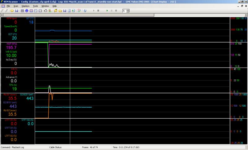
Catching start (initially rich but leans out and idles perfectly at 650rpm and 14.5ish AFR)...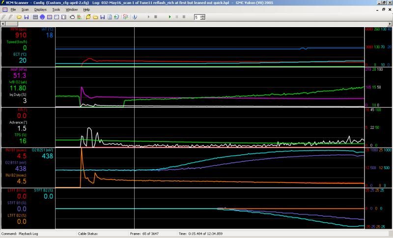
6-13-2012
I got the longer studs from a local performance store, they're just standard 1/2" ARP 3" screw-in studs..
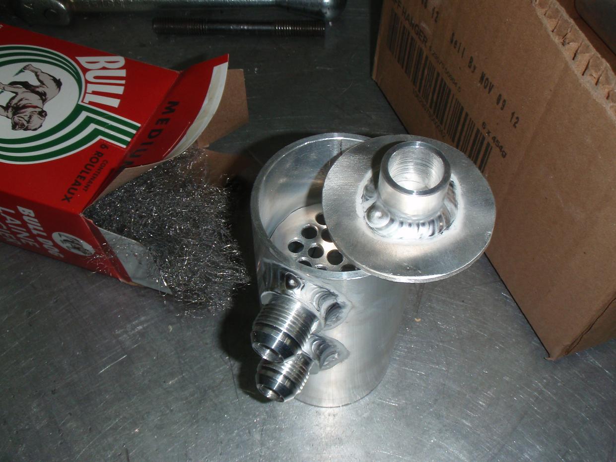
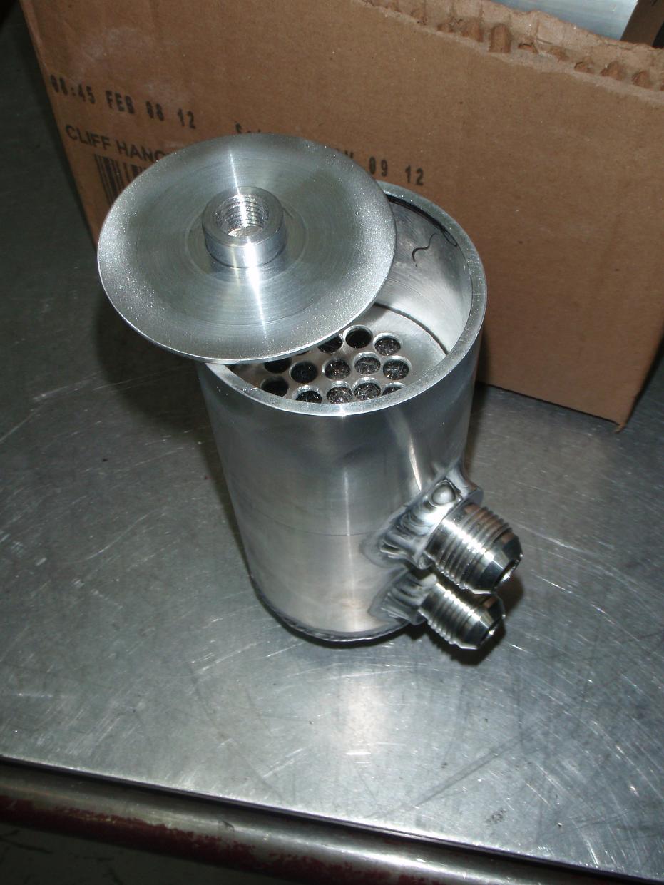
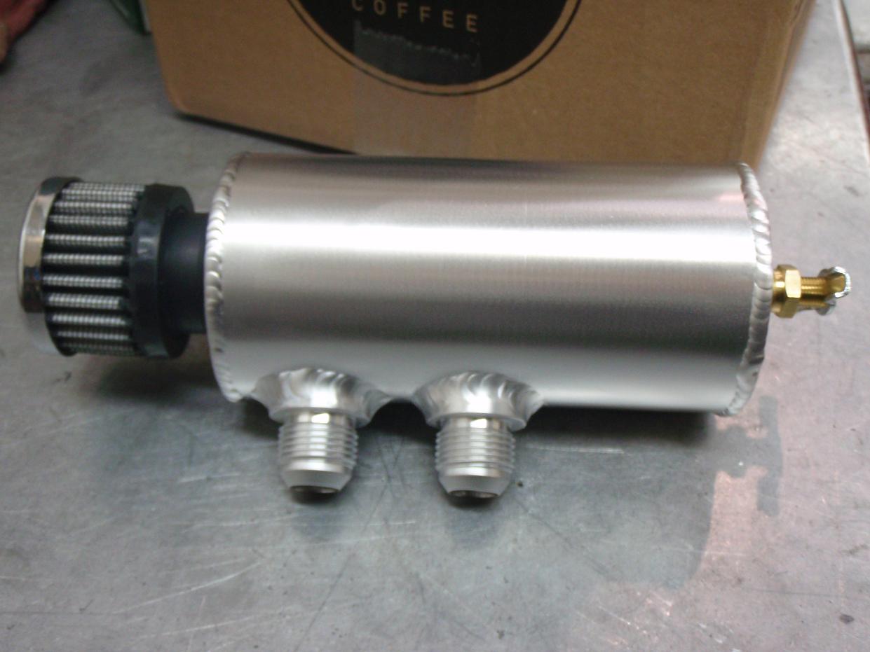
I haven't been working on the car much, just fitting the fenders, hood, need to make some brackets for the hoodpins since the intercooler location doesn't allow a stock hood latch. Made a oil breather/catch can. A line comes from each valve cover and has a seperate "level" of the can, and each level has steel wool trapped in it to hopefully catch oil particles in the air better then let them drop into the bottom, where there's some volume for it to accumulate and a petcock to drain. Might be a bit overkill, or might not even do anything, but at least only took a couple hours to make...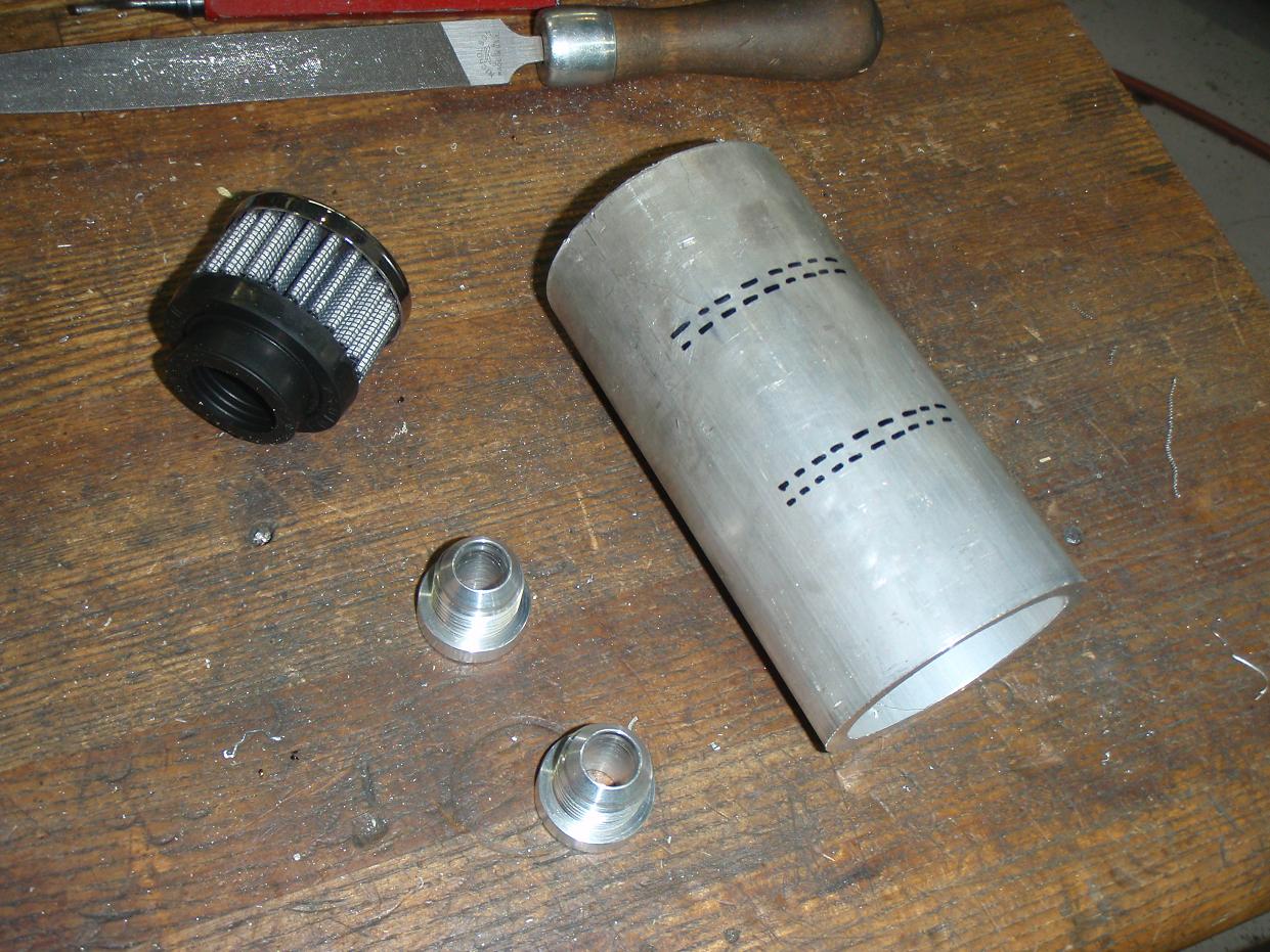
Reducing the wall thickness to make it a bit nicer to weld..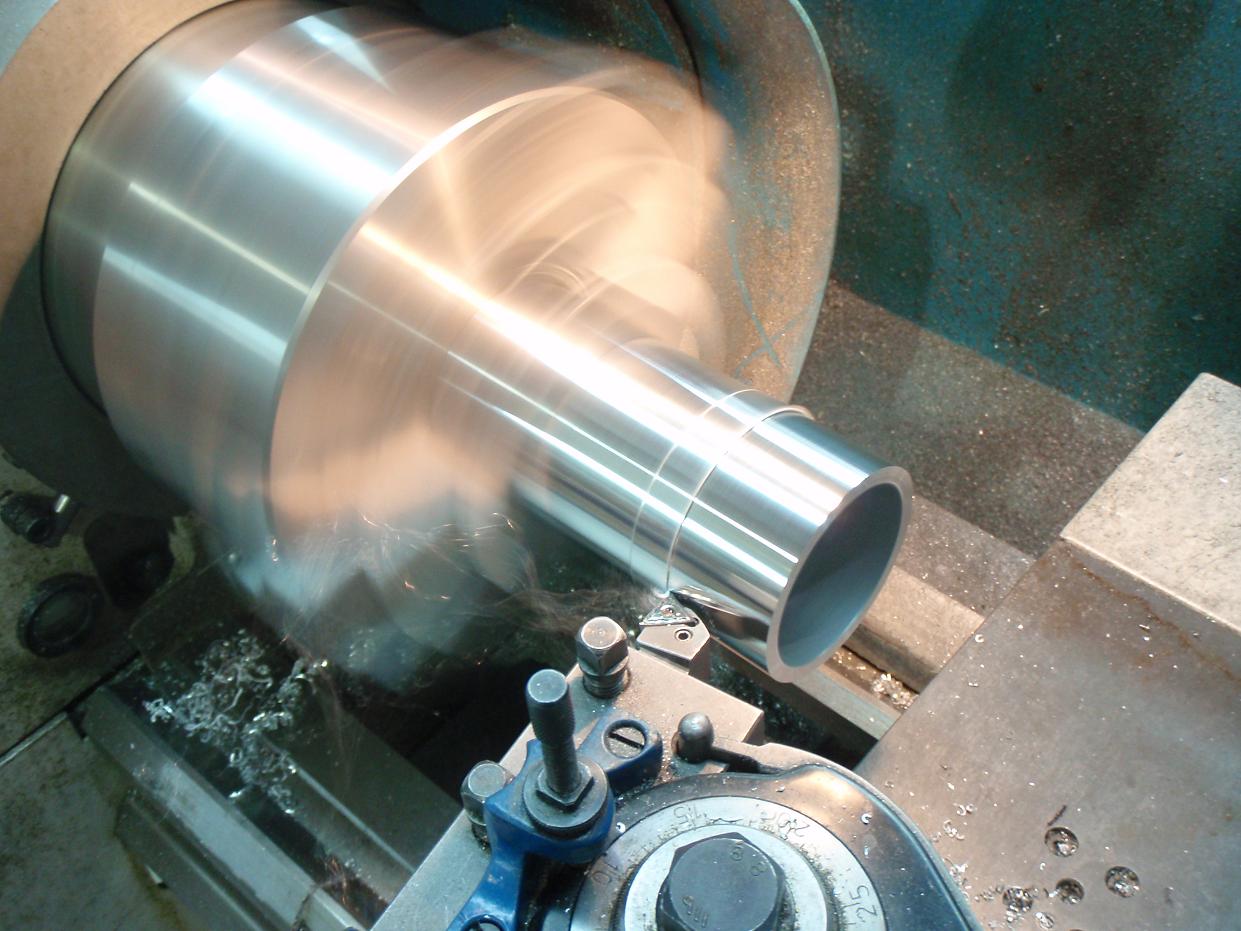
Practicing alum which I hadn't done in months, crossed out bead isn't mine...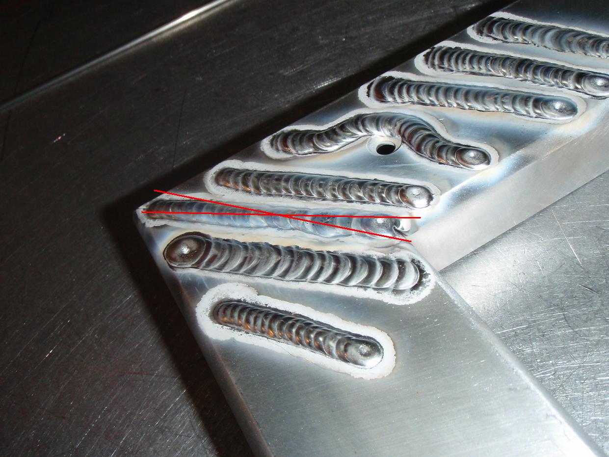
6-18-2012
Good to meet you too Ryan, definitely a gorgeous '69 you have that sits fantastically.
Wrapping up the intercooler piping, also finished the oil breath catch can and need to make hoodpin mounting brackets for the rad support. Then just bleed the brakes and get it on the ground again. Will take more pics tonight.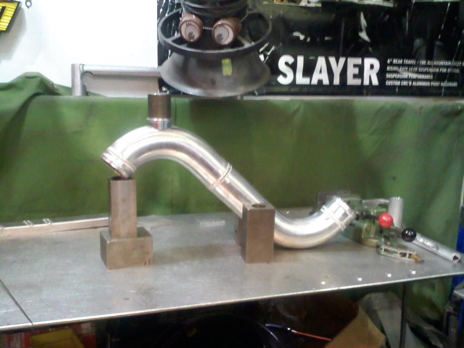
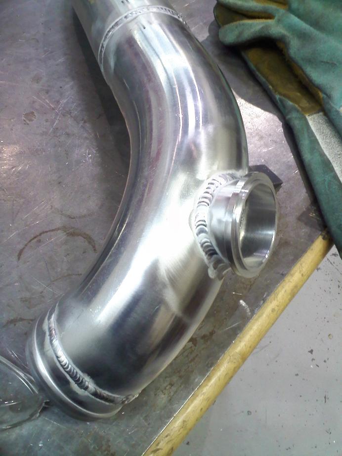
6-22-2012
Getting very close to driving it around, hopefully next weekend! I apologize for the exceptionally shitty quality pics, but oh well.
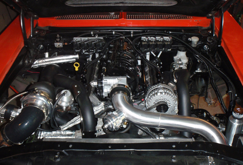
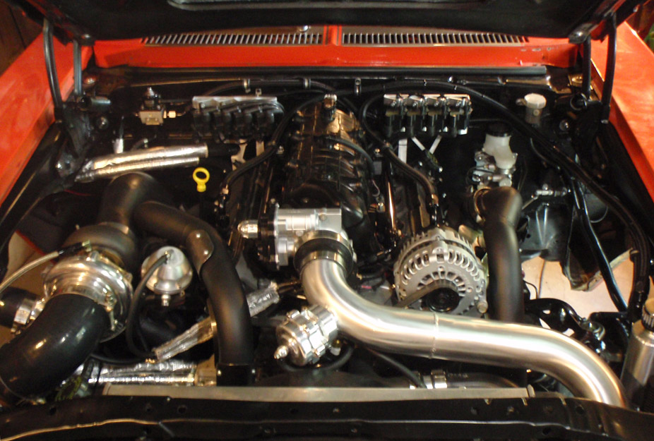
Got the cold-side piping wrapped up from the intercooler to the throttlebody.
IAT sensor is from a Typhoon, is nice and low-profile and has a 3/8" NPT thread on it...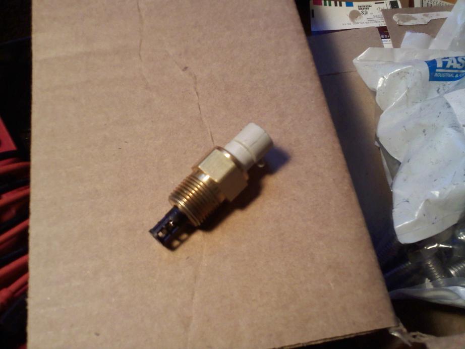
IAT sensor bung is welded on the underside of the tube so it's nice and hidden. Also tacked on some aluminum cable guides from an aluminum mountain bike frame.. something to zip tie the BOV vacuum hose and the IAT sensor wiring so they aren't dangling about and also so I don't have to wrap a huge zip tie all the way around the 3" piping (would look ugly)...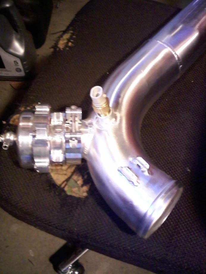
Installed! Minus clamps..
6-24-2012
7-8-2012
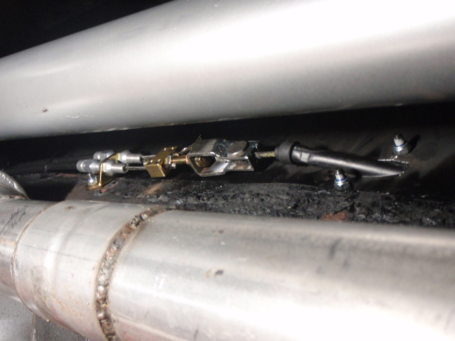
Not much progress recently been tied down at work a lot. Got an ebrake in there and working on installing retracting 3pt seatbelts now but ran out of weld rod so have to wait until next week to get some more.
The ebrake is out of a 240sx, and has a neat mini-cable&housing with a bulkhead stop on it, I think it turned out pretty clean. The clevis and dual-cable stops are from a generic Lokar kit.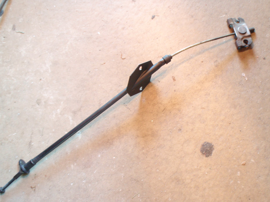
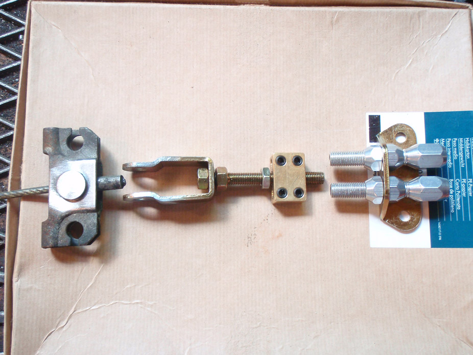
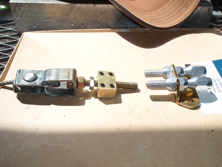
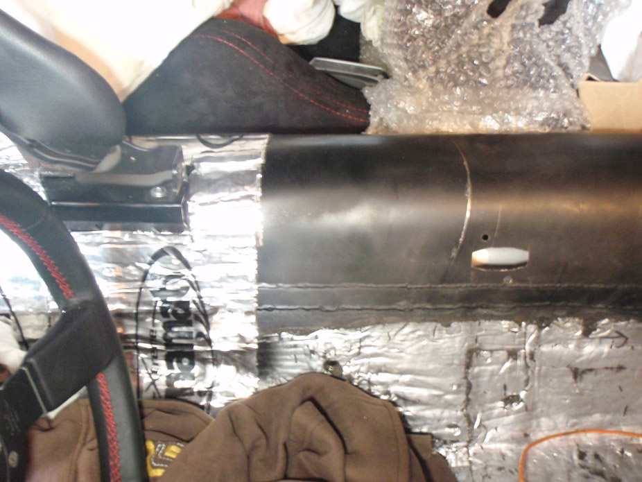
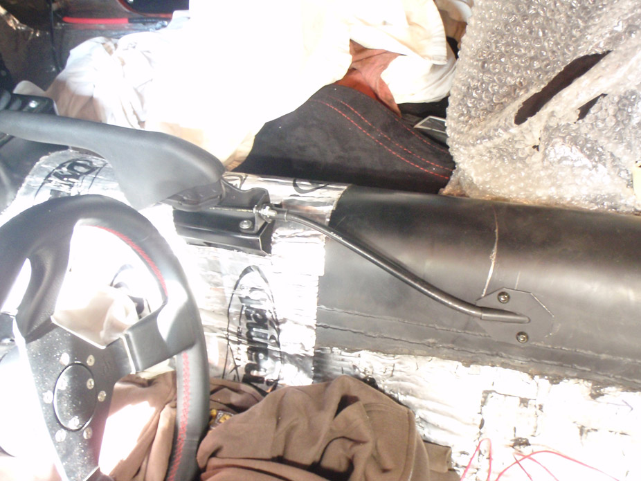
7-15-2012
Safety stuff.. installed some 3pt seatbelts.. no way in hell I was going to drive this thing with lap belts. Belts are from a 240sx, and have a hidden, fixed retractor end..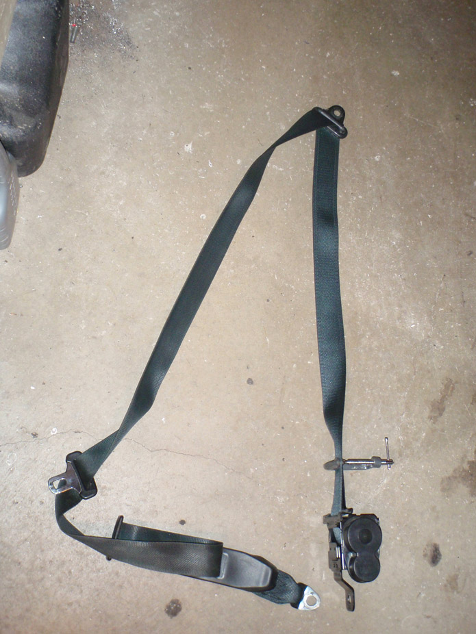
Wanted to keep the hidden-retractor-ness of it all since the interior panels are all flat..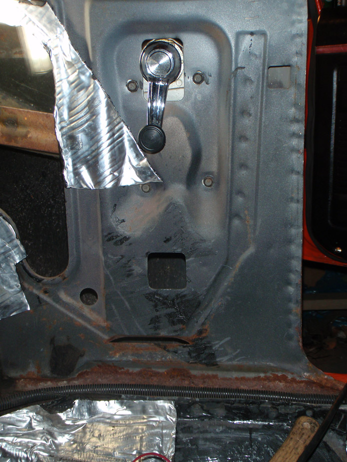
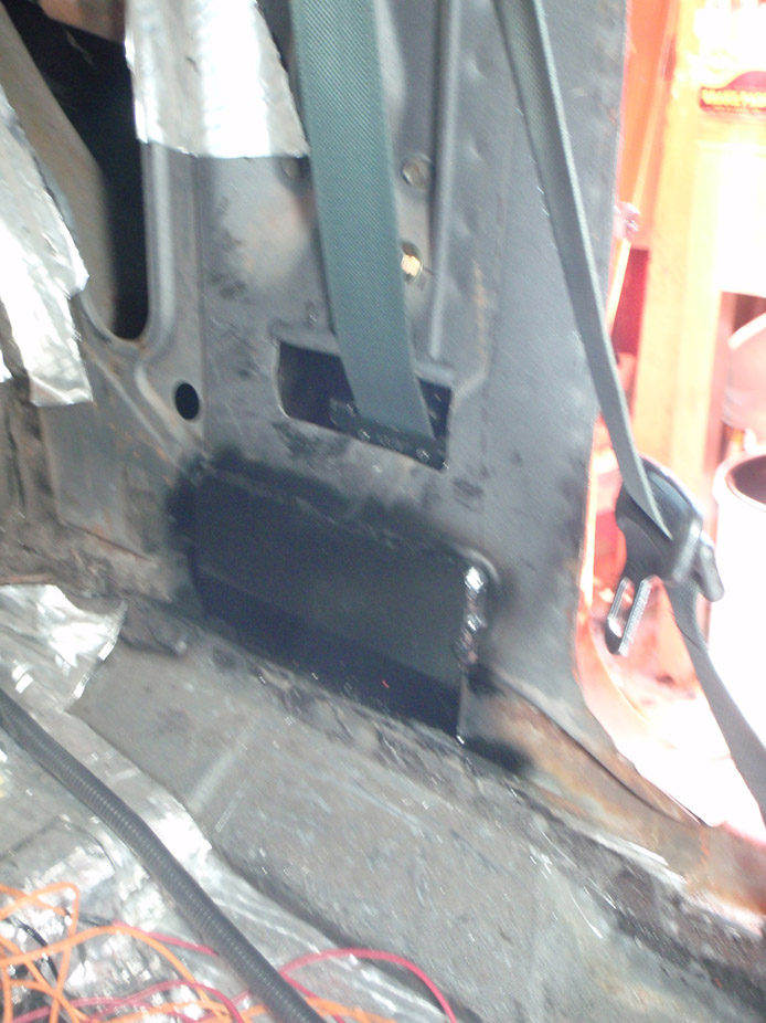
Anchor plate for the base bolt of the retractor. Has a 1/2"-13 threaded boss on the backside of it that I guseseted the **** out of for the retractor to bolt to. It was perimeter welded to the sheetmetal as well as the bottom edge welded to the floor/rocker area.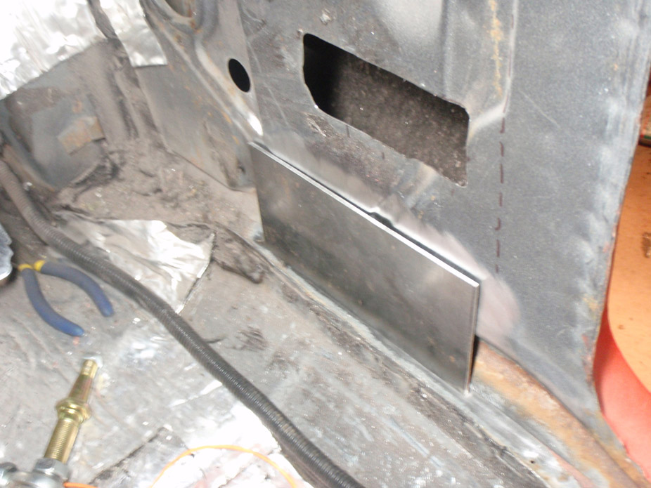
Made this 1/4" plate to locate the should pivot, with the belt installed I put all my body weight into it and it didn't flex or anything, so it should be ok. Template drawing for the plate can be seen here.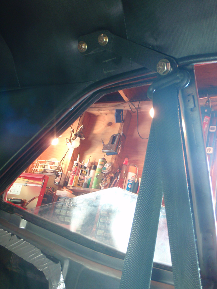
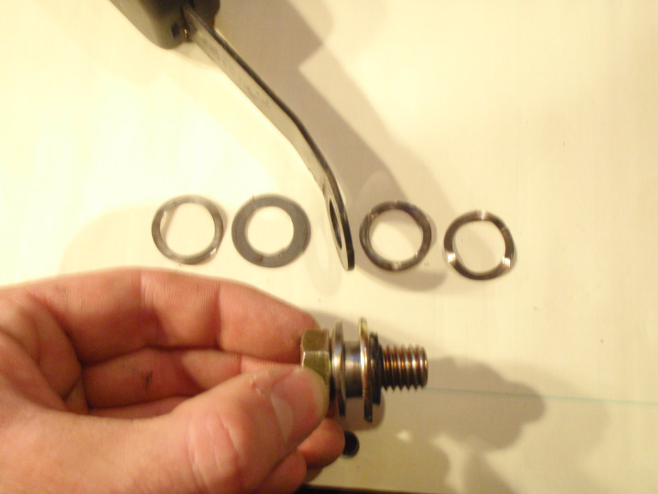
Mostly re-used the 240sx setup for the bolt setup. Has an inner spacer that bottoms out on the driveshaft tunnel when the bolt is torqued down, and has these spring washers so that there is enough preload resistance so that it doesn't fall/rotate, but is still easily movable by hand..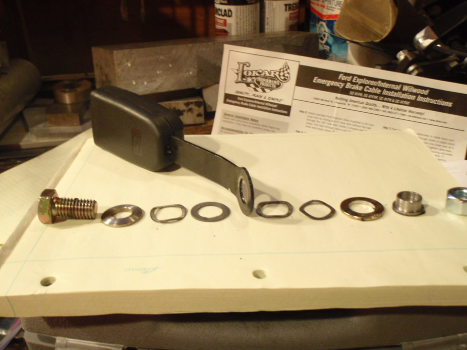
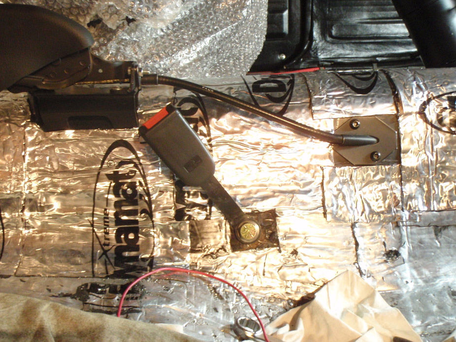
Threw the seat in there quickly and it is nice and snug.. feels confidence-inspiring already.. now just need to do it all over again for passenger side :S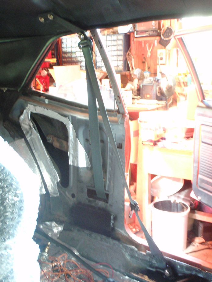
7-12-2012
Wiring update:
When clicking the force-on MIL light button in HPTuners, I can't get it to light up the light.
- PCM is getting good ground as measured at the PCM plug pin
- brown #46 MIL light switchable ground wire is connected to PCM plug
- MIL light is getting +12V
- MIL light illuminates on a 12V bench test setup when wired both ways
I do have some DTC codes that I didn't get rid of and every time the engine has run the light hasn't gone on.. it appears that my PCM simply isn't outputting a ground signal to light the MIL light.
Also, with the proper tach signal wire connected, and even when rigged with the resistor hop-up wiring that is done with Autometer tachs, the tach doesn't register anything. Have yet to check the signal coming from the PCM tach wire while engine is running, but that's next on the list.
This BS along with the inconsistant starts.. could my PCM physically be screwed?
Are there settings in HPTuners to completely turn on or turn off the MIL light or the tach output?
7-21-2012
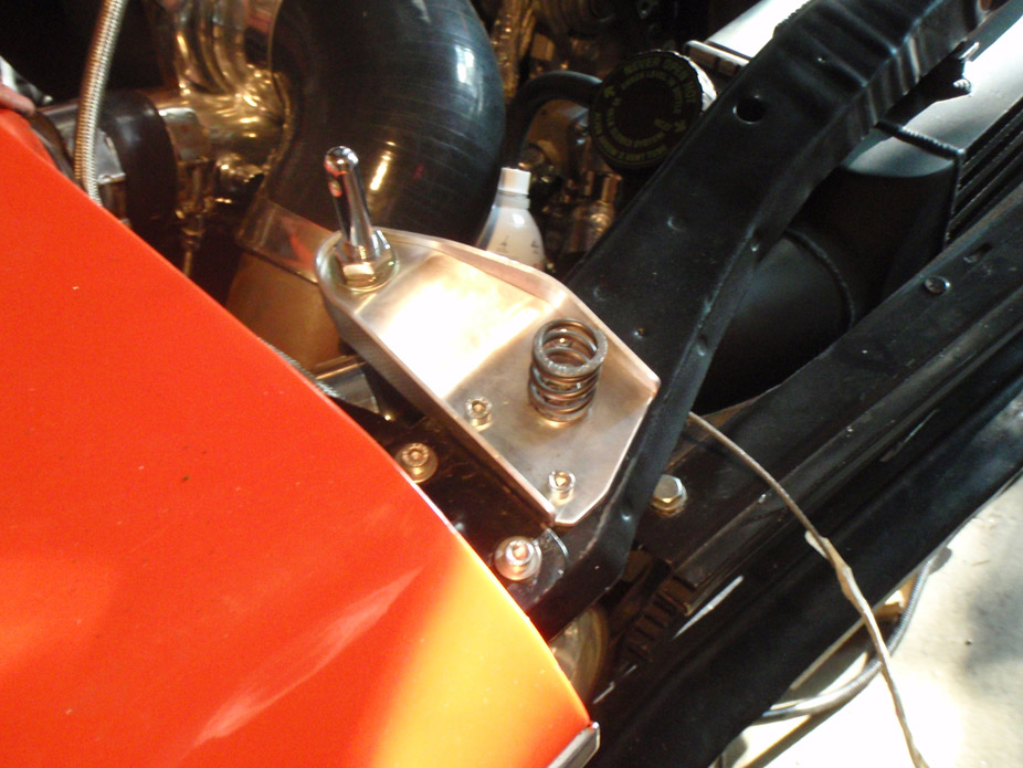
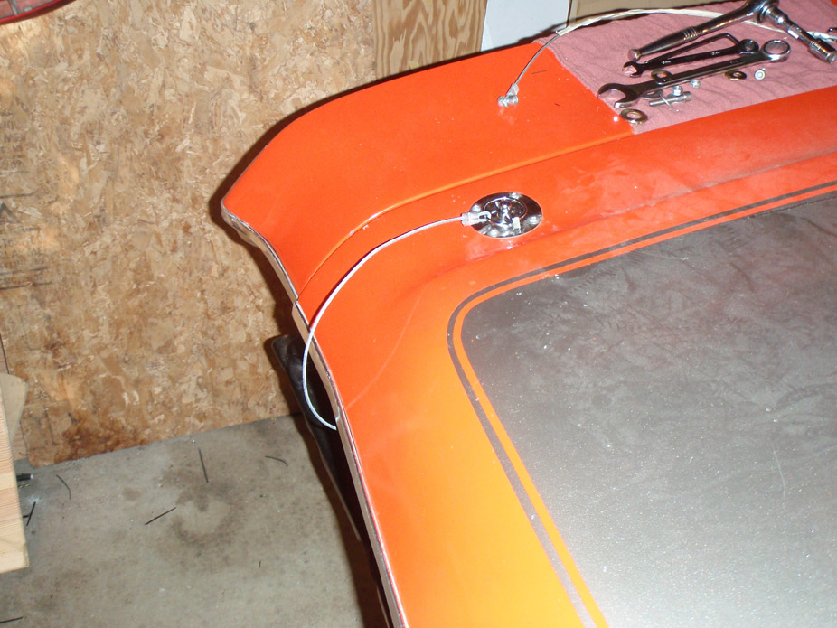
Since the stock hood latch area is consumed by the intercooler, had to figure a hoodpin situation. Ended up using a mountain bike fork spring as a way to preload the hood a bit against the hoodpin to secure it without it rattling around..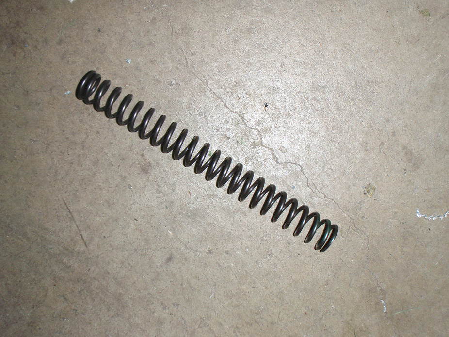
Happens to fit the stock hood rubber bumper height stop perfectly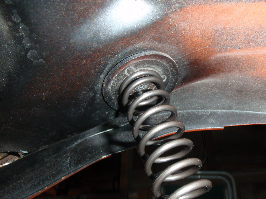
Trimmed and welded a washer to mount them..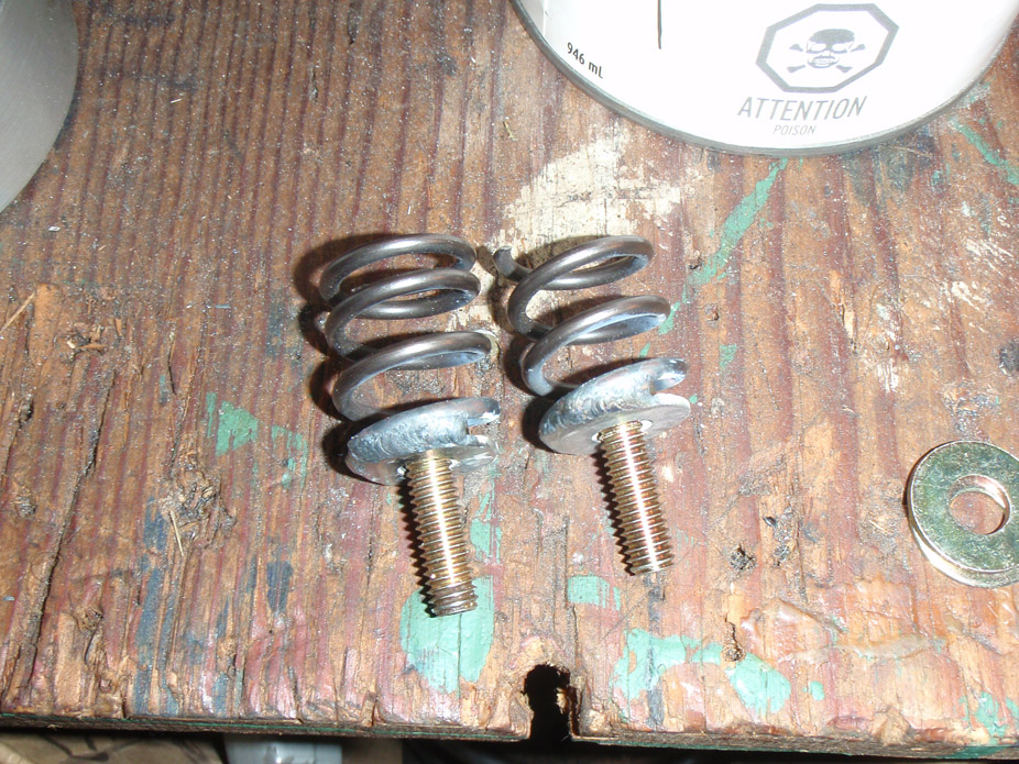
Installed with some aluminum brackets I made for the pins. With the hood closed I yanked up on the hood and was unweighting the suspension.. definitely strong enough..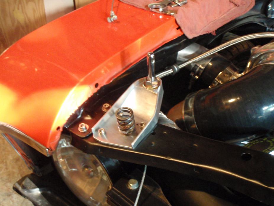
7-22-2012
7-23-2012
Consensus from first drive:
- tires rub a bit near full lock, front has to come up a bit so that when springs sag, front & rear will be right height but level
- car must have some bad bump steer because ride height it has pretty significant toe out, but surprisingly not too darty
- car needs less negative camber and an alignment
- suspensions is firm but takes square-edge bumps very nicely, absorbs but isn't bouncy.. I really look forward to pushing it and seeing how it corners
- engine is a piece of ******* junk. fresh (heavy) oil and it gets 10psi or less oil pressure warm
- loud knocking (guessing rod knock)
- cockpit is perfect: shift location and throw is dead on for my comfort, clutch feels great, good engagement point, brake pedal @ medium-heavy braking is right where gas pedal is for nice rev-matching... all that labour paid off
- VSS signal from computer isn't working either although HPtuners registers the VSS input to it
- didn't push the motor much due to above mentioned **** but in part throttle from 2500-3000 motor pulls as expected but then falls flat on its face, no power.. excessively lean
- once I tried gassing it hard to just say **** it and at 3200 it totally lost all gusto and DBW pedal was unresponsive, AFR gauge spiked 18:1, had slightly high idle and had to shut off, re-flash tune, and restart to get good idle AFR and any throttle response from the pedal.
I think my motor/PCM is haunted.
I'm going forged rotating assembly, engine needs to be rebuilt anyways. I'm figuring I'll do it on an LS2 block while I'm at it.
I'm seriously considering a new PCM, I think this one is physically damaged somehow.
I'm surprisingly not ridiculously pissed about all this ****.. the car itself felt good to drive, just I'm seriously regretting not fully building this engine right from the get-go.
7-29-2012
I'm getting depressingly good at this...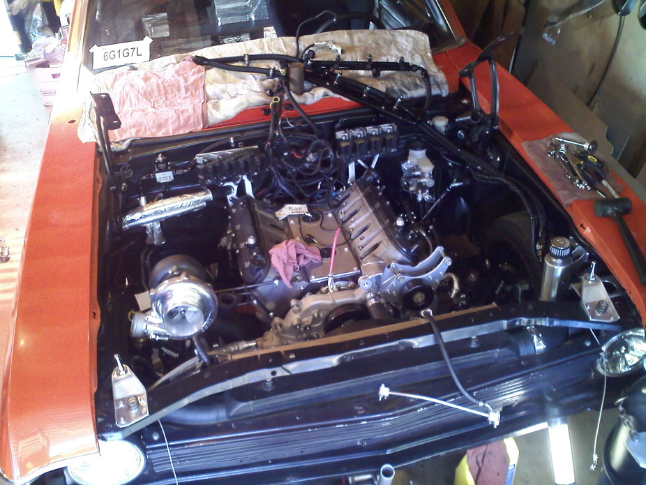
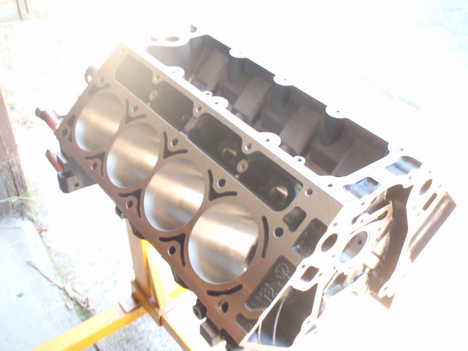
Plan is to keep the iron block (mainly because I have it and upgrading to aluminum is just too expensive and not worth the trouble realistically). Go K1 crank, K1 h-beam rods, Wiseco offset pin pistons. Patriot springs, possibly hardened pushrods, and main/head studs, along with some other gaskets, etc. Looking at a total rebuilt cost of ~$3,000 (reusing block, heads, valves, everything else new) and approx $600 in machining/balancing labour.
First step is to pull the heads off to inspect the cylinders, that'll tell me if I need a 4.005" overbore to clean up the walls or even a 4.010", then order the pistons, tear down the block in the meantime, and we're off to the races.
7-31-2012
Forward progress? I think??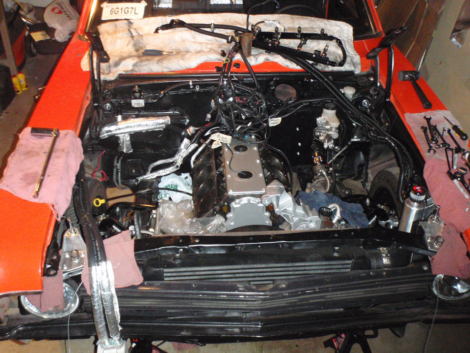
Not very much when you cram all the bits together...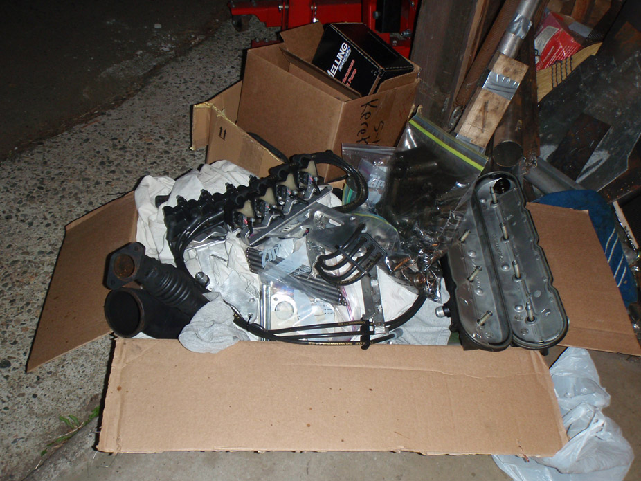
I'm pleasantly surprised with the bores, I honestly can't see them needing more than a 0.005" bore and hone to clean em up.
#1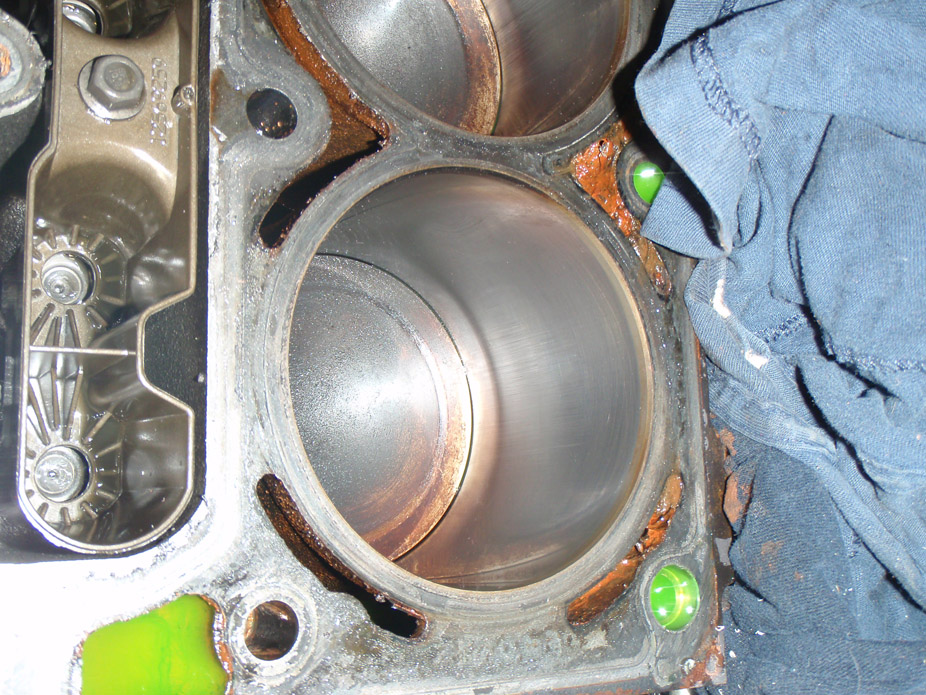
#3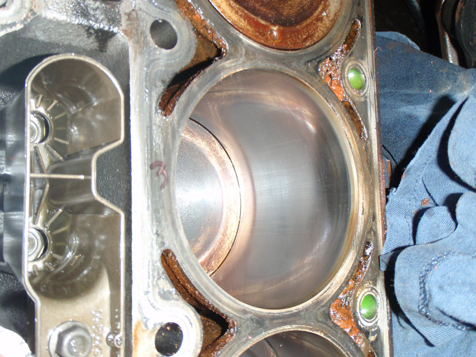
#5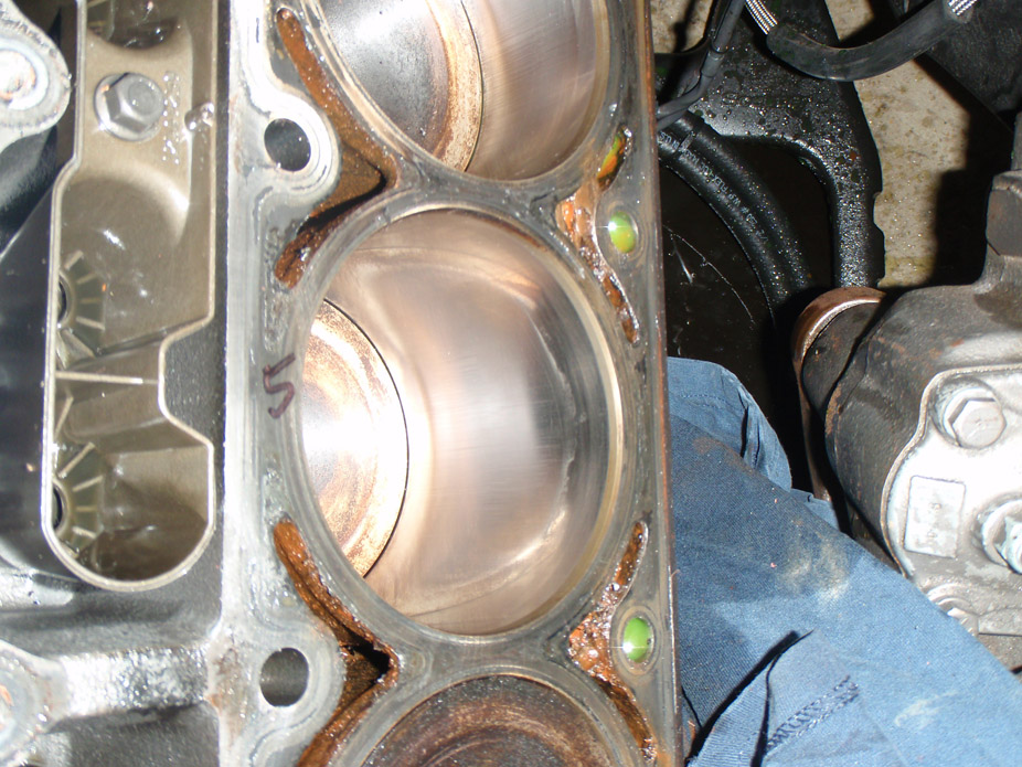
#7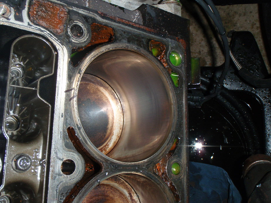
#2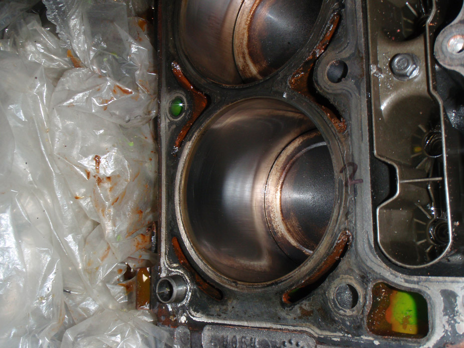
#4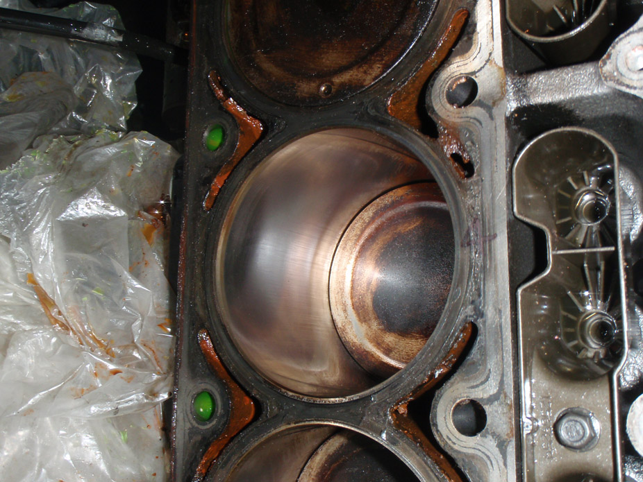
#6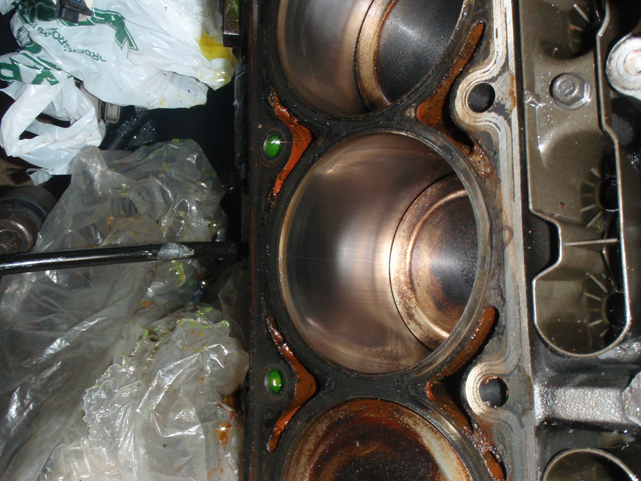
#8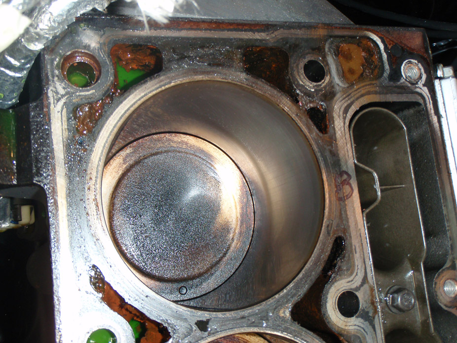
8-10-2012
Parts! Everything except pistons which were drop shipped from Wiseco so still waiting on those, and a couple little gaskets that I'll pick up from a local dealership.
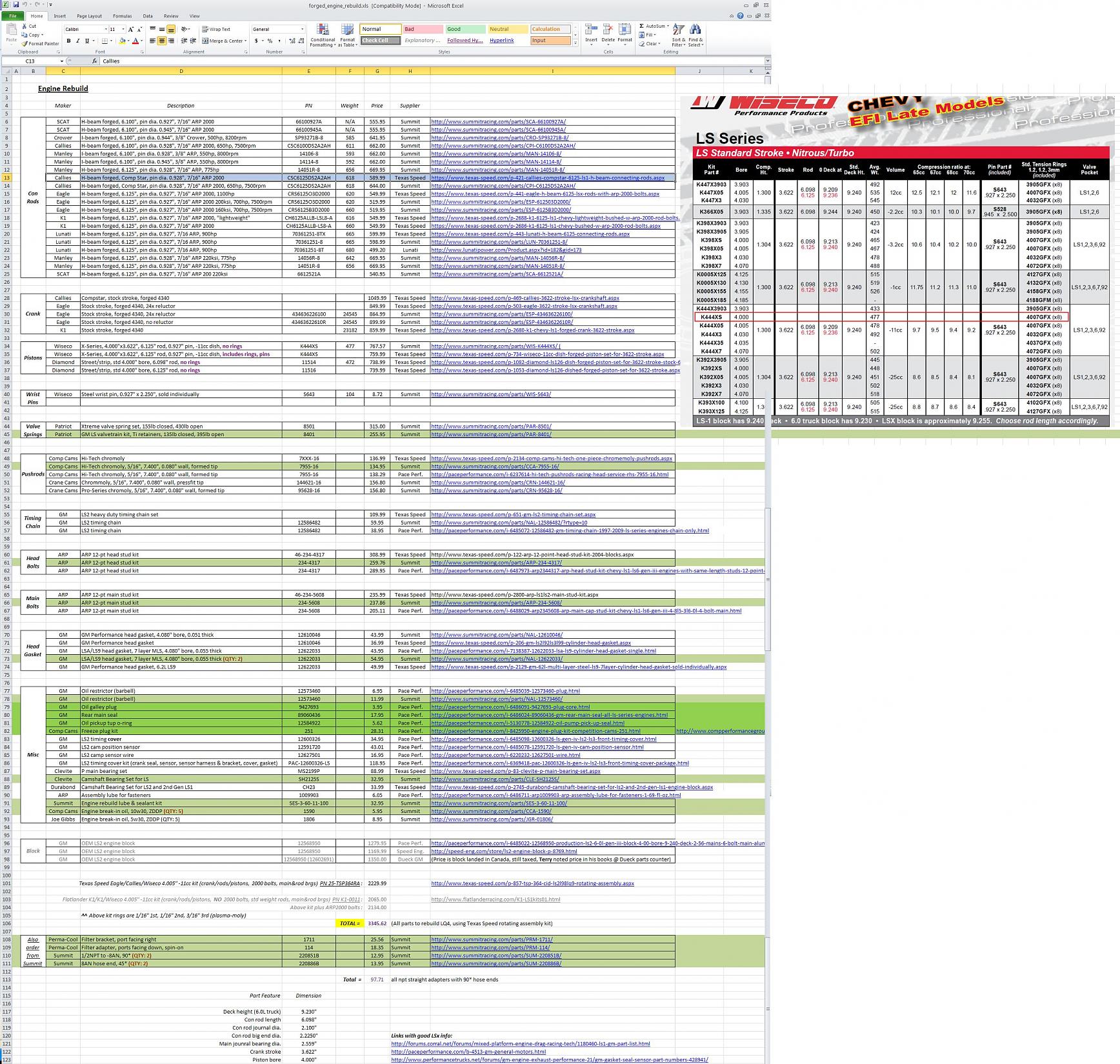
I've attached my Excel master spreadsheet of all the research I've done for pricing on stock-displacement forged rotating assembly, in case anyone is interested.
I really lucked out and Summit had a limited sale on ARP head studs for $259 (down from $309) which is the cheapest I've found them, but appears the sale only lasted a couple days.. guess that was good timing!
Another helpful tip, for almost any GM replacement part, and a limited amount of aftermarket LS stuff, www.PacePerformance.com has the lowest GM parts by far, it's actually pretty crazy.. the cost of all the miscellaneous little plugs and sensors and gaskets can really add up.. so buy from Pace!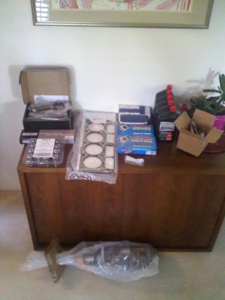
Parts:
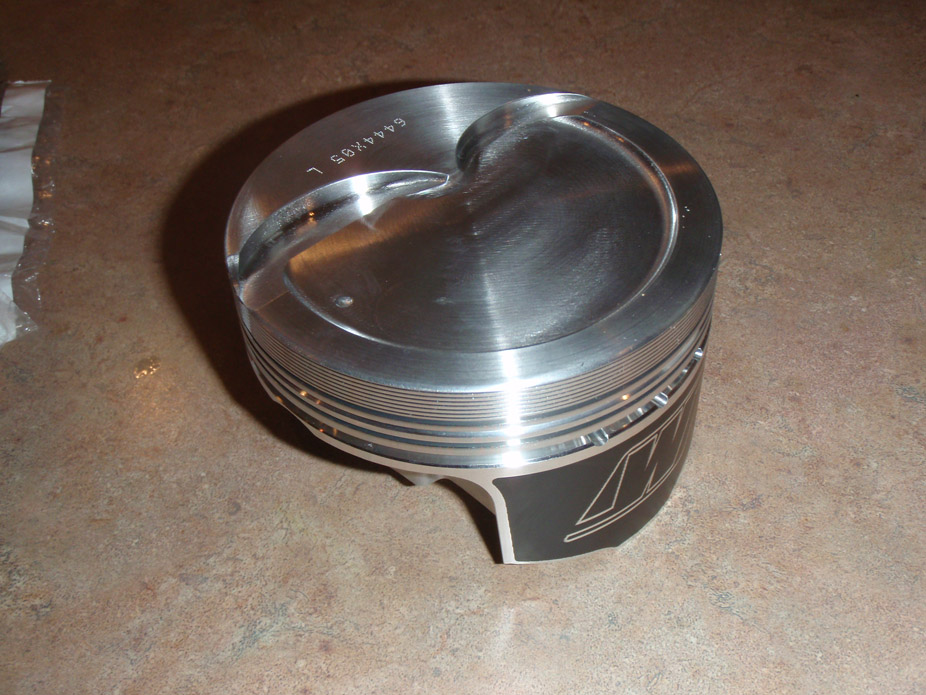
- Texas Speed rotating assembly ($300 savings over buying parts individually): Wiseco 4.005" -11cc pistons, Callies Compstar H-beam con rods, Eagle forged crank, Clevite main&rod bearings
- ARP main & head studs
- LS9 head gaskets
- Patriot Gold springs
- Comp Cams hardened pushrods
- some Comp Cams break-in oil
- engine rebuild lube kit
- assorted gaskets
Total cost in parts to rebuild engine re-using LQ4 block: $3363
Shipping was $12 for Summit & $90 for Texas speed, bringing total parts cost to ~$3465.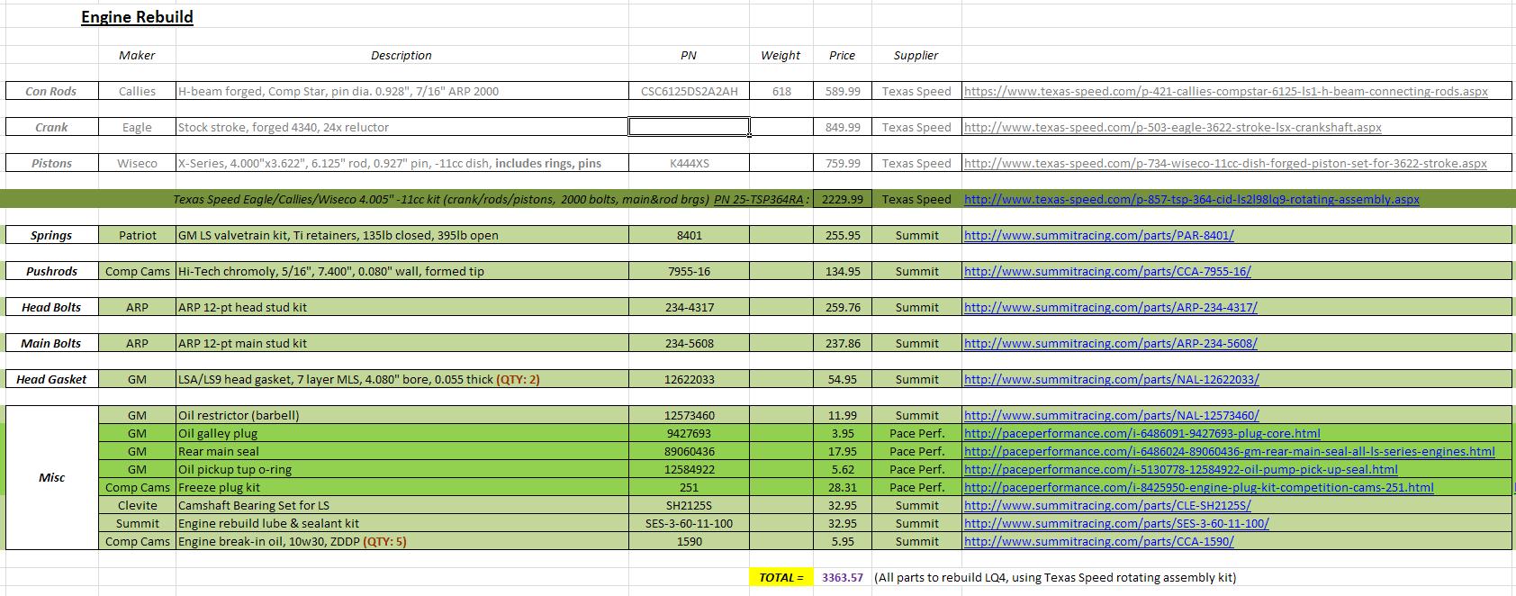
8-19-2012
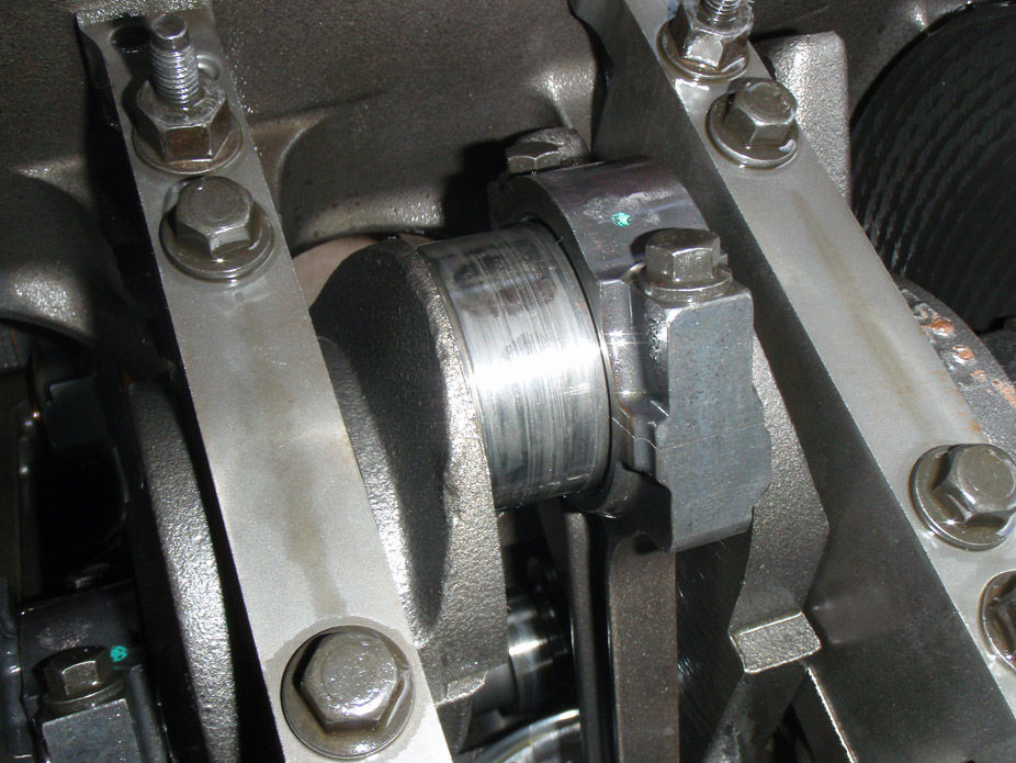
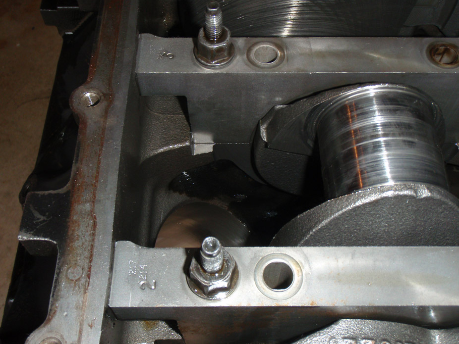
Connecting rods 3, 4 & 5 all had extreme play on the crank, I'd say upwards of 1/16" of rattling around. Upon removing the rods, every single bearing surface on the crank was fucked.
Here is the 1st (and worst) one I pulled, #4...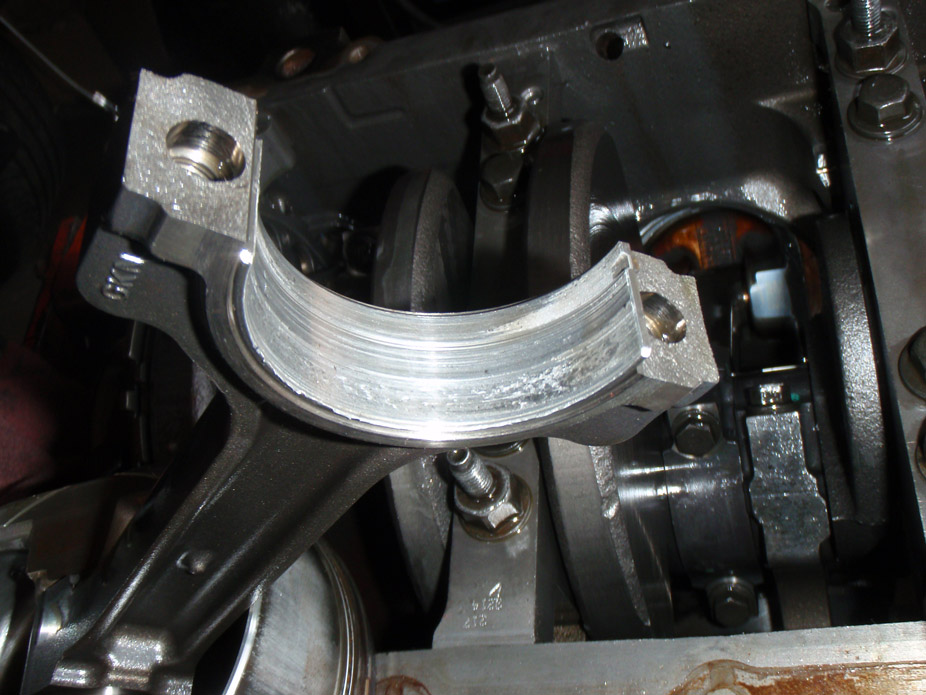
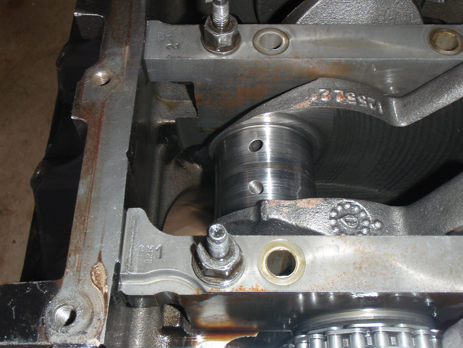
8-21-2012
Well it's official, engine was effed with a capital F..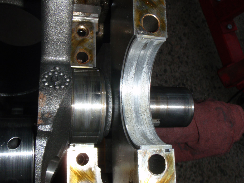
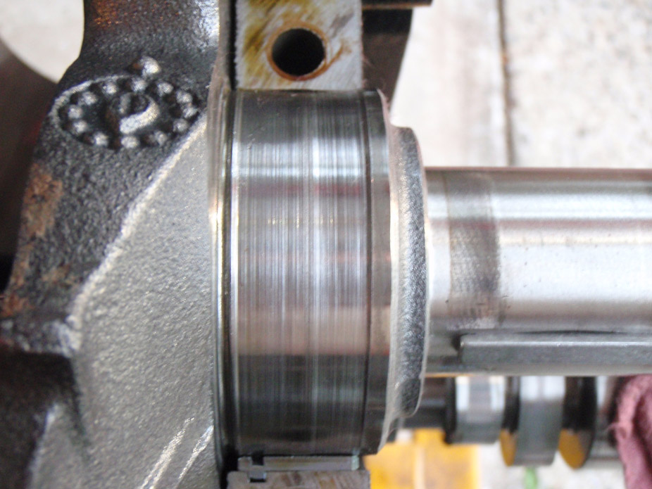
Bottom (bearing cap side) bearing, at hot spot from friction due to lack of oil..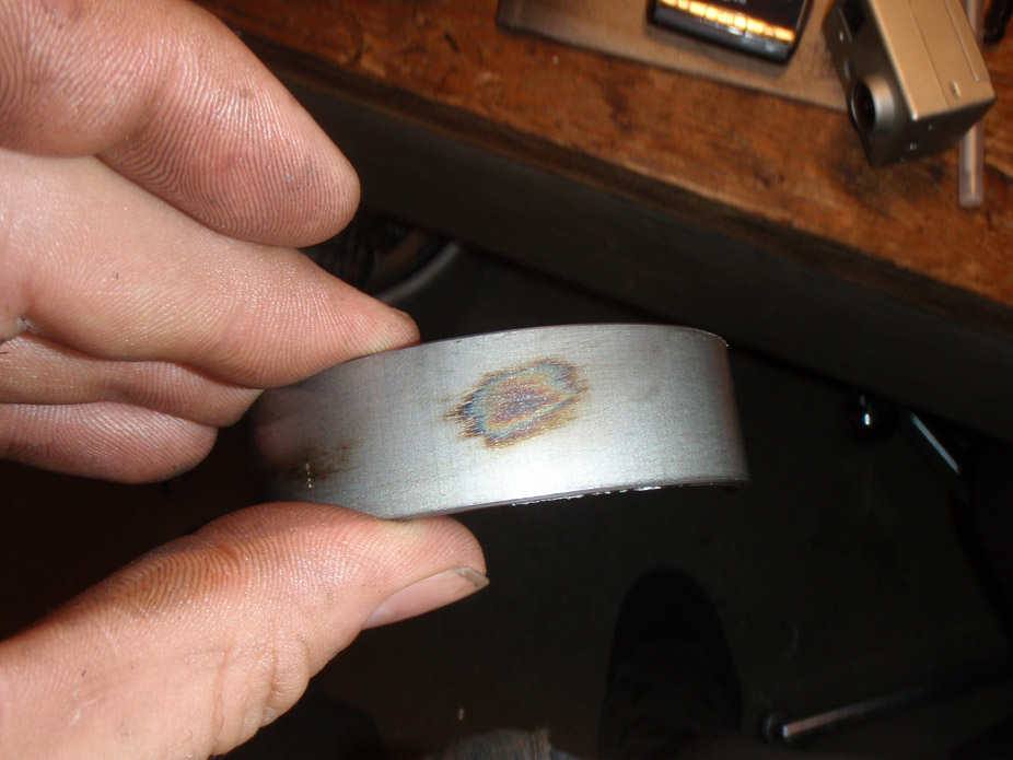
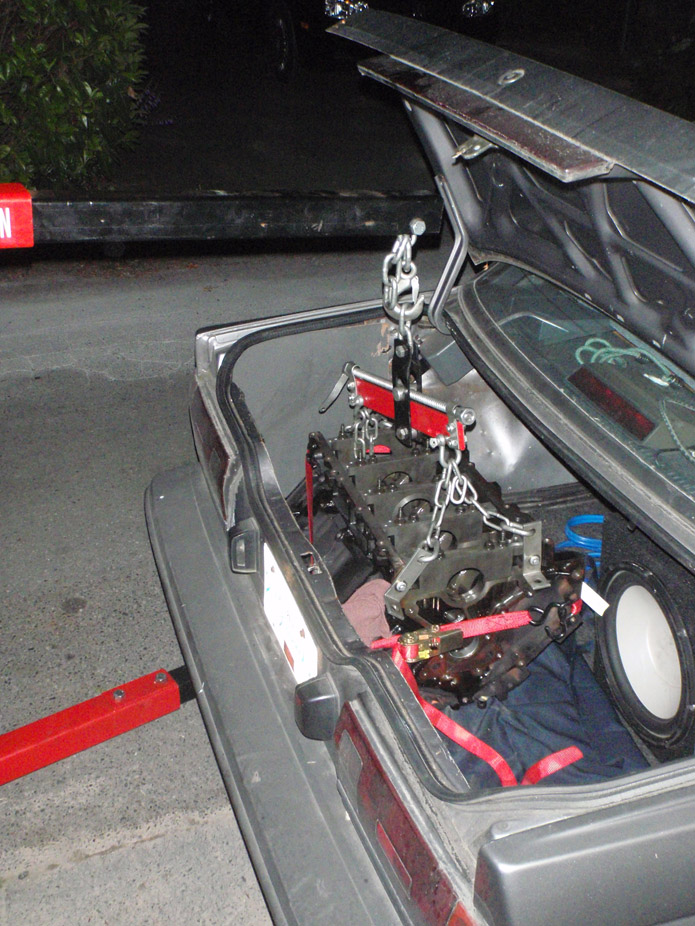
Aaaand block in the back of a Sentra, didn't think it would fit haha..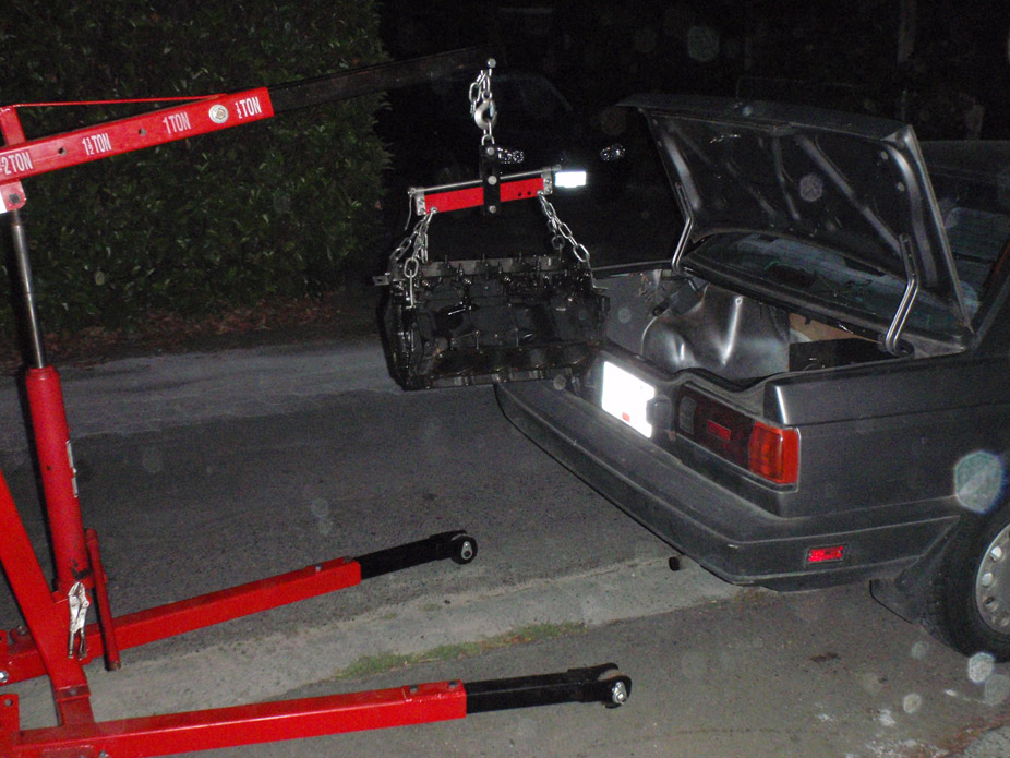
Haha "Manly Mantainium".. that's a nickname that gonna stick around whether he likes it or not.
On a side note, observe the fuckage..
8-22-2010
In my defense, the crank was really REALLY heavy.. could've used Man-hands McGee Marktainium to help lift it, oh well.
Dropped the block off at the machine shop this morning. Place is called Hi-Performance Engines, in Burnaby (for anyone reading local to Vancouver area). Owner of it Dave was super awesome to talk to, extremely knowledgeable, gave me a tour of the shop and explained how every single machine is used for different applications.. I have 100% confidence in these guys and they have a quick estimated turn-around too. If they're good enough for MarkyMantainium's standards then they'll be fine for me too.
Next size of displacement for stroker option would be 402 or 6.6L, so 10% more airflow, which would most definitely max out my single turbo, and there isn't much room for a bigger turbo relative to the hood, wastegate pipe, passenger-side hot pipe, etc. Plus it would certainly require bigger wastegate, needing modification to the pre-WG piping to allow the higher flow. And would definitely require freer-flowing exhaust after the downpipe which I'm not too enthusiastic about making just yet. Also would likely need bigger injectors altho could probably get away with just cranking the fuel pressure on the current 52 lb/hr injectors. Plus keeping it stock 6L will let me get "better fuel economy".. haha.
Man jewellery. These are just too nice to hide inside an engine.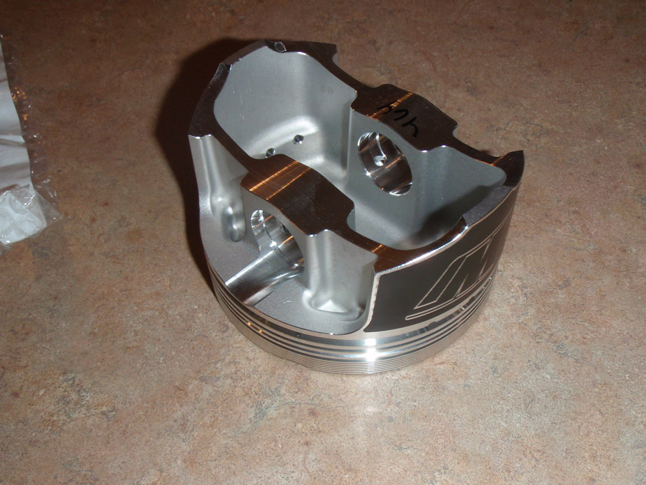
8-24-2012
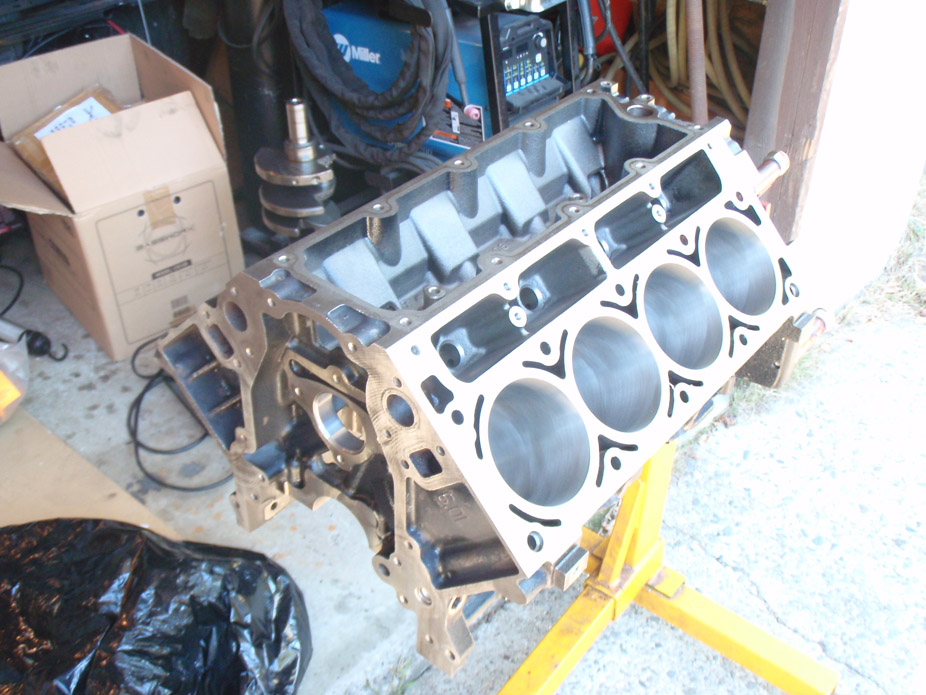
Block has been tanked and cleaned, bores have been checked and 4.005" will be no problem so my gamble of assuming 4.005" pistons would work ended up ok. Align bore with ARP main studs torque checked out A-ok. The deck however is not flat, not perpindicular to each other, and it appears the heads were removed at some point and the deck was "cleaned" with a 3M Sotchbrite and even that can apparently damage the deck and reduce sealing on these MLS gaskets (which are apparently very sensitive to having a perfect deck surface for good sealing). Machine shop estimates that in the neighborhood of 5-6 thou will need to be removed to make everything perfect, and with 0.051" MLS GM head gaskets, that will bump my compression ratio to somewhere around 9.3:1. A bit higher than I was hoping, but still reasonable for medium boost. Looks like I should be able to pick the block up on Tuesday if all goes well.
8-25-2012
The mains checked out fine after torquing the studs. He didn't say how far out it was.. more like "won't be certain how much needs to be removed until we start at the lowest corner on the lowest side and work our way forward, but it should be 3-4 thou, max 5-6 thou".
And yea.. the crank was messed. Super messed. Guess it makes sense where all the oil pressure was disappearing off too
8-30-2012
9-1-2012
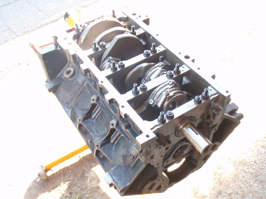
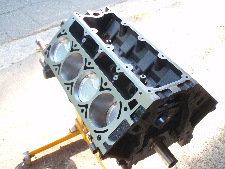
Got short block assembled today. Timing chain, oil pump+pan, lifters, then heads tomorrow. Maybe even clutch/flywheel and start putting it back in..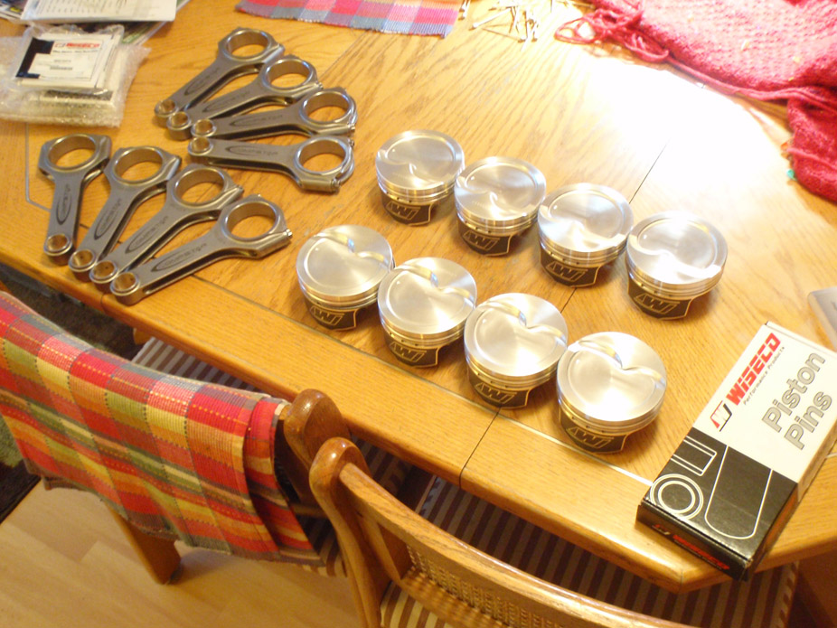
9-2-2012
Hah thanks for the compliment quickkris, but I wouldn't go so far as to say mona lisa. Just a lot of fab work to make it function neatly, and look accordingly industrial.
In other news, it's ready to go back in, just awaiting the return of my engine hoist that i lent to a friend.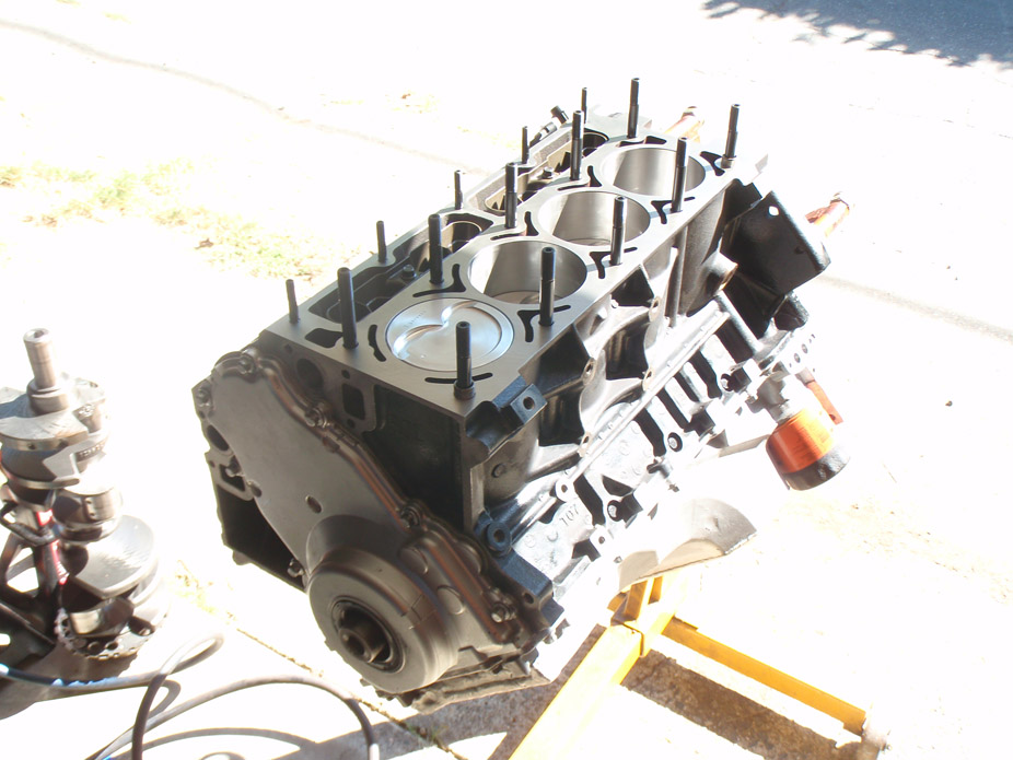
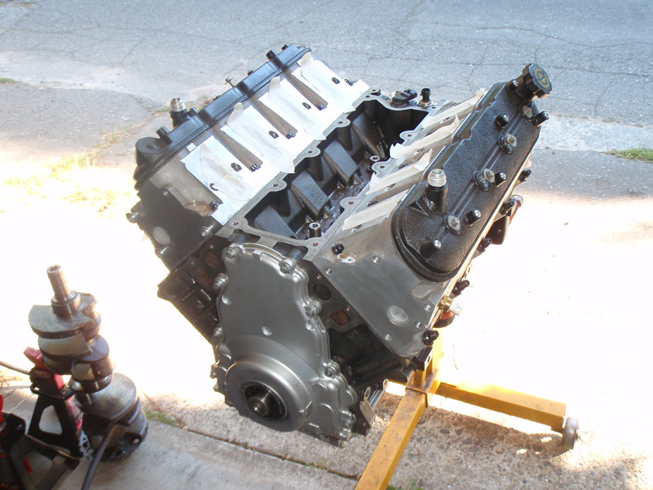
9-6-2012
Drove it tonight. 40psi oil pressure cold idle, 30-35 warm idle. Tune is running crazy rich in part throttle especially under load around 1500-200rpm, like in the 11's or less. Engine also still freaks out if I approach 3,000rpm too quickly and accidentally build boost, shuts down into non-responsive safety mode, still have to hunt and find out why. But oh the glorious sounds as the turbo is spooling 2500-2800 and makes hissy sounds. If I held the pedal at a certain spot and the turbo was spooling just shy or just past 0psi, the acceleration was still pretty awesome.. can't imagine what 7-10psi will be like...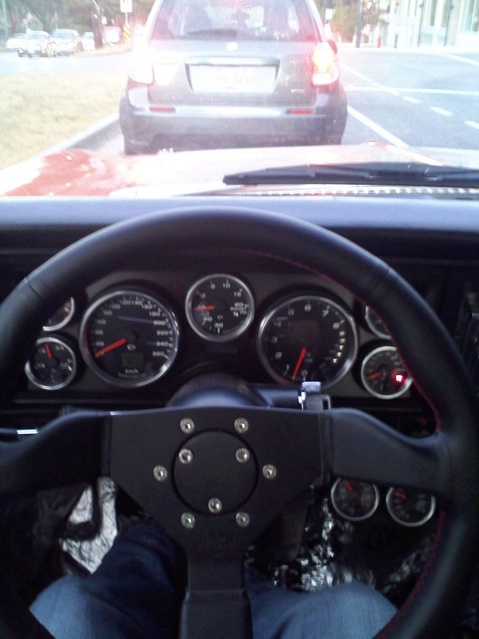
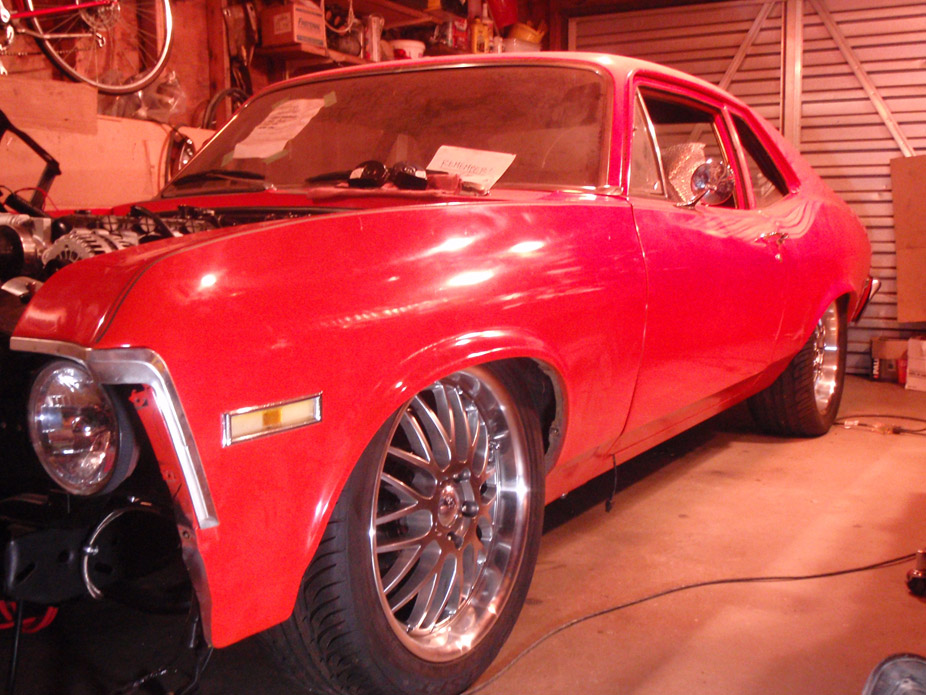
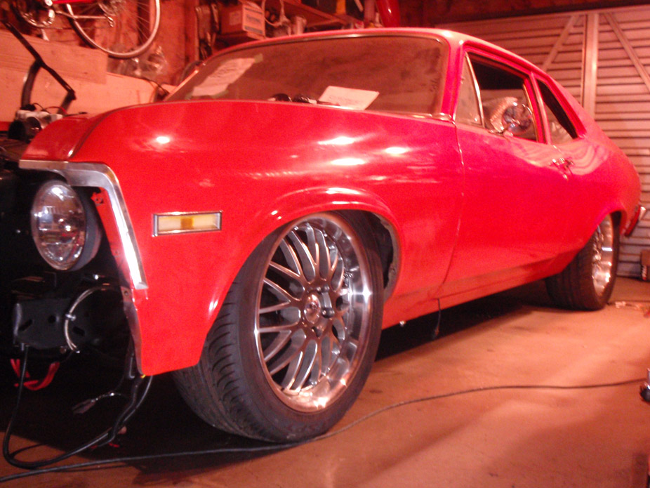
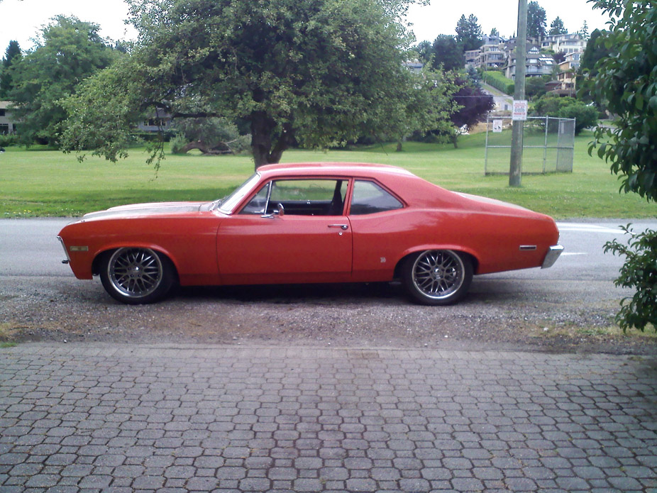
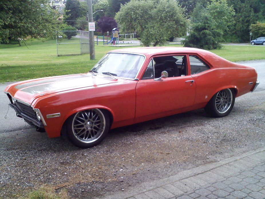
Rear has settled a bit over the couple hours I drove it (after this pic), now sits a bit more level, still have to raise the front maybe 1/2"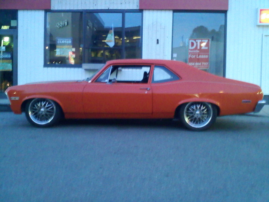
There was some screwup in the parameters table on my HPtuners so the driving I did last night didn't record the wideband AFR or the AFR error. I corrected that and have values now so can start tuning the driveability of part throttle.
I'm running about a 1.5* of camber, maybe closer to 2, but I will knock that back a bit once I raise the front another 1/2" or so. Consider the lowness of the front, and that I haven't trimmed the fender lips at all, the rubbing is very minimal being only at just under full lock. The front tire is a 235 which at full lock is about 1/2" clearance to the subframe rails, so when I eventually plan for wider wheels and a 265 up front, I'll definitely have to notch the rails. Also it has a bit of toe out, I think the car has bump steer although I haven't hit bumps while turning quick enough to notice it yet. I will adjust the toe out myself then once the springs settle a bit more and I adjust the ride height I will get it professionally aligned.
And she starts the daily driver routine..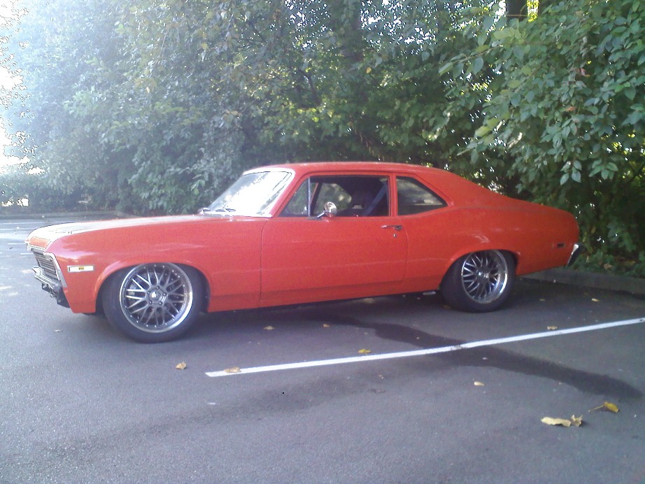
9-8-2012
Been driving it for a couple hours today. My problem with the tune was that no matter what, with or without STFT, it was running way too rich. Tried AFR error tuning it and wasn't getting too far. Then I remembered that Mark's data for these injectors was 6.35g/min or whatever the unit is, and I entered that for the first startup and stuff was way too rich, and then I went to calculate it to verify and for these 52lb/hr injectors at 44psi, I needed the value 5.25 lb/hr and used that to start up again. All this was 1st startup of stock engine way back when.
Anyways, today tried the car with the old 6.35 injector flowrate instead of the 5.25 that I was running rich with... started up and idled 13ish to 14 AFR with no STFT, so that got me close. Then drove for a couple hours AFR tuning and was getting in the 14's mostly for 1500-2500 of 2nd and 3rd gear mostly, trying to shift as little as possible. Then just driving home with ECT at 210ish and IAT at 36ish (slow stop and go traffic) engine went from having no STFT to compensating to up to +40ish % STFT and bogged down to 10ish AFR. STFT was turned off in the tune, and Closed Loop was also turned off in the scanner On/Off section.. why in the sweet **** did STFT suddenly decide to turn on??
In other news, I think I finally nailed the stance . Even considering lack of interior, rear shocks (200ln/in) are too stiff I think, are very rigid in the stiffer "**** settings" and too bouncy in the easier **** settings. Might try some 175in/lb springs and increase the **** damping. Front QA1 conversion coilovers are a bit soft with the iron block and turbo at 450in/lb, I would try 500in/lb and lower the coil ring on the shock body to get right ride height.
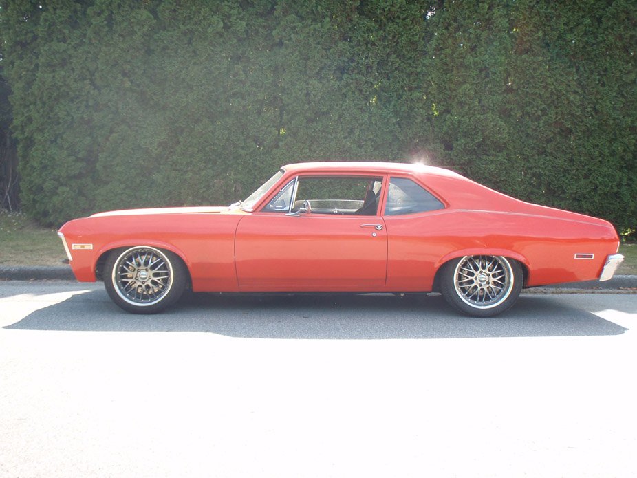
9-9-2012
Hey Greg, the front bumper isn't on because I had to modify the bumper brackets to lower it relative to the subframe (because w/o subframe bushings the subframe went up relative to the front sheetmetal) and I've honestly been too lazy to mock it up to check that my cuts were the right amount. I cut the brackets to also tuck the bumper a bit closer to the car. Mod'd brackets are just tacked together as well. Gonna check it out tomorrow night so I can final mount it, put the running lights in, and have enough resistance in the system to actually have working turn signals.
Very happy with the stance now, and holy **** these Hawk HP pads make a LOT of brake dust, but damn they're stoppy, and with the same level of pedal force as boosted brakes, maybe even less!
Also did about 8hrs of driving and tuning on Saturday and it is running quite well, only very rarely does it blip super rich. It will get stuck in full rich if STFT is on since it appears one of my narrowband O2 sensors is reading way off, and so bank2 immediately goes full compensation rich (25% or upwards of 40%!!) and then bank1 leans out to try and compensate possibly, but only 10-15% lean. Even with STFT switched off in the PCM, it still turns on in the scanner. Maybe I have to do a write entire? Anyways at the beginning of each scan I have to force-Off the Closed Loop and Fuel Trim Learn in the HPTuners scanner On/Off window. *****, oh well at least it's some forward progress.
Oh and then I started getting into boost just for *****, recorded upwards of 6psi.. holy crap.. just keeps pulling...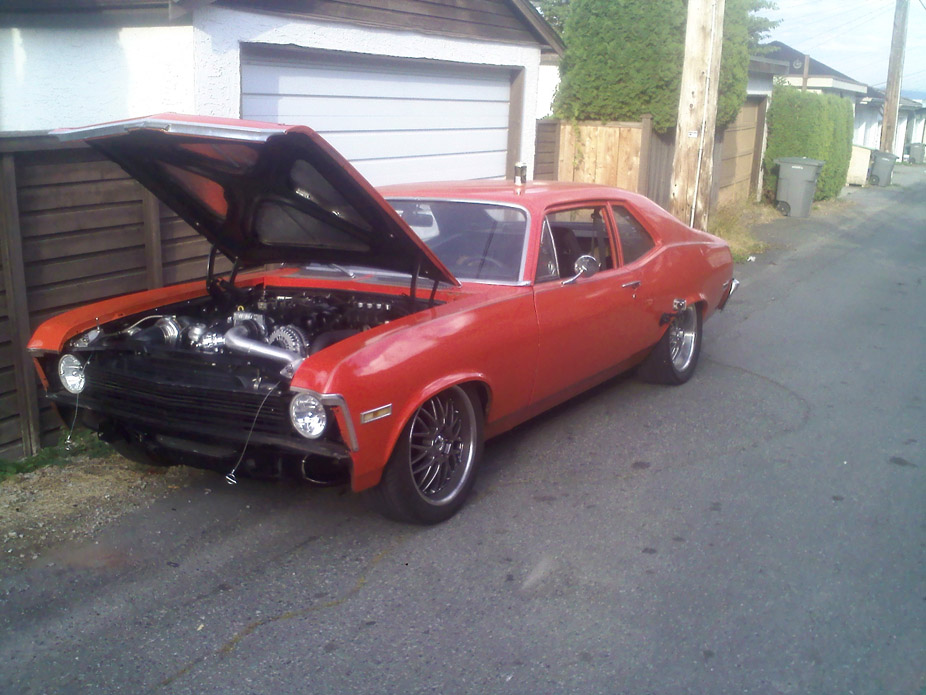
Mark can attest to this better than anyone, but first satisfied smile on my face from this car! So much hard work seems to be finally paying off..
9-13-2012
Well it's official, I've created a monster. Through studious "testing and tuning", it now gets good AFR under boost from 2500-5000rpm, and I'm relieved to know the wastegate isn't undersized as it's cutting that boost off at a steady ~6psi, with no fiddling around from my electronic boost controller yet. It just keeps pulling. It's crazy. The whooooosh is like a jet engine! Best sound ever? My BOV is over sprung a bit I believe. It doesn't open under normal vacuum (good thing) however it makes that annoying studdering compressor surge sound when it vents when I let off the throttle. Mark has a nice consistent "pshhhhhhh" sound, that's what I need to get going.
9-23-2012
9-24-2012
The crank video was the stock 6L setup that kept getting low oil pressure.. I wonder why?? Haha.. good thing I rebuilt the bottom end!
Here is a little clip of the "office space"...
11-6-2012
Ordered Ridetech coilvers front+rear. Also ordered some A-body steering arms and am going to fabricate new inner tie-rod mounting points for the drag link.. a poor man's TruTurn so to speak. Going to order DSE mini tubs real soon, need 305 in the rear, maybe 315. Am also currently calculating material sizing for fabricating a 3-piece front sway bar so that I can run 275's.. which at the same time I am also figuring out the template to use for notching my subframe for 9.5" rim. Also need to think about ordering some mandrel bends to do a legit over-axle tailpipe setup. And so it continues.....
11-7-2012
Tony.. Are you mixing up Mark Stielow's "Red Devil" with the famous but much older "Big Red"?
Red Devil (built about 2 years ago)..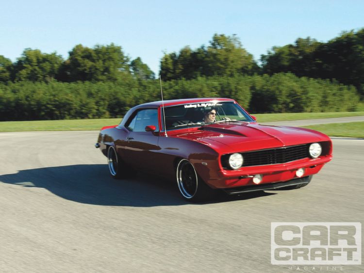
Big Red (built in the 90's)...
Both cars are wicked-awesome in their own right. Big Red for being the pioneering badass pro-touring car way back when, and beating up on all the exotics on the road courses. Red Devil essentially being the modern-day Big Red, with modern car creature comforts and driveability, with brute power and handling that probably nears that of Big Red. I'd happily own either
11-16-2012
Goodies! Also got fronts but they got sent with the wrong springs, so can't mount them for good yet, which is ok because I need to cycle thru the front suspension to measure bumpsteer as well as establish the new droop travel at my desired rim height, since these have a shorter stroke than the QA1 coilovers I previously had. Also got some power steering A-body steering arms which are shorter and don't drop, so am going to cycle thru the suspension and measure bump, and relocate the inner tie rod mounting holes on the drag link to minimize bumpsteer. Will report back later.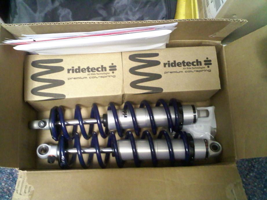
11-19-2012
With the extra weight of an iron block, and the turbo setup, the springs were under-sprung at 450 lb/in, and the rebound clicks were almost maxed-out ( 20ish out of 24 clicks i think?) so a stiffer spring would've been demanding a LOT from the rebound circuit to control. plus in the rear I was also oversprung at 200lb/in i think, so instead of already spending a couple hundy $$ on springs.. just upgrade the shocks w/ closer spring-rate springs at the same tiem. I got a ride in a Nova with single-adjust Ridetech coils front/rear and it was pretty impressive. Same springrates I've ordered and it was the perfect combo of firm for handling yet not overly-harsh for bumps..
For sway bar, I'm going to get 1.25" OD by 0.125" wall mild steel tube, weld 4-bolt flanges on the end, and heat/bend my own 3/8" end plates, making them hug the frame rails as much as possible. This is still up in the air regarding necessity.. first need to mount the tire and mock everything up, and the UCA's are for sure going to be the first & biggest clearance issue. Thinking of selling my standard UCA's and going hi-clearance ones. If I don't, then I have nowhere near the clearance needed, so can kiss turning radius goodbye, which would essentially axe this whole tire-widening project. In the end, I want this to be a no-compromise driver, so turning radius is part of the overall package.
Looking at the TruTurn for a very long time, the steering arms look damn near identical to the A-body steering arms, if not the exact same, altho Ridetech claims they're "made to spec". Also looking at the TruTurn spindles, they are the same variety as the iron 2" drop spindles that are everywhere on ebay, albeit with a 1.75" higher upper ball joint. from much eyeball-engineering, it really looks like the steering arm mount holes are the same between the TruTurn spindles and the other drop spindles, which means that the steering arm holes are kept in the same location relative to the wheel bearing, just moved up the 2" [drop] on the spindle. Since the steering arms also move the outer tie rod end up ~2", and the inner tie rod is moved up ~2" on the drag link, essentially the entire tie rod assembly is simply moved up 2", so it doesn't seem like there's any real crazy length change/angle change, rocketsurgery science behind it. That being said, I still intend on measuring every current link geometry and computing the theoretical camber gain/bump during full droop/bump, to double-check.
Haha I don't have a calibration block for my eyes, but I've been doing a lot of staring, so maybe things are starting to be seen wonky haha.
I already have those tapered studs, and also got a tapered reamer so that I can use nice Moog tie rods for the relocated upper holes. Plan is (pending what some linkage sketching and kinematics reveals) to move inner tie rods up the 2", and the outer tie rod up the difference between my current steeringarms and the new, no-drop A-body ones, which now looks to be about 3". I'll take advantage of this lob-sided height raise on the outboard end to have some up/down wiggle room with those tapered steering studs. The steering arms will also most likely be moved inboard from the wheel about 1/2" due to likely interference with the Wilwood caliper. Due to this, again pending computer stuff, if the bumpsteer is better or worse with the shortened tie rod assembly, then the inner tie rod location will be adjusted up/down/inboard/outboard on the draglink to optimize.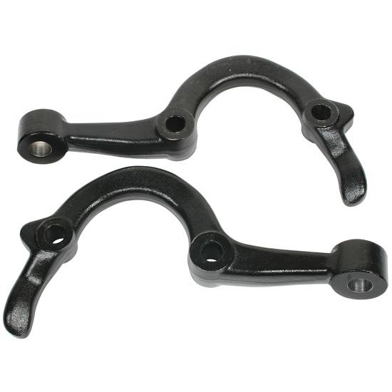

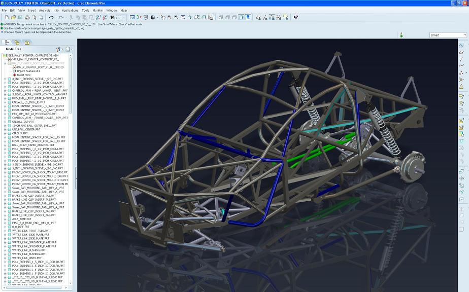
Damn, I downloaded the complete IGES and it doesn't have the engine in it. Would you be able to save the SW engine model you have as an IGES and email to me? I'll PM you my address.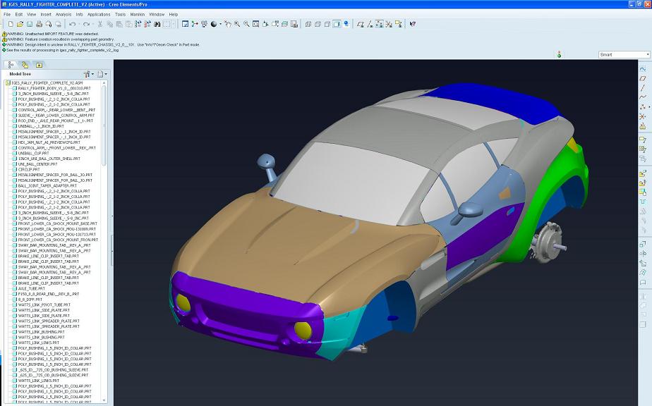
11-20-2012
Haha.. jokes jokes!
On a serious note, this engine model is AWESOME. Now I'm wishing I had it back when I made the turbo setup so I could have every bend and length in the computer!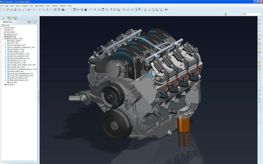
I downloaded the "Complete IGS" @ 179mb, but it was lacking the engine and I imagine a shitload of other stuff. Do you have Solidworks? The SW files would be much more complete (apparently so, since 68wagon's Solidworks Complete model had the LS3) but also obviously much large filesize, since it's a native Solidworks file type and not a compressed universal filetype. Give 68wagon a PM to see if his Dropbox is still working/available for downloading the LS3 IGES file he exported & uploaded for me (thanks again man!!).
11-25-2012
Was bored today so figured I should pay some attention to my car for the first time in over a month.
Couple weeks ago I got in some A-body steering arms to raise the tie rod mounting point, so that I could have more clearance to the rim inner lip, as well as raise it enough so that I could custom-lower it with wiggle room both up and down, not just down, for experimental bump-steering improvement.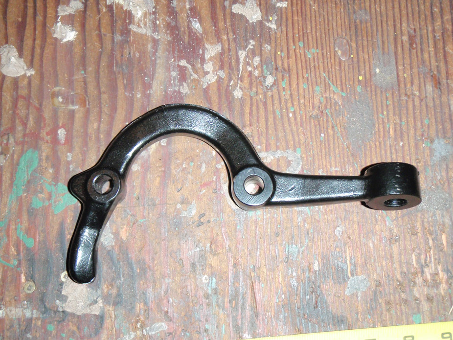
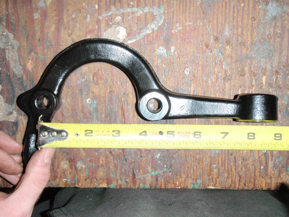
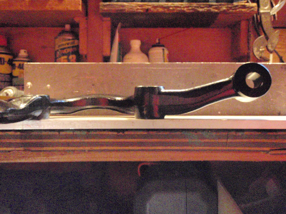
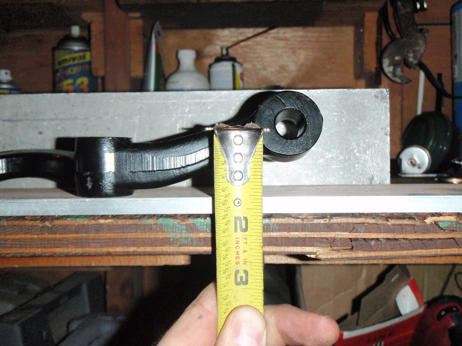
Current clearance of tie rod end to inner rim lip of 18" rim with 4.875" backspace. After looking at it a bit, it appears the tie rod might clear the inner diameter of the rim, but just barely... too close for my comfort plus I want to raise everything to improve bumpsteer.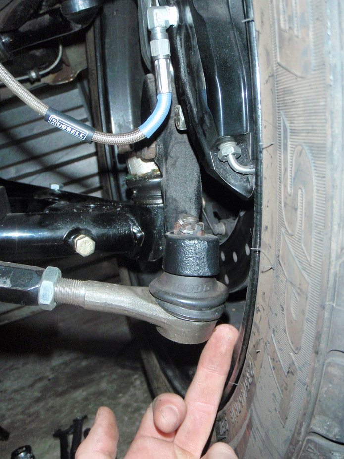
Tons of drop in the stock steering arms..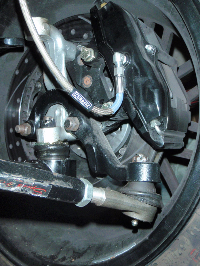
A-body arms raise the tie rod about 3" and look to be a bit shorter too, to quicken the steering. Won't know by how much until I take the stock arms off and compare side-to-side..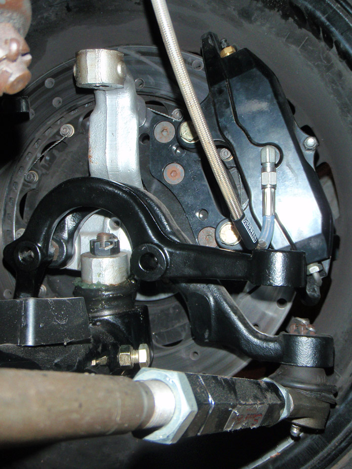
If I choose to leave the stud uncut, it looks to be the same overall length as the stock arm w/ tie rod. I'll design the new tie rod points to be higher up so likely will cut 0.5-1" off the stud to give plenty of rim clearance for the 6" backspace I want to run.
I also won't know if the A-body steering arm will clear the Wilwood caliper until I mount it up. If I can get away with mounting the arm with less than 1/4" of spacers between it and the spindle in order to clear the caliper, then cool. If not, I'll consider heating/bending the steering arms. Will cross that bridge when I get there.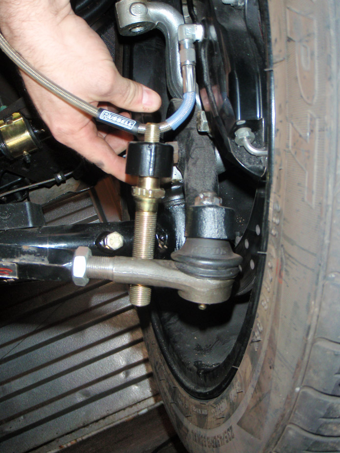
Generic assembly of components that will be cobbled together..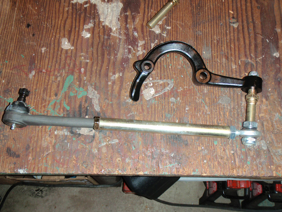
12-15-2012
Picked up the DSE mini-tubs as well as the trunion cross-bar lower mounts for the Rdetech coiloversup front.. Time to measure my current setup's bumpsteer as well as start cutting into the wheeltubs and framerails (I get the next 2weeks off of work).. I predict a lot of beer being needed to work up the courage to make that first cut...
12-20-2012
I am happy with the G-link so far. For me, out of all the 4-link systems out there, the top two (from a behind-the-computer-screen analysis) would be the DSE Quadralink and the CA G-link. Reasons being:
DSE: maintains the NVH ride compliance of rubber bushings without the torsional binding under roll due to DSE's patented Swivel-link (from talking at SEMA, "swivel link" is actually just a "top hat" bushing with the linear bushing part for link twist, and brim of the top hat for handling axial load in the link under brake/accel). Also, a fair bit of sheetmetal trimming and likely seat rear seat structure trimming is needed to install the upper link pockets on the floorpan.
Alston: The G-Link has spherical link pivots, but the nice thing is they're rebuildable and greasable. I believe they have nylon races which could likely be replaced if need be, and being rebuildable is nice as grease will over time attract road grime, etc. The G-link has a great degree of freedom for roll, which would make tuning a rear sway bar nicer, as well as better bump compliance under hard cornering/roll. Nice to have multiple link mountnig holes for tuning anti-squat, as well as length-adjustable links both upper & lower for adjusting wheel position and pinion angle. Major downside of this system is the upper link pockets aren't tied together to spread the loads between framerails, but I fixed that.
Other popular systems..
CA G-Bar/Ridetech 4-link: Simple, very cost-effective system for what you get. Adjustable ride height with adjustable upper links but non-adjustable lower links. Rubber bushings everywhere (at least on the cheapest setup, heim joints are an optional upgrade) so some bind will occur. Upper link pockets are reinforced side-to-side which is nice, as well as it being a true bolt-in system.
Speedtech torque arm: Good price, added weight of the torque arm (at least in the 1st generation of the Speedtech torque arm without milled windows in side plates on the arm), however they seem to have a bushing'd link setup called the ArticuLink, similar to the DSE's Swivel Link.
BMR torque arm: See above for Speedtech, minus the articulating link.
Total Cost Involved: Another torque arm, fairly inexpensive. Claims to be 100% bolt in but from looking at the pictures, the forward lower link pockets appear to be pretty bulky, not sure how they'd fit around the stock framerails as bolt-on only. I have no opinion on ride height or install as I didn't look into it much at all.
Heidt's 4-link: not sure how popular, but another bolt-in 4-link. Have no opinion on this one either as I never really considered it seriously.
Lateral Dynamics 3-link: Not sure if this is still produced, but was a very nice, well-engineered system, unfortunately (but unavoidably) the upper link's forward pocket took up a lot of area in the rear seat so you have to go either sans seat or make a custom 2-bucket setup.
Generic Art Morrison 3-link or 4-link: These are both real nice pieces, but only for those that are seriously chopping up their car and removing a ton of sheetmetal, and love the braindamage of doing so much fabrication. Also has the same style of link pivots as the G-link, but developed by Currie and named "Johnny Joint".. essentially a bigger version of the rebuildable spherical rod end from Alston.
One side comment.. I'm still wary of systems that use a rubber bushing in the link, but also that the link is adjustable and so is threaded with a jam nut. I fear over time the roll in the system and the relatively-not-super-forgiving rubber bushings will rotate the bushing housing end of the link and work the jam nut loose.
I should say that roll for all these applications should normally be 1-2degrees or less if the car is stiffly sprung and has good sway bars, maybe 3degrees max under extreme cornering. So my talk of roll bind might be a bit **** sounding, but then again if a rear susp system can be freer-moving in any respect, why not..
Geez.. all that and I didn't even fully answer Drednot's question... To add to the G-link comments.. all the effort was worth it to me to get that ride height I wanted without compromising bump travel by going to shorter & stiffer springs, or by a shorter shock, or by lowering the lower shock mounting brackets (and making them dangerously close to the ground and road obstacles IMO).
If I were to do it all over again, and if I had known the effort involved to get the ride height I wanted, I probably would've gone with the DSE for the rubber bushings, as well as the fact that I ended up cutting my trunk floorpan out between the framerails anyways.
That being said, I don't regret getting the G-link and modifying it at all.. it was one of those things that I just couldn't really know for sure until I had the thing purchased, unwrapped, mockup-installed, and slammed the wheels/axle in full compression.
1-2-2013
Thought about starting the DSE minitub install today. Got as far as unwrapping the tubs, haha. They're very nice pieces. It goes to show you the level of quality of a company like DSE, when they'll go ahead and open the [large & expensive] steel stamping tooling that would allow their product to be that much closer to OEM-quality...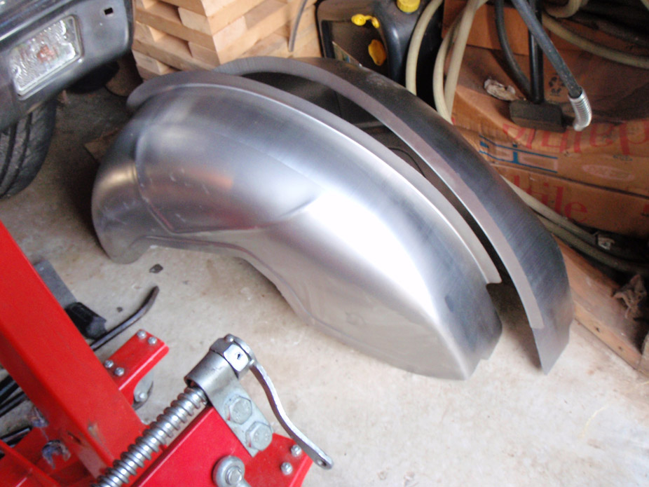
I didn't feel like cutting, so instead moved onto the front suspension. Before I start jigging together some new tie-rod/steering-arm bumpsteer setup, I need to measure what my bump steer is currently.
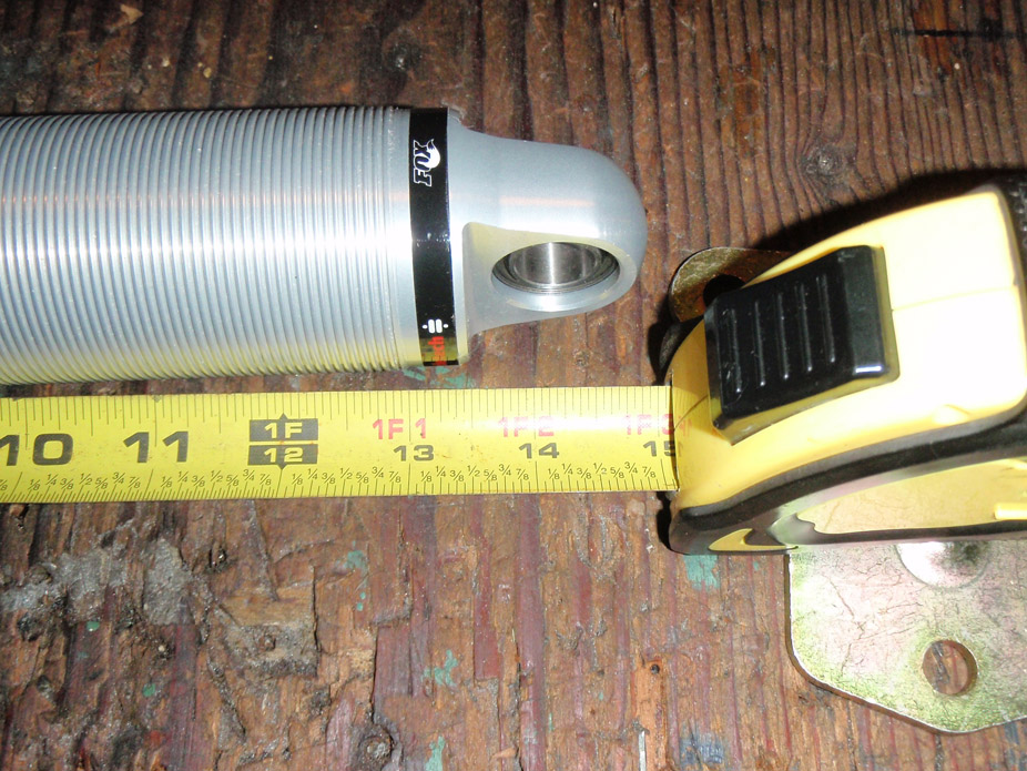
Before I can do that, I need to mockup the new Ridetech coilovers to figure where my max bump (bottom out) and ride height are, as they have 1.25" less stroke than the QA1's they replacing, however have a longer overall body (new 3.625" shock travel vs. QA's 4.875" shock travel, also FYI the leverage ratio of a stock arm is ~ 16:9 or 1.78" of wheel travel to 1" of shock travel).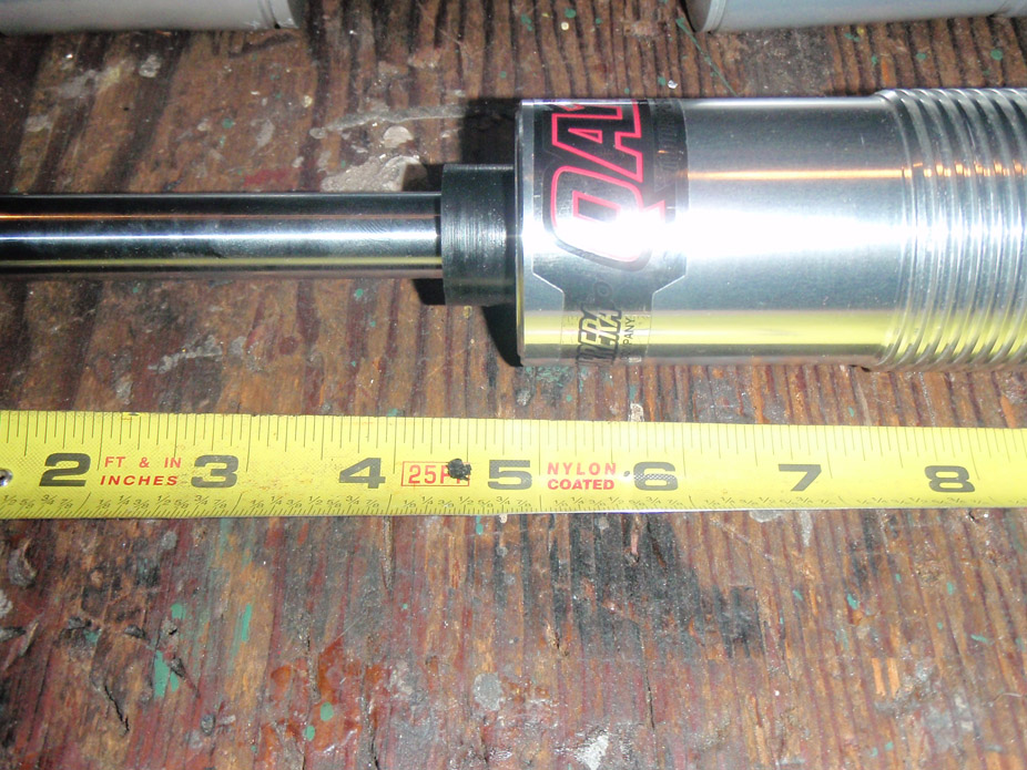
Lower bearing eyelet as measured from where stud bushing would be contacting the shock support on the subframe..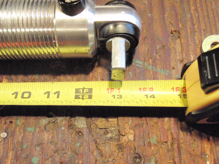
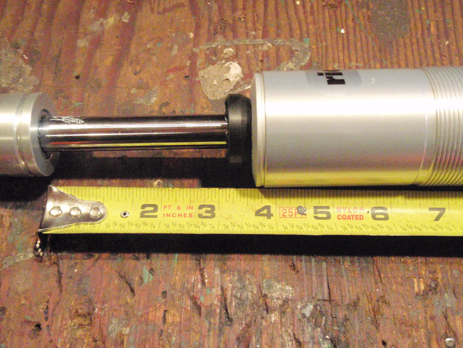
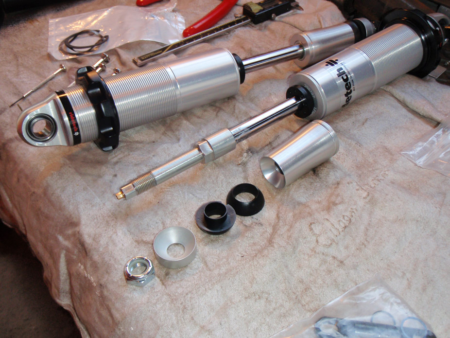
The QA1's had a standard rubber bushing/stud arrangement like a stock shock or sway bar end, but the Ridetechs have this neat spherical plastic 2-piece setup..
Mocked in there..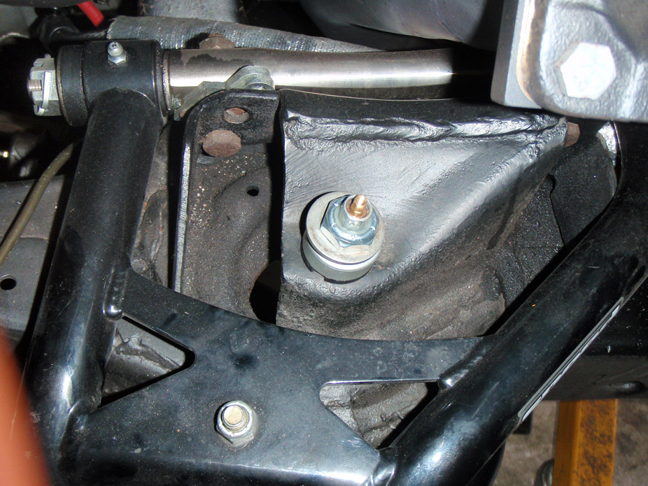
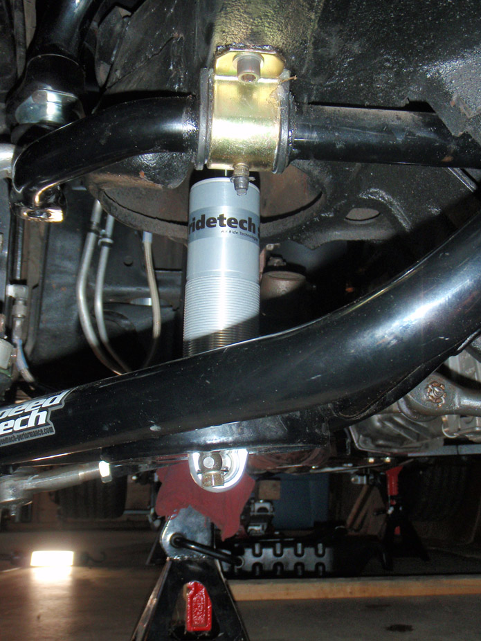
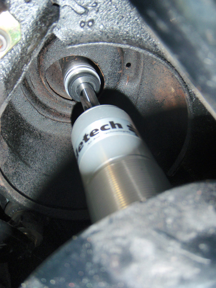
At full compression, the control arm has about another 0.75" at the shock that it could compress before the LCA's bump stop is even contacted, as well as the rim lip is just barely tucked at current full compression.
The tall upper aluminum spacer (as seen in the disassembly pic) can be purchased in a lower height to reduce the stud-bushing-to-lower-bearing length, without reducing stroke, however since the supper coil perch would be raised relative to the shock mounting point on the subframe, I'd have to cut out the stock spring perch on the subframe to gain clearance for the Ridetech's coil to partially pass thru the subframe, and I think too much cutting would need to happen and it would compromise the upper perch's strength. Plus I just don't want to have to cut a lot on the frame, too awkward and messy.
What I plan to do is switch the trunion-style lower shock mount over to a double shear bolt setup, so I'll grind out some clearance on the LCA to allow the coil body to pass thru, and then weld on two L-tabs on the bottom side of the LCA's spring pocket, at a lower height to lower the front a bit.
1-8-2013
Not a car update but thought I'd share a side project I've been tinkering with over the holidays. I like drinking beer. And shifting gears. Why not combine the two (legally)? Besides, prettymuch none of my friends know what the inside of a trans looks like.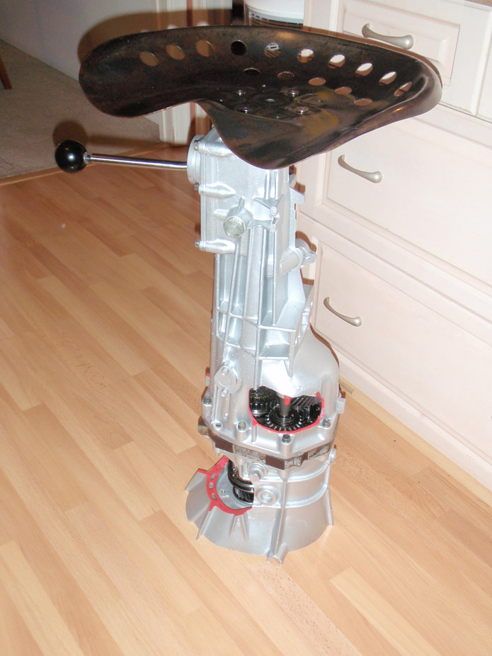
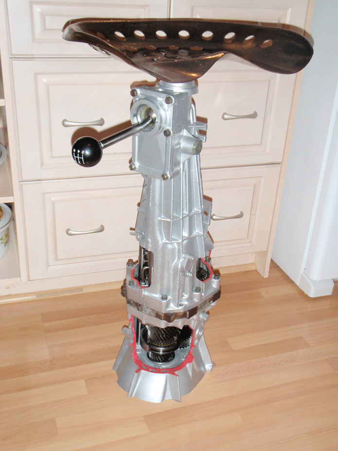
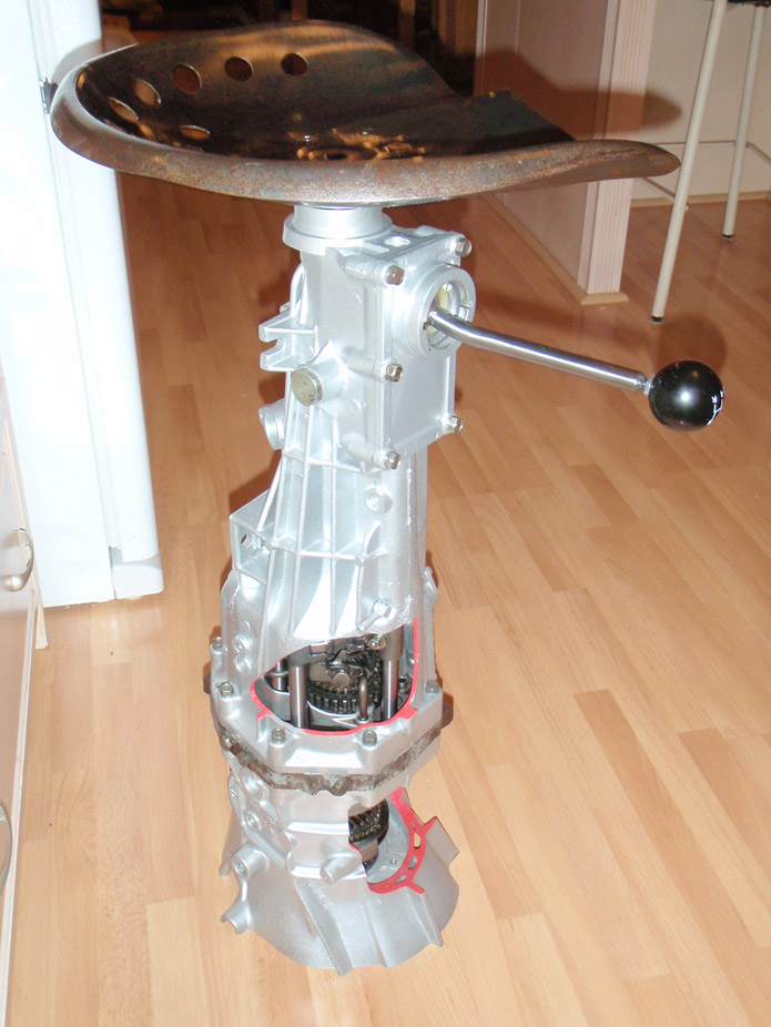
1-9-2013
Also, was cleaning out the pictures on my phone and found this.. you guys have these down in the states??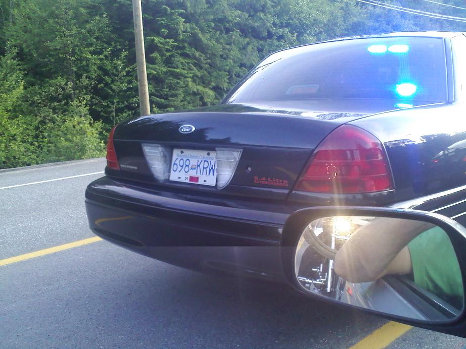
Too much time on my hands.. haha. Guess that's why I got this?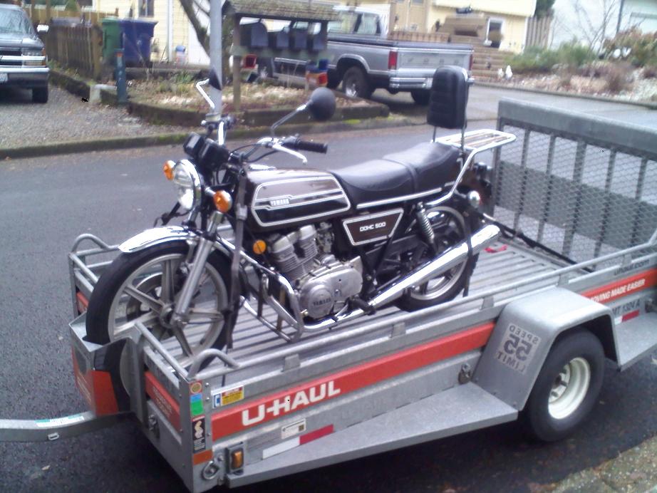
I had no idea that they even crammed that S/C 5.4L into those Crown Vics.. even for a heavy fullframe car that thing must go well on the highway..
I'm not going to go full cafe racer on it, not sure I like that hipster style. I'm going to go for more of an upright scrambler/brat/bobber style. I have still yet to find a single build of any-make twin that captures what I have in my head, but elements of these are along the lines of what I'm going for...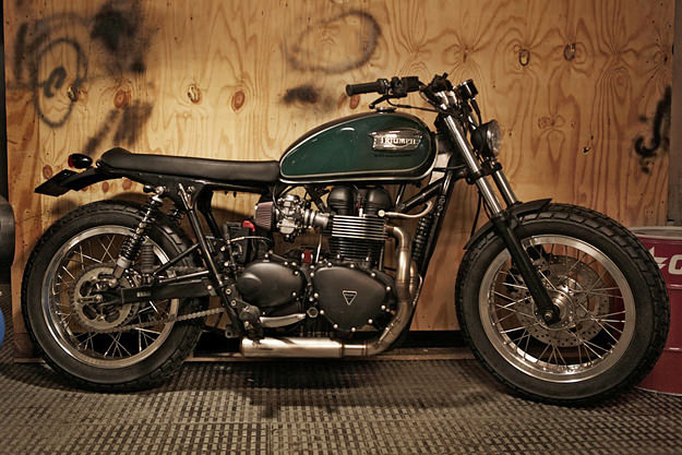
1-18-2013
2-1-2013
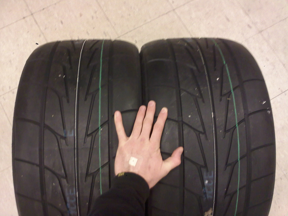
Rims widened and tires mounted.. this put a gigantic ****-eating grin on my face when I first saw..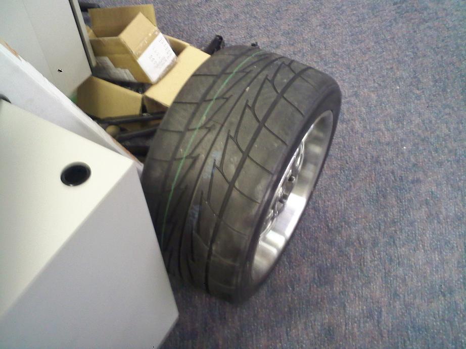
Sidewall is perfect with a slight bit of stretch. Will also look good if I decide to go to 315's at some point..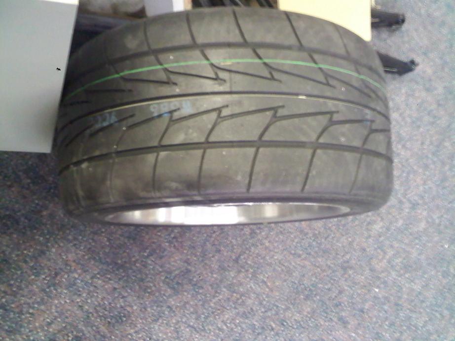
Haha I have no idea where the expression came from. What I was going for is.. every time I look at the tire it makes me giggly because it's just so ridiculous..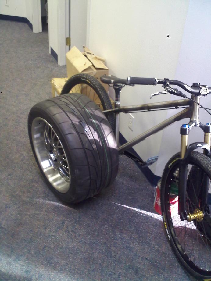
2-16-2013
Not much new to report here, garage concrete floor and tools have been cold and that puts a damper on the excitement of going out there. But I did get a new addition to the garage.. cleaning out the shop at work one of the guys gave me his old stereo setup..
Went from this..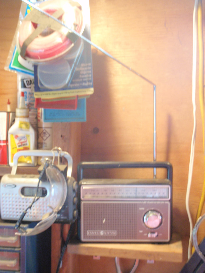
To this..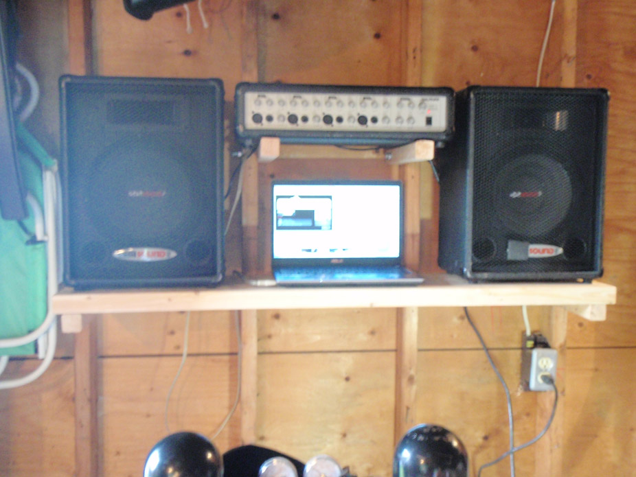
Amazing how it only takes a little change/inspiration to get back at making stuff..
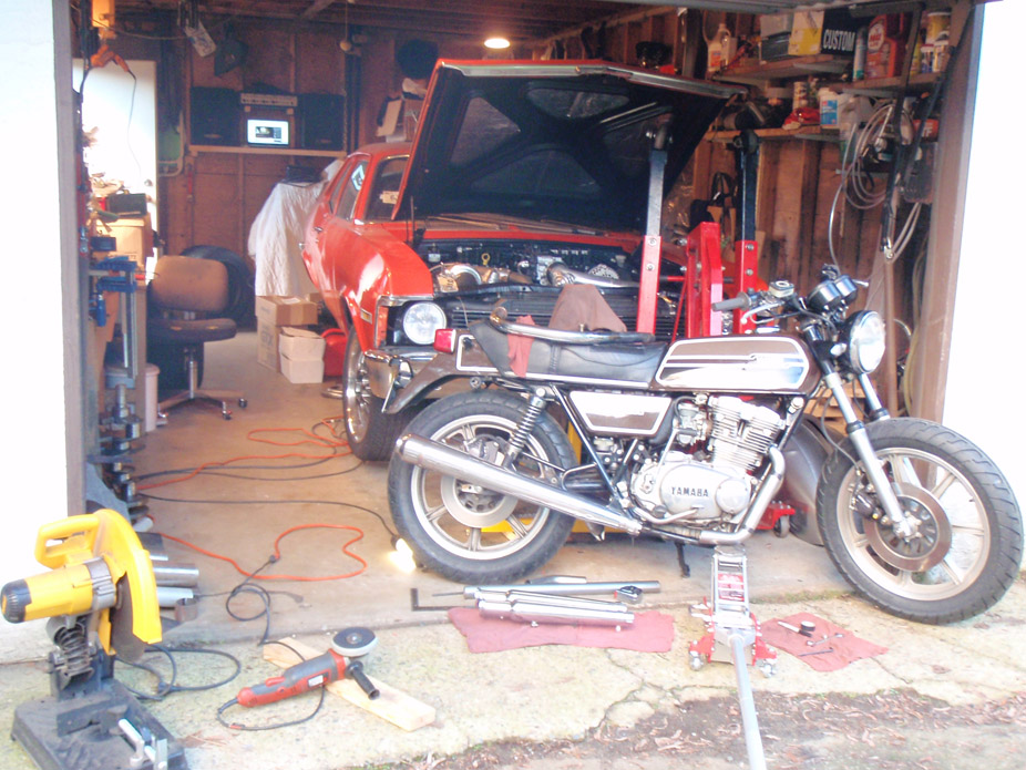
Have left hibernation and back to having the fabrication bug.. recently when I've been trying to fall asleep all I can think about are rowing thru the gears and hearing the turbo spool, so I think next weekend I'll buckle down and get thru the mini-tub.
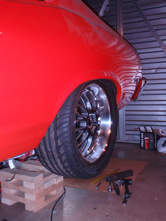
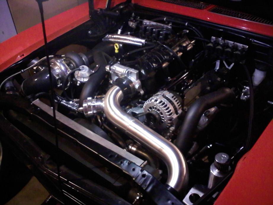
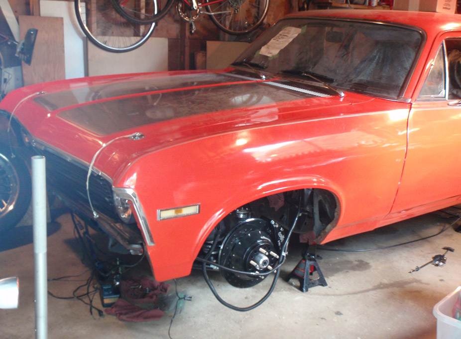
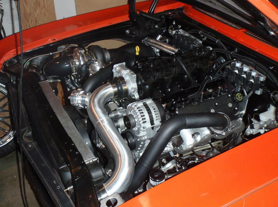
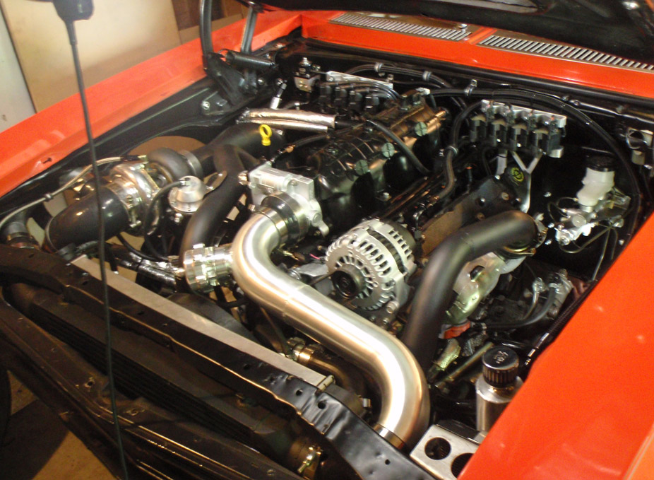

Wow thanks for sharing!
Posted by Diggymart on 3/3/19 @ 12:40:25 AM