You must be logged in to rate content!
6 minute(s) of a 891 minute read
7-30-2018
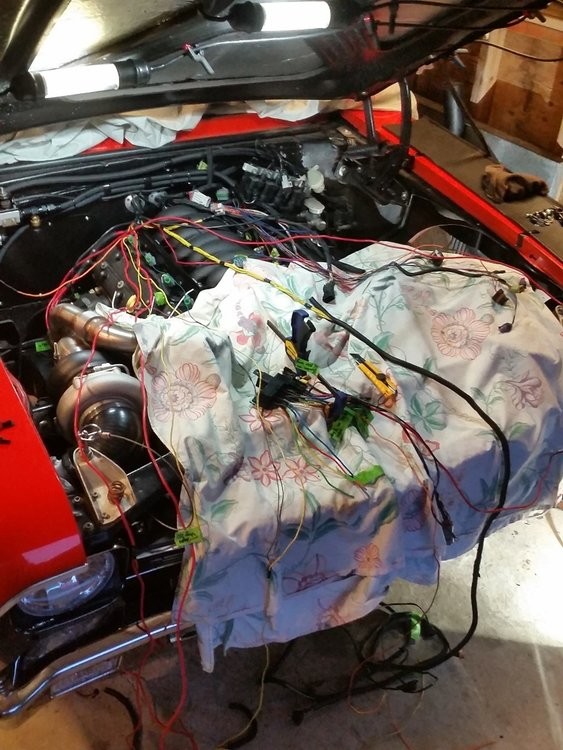
This weekend I got a fair amount done although it was varied across a bunch of different areas. A lot of my previous wiring was poorly crimped and/or just soldered and wrapped with electrical tape (my handiwork circa.... 2010-2011) so I wanted to inspect everything and anything that looked remotely suspect I re-terminal'd and crimped using my cheapo hydraulic hand crimper (for 4-8ga wiring) or my ratcheting crimper (10-16ga), with heat shrink over the terminals and new corrugated loom over top of that. I didn't take many pictures because most of it was late Saturday night, but the end result is pretty tidy so maybe next day time in the garage I'll snap a few pics. The work I completed Sat night and Sunday was:
- de-loomed the headlight/signals/horn/fans wiring and inspected/cleaned up while moving the wiring from under the driver's fender to under the passenger fender
- ran 4ga power wire from the firewall main power bulkhead terminal to the starter (crimped, heatshrink'd, loomed, then DEI heatshielded)
- ran 4ga power wire from alternator to starter (crimped, heatshrink'd, and loomed)
- ran 10ga power wire from the starter to rad support relays (crimped, heatshrink'd, loomed, then DEI heatshielded)
- started running wires from the added sensors to the firewall, to then pass thru and pin to Holley ECU
I also:
- welded in my custom rad support structure, primed it and painted
- got several potential rad hoses, started cutting and mocking up required aluminum bends to route upper/lower rad hoses
- installed front bumper brackets for good
- removed driver side downpipe to heat wrap around steering box, then re-install for good
- measured hood gaps and re-aligned, then adjusted hood locations
- filed bellhousing at starter nub to have a bit more clearance to passenger side downpipe v-band clamp
- cut passenger side fender inner lip to allow tire clearance at full bump (copied the trial cutting work I did on driver side fender months ago)
- removed gas tank to add a better vent system, as well as allow room and better safety for cutting rear bumper and bumper support structure for exhaust tips
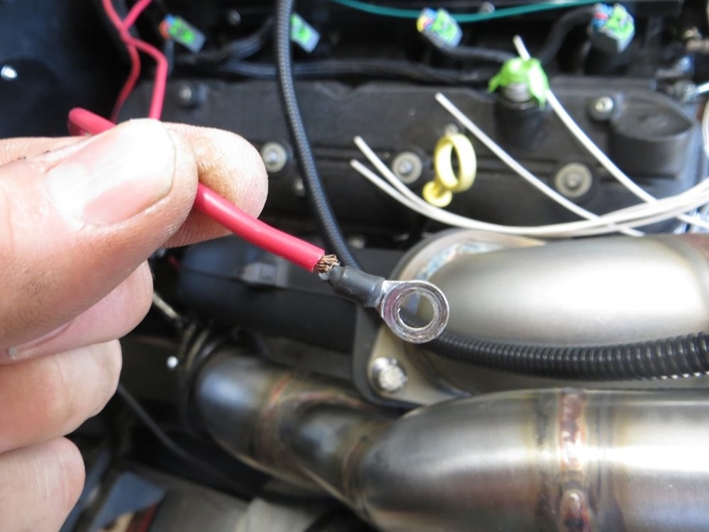
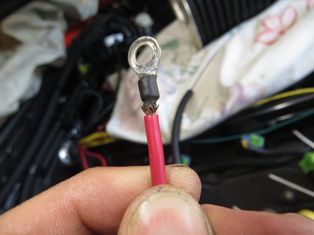
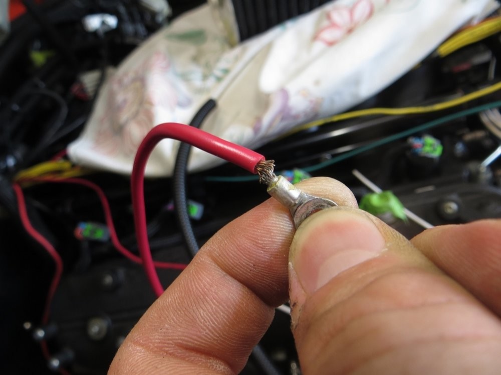
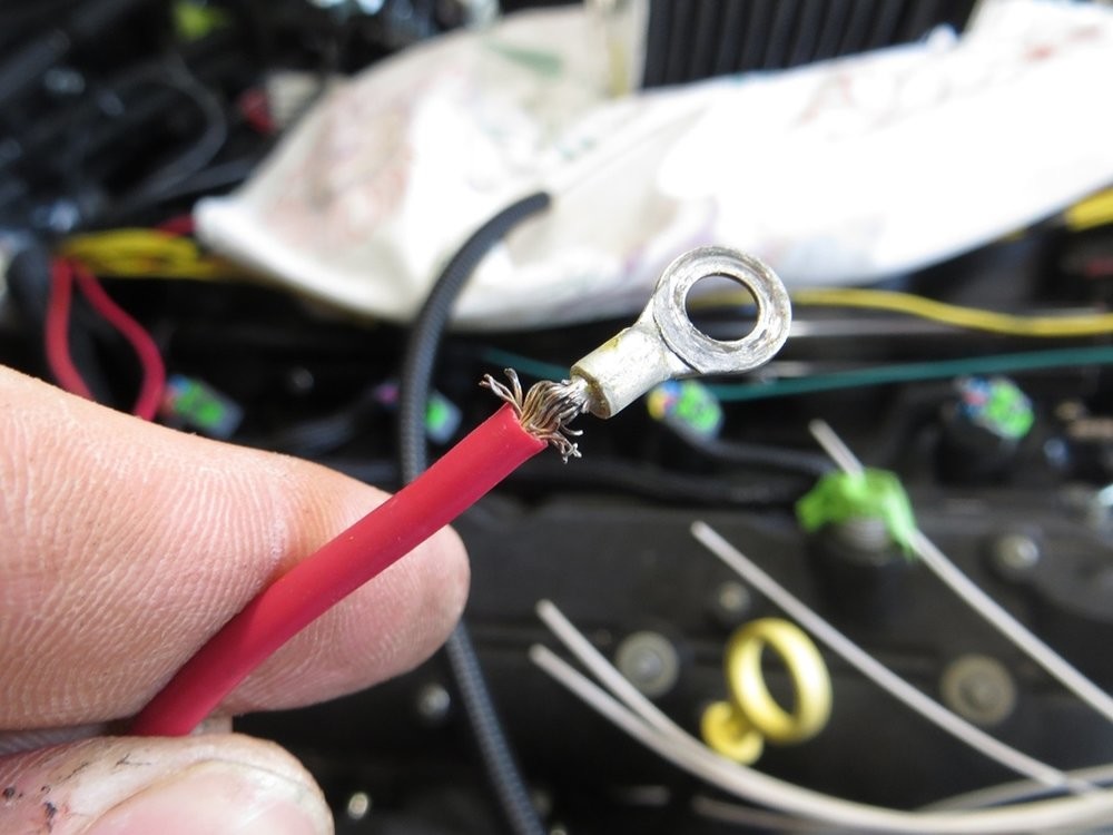
Here's a good example why it's best to not solder a terminal or connection.. this was the starter solenoid that was just soldered and not crimped. This wire was ziptied to the starter to keep it out of the way.. and years of engine vibration was enough to make the copper strands start to break right at that harsh line of rigidity where the solder ended...
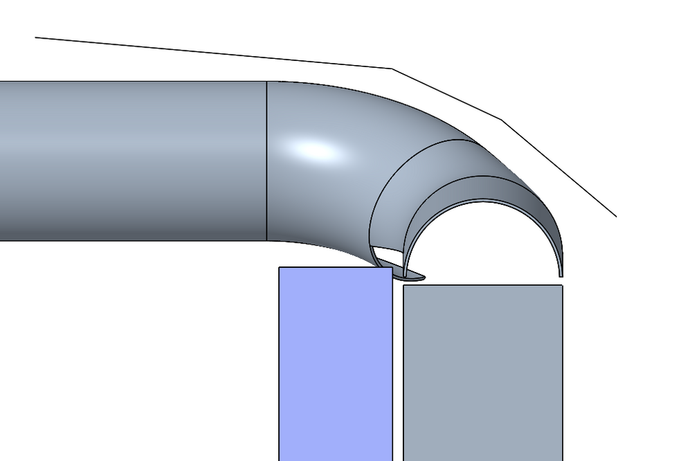
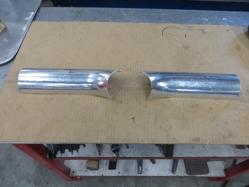
The other thing I wanted to hammer out is what a nice intercooler top tank would look like. Thought 3.5" tubing looks nice and smooth, so I wondered how I could use 3.5" bends, and this is what I came up with.
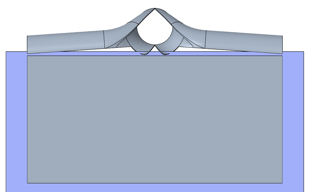
The mandrel bends on the core side are 45 degree bends that are rotated 36 degrees up from horizontal, and then the bends used for the merge are 60 degrees that are just oriented so that they're perpendicular to the core...
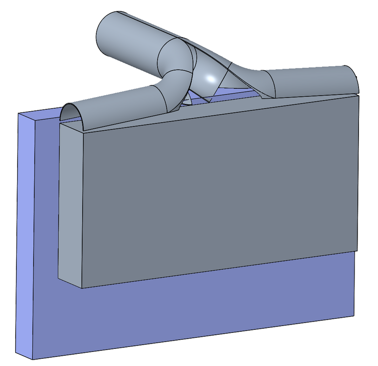
5 degree angle of the "shoulders"...
This is the necessary S-bend that I'll need to clear the rad but swoop back down to the throttlebody double-hump coupler. The red line also shows the bend I'll need to add to the filler plate to have the elbow clear the top-front edge of the radiator, but also smooth out the flow direction of the air leaving the top of the core...
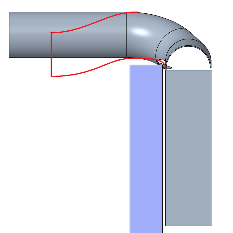
Naturally I took a handful of 2D dimensions to measure and recreate the underside of the hood structure, which is shown... currently has 1/2" clearance.. if it ends up rubbing then the hammer will come out haha....
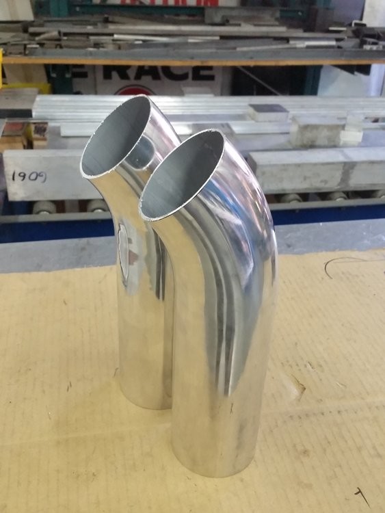
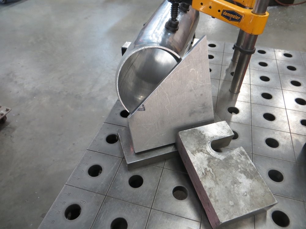
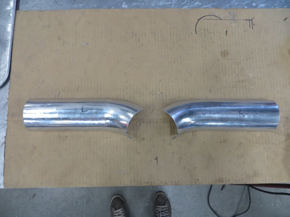
I started with the only bend I had left, a 90... which I cut into two 45's...
I then clamped it horizontally...
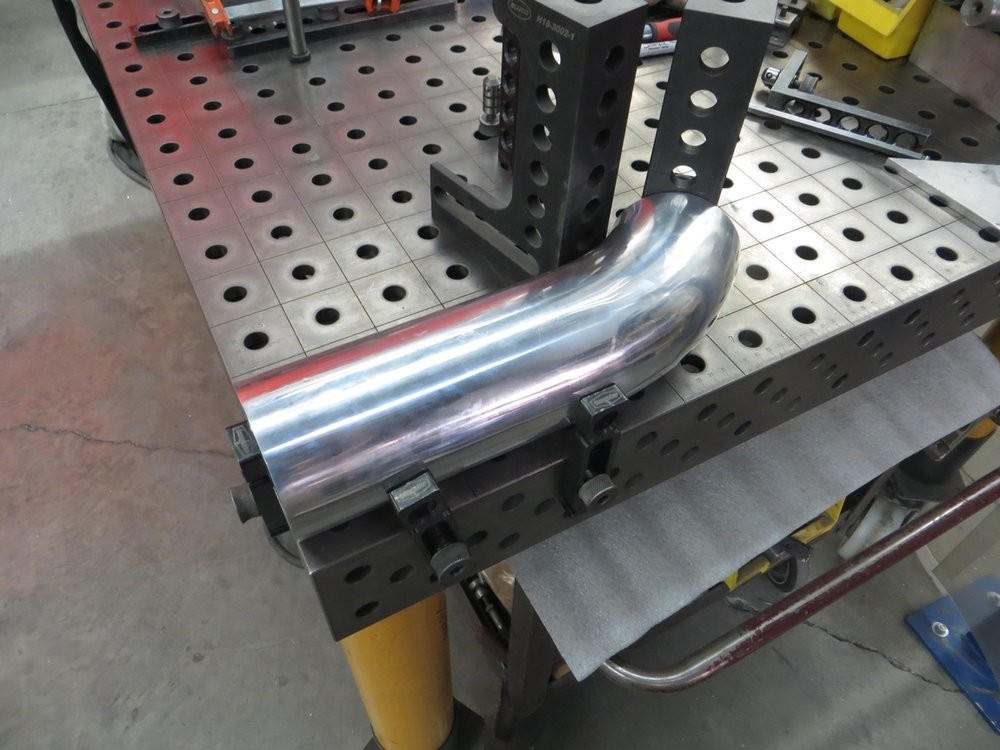
Which allowed me to scribe (with a steel block) and then marker the centerline of the bend plane
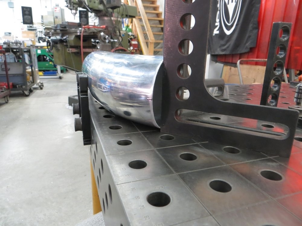
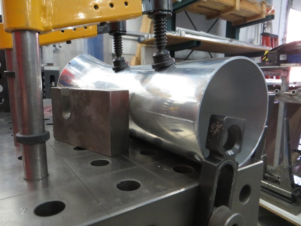
I then quickly milled a plate with the 36* angle on it, as a rotation guide, and clamped the tube once it was oriented in that 36* orientation...
Then used the steel block again to scribe the new centerline for the tube once rotated to that required angle. This scribe line will become the cut line...
Always easiest to go over that scribe line with a marker to make it extra clear once you start cutting... only want to cut once, the right way!...
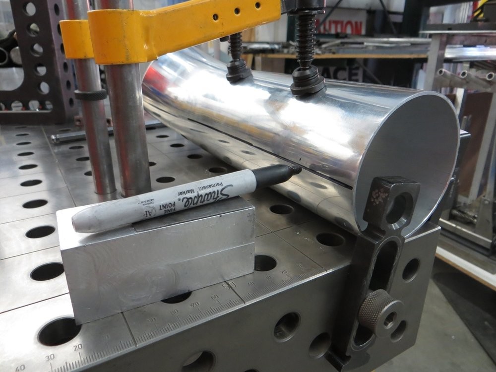
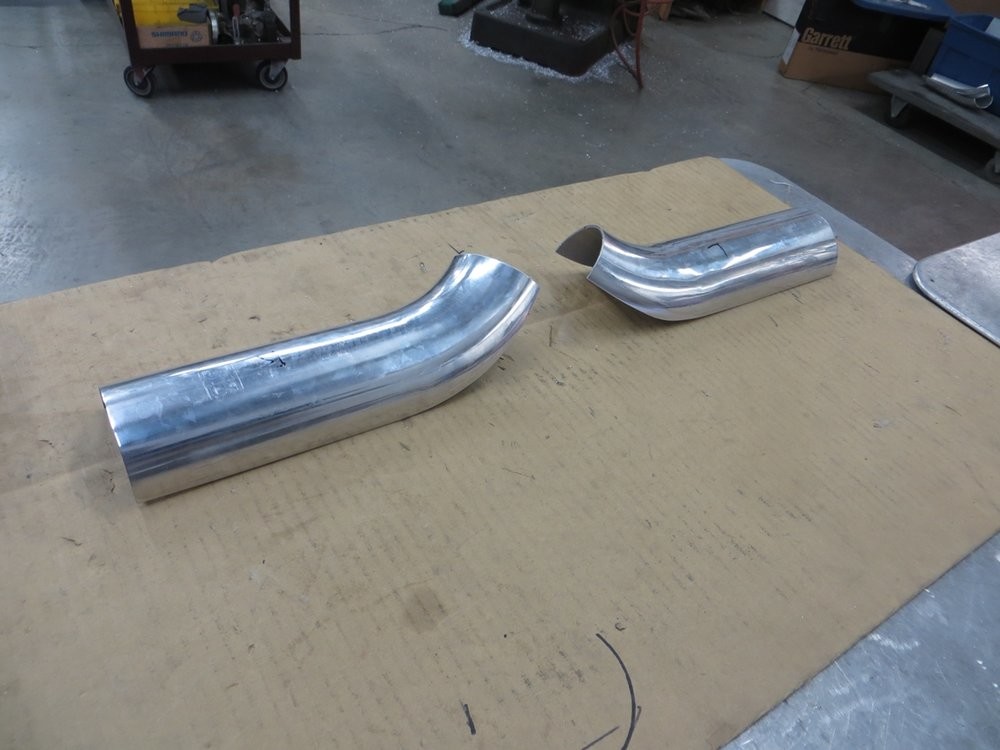
I finished the cut line off around the bend by just eyeballing what my best guess would be for the contoured filler plate wrapping around the assembly...
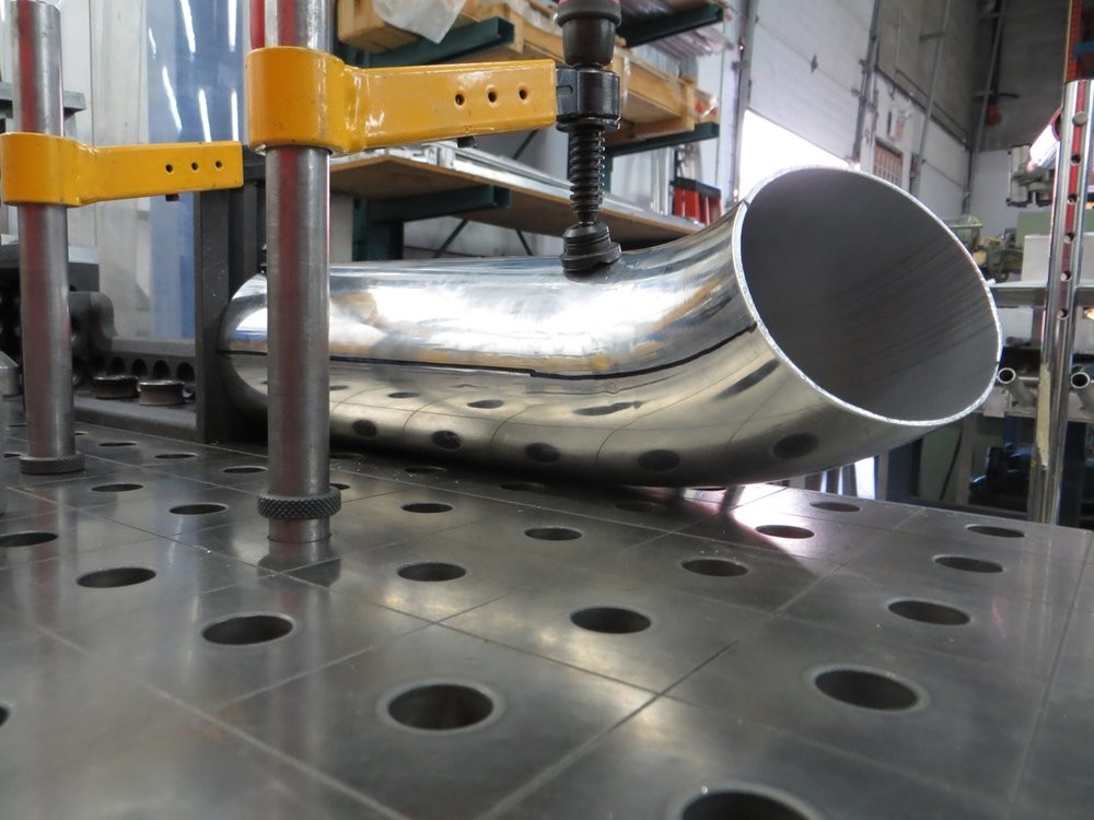
And here we have the bisected tubes that will hopefully soon start taking shape on the top of the intercooler core....

Wow thanks for sharing!
Posted by Diggymart on 3/3/19 @ 12:40:25 AM