You must be logged in to rate content!
10 minute(s) of a 620 minute read
1-24-2012
BomberJeep, thanks, I was just thinking today how lucky this 62 year old truck is to be the test vehicle for my ideas of fabrication.
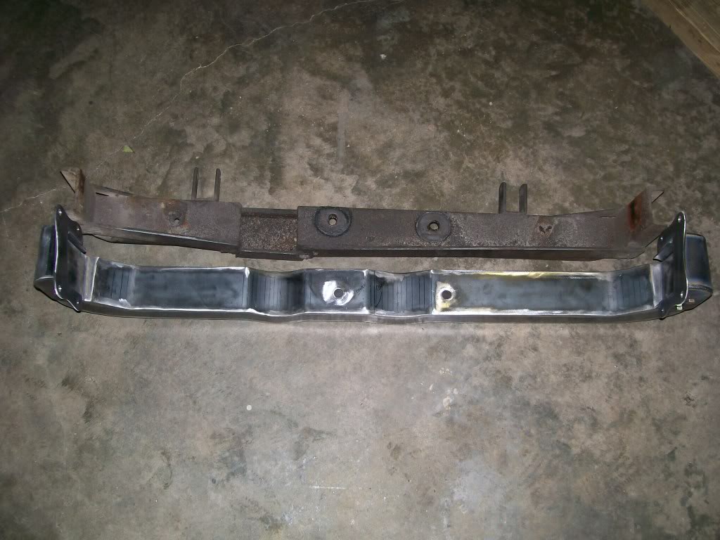
Back to a comparison picture. I knew the old one was rather primitive, but it worked. I don't know if the new one is way advanced, or the old one is extremely un-advanced,
 but I really like how the new one is coming together. This has been another project that I had to really step up my abilities, I was a little hesitant at first, but I'm glad I took on the challenge.
I did drive the truck to town today. I have to laugh, never in my life was a crossmember a subject of conversation. One question I got..."is that a soild hunk of metal"? Once again, mission accomplished.
Ok, lets compare in a picture.
And one with the mountings in the focus.
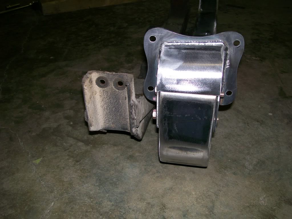
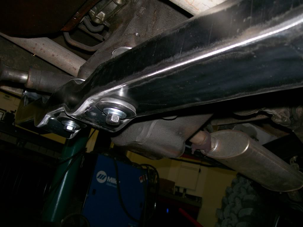
Something I haven't shown yet is the bolts and bushings holding the transfer case to the crossmember. For these bolt holes I also had to drill and install anti-compression tubes. These tubes serve another purpose. All the weight will be supported on the top of the crossmember, the tubes are welded to the top plate and to the bottom plate. These tubes will transfer the weight to the bottom plate as well and keep everything equal.
1-25-2012
A couple pages back,(I tried to go back and find the page, but my dial-up was taking way too long) I showed using the drill press to make oversized washers. I ended up calling them....RPBA, or something like that.(if I could go back to the page I'd know for sure, dial-up.
 )
)
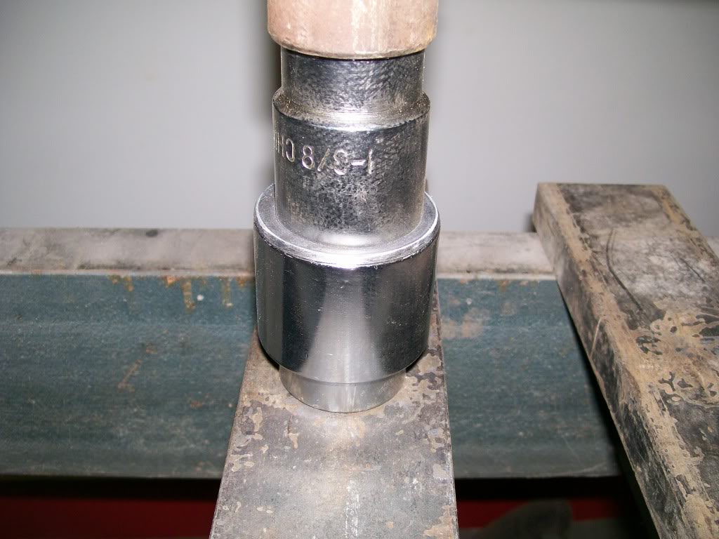
Anyway, the idea was to apply pressure, or weight evenly to a rubber bushing. One step I didn't show was forming the metal washer into a cup that will help encapsure the rubber bushing. Since I'm using these to mount the transfercase to the crossmember, I took some pictures.
This time I didn't use the drill press. I had the torchmate ready to go so I made the round discs with the torchmate. The drill press works fine, but I could cut out 4 discs in a minute or two with the torchmate.
The disc on the on the left is the end result on a bushing, the next to the right is the finished disc before drilling, next is disc after grinding off plasma slag, and the far right is just after the cut.
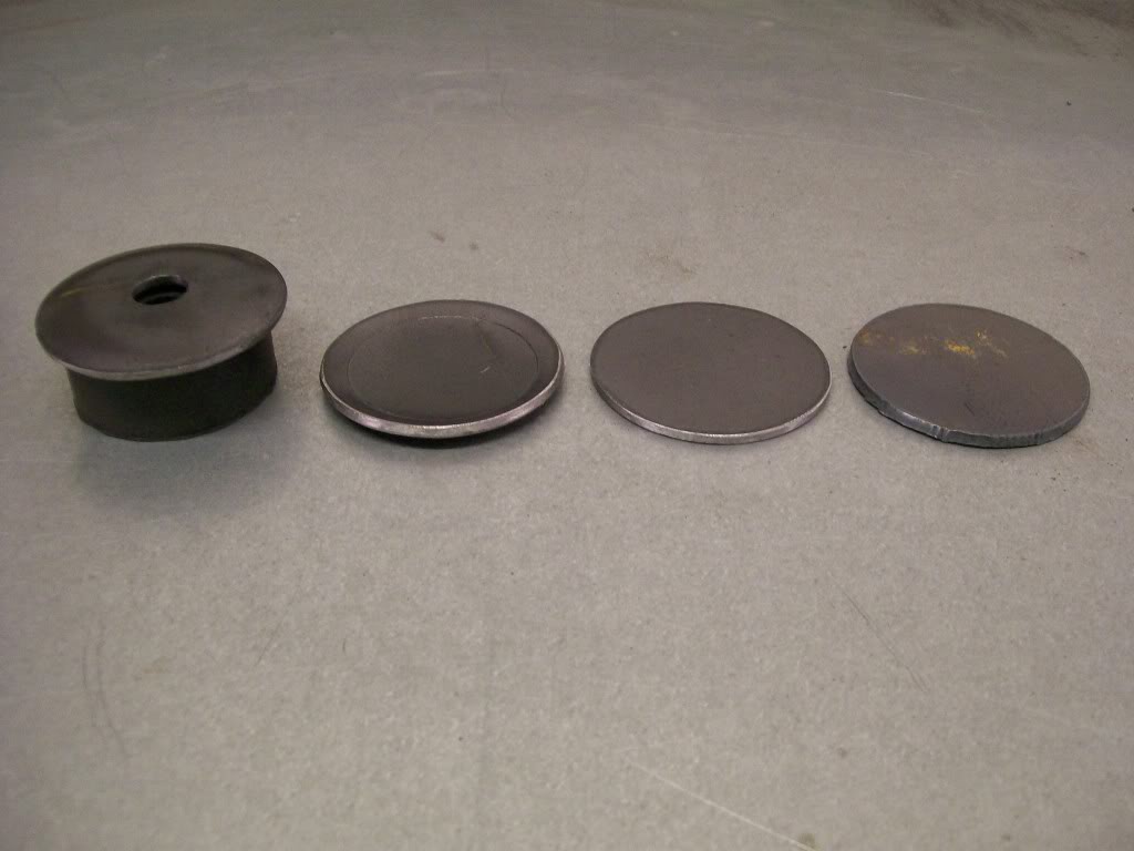
How to cup the disc.... one large socket with a smaller one pressed into it with a metal disc in between. To center the hole that I will drill through these discs I will put them into the lathe, spin them and bring a drill in and drill the perfect center.
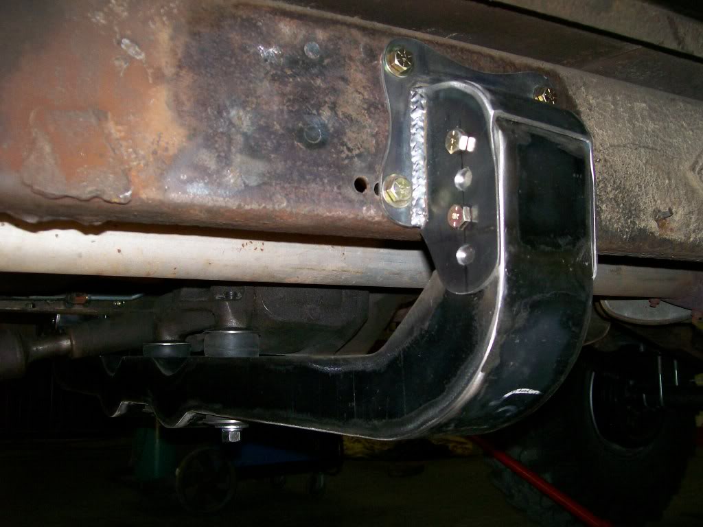
Back to the crossmember progress.... There is a term I stick to when building most anything, I believe it's called "material safe". Anytime I can I will cut with extra material left to work with. That's where I am with the crossmember hanger. Looking back at the last set of pictures you'll notice the two bolt holes where the crossmember fits the hanger, the bottom hole is close to the bottom of the hanger side plate.
With a whole different set up of crossmemberage, I didn't have an exact measurement for the fit of the new one. So I built in extra material in the hanger sideplates.
Now that all the pieces are cut and built I can now get exact sizes. In this picture you can see the mock-up holes, and now the final assembly holes. The extra holes are no problem, they will be welded shut and ground smooth and the extra material hanging down will be removed and cleaned up also. I gotta tell ya....I really like these hangers.
1-26-2012
Ok, that's 3 for nice work. Thank you all.
Finally I'm about to bring this crossmember to a close. Funny, it's been the items that are usually overlooked that have been the most adventurous to make. Let's see, we had the upper spring plates and the clover plates, we had the rear shock mounting brackets, then the rear bumper mounts, and now a crossmember. Things we take for granted, yet, I can complicate the heck out of them all. Oh well, it's certainly given us all chance to step out of the box and do a little fabricating and that's what it's all about.
While I'm at it. One other bit of advise I can give that doesn't pertain to fabrication, so much as "showing" fabrication. I wander through some of the other build projects and I need to give advise. As you all can tell, I can write all I want but it's not til the picture is presented that the words really can be applied. I send all my pics through photobucket, then attach them here. It seems photobucket resizes them to the perfect size for this forum.
The pictures I post on here are not the only pictures I take though. I figure I've posted close to 300 by now, but I've actually have taken over 500. The only cost is a couple more batteries, the digital pics otherwise are free.
Why am I writing this????? Many of the pics I take are slightly out of focus, the flash reflected and was too bright, the picture is too dark, I found a better angle that told a story instead of just an image. ect.... If anyone is working a thread, or starting one, don't just take one pic and be done, take a couple and at different angles, you'll have a better set of choices to post later.
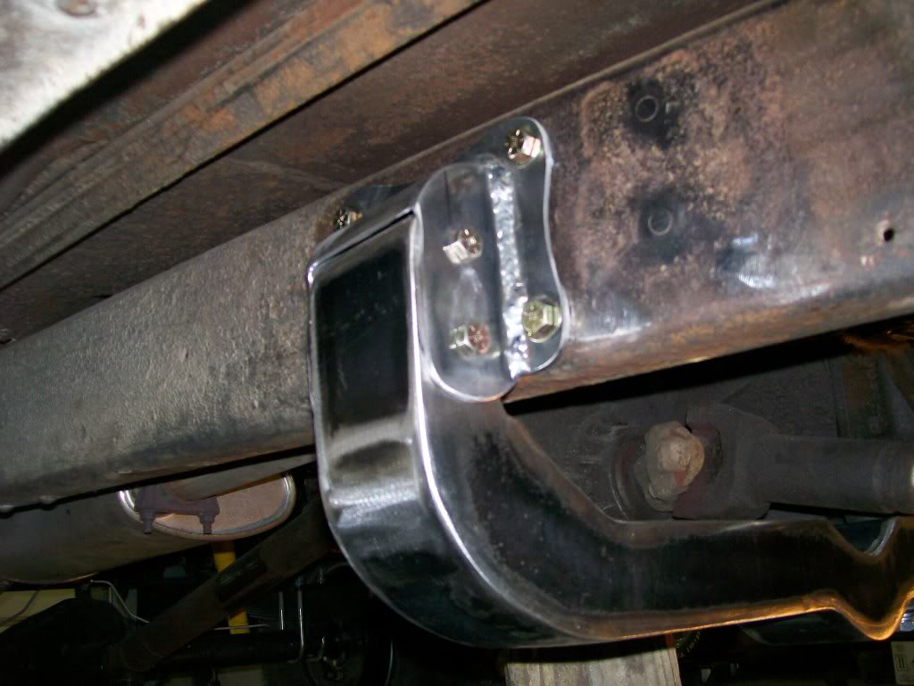
I mentioned the idea of being "material safe", in this picture I'm done with being material safe, I know exactly how I want the final fit. You can see I've welded shut the extra holes in the side plates, and ground them smooth. I also cut off the excess hanging side plate material and rounded off the bottoms. Everything has now come together.
Happy with the creation, everything went outside for sandblasting. The crossmember, the hangers, the bushing washer thingys, and the long bolts. Why the bolts?? I had to make one, so instead of it rusting, I'll blast and paint them also. Talk about taking multiple pictures, I took 4 pics of just these sitting outside like this. The winter sun is at such an angle, the shadow on the crossmember gave a different image. So take many pictures and delete the ones that you don't need.
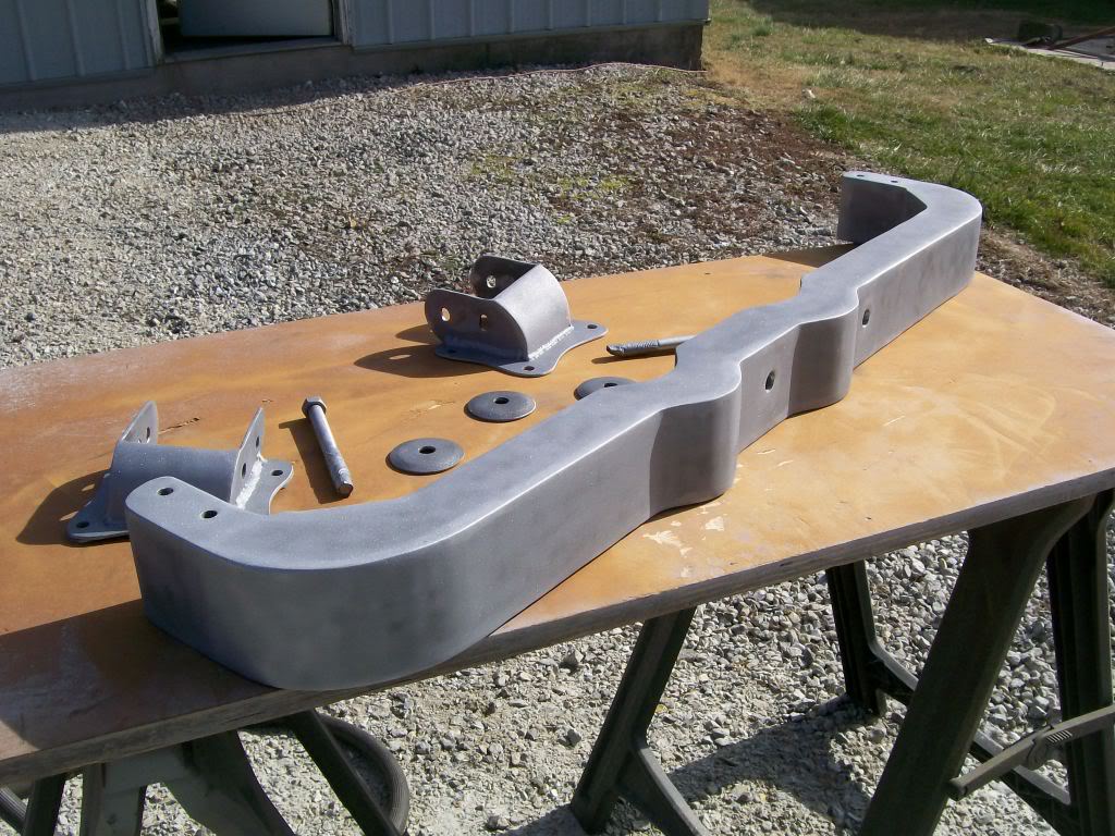
Here we are. I used the bedliner black spray. Within 2 to 3 hours these were dry enough to assemble. I took two pictures of these. The first picture had the shop door in the background and altered the image I wanted. This second picture is the one I posted, then deleted the other one.
Occasionally when building or fabricating, you'll need a bolt of the size you just don't have around. Over the years of metal working there are 2 items that are needed sooner or later. 1) Threaded rod. 2) Round bar, non-threaded rod.
In no way am I endorsing the use of a "home made bolt", but I am endorsing the idea of building one to use when all else fails. Shall I say "Mcguyver". (spelling?)
In my situation I needed a 1/2" bolt, 5 1/2" long. I had a 5" but it was too short.
I'll leave this bolt in place, but only because it really has no torque applied to it. The only pull against it is mainly the resistance of rubber bushings.
There, now that I've put to rest the people who want to declare how unsafe this bolt is, I'll continue.

In the case of this bolt I used a 1/2" die and threaded a piece of solid round bar about 1 1/2" long of threads.
With the bar being about 6" long I threaded the other end about 1/2" down. Then run a nut down these short threads til it stopped. Then tig weld the top of the nut to the short stub of rod sticking out past the nut. The other side of the nut can be welded to the rod also, but you pretty well have to use a tig welder here. You can use a mig welder on the top side, but the mig will build up too much weld on the bottom side and when you tighten the bolt, the excess weld will get in the way.
Once again, it's not like a grade 5 bolt which is the least required hardness in most applications. But this is an option when you're in a bad spot.

Ultimate classic truck right there
Posted by CCmyVW on 12/26/20 @ 4:17:42 PM