You must be logged in to rate content!
15 minute(s) of a 620 minute read
11-26-2011
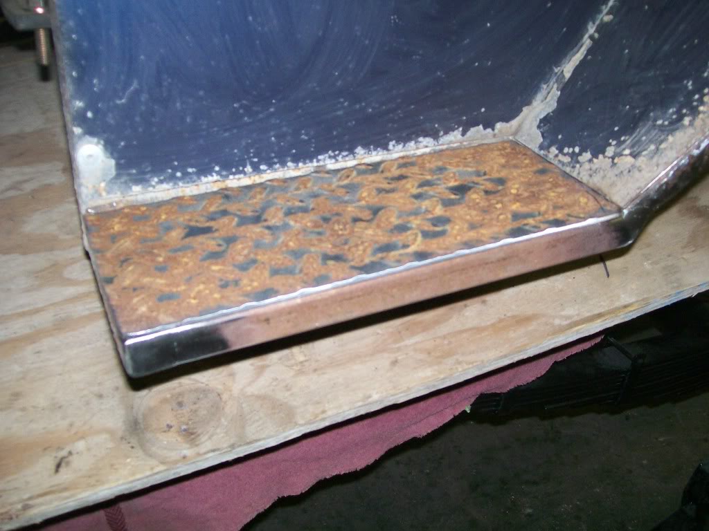
A little more on the old bed work. On the old platform I had some plates painted the light blue color. Now that I have some left over diamond plate material from the rear step, I'll cut and install some here also.
With the new tube welded in, here's how the plate will look when in place.
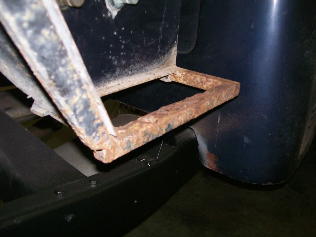
Now the passenger side. That looks terrible. Where the down tube meets the step tubing you can see a opening in the end towards the wheel. Here's where the problem starts. The wheel was able to fling everything right into this opening and most of the rust began from the inside. It's a stange rusting effect. You can tell that the moisture trapped inside the tube expanded from freezing and distorted the square tubing. Oh well, lesson learned.
11-27-2011
"a flood" , surely we can't allow that, good thing I got tall tires on the Willys.
I'm still taking care of the bed decay. I can't tell you how temping it is now that I've replaced the bad sections of the bed, to just go ahead and sand the rest of it and paint it right now.
More important right now is to get the front leaf springs changed. Like I said before, the new suspension in the rear raised the back end about an inch to an inch an a half. Even before the change in the rear I thought the front needed a little lift anyway, so it is next to be updated.
Right now we'll take a look at the passenger side bed repair. It's coming along quite nicely. Simple cut and replace 1" tubing, then sand down the surface rust, and I'm spraying it all with the black bedliner. I'm really happy with the bedliner spray. It dries within an hour, and holds great.... I'm sold.
This first picture shows the new tubing welded in, I just need to sand off the surface rust, then spray it black. As I was grinding the down tube closest in the picture, I noticed it also had a internal rust problem. When I put this together years ago, I also left a small opening where water, salt, and dirt got in the tube and destroyed it from the inside out. You can see in the picture where I blended a new tube with the old.
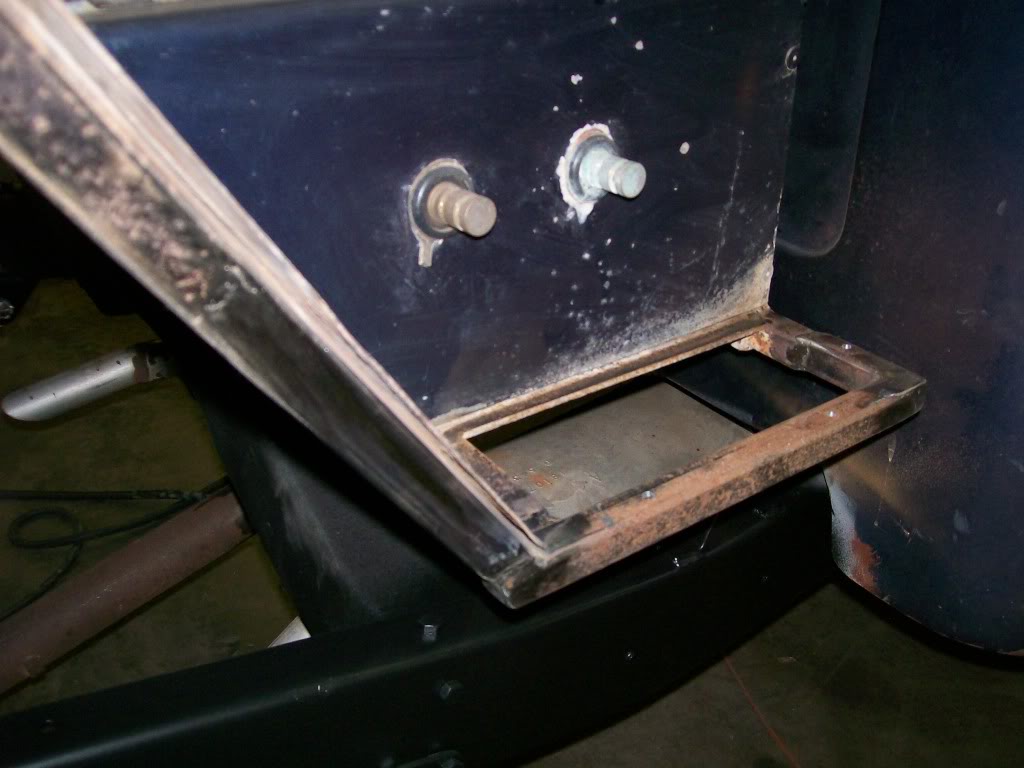
And here's an idea of how the new diamond plate looks with the bed linerspray on it.
11-28-2011
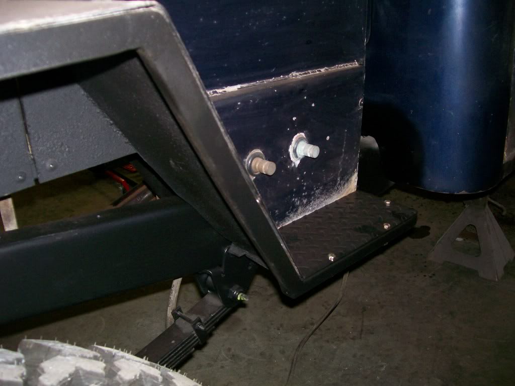
Tonight is the last picture of the bed work. I'd like to do more with it, but it's just not the right time.
I sanded and sprayed the bed liner black on the repaired areas, it looks better than it has in years.
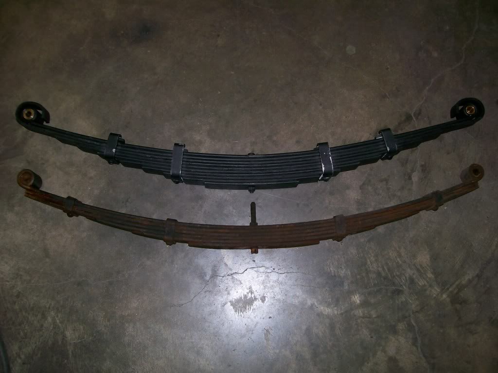
Now to the front suspension. History..... back in '85 I put the front springs in. Back then I added a leaf to make up for the extra weight of the 8 cylinder and the heavier transmission and transfer case. It was needed, even with the extra leaf it sat a little lower than I perfered.
Next update is the spring perches themselves. Somehow the ones I made back then has lasted this long, but they are weak, definetly need to be changed. As I move along I have a couple of issues I will have to overcome to do what I want to do.
A look at the old spring vs new spring.
11-29-2011
Let's look forward to the front suspension.
Through the build so far there has been talk about "spring over axle" design. This truck originally had the spring going under the axles. Now with the springs over the axle it gives a 4 to 5 inck lift without blocks or longer shackles or re arched leaf springs.
In most cases it's just a matter of reattaching the spring perches on the top side of the axles and the suspension is lifted. Just as I did with the rear axle.
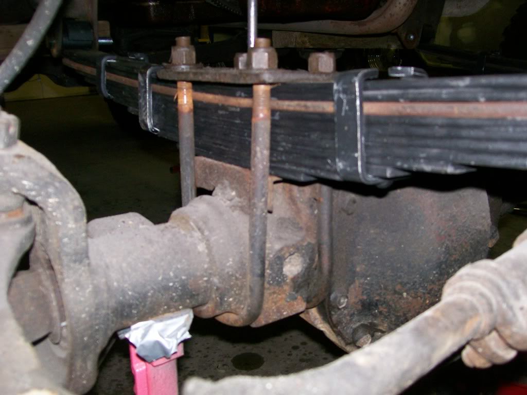
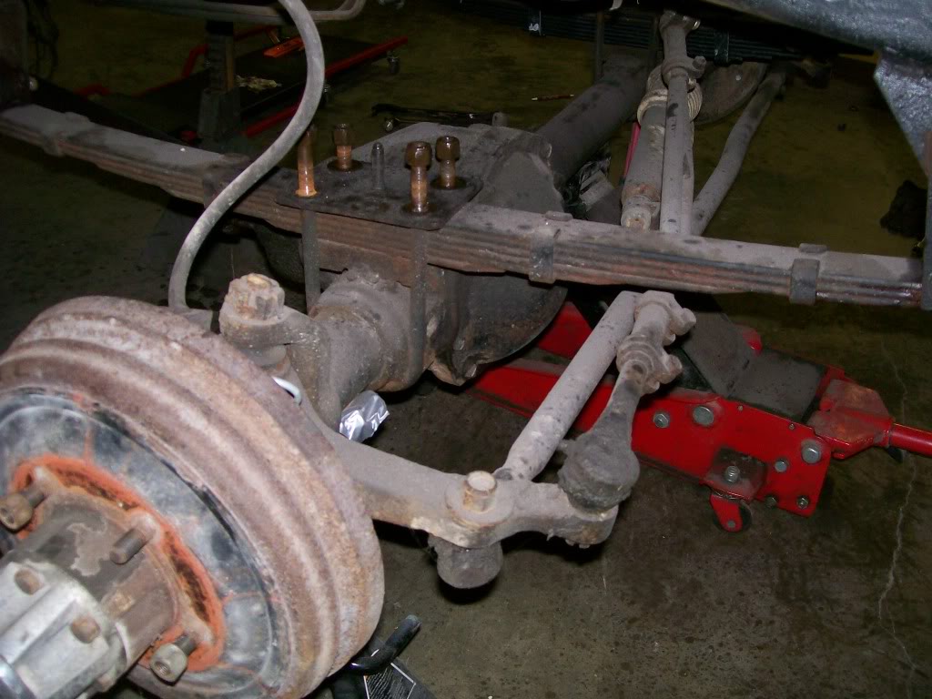
The front however has an issue. Where the carrier section is on the front axle it's off center. Plus it is designed and casted to have the leafs going under the axle. I did however get past these issues last time, but not with the professionalism I'd perfer. Lets see what we're looking at.
In the picture below, you can see the casting underneath where the leaf spring originally attached. Then you can see the adapter welded in place above where the spring is now. We'll get deeper into this later....
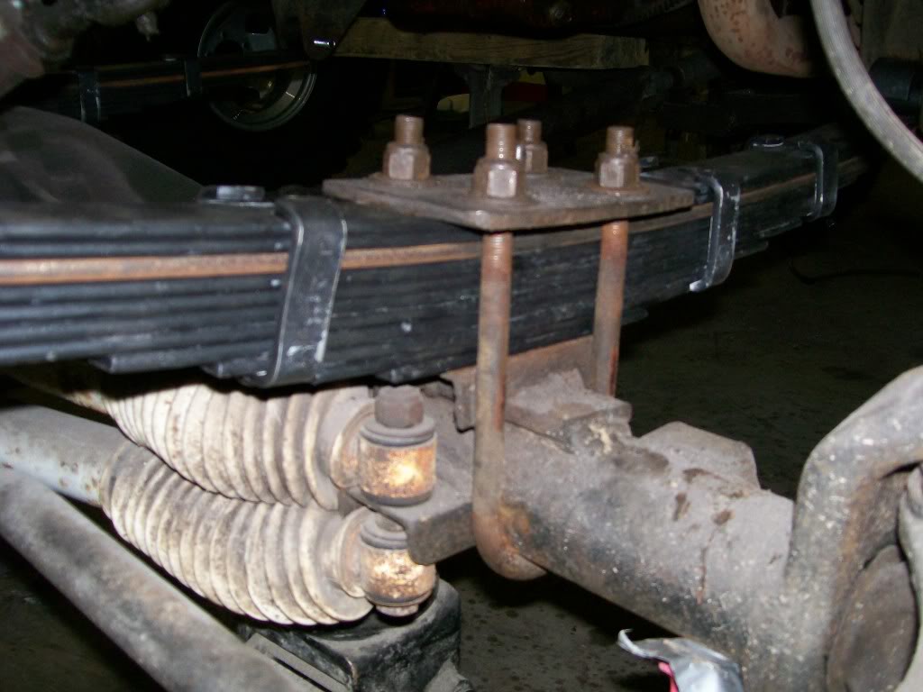
This next picture is the drivers side. Usually it wouldn't be any problem but, now that I am much more fussy, and with some measuring, I find that this perch is actually 7/16" lower than the other one. Soooo, in this re-do I have to either lower the passenger side perch, or raise the driver side perch, or try to find a happy in between where they both will match.
11-30-2011
94yjstocklook, I'm workin on keepin the distractions commin.
Pmoreau, dukie564 did a good explanation. My original rears had this same design, but the after market replacement didn't. Now the aftermarket fronts do have this design. Actually this design did do it's job, one of my old rear springs did break at the mounting bolt eyelet.
Dual stabilizers yes, and still working good. just for the sake of age I'll probably replace them.
The last 2 pics posted were during an experimental time. Look closely you'll notice a old leaf mixed in with the new ones. I've assembled and disassembled the front suspension about 4 or 5 times now. I will not be settled til I have the exact height I'm looking for. Patience.........
As I mentioned, last time I added a leaf. Now, even with more leafs in the new set, I still don't have the stance I'm looking for.
Here is a pic of the old spring drivers side.
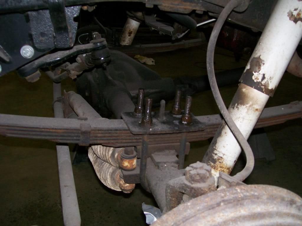
And a pic of old spring passenger side.
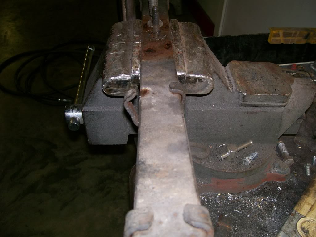
In order to get the stance I'm looking for I removed the added leaf from the old set. These assemblies have the metal clamps holding things together so a little bending is necessary. And removing the spring center bolt.
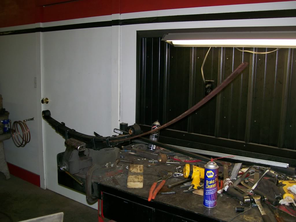
With the new spring assemblies I needed more strength and they also had the metal clamps. I started to bend them back, then I noticed the clamps had some extra space. Hmmmm, if I remove the center bolt, might I be able to slide an added leaf to the assembly... oh yeah. Took some tapping, like happy gilmore. Just tap, tap taparoo. Before this is all done I will slide the added leaf back out and paint it to match the rest of the leafs.
Finally I have the set up I'm looking for. The springs compress pretty good under weight, yet they still have a little arc to them. The old ones were almost flat with the weight on them.
Now that I have the springs set the way I want, I now have to build the perches. I can make these any height off the axle I want, but once again, the passenger side with the carrier section creating an issue, I'm gonna have to force the issue to grind it down to where I need it to be.
12-1-2011
I'm sure most of you read the comments between Jim1611 and myself about grind away at the casting on the passenger side to get more flat area exposed.
Before I did the grinding I had to find the spring rate that held the truck the way I liked. Also, I wanted to take a well thought out guess as to what the height will be when I was done grinding. This guess would be the height of a perch I would make for the drivers side. I wanted to make the drivers side and install it before grinding the passenger side. By installation I mean just a couple of tack welds. By having the drivers side close to where I want it, when I check for level while grinding the passenger side, I will get a close reading.
Next..... I've driven this for 26 years and never had a front u-joint problem. So my goal is to maintain the same pinion angle which has everything to do with the life of u-joints. By installing and tack welding the perch in place, I can mess with the axle all I want, and maintain the same angles.
Next... The are terms used in wheel alignment. We have toe-in, toe-out, caster and camber. By rotating the front axle I will be messing with the caster.
So far in this thread I've gone into detail explaining stuff. I figure toe-in and toe-out are pretty well self explanitory. If someone wants to go into caster and camber, and how they change drivability, let me know and I'll get deper into it.
I've cut with the torchmate, the three main sections to a spring perch. As I've mentioned many times before.....when possible always clamp the pieces on to a brace. This will keep the welding process from distorting the angles where the pieces meet together. This picture doesn't show it, but I also clamped the top piece on the the brace before the welding.
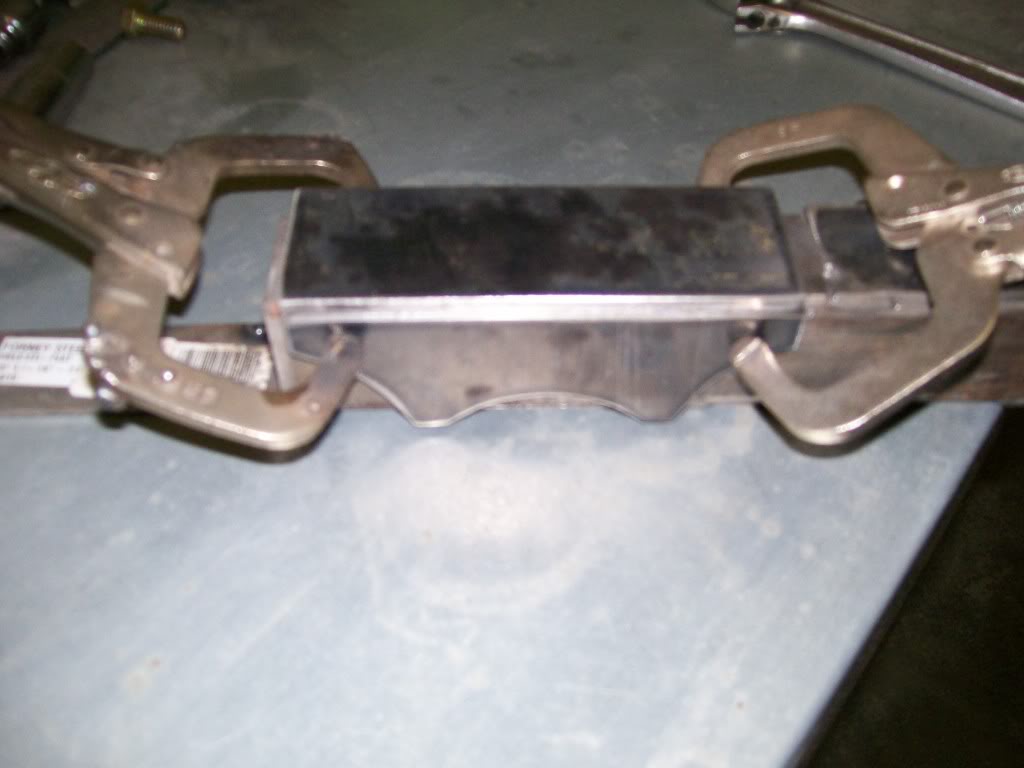
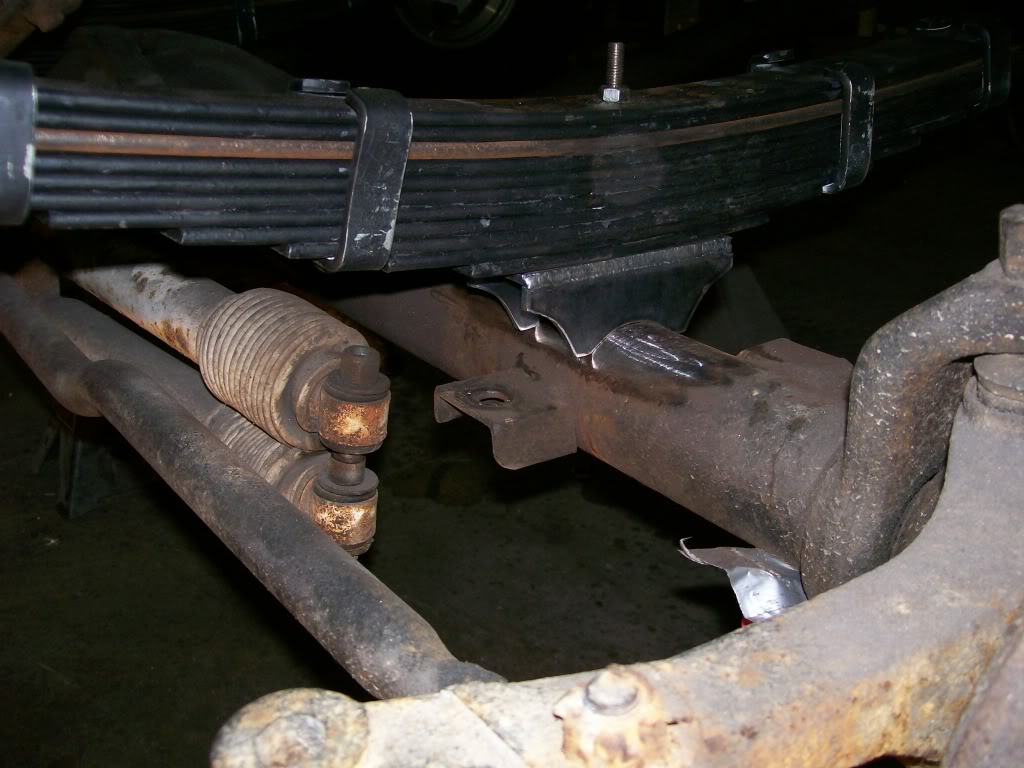
Here is the perch that I made an educated guess about what it's height will be. Once I made this perch, even it is the right height, I wouldn't use it. As I did with the shock mounting brakets on the rear axle, I'm not happy with it's design, it will be tossed. Don't get emotionally attached to something that doesn't fit the build. What I dont' like about this perch is I want more contact where it meets the axle. I've already made a new one and it has nearly a 1/2 inch more contact on each end. That's nearly another inch of weld per side.
12-2-2011
Well look at the two of you stepping up and designing gusseting.
You're on the right track. Lets think of the weakness of something built. Let's take the spring perch in the picture. Imagine it was welded in place already and there were no more pieces added to it right now.
With a hammer you wanted to try to break it off the axle. If you hammer upwards at the front, you'd be fighting against the full welds on both sides. Same with the rear, still fighting the full welds.
Now try from a side hit, since most of the welds are on the outside of the perch sides, the only weakness is the side that is opposite of the hit. And the same with hitting from the other side. The weld zone is weakest when you try to roll the material over the top of the weld.
In the case of breaking the welds, I would cut down the center of the perch and hit each side from the center, rolling each side over it's weld.
Ok. so the idea is to build a product that under stress, will not create a situation that will allow itself to roll over it's own weld.
With this concept, you guys are very correct in your idea. When you weld a brace that goes from one side to the other you eliminate the possibility of the perch twisting and rolling over it's welds.
I will weld in a cross brace when done, but I will go from the center-up. In this way I will tie both sides and the top all together to eliminate the twisting effect.
Yes, partially due to trapping and containing crud and having a rusting issue.
It is pleasing to have you guys get involved, I appreciate it.
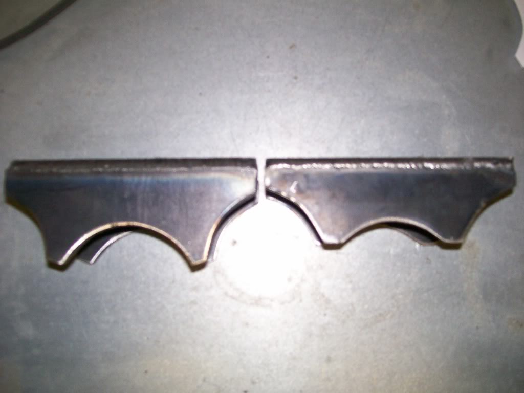
I mentioned I have made a new perch with more weldable surface, here is the new and old design.
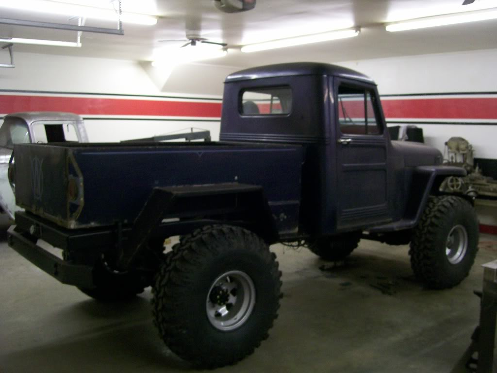
I still have many more pics of suspension work, but I just assembled enough to at least get a look at the stance with the new perches in place. Figured I show the final stance.
12-3-2011
J-Quad, ouch, that had to hurt. I can imagine once the launch failed, then came the time of looking underneath to check out the damage.
FinnXJ, thanks for the compliment. It means alot that people have been learning from this thread. I'm no pro at this metal work, but I'm happy to pass on what I can to the younger generation. America was build on what is now the lost art of hand crafted work and fabrication, hopefully I've put the concept back in the forefront of some people's minds.
I'm still dealing with getting the passenger side perch set-up, without getting the passenger side taken care of I don't have the measurement height to build the drivers side to match.
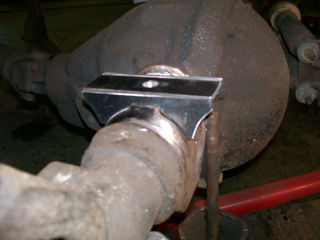
Sooooooo, I'm back to cardboard again. Once I ground down the roundness to a flatness I started cutting cardboard to create a mock-up perch. Once I made the perch in cardboard I scanned the three pieces, 2 sides and the top, to the torchmate and cut the pieces in metal.
Here is the cardboard mock-up.
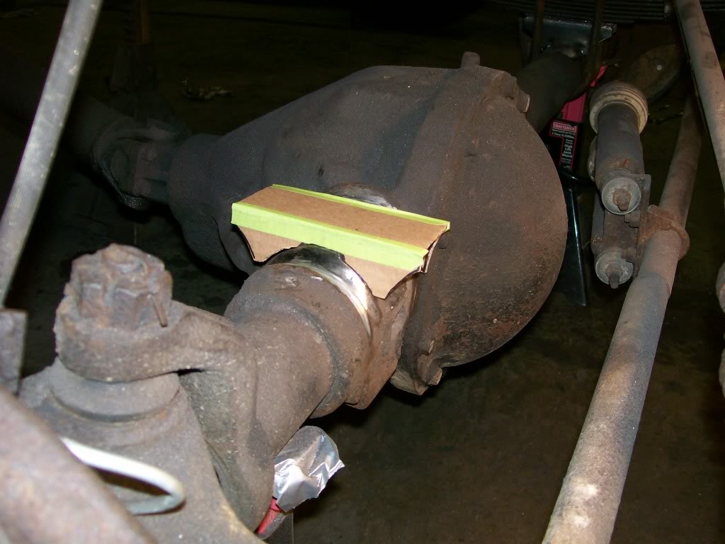
Now the pieces after being cut. There is a difference in the design of the perches from how I've built the other ones to how I've built this one. This one I had to weld the side plates to the axle first, then weld the top plate to the sides plates. This way I could get the welding done, otherwise there's no space to weld to the axle after the top plate is welded on.
Another difference is; usually I place the top plate on top of the side plates. This way the weight of the vehicle to transfered from the top to the sides, then right to the axle. If I were to have it where the top plate fit between the side plates, the weight would transfer from the top plate, then through the weld, then to the side plates, then to the axle. The welds would be the weak link.
Ok, look closely at the metal perch pieces, the top plate is now between the side plates. Normally as I mentioned above, in this design there would be a weak link. But in this case the weak link eliminated. Although the top plate is between the side plates, most of the weight will not transfer through a weld, the weak link. The top plate actually sits directly on the flat that I created with grinding. The side plates now just stabilize the top plate, not to carry the load of the vehicle.
Ultimate classic truck right there
Posted by CCmyVW on 12/26/20 @ 4:17:42 PM