You must be logged in to rate content!
11 minute(s) of a 377 minute read
2-16-2015
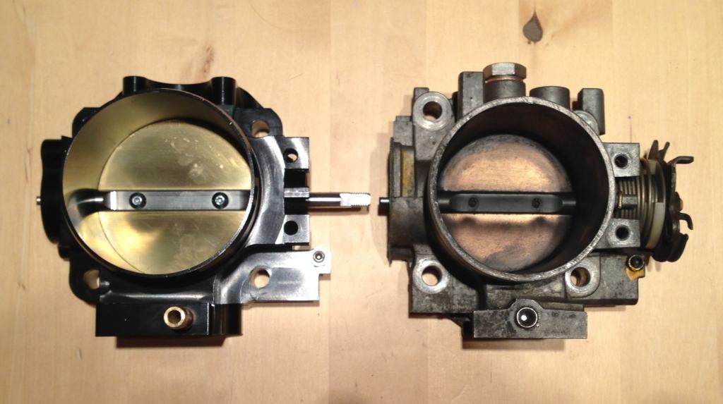
70mm Clockwise Motion Throttle Body
Some of you might recall that I had previously bought an OBX 72mm Throttle Body, well - it was a piece of cr4p - and returning home, after getting it dyno'd last (two years ago) I couldn't get it to idle as air was p!ss!ng past the throttle plate. So I had to replace it with the original 62mm TB, this was robbing the motor of power as the supercharger is quite sensitive to restrictions up stream - approx 20hp missing (based on back to back test guys in the US had done).
Recently I had decided I want that missing power back and tried to get the throttle plate fitting better. However after much fettling and f-ing around it still leaked like a *******. the problem is that I couldn't do anything about the gaps by the spindle which were 5thousandths of an inch both sides, now this might not sound a lot but when there's 2litres of the vacuum every 2 revolutions you be surprised how much air it can suck through those tiny gaps
I had been searching the tinterweb for some time trying to find a suitable 72mm replacement but couldnt. I chanced upon this 70mm Clockwise Motion TB when doing a search, I ordered it from http://r-motion.co.uk/. Great service and very quick to send the part once the order was made. These guys look to only stock top notch parts and Mike, the owner, races, so knows his sh!t...
FYI - anyone trying to Google Clockwise Motion wont find any way website, these are the people that make the baffled sump insert that is used in the VTEC Zcars conversion and are very popular in the Honda scene. Years ago I spoke to Ian @ Clockwise and I got the impression that he was getting lots of calls from people asking stupid questions. I know everyone has to start somewhere but if you're constantly plagued with newbie questions your gonna get cheesed of with it. From what I can gather they are still an operating company but only deal with distributors now.
Anyhow, I also decided that in an effort to compensate for using a 70mm instead of 72mm that I was going to improve the cold air intake. I am changing from the old 3" up to a 4" intake right up to the throttle body. This is throwing up its own problems, firstly the old setup I had for the throttle cable cant be used as you physically cant fit it on the TB with the new 4" silicone adapter on there. So the old grey matter got out into use, in an ideal world I would have made a 3D model and got it machined out of a single block, buts that expensive and frankly I couldn't be ar53d to get quotes and wait for it to be done. So I whipped up a new cable holder/adapter/turn around a corner thingy majig....
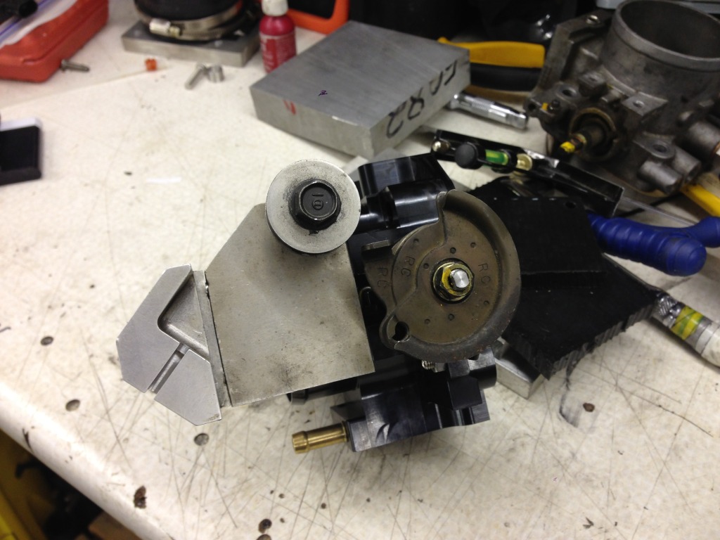
So here's a few photo's of the old TB with the old throttle cable holder (Martin AKA Rust and Oil (Minibusa Van build) made the nicely machined part for me) the rest of the ghetto setup I had made myself - in a rush I might add....However what I ended up with saved me having to order a longer cable.....
Old Setup - on new TB:
New Setup:
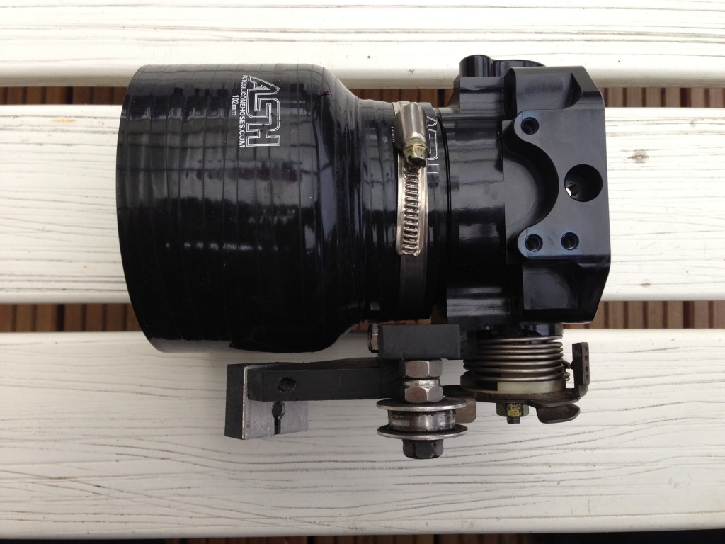
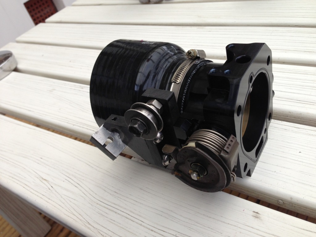
For the eagle eyed among you, you might be wondering how I pass the cable through the acetal part of the mount - if you disassemble that part of the mount you can slide the acetal part over the cable and then reassemble, making the hole where the cable end sits much stronger than with a slot in the side of it for the cable to pass through during assembly.
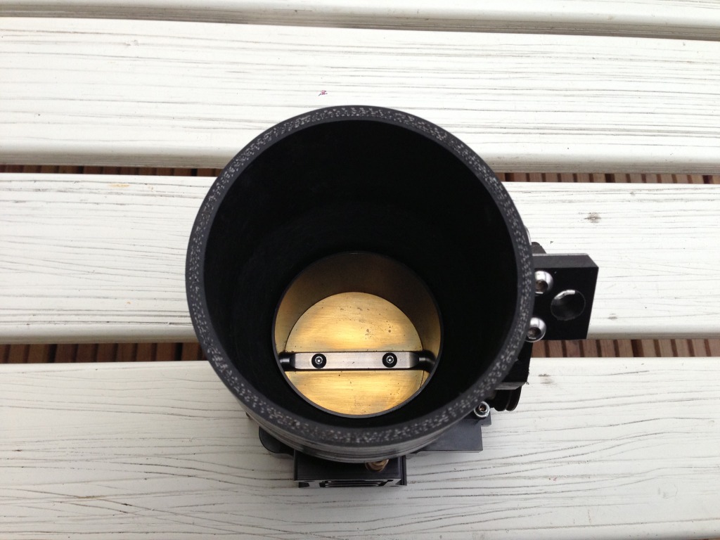
I also realize that the air flow, pre throttle body, would be much better if the transition from 4" to 3" was more slight, ho hum.....
Now I have to work out how I am going to make a true cold air box and feed it with multiple 3" cold air pipes....
More to come later - waiting on bits now.....
.
Oh, here's the old TB verses the new: its defo going to be worth swapping them
2-17-2015
From what I can gather, from the reading I've done on the US forums for supercharging, once the air is compressed it wont make a massive difference, however restrictions up stream of the SC do. The Rotrex kits tend to keep the OEM throttle body, sometimes they go for an RBC manifold (flows better than original) which can be mated to a 70mm TB but I haven't seen any with crazy big TB's like you get on some of the, TB first, big Whipple/Lysholm Twin Screw or Eaton TVS chargers (sometimes 90mm or big oval TB's). I think in the case of the Rotrex kits they try to keep the piping sized to what the outlet from the charger is and this is similar to the OEM TB.
The problem with bigger TB's is town driving and light throttle as they let in a hell of a lot more air on very small throttle movements from closed. If its a track car then no worries as you'll either be wide open throttle or braking.
One very good thing about DBW TB's is that you can have big TB's and program really small amounts of movement for the first half of the throttle pedal action so town driving isnt really affected.
If you only have cable - like me, you could try using a snail cam on the cable to get constantly rising rate of opening or Jenvey utilize a parallelogram arrangement to get the same effect - I am gonna invest in a bionic foot, hey if its good enough for Steve Austin (showing my age now)........
I think I got a bit off track there....
Edited for typo's
3-10-2015
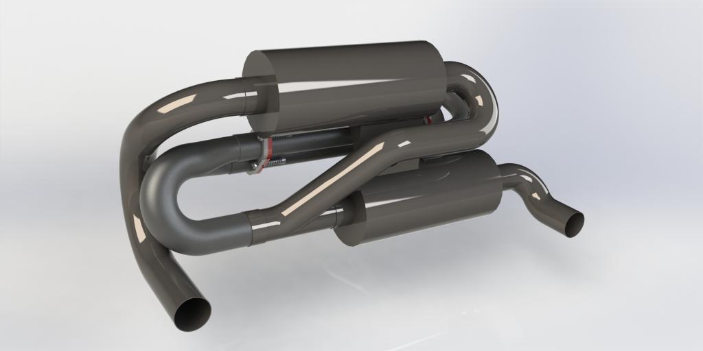
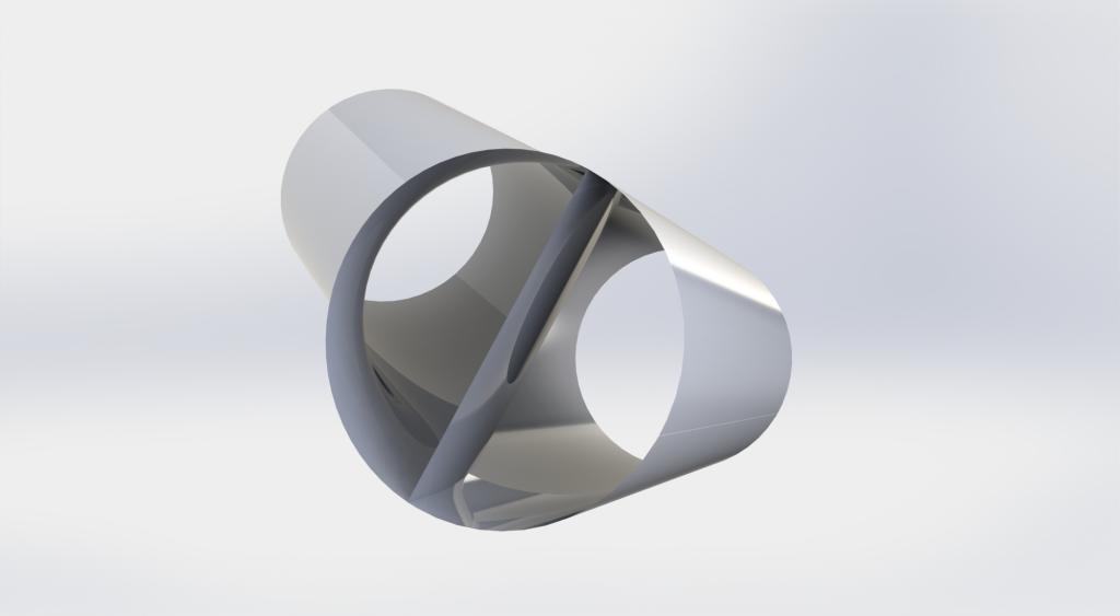
NEW EXHAUST SYSTEM
The fun has begun. I got all the bits , bar one (the flat plate to do the splitting) cut for the 45degree splitter for the new exhaust system, just need to pin down my mate to get them welded up.
As you all know I started out with the 3D model, I then flattened the parts out to make paper templates:
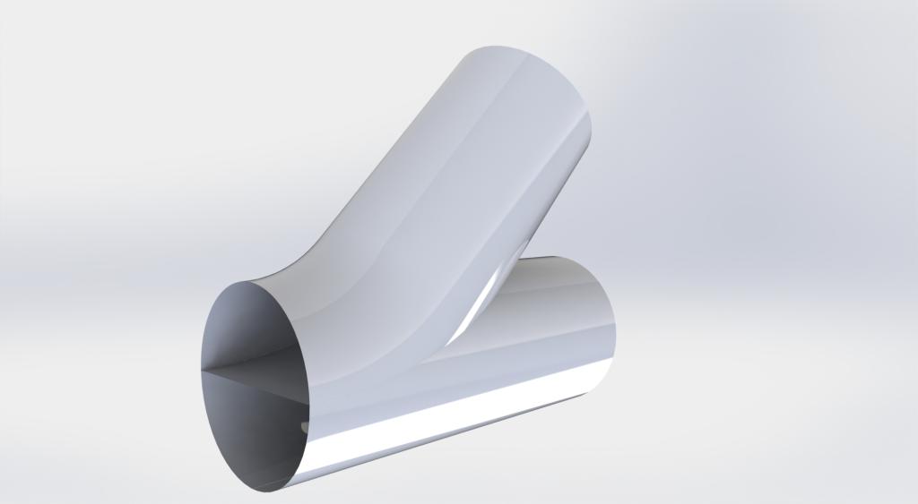
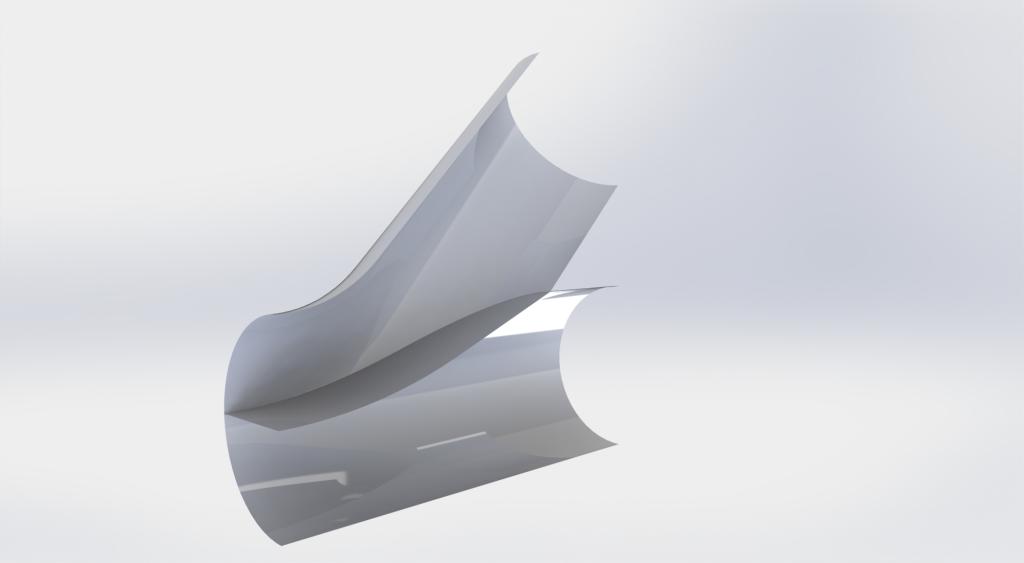
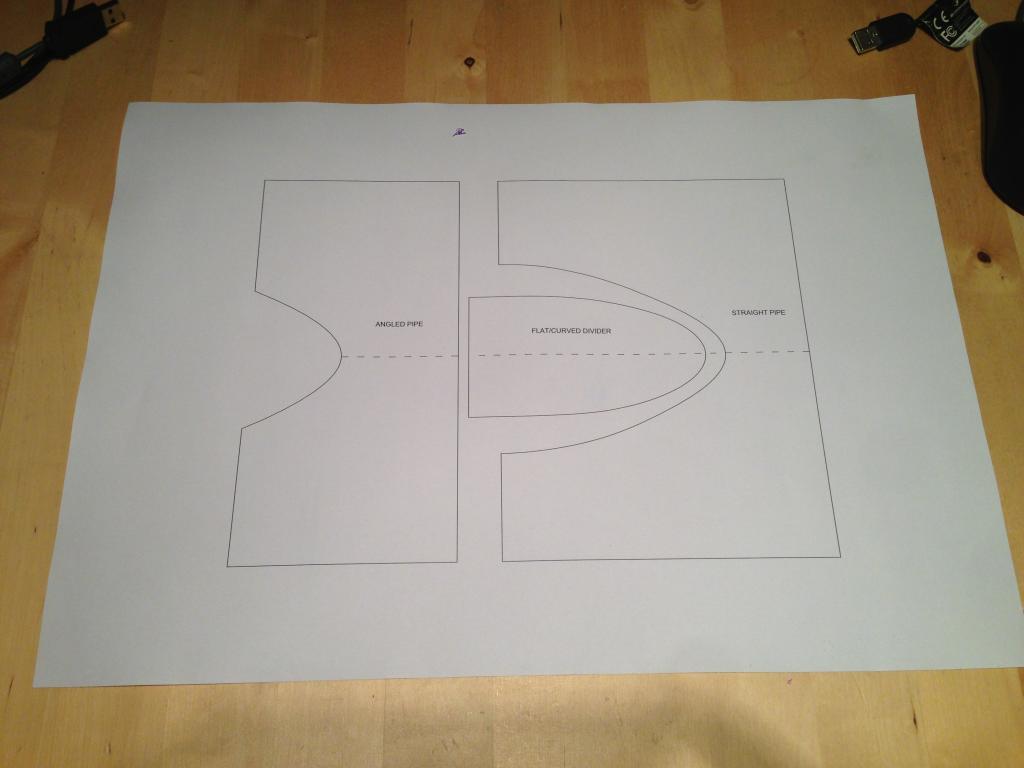
Then cut them out and wrap them round the pipe to get the shapes required:
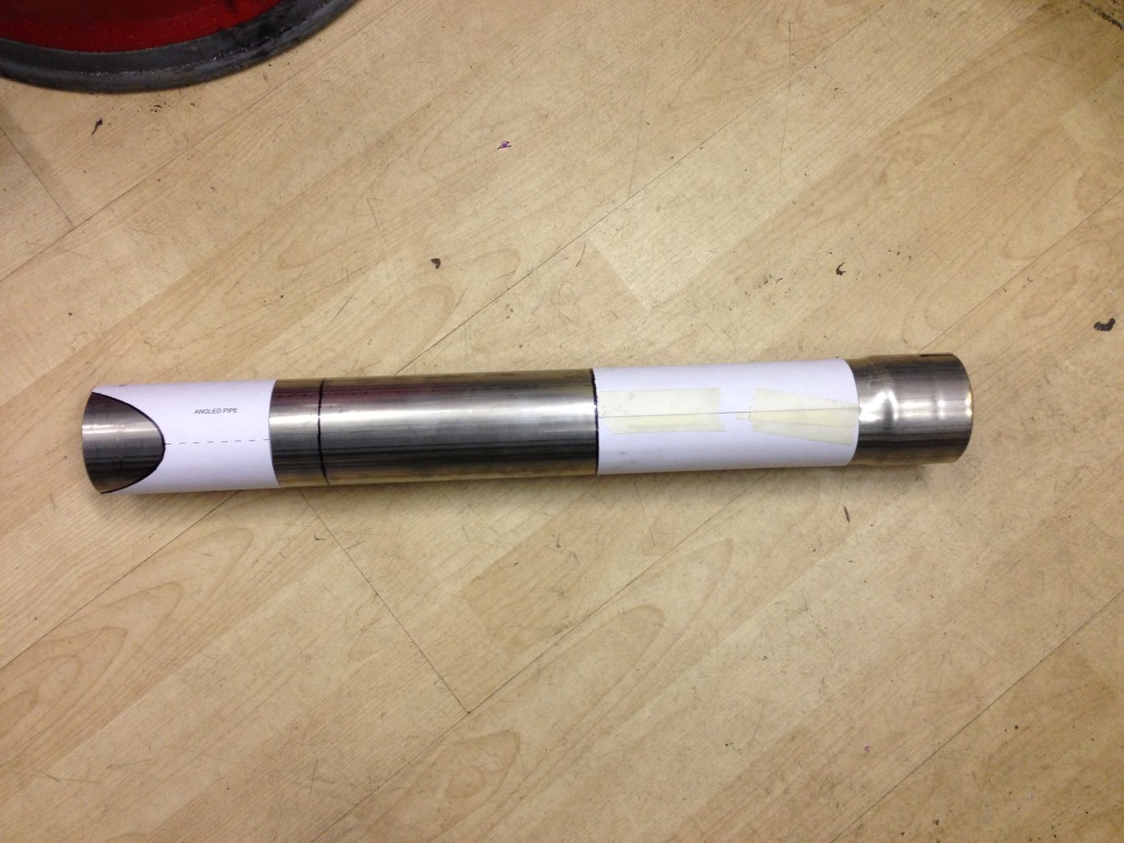
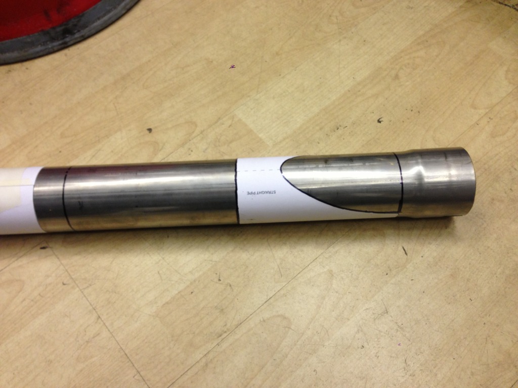
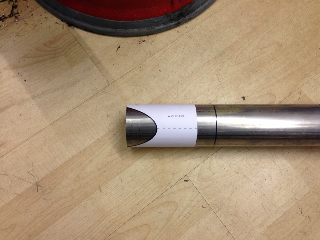
Then cut them out - 4" angle grinder with stainless slitting disc works a treat.:
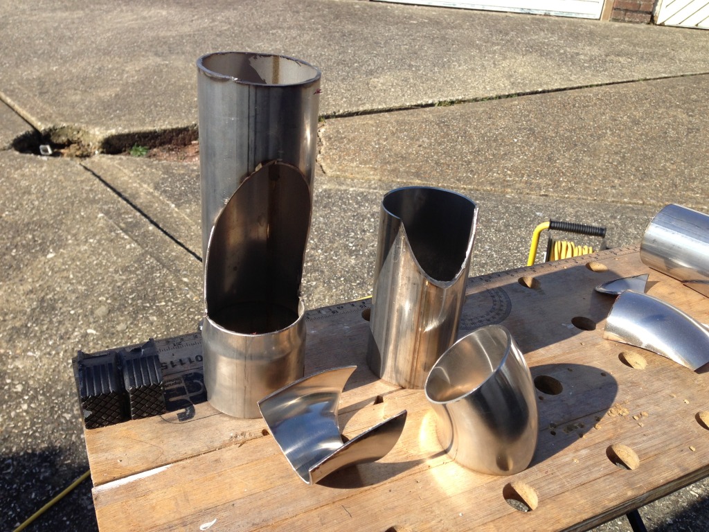
Then bring the puzzle together:
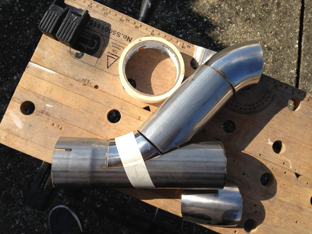
Really need to invest in a TIG welder then I can do all of this myself.....
AUTOMATIC THROTTLE BLIPPER
The long winter nights have got me thinking about making my own automatic throttle blipper for downshifts - before any one says anything, yes I could learn to heel n toe but I am too old to give a Monkeys about it and want my life made easier.
I have seen it has been done by others, most noticeably a guy on the K20.org forum called MacLotus. He, however, got a company to make the stuff for him but it was initially his idea. His idea is a different take on it, than mine, and if you google DIY Throttle Blipper his system will come up as he posted it onto every forum he could. The finished product can be bought here: http://flatshifter.c...atshifter-blip/ you can see a link at the top of the page to a K24 Lotus.Now if you've got that kind of cash hanging around then that would be great - I dont...and I like making stuff myself.
So I am tackling my problem a little differently from the flatshifter product. They use fancy pants strain gauges in the gear linkage which cost a lot of money, a control box and a linear vacuum actuator, only blipping when the brake is applied and force on the gear lever. My system will have a fancy pants control box made by me (it wont be fancy at all), it is using two proximity switches that will be mounted at the brake pedal and clutch pedal and a solenoid with a load of grunt to do the blipping. I am able to control a delay time before the ON period and the length of the ON period when the solenoid will be activated. The whole system will be easily turned on/off so as not to look like a t!t in town.
My system will be activated when the clutch is depressed, however before that can happen the brake must also be applied, so both feet are being used on the brake and clutch, leaving the throttle pedal free. So this is where I am going to make the solenoid work. I've got a bit of space in the area around the top of the throttle pedal and as this is where I have connected my throttle cable it makes good sense to use it.
The throttle requires 30mm of linear travel to go from closed to wide open throttle, I only have 10mm of linear travel in the solenoid and in the interest of keeping things a simple as possible I dont want to be adding fulcrum points and levers so am going to need to get a hold of the throttle pedal closer to its fulcrum to get approx 2/3 open throttle which should be enough to get the revs up to help slip the lower gear in.
Normally at this point I'd be going on about how I'd made a super duper 3D model of it but I havent, not even a 2D sketch in CAD.......
I have however been working on the electronics side of it to make sure that side of it is possible before I go ahead and model the solenoid and its relationship with the pedal. I put together a basic test of the first round of parts and have got some really good results. I have some digital timers coming that I can control to 0.1seconds that will help me to fine tune the final product.
Here's a video of the initial testing of the electronics, note there is a slight delay before the solenoid is activated and that both switches need to be activated to get the system to work:
Now I need to go away and design the interface for the solenoid/throttle pedal.......more to come later......
Wow this is amazing build!
Posted by Diggymart on 2/3/20 @ 4:10:14 AM