You must be logged in to rate content!
10 minute(s) of a 377 minute read
11-16-2011
SPRUNG EXHAUST FLANGES
I have been suffering with lots of exhaust fumes in the cabin of the car which I can only put down to the sprung non gas tight exhaust fittings that are used on the exhaust system.
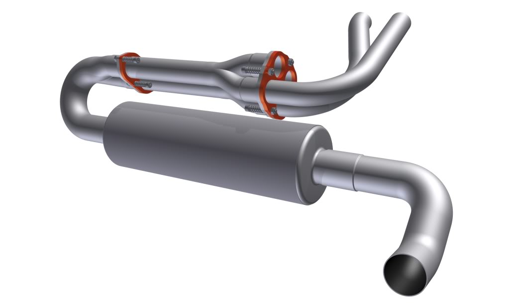
So I got my thinking cap on and what I am about to show you is the 5th revision of the design. I modelled one of the headers as thats all that is currently required and their compound angles are tricky to model so I am saving the other header pipes for a rainy day. The two Y-pipes as I am calling themn the 2-1 Collector, the Silencer and finally the Tail Pipe.
You might think this over kill but I had to model the whole thing so as make sure there werent going to be any clashes between the header flanges and the silencer.
I first considered amking the flanges solid and adding a flexible pipe to the mix but that wasnt going to happen due to the diameter of the flexi pipes. I was also advised even though I have pretty solid engine mounts that solid flanges would fail as the vibration would shake the thing to pieces.
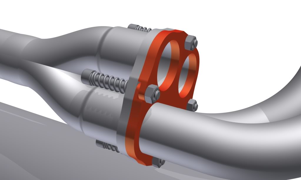
So this lead me to think of sprung joints but also with a flange, still utilising the pipes sliding into one another. Then I had to work out how to use the least amount of bolts and springs so as not to over-do it. I had to consider how to ensure that all plates were being held using only four bolts per set of flanges - cracked it though.....
So the .dxf file is off to the laser cutters and I hope to have them in my hands fairly soon.
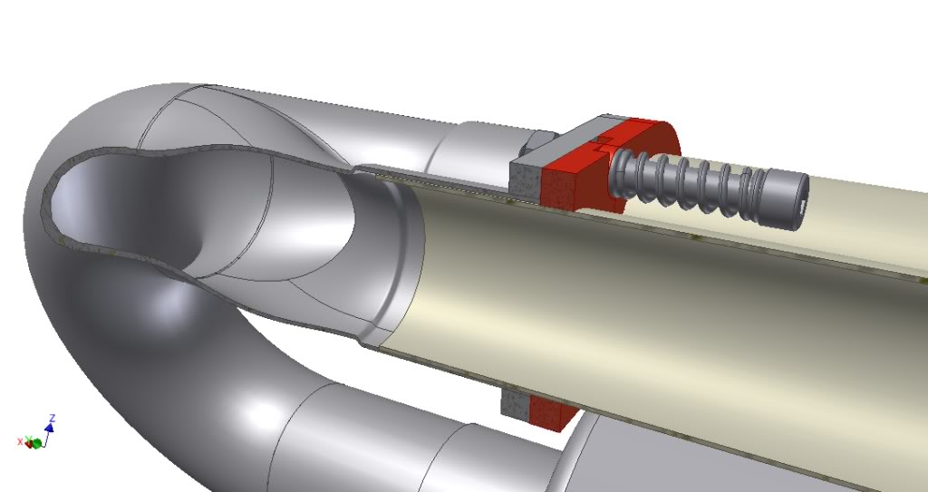
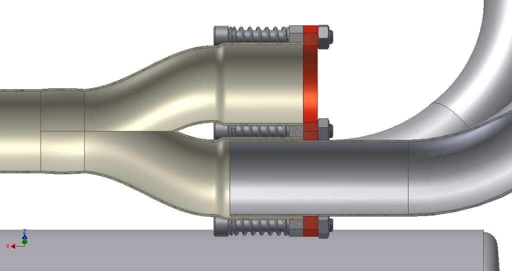
As always here are a few renders of the work: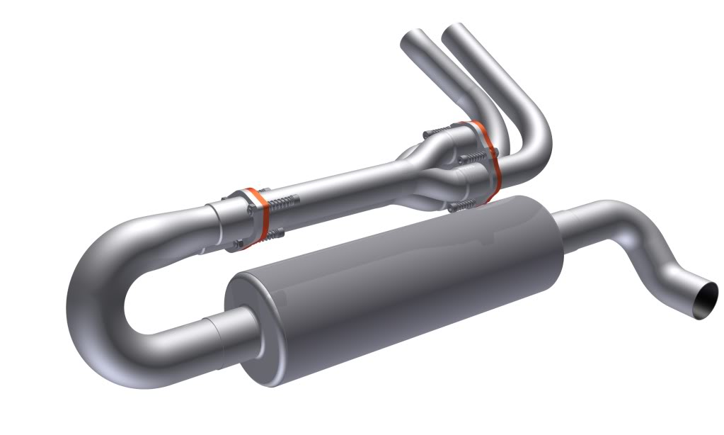
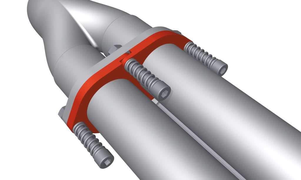
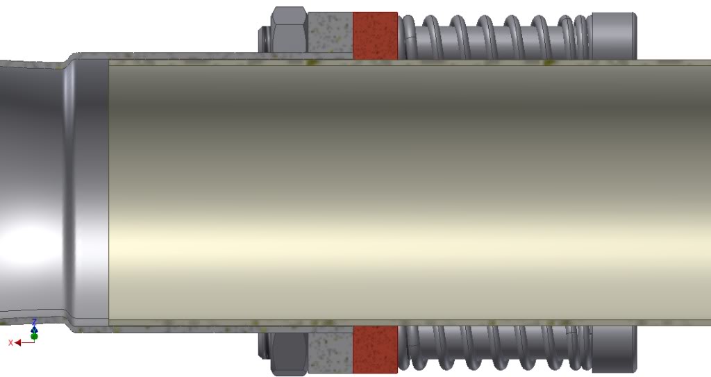
Some cut through views to show the pipes slid inside one another: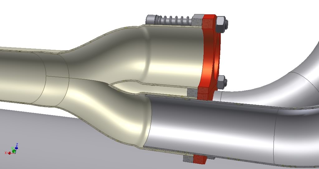
YOU SAW IT HERE FIRST
11-17-2011
Hi Al
I use Autodesk Inventor for the drawings.
The bolts are simply Stainless Steel M8x60 with a 2x13x35mm Compression spring, the flanges nearest the nut are threaded and the nut locks off the bolt this way you can set the amount of compression on the spring/flange.
Below is one of the few pictures I have of the exhaust when I first got it, you can see that the pipes simply slide into on another and are held together by a tension spring that clips onto two loops either side of the pipe mating - this is regularly used and is a good cheap way of building exhausts, only down side is they leak.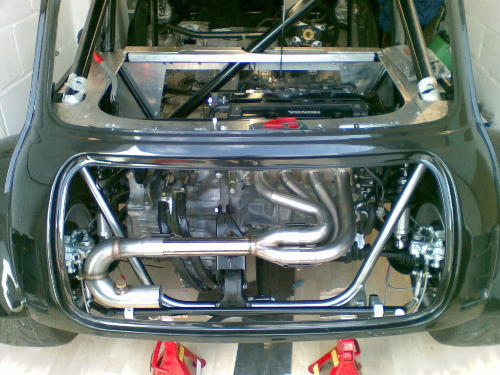
11-21-2011
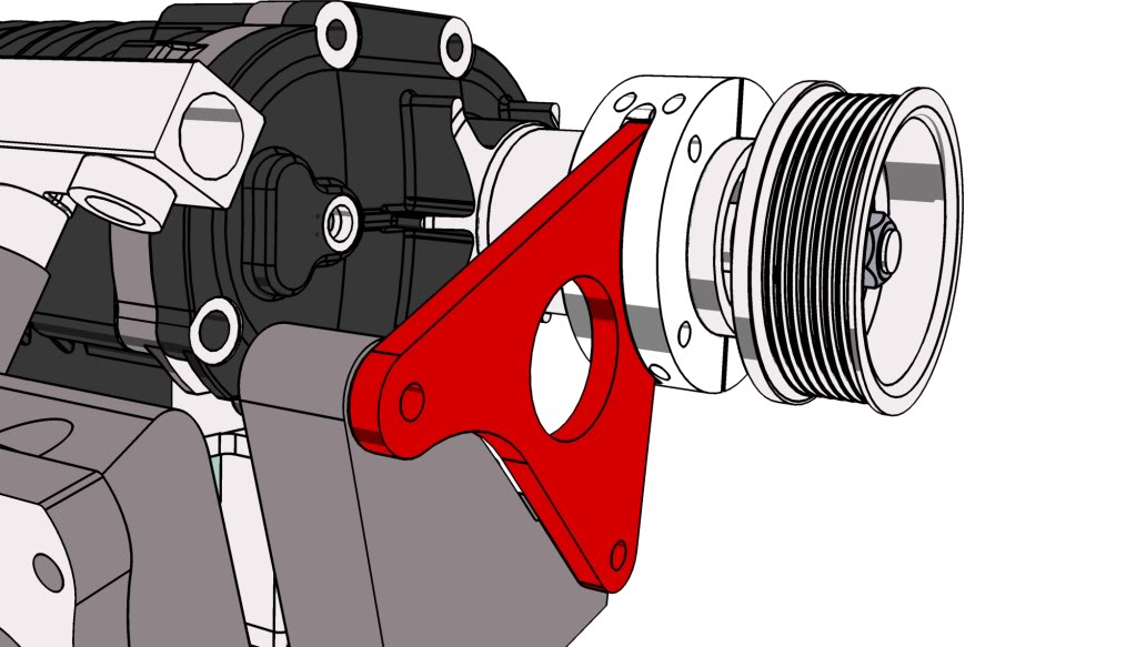
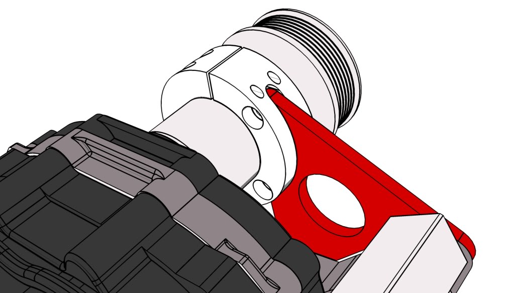
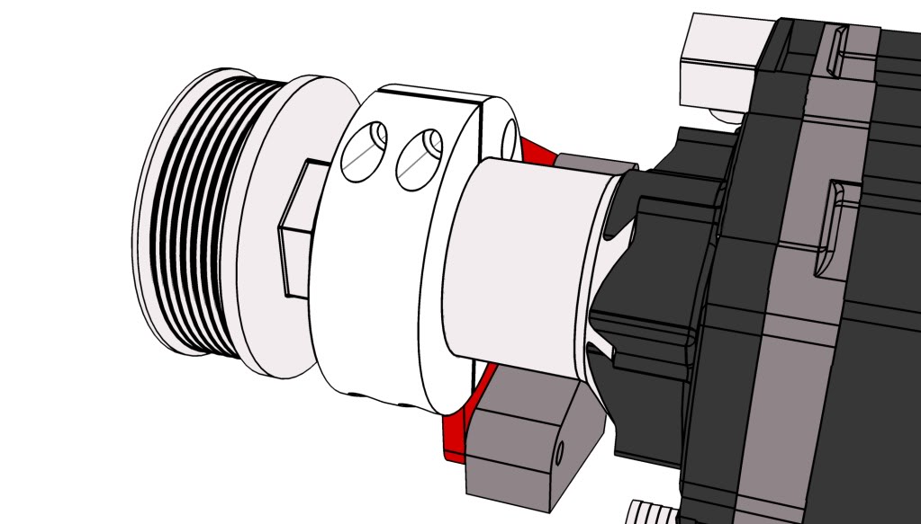
Supercharger Snout Clamp
Another one of my winter mods will be a snout clamp to help with the extra forces that will be placed on the pulley and supercharger when the blower starts to be spun faster. Again I have been through a few design changes with this one but settle for what you will see below. I have the billet for the clamp sat on my table in front of me and plan to get some machining done asap, with the help of my good mate Stevie G.
So here are a few renders of what its going to look like, its a bit chunky but I might cut some fins into it to help dissipate some heat as the snout gets really quite hot, due to the deep groove bearing being used.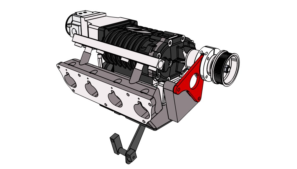
I hope to soon be able to show you the real thing of some of these parts, but even more I want to get them on the car and get it running again.....
11-23-2011
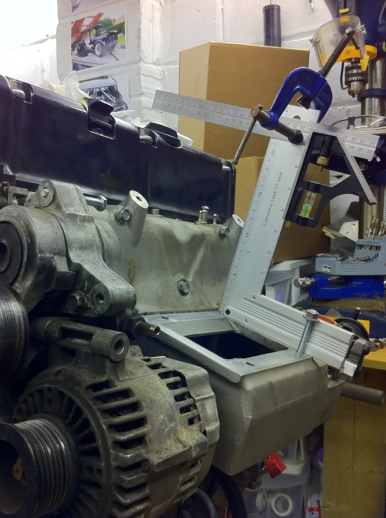
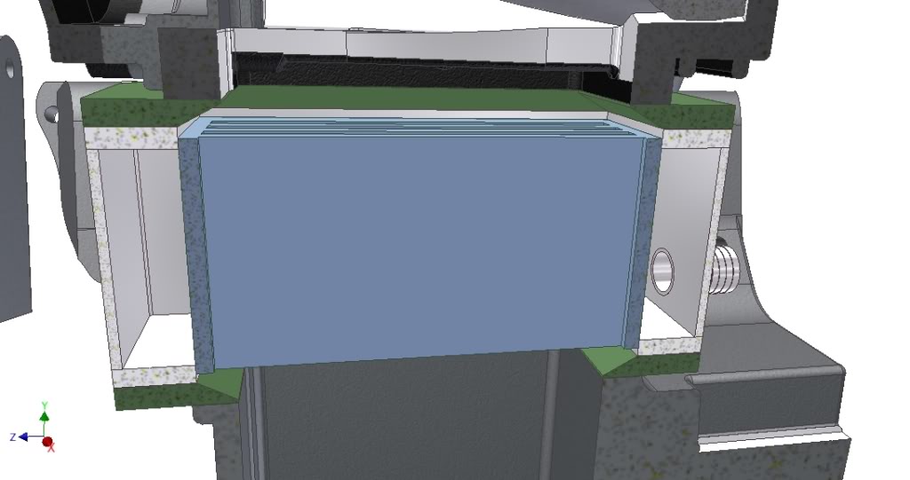
So it looks like I am going to have to put a little lump in my nice flat parcel shelf - bugger....on the plus side it means I can go from a 2.25" intercooler core to a 3". I think thats a fair trade off.
I had a measure up of proposed components and then went and got my ruler dirty checking it all out, Looks like the very top edge of the throttle body is going to be 20mm higher than the highest point of the valve cover/oil filler cap, which in turn is roughly 10-15mm higher than the parcel shelf.
For those that are intersted heres a couple of photos showing how might the charger will sit: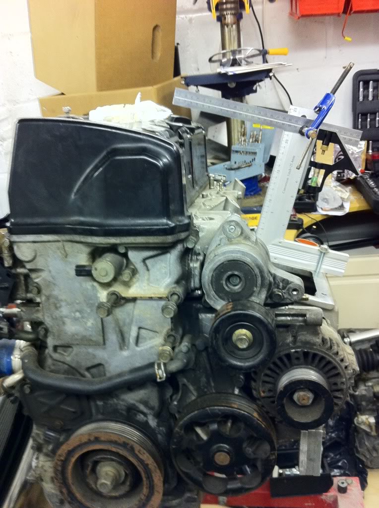
11-25-2011
It all jut got a whole lot closer as well as after Bell received numerous revisions from me they decided (on the last revision where I thought everything was good) that the opening on the intercooler need to match the core, where I had it stepping from the sizee of the output of the charger to the size of the core. So it now looks like I am going to have to add adaptor plates to the mix to cover the size difference between the core and the charger - well annoying....and makes it sit another 16mm higher..... parcel shelf lump getting bigger......
As you can see below it is a perfect match width ways but lengthways in needs to be stepped (adaptor plates in green), oh well, I guess if I dont want to pay for a bespoke sized core then this is the sacrifice I am going to have to make: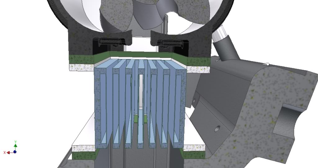
11-28-2011
No news on the I/C yet, still doing revisions in response to comments from the guys at Bell.
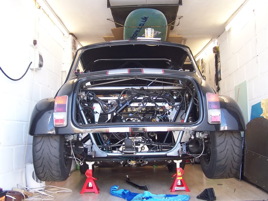
I downloaded some photos from the camera that I took last weekend, they are just to show what state the car is in at the minute and how tight it has become in the garage. I am having to clear stuff away as when its used to try and keep some free surface to work on.
Anyhooo, here's a few photos that might be of interest to anyone wanting to see what the engine bay of a VTEC Zcars mini looks like without an engine in it: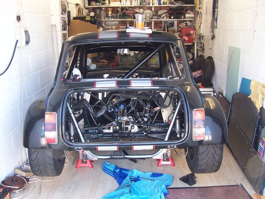
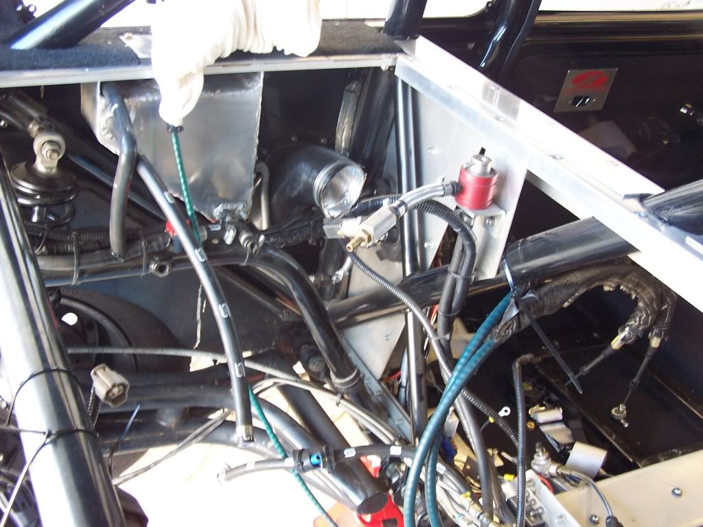
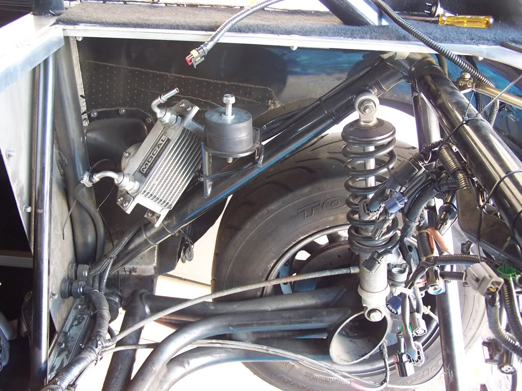
Below is a picture showing the main reason that I took the whole engine out, it wasnt just to change the clutch. The top rear suspension mounts have been bugging me ever since I got the car, as yet they havent failed but I know of some cars that have. So in an effort to eliminate the problem I am going to be making some additional supports to really beef up the mounts and greatly reduce the sheer forces on them. So you can see what I am going on about look at the photo below and you can see that all the force from the suspension unit is trying to make the bolt and its mount sheer from the frame. Since my frame has been made Zcars have beefed up this bit by adding a small rod in the mix to the top diagonal. As I am not intending to strip mine out and have it re-powder coated I am going to fabricate a brace bar that will hold the inner end of the bolt solid, more of that to come: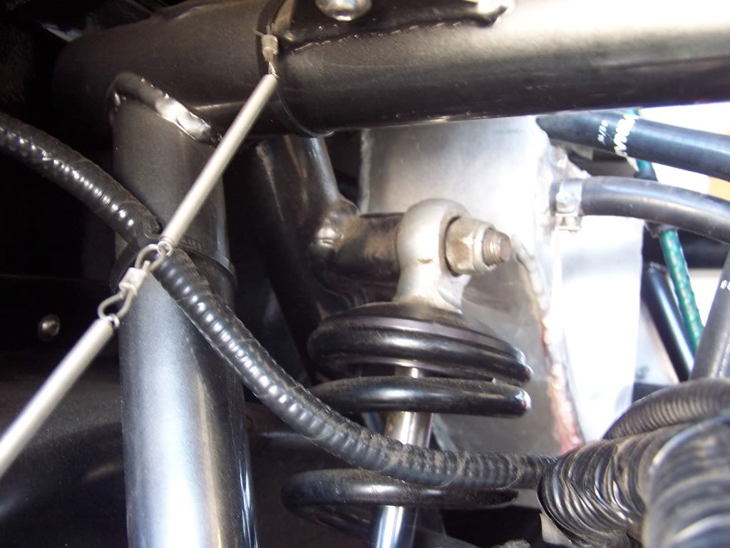
Good old facebook got me the loan of an engine stand to allow me to tinker to my hearts content.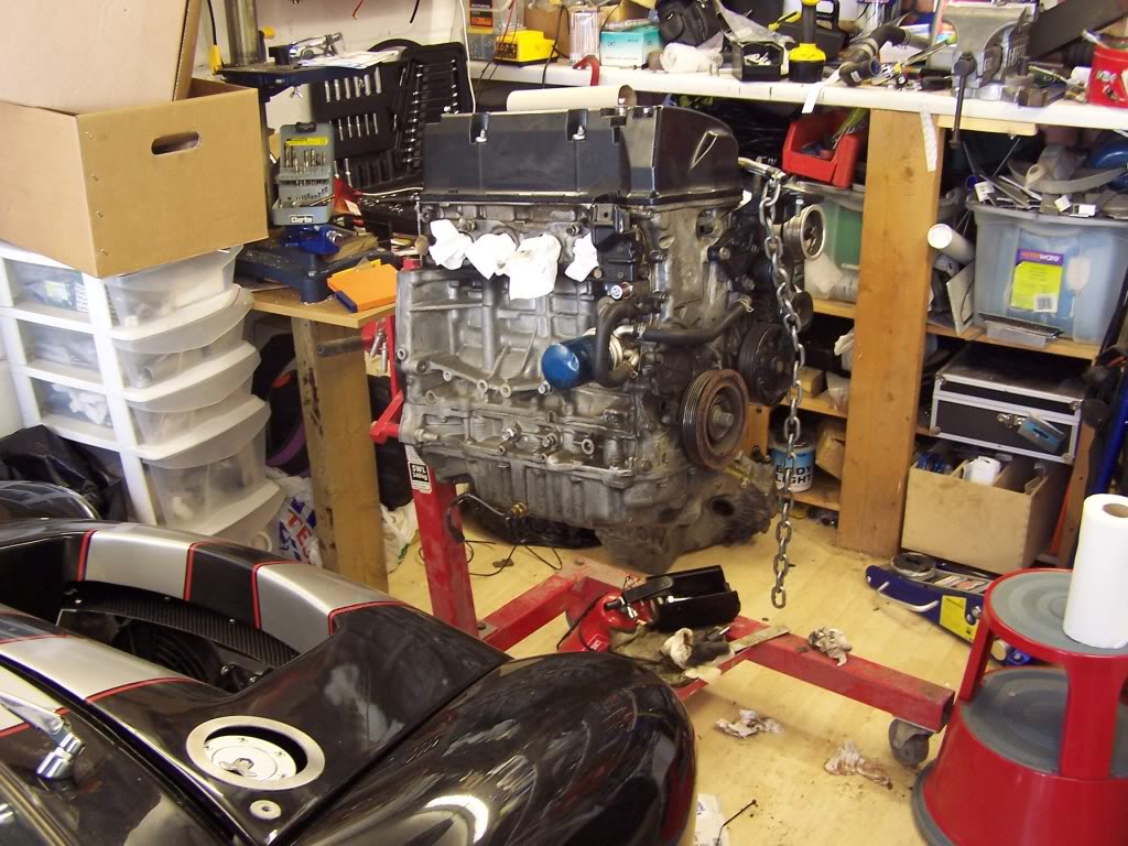
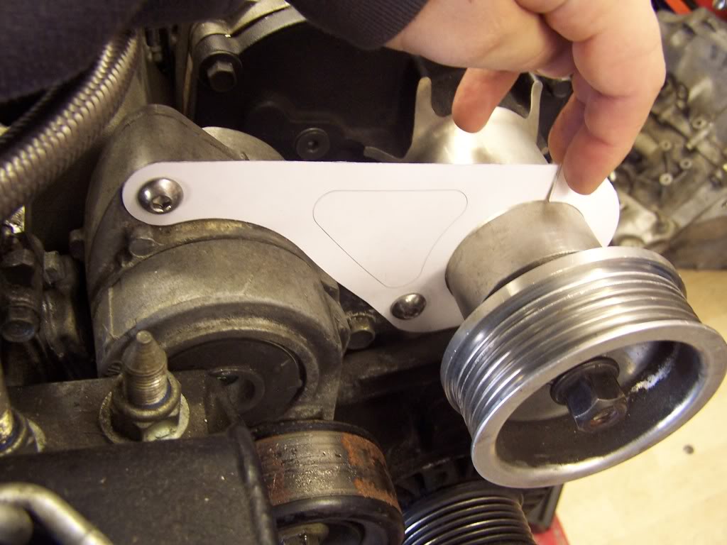
In the picture below is a card version of my first attempt at a snout clamp, before I decided to go chargecooled, the design has definitely come on a long way since this version.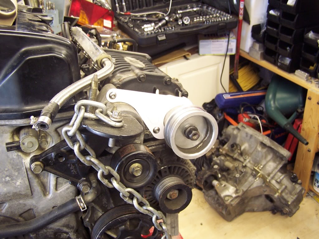
Below shows a broken sensor, its the VTEC oil pressure sensor of which Honda UK want approx £96 for one, I have managed to get one from the USA for £42 inc P&P, genuine Honda part..... Feck knows how long its been like that, the clip just came off in my hand with the top of the sensor still inside it - ooops...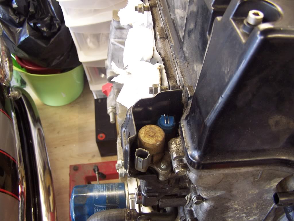
That's all for now folks.........
Wow this is amazing build!
Posted by Diggymart on 2/3/20 @ 4:10:14 AM