You must be logged in to rate content!
13 minute(s) of a 668 minute read
3-6-2012
Now that we have a visual idea of the power valve, of which most illustrations will do, let's see if we can understand this power valve.
In the Holley carb like this one, there are 3 or 4 fuel circuits. They all have to work in harmony and at just the right time to create a power band without hesitation from idle to wide open throttle.
The vehicle, at idle, is pulling fuel through very small slots right where the trottle plates almost touch the throttle bore. As we covered already, the accelerator pump gives us a shot of fuel so we can transfer from the idle to open throttle happens. Now is when we need the power valve. Once the accelerator pump shot runs out, the main jets still need a helper since the throttle plates are open and the vehicle is accelerating.
This is where the power valve comes in, it fills a void between the accelerator pump and normal driving.
By the previous post, take a look at the center one. The end with the spring is where the gas enters the valve. Looking closer inside the spring you can see a tapered end, this male taper fits a female taper, thous creating a shut off valve.
Since there is no vacuum draw on the other end of the valve and the valve is open in this picture, we can assume that gas flows through this valve when there is little or no vacuum.
I mention the vacuum idea, vacuum is once again used to open and close something to work with the fuel flow. Looking at the valve at the right, you can see yet another rubber diaphram behind the metal shield.
Here's the lowdown, the spring/valve side is in the float bowl resting in gas. The other side is in a chamber that is constantly at the same vacuum as the intake manifold.
In a situation where you've got the throttle open, and the engine is trying to catch up with your demand of picking up speed, there is less vacuum in the intake manifold. This lesser vacuum in the intake, is represented in the chamber where the power valve sits. Once the vacuum becomes low enough, the spring on the power valve now overtakes the vacuum and begins to open the power valve and gas now enters the power valve. This extra gas mixes with and travels with the gas already flowing from the main jets. The two mixed together enters the intake manifold as a richer mixture.
Once the engine catches up with the demand, the vacuum in the power valve vacuum chamber raises and pulls against the power valve spring to close the power valve. Now the vehicle runs on the main jets again, til the next time you open the throttle, then the whole thing starts again.
Vacuum, and you thought it was just for the carpet.

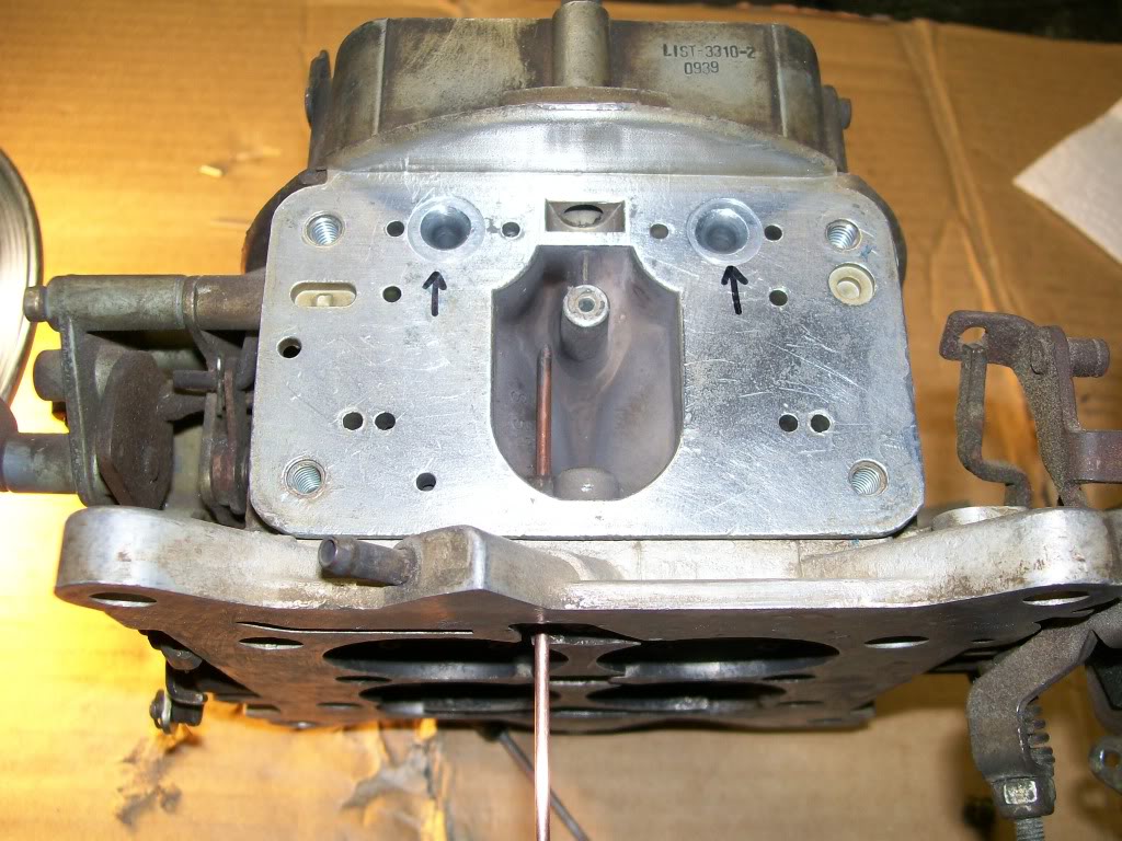
Here is the chamber that the vacuum side sits in. I put a piece of welding rod through the hole so you can see how the vacuum of the intake manifold gets to work the power valve.

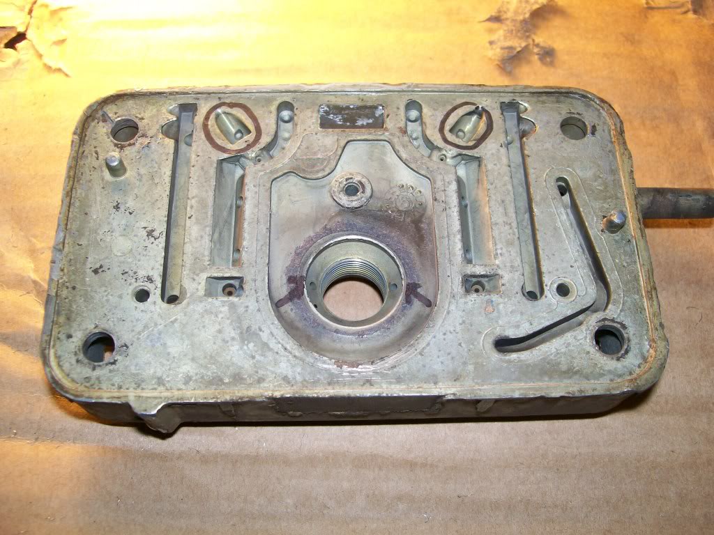
This next picture is to show the path the gas follows from the float bowl then through the power valve.
With no power valve in place, you can see two small holes inside the larger hole where the power valve fits.
The gas goes in the tapered end of the power valve, goes through the threaded part of the power valve. then before it gets to the rubber diaghram, it exits the two slots between the threads and the rubber diaphram bulge.
The gas leaves the power valve and enters the two small holes. Then travels upward, mixing with the gas from the main jets. The gas then exits the metering block where I circled the two spots on the metering block.
Now going back to the upper picture showing the main carb body, I marked two holes with arrows. These are where the fuel enters from the metering block and heads to the airstream then down the intake manifold.
Did someone ask about adjustablity???? Oh yeah, These power valves have a wide range of choices. The main question is, what is the vacuum that your engine idles at. You obviously don't want the power valve opening at idle or too close to just off idle. So the power valve's spring can not override the vacuum supply at idle.
There are also times where you may lug the engine and the intake manifold vaccum will drop also. Once again, the vacuum has to remain strong enough the over ride the spring tension also, or there could be a rich mixture at the wrong time.
One more situation, an engine with a big long duration cam. These have terrible vacuum at idle, so the valve will have a lower vacuum rating before the spring can open the valve.
I'm gonna stop here. Scooter402 is aching to join in on the conversation. I freely give him his input. Getting someone else's point of view is good to expand the situations we all might get into someday.
Scooter402, if you want, lets talk about the metering block also, it's about time to show the secondary's metering block and the metering plate they use some times also.
3-8-2012
We'll get a little farther on the Holley, the only picture I have ready is one of the needle and seat.
To understand the function of the needle and seat is a female taper and a male taper that fits together to allow fuel to enter the float bowl and to shut off the fuel entering the float bowl.
Simply put, the float will rise as the fuel enters the float bowl. Once the fuel raises to a predetermined level, the float pushes up on the needle til it is against the female taper. These two have a precision fit and once they come together the fuel can not pass by any more.
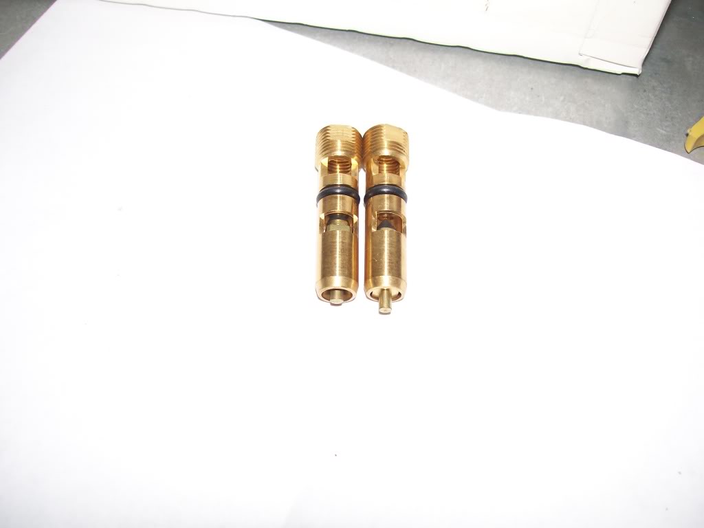
In this picture I have two needle and seat assemblies. One is in the open position where fuel can flow through. The other one is in the closed position, no fuel can flow through.

Looking into the openings on the side, you can see the tapers and which is open and which is closed.
The key to the needle and seat is in the set-up. Although Holley has a fairly easy method of setting the float height. We'll go through it in the next night or two.
In the mean time, anybody wants to get a up close idea of how a float and needle and seat work, we all have one in the bathroom. Pull the top off the toilet. First thing you see is the float, it has a rod that goes to the needle and seat. Although the toilet usually has a small screw to turn to set the level of the water, sometimes it's possible to bend the rod to adjust the height of the water level.
Getting into carburetors is the same. The Holley uses a threaded needle and seat assembly to adjust the fuel level. Some other carburetors require you to bend a tab on the float to set the fuel height.
3-10-2012
The stock Holley parts in these pictures are very similar to high performance parts. The biggest difference in the stock main body vs. the aftermarket HP main body is the lack of a choke horn and the venturis being smoothly blended.
With metering blocks, on the other hand, there are quite a few differences. Looking at stock metering blocks, however, will help ease the understanding of their inner workings before diving face-first into an aftermarket set, and trying to tune them.
Have a look again at the main body picture -- the arrows are pointing to where the fuel enters the main body while at cruise and WOT (wide open throttle). The fuel enters here, and goes through the boosters. The holes on either side of the boosters are passages that lead to the idle air bleeds (outside of the booster passages) and the high-speed air bleeds (inside of the booster passages, next to the bowl vent).
The idle air bleeds and high speed air bleeds are tuneable, but more easily done with aftermarket metering blocks that are drilled and tapped for interchangable jets...once one modifies a stock metering block, it's kind of hard to fill that hole back in if it's drilled out too large. These air bleeds work opposite of fuel jets -- fuel jets give more fuel when a larger size is used. With the air bleeds, a larger size would give more air, or a leaner mixture. These air bleeds are a good way to fine-tune the mixtures when jetting or idle air screws just don't quite do anything to help at WOT or idle.
Now, take a look again at the metering blocks -- both primary and secondary metering blocks are very similar, especially in the performance world. I don't have a metering plate available for pictures, so I cannot help there unless I steal one from Google. On the metering block shown, there are two slots, or passages on each side. These slots have holes drilled into them that lead to the fuel wells. We'll start with the main wells, or the two dog-leg shaped slots with 4 or 5 total holes (that I can count from here, anyway). The hole all the way at the bottom with the notch above it is the idle feed restrictor. This controls how much fuel the engine gets at idle (obviously, by the name of the restrictor ). Holleys notoriously run rich at idle, and this one is the culprit. There is a simple fix for this that I unfortunately cannot illustrate without my pictures...Or a carb taken apart for that matter. I'm really no help here, am I?
This simple fix, and 50wllystrk probably knows what it is, includes a very fine piece of wire folded into a V-shape with wings at the ends, kind of like this: -v-. Insert that piece of wire into the hole, and it will restrict the restrictor, making idle clean and lean.
Next, in the dog-leg slot, there are two holes, one above the other on each side. These are emulsion bleeds. What these do is emulsify air into the fuel. These holes allow an advanced tuner to dial in exactly the fuel mix he wants throughout the entire power curve. This tuning is best done on a dyno, but obviously can be done with the seat-of-the-pants dyno, too. Stock metering blocks always have two emulsion bleeds, performance metering blocks have 4 to 5 of them. Generally, they have smaller bleeds at the top and larger ones at the bottom. Some tuners take a couple of the bleeds out and plug them, depending on the performance of the vehicle.
Next in the dog-leg is a very small hole (right below the circled one) -- the siphon break. This hole prevents fuel from being siphoned over into the boosters while idling, or when the engine is shut off. If your carb drips fuel from the boosters while idling, it's one of two things usually -- the float level is too high, or the siphon break is too small.
Finally, all the way at the top is the passage that connects through to the high speed air bleed.
Now, back to the adjustability of the power valve -- just to elaborate on what 50wllystrk was saying. The selection of power valves out there have only to do with vacuum readings. They are operated by engine vacuum. The correct way to select your power valve is to measure your engine vacuum at idle, after you have the correct timing advance and idle fuel mix. You want a power valve with a number that is 2-3 digits lower than what your idle vacuum reading is. Say, for instance, if you have an idle vacuum reading of 10 Hg, select a 7.5 or 8.5 power valve. The most common one to come with rebuild kits is 6.5. Now, this will work, but it won't be the best for your engine. It will only open when the engine is under a pretty heavy load.
50wllystrk mentioned that radical cams have very poor idle vacuum. Well, mine is one of those cases. I only get about 6-8 inches of vacuum at idle. I have a 4.5 power valve in mine. Just to show off, here's my CJ with the radical idle:

There is also one more adjustment with the power valve circuit -- the size of the PVCR. 50wllystrk had already mentioned this, has arrows pointing to them on the metering block. These are usually big enough, but sometimes not for radical engines. These, when modified, are usually made bigger. I will caution, however, that if one does go and modify these, to be very conservative with changes. Maybe even only do one change at a time.
If I ever get ahold of my pictures, I may do a detailed "mod" thread for a Holley. I built the carb on the engine I posted in the vid above from eBayparts. I had to do a lot of tweaking and tuning, but it runs wonderfully now.
When drilling these passages in the metering blocks or the air bleeds in the main body, an index drill, or finger drill, works best at it. Don't go reaching for your DeWalt 1/2" drive power drill, now! Like I said, use caution and be conservative when modifying these carbs...it's very easy to turn one into junk if one goes too far!