You must be logged in to rate content!
11 minute(s) of a 668 minute read
1-16-2014
As I recall you were looking and or wishing for a welder, I have ask, have you been able get one yet?
A few pages back I fabricated some traction bars for this truck, I had thought about the design for quite some time. I did look and check for a company who sold something for the over the axle leaf spring design but found nobody that sold such thing.
Once I made mine I posted them, shortly after posting them here and another site I received some very positive responses. Reality check....... I may have something here, so I removed the photos and through Legal Zoom I have now acquired a Patent Pending registration on the design and similar variations to the design.
Now I can reload the pictures of them again.
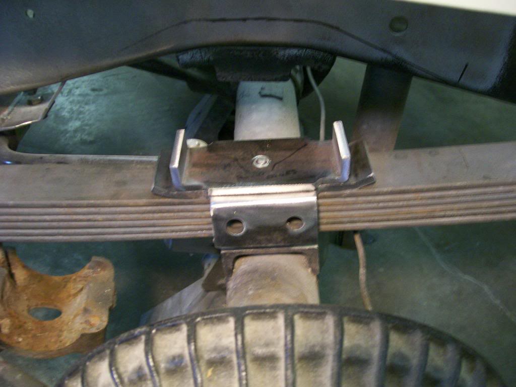
Back to the original leaf spring set up.
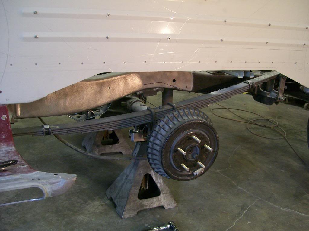
Then the first plate that the side plates will attach to.
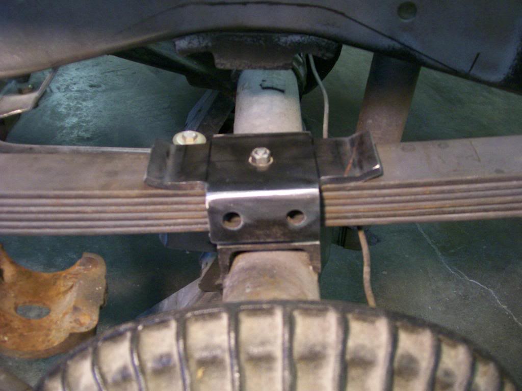
Then the top plate that will reinforce the first plate and will stabilize the u-bolts.
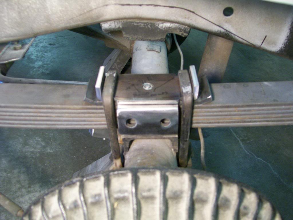
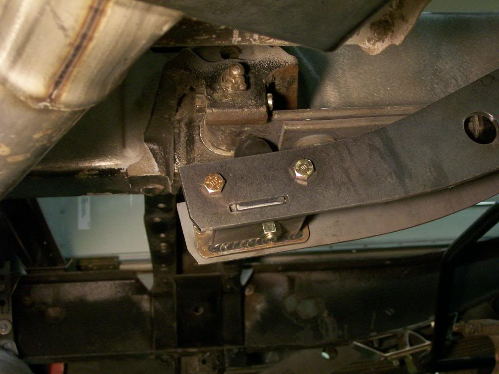
Then with the side plates attached and reaching forward.
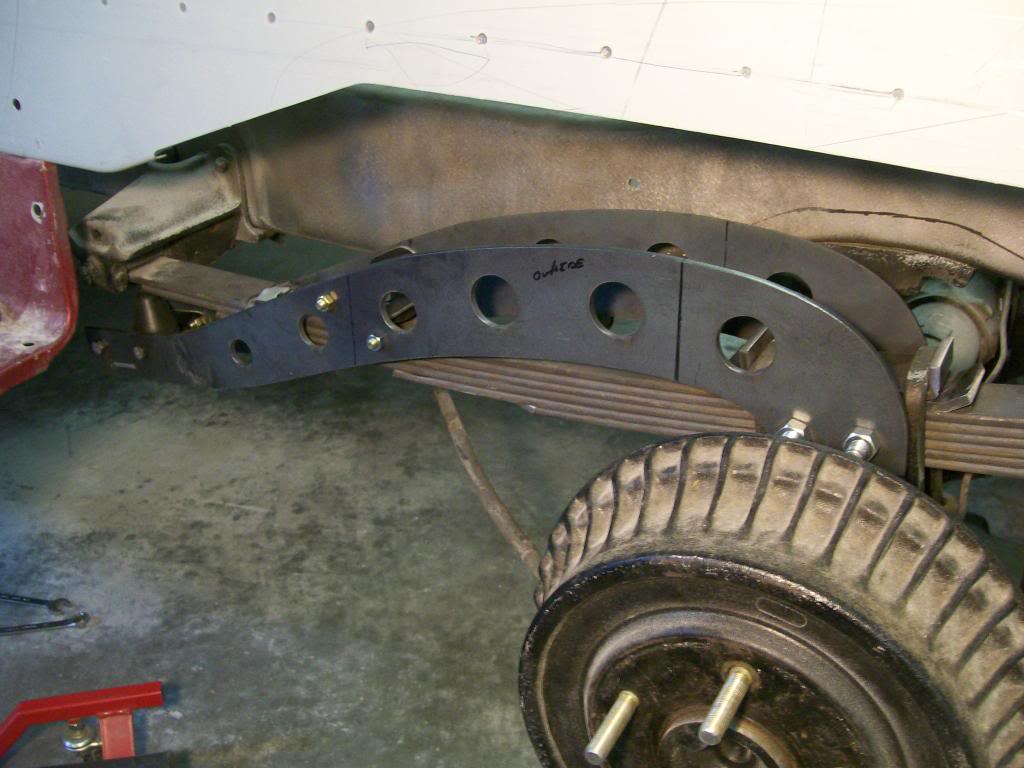
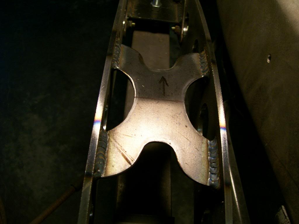
I did get the X brace welded in using my wigweld technique.
A look at where the front rubber bump stop contacts the front of the leaf spring. With the torchmate I've started to cut more tongue and groove fits where I can.
1-19-2014
Ok Jeff88, believe it or not I have gone through a situation where I came up with a product, I made a few, sold a few and was going to pursue sales and marketing. My wife at the time had liability concerns and my enthusiasm fizzled. A few years later the product hit the market and I got nothing, I suspect one of the ones that I sold made it to a manufacturer, I didn't have legal rights.
This time I didn't hesitate, as soon as I realized these traction bars might be something I acted right away. I'd like to get the truck done, buy a Gopro camera, attach it under the truck and show the suspension working with and without the traction bars. If the camera has a good view of the traction bars in action, I may you tube the recording and see where it goes from there.
AK2006TJ, I certainly hope the wife's new job helps pull your finances together to let you get a welder soon, I can tell it's in your blood to do some welding.
I usually like to reply with a set of pictures. This time I'm gonna touch on an item I made last year. It's the front fender emblem, the one I made last year was a test run and I used 1/8" material. I learned some technique but in reality it didn't have the depth I'm looking for. I've gone to 3/16" material and cut another one. I have to get threaded studs attached so I can mount it on the fender.
I drilled and threaded the holes.
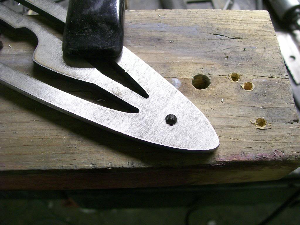
On the backside I threaded a stainless screw and a nut that will hold it in place.
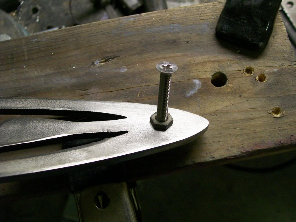
Now flip it over, I left a small valley to fill with weld, this way when I grind it smooth I don't remove all the weld.
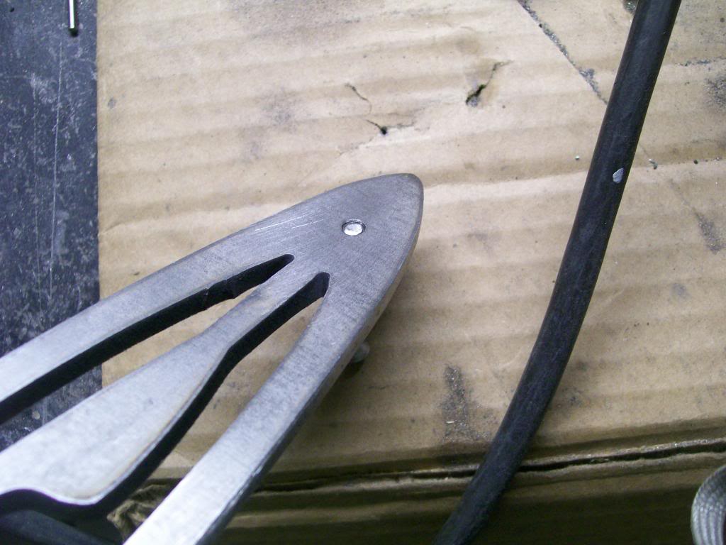
I tig welded this one, I wanted to melt the screw and the emblem together before I added welding rod. Oh, it was my old tig welder that had issues, I bought a simple Eastwood tig welder, nothing special, but it does a nice job without breaking the bank.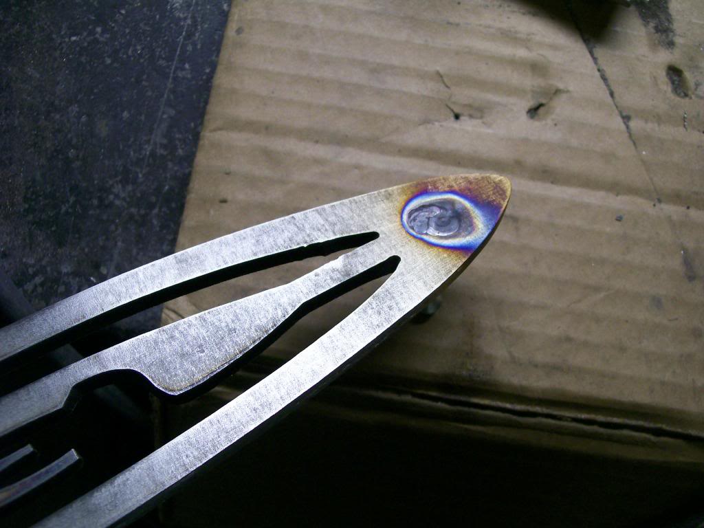
As was mentioned a couple posts ago I used the hand held belt sander to level most of the emblem. It's not easy, I did have to focus grind and sand the welds first, then finish off with the belt sander.
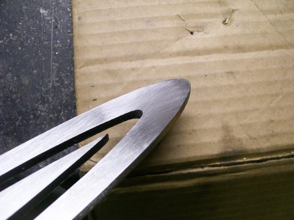
After this it was 240, 400, 600, 1200, 1500 then 2000 grit, takes forever.....
1-20-2014
Sure, let's keep in mind this is sanding a flat surface.
There is a huge difference between rounded surface vs flat. When I did the round bar for the interior work I didn't have to use as many different grits to get to the polished stage. I cleaned the weld with 80, then went to 120 then 400 then 1200. The outside rounded edge allows each grit to be much more aggressive, much more cooperative.
Flat surface is all about the pressure applied. I mounted a florescent light just above the work bench, the good thing about a fluorescent light is it will show all the defects when sanding and polishing that a regular bulb would never show.
The bad thing about a fluorescent light is it shows all the defects. You can be forever trying to polish spots that will never be seen outside or in other locations.
I mention the light source because it is necessary to work through the different grits. With one grit done, you have to watch the scratches left behind as you go to the next finer grit. If you see scratches that are not being effected by the finer grit, those scratches are deep enough to not be removed by going to even finer grits, you have to stay in the stage you're in till the previous scratches are effected.
You have to stay that grit till all scratches are effected by sanding them, once let's say I am sanding with 400 grit and I don't sand to the bottom of the left over 240 grit, if I move to the 600 grit, those left over 240 grit scratches will remain there, each preceding grit has to do it's job before moving on the the next finer grit.
Often times I will sand til I think I'm good enough and move from the courser to the finer ahead of time. This will give me some polish to the surface and allow some of the deeper scratches to be seen, then I'll go back to course paper again and focus on the scratches that appeared.
From the 240 grit to the 2000 grit I use mineral spirits to lubricate and keep the paper from clogging too quickly, I usually have a fan behind me to keep from breathing the fumes while sanding.
Each emblem takes hours to get the finish I want, but I guess if I want unique parts and it's the only way I can get the job done with the tools I have, so be it.
2-25-2014
With the cold weather my progress has slowed a bit but I did manage to get the GM 10 bolt 8.5 rear end changed to a different ratio and installed a posi traction unit form Yukon Dura Grip.
I've covered much of the process with rebuilding the DANA 60, this axle is slightly different in design but the theory is much the same. I know, I know, I keep bringing up knowledge of theory of how things work, but the knowledge will get you into and through a lot of project where others will stop and fail.
One difference is simply removing the axle themselves. Often time we hear the term "C clip axle", this is exactly what we have here. The only think keeping the axles from sliding out the axle tubes is a C clip on each axle.
Once the cover is removed the main cross shaft that holds the spider gears in place has to be removed, once the spider cross shaft is removed the axle can move inward.
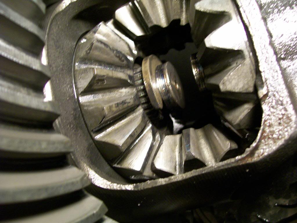
Here is the axle in it's normal position with the spider cross shaft out of the way.
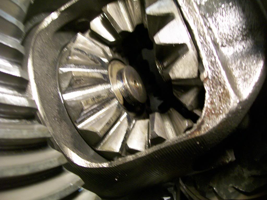
The way it is set into the spider gear keeps the C clip from dropping out. Now when the axle is pushed inward the C clip is able to fall of the axle.
The new carrier and ring and pinion in place. Here we have springs that are keeping pressure against the spiders that are going to create friction in the clutches hidden behind the spider gears. Notice I have marked left and right on the bearing races. I had the carrier in and out perhaps 8 or 10 times to get the preload and the ring and pinion backlash where I wanted then to be.
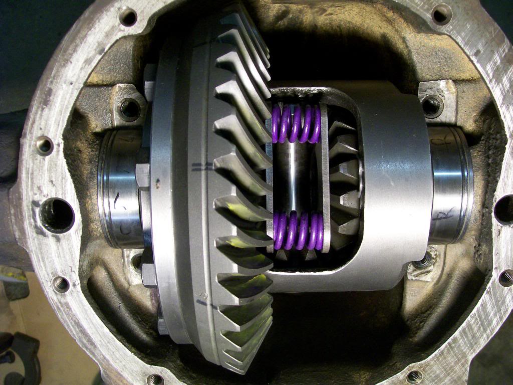
If either race is a thousands of an inch off from each other I'd be going back and forth figuring why things are changing as I'm reshimming. Lessonhere, mark everything, save a headache.
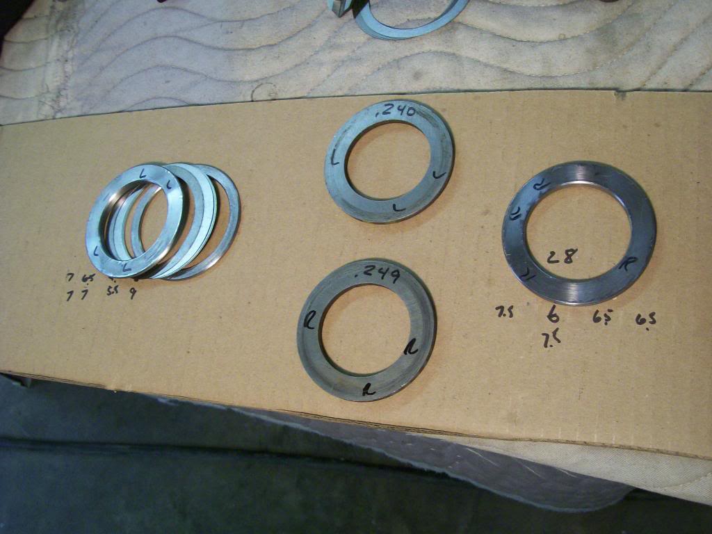
On the outsides of the carrier bearing you can see the shim backs. I like this design, shimming the carrier is easier since you don't have to remove the bearings to change the shims as I had to on the DANA 60. The DANA 60 had the shims behind the carrier bearings that are pressed onto the carrier.
Original factory shims were 1 piece, the factory has a large selection to choose from. The aftermarket has a nice pack that has two outer pieces, then you change the thin inner shims to change the thickness. Once again, mark everything from left and right.
The center shims are the factory ones, the left is the aftermarketmutipiece and the right is the multipiece assembled.
With the new carrier in place I had to remove the spider cross shaft to get the axle C clips in place. I only removed the cross shaft far enough to allow the axle to be in place to get the C clip in place. The cross shaft, even removed this far keeps the spider gears aligned in the case. Being a posi and spring pressure the probably would not have moved in the case, this idea of keeping the pin in place is just a good habit.
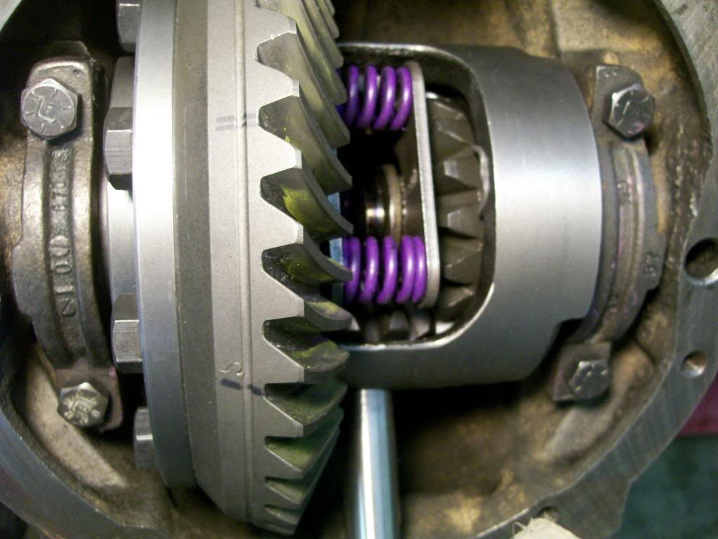
The overdrive unit gave me the option of getting away from the 3:08 gear and going to a 3:73. Now I'll have more low end torque and with the overdrive I will have better highway cruise RPMS, best of both worlds.
