You must be logged in to rate content!
16 minute(s) of a 668 minute read
10-18-2013
For the spool gun usage I'm doing here I'm doing the same as 84jeepcj7rock mentioned, I use the co2 -argon mix, it's simple just to use the tank that's on the mig welder at the time. Plus the welds are short and cosmetic.
I do have a straight argon tank attached to the tig welder, I know I use it for aluminum welding.
I'd like to experiment with different gas and welders, such as doublins mentioned a tri mix, but I'd have to commit to leasing a tank. I've looked into taking classes to learn more of the technicalities but the class schedules and my schedules never work together.
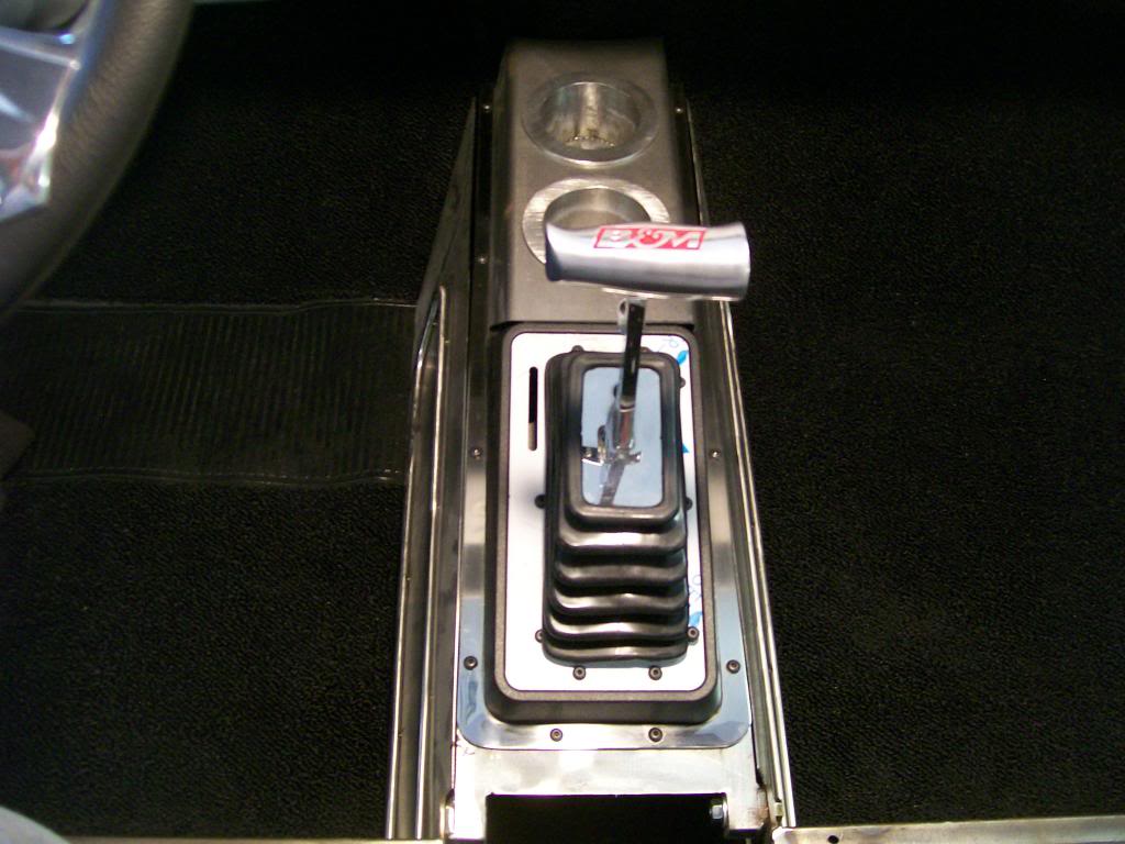
On the floor tunnel I have plenty of space so I do all these with the studs. I still have to cut the stainless trim to length. I tried to bend it to be similar to the factory shape that was built into the door panel.
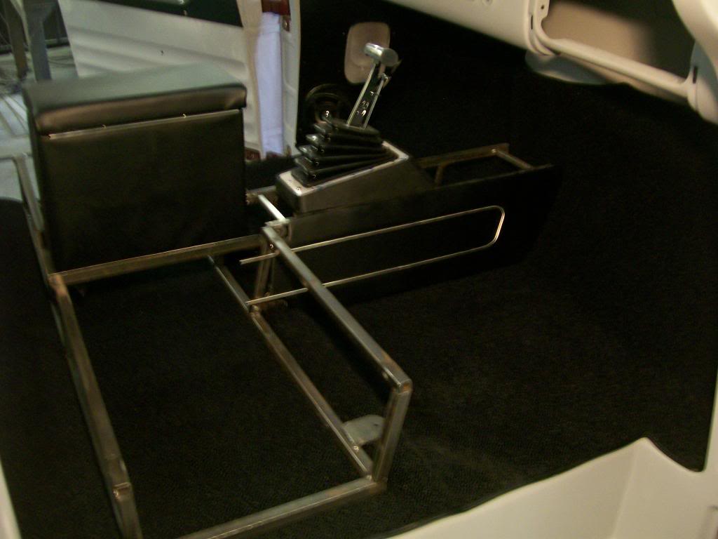
As I built the tunnel I was tying to imagine it needed something other than the side pieces. Then it hit me as I took my 65 Chevy car for a ride, it has a chrome trim that follows the whole floor counsel, that's it, that's what I need. So, next up I'm gonna create a stainless trim piece that will follow the entire upper perimeter of the tunnel.
It starts with a rough cut piece then I trim and clean it close to the size I'm looking for.
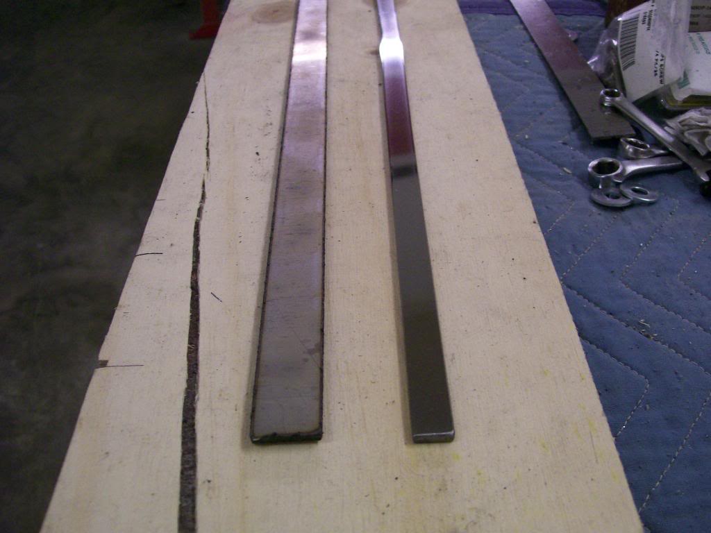
There will be no drilling and threading, but it shows what can be made from some flat straight pieces. Oh, as usual, a ton of patience and a desire to create something that I never thought of making in the past.
10-21-2013
Still working on the stainless for this truck I had to make one to follow the top of the tunnel. This is all new territory for me and I just keep jumping in head first. It's a matter of having an idea, then gathering some pieces and going at it.
I cut some 3/4" strips of 1/8" stainless. The long sides of these strips are going to vary in width since they will go around the shifter then around the cup holder zone, so the 4 1/2" grinder comes in handy again.
Three main pieces, two sides and a back. I had issues with the first couple pictures but they give the idea of what's going on.
I've got all the pieces clamped in place.
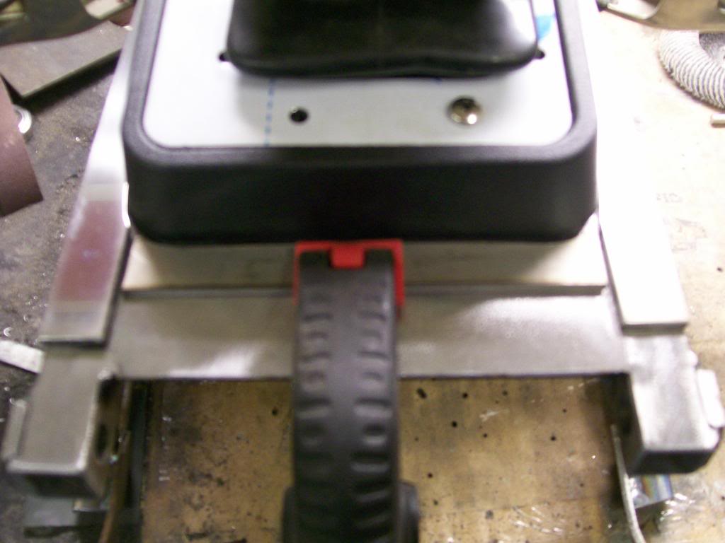
Butt ugly welds, but once again, I'm looking for adhesion and fill and these welds do just that.
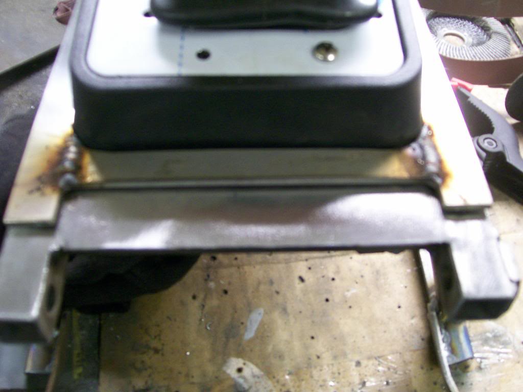
Big change here. Since the last pic I used the flap disc then used course emery cloth. I had the emery cloth wrapped around a paint stick to keep the sanding flat. Notice I left the sides a little long, I've mentioned this thought wave before.... by leaving the sides long they will absorb some of the heat from welding, this can help when welding the very edge of where the sides and the back piece meet.
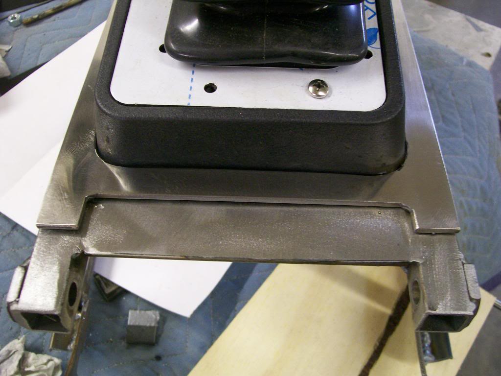
I marked how I wanted the corners to be and made a cut. Then a little clean up and I'm extremely happy. It's not polished yet, that's the easy part but what is done has once again raised the bar of my abilities.
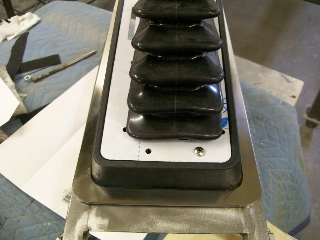
Here's closer to a final look.
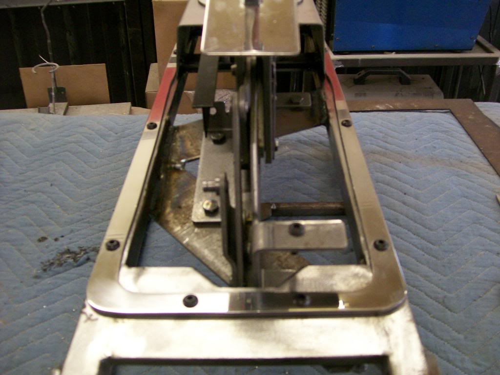
Much of the tunnel will be covered with black vinyl, this trim will be exactly what is need to break up the black.
10-22-2013
Thanks, once I decided on the black I was determined to stay away from silver paint, as you mentioned, this stainless is gonna work great with the black.
I have to admit, I'm super excited to get this all together. It'll be next spring when all the pieces finally come together. I have to hold back on any real primer or paint work due to the cold weather. The good thing is it gives me all winter to focus on getting the vinyl material glued to all the panels and spend more time getting all the odds and ends ready for assembly.
LA-Sahara, that was a huge concern when I started working all this stainless, I knew I'd need heat to shape it and the welded areas, will they clean up ok?
There is on other area that I used the heat to shape the stainless.
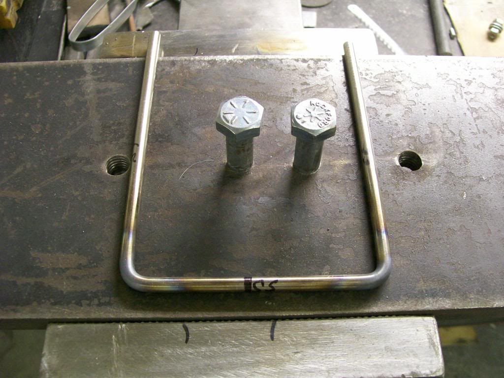
The welds and the red hot bending comes out discolored after the heat but with a little sanding and polishing the stainless is perfect after the heat. This is a huge.
The more I am working with it, just like any shop procedure, I've learned a lot about working with the stainless.
Quite alright.... warpage. If I had a water jet or perhaps a laser, yes. With the plasma cutter, the long side runs would change shape considerably, the heat and stainless really changes the stainless, especially thin and narrow cuts.
My only theory is, as opposed to aluminum which absorbs heat very quickly, and it works well with the plasma cutter. The stainless which slows the heat transfer has the area of which is being heated and concentrated begins to expand but no where else. Now on a narrow cut, say 1/2" apart like these sides are, when I cut down one side, it's changing shape, then as the next cut comes by, the metal has actually slightly relocated it self on the table so the next cut isn't dealing with the steel sitting at point zero anymore. My only choice would be to make the material larger to begin with, then grind it to fit.
With a U shape, the grinding would be near impossible.
Jeff88, you have no idea how close your question is to another situation that I ran into.
For instance.... even with the side rails being ground down with the hand grinder, the heat would cause the rails to bow. I'm talking like a 1/4" variation from one end to the other. I was about to scrap the idea, I was pissed.
No matter what I did to shape the rail to match the shifter and the cup holder, I just could get it. I ground where I marked it, then I would check the fit to have it be off some where else.
It wasn't changing from top to bottom, it was changing from side to side, as a snake moves.
It was going to be scrap anyway so I tried to hit the side with a hammer softly, no change. Then I held it at both ends and hit it over a wood 2x4, it got straighter. Long story, but by the end, I'd grind, it would warp sideways, I would reshape it on the 2x4, and I learned a new tactic.
I conquered, and I got my trim.
10-26-2013
Ha, ha, the 2x4, my first hit was slightly angered, I hated to be beat and not being able to make the trim. Something about the make up of the stainless that allows it to be shaped by tapping it sideways.
I'm gonna move to "now" time. I just finished making something I have struggled with trying to imagine how to make something.
With this truck, I want to do burn outs. I however don't want to snap the throttle to break the tires lose, I want to lock the front tires with a line lock, then slowly apply the gas and begin a burn out.
What I imagine being a problem is the leaf springs are very long, I fear a problem.... "wheel hop".
I know there many different traction bars available or in my case, build-able. I do not want to have the feature of weight transfer as much as I want to control wheel hop. I'm gonna go with a style called "slapper bars".
This is gonna be a fun build, fabrication. But first it's homework time, anybody want to explain the function of the slapper bar?
Here's the fun part, once you learn how they work, picture this.... my axle is below the spring, the axle leaf spring plate is above the leaf spring assembly.
10-27-2013
Wow, a great flashback and thanks for putting a real life situation into your reply.
I also remember the "too wide of tire" and the rubbing of the wheel well when going over bridges and anything that caused the suspension to compress.
Mine was a 72 Nova, I sure learned a lot from that car. It had an automatic transmission, then I converted it over to a 4 speed, that's when the wheel hop problem began then came the traction bars/slapper bars.
Let's first recognize the common cause of wheel hop, a thing called spring wrap. I'm gonna show a picture of the leaf spring of my 57, this has a very long spring assembly, in my mind, the perfect candidate for wheel hop.
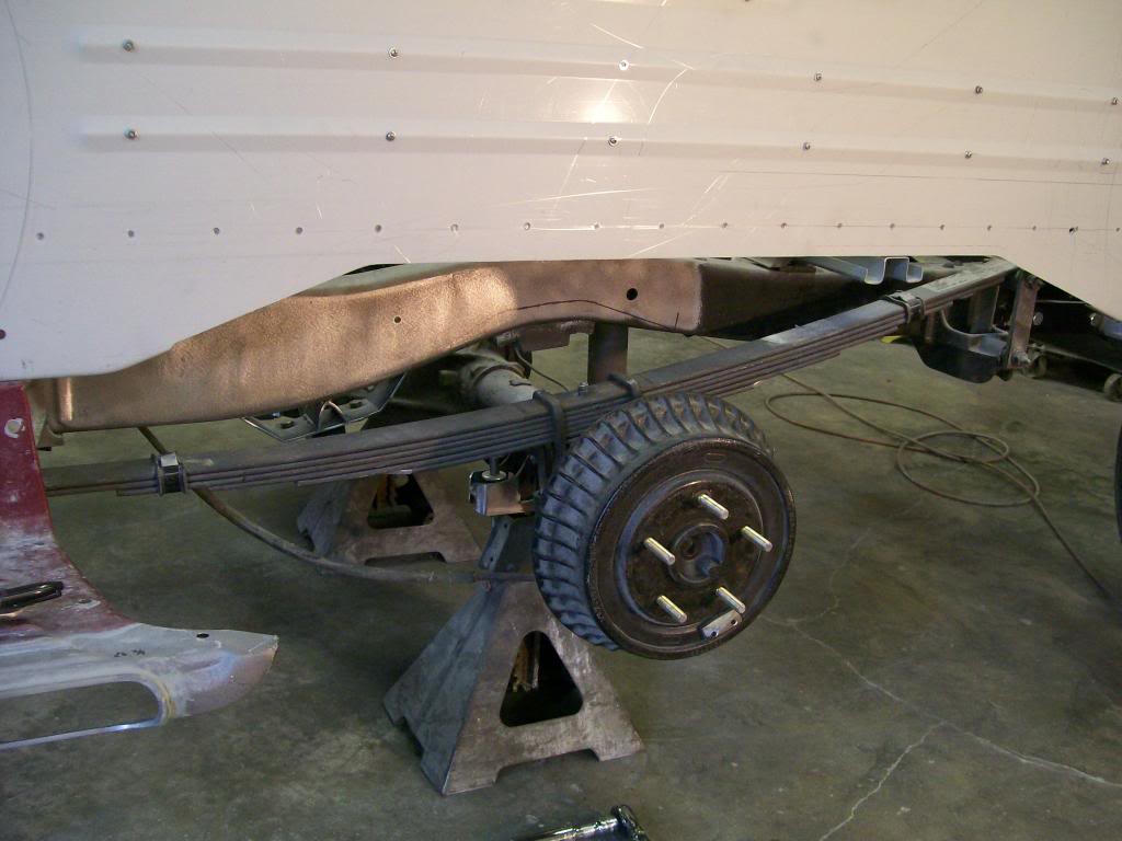
Ok, imagination time... inside the differential is the ring and pinion. When power is applied to the pinion it's natural action is to turn the ring gear. If the ring gear has no resistance the two will turn and the axle housing simply has spinning gears within. Now we apply power to the pinion and we have a resistance such as moving a car. With the ring gear resisting to move the pinion will try to climb the teeth of the ring gear and since the pinion is contained in the front of the differential and the differential is a part of the whole axle housing the whole assembly is being twisted nose up.
Here's the problem... the housing is attached to the leaf spring assembly, an assembly that's original function is to flex and return to it's original shape. This is great as a bump absorbing suspension, it is the twisting axle situation that is the problem. The leaf spring assembly also flexes to absorb the axle twist, something that in most situations is perfectly fine, yet in a burn out situation, this is the beginning of wheel hop.
Absorbing the initial twist of the axle housing is fine to a certain extent, where the problem begins is as I mentioned, the leaf spring assembly absorbs, then is wants to return to it's original shape. Once the spring becomes warped from the twist of the axle and if the twist has put a lot of force/return energy into the leaf spring assembly it will snap back trying to return to it's original shape. Now the wheel hop starts, the springs absorb, then snap back, then absorb, then snap back. This fast repetitive action causes the rear wheels to bounce up and down off the pavement which is our wheel hop.
If this continues, most any thing in the drive train is taking a beating and sooner or later something has to give/break.
There are choices to solve this problem, slapper, ladder and 4 link. All three control wheel hop, the slapper, controls wheel hop, they are not designed to cause weight transfer, but the better traction with slapper bars results in some weight transfer. Ladder bars control wheel hop and are a more mechanical way of controlling wheel hop, they do add to weight transfer with their design, a good in between design. The ultimate is the four link, the design cancels wheel hop and helps weight transfer happen, adjust ability, is a huge benefit of a 4 link.
The slapper bar design is usually bolted directly to the bottom of the spring perch on the rear axle. As the axle tries to twist under load, the slapper bar being bolted the the perch also rotates with the perch. The bar with a rubber snubber or bump stop reaches forward to the front of the leaf spring where it is mounted to the frame. As soon as the axle starts to twist, the rubber bumper touches the spring mount. Once the bar makes contact and since it is connected to the axle, the axle can not twist, no twist means no leaf springs being warped out of shape, no leaf spring being warped out of shape means there is no stored up energy to snap the spring back to it's original shape, no snap back means no wheel hop.
Ok, that's a short theory behind traction bars/control. My design will not be the normal way of having slapper bars, my spring perch on this truck is above the axle and since I have to make contact with the bottom of the leaf spring I have an over-under issue. Go ahead and Google slapper bar images and the one constant is having a bar hanging down under the axle and leaf springs, I do not want this look either, it just does't match the look of the truck.
I'm always stressing the knowledge of the theory behind the parts we use, this is a fine example of using the theory with a different design to get the same result.
We'll start the build next...
10-28-2013
Definitely a big thanks for checking in. You've noticed the different places around the world checking in, sometimes the locations catch my eye and I have no idea where some are located on this planet earth, very cool this internet thing.
I'm sure I don't have to mention my......ummm,well.....joy, I have with my welding equipment. It has broken down so many walls that otherwise would have stopped projects before they got started. I hope that if the welder shows up for Christmas, through this thread you'll be able to quickly advance what you can do with it.
Here is what I have to start with, it is a spring over axle situation. The spring is a direct replacement only altered slightly to drop the rear of the vehicle a couple inches. The u bolts are the original design and the cast iron clamp/shock mount on the bottom are also original. I don't want to weld anything to the bottom on the axle, no particular reason, I just don't want to hang anything below it so the original stuff stays as is.
What has changed is the 3/4" chunk of steel that the u bolts go up and over. Someone changed it many many years ago. I feel it's a hazard, the only thing keeping the u bolts in place other than being tight is a small weld bead at each end, yikes, flimsy. This will be changed. Oh, I'm also disappointed with the perch that is welded to the axle.
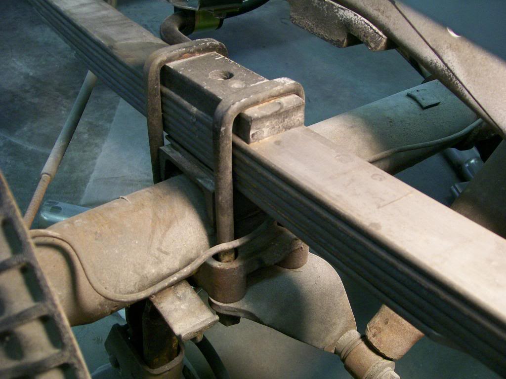
Here is one main piece that will replace the 3/4" chunk of steel.
I've shown this process of bending the 1/4" plate many pages ago. This is going to be a top plate like I haven't seen before.
Once I bent the sides downward I drilled 4 holes, and one in the center, 5 holes.
I'm stopping here for tonight, use you imagination and try to see where I'm heading from here.
Side note..... The final design will still look the same, I will however change the bend slightly before I'm finished. Why do I bring this up?? Because I don't want anybody to think I imagine, cut, and build, it doesn't work that way. I have tolerances I want to keep, I alter along the way for a better design, I'm constantly concerned about size and dimensions ect. Often times if any of these categories are not met I will toss aside, modify or start new. It's all a learning process.
