You must be logged in to rate content!
9 minute(s) of a 668 minute read
1-23-2013
I don't have a stock radio, but the nice thing about working on this Chevy is the abundant amount of aftermarket parts available.
All that is required now is have the cash and order a radio that fits the opening in the dash. I don't remember the name of the company but the radio fits perfectly.
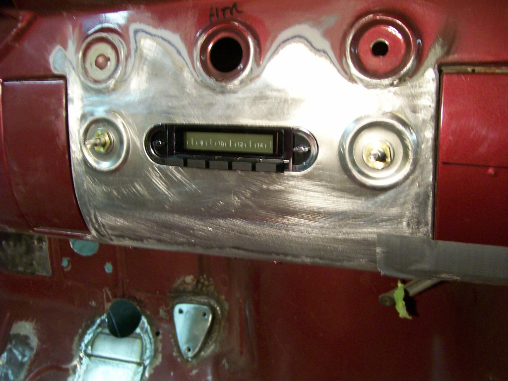
Sorry for the blurry picture. I've taken over 2000 pictures and it might be time for a new camera.
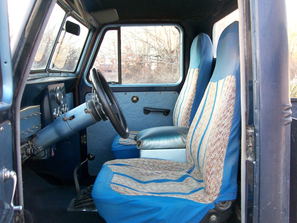
I had the Willys parked by the shop the other day and I remembered I promised an interior shot so I grabbed the camera. After working on the Chevy for so long I kinda forgot how small this Willys cab space is.
This is pretty well the way it's been for 27 years now.
1-25-2013
I got the go-ahead on ordering parts for the Dodge 360, so it'll still be a while til we get further on it.
The turbo 350 transmission and it's owner showed up the other night so we disassembled it right away to see what parts it's gonna need to get it back in good working order. Quite frankly I'm surprised this transmission moved the truck at all. Internally it was missing a couple pieces, the passing gear cable wasn't hooked up right and the transmission showed signs of overheating in the past.
I've got some pictures of the main parts. The only pic I have at the moment is the mass of pieces after the tear down.
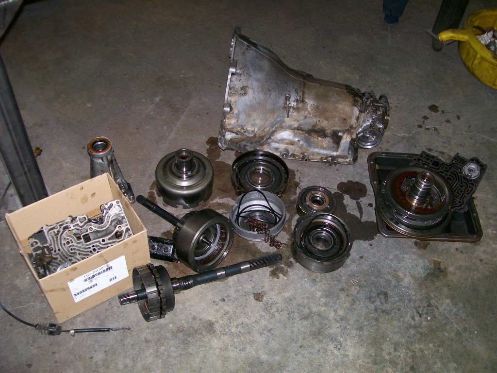
In the next posts I'll touch on valve body, front pump and a clutch pack. My main goal will be as I did with the Dana 60 rebuild, simply introduce and take some of the mystery out of the parts.
1-26-2013
With the transmission upside down, the pan is off and the oil filter is also removed. The gray cast iron unit here is the valve body.
Basically the brains and fluid distributor of the transmission.
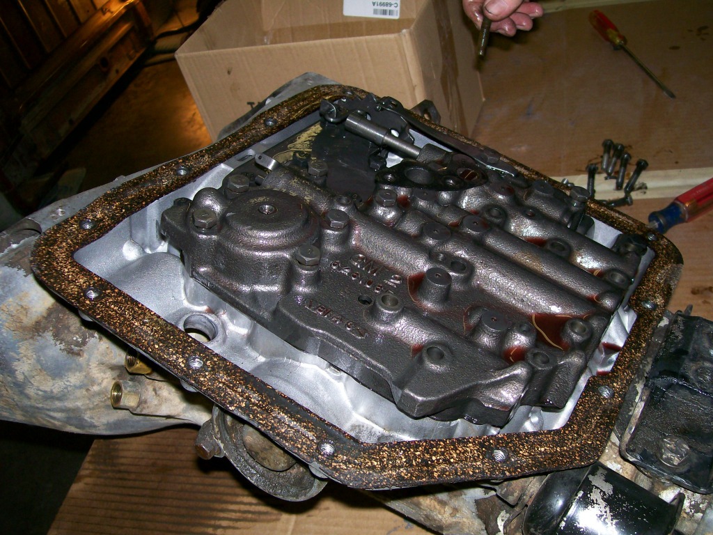
Once all the bolts are removed the valve body separates from the transmission case. This picture has two purposes.... 1) just to see the underside of the valve body. 2) look closely at the valve body you'll see where there is pin sticking up above the surface of the valve body.
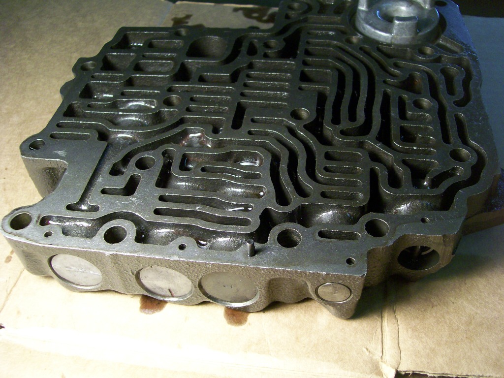
I'm sure most everybody has heard of a shift kit. One of the main changes to make with a shift kit installation is to remove the aluminum piston that is being held inplace with this pin that is sticking up. Once the piston is removed, the original spring within will be replaced with a new spring provided in the shift kit.
The next pics will show this piston out so you'll see how the pin held it in place.
1-28-2013
Still working on the valve body pictures. The pin that was raised in the last picture has now been totally removed. Once removed the piston can be removed.
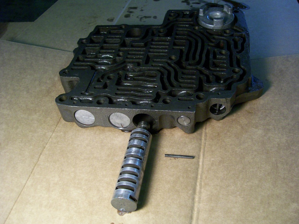
Looking at the piston you can see where there is a slot where the pin fitted into. The only thing that holds the pin in place it the tension on the spring pushing the piston against it. When it's in bolted in place the pinhole is upwards and since the pinhole is not drilled all the way through, the pin stays in place.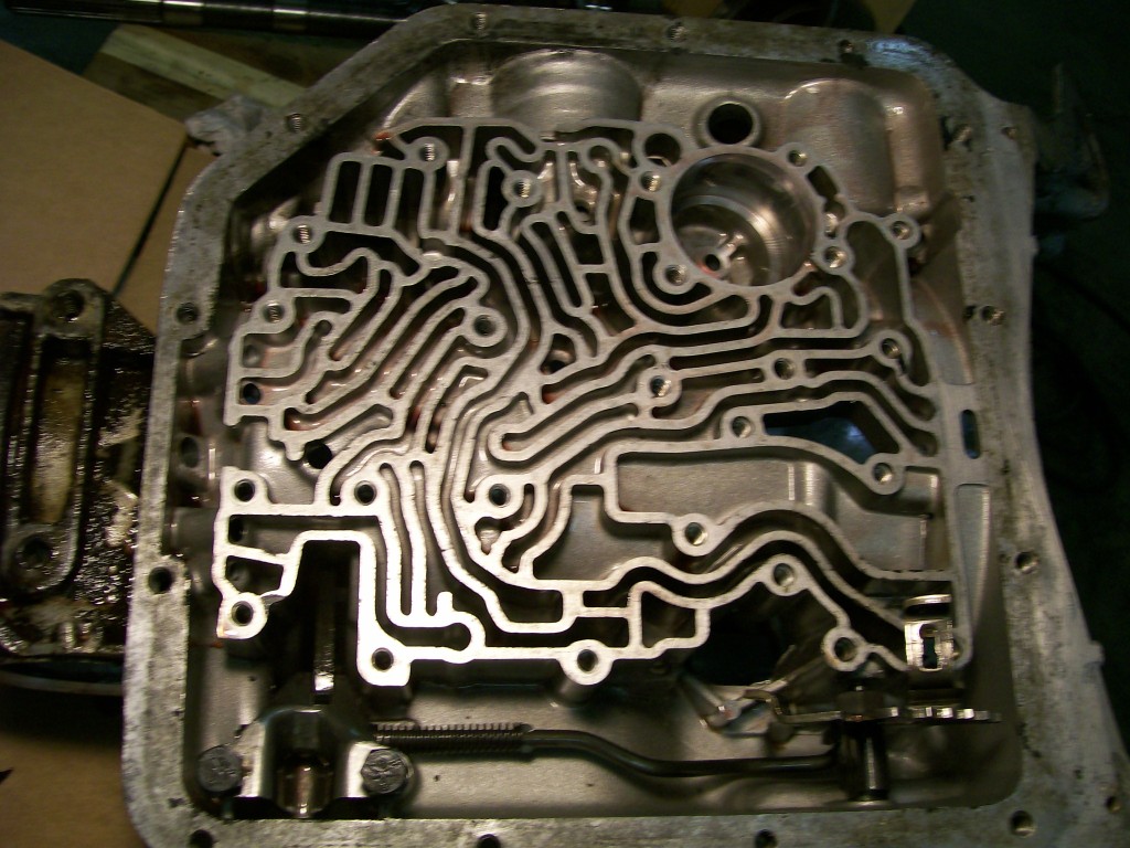
A look at the transmission case with the valve body removed. Looking at the casting there are 4 round pockets that allows small round check balls to fit into. I'd show the check balls but......since this transmission is missing them, I can't show them.

I believe these check balls cover fluid passages and block fluid back flow. This is the first transmission that I've torn apart and found every friction/fiber material to scortched/overheated. I suspect missing these check balls allowed fluid to go where it wasn't supposed to. The low pressure going to different clutch packs at the same would cause excessive heat do to clutch slippage. Similar to driving a manual transmission vehicle with your foot resting on the clutch pedal causing the clutch to slip the whole time your driving.
1-29-2013
Moving to the front of the transmission, the front pump is the first item to be removed.
The front pump has bolts to be removed around the outer parimeter. The pump is not pressed into place but it has a rubber o-ring that fits around the pump to seal it against the case. This rubber o-ring fit keeps the pump in place even after removing the bolts.
Look closely at the bolt holes after removing them, in two of them you'll find 3/8" threads. These threaded holes allow you to thread a slide hammer into and pull the front pump from the case. It would be proper to use two slide hammers at the same time, but I am careful and one has worked for me.

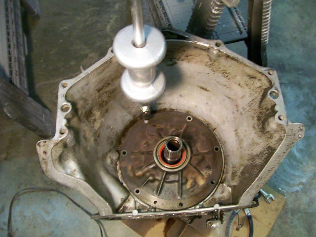
I've already gutted the transmission, usually you'd have the input shaft coming through the center of the pump.
Once the pump is out we'll take a look at the backside of it.
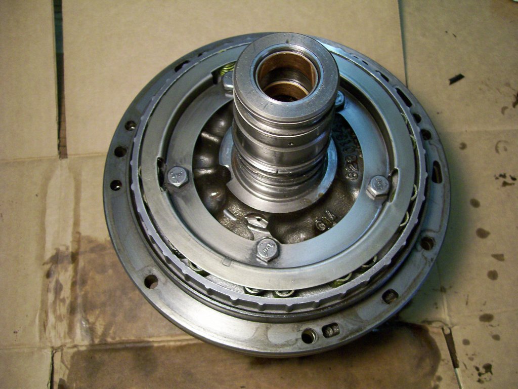
The pump is two halves bolted together. It also is part of a clutch pack. The 5 bolts not only hold the pump together, they also hold a large aluminum piston in place. Under the steel ring there are a set of springs.
Springs can be scary at times, questions arise such as.... what's behind them and once apart, how do I get them compressed and back together again?
Good news, the bolts are long enough to recapture the steel ring and compress the springs when reassembling.
1-30-2013
After removing the bolts that hold the pump together, we have multiple pieces to deal with.
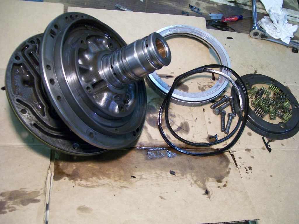
You can see where the cast iron pump has split in half. Along with the pump being in half we have the bolts, the steel ring the aluminum piston a couple of large rubber seals and a set of springs.
Focusing on the piston, seals and springs, basically there will be fluid pressure coming in behind the aluminum piston. The rubbers seals will hold the fluid and the pressure will compress the springs. There is a set of clutches that will be compressed as this all happens.
Later I'll have a clutch pack picture that'll show a better breakdown of how the piston works with the clutch discs.
For now we're gonna take alook inside the pump itself.
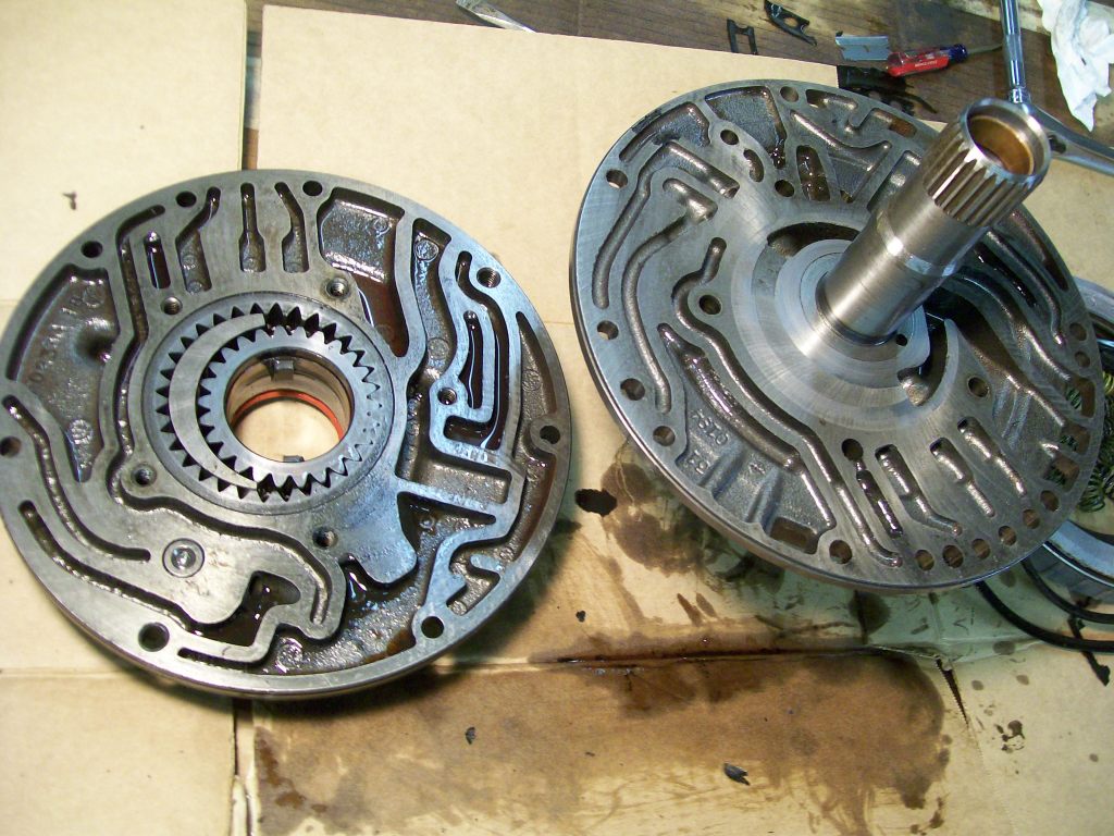
Mainly a set of gears working in a way to build fluid pressure. Since the transmission is hydraulic, fluid pressure is the key to everything.
Looking at the smaller gear you can see two inner fingers, these are the two fingers that match up to the torque converter where you have the two notches on the part that fits into the pump when installing the torque converter.
2-1-2013
Thanks for checking in exige05 , here comes the next couple of pictures.
Moving deeper into the transmission we get to a forward/direct clutch. The clutch pack has both the hydraulic piston and the discs contained in one unit.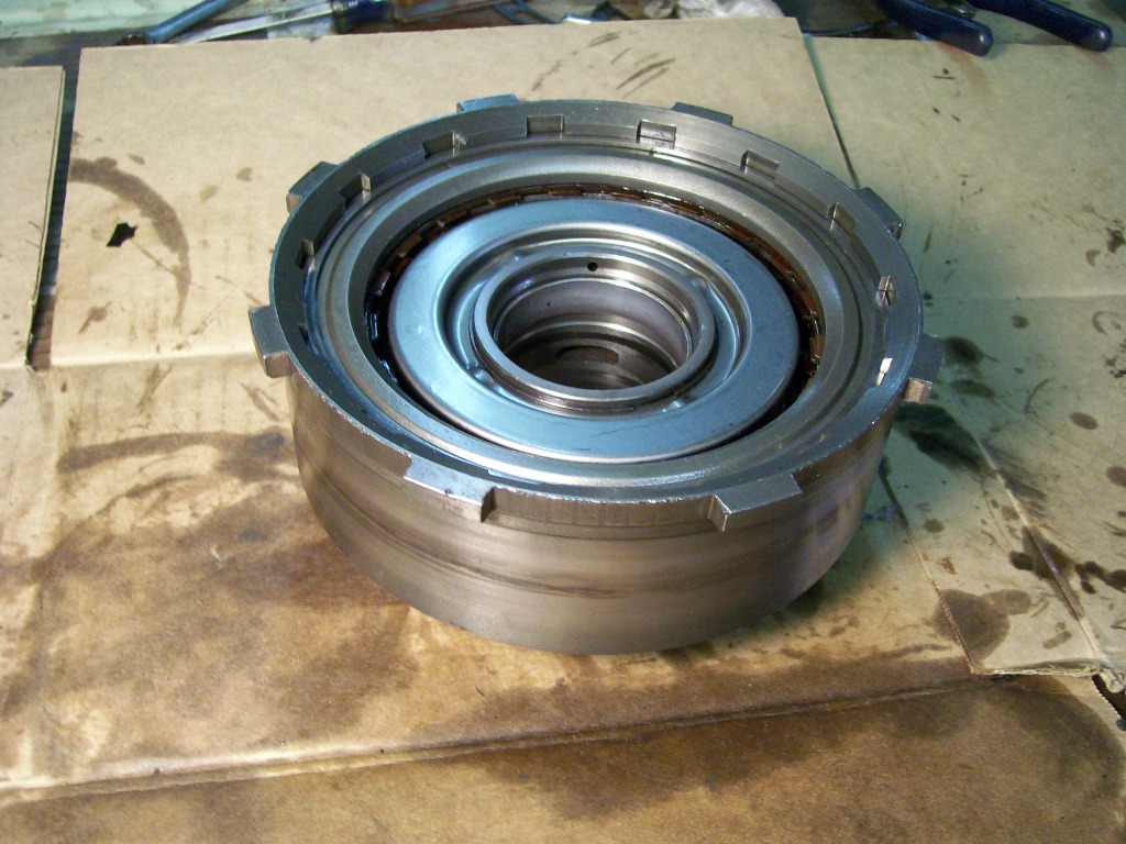
The first thing to do is remove the steel and fricton discs before we can remove the piston.
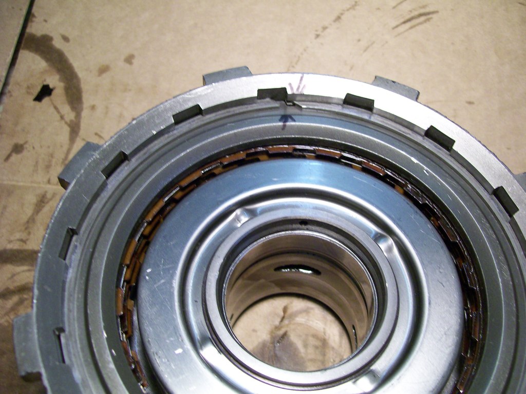
The discs are easy to remove, simply get a screwdriver in behind the outer snap ring and pry it inward. Remove the ring and flip over the pack and the discs all fall out.