You must be logged in to rate content!
15 minute(s) of a 668 minute read
10-21-2012
Alrighty, let's move onto the next tool.
Cylinder hone... if you are already going to bore the cylinders, this tool is not needed. Once you send the block off to the machine shop, they will go way beyond what a cylinder hone will do to the cylinders. Although, once they bore the cylinder they might finish the process by using a hone to get the desired finish.
Now for the engine rebuild that the block is not going to be bored, the cylinders need to be honed.
There is a term called "seat the rings". The idea is that the cylinders now have a polished surface, the old rings have left a glazed finish on the cylinder walls. This glazing, if left alone and the new rings are installed, the new rings will not seat themselves to the cylinder walls. The result will be lost compression and oil burning.
A look at a cylinder hone.
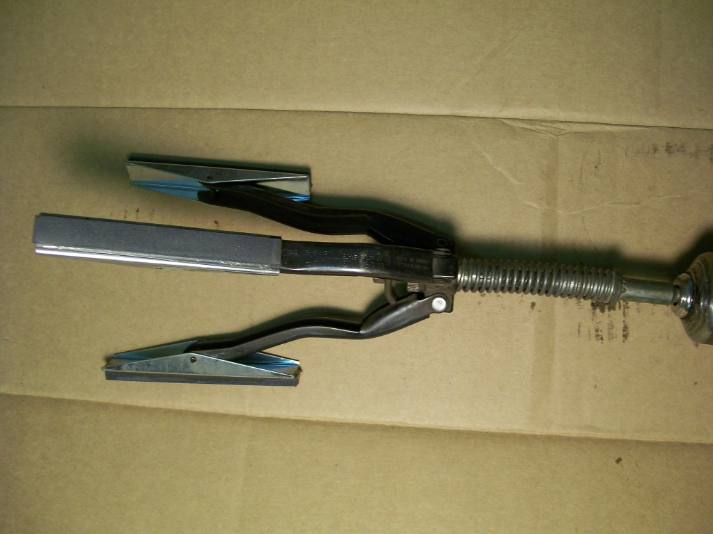
There are different designs of hones, this is just the one I used for years. They basically have the same purpose. The stones on the outside of the three spring loaded arms are will be spun by a drill inside the cylinder. The goal is to remove the glazing left over from the old rings and to leave what is called a crosshatch finish.
A look see when the hone is placed in the cylinder.
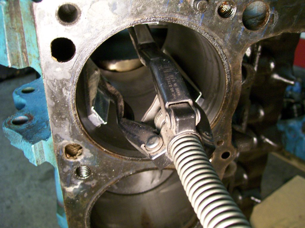
The idea is to spin this hone, while spinning inside the cylinder it is removing the old glazing and we're gonna have a clean cut cast iron finish again.
The crosshatch finish is created by the hone not only spinning in a circle, but while spinning it we have to manuallly raise and lower the hone while it is spinning. Now when finished there is a surface that you can see the cut marks criss crossing each other.
While honing, you have to use a lubrcant. This will be operators choice. I've seen anything from oil to transmission fluid, to WD40 used. Also while honing, the stones will get clogged quickly, I usually have a can of brake cleaner to clean the stones, and the cylinder, then relubricate and hone somemore.
Hone the least as possible, as we hone we will remove material from the inside of the cylinder wall. This will create a larger ring end gap and piston to cylinder wall clearance.
10-22-2012
Yes, practice and patience is true in every aspect of rebuilding most anything.
This is where I restate my intention of most of this thread......
Going back to rebuilding the Dana 60, you'll notice I never gave torque specs. I never gave backlash settings, ect.... My goal is mearly to uncover and expose what's hidden beyond the pan. I've wandered many a forum about rebuilding engines, wow, there are a ton of opinions on just about every aspect of the rebuild.
I know if I say I like a high volume oil pump, the next person would say it's not necessary, then the next would say you need a larger oil pan. If I say cast pistons would be fine, the next would say they wouldn't run anything other than forged pistons. If I say I like moly rings, the next would say cast rings are better. We've all had different experiences with our builds and I'm not here to influence anyone to use certain products, I'm only concerned on showing where the product goes and it's pupose.
I'm not even interested in getting into much of the clearances and torque specs, these are in the shop manuals. My only goal is to give a visual along with verbal description to items and conversations that many have heard of but never had the opportunity to put all the pieces together.
I see the mention of posting some youtube videos, this is a great idea. I remember the one that was posted about spider gears, it was fantastic.
I also understand the idea of screwing something up, believe me, I've tested the waters. This is definetly a personal choice when it comes to rebuilding, or building anything. The effort can be costly or very rewarding. I remember my first engine rebuild, a 1969 Olds 350. I was 16 and nervous as can be. I'm just saying, in order to advance, we have to step out of our comfort zone once in a while.
In the mean time, I'll at least introduce more of the engine and hopefully others will help with the videos they are familiar with. Truthfully, I know I'll pick up a few pointers in the videos also.
10-23-2012
axxxgijoexxxa and herklord, Thanks the both of ya for checking in.
You both had one liners, coming from two different perspectives. I'm glad to be able to get the gears of thought going for you both.
On this engine project there has been a change. The original engine we started with was a 318 as we've seen, it's going to need some work. The bock needs to be bored, the crank either needs to be turned or replaced. Along with the boring, new pistons need to be purchased.
All in all, it's a 318, we could put a bunch of money into it but this is how I look at it. Taking an average V8 engine, well built for street usage, good flowing heads, approx. 10:1 compression, we can figure around 1 horsepower to 1 cubic inch. So... 318 cubic inch, 318 horsepower.
My issue is, all this money in a 318 or all this money in a 360. If we build the 360 and using the 1 to 1 ratio, well..... I figure 350 to 360 horsepower. That's approx 40ish horsepower gain, that's a good kick in the seat.
The owner did a search and found a 360. It has been rebuilt in the past, but there are some promising parts. The heads will certainly flow much better than the 318, I will post pics later of the differences. The crankshaft is still the original size and needs nothing more than a polishing on the journals. The cylinders are .060 oversize, this is the last time it can be bored, but the cylinders should clean up ok. By my figures this should now be approx 370 cubic inches.
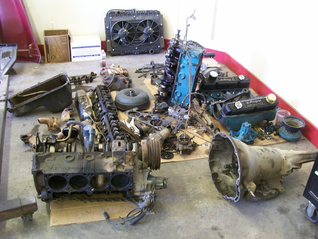
Two engines apart.
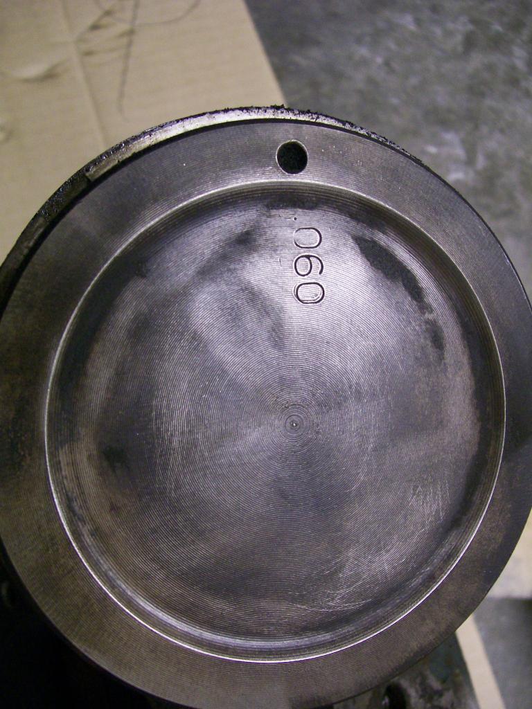
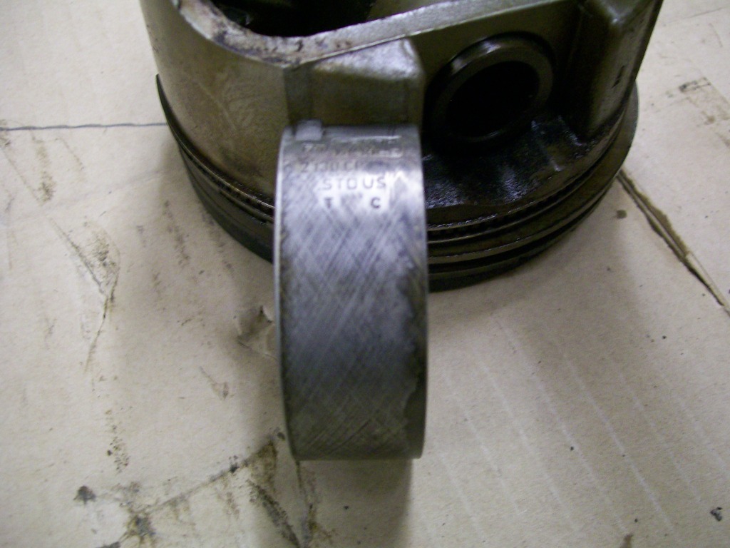
Aftermarket pistons will almost always have the overboresize stamped on the top. In this case the .060 is clearly stamped.
Next is the good news, I could only hope the crank hasn't been undercut too much. Once we removed the rod caps, we slipped the bearings out to look at the bottom side of the bearing. Once again, if the crank had been turned to a smaller size, say .010 or beyond, the rod bearing will have a stamping showing the size.
Looking closely at the next picture, it is the underside of the rod bearing. You can see were it reads STD. This STD means it is a standard size. This is great, I perfer an original size crankshaft.
Never assume without measuring the bore and the crank journals before ordering parts though, just to be sure.
Ok Jeff88, I'm gonna beat you to this one............
STD does not mean Sexually transmitted desease.
10-24-2012
I've got some pictures of the heads, more specifically, the ports.
There's alot of chioces while building an engine. I kinda devide the engine into two parts, one, the part that developes the power, and two, the part that supports the power.
The block and the rotating assembly basically is the supporting part. We've looked at some of those parts so far.
The part that makes the power is most everything having to do with the air flow starting with the air filter to the tailpipes. Tonight the focus is the intake manifold to the heads.
Port matching I believe is the term. Once done, the intake manifold gasket is going to be used to mark a pattern to follow with a small grinding tool. This will give us the most flow from the intake manifold. In the next picture, by laying the intake gasket inplace, you can see where the intake manifold can be cleaned up a bit to use the space provided by the intake gasket.
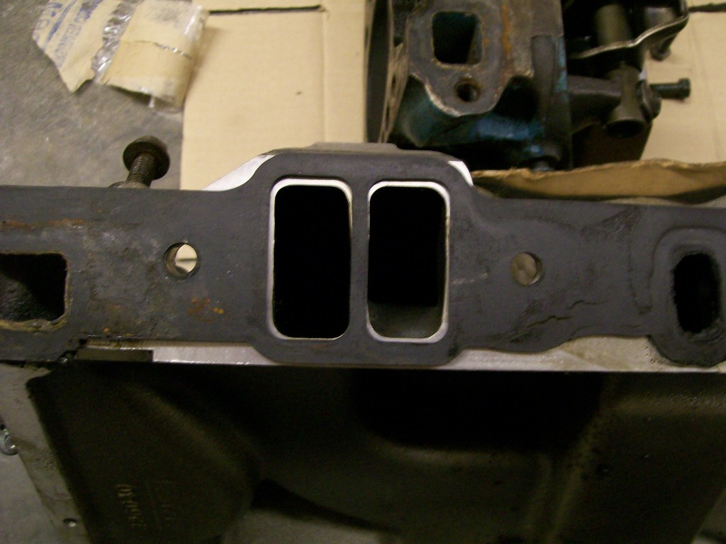
The intake should go pretty easy. Now looking at the head from the 318 engine. Once we layed the gasket inplace we were like, WOW, we can certainly help this thing breath better. Here's the head with the gasket in place. Check out the amount of port that is blocked with the cast iron.
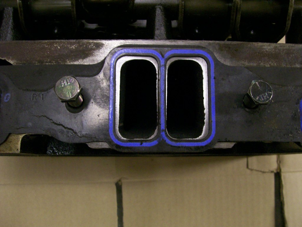
Image this, the width that can be opened up with each port is about 1/8". Since each port is around 1" wide and 8 ports, that's the size of one whole port that we could gain by opening them.
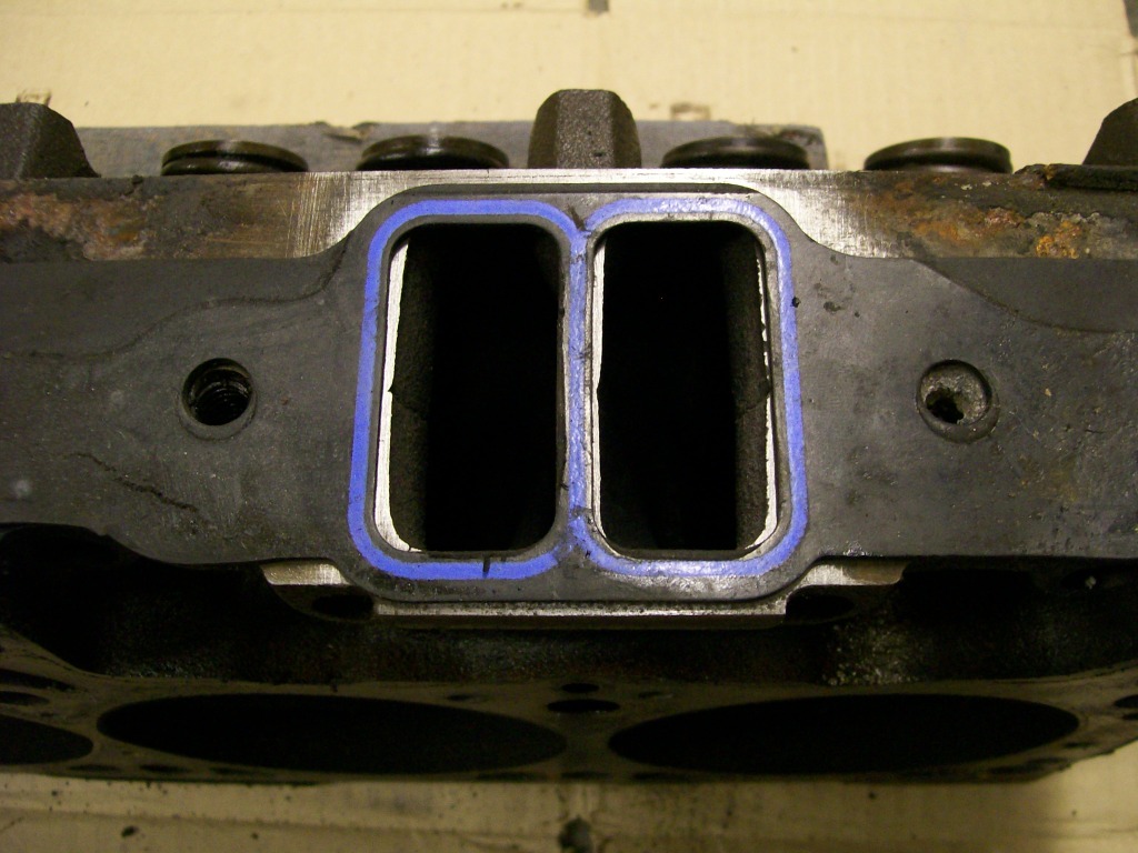
I'm not a big Mopar guy so I wasn't expecting the 360 heads to be any different regarding the size of the ports. Once we took the heads off and layed the intake gasket we been using on the ports it was a great feeling. The ports were larger than the aftermarket intake manifold, and matched the gasket much closer. We'll still do some on these ports and these will match great when done.
The engine can only produce power by the amount of air that it can pass through it. The owner was happy with the 318 power as it was with the restictions in the old heads. Now with a better flow, much larger engine, I know he's getting excited to get this running. Hmmmm, now he has to get past the tough part. $$$$$.
10-28-2012
Still looking at the cylinder heads and putting the air flow at the top of the priority list for developing power, I'm heading to the underside of the heads.
In the next picture I've placed the 318 head up against the 360 head. The 318 on the left and the 360 on the right. The difference doesn't stand out, especially when there is a slight casting difference between the intake and exhaust valves in the two different heads.
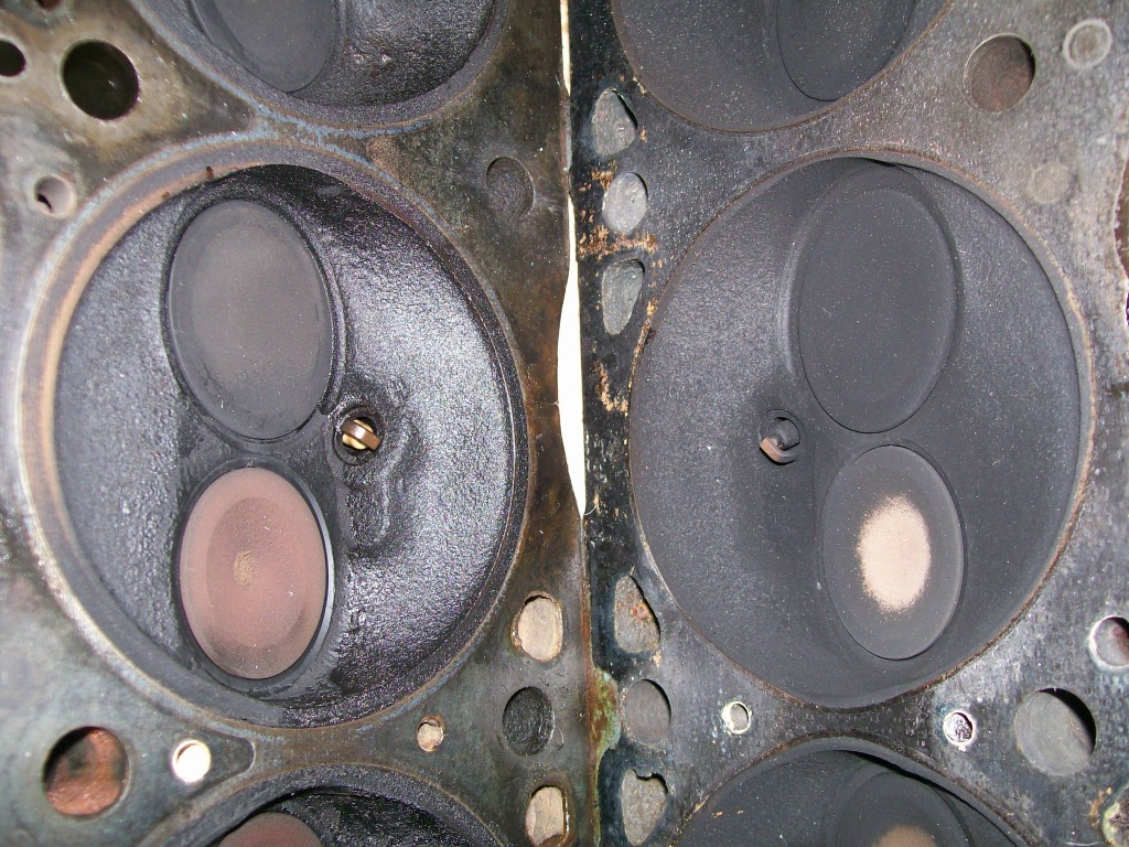
The focus is in the diameter of the face of the valves. Obviously the larger the diameter of the face of the valve, the more air that can flow past the valve when it opens.
Heads have different reference terms to describe the head casting. For instance, Chevy small block had a head called "Double hump" heads. This was a symbol in the casting that was a way to tell if it was a performance head or just a normal head. I've heard terms used to identify these Chrysler heads, but I'm not familiar with the terms. My only concern now is to work with these heads and try to get what I can out of them.
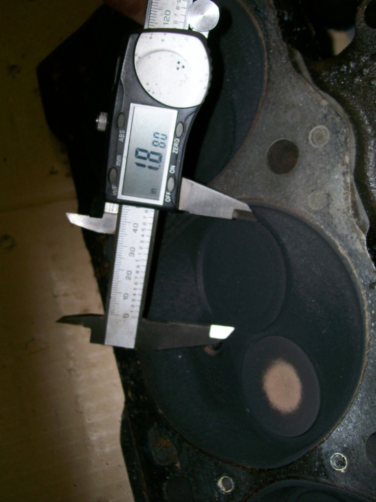
Another way to identify heads is the term "2.02" or 1.94 ect. This is an identification that usually is identified by measuring the valve face diameter.
In the case of the 360 heads, by using the digital caliper I can take a quick measurement of the valve face of the intake valve. The 318 intake valve measured somewhere around 1.74, this 360 valve measured at 1.88, this is a good thing.
Along with the intake valve being larger than the 318 intake valve allowing more air flow into the cylinder, the exhaust valve is also larger allowing the burned gasses exit the cylinder quicker.
The original 318 had a stock factory cam, the 360, when done will have an aftermarket cam. Now along with the larger valve diameter, the new cam will open the valves at different times in reference to the piston stroke. Not only will the larger valves allow more flow, the valves will open further and for longer duration of time.
11-3-2012
Update....
I have to get more pictures of the engine progress. I've got the owner doing some port work at home. New pistons should be here next week. We did a check of the connecting rod bearings to the crankshaft journal clearances with the plastiguage with very good results. New ARP main cap bolts and rod bolts are ready. I'll have pics up soon to give a better explanation with pictures.
On the other side of the shop I still have the 1957 Chevy truck. I know the weather is going to turn cold soon and I don't like to run the heater while spraying primers and paints. I took the front fenders, doors and rear fenders and decided to get them all in primer before winter.
I mentioned I was going to give epoxy primer a try. I ordered Eastwood products epoxy primer. Very pleased with the product. Simple 1 to 1 ratio to mix, sprayed and layed down smooth. I sprayed the bottom side of the fenders first, then waited a couple days then sprayed the outside.
After spraying the outside I waited a little over a day, then I lightly dry sanded one fender to check it's curing time. By lightly sanding dry, I can watch for the primer to leave small clumps on the paper, this is the sanding marks you see on the one fender.
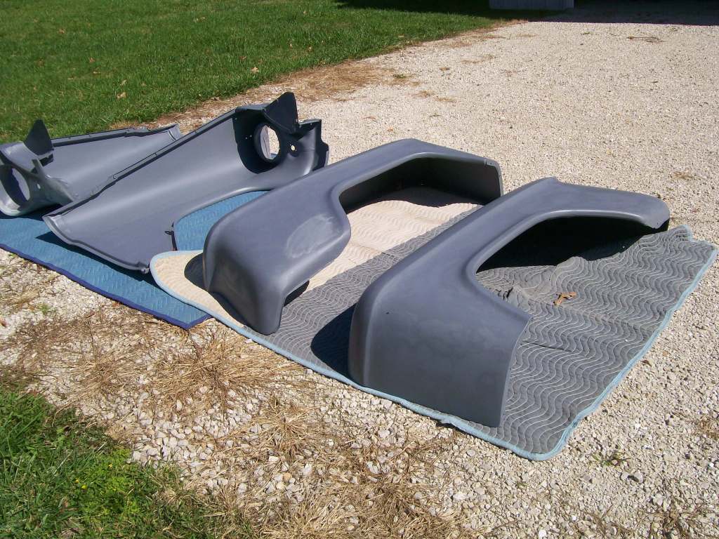
The primer is said to adhere well to bare metal as well as any body filler. You can see where the discoloration on the fenders shows where the body filler is. The filler will absorb the moisture content in the primer more than the bare metal, I believe this is the cause of the color change.
I set the fenders out in the sunlight for a couple hours, by the end of the day the primer was ready for wet sanding.
11-4-2012
I believe you are correct. I was doing some checking and it looks like the 318 heads can also be converted to 2.02 also.
We're working on a pretty tight budget on this project. He was happy with the power of the old 318, just concerned about the low oil pressure.
Finding a .060 over 360 converts to a 371 cubic inch engine now. It came out of a running vehicle, which is a plus, we know it was a runner before he bought it. Everything looks good, even the pistons, but they were a dish top, lowering the compression ratio down to the 8's. With the new flat top pistons we should be back up around 9.5 compression ratio.
This is his first real engine rebuild so I'm enjoying sitting back and letting him do most of the work and I mainly supervise.
Both of us are looking forward to seeing the difference once this is up and running again.
