You must be logged in to rate content!
12 minute(s) of a 668 minute read
9-18-2012
South Africa, are you kidding me. It's posts like this that nearly bring a tear to my eye.
What I mean is, we all know this internet is world wide, it's not till I get replies from around the world that I recognize the world wide coverage.
As Gojeep and I mentioned before, I have many friends who haven't taken the time to check out this thread, yet here you are, half way around the world getting a view of what's happening in my shop.
I have to mention, back in 1979 I spent 4 weeks in Africa. My dad had a work related visit and the family went with. We were in the Kenya area, many good memories.
Having a Jeep and a Chevy makes me suprised to hear the american vehicular influence that is over seas. The Jeep is looking good, yet over here that would be a Mail Jeep with the steering on the wrong side. lol, just kidding.
I remember my dad driving in africa and his natural instinct was to drive on the wrong side of the road, took him a while to get the hang of it.
On the interior I am going to an upgraded guage cluster from Brothers truck parts, should be at my door step tomorrow.
Probably just a carpet kit, a tilt wheel but I'm gonna keep the key in the dash. Not much more, my intent is just to have a fairly stock truck with an attitude under the hood.
Thanks for checking in.
Thanks for the comments. Yes, as many have read the pages, there have been many comments stating how they appreciated the effort of building this thread, and No, it never gets tiring reading the replies, they are what keeps this thread going.

I finally got into my e-mail and found the message that was sent out from the Jeep forum administration. Now I see what happened. Thanks Jeep forum for the nice write up.
Hopefully anyone who has read the 70 some pages knows that I too have learned from this thread. Over the last year there has been some great advise and input from others, thanks to you guys too.
I'm saying this for I don't know everything, but for everything I know, I try to picture and explain it the best I can as I keep working in the shop.
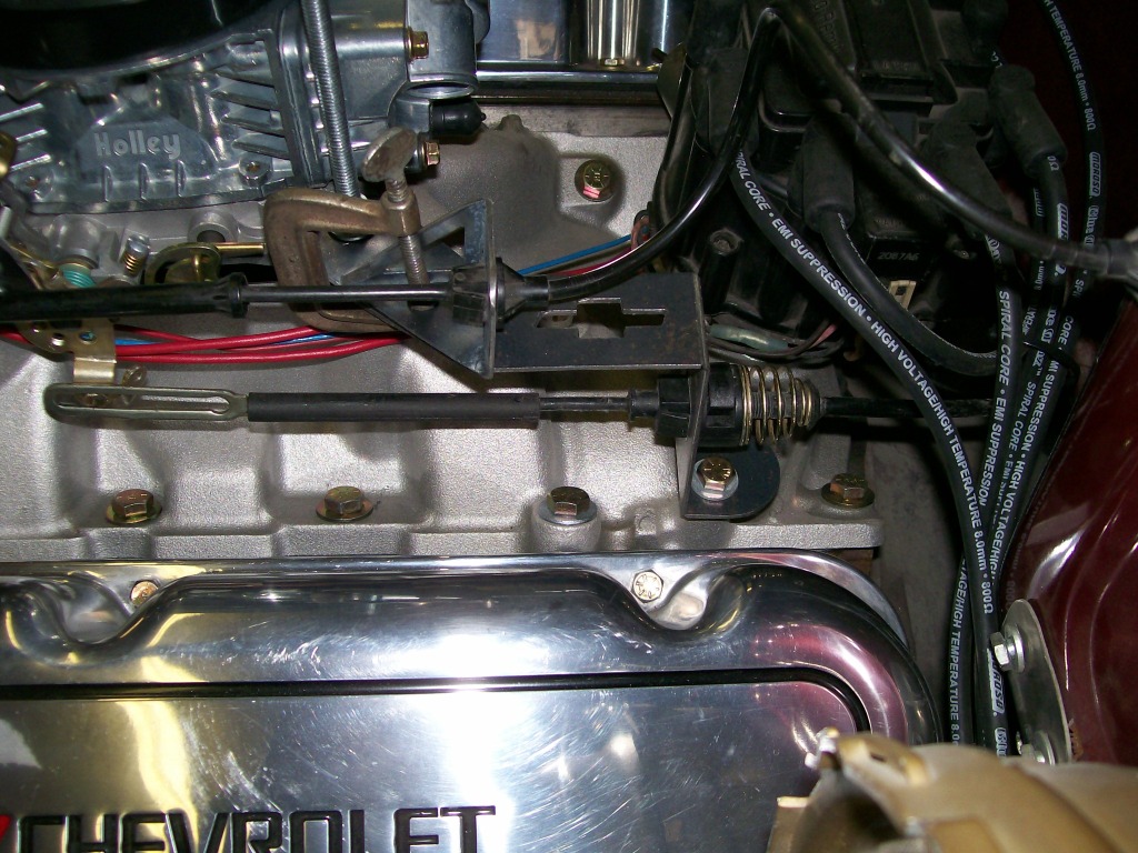
Back to the engine bay of the 57 Chevy, so far I've started the 396 but didn't have any linkage from the accelerator pedal to the carb or the transmission kick down cable hooked up either.
The engine was a small block before and the brackets don't interchange without adapting them. That's ok, it's extra work but at the same time it makes me stretch my imagination to make new ones.
I have to load more pictures but here is where the brackets start. First, a piece of construction paper cut to the shape, then the computer makes the cut.
9-19-2012
hannoman, I'm sensing a passion you have for your project, excellent.
I'd like to see more people with the passion you are showing. Once the passion is there then the patience is easier to find because you can invision the outcome and no matter what it takes to reach the end result, that's what you will make happen.
I don't know about the magazine cover, but thanks. What I like about the '57 Chevy project is the personal modifications I haven't seen on other trucks of the same year range. Original ideas are always a boost to keep working on a project.
If the 427 doesn't work out I am one who agrees with the 383 stroker. I have one in a car. I assembled it using the Eagle rotating assembly kit, 040 overbore, Edelbrock performer RPM aluminum heads. I've been extremely happy with this engine for 6 years now.
I'm stilll making the brackets to hold the accelerator cable. Not a major project but it's these small things that makes the overall vehicle look finished later.
I have to put a 90 degree bend in the bracket. My old way was to stick it in the vise and hammer it over. We've been here before, the bend is rounded, the metal shows the hammer indentations, ect.
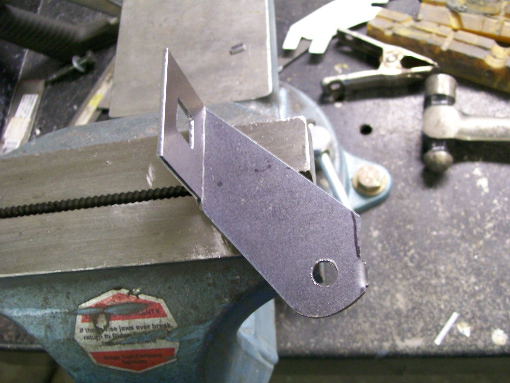
I'm using the same technique I used to bend the edges up on the leaf spring plates. Using the 3" cut off wheel I'm simply gonna cut across the flat bracket but only about half the thickness of the material. Now I can simply bend the material right at the cut zone.
Just showing the cut.
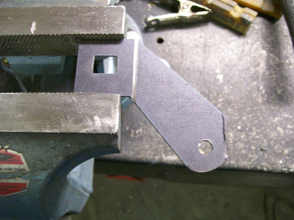
There we go, no beating, just a clean bend. I'm gonna have to weld a bead on the inside of the bend to get this strong again. If I use the mig welder I'm gonna end up with more of a weld bead than I want. I'll probably use the tig welder and try to fuse the metal back together. There is also going to be a triangluar gusset when done, so strength will not be an issue.
9-20-2012
You know, when I first saw the name on the build page, I thought to myself, I didn't post anything today. hmmmmm. Then I remembered my twin.

When you mention 16 years old, I'm going to take you back to the first thing to check. Thermostat.
Usually the problem with a water pump is the bearings go bad, or the inner seal between the atmosphere and the cooling system starts to leak. Usually you will see traces of coolant coming out of a small hole surrounding the shaft going into the waterpump. Since the impeller, the item that circulates the antifreeze, is press fitted onto the shaft, if the shaft going into the pump is turning you pretty well bet the impeller is turning. I have seen this problem, but extremely rarely.
Back to the thermostat. usually located in a housing where the top radiator hose comes out of the engine. This sounds like the problem. The thermost stops the flow of coolant from leaving the engine until the engine has reached a pre-set temperature. At this time the thermostat will open and allow the coolant to circulate through the radiator, cool, then go back into the engine.
When you say the radiator does not get hot, then I'd lead towards the thermostat not opening to allow the coolant to get to the radiator.
This is all based on the premise that the radiator is full, which I have confidence you've checked that already.
With any luck, this could be a $10 dollar fix, good luck.
9-21-2012
I know exactly what I'd be looking for.... I'd be looking at where you started, then how you ended.
What I mean is, assuming you're working with a mig welder where you have a choice of heat and wire feed controls, I'd be looking to see if you experimented with both of these controls to get the best possible weld.
Other than that, I'd be encouraging you the whole way through. Nothing better than watching somebody grow in their abilities.
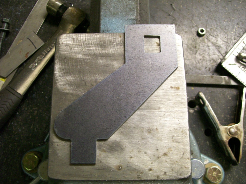
Moving forward on the brackets for the accelerator cable.
Next picture with a triangular gusset.
To sit and look at these pictures there seems to be no real thought process, but there is.
We have to concider the amount of movement that to provided by he travel of the foot pedal. If the foot pedal pulls the cable 2 inches, then we have 2 inches of travel to work with.
Now on the carburetor it is the distance from the shaft, or the pivot point that will that will determine where the cable will attach to the caruretor.
Another thing to concider....
Example, if the cable is connected to the carb close to the pivot point, it might require an inch of cable movement to go from idle to full throttle.
On the other hand, if the cable is attched much further away from the povit point, it might require 3 inches of cable travel to go from idle to full throttle.
We have to find the right distance from the pivot point for the driving situation. Driving off road will require a different set up than perhaps drag racing.
If I'm drag racing, I'm going from idle to full throttle as fast as possible, no in between, to floor it goes.
The opposite would be for rock crawling, throttle control is everything, so now I don't want a too quick responce. Plus with the bumps associated with off road, if the throttle is too sensative, just rolling over bumps would cause my foot to bump the pedal and the vehicle to respond with this movement.
Once again, it's one thing to build a bracket, it's another to design it to fit a particular application. It could be the difference between enjoying the ride vs being tense during the ride.
9-21-2012
WOW, would you check it out. Now we see why this is called the WWW. World wide web.
I'm gonna have to get the map out and see where this is going, very cool.
As you all know by now, I just work in the shop, snap the camera, and post some pics with a short explanation.
Here we go.
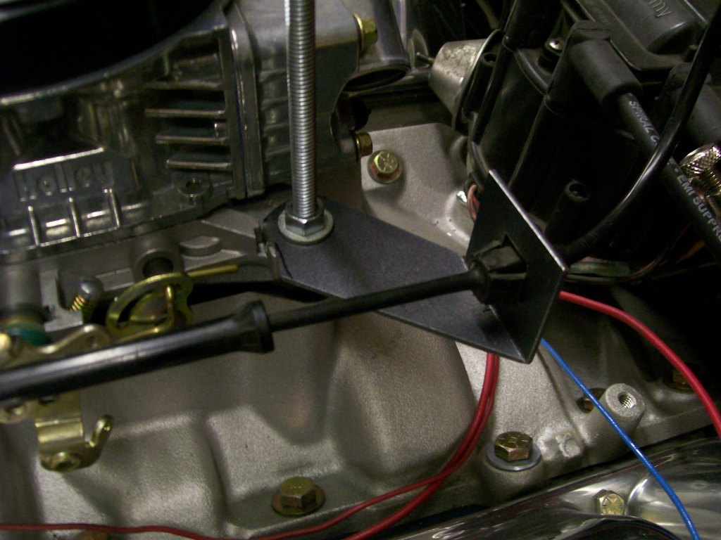
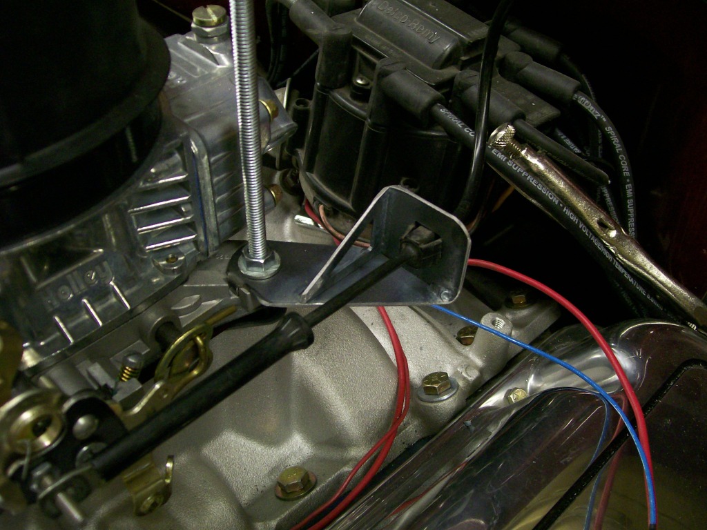
I still have the transmission kick down cable mount to make. A lot of the original stuff uses the manifold mounting bolts to hold a bracket for this. I really want to stay away from using the mounting bolts. There is a seperate bolt hole cast into the intake that will work for a mount. This hole is a good starting point, but I need two holes, the kickdown bracket will have some stress put on it, I don't want it to move later.
I decided to attach one end of a bracket to the accelerator bracket I already made, and the other end to the bolt hole in the manifold.
It's easy to build the bracket but it has a distance to reach from end to end. What I've learned, if you have a distance to cover, you have to keep the eye busy. In this case, I filled the distance with the Chevy bow tie.
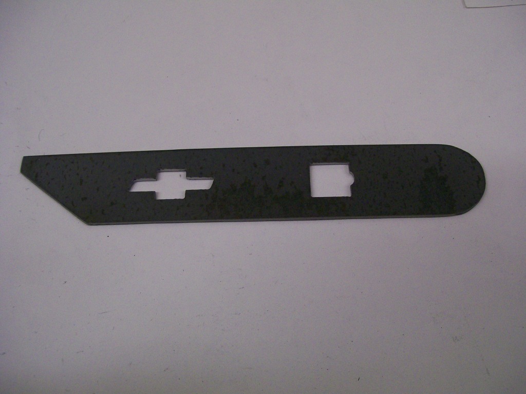
My point with the "keep the eye busy" statement is, imagine the bow tie not being there, it would a flat hunk steel with no character.
Most of the bracket is done, I still have to come up with a return spring mount. That'll be later, for now, I have a place for both cables to mount.