You must be logged in to rate content!
8 minute(s) of a 668 minute read
7-17-2012
Wow, the Willys, that paint hasn't looked that good in 20 years. That program sure works with shadows, that is soooo cool.
The construction paper mock-up stuff is gonna be cut from 16 guage sheet metal. I still have to create a substitute for the outer housing of the lightassembly.
There is a stainless bezel, and the red lens that I will reuse. The lens is actually a led light. This led light is making this project easier than if I used a regular light bulb. The led light doesn't require much depth as a bulb would need.
I needed a piece of pipe or something that is 3 1/2". The perfect material would be exhaust pipe. The closest I found was 3" so I got a foot of it.
I cut a section of pipe, then cut to open the circle. Then very carefully, spread it apart til it matched the bezel it's gonna fit into. Then took another piece to fill the gap and welded it in.
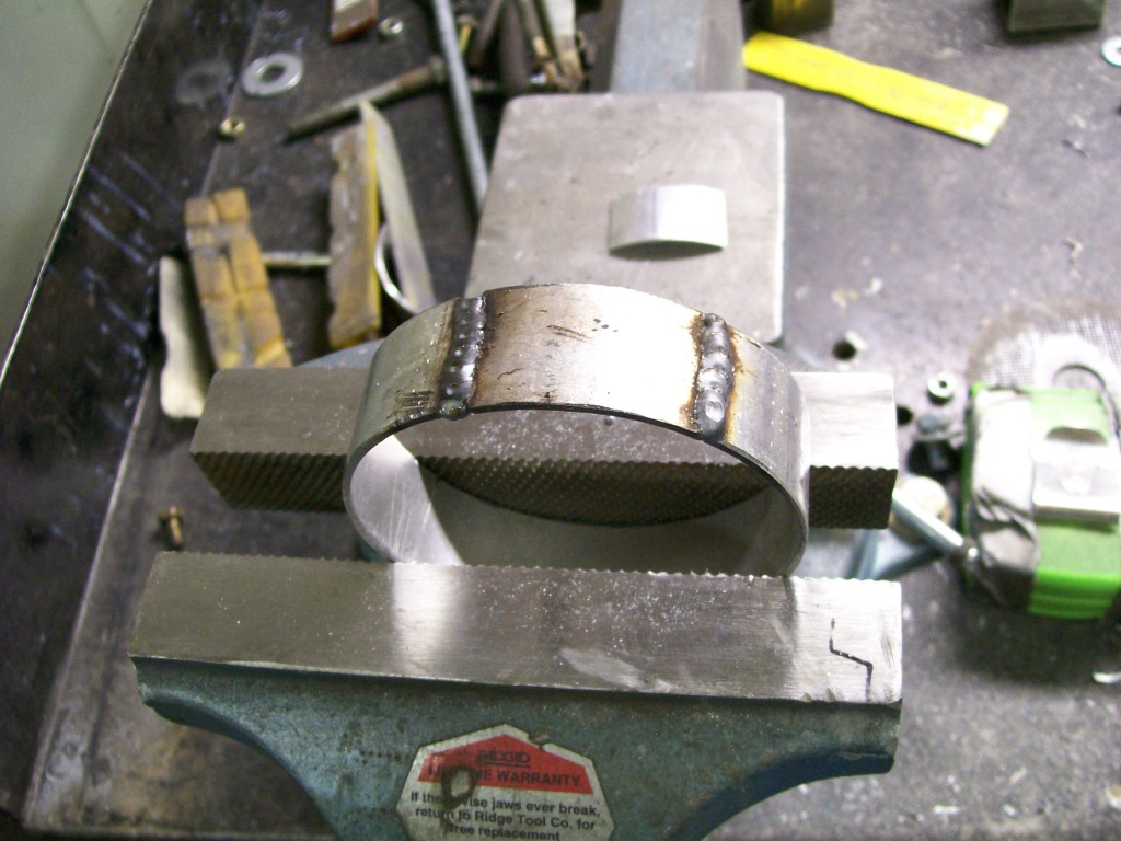
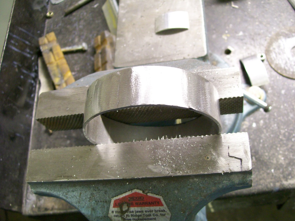
Once the welding was done, out came the 4 1/2" grinder. Now one solid piece.
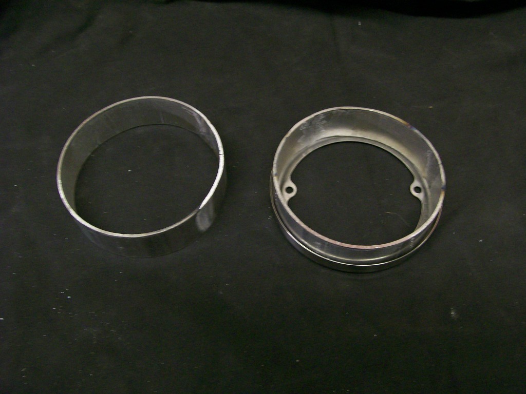
The one on the right shows the fit ito the bezel. Ok, that part taken care of.
7-18-2012
Ok, once again I go to the torchmate for the main cutting. I like pictures like this, it's as if I ordered a taillight relocation kit.
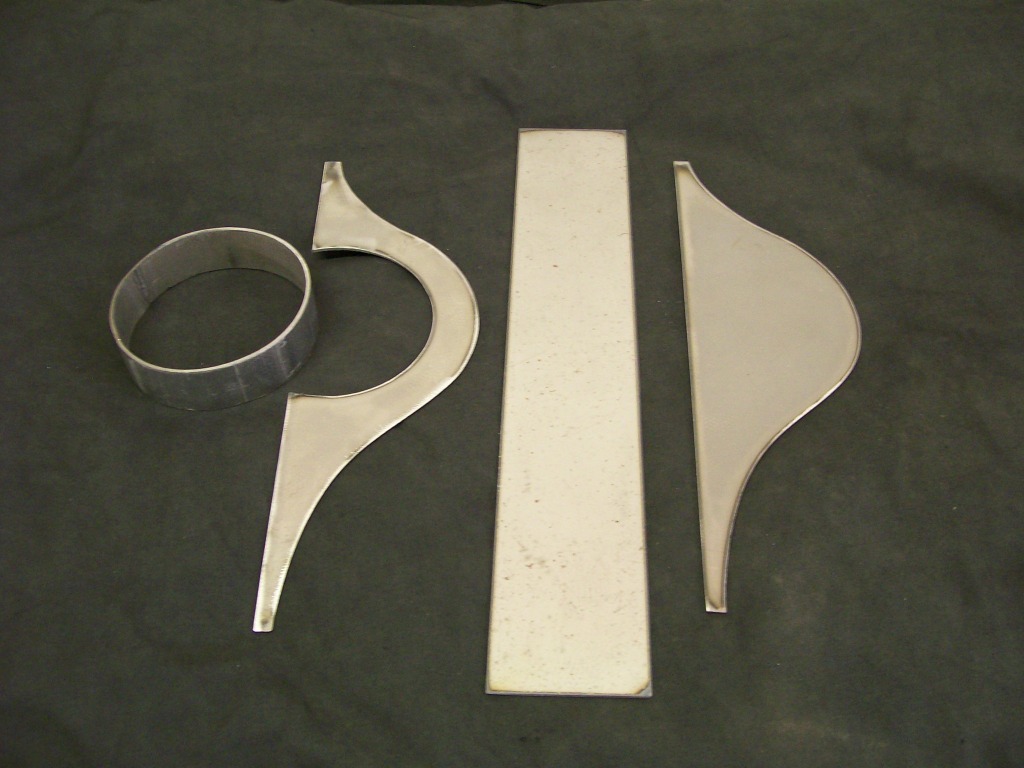
Earlier in this thread I've mentioned the idea of thinking ahead when cutting, drilling and grinding. This picture demonstrates thinking ahead.
I have two concerns with the front and back plates. They come to pointed ends. The torchmate uses a plasma cutter, when cutting the pointed ends, the heat from approaching the pointed end, then going away from the pointed end is a double heat in one place.
When I created the cut path in the computer I added materal to the ends. This way I am safe from overheating the pointed ends.
The second benefit is dealing with the heat from welding everything together. Once again, the point will want to melt away from the weld, with the extra material, the heat has somewhere to sink into.
This process of welding is a gonna be different than in the past. Now dealing with sheet metal, heat warpage and burn through is always at the forefront of the process. Certainly penetration is needed, but there is a very fine line of penetration and burn though.
7-19-2012
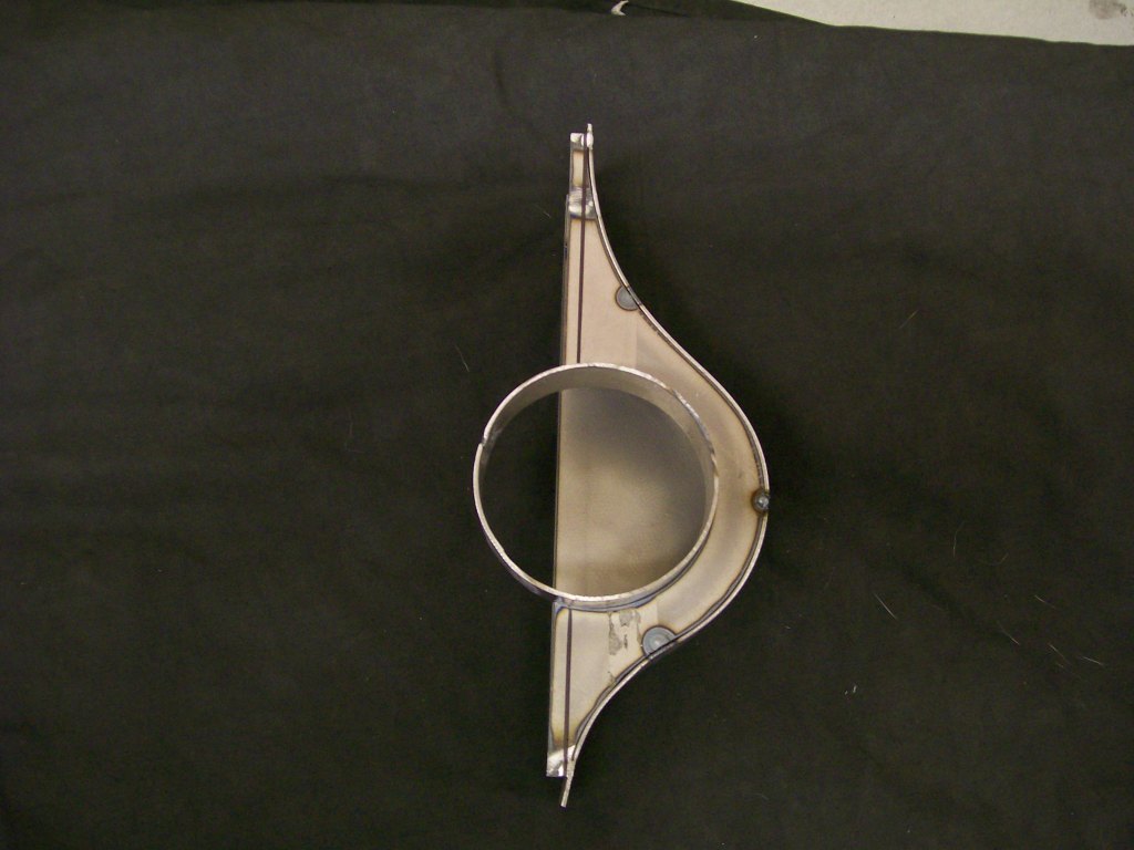
Time to see if the metal piece fits up as the construction paper one did.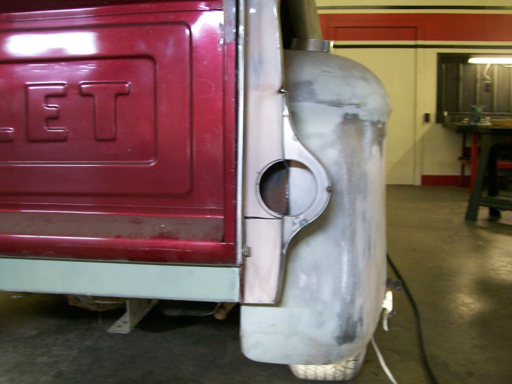
I like how the half hole I cut earlier in the bed side matches the new half hole in the new housing.
Now fitting the piece that the light and the original bezel will attach to.
Coming along nicely.
7-20-2012
Now for a test fit of the original light and bezel.
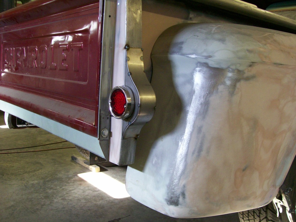
A look from the rear....
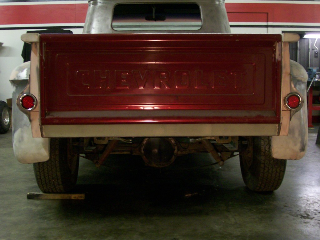
Now I realize I could go get taillights that are from another vehicle or I could get some aftermarket ones, but for some reason, I'm happy to use the original parts and blend them in. I still want to retain the 1957 visual with this truck.
7-22-2012
J-Quad, you're just a day ahead, but that's fine, I'm happy to answer.
The wiring will be better hid than it was originally. Where before, the lightswere hung on a bracket that reached out from the bed, which had the wiring exposed from the bottom of the bed to the light. Now the wiring will go from the bottom and be inside the bed reinforcement that I had blended the taillights into.
Coming up next, perhaps tonight, I will upload a picture. The picture will show a definite benefit of using the led light vs the original light bulb for this application.
rcweldon988, glad to have you check in.
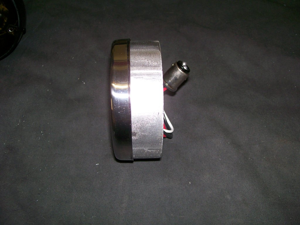
A quick picture of the advantage of using a led light vs a regular bulb.
The led light only uses the depth of the 3 1/2" tube that I'm using to hold the lense and the bezel.
If I used a bulb, I'd have the lense, then about a 1/2" space, then the bulb, then the socket the bulb fits into, then the wire pigtail sticking out the back.
New technology...
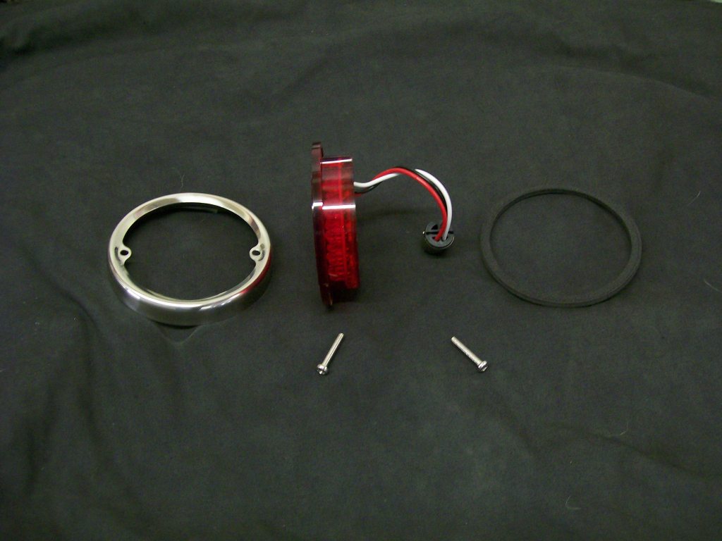
In the picture below, you can see a socket on the wires. This is so they can use the original outer housing, and this adapter just plugs into where the bulb would get it's power. I'll be cutting off the bulb adapter, and running 12 volts right to the wires.
Here are the pieces I'm using from the light kit. Basically everything but the outer housing.
7-23-2012
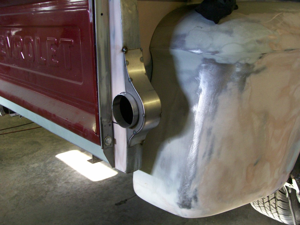
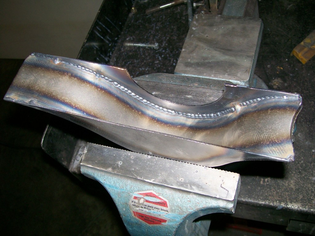
Welding time.
From the cutting of the pieces with the torchmate to now, where I'm ready to weld the pieces together I've tack welded the pieces and checked them for how they fit together as well as how they fit onto the truck.
The tack welds are a vital part of the assembly of these housings. A couple of good, evenly spaced tack welds will help keep the housings from distorting from the heat when final welding.
Next is the final grinding where the front, back and top plate come together.
When I cut the pieces, I cut the top plate to a size that will match the width of the reinforcement of the bed that the housings will be welded to. So the side plates fit under the top plate vs going to the outside of the top plate, this way, I know the width will match the truck when done.
Ok, Now the gap, or the meeting point of the sides to the top are on the sides and not on the top of the housings. I'm gonna grind with a focus of removing more material from the top edge to expose the meeting point of the plates toward the top edge.
Why the detail of grinding.... penetration dead center at the 90 degree edge. Plus I want fill, I'm gonna grind the edges smooth so I want material to grind away.
Yes, I'm gonna do the spot/stitch weld procedure again.") . Because the spot/stitch weld doesn't create the same heat as a continuous weld bead, I do the pre-grinding as I mentioned. By creating a thinner metal at the weld, I can penetrate just as well.
. Because the spot/stitch weld doesn't create the same heat as a continuous weld bead, I do the pre-grinding as I mentioned. By creating a thinner metal at the weld, I can penetrate just as well.
The outer weld of the housing. Plenty of material to grind and smooth the edges.
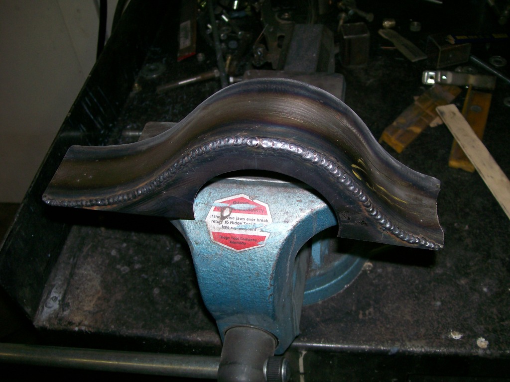
Here's the best part. Check out the penetration that happened. The inside looks like I welded it also. Now when I grind the outside for cosmetics, there is still an inside weld bead holding for the strength.
7-24-2012
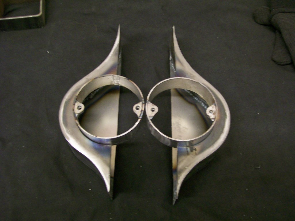
Somehow I think this could be a piece of art.
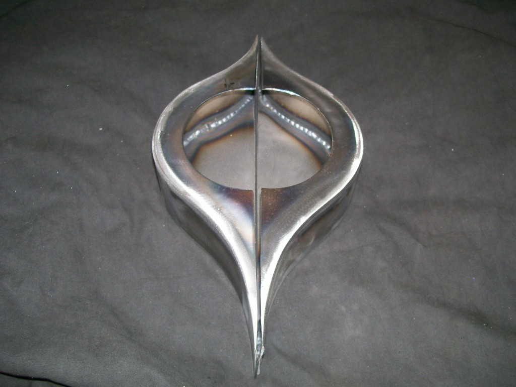
With all the pieces together.