You must be logged in to rate content!
12 minute(s) of a 668 minute read
6-30-2012
 Yes, I agree, I've gone to the Batman image myself. Because of the similarity I have tried different designs to get away from the look. but had to stay with it because it fits the purpose.
Once I finalized the constructuion paper cutting, I wasn't able to scan full images into the computer. The size was too large for a standard scanner. So, I traced the main corners and scanned them. Once I scanned a corner, I flipped the design, or what's called a mirror image. Now I had a right and left representation of each corner. Then, by measurement, tied the four corners together in the computer. Just to be sure I had everything right I measured and remeasuerd from the screen to the construction paper. The top and bottom plate are large, if I mess up on the design in the computer, I'm gonna waste alot of aluminum real quick.

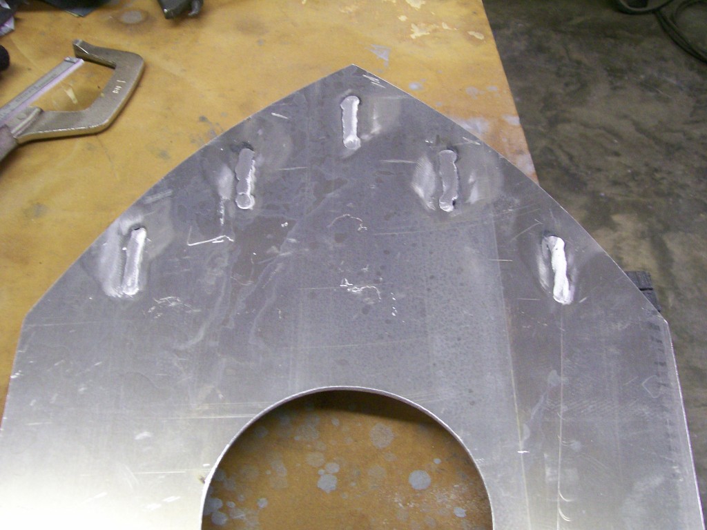
It's time to set up the torchmate. I used 3/16 plate for the bottom. I struggled with either 1/8" or 3/16" for the bottom. I don't like to do overkill, but I absolutely don't want any chance of flexing or warping, this is still an air filter with a purpose.
Here's the bottom just after the cut.
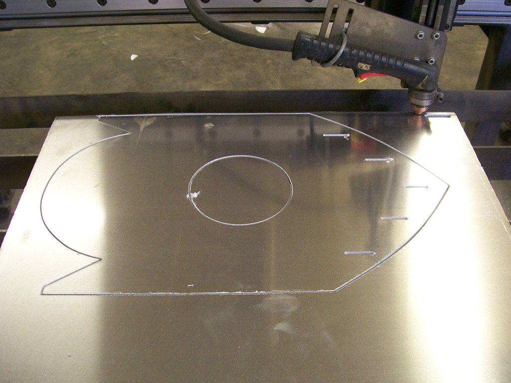
Now my nerves can settle, the cut went well, and it fits the carb exactly how I planned. During this build I have been very concerned about getting all the pieces located and in near perfect alignment. I have a fair amount of welding to do, and we've covered the issue of how things like to move during the welding process.
With this in mind, I made some cuts to help eliminate some of the alignment problems. Looking at the pictures, can anybody see the cuts that will help during assembly?
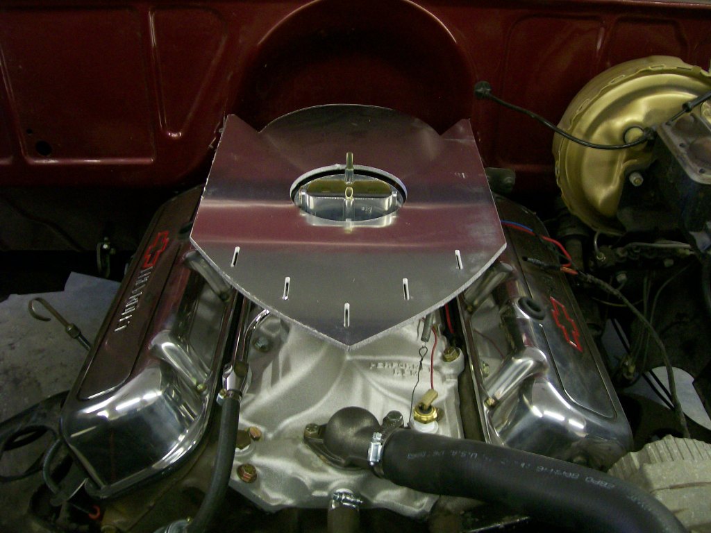
Yeah, that was an easy one. What it got down to was I was very concerned about getting the fins facing forward in alignment with each other. It would be easy if the front of the bottom plate was square shaped, I could easily use a square to mark for alignment. Along with facing forward, I need them evenly spaced apart and at a 90 degree angle to the bottom plate.
As I was creating the fins in the computer, it hit me to add a drop section to the fins. The drop is 3/16", the same as the thickness of the bottom plate. This was the answer for most of my concerns.
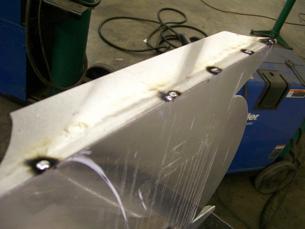
I still had to use a piece of angle iron to hold the fin in place. Yes, that is a razor blade between the clamp and the aluminum fin. It's only there so the clamp doesn't leave a mark in the soft aluminum.
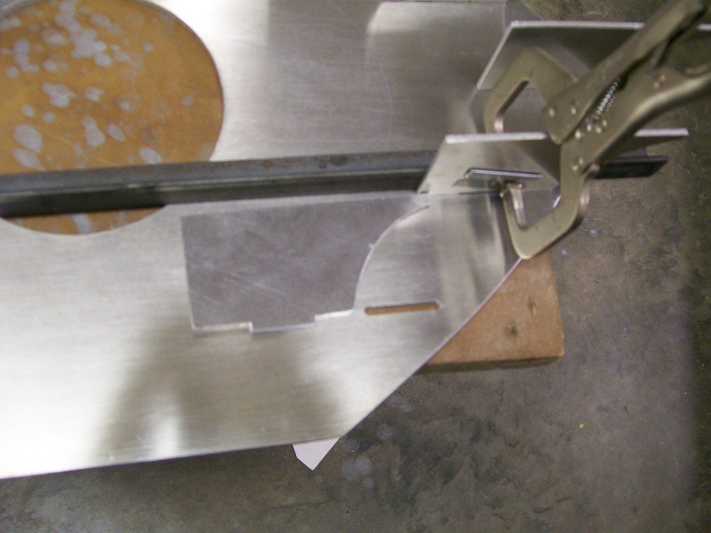
The second good thing about building the fin this way is it created a better way of welding the fins in place. I can weld from the bottom so there is not a weld that can be seen.
7-2-2012
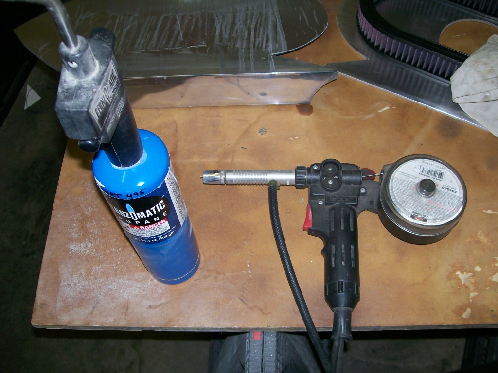
There is one piece of welding equipment we haven't covered yet. It is an attachment to the Mig welder. It's called a spool gun.
In a Mig welder there is a 11 pound roll of wire, once the trigger is pulled, the wire comes out of the handle along with a shield of gas.
Another option that lets you change from steel, to aluminum, or stainless steel, is a spool gun. It uses a much smaller spool of wire that is located right in the handle and uses the heat and feed setting from the welder, but you use this alternative hand device.
Also, the thin wire of aluminum is too weak to push through the regular hose and handle. Which makes the spool gun is very handy.
Using a Tig welder would be the optimum way to go, especially with aluminum. The tig allows you to throw alot of heat into the area before adding wire. This is the best way to go with alumimun since the heat transfers so quickly away from the weld zone.
I have come to the conclusion that my tig welder has an internal issue. Before I moved to this shop, I had circuit breaker issues, and I think something got messed up in my tig welder. This could be the reason my tig welding has sucked so bad.
I have to Mig the aluminum, I need heat before I weld, otherwise the weld won't penetrate very good, especially the start of the weld. Just to get some heat into the area I use the propane torch to at least get some heat in the area.
A picture of the spool gun.
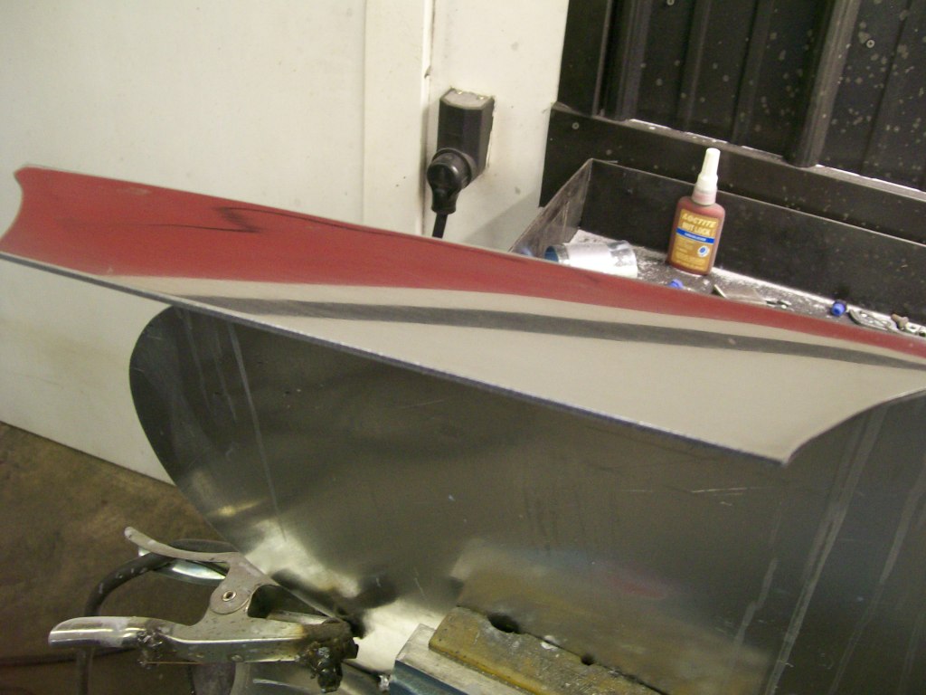
I love this picture, it tells a story of the function of the filter housing. I don't have to explain, I think it speaks for itself.
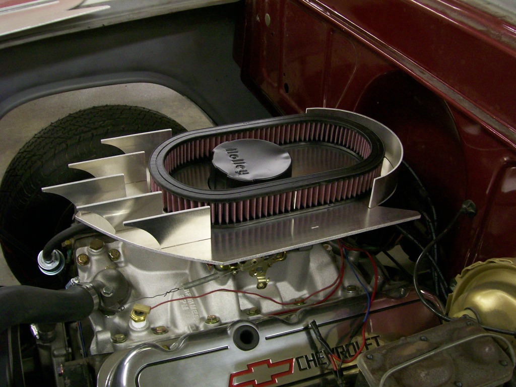
Yes, I do believe I'm gonna make my first air filter housing. You can tell I'm excited.
7-3-2012
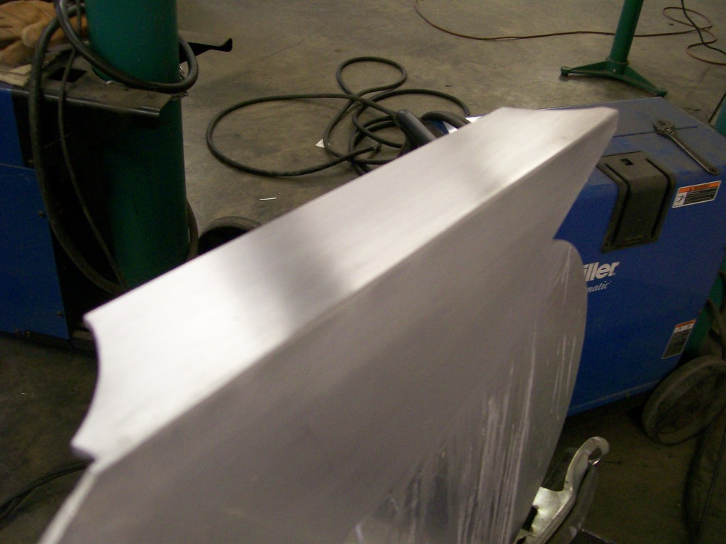
Now for the top cover to the air filter housing.
I had my doubts of being able to attach the side plates to the top plate and getting a nice polished finiished. Only way to find out is to get to work and do my best.
Aluminum is extremely sensative to weld when a cosmetic look is trying to be achieved. It doesn't give much warning before the material overheats and actually starts to melt away. I don't do enough aluminum work to stay familiar with it either.
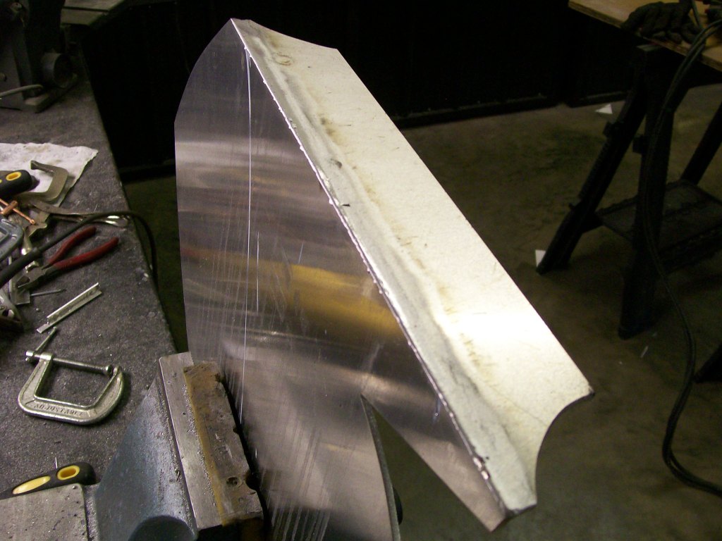
First off, I clamped the top and sides together with some angle iron. I already gound down the edges to create a "V" groove to fill while welding. I did a couple short welds on the outside to hole the plates together.
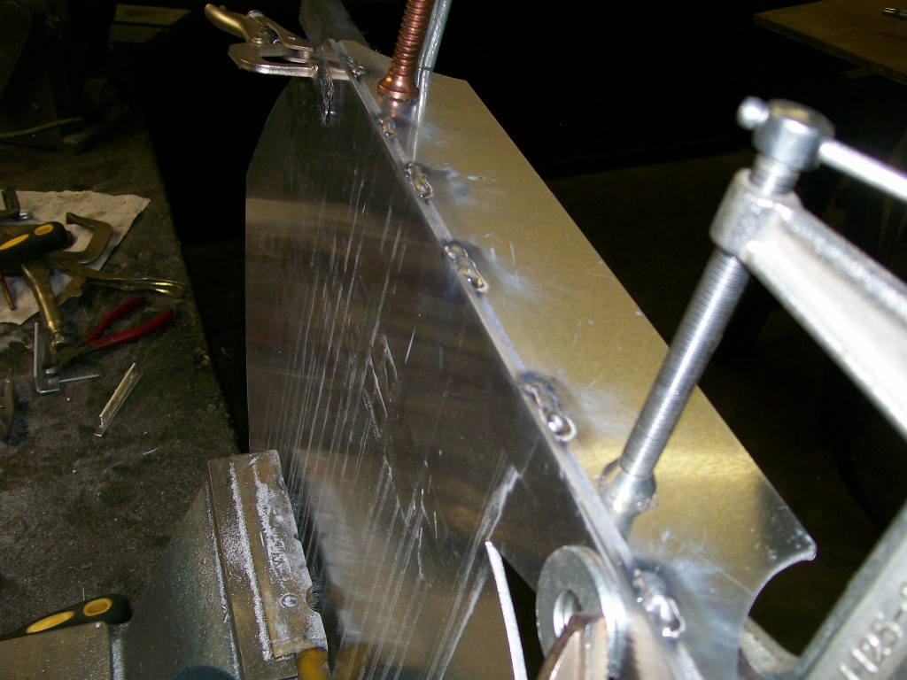
I then removed the angle iron from the underside. I checked the plates with a square. Once I was confident the pieces were in place, I ran a couple beads on the underside. Now with the top welds and the underside welds, I can go back to the top and fill the whole groove without the pieces flexing on me.
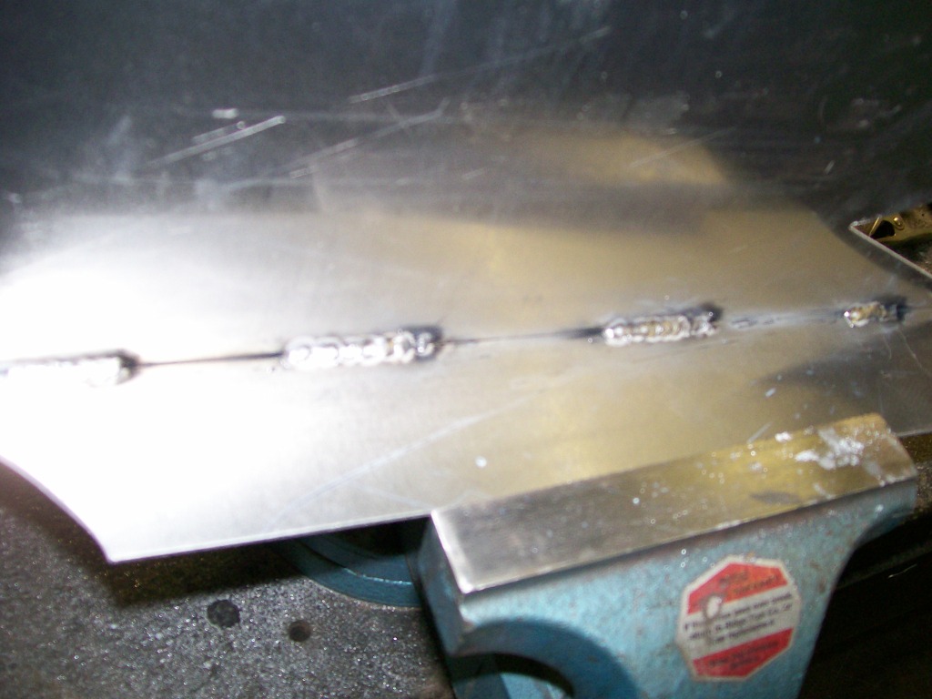
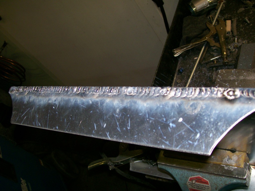
The aluminum is just like the regular steel I welded before. As I continue a long weld bead, it will sink in more and more. I'm looking for good penetration here, but I really need a good fill. Just as before, I'm gonna stitch weld all the way across the plate.
7-5-2012
RockZJ, You made it through all 70 pages. Who'd have imagined when I started, 70 pages.
I hope you enjoyed, and gained some ideas along the way.
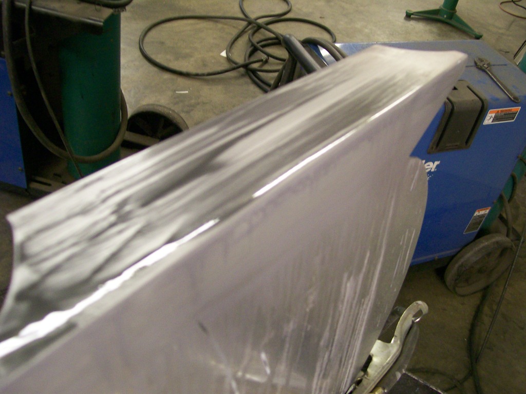
Now that the edge has been fully welded with stitch weld, just as I did with the gas cap, license light, trailer connector cover, by very carfully using the 4 1/2 " grinder with 40 grit flap discs, then 60 grit flap disc, I removed as much of the weld before going too deep.
As I mentioned earlier, when welding aluminum, it gives no warning when it is ready to burn away an edge. While I welded, I was trying to get the best penetration without burning away the edge. Looking closely at the picture above you can see small areas that got slightly burned away. I wanted the best penetration for strength, but I also wanted to burn into the previous stitch bead. I knew I was gonna be grinding, sanding and polishing, I didn't want a porous weld that was gonna have air pockets within.
Once all the low spots were identified, I simply spot welded the couple of low spots.
Now I'm close to the end. After grinding the spot welds, then I wrapped a paint stick with some 180 emory cloth. The paint stick kept the sanding level.
The next step was 400 grit wet sanding, this removed most of the deep sand scratches from the emory cloth sanding. There's a couple more steps yet to go, I was happy just to get to this point so far.
7-6-2012
Scooter402, Glad to still have you following along. I thought after the carb rebuild we'd lose you, thanks for the support.
spyder6, "aficionado", now I like that word, good stuff. I do have a piece that will serve somewhat as a memorial to my dad, I think you'll like the finish on it when I post it later.
Jeff88, Wow, I think you're right. I originally started wandering the site late in May. Then, as many have seen me write, I wanted to see the craftsmanship behind the fabrication of the projects. Then I thought, if I expect it from others, I better put up my own projects, so here we are, one year later.
I've mentioned wet sanding along the way. It's a matter of keeping a liquid flowing on the sanding surface that will keep the sanded grits from sticking to the sandpaper, rendering it useless. On a paint job on a vehicle, a warm bucket of water and a sponge usually does the job. I've found while wetsanding the stainless steel or this aluminum, mineral spirits does a good job. It keeps the sandpaper clean, it seems to have a very slight lubricating quality and it wipes off and evaporates fairly quickly.
Here is the mess that is left after wet sanding. I think I just sanded with 1200 grit paper here.
I still have to sand with 2000 grit paper, but I just had to rub a little polishing compound on the area to see how things are gonna look when done. I've got alittle more block sanding to do in a small area towards the back in this picture. Overall, I think we can see how this is progressing. Once a "v" cut edge, then machine grinding, then emory cloth block sanding, then 400 grit paper, then 1200 grit paper, then Mothers metal polishing.
The picture it taken at a different angle than the other pictures, I needed something that would show a reflection and the stripes on the walls work great for this.