You must be logged in to rate content!
12 minute(s) of a 668 minute read
6-6-2012
Yes, you are correct with the front driveshaft being freed up with this conversion.
This transfer case is called a full time 4x4 unit. The shift lever had 5 different positions.... starting at the front. 1) low range locked front and rear drive. 2) low range non locked front and rear drive. 3) neutral 4) high range non locked front and rear drive. 5) hight range locked front and rear drive.
With the spider gears in, position 2 and 4 would drive both front and rear driveshafts, and if I tried to turn the front shaft, it wouldn't turn freely, it had to work with the rear shaft through the spider gears.
Now however, in position 2 and 4, I can turn the front driveshaft freely. It is no longer linked to the rear driveshaft through the spider gears. Just as was mentioned, the new square pieces do not have the teeth to interlock with the front driveshaft anymore.
Yes, now it is truely a part time 4x4 transfer case.
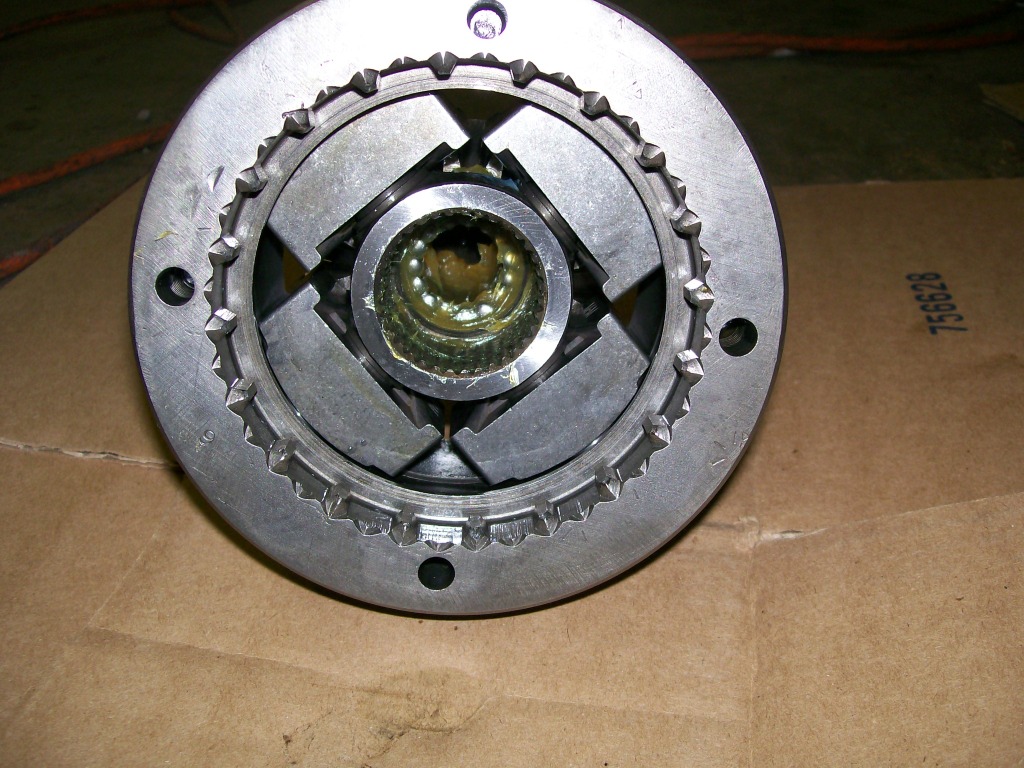
In the next picture I intended to show the 15 needle bearings, but the picture also shows the lack of teeth to turn the front drive shaft. The machined teeth on the inside of the outer shell does provide a way to lock the front driveshaft to it. This is part of the mechanism that locks the drive to the front driveshaftwhen shifted into four wheel lock.
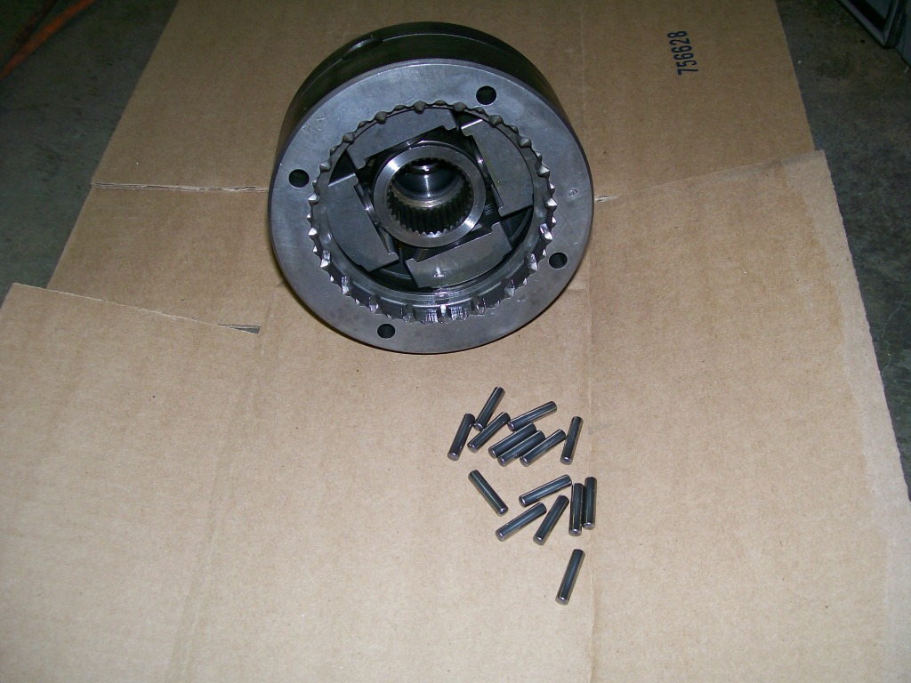
Having needle bearings used to scare me when they fell out. Oh no, how I get all of them back in place?
Clean the area and the needles with a degreaser and perhaps brake cleaner. Any old lubricant will keep you from getting the grease tacky enough to stick to the metal surfaces. Get some fresh grease and grease the bearings and where they are gonna be installed. Then start putting them in place. Smear more grease on the needles to help hold them, and you're done.
6-7-2012
Now you're going in places I'm not familiar with. But.... here's what I get from the few conversations we've had here.
You're not afraid to be curious, you're not afraid to dig for information.
I like the question about the front drive shaft being diconnected from the rear drive shaft due to the spider gears not making contact with the front drive shaft anymore. Keep on being curious and keep on learning.
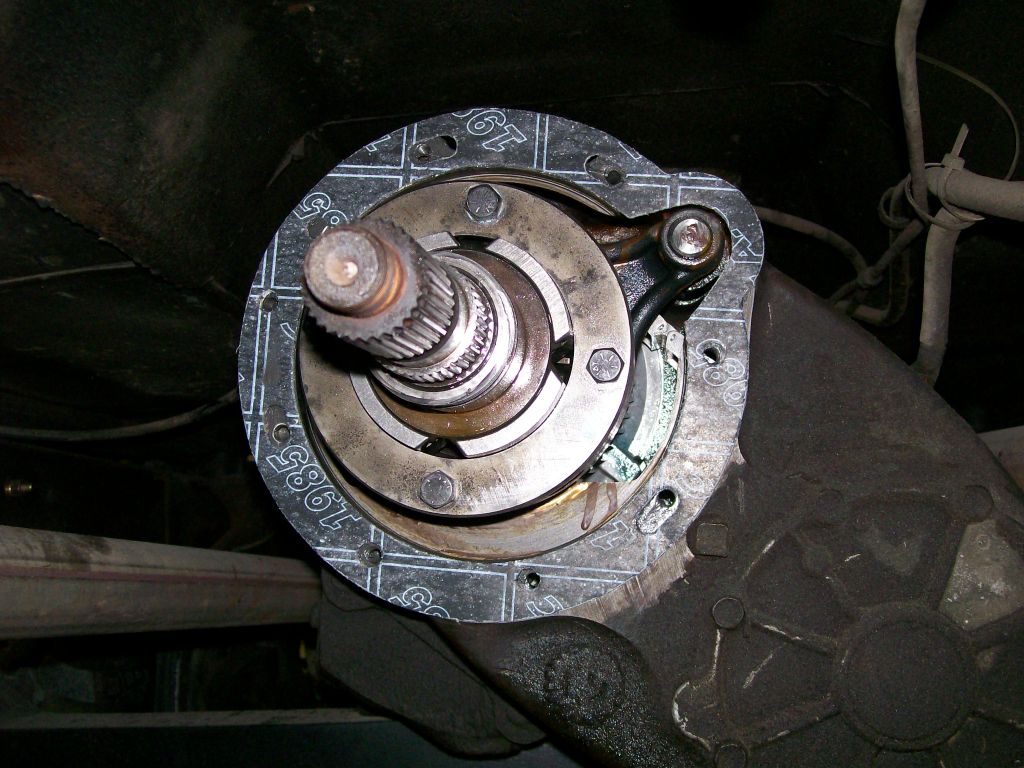
As for the transfer case I only have one more picture
It is merely putting the now one piece tailshaft spider gear housing back in place. After putting the tail shaft in place, the new gasket and the tail housing goes back on.
The tail housing does however require attention when installing it. The tail housing not only supports the tail shaft but it keeps the tail shaft from moving backwards. This means there may be some shimming necessary during reassembly. The kit does come with a couple shims.
Ok, now back to the 57 Chevy truck. With as much fabricated parts I've made so far, I decided not to top off the engine with a standard ole round air filter. They also have oval air filters, but once again, anybody can order one.
I ordered a 15" by 8" by 2" tall K&n filter element. I've got some ideas, but not exactly sure where I want to go yet.
One idea I've been kicking around requires the ability to engrave patterns or letters into aluminum. Since this is a memorial build for my dad I wanted to get his initials into the build.
Using the torchmate machine I discovered a way that I can do this.
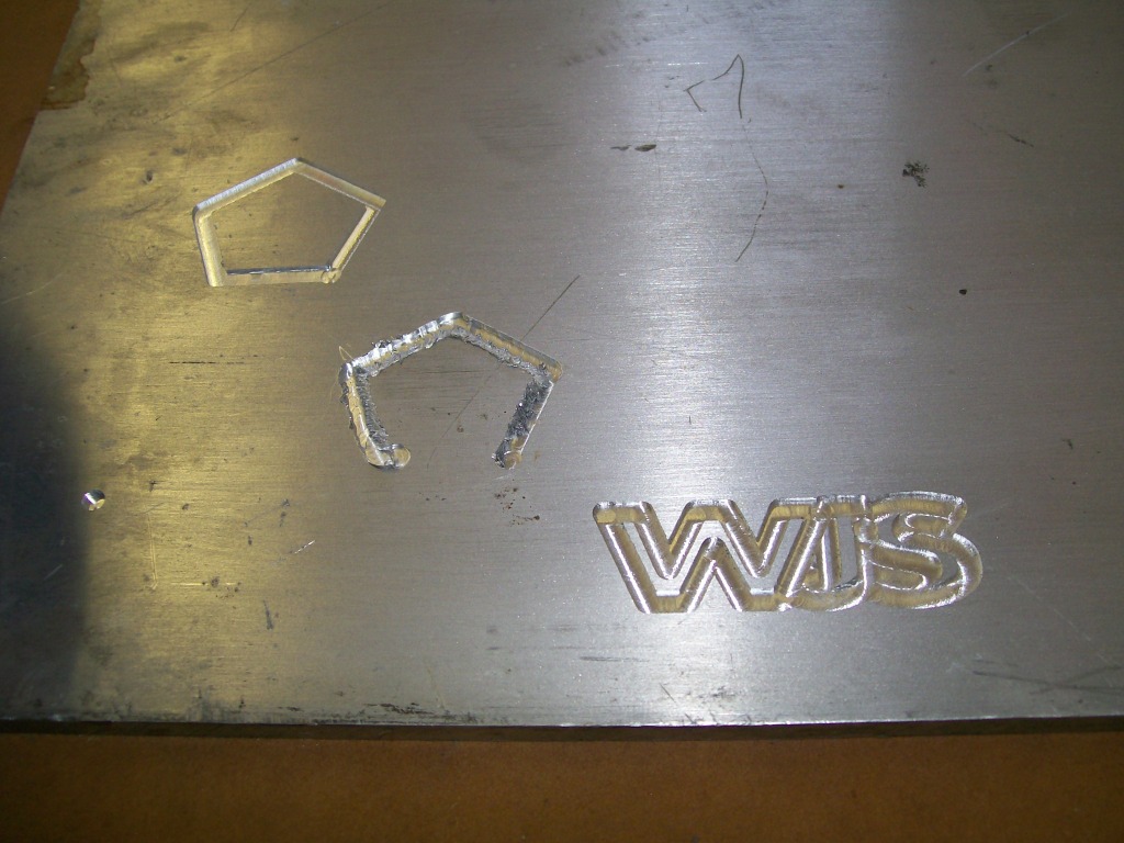
My first attempt was the un-finished diamond pattern cut, the cut was cluttered and messy. My second attempt was the clean cut diamond, very nice.
My third cut was the initials. Great... I got what I wanted. I made the initials very small and one issue was that the letters overrode each other, but it does show that I can adjust the cut and get the result I'm looking for.

Do to how the light reflects off the cut, the picture doesn't show the clarity of the cut. It is reflecting light shimmers back to the camera.
Hmmmm. now it's time to get creative, not always my best talent , but I'll do my best.
6-12-2012
Been in a thought process lately on the 1957 Chevy truck. I know I want to do a two tone paint job, just not sure how I want to lay out the colors.
I'm not ready to paint yet, but it helps to know now since all the body panels are still assembled. I've been using some 1/4" tape to lay down some lines to give me an idea of how I want to paint it later.
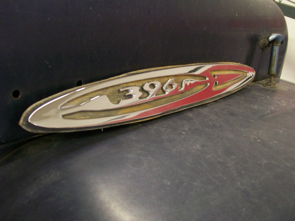
Beyond the paint issue, I've pretty well finished the fender emblem for the passenger side. I still need to make the one for the drivers side, but now that I've fgured out how to do it, the next one will be easier and a little more refined when done.
For a look at the one I have done, I have a picture. The reflection is the striping that is on the inside walls of the shop.
Also the waves in the reflection have been pretty well removed since this picture was taken. I wrapped a paint stick with 1200 grit, then 2000 grip wet sand paper to block sanded these areas smooth. The polished it back to a glossy finish. These areas are where I welded the studs for mounting.
On the other side of the shop is the 1950 Willys. Back in January when I reassembled the brakes and was bleeding them I noticed the master cylinder seemed to move as I was pumping the brakes.
Upon inspection, I come to realize that the booster and master cylinder assembly is bolted to the firewall sheetmetal. This single layer of sheetmetal has too much give to support the brake system as it is.
In most vehicles there is a double layer or some kind of reinforcement to support the booster and master cyclinder. Since January I've been thinking of a quick easy way to keep the booster/cylinder from moving under braking.
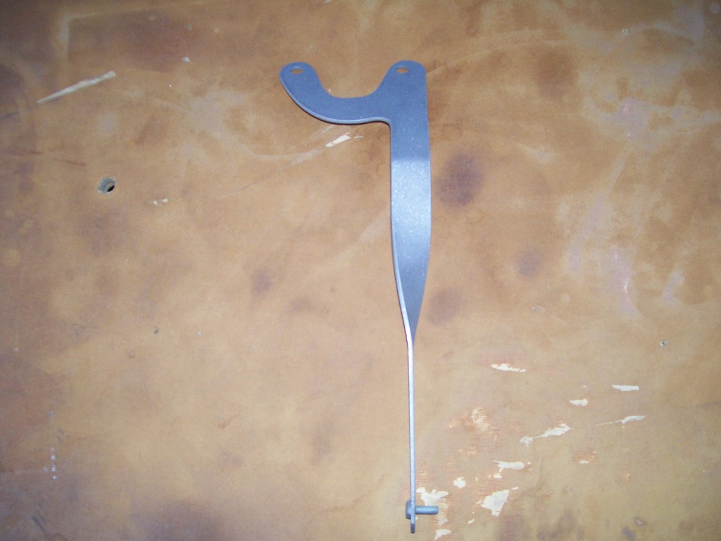
My idea is a bracket that will attach to the two bolts that hold the cylinder to the booster. Then reach down to a solid structure below. This is what I did, and what a difference, the pedal responce is much better now.
Simple bracket after sandblasting.
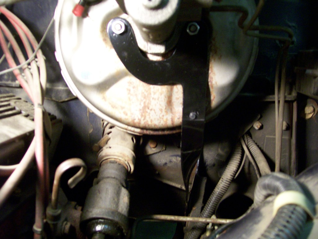
Now bolted in place. It does nearly touch the booster where they both meet at the bottom of the booster. I had a rubber bumper left over from an atv that went between the plastic panel and the metal frame. I drilled a hole and mounted this rubber bumper to the bracket. Now it can touch the booster with no ill effects. It's these simple little things that bring completion to a project.

6-17-2012
Not alot going on in the shop for the last week or so. I am getting excited about getting the '57 chevy truck at least to a drivable unit. Meaning I have to do alot of wiring, brakes, rear suspension, and at least getting the body in primer.
Back in fall when I primed and painted the frame of the Willys I was temped to use epoxy primer vs the acid etching primer I've been using for years. Now that I've pretty well used the last of my old primer, I've purchaed some epoxy primer to use on the "57 Chevy body.
My first place to spray and get a feel for epoxy primer will be the insides of the front fenders. What a perfect place, there a good amount of sheet metal, I can sand and experiment with dry times and adhesion with out worrying about making a mess that will be seen later.
First, I have to get to good clean sheet metal first. As I've mentioned before, when this truck was restored over 20 years ago, there were steps that were skipped over and this was in the body work along with some mechanicals.
Looking at the last paint work, there was rust coating that was painted over. I have no idea why, just spend another hour and scrape the old crud off. Now I get to scrape off the old crud.
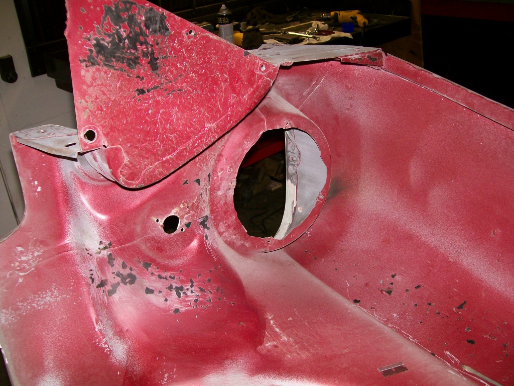
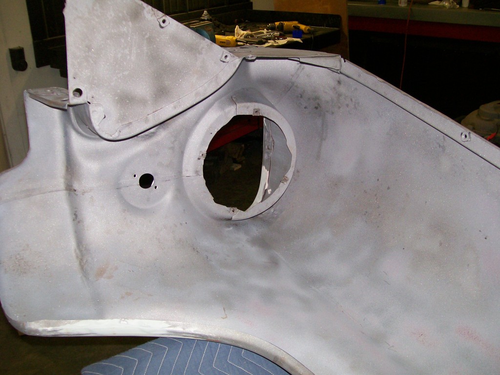
Once I scraped off the crud, I took the fender out for it's sandblasting, now I have the perfect surface for priming.
I must forewarn..... sandblasting the inside or outside of fenders, doors, under hoods ect, can result in warping the sheetmetal. There is a heat and an impact being applied while sandblasting, this can stretch the sheetmetal, especially where the metal is straight or flat. I see eastwood products has a soda blaster available that is not as harsh as sandblasting. I myself, have not tried it yet.
6-19-2012
Back to the air filter on the 57 Chevy truck. As I mentioned before, I'm not gonna settle for a round air filter, just too common.
Then I sat down and on the computer I came up with an oval design. I was gonna use an oval filter and cut my own oval housing with the torchmate and personalize it.
I've been going through picture after picture of 55-57 Chevy trucks looking for two tone paint ideas. Along the way, occasionally I'd see a picture of hoods up and I see the air filters. Even when I saw the standard oval filter, they just didn't do anything for me. I just have to try something different.
Know this, I have other vehicles that do use the round filters, so I'm not bashing them, I just want to push my abilities and go beyond the norm.
With that said, I'm trying something I haven't done before. So.... we all can learn from my failure, or my accomplishment.
Next thought... Paul jr. from American choppers made the perfect statement that really stuck with me some time back. I don't remember word for word, but the thought was, when building and fabricating we ride the edge of complimentary vs comical. What we build can either add to the outcome of the project or just add weight to the project.
I want to build a air filter housing that will fit the aggressive old style look of the truck. It's gonna depend on the size and cuts that will determine whether it is complimetary or comical when done.
Also, in the past I've thrown away projects that just wasn't what I was looking for, hopefully this will stay out of the garbage can.
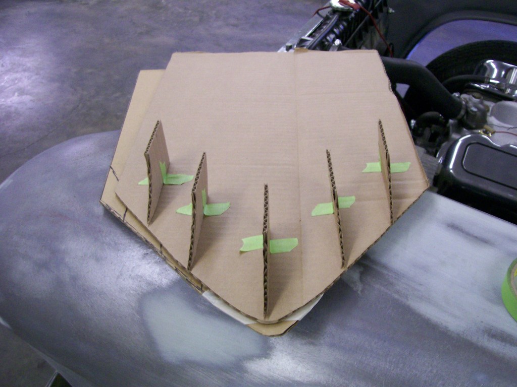
First design factor was to keep the filter element out of view. I didn't want to see the filter first, I want to see the housing first and know there is a filter inside.
I hold onto empty boxes for this exact reason.
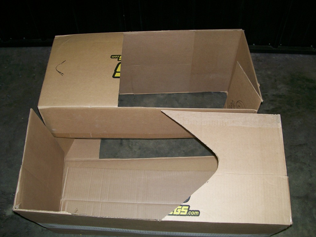
The idea of using carbboard first is that it's alot cheaper and easier to cut and reshape than making this out of aluminum first. Plus it gives a visual concept before I commit to any design.
After cutting a bunch of pieces I started to tape everything together.