You must be logged in to rate content!
7 minute(s) of a 668 minute read
6-3-2012
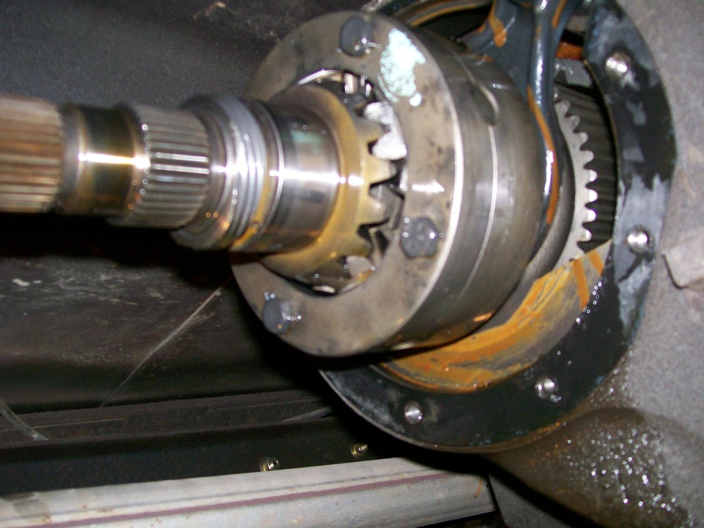
Similar to how the Dana 60 axle carrier split apart earlier in this thread to release the spider gears, this transfer case carrier also splits apart.
Once the four bolts are removed, the unit splits apart. Now we can get to the cross and the spider gears.
Please note in the picture you can see about where the two halves are nearly touching, you can see small notches cut into each half. Always, I say always, when dissasembling any parts that are machined pieces, mark, or check for marks so you know to put the pieces back together properly later.
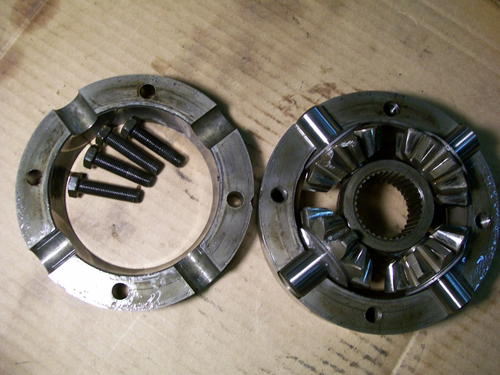
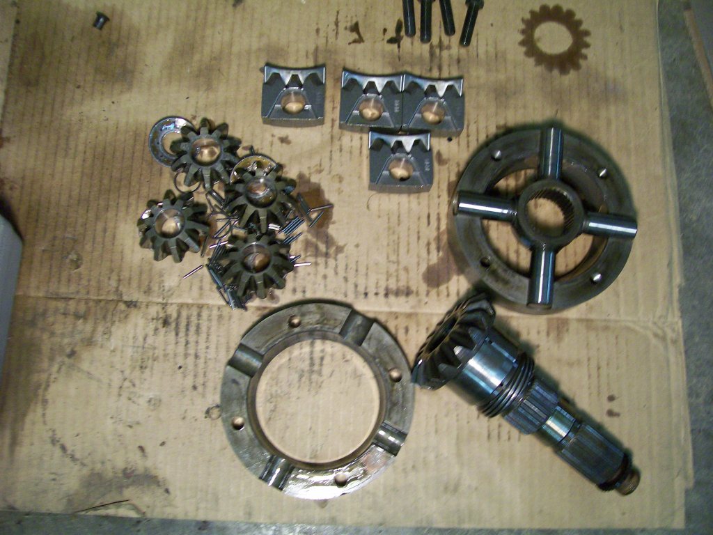
Now the spider gears can be removed from the cross. Looking at the picture below, I placed the "square" replacement gears in the picture. By simply looking at this picture it's hard to see how this all works out. Once I get the next couple pics loaded, it'll make more sense once I put the pieces together.
6-4-2012
 "Lincoln lockers" I love it.
Scooter, first time I've heard that term. For those not familiar, in the rear end, the spider gears make contact with each other. So if you have an application that you're strictly off road, be it drag racing or dirt, mud rocks ect. and getting power to both wheels, one option is to weld the four spider gears together inside the differential. (Lincoln welder) This will take away your ability to turn sharp since the inside and outside tires will rotate at the same speed. But as for sending power to both wheels at all times, it works.
Other options would be to use a posi-traction unit or what's called a spool. The posi I covered earlier in this thread. A spool is a replacement carrier that the ring gear bolts to similar to an original carrier. The difference being.... it has no spider gears. The spool has splines that the axles fit into. Now the power is transfered directly from the ring gear to the axles without spider gears.
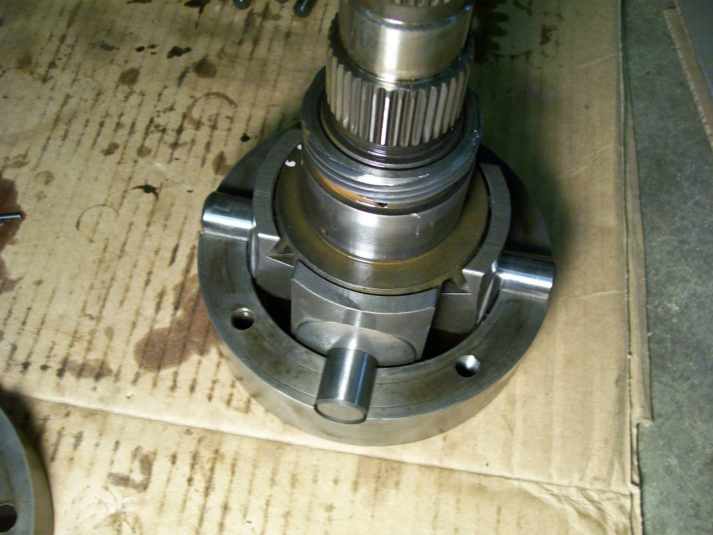
Talking about spider gears, the ones in the transfer case are now replaced with these square gears. The square gears slide directly onto the cross where the spider gears were. The needle bearings that were in the spider gears are no longer needed since this whole set up is gonna be one locked up unit now.
In this next picture the pieces are inplace.
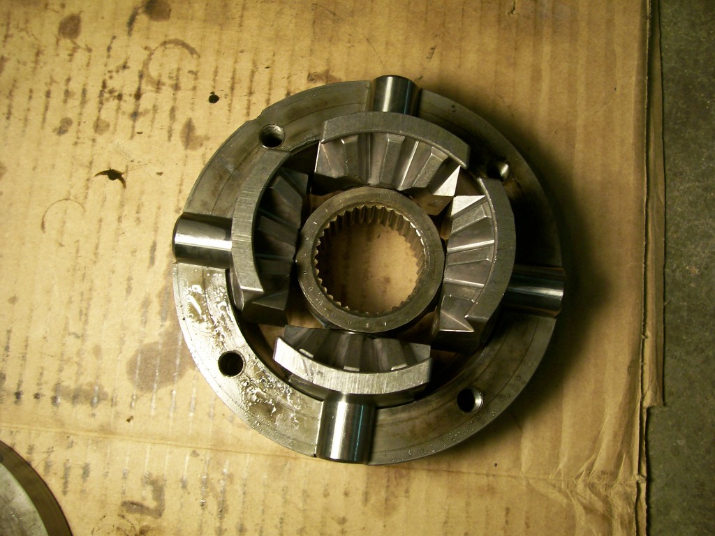
Now I've placed the tailshaft inplace with the square gears. What is neat about this arrangement is the square gears not only have the teeth to hold the tailshaft from turning, the square gears have the shoulders that support and encase the tailshaft so it cannot move forward or backward when this is assembled. It is as close to a solid unit as it can get when done.
6-5-2012
krabby124, hmmmm, good question. I believe way back in the '70s when these were created, the idea of a SUV was just beginning. Up to this point most 4x4 vehicles were trucks and jeeps built with a purpose of going off road and doing chores.
Then the idea of the SUV came along, a 4x4 that will spend most of it's time on the road and used as a primary driver.
The idea of having to figure out what lever to to pull to engage the four wheel drive and get out to turn the front locking hubs was out of the question. Remember, this is way before electric solenoids and switches to engage the 4x4 system as we have today.
So the way to get past the problem of the front axle turning at a slightly different speed than the rear axle and the transfer case with solid gearing taking the abuse, was to install a set of spider gears. Something as simple as the front tires wearing faster that the rear tires, thus changing the outer diameter of the tires is one way that the transfer case has to make up this difference.
What happened along the way was it used more fuel with this transfer case. Plus on sharp turns you can feel the front turning u-joints working under a load. Basically, it was a very usefull unit, it was just a little too controlling.
So.... one quick fix was to install front hubs so you can now disconnect the front driveshaft from driving, or being driven by the front wheels. This is where I've been for years, but there has always been a weak point inside the transfer case..... the spider gears. Without the power going to both the front and rear wheels, because the front hubs are unlocked, these spider gears are being abused by only applying torque to one side, this side being the rear
wheels.
This brings us to where this kit takes care of the weak link, (spider gears). The idea is to convert from using the spider gears, to a solid tailshaft design. Instead of buying a tailshaft and the spider gear carrier that we see in the pictures, this company has this kit that replaces the spider gears with these locking teeth. These teeth do not do any turning at all, the teeth you see are only to hold the tailshaft from turning within the carrier, as it did before.
Now there is no slop at all when shifting in to first or reverse gear, and the weak link has been removed. Installing this kit is more a maintanance procedure, the way it was did work, it was just a matter of time before the spiders or the needle bearings they rolled on started to break apart and create bigger problems.
lclark2074, no, they do not have teeth on the other side. The teeth you see on this one side are there to interlock with the tailshaft teeth. This interlocking process is going to firmly hold all these parts together so there will be no more slop as there was with the rotating spider gears.
This next picture shows how things have changed. Before, the tailshaft rested against the 4 spider gears, now the tailshaft is more of an integral part of the old spider gear housing. The only other choice would be to have a whole new tailshaft made that replaces the tailshaft along with the spider gear housing. This kit was around 50 dollars, I do believe there is a replacement shaft out there somewhere, but I'm sure it is much more expensive.
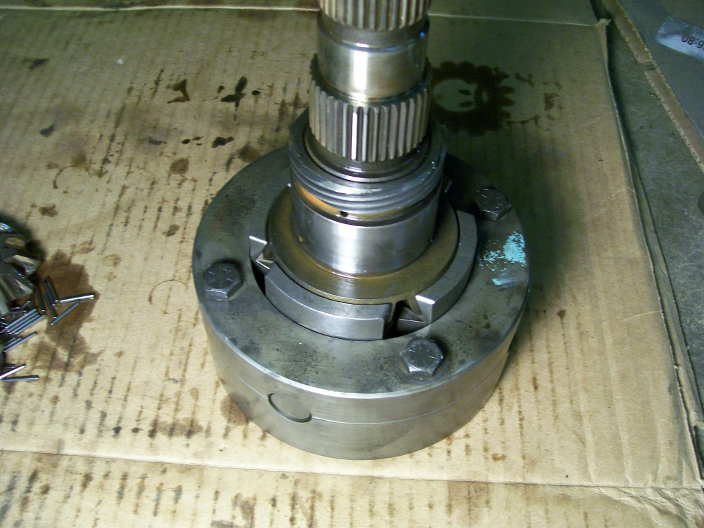
I'm gonna repost this picture again to show how the original set up was. Where now after the conversion, the tailshaft is an integral part of the spider gear housing, the old set up had the tail shaft resting against the teeth of the spider gears.
