You must be logged in to rate content!
9 minute(s) of a 891 minute read
3-3-2018
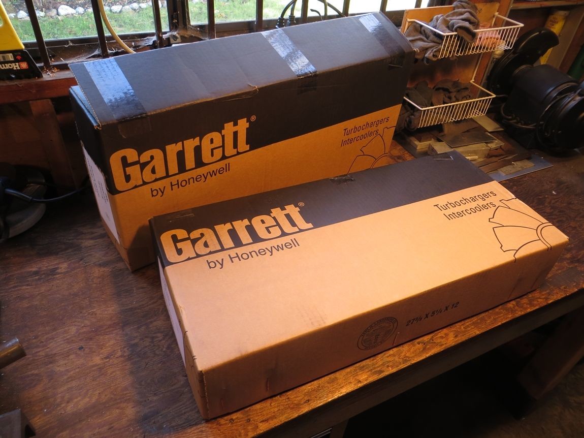
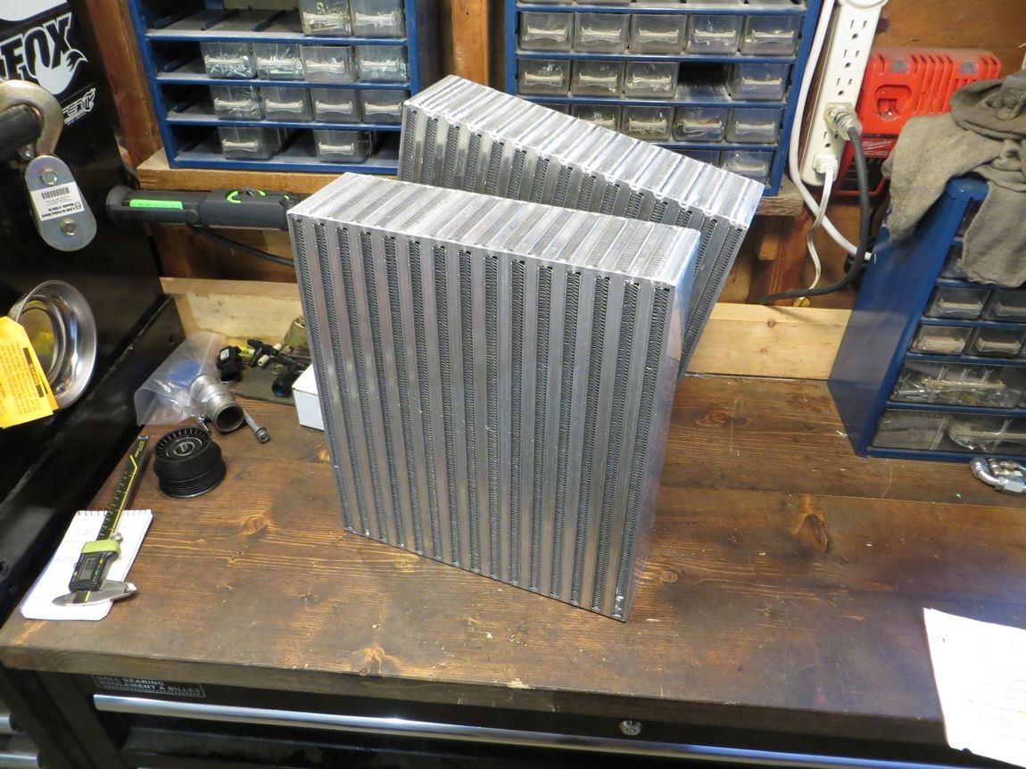
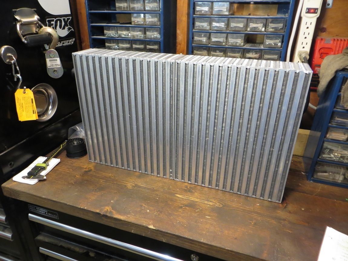
So one of the last big things to get was the intercooler core(s). I really wanted Garrett, because the best, but the range of Garrett cores available in the aftermarket is pretty limited. I originally wanted a vertical flow core matching the radiator core width of 28", and somewhere in the neighborhood of 12" high. I ended up deciding on a pair of 12"W x 14"H x 3.5"t cores, that I'll weld together as one vertical flow 24"W x 14"H unit.
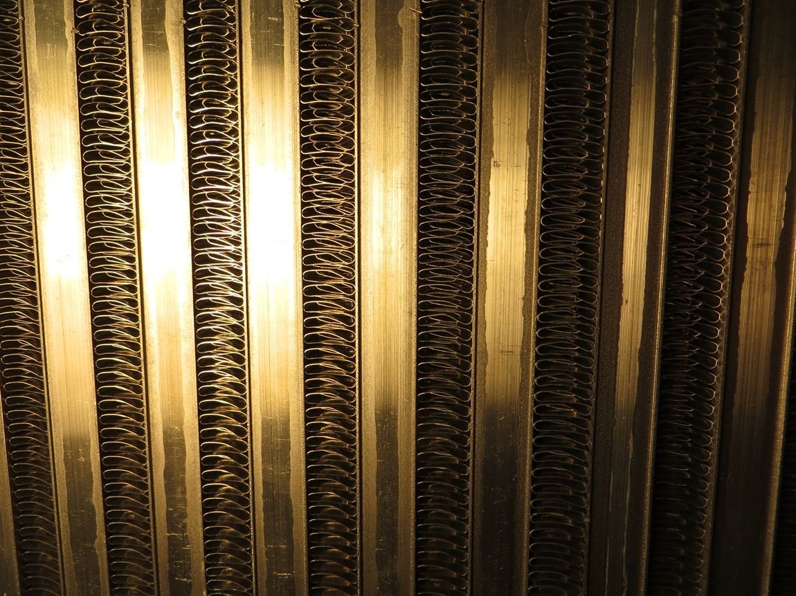
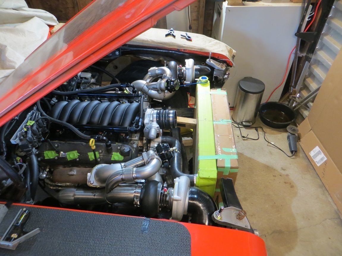
The reason for me being fixed on using Garrett cores, is the reputation of excellent cooling on their high efficiency "GT cores". Garrett goes about this by having lots of these alternating/staggered/louvered "turbulator" fins, both on the outside vehicle flow and the internal charge air flow. Other brands claim to have this, but at what pressure drop or internal restriction.. I do not know. Would rather pay the price once in the beginning and do it right.
The flow thru the 3.5" width seems pretty impressive for the fin density.. I blew thru the core very lightly (think an 80 year old blowing out birthday cake candles) and the wind force was strong on my hand on the backside... I don't think this 3.5" core thickness will affect the radiator airflow much based on this super subjective test.
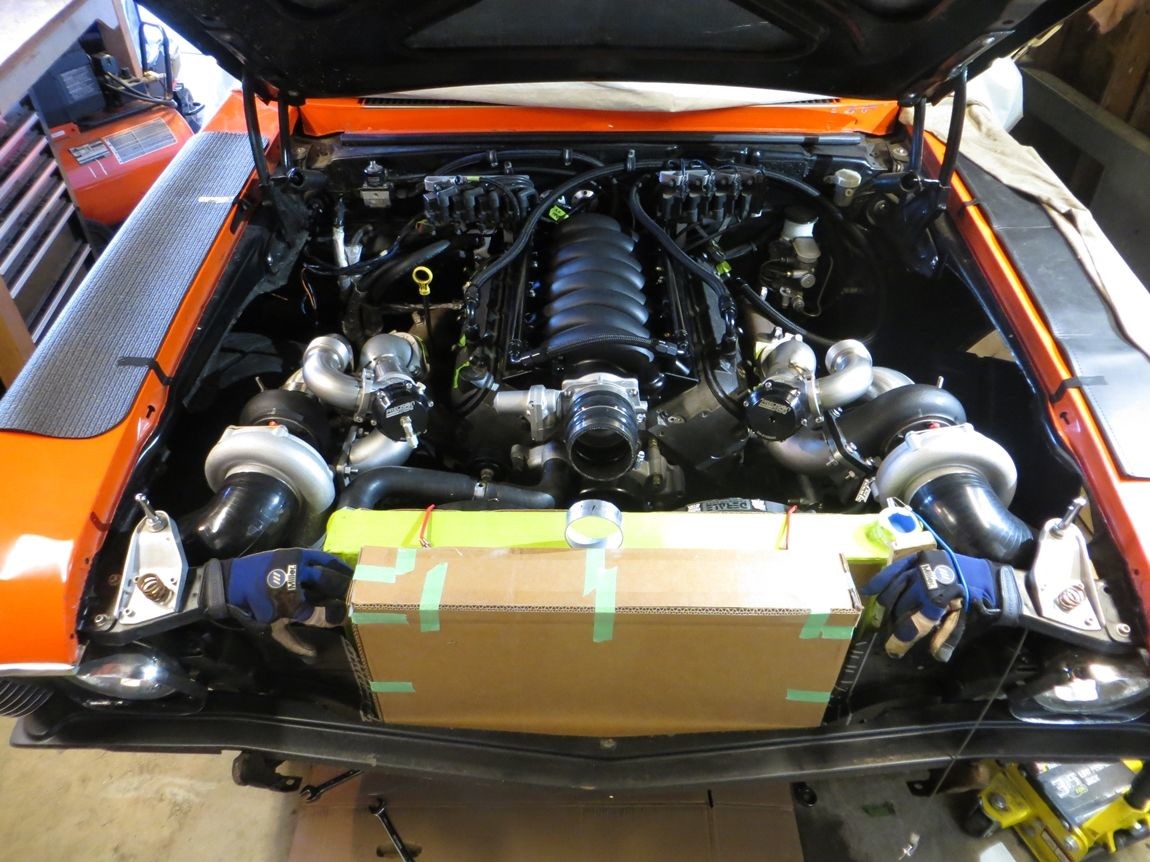
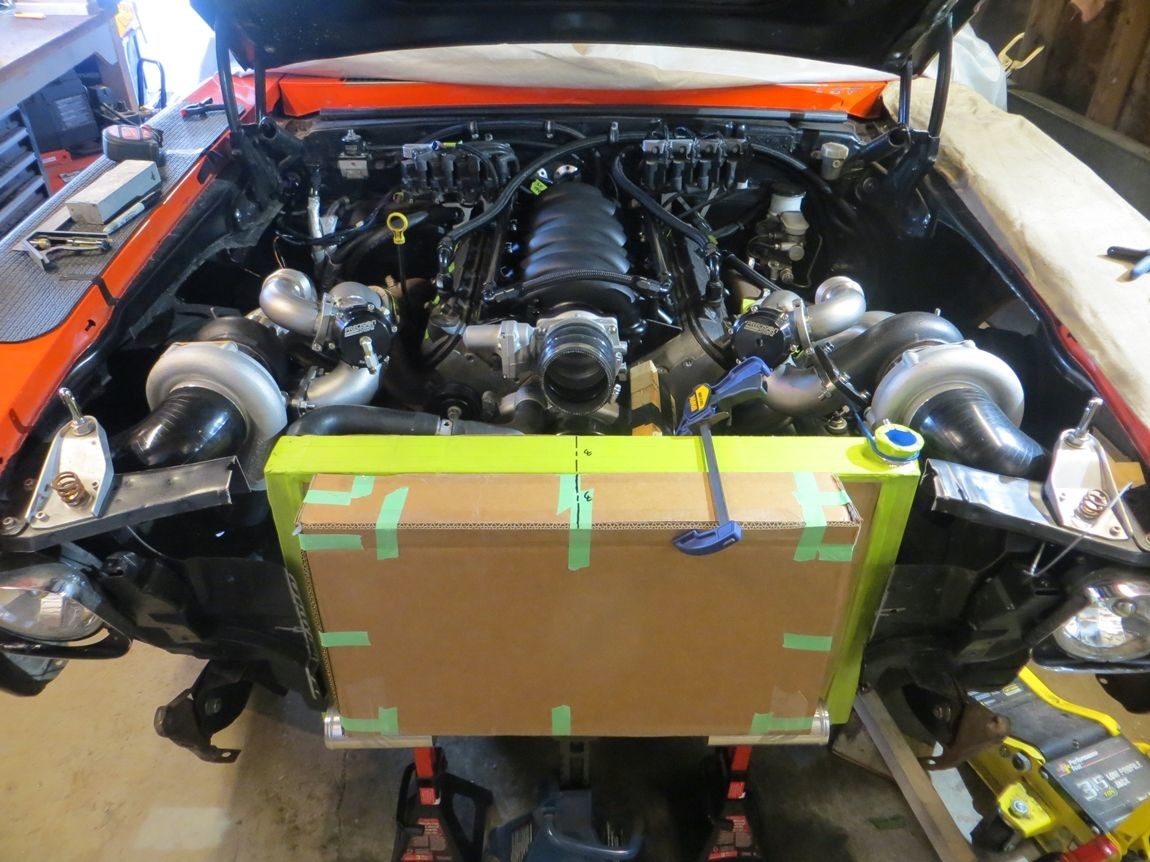
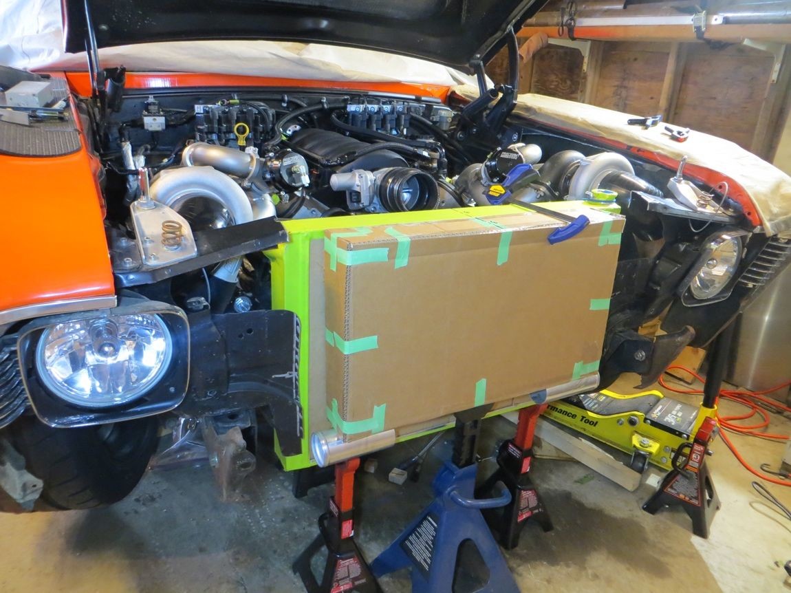
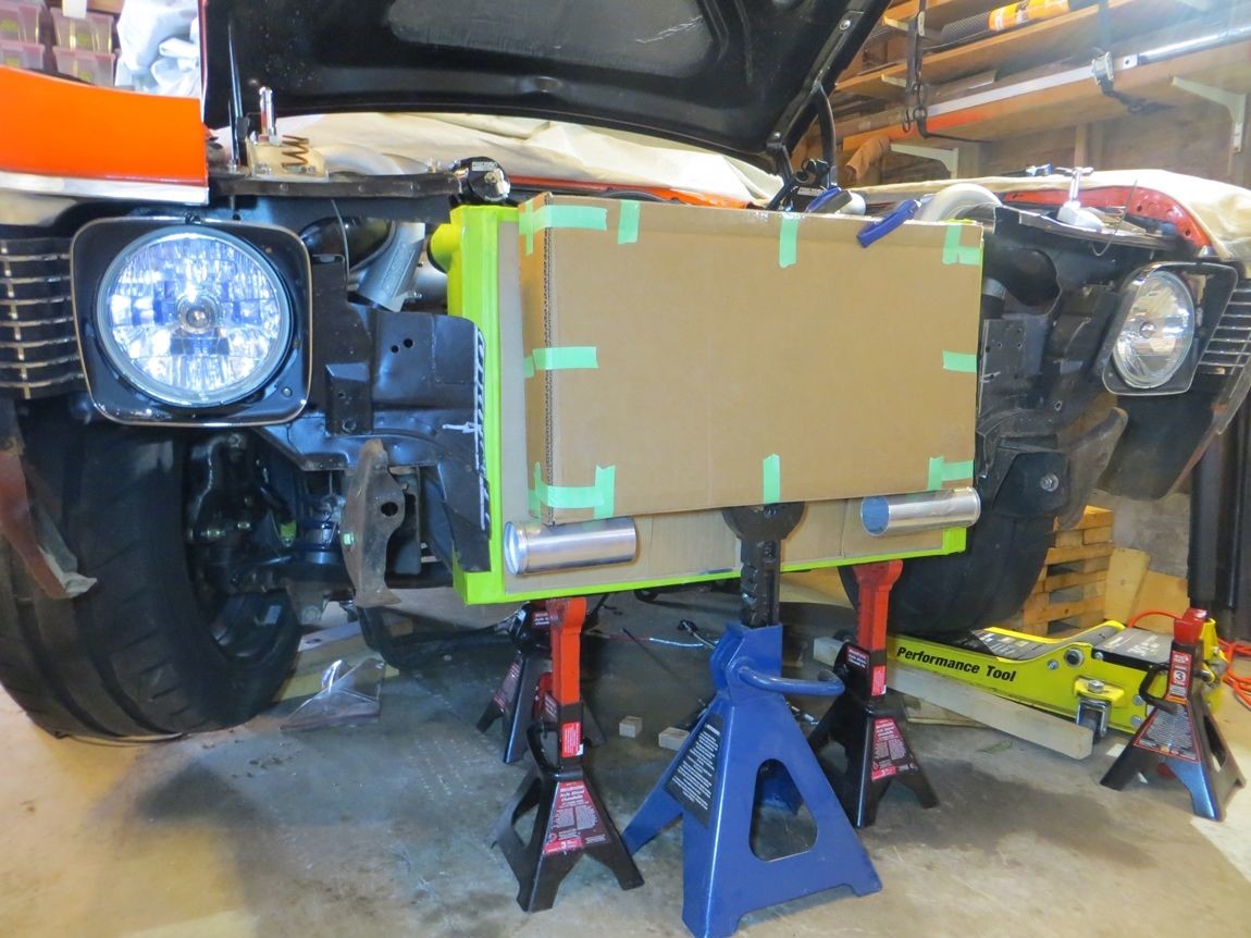
What the pair of cores will look like...
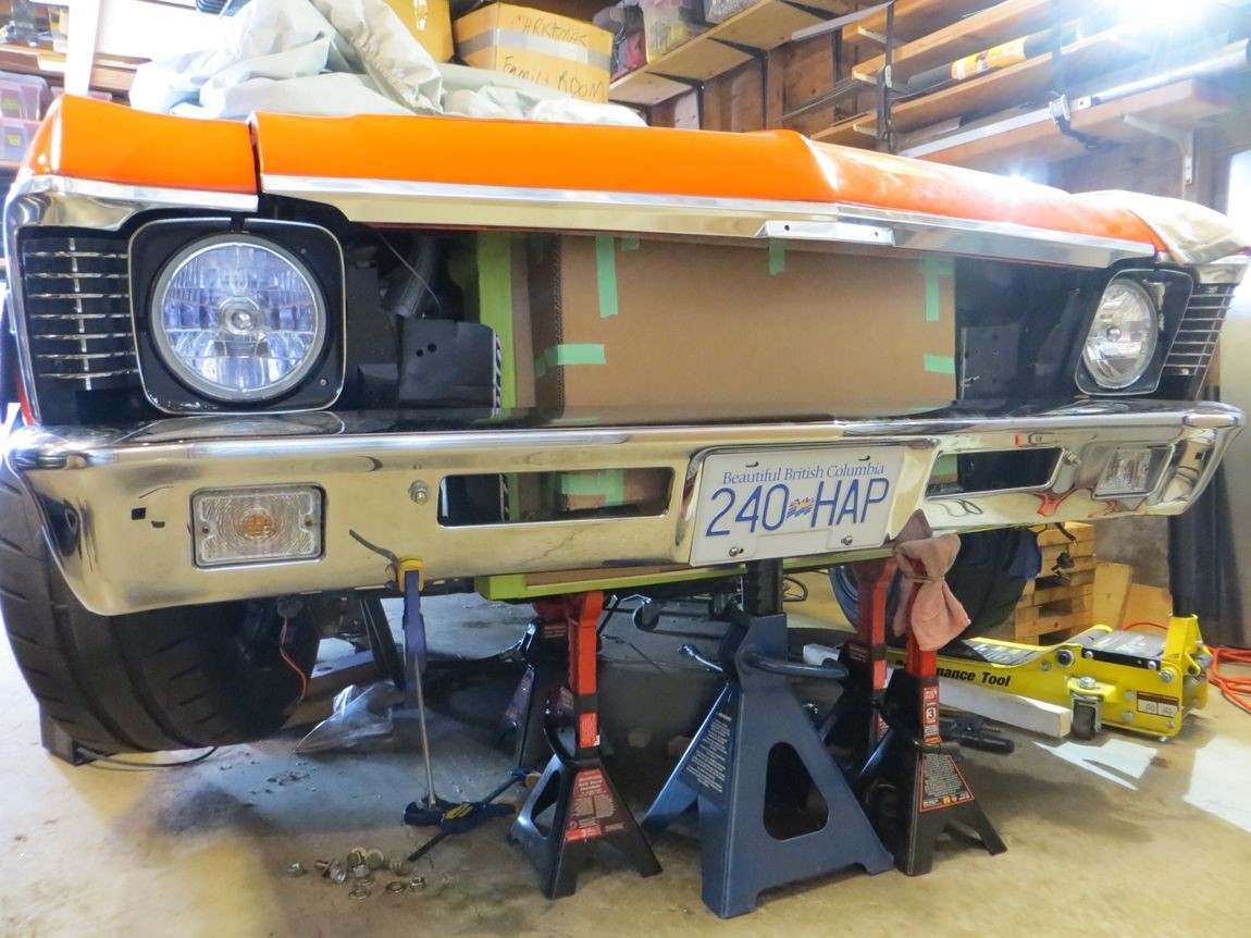
Of course, I didn't want to risk damaging the cores even with cardboard protection, so I made a cardboard mockup intercooler with the same dimensions..
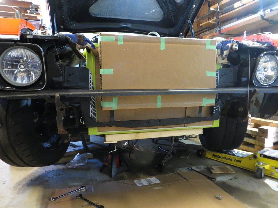
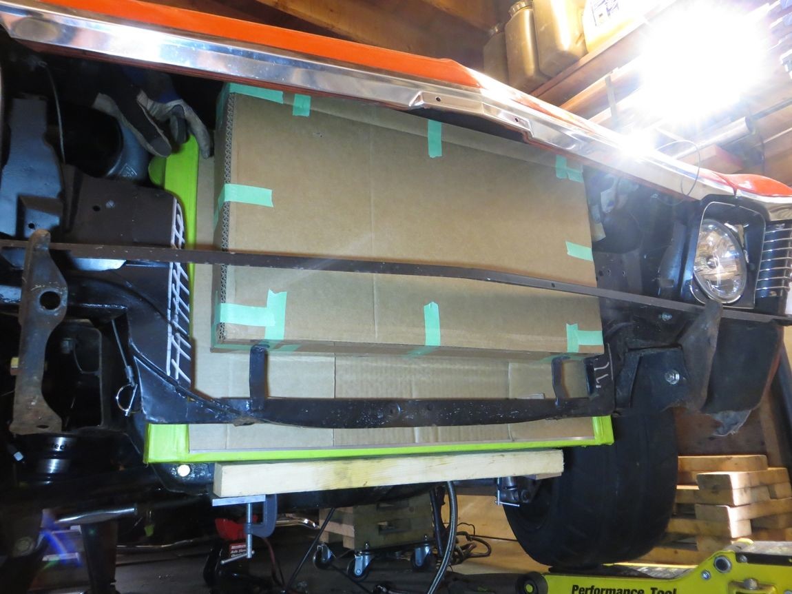
Of course, time to hack out even more of the rad support.. the last thin piece linking the two rad support sides together. I'll make a custom frame linking it all back together once I finalize out the rad/intercooler placement.
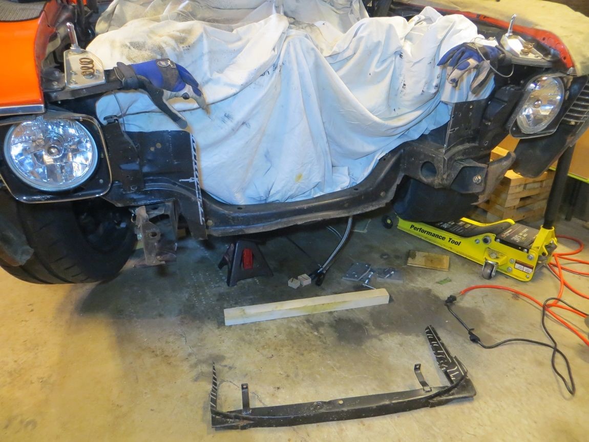
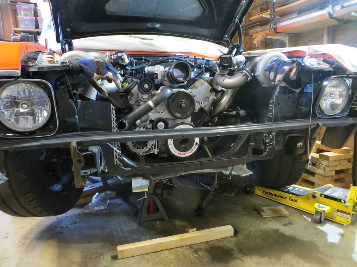
I'm going to trim the front of the subframe horns, and notch the bumper brackets to make room for the 2.5" charge piping to pass thru, so the piping can then take a 90* bend up on the outside of the subframe rails, into the turbos...
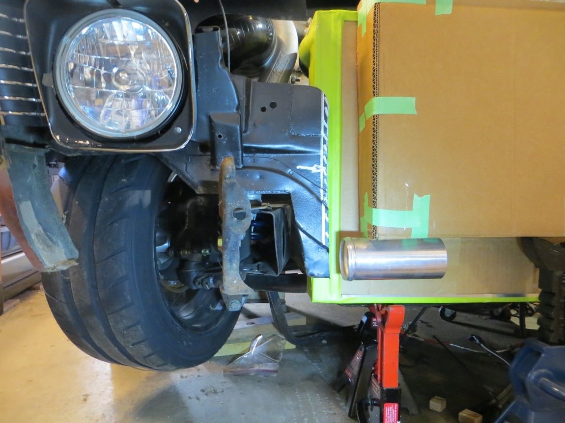
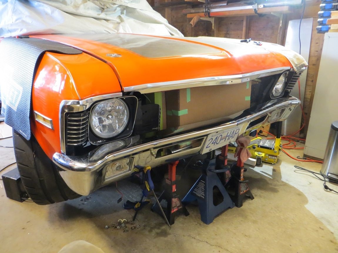
I was experimenting with what the bumper would look like "sleeker" tucked about 1" rearward and up 1/2".. it's okay but a bit cramped... I think when I modify the bumper brackets I'll leave the bumper in the stock location.
****, that's my bad Andrew... I even knew that was your name but I was replying to your post as I read it, and saw Adam so typed Adam haha.
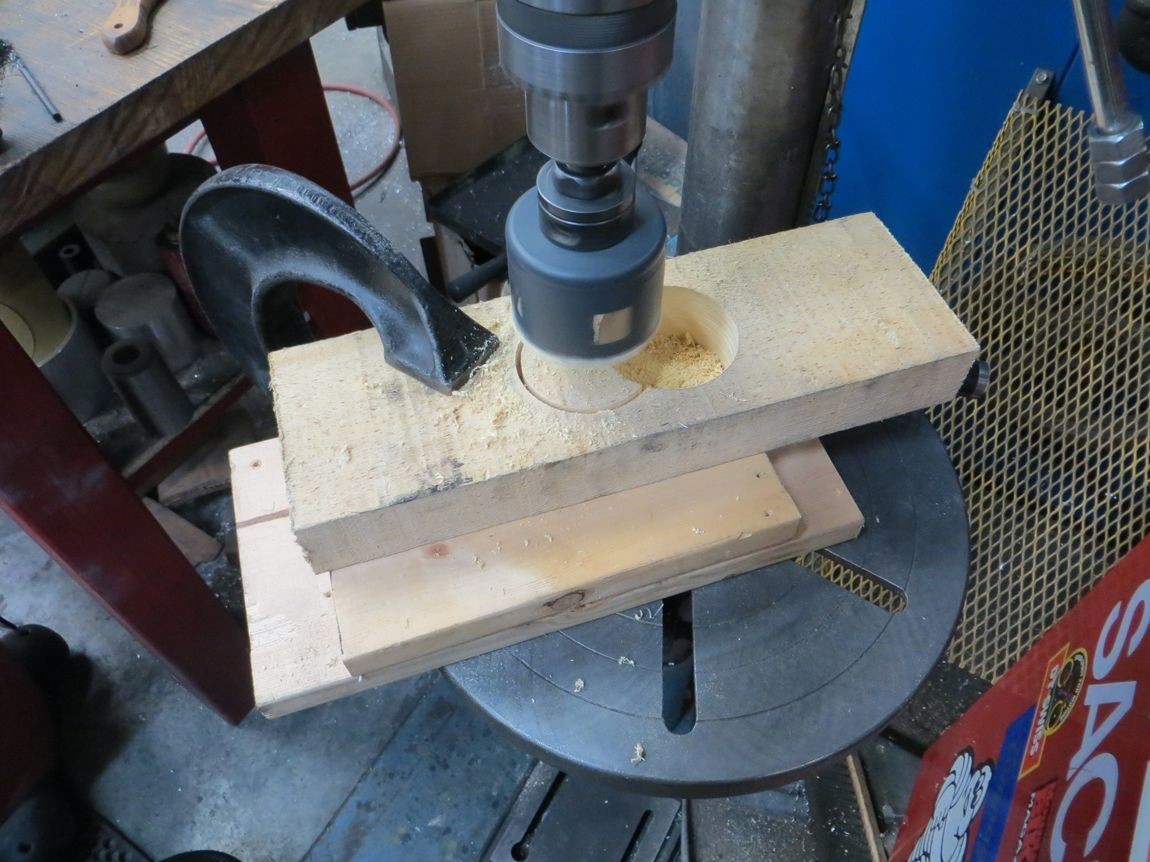
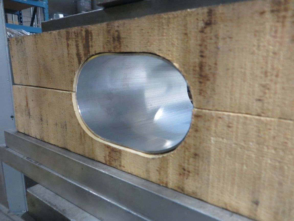
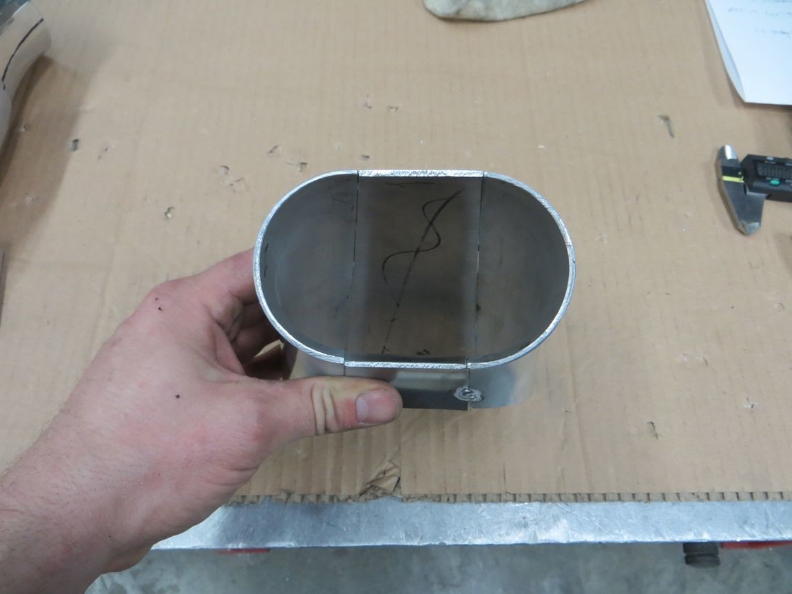
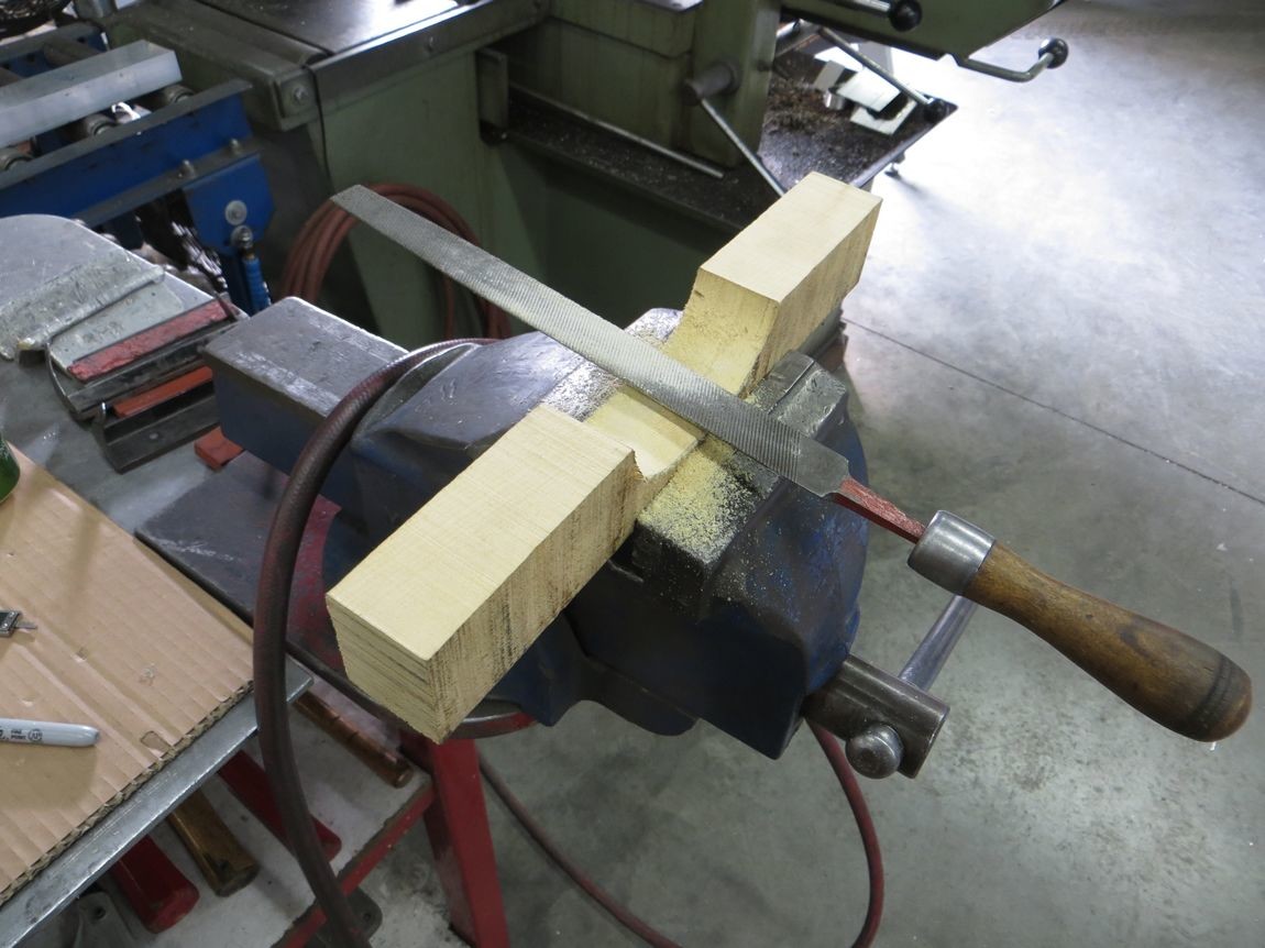
Started on a couple different intercooler things today, including trying to ovalize tubing to give the outlet charge pipe more clearance over the radiator. So I made some tooling!
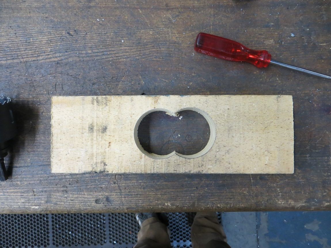
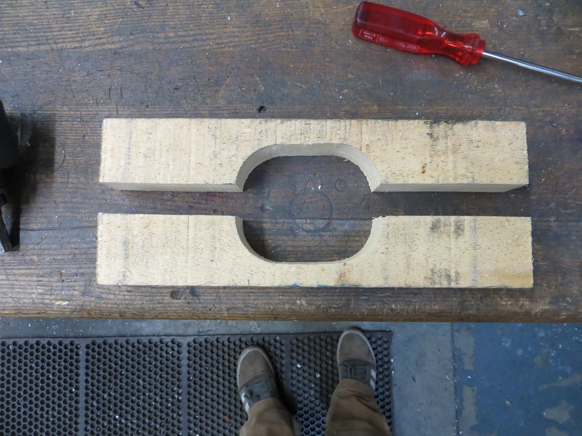
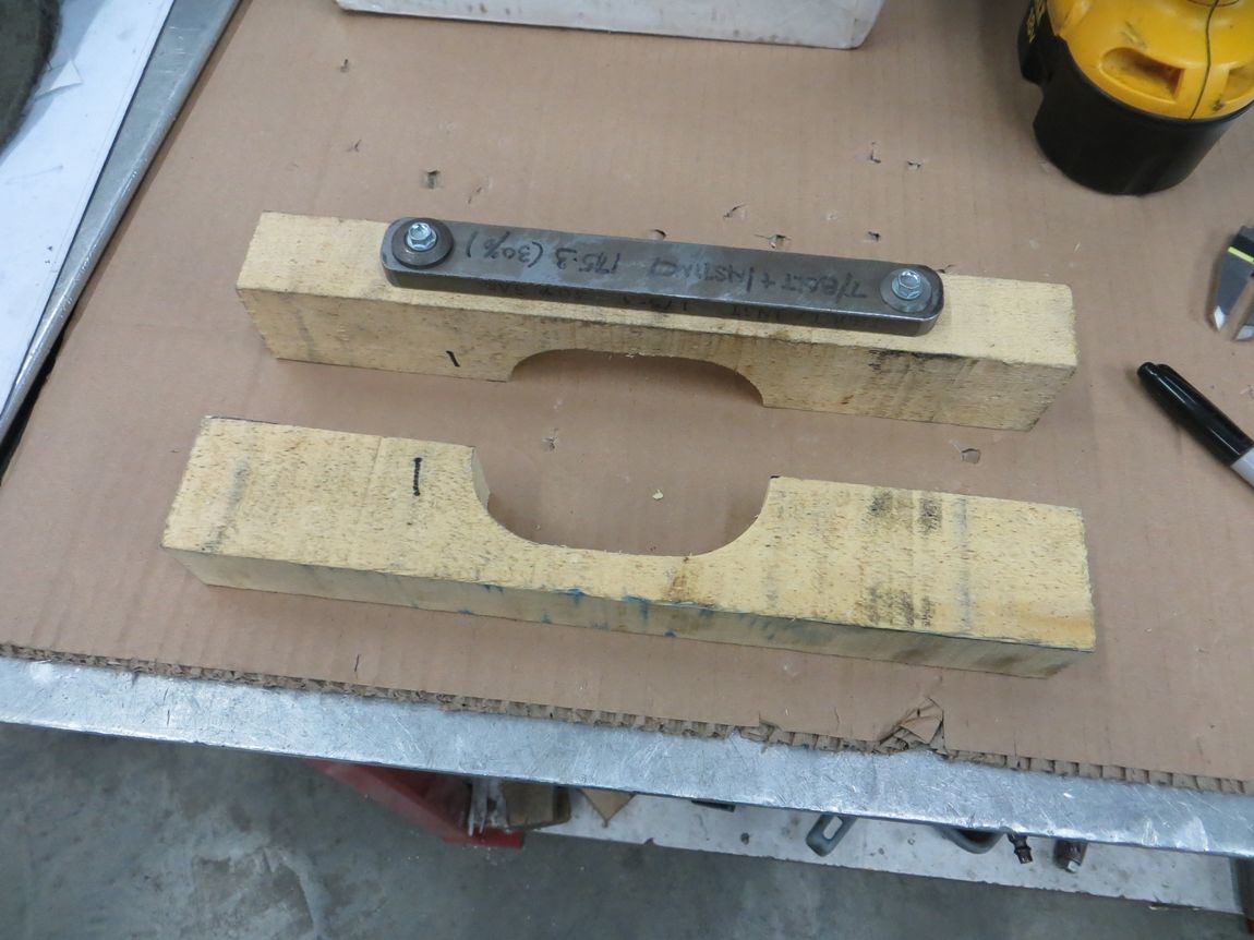
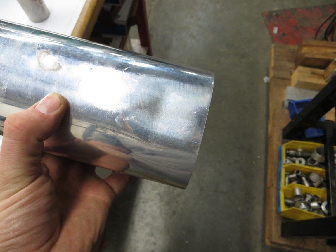
Worked pretty well! This forms a 3.5" OD tube to 2.5"x4.1" oval.
I anticipated that this first attempt with no taper to the tooling might end up kinking the tubing somewhat, but wanted to try anyways. It's noticeable, but not too bad.. however I still massage the form and added some taper to it to prevent any kinks the next time around..
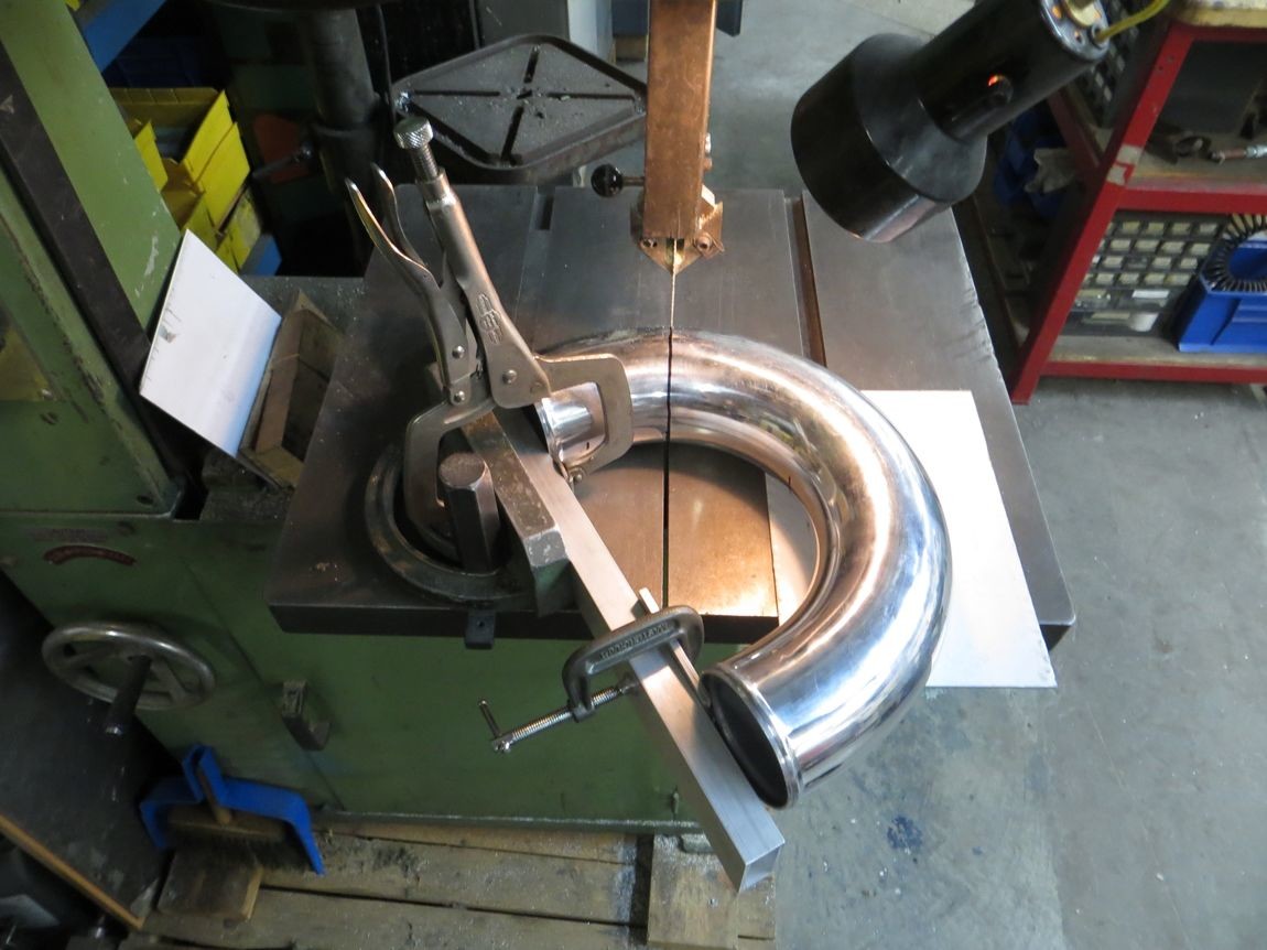
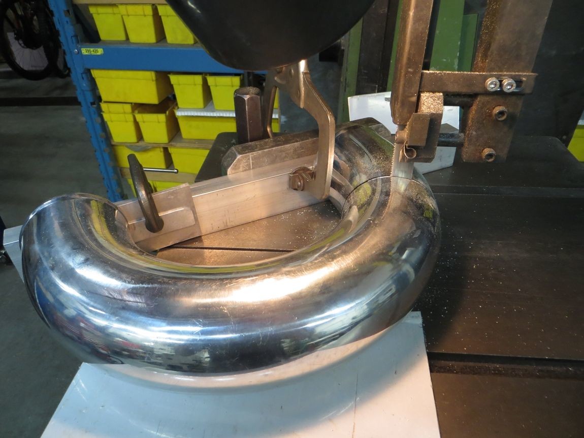
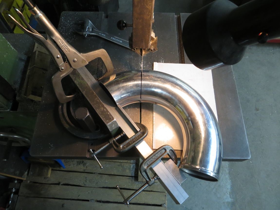
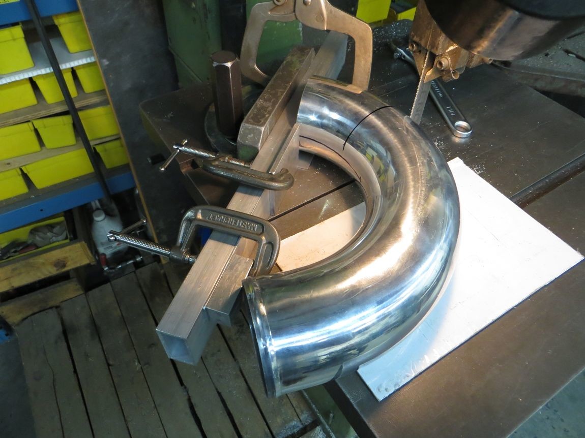
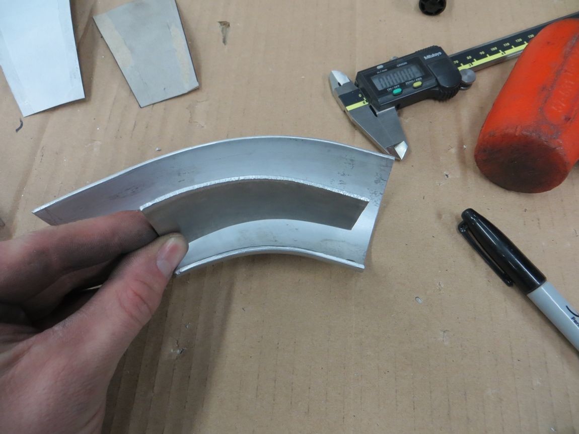
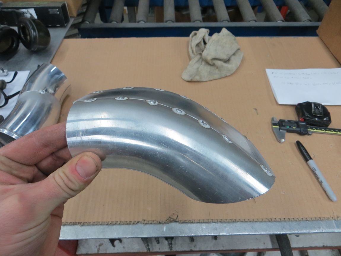
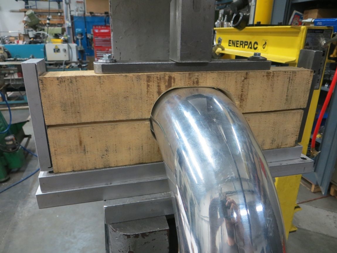
Next up was to start putting some shape into the 3.5" round pipe sections of the charge pipe. Included some pics of how I cut the U bend, can never have too secure of a fixture setup!
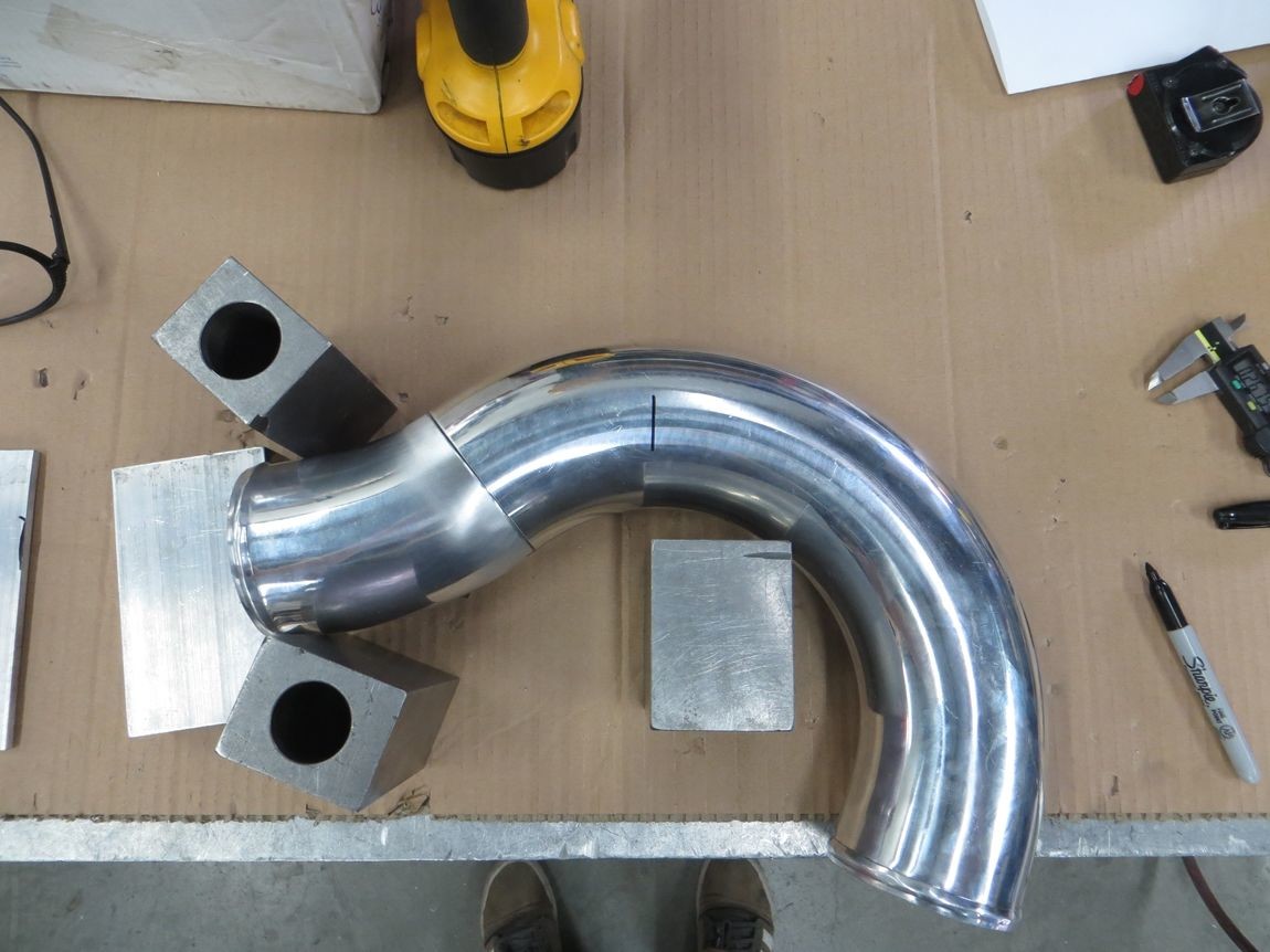
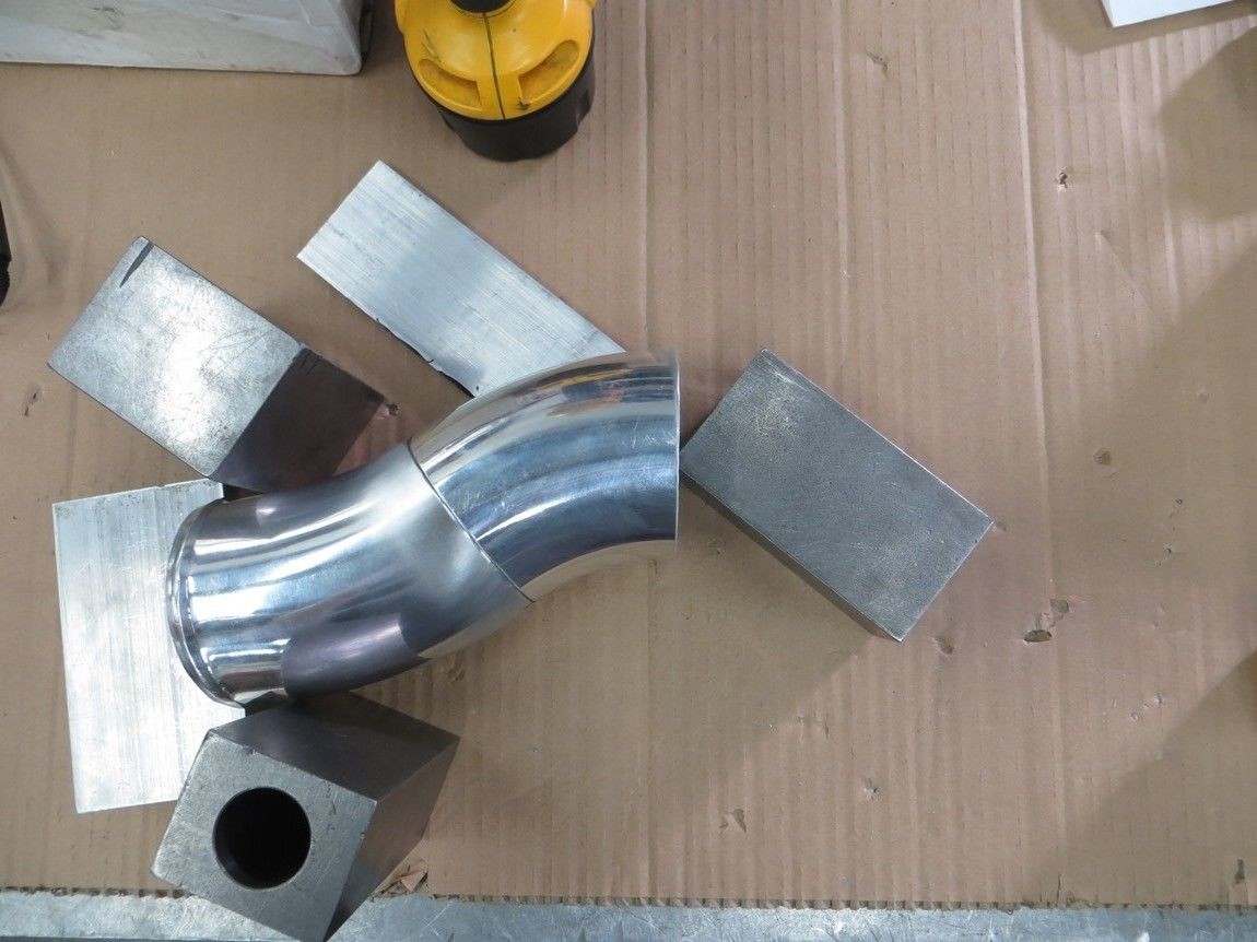
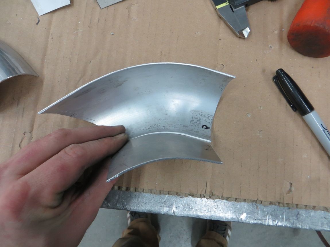
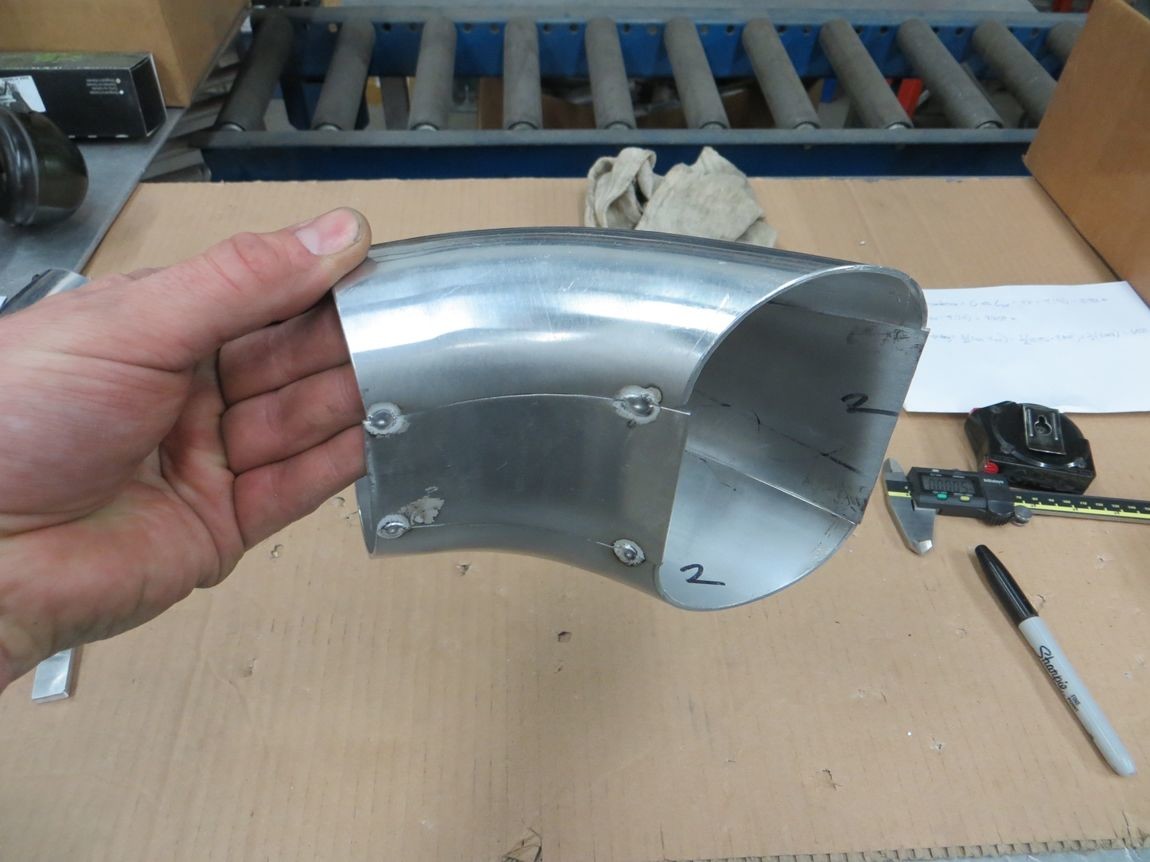
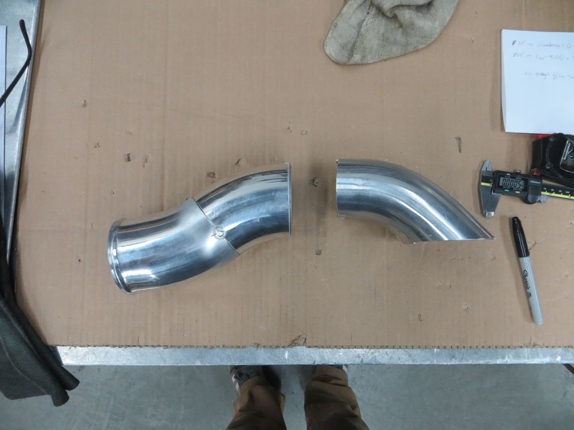
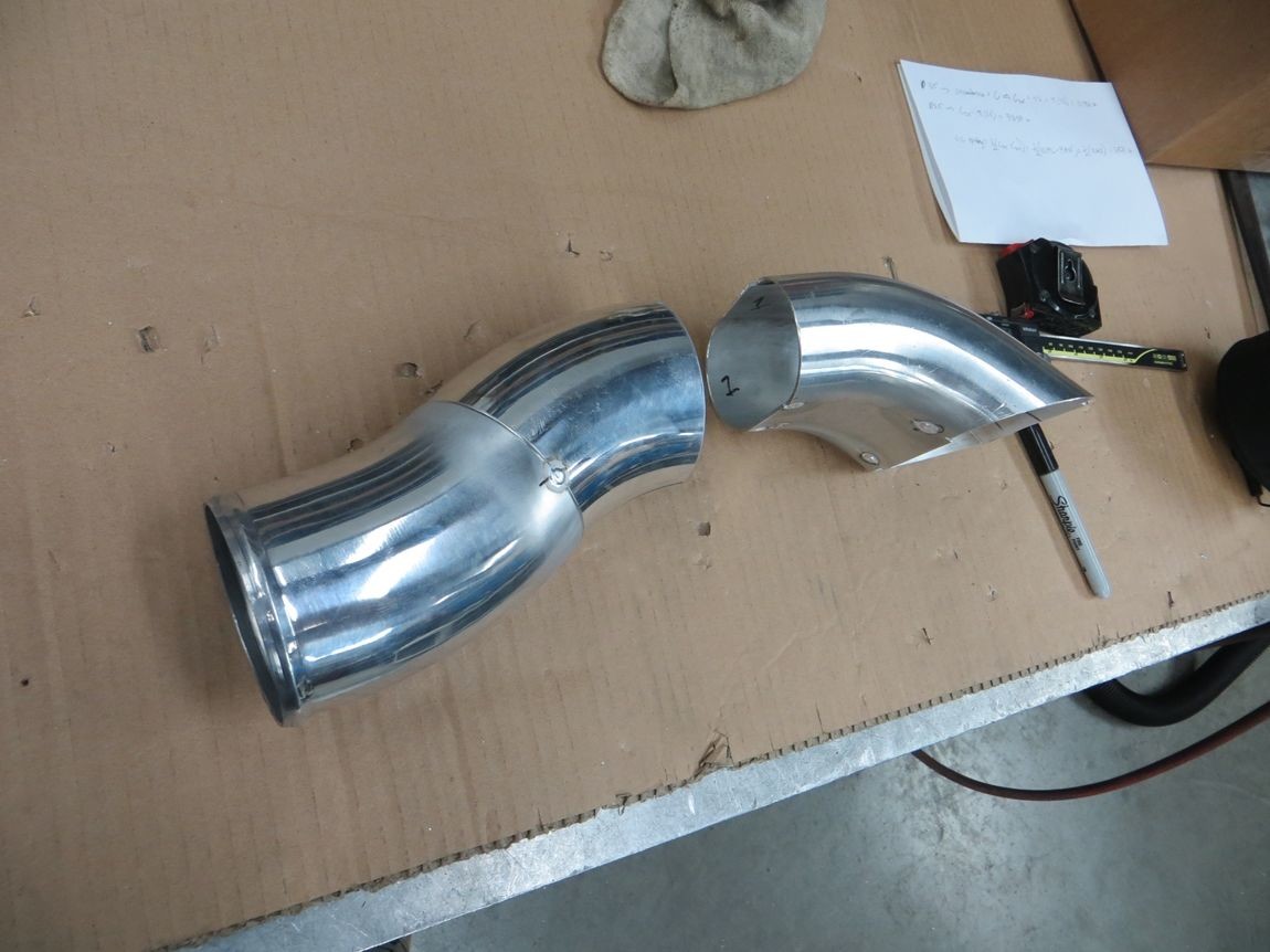
After staring at it for a while, I actually started liking my super basic first "mockup" oval elbow for the intercooler outlet that I made out of a split 2.5" slash cut bend and some cardboard filler. Decided to run with it and make it fully out of aluminum, to have as an option for the intercooler outlet..
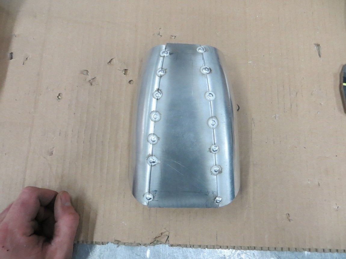
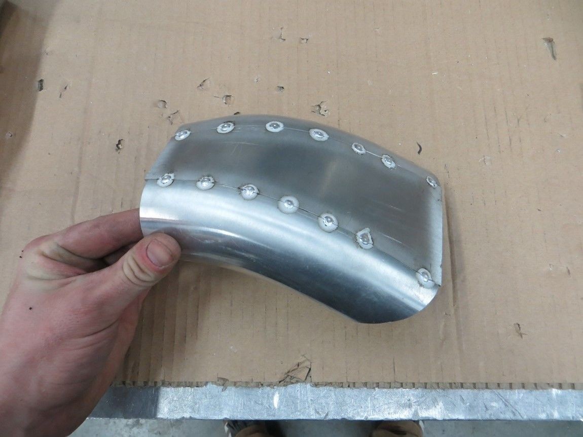
Now to just make a 3.5" round -> 2.5"x4" oval transition to link the two parts. The gap where the transition goes is directly over the radiator. I'll wait until I've finalized the radiator and intercooler locations before finishing this piece off with that transition. I'll probably end up pinching the tip of the S bend a bit just to make the transition less abrupt.
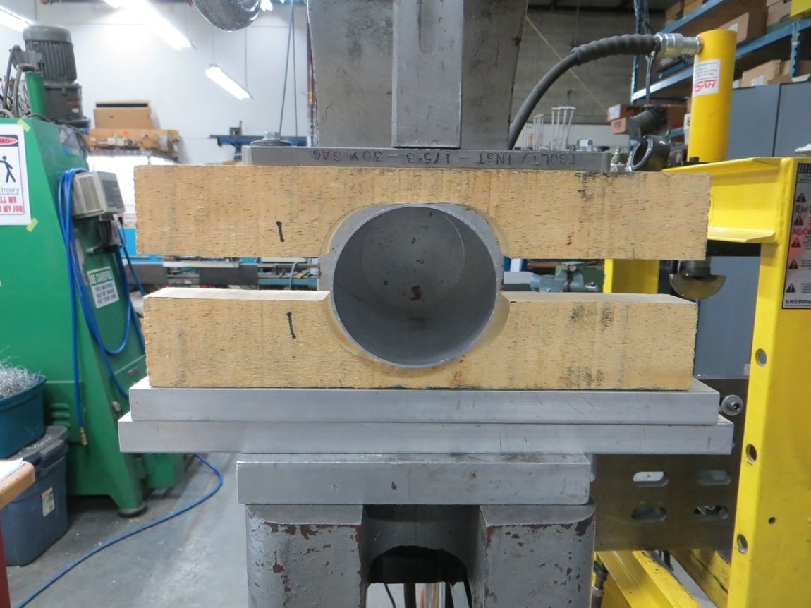
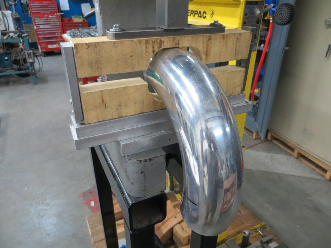
And just as an extra point of interest.. after doing all the above, I was curious to see how well the 3.5" mandrel bend would deal with some ovalizing forming, with the residual stresses in the tube from the bending process. Turns out, it doesn't like to be formed again.
Did some manual smoothing/tapering of the wooden form to help the situation with less kinking...
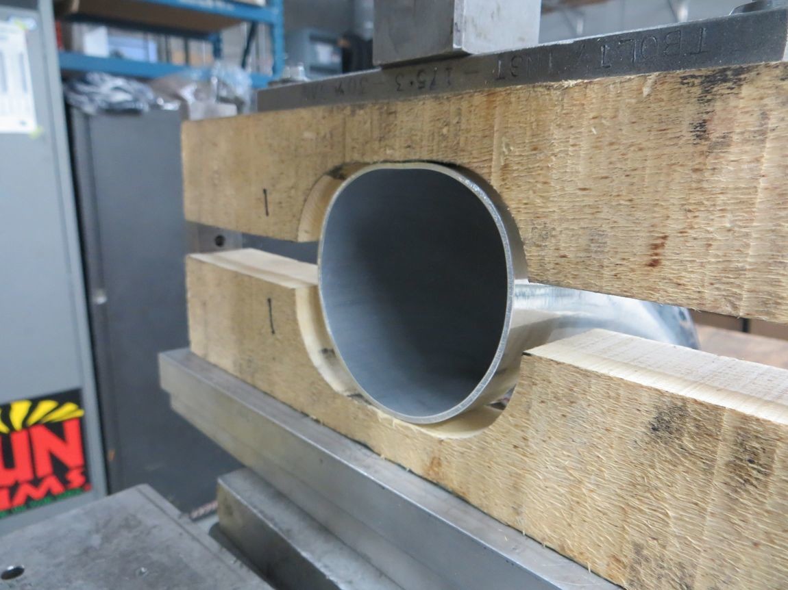
Initial setup before any compression...
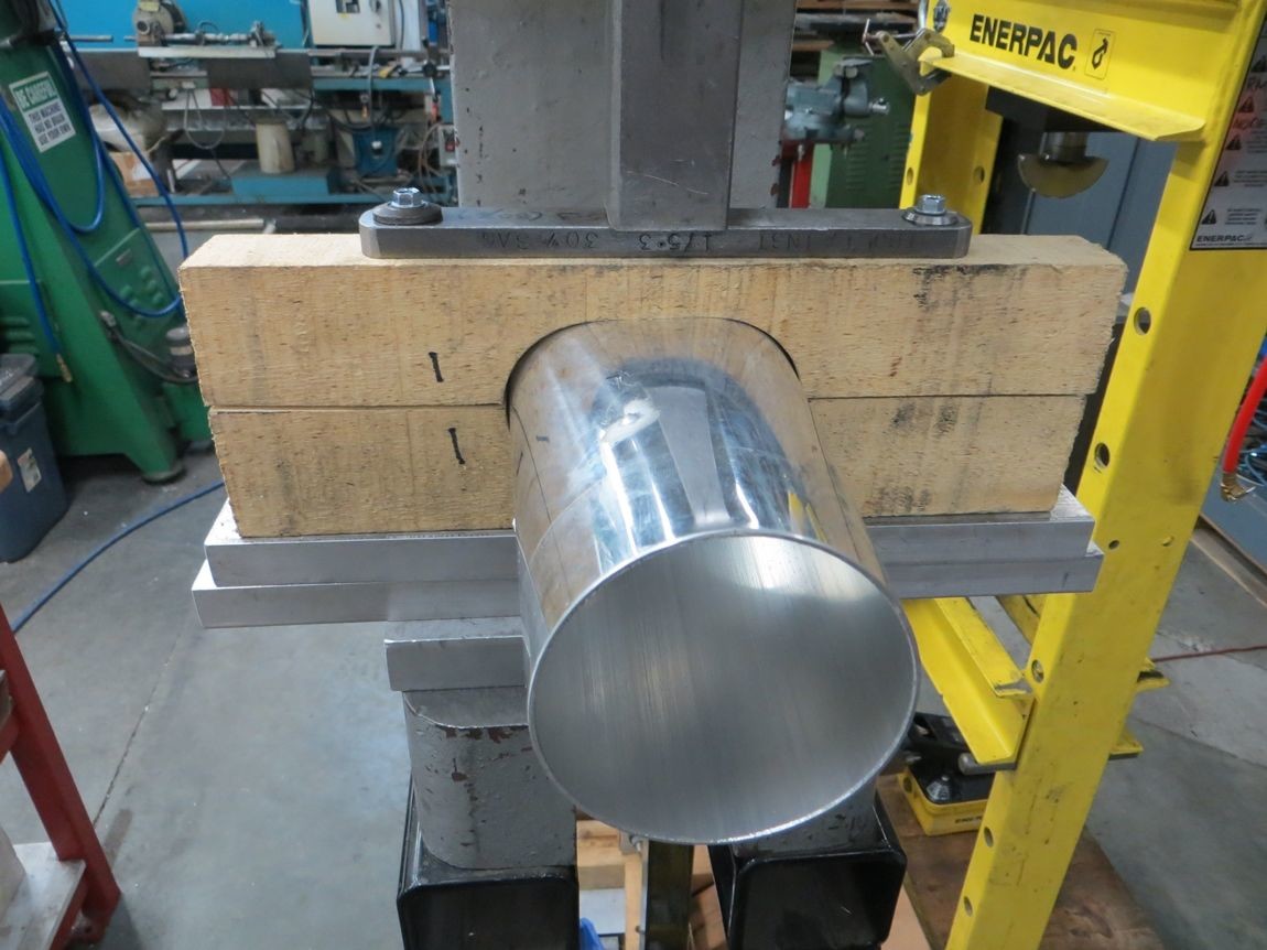
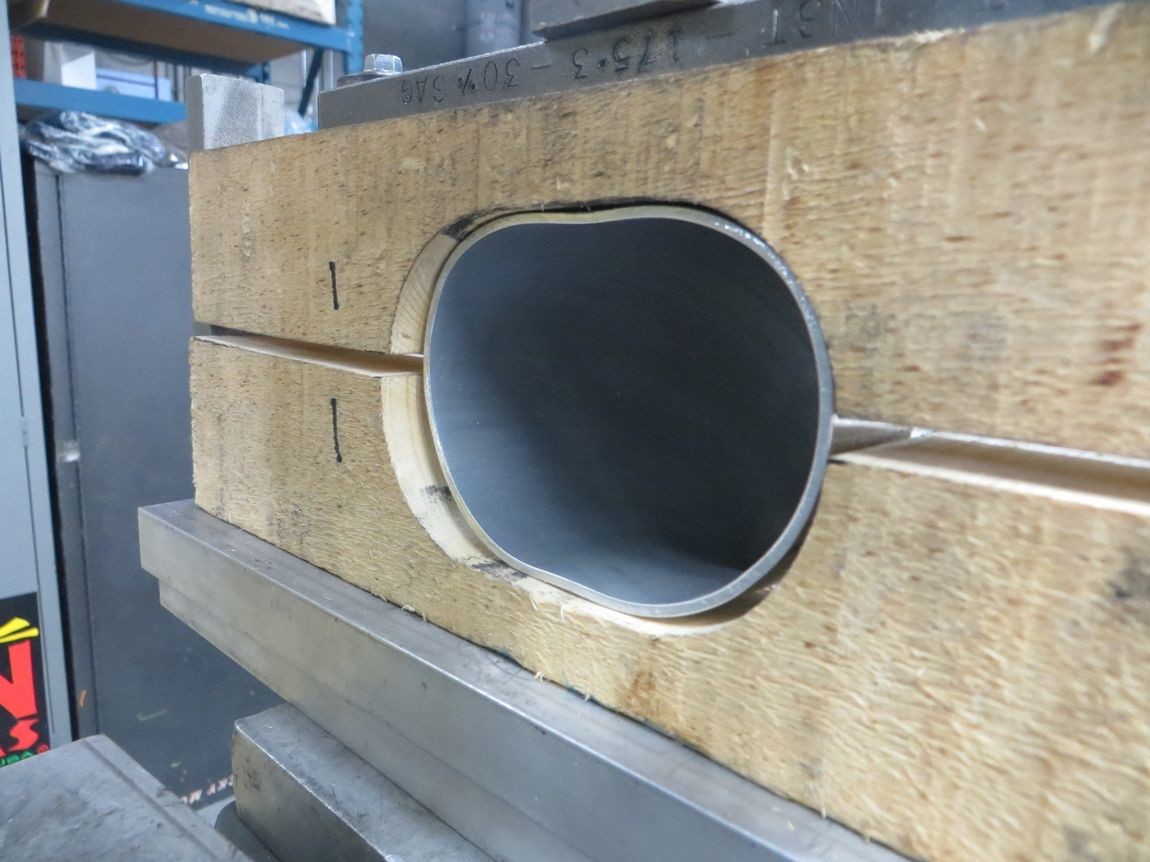
This is with about a 1/2" of compression, you can already see the outside wall of the bend wants to collapse seeing as it's already experienced a lot of tension/stretching from the mandrel bending process...
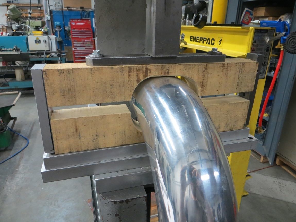
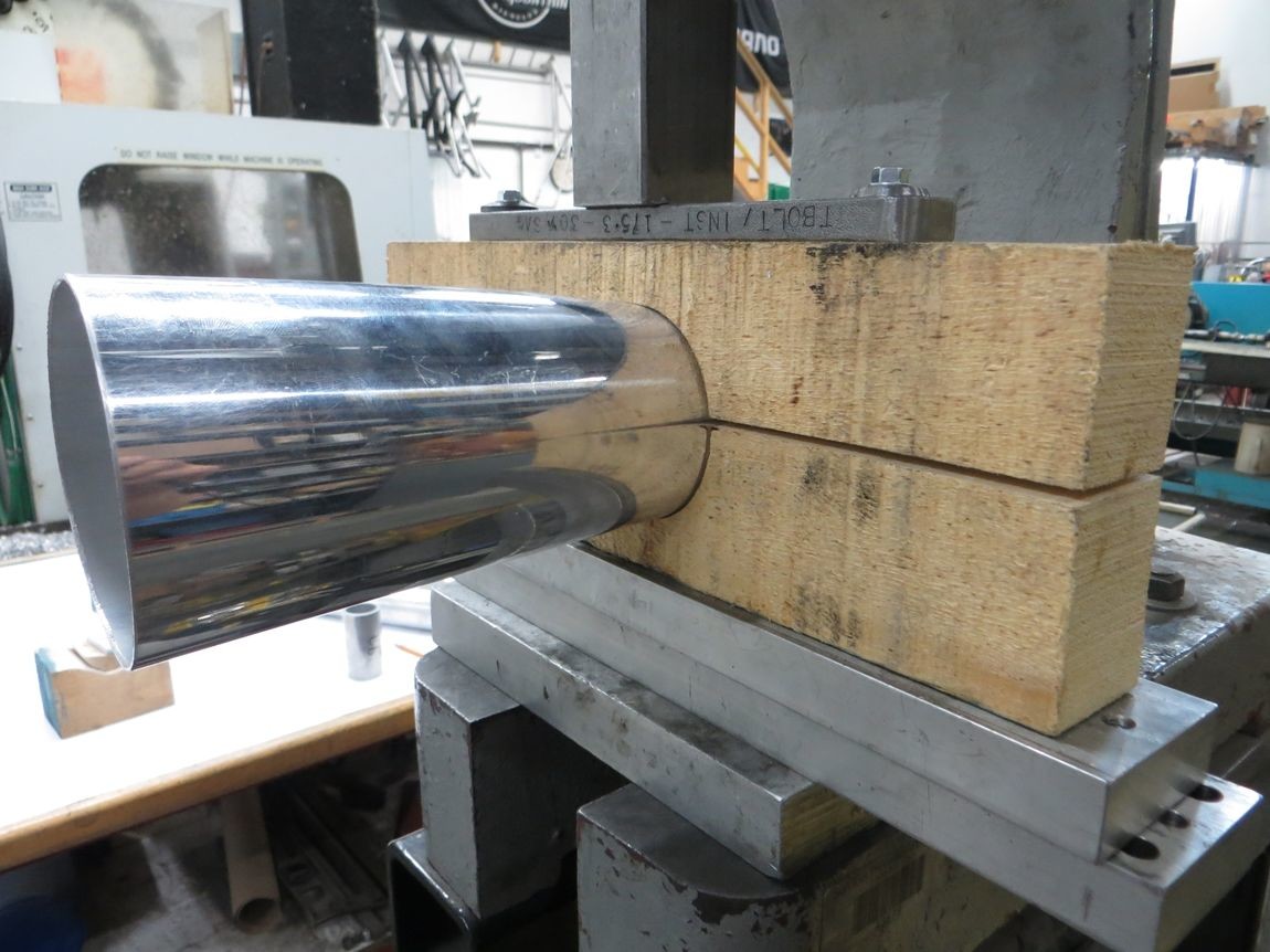
And this it after full compression AKA wood form bottoming out on itself, there's a good 1/4" of spring back and you can see how the corners of the form didn't want to get "filled out" by the tube, and there's more kinking and deformation on the outer side of the bend...

Wow thanks for sharing!
Posted by Diggymart on 3/3/19 @ 12:40:25 AM