You must be logged in to rate content!
10 minute(s) of a 891 minute read
7-9-2020
Got some good progress this weekend, which felt nice since I've been busy with vacationing the previous 3 weeks.
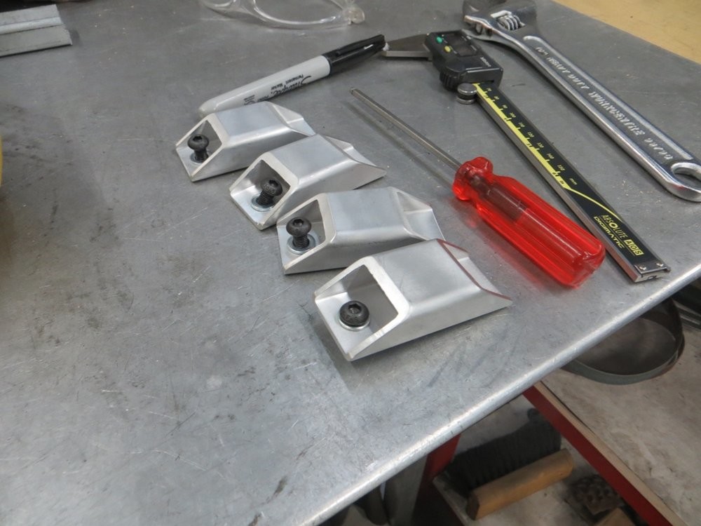
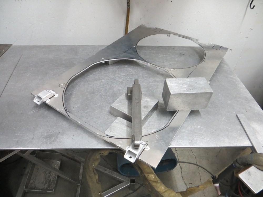
Made some threaded bosses and mounting tabs for the rad shroud, so I could make it all one self-contained unit to start mocking up the required rad support bracketry.
A little fixture to hold the threaded boss square..
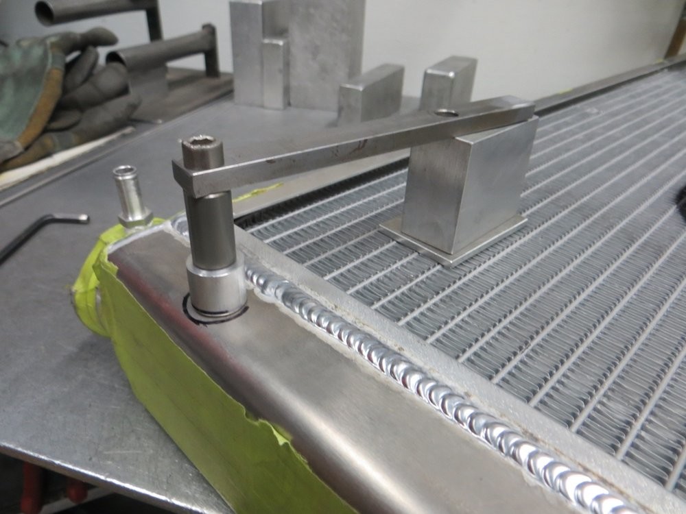
When the tanks are masking taped to prevent scratches, gotta get that welding ground somehow!...
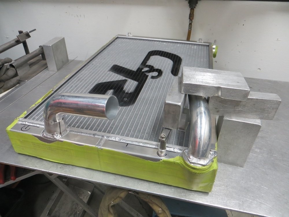
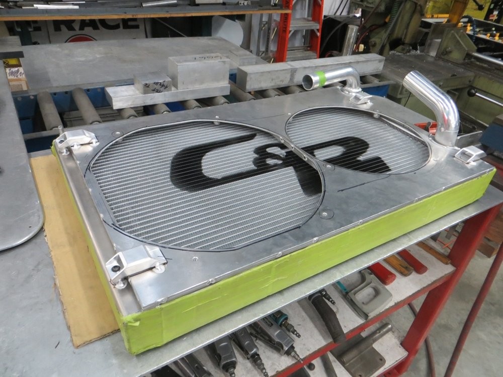
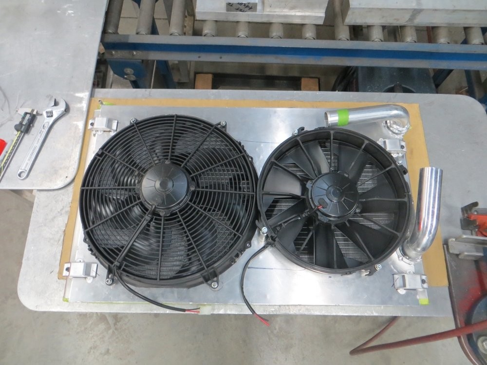
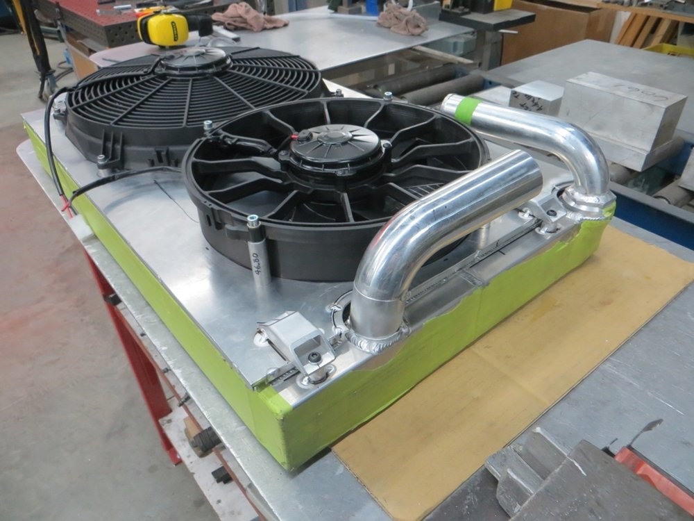
It's a [mock]-assembled unit! I'll be trimming the tube on the upper outlet as it's currently close to, but not touching, the 12" fan.
This update is some older progress, but groups together with my next update so I'm trying to be better and group like updates together, and not jump all over the place... for people that may be looking back thru the thread for reference, me included.
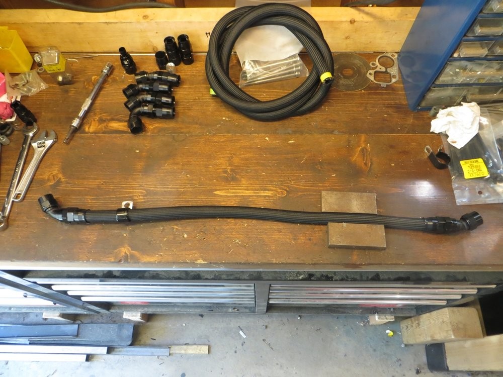
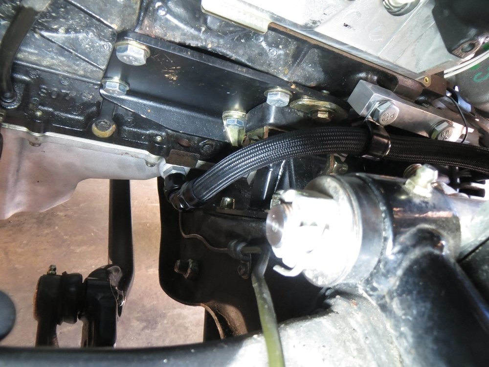
Here is the passenger side, because it was the easier side to start with haha. Because there's lots of room I just went full flex hose, and routed it smartly to ensure there isn't any rub.
It was such a good idea to simplify the passenger side motor mount pedestal with a minimal fabricated one, lots of room now to where the Holley turbo drain location is relative to the factory Nova mount locations.
Hard to take a pic of, but about an inch of clearance under the hose to the fabricated mount.
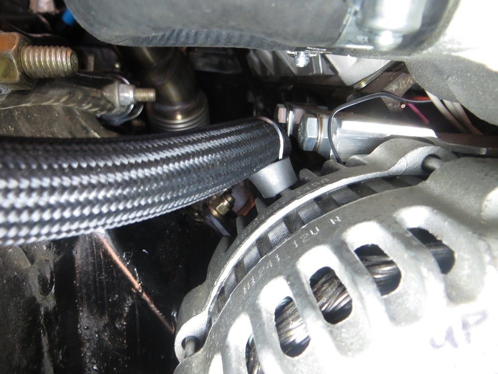
Used a vinyl-wrapped P clamp to tuck the hose close to the block (mounted to my alternator bracket) to ensure no flopping around. About a 1/4" clearance to the forward alternator bracket bolt, but requires some force to flex the hose over to touch the bolt head.
Used the good 'ol rubber hose standoff and ziptie to secure the hose to the alternator casing, so the hose doesn't rub the alternator.
And finished the hose off with a 30* -10AN hose end to the turbo drain fitting, just to help direct the hose closer to the engine as soon after the turbo as possible.
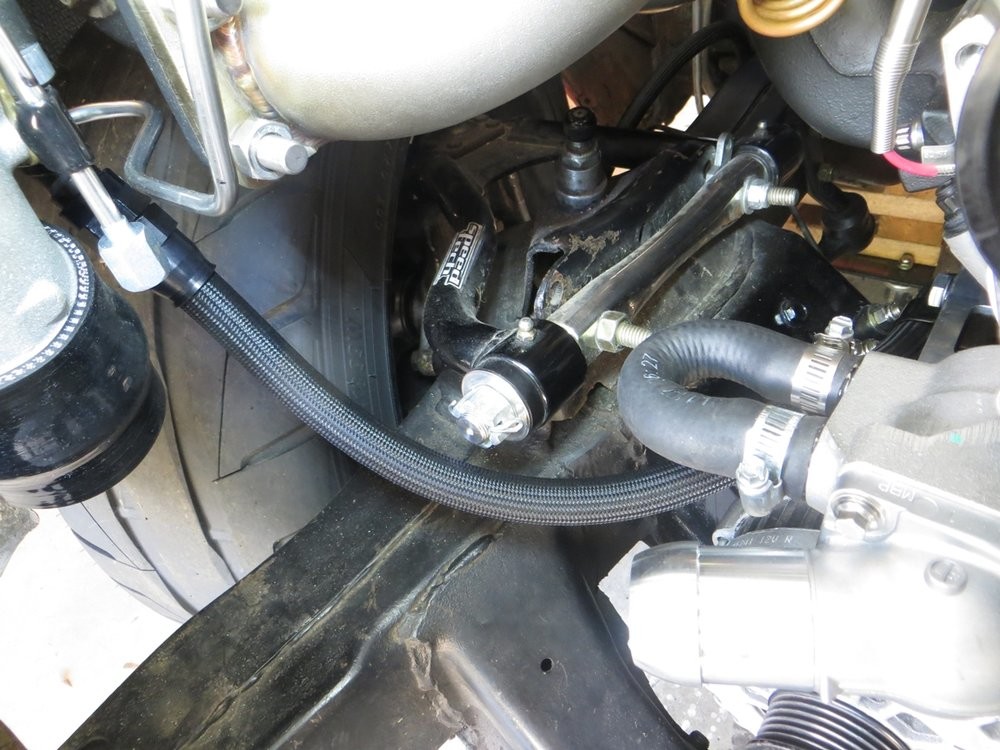
With the number of constraints on the hose, it can jiggle but requires a lot of movement in order to barely touch the UCA cross shaft castle nut, so I'm satisfied it'll be fine.
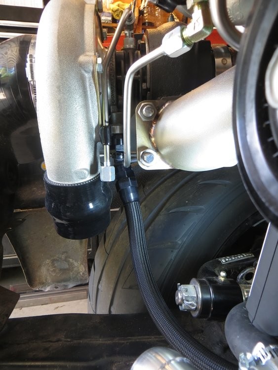
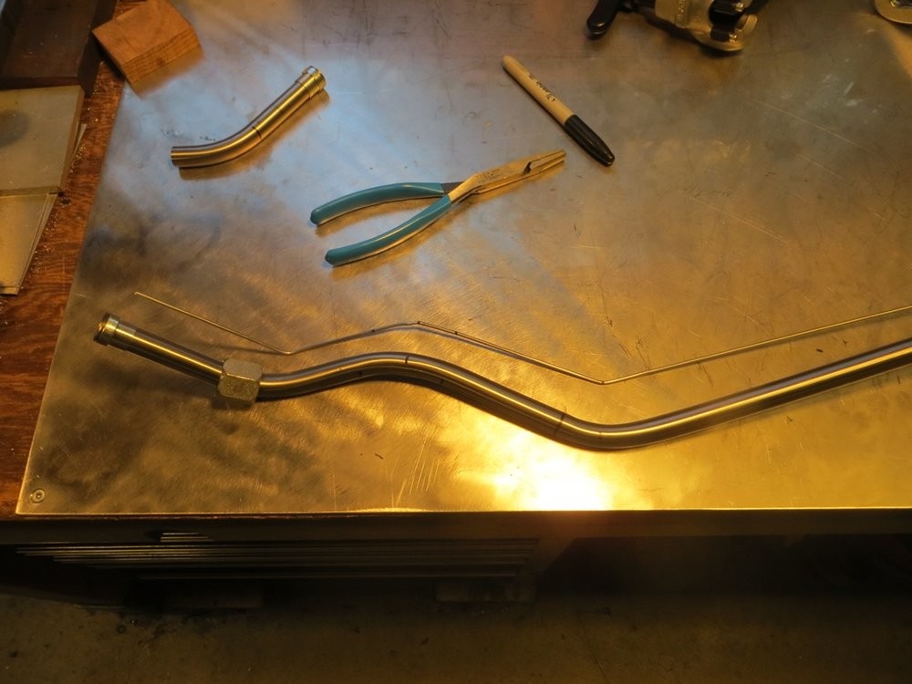
Because of the space constraints around the driver side downpipe, if I used hose it would naturally be a slightly bigger OD, but I would also want to heat sleeve it just to protect from the added heat around the downpipe, therefor this whole time I've been trying to make the driver side out of stainless tube.
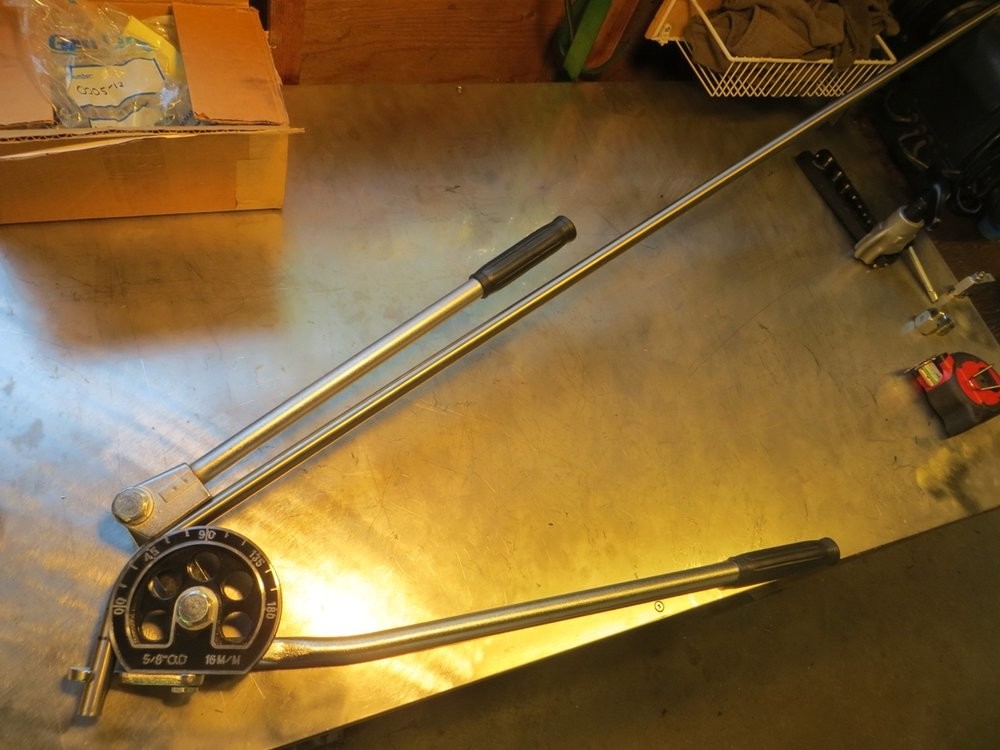
I ended up getting a $40 Amazon 5/8" bender since I couldn't find one locally, and figured at the very least that's cheap enough to justify the mandrels and I could make my own arms if they're weak and bend. Well guess what, the thin wall mild steel cheapy arms bend prettymuch right away...
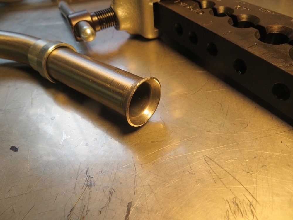
The bender worked long enough for me to make a couple preliminary bends, and I also tried out the Rigid 377 flaring tool on one end. Holy crap.. this thing works AMAZINGLY well.
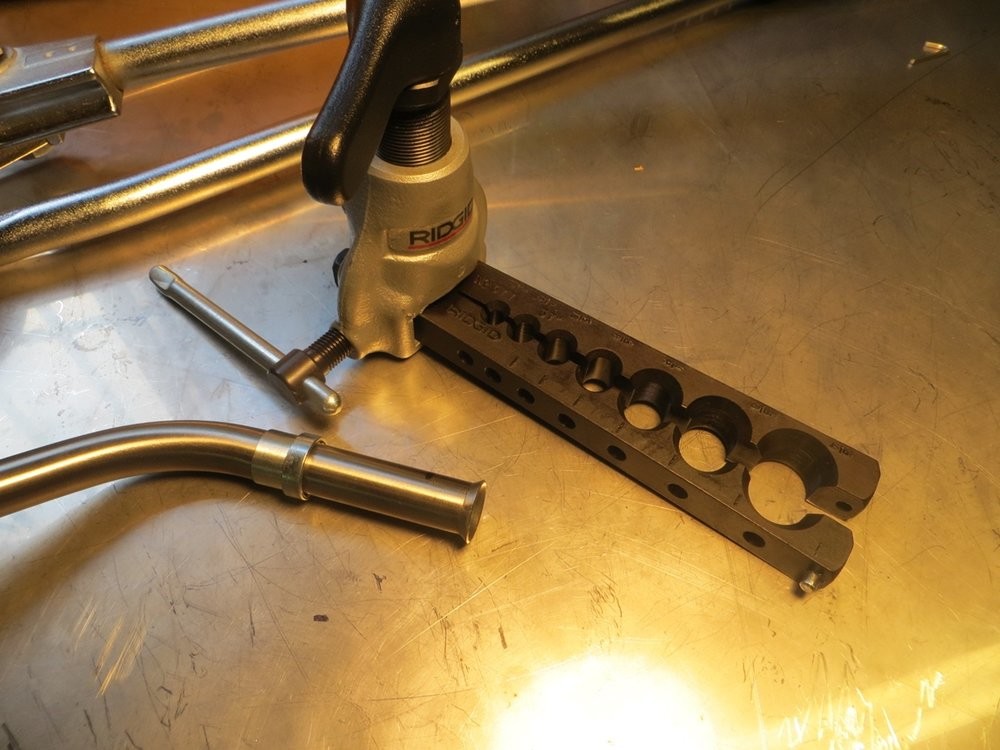
So easy, creates a nice smooth rolled surface, and I really like the tapered spring loaded pop-off pin once you've fully flared, to prevent over tightening and breaking the tool.
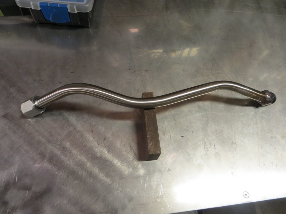
Since I needed to make a handful more bends (potentially) I decided to beef up the bender. I slammed a solid 3/4" bar stub into the drawing mandrel, fillet welded it, rosette welded it, then added a brace. I also drilled a steel block to act as the base to then put in my vice. I left the main handle as a stub so that I could throw a cheater bar on it when needed, but when not in use it's small enough to fit in my 37" tool box.
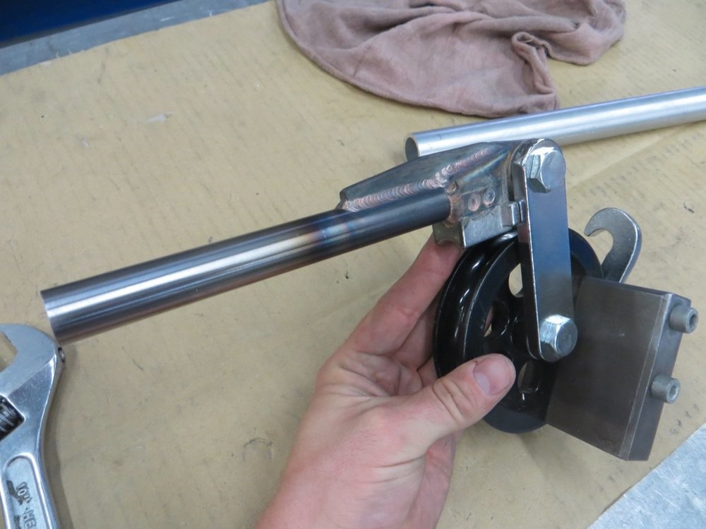
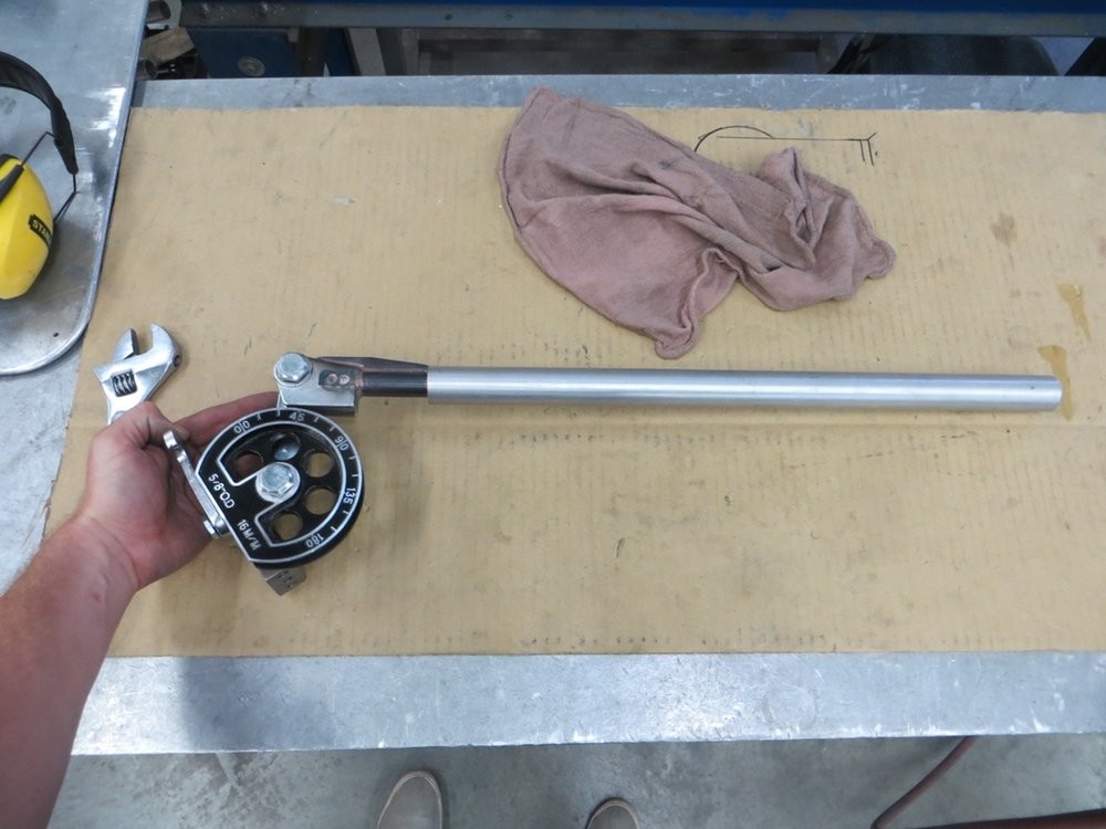
Works like a charm now!
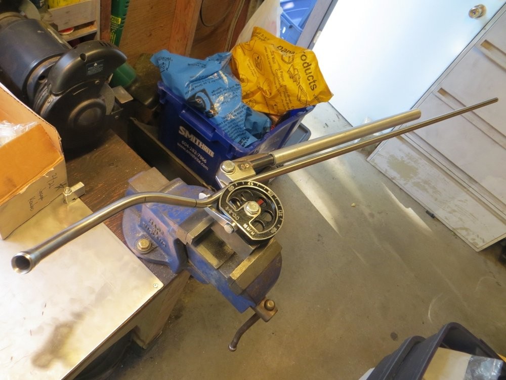
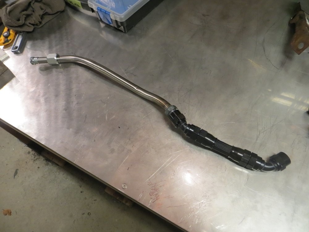
I was originally attempting to make it a single bend from the pan to the turbo, but given how stiff it was, I decided to cut it short and introduce a flex joint at the turbo.
I just welded on a -10 JIC bung on one end for the flex joint.
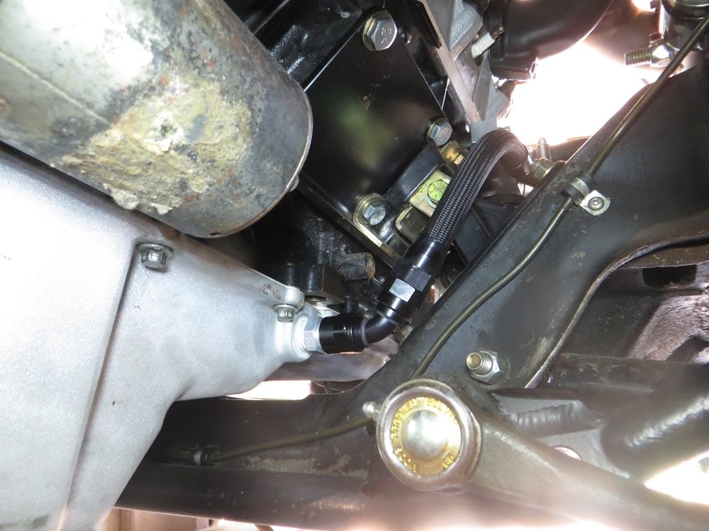
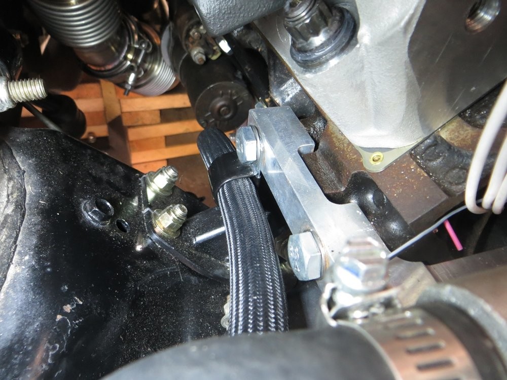
It kicks inboard right at the motor mount area just to give extra clearance to the downpipe in that area.
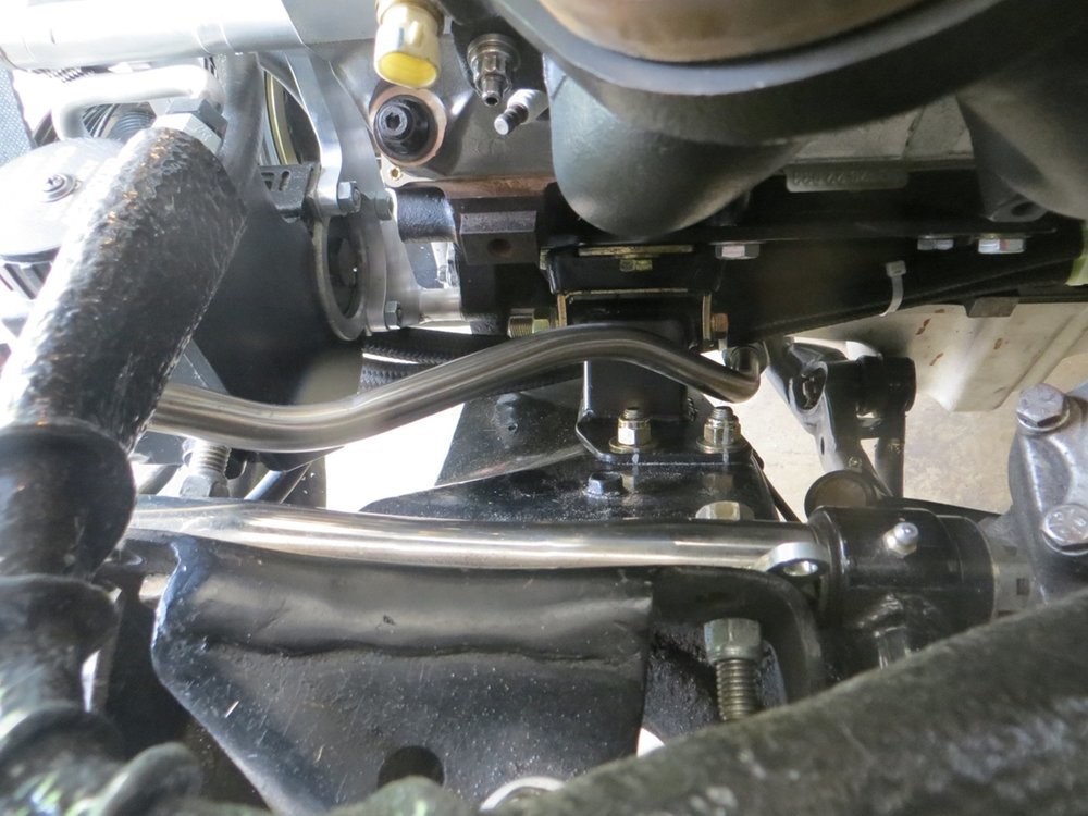
Within the perimeter of the factory mount pedestal bolt pattern.... way tighter to the block than wold have ever been possible if I used my modified OEM pedestals. I think I'm going to make a little metal strap support to bolt to the rusty M10 block thread shown, just to prevent the hard line from vibrating too much....
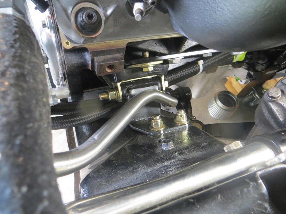
Flex joint is in an easily-accessed area....
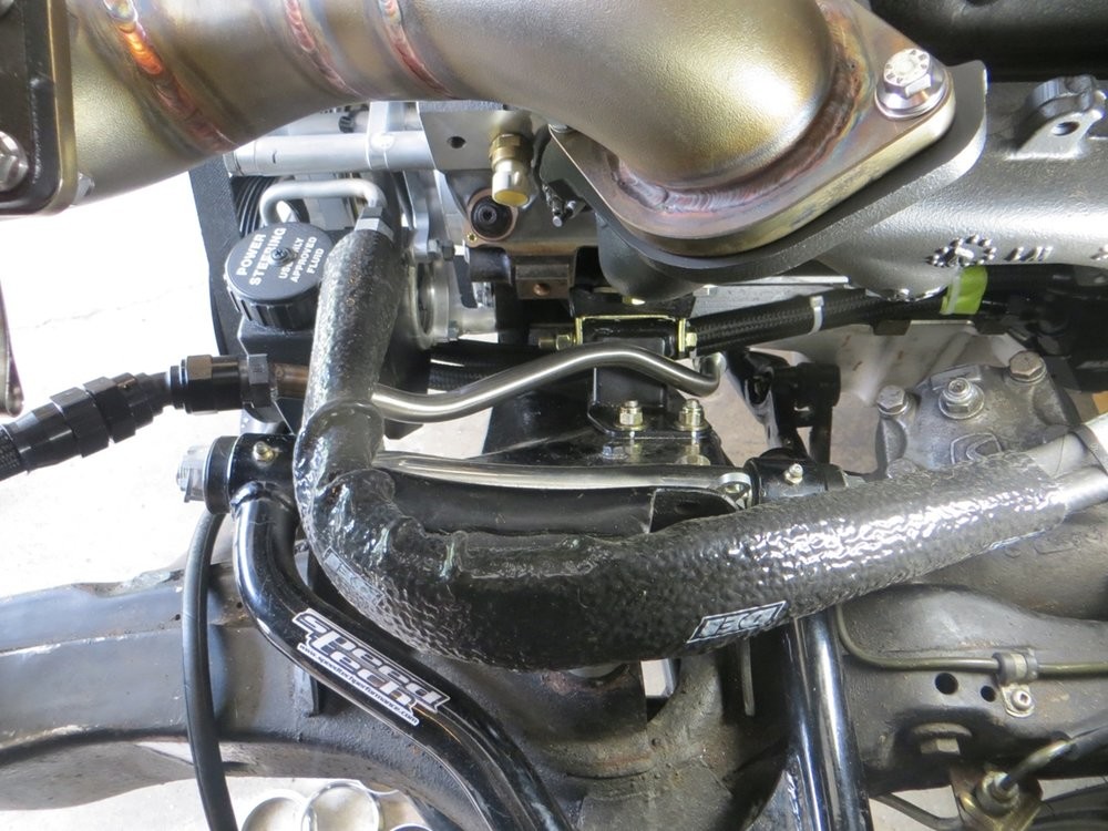
The stainless hard line is routed between the UCA mount bolt and the P/S lines. Since I used local hydraulic hose for the P/S lines, it ends up being fairly stiff once the orientation is set and the ends are tightened, so it's quite tough for the P/S lines to "bounce" up and down and possibly touch the turbo drain. Lots of room outboard of the turbo drain hard line to access the UCA bolt/nut with a wrench, should camber/caster shims been needed in the future for a less street-friendly alignment.
Constantly downwards slope the turbo to the oil pan...
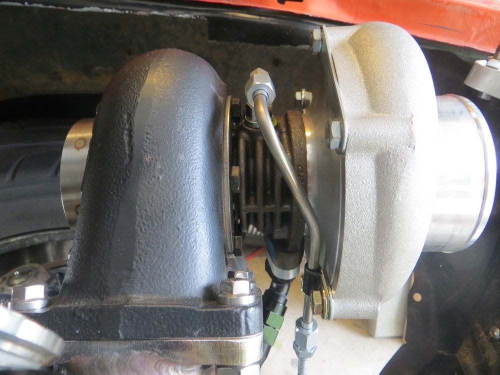
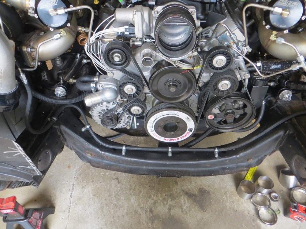
This is another update somewhat-long in the making, the turbo feed lines.
In keeping with the bent 1/4" stainless tube theme, I decided to make little "feeder" lines on the top of the turbos. This does a couple things:
a) keeps the lines as far from the turbine housing as possible
b) provides a hard point to then attach a forced-bend flex line between the turbo and the subframe (I'll explain later)
c) SYMMETRY!!!
To keep these hard lines routed tightly and firmly, I bent them so I could secure them to the compressor housing with a vinyl-cover P clamp...
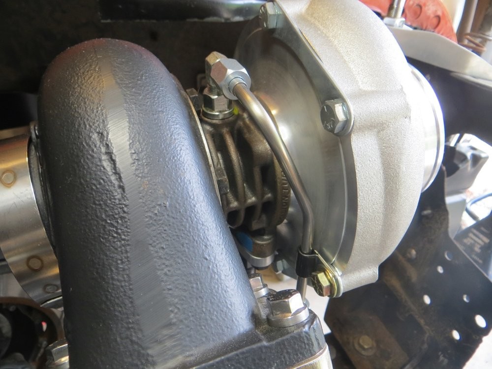
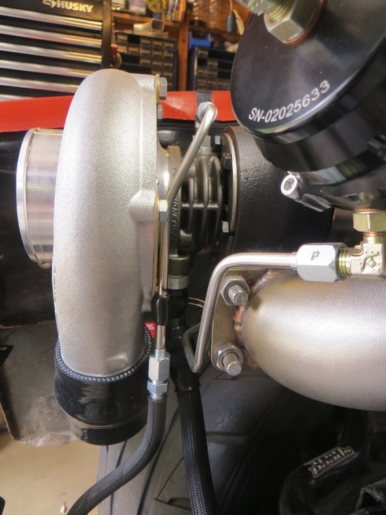
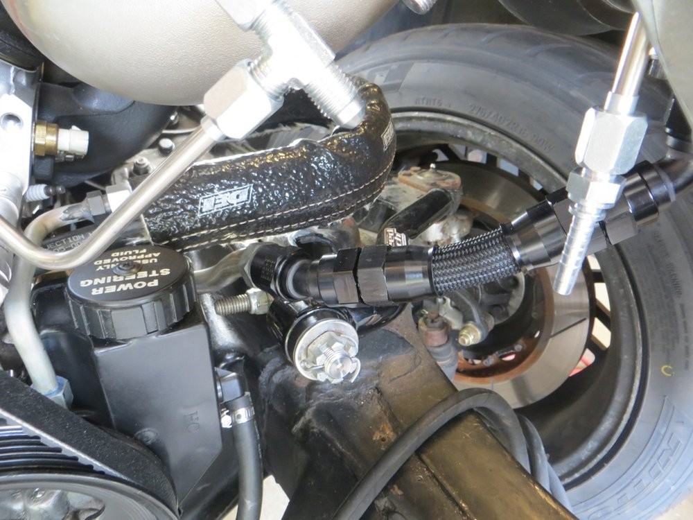
This is the forced bend flex hose as I was mentioned...
The reasoning for mounting the turbo feed line to the subframe was:
A) to get it tucked out of the way vs having lines just floating randomly in space like you usually see
B) I'm going to mount a machined aluminum "oil junction block" mounted on the subframe rail directly below the driver side turbo. This will serve several purposes:
B1) hard mounting point on the subframe to anchor the flexy -10AN oil cooler lines coming off the engine
B2) hard mounting point to allow option of soft (flex hose) or hard (aluminum 5/8" line) feeding the oil cooler in front of the intercooler
B3) threaded location to mount the oil temperature sensor on the return side from the oil cooler
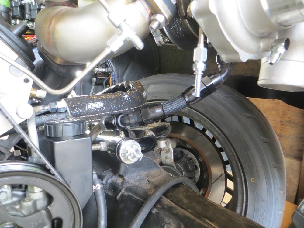
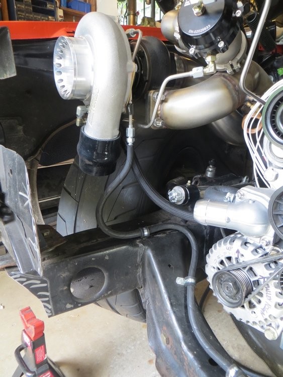
B4) have two angled (30-40 degree) ports for turbo feed lines on the cooler-return side, to mimic a Y-fitting (instead of plumbing 90* tee fittings)
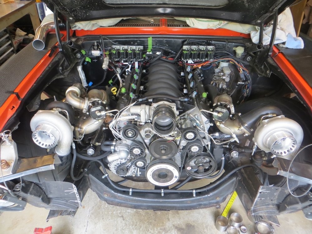
As it sits right now. Getting close!

Wow thanks for sharing!
Posted by Diggymart on 3/3/19 @ 12:40:25 AM