You must be logged in to rate content!
148 minute(s) of a 341 minute read
9-29-2009
Lunchtime update! I will answer questions and respond to comments later tonight!
Around September 2008, the front wheel tubs were all finished up and I moved out of the first garage. The whole building was leased and I got the boot, but no hard feelings because that was the original deal.
I attended H2O last year in my stock mk5 daily It was nice in a way because I didn't have to worry about anything other than hanging out and checking out all the cars. Plus I could take minimal time off work, because driving through the night in a new car is no big deal.
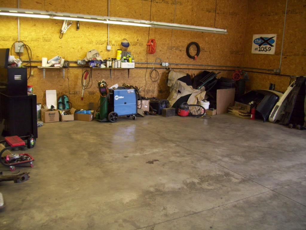
October '08, I moved into the new garage! It's part of a 5000 square foot warehouse owned by my friend's dad. It's adjacent to a 35000 square foot machine shop, they're in the CNC machining business. This particular building is basically their toybox. Any car guy's dream really! I'm not going to post direct pics of their stuff, but check the backgrounds if you're interested. I also gained access to some sheetmetal tools, which will come in handy later!
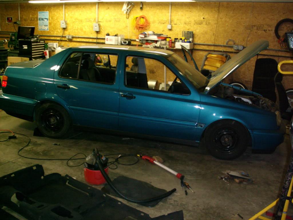
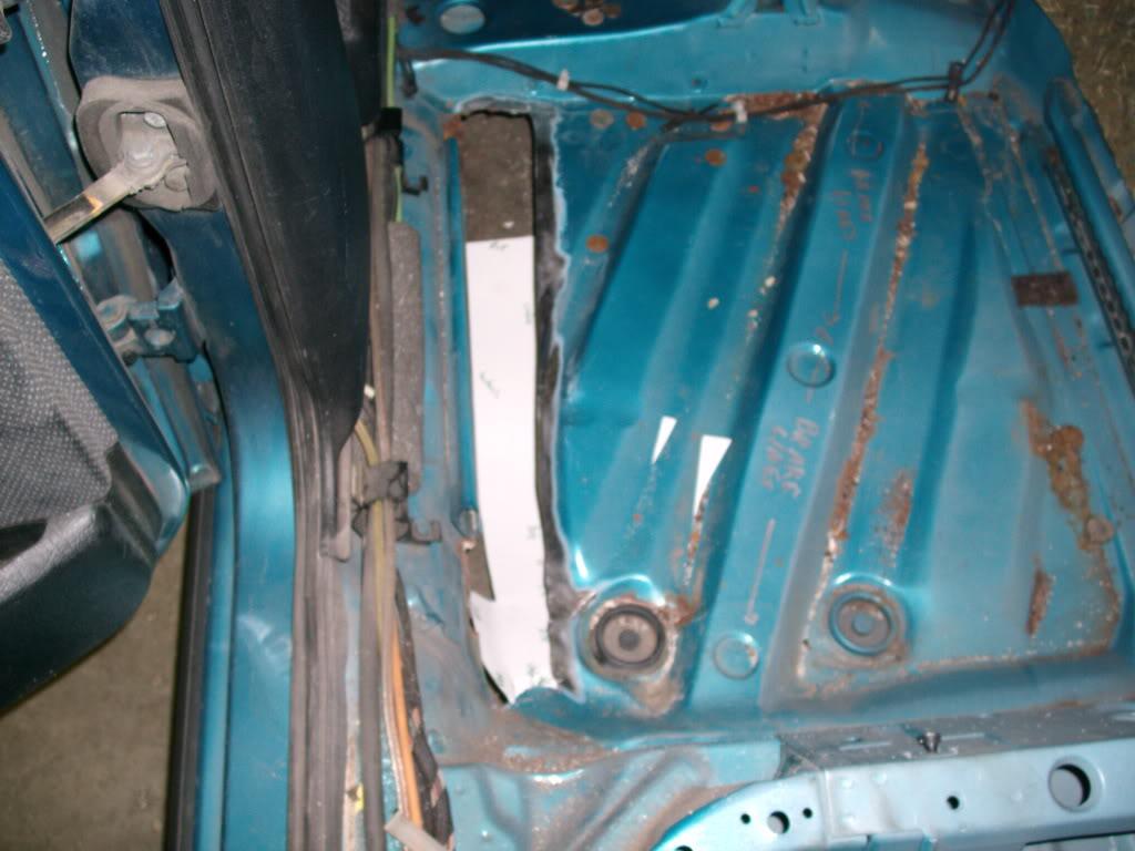
November and December I spent fixing rust holes in the floor.
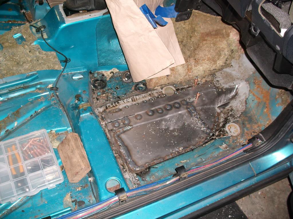
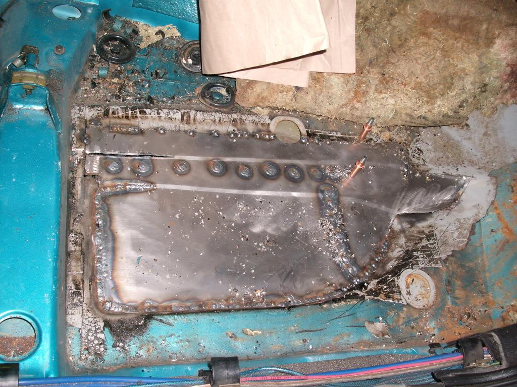
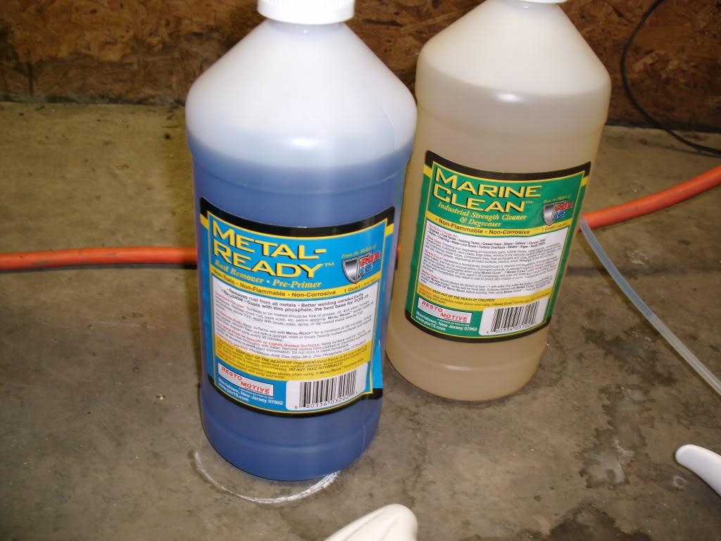
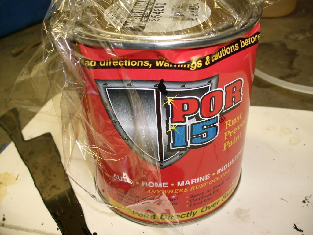
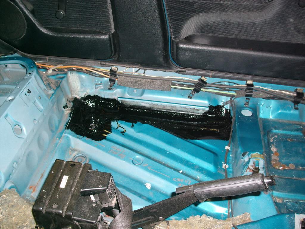
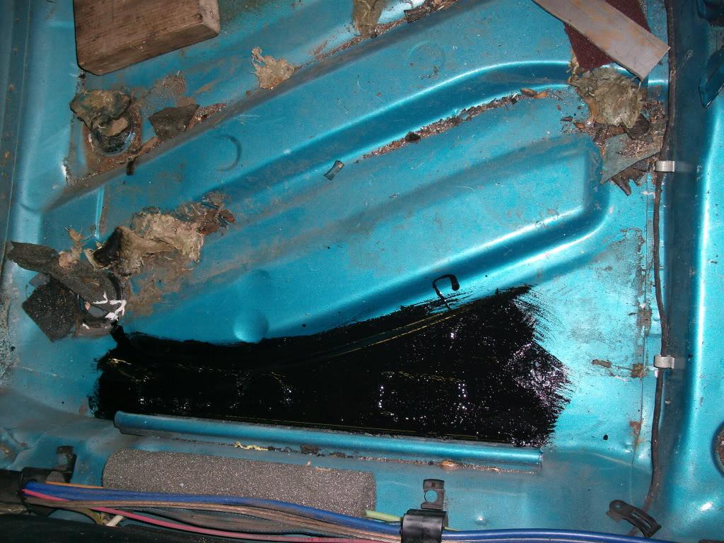
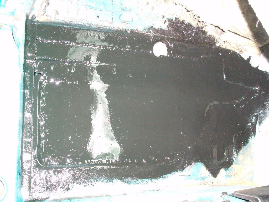
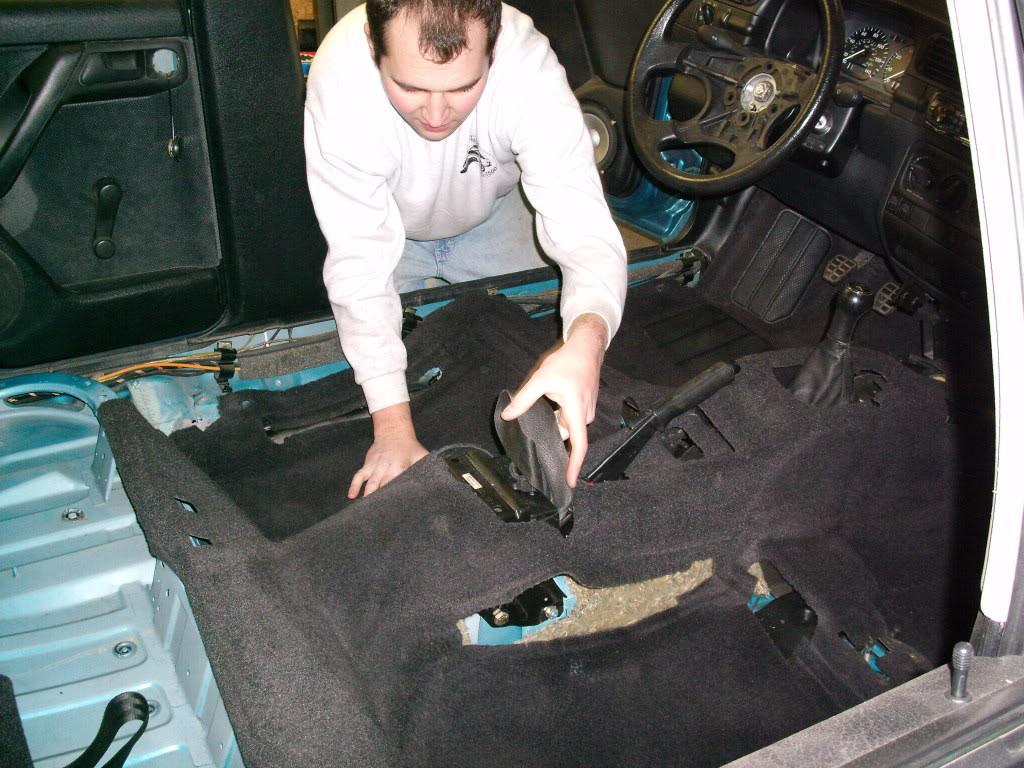
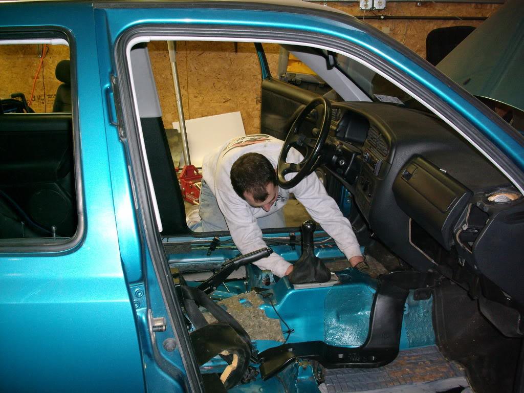
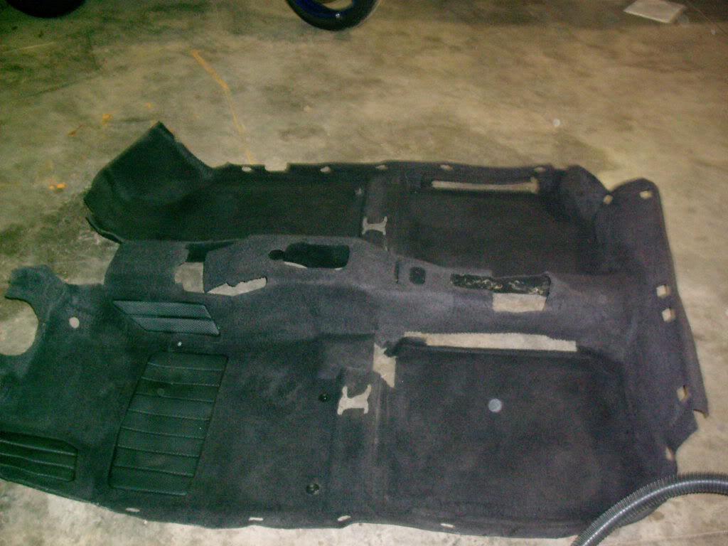
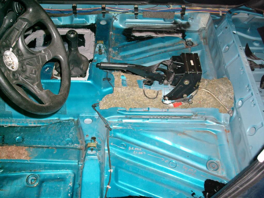
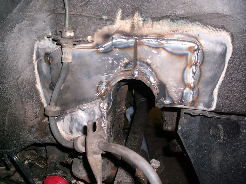
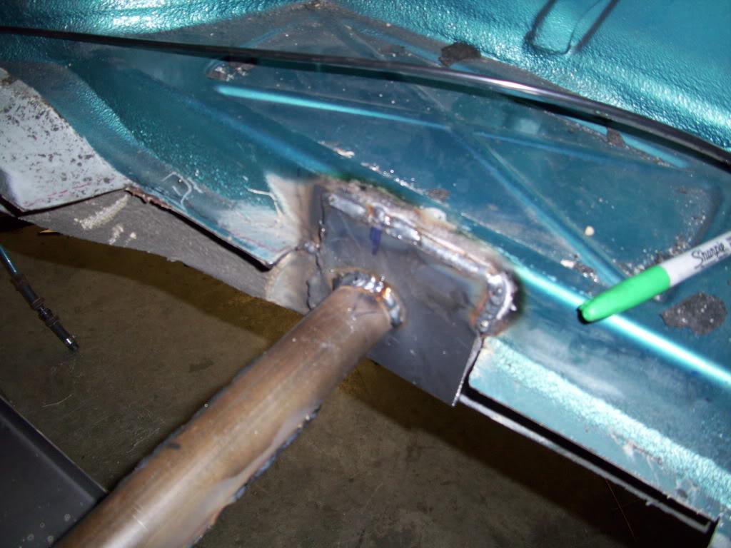
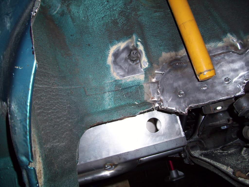
Then I reinforced my c-notch by adding a 1/8" steel plate to the area, plug welded in a few spots, to give it strength. I also fixed the bad welds. This is about half welded in the pic:
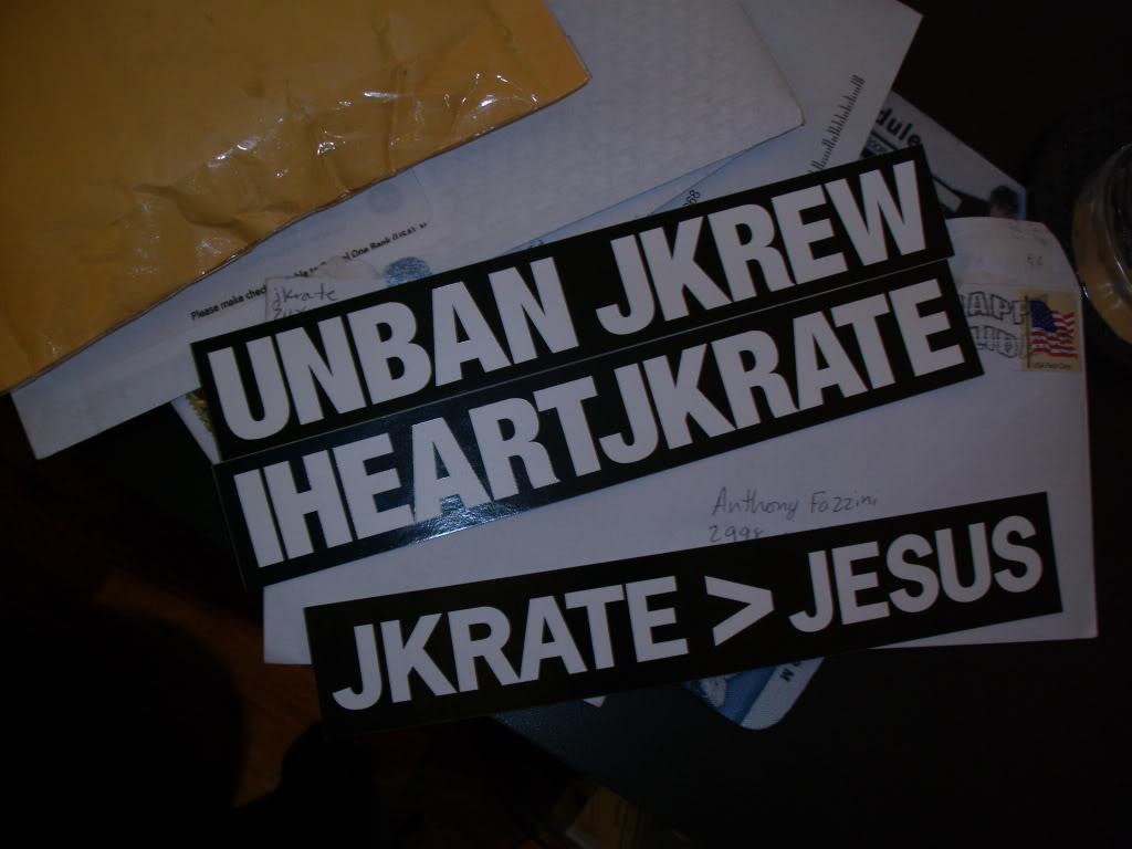
Some cool people sent me some cool stickers. Unfortunately I missed both Jason and Kate at H2O this year yet again, I really wanted to meet both of them
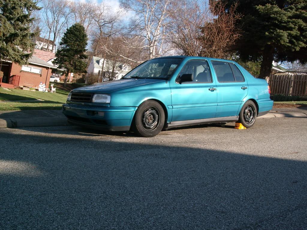
I got the car inspected in January, and posted these pics: http://forums.vwvortex.com/zerothread?id=4178991
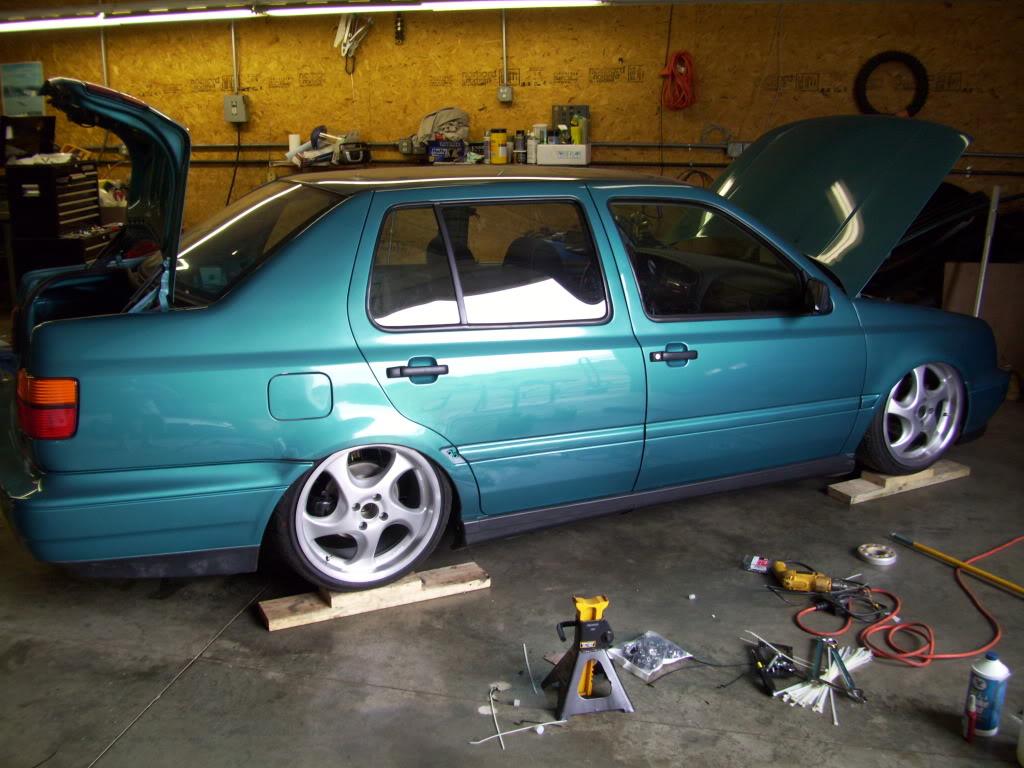
I had the H&Rs at this point still, the car ran and drove for hte last time until September 2009!
P.S. note the photobucket album names. All the heavy build pics have been hosted since January, on a public but well-hidden photobucket account . I had a bunch of non-vortex friends watching the build.
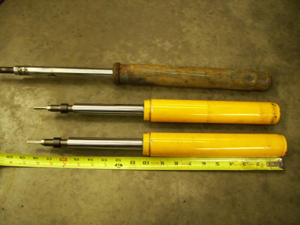
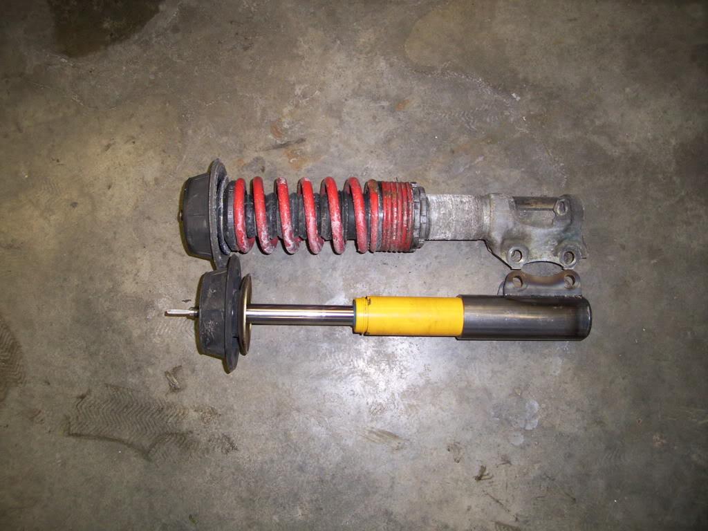
The pics I posted above laying frame didn't have the Koni strut inserts installed. They were too long and needed shortened, despite being the shortest available. I decided to do it myself. These are the shocks I'm currently using in the hydraulic coilover setup.
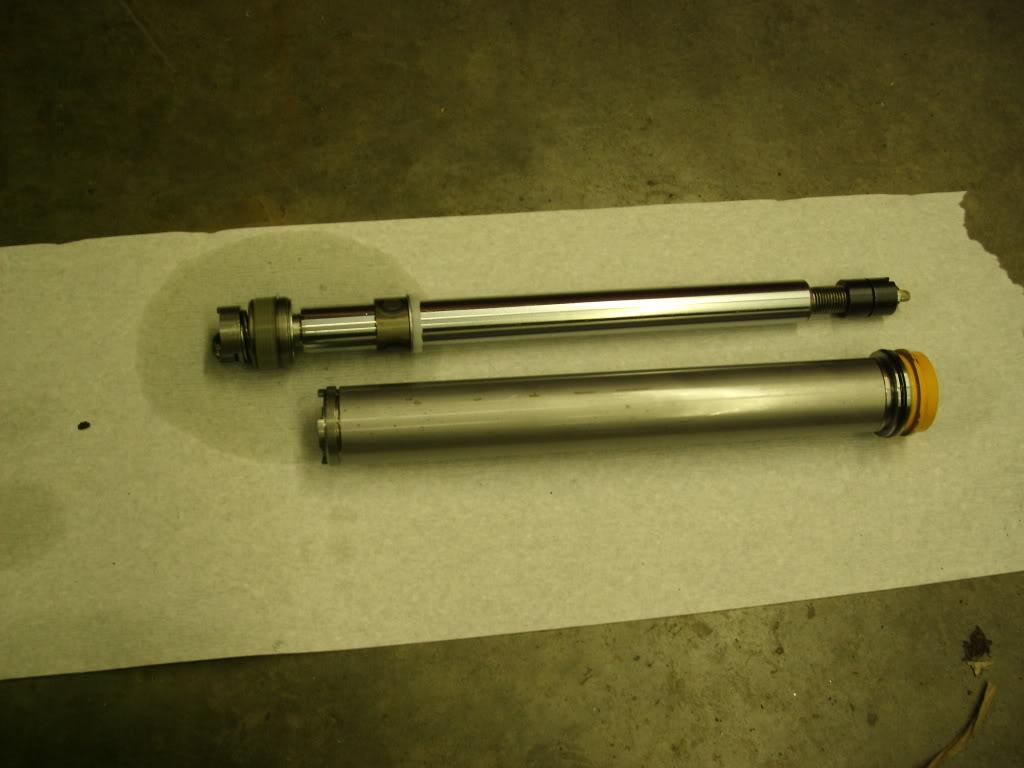
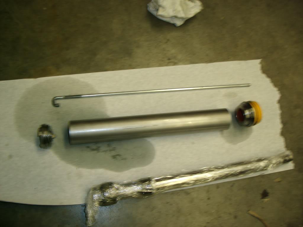
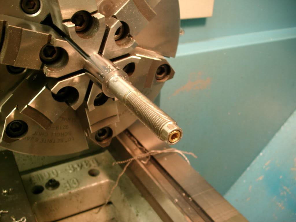
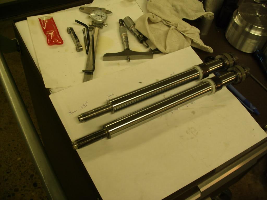
Here are some pics of my Koni shortening. This is an 8610-1436 RACE strut insert. Koni doesn't recommend or authorize this, they will NOT sell you internal parts because this shock is "not user serviceable" These pictures are for entertainment purposes only and I assume no responsibility for what you do with your struts.
Cut out the adjuster rod and uncrimped the top:
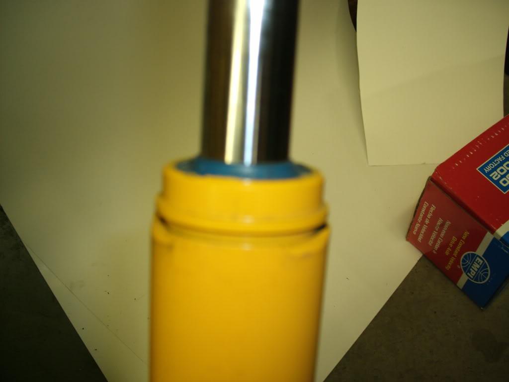
Here is the shaft and pressure tube assembly:
Here is the pressure tube assembly apart:
Turned down the rod, rethreaded, recut the adjuster rod bushing and seal bore:
Cut down the housing tube and pressure tube (housing tube shown):
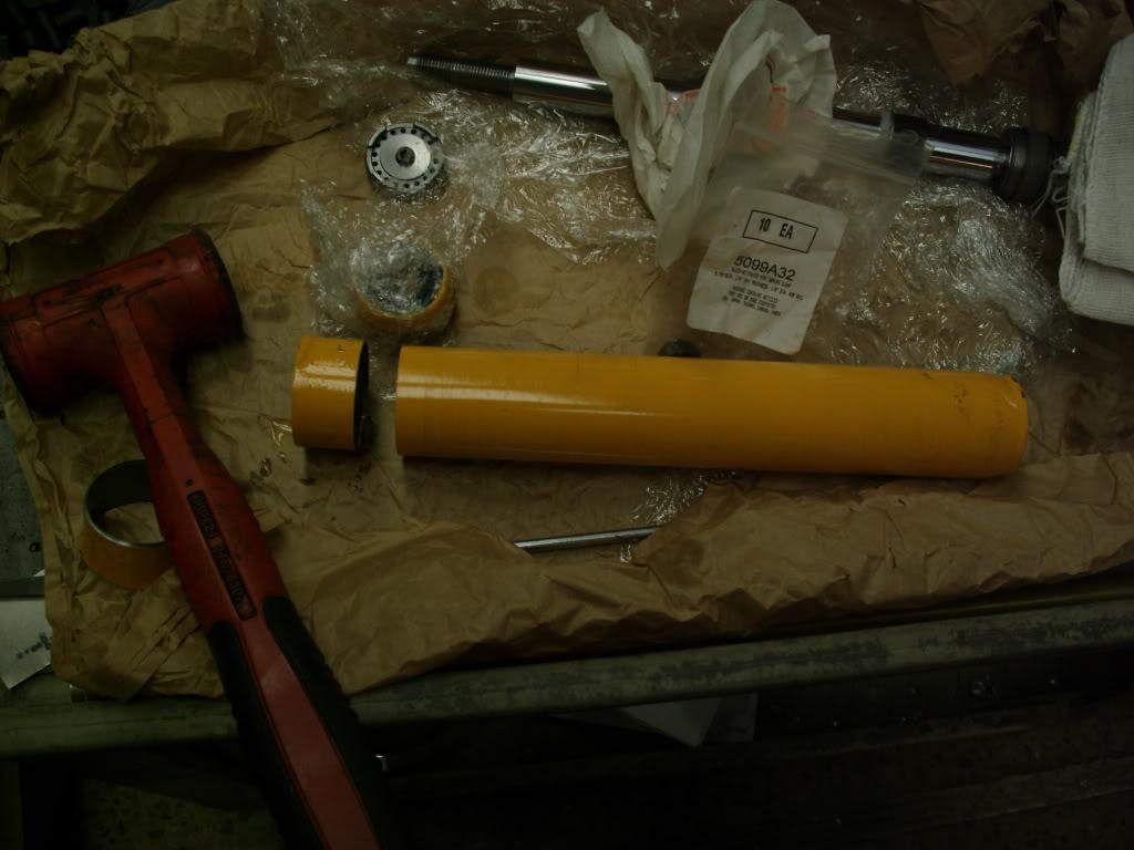
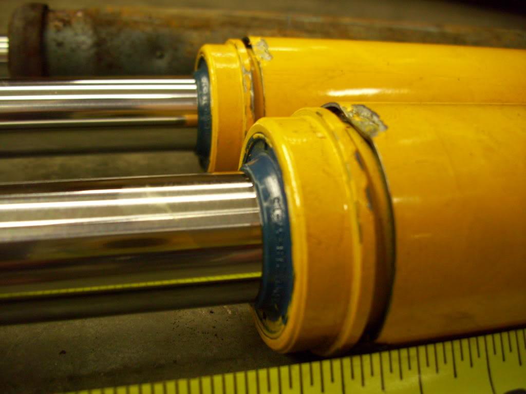
Reassembled and recrimped:
Compared to stock mk2 strut inserts:
Once the struts had been modified, the car laid on the frame with the strut mounts installed
January 17, 2009
The plan changes. Drastically.
I test-fit the new shortened front struts, removed the rear shocks complete, and laid the car down.
The car was parked up on two 2x6's, then two 2x6's were placed under the frame. It laid out, with the front shocks bolted in place
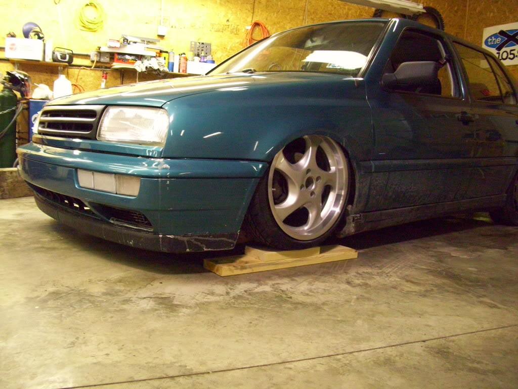
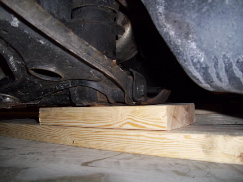

Things were pretty bound up in the front, but it still laid. Tie rod notches and drivers side c-notch in order.
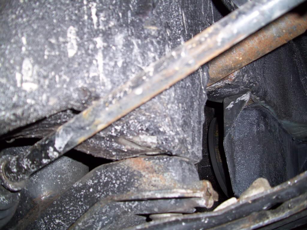
Here's a comparison of the old H&R Ultra Low with the new, shortened Koni.
Then the ugly truth comes out. The rear beam just isn't gonna cut it.
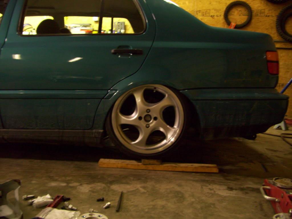
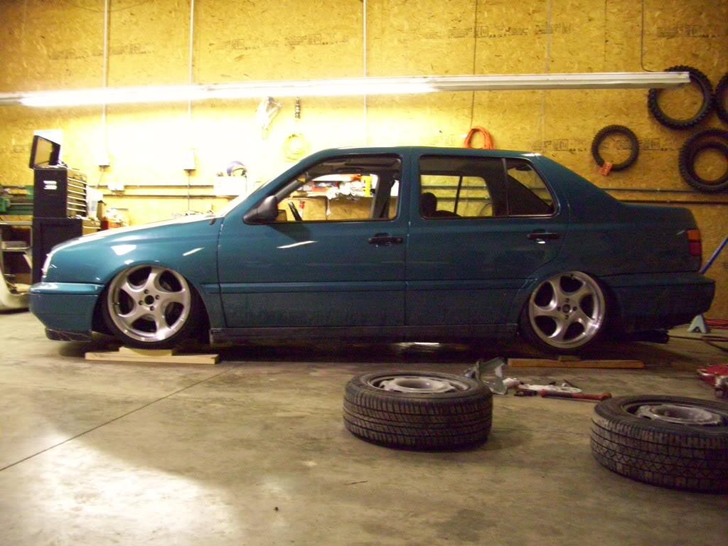
Forward tuck... not low enough... can't roll at this height... more metal must move. Lots of it.
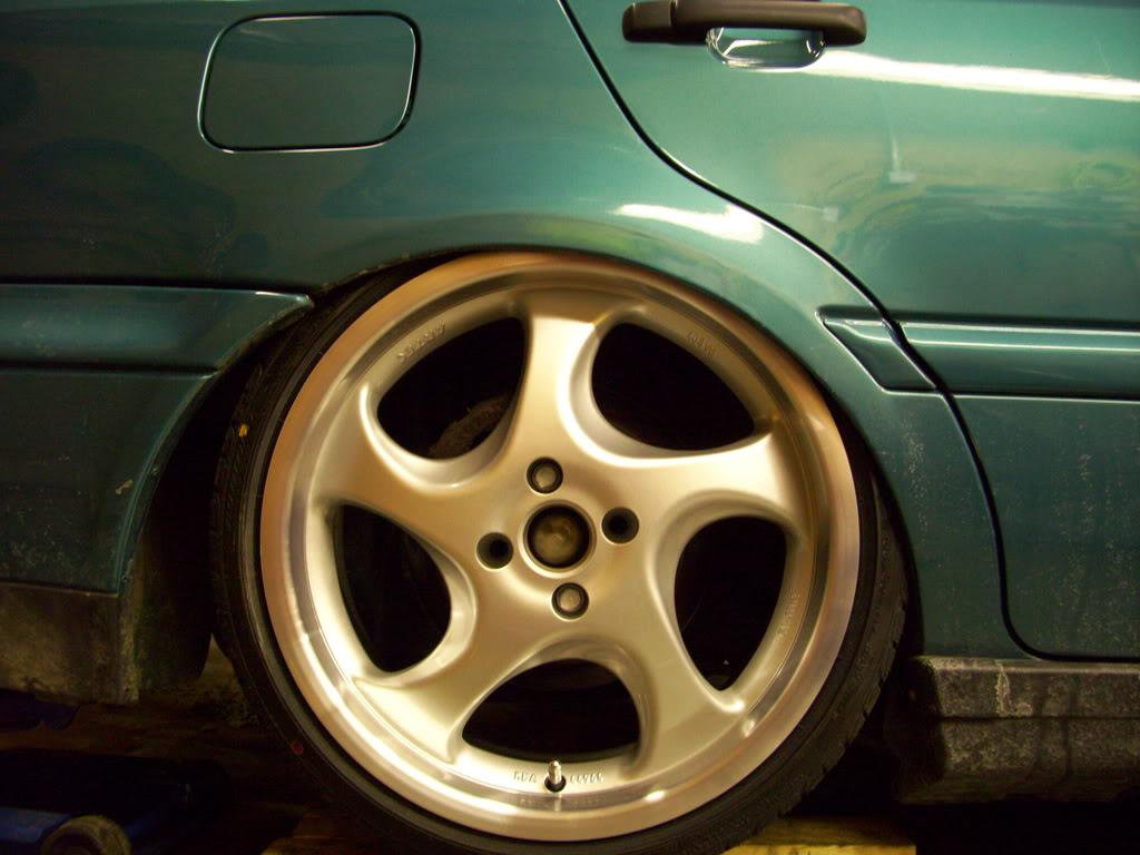
Like all this metal. Permanently added to the "notgonnagobackin" pile.
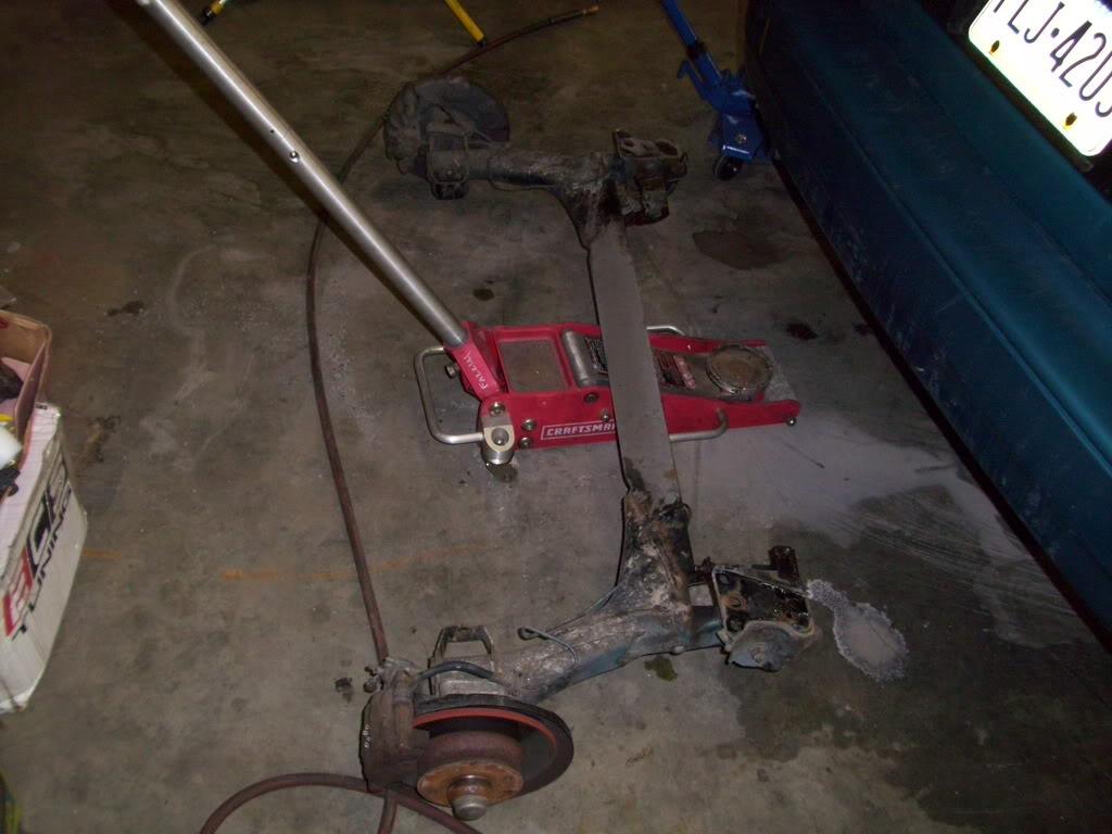
Even some plastic made the chopping block!
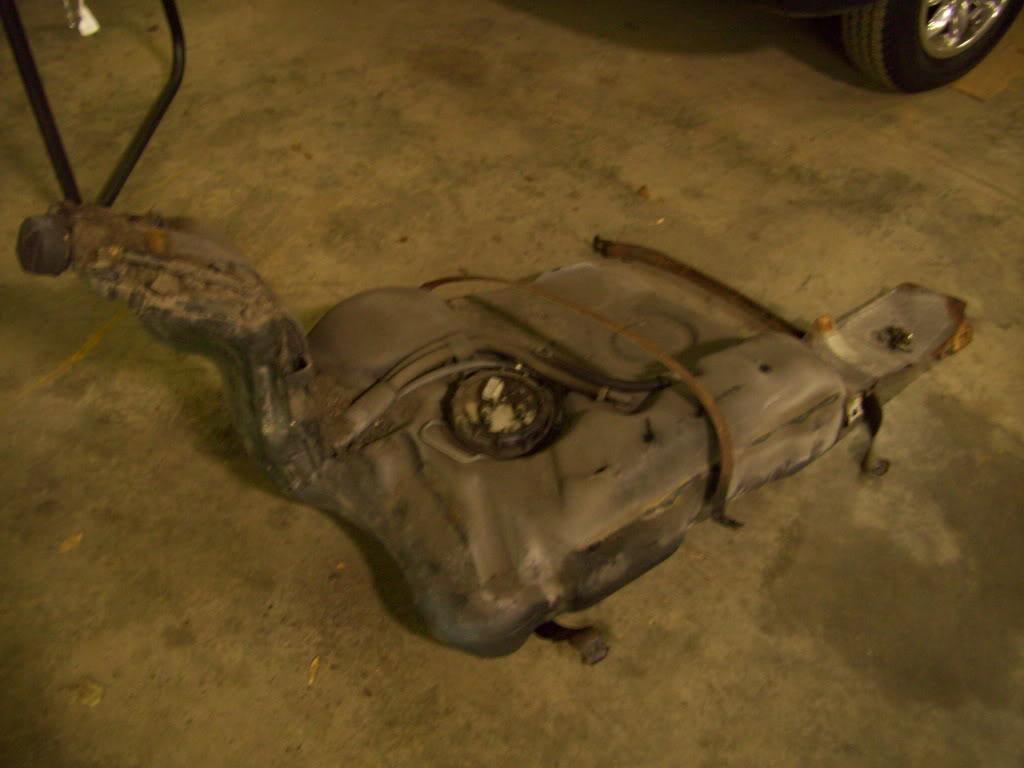
And all this... bye bye!
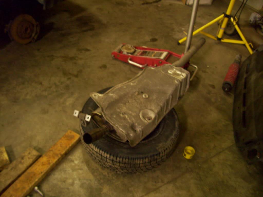
Now with all that pesky crap out of the way, it's starting to look like a proper stance again!
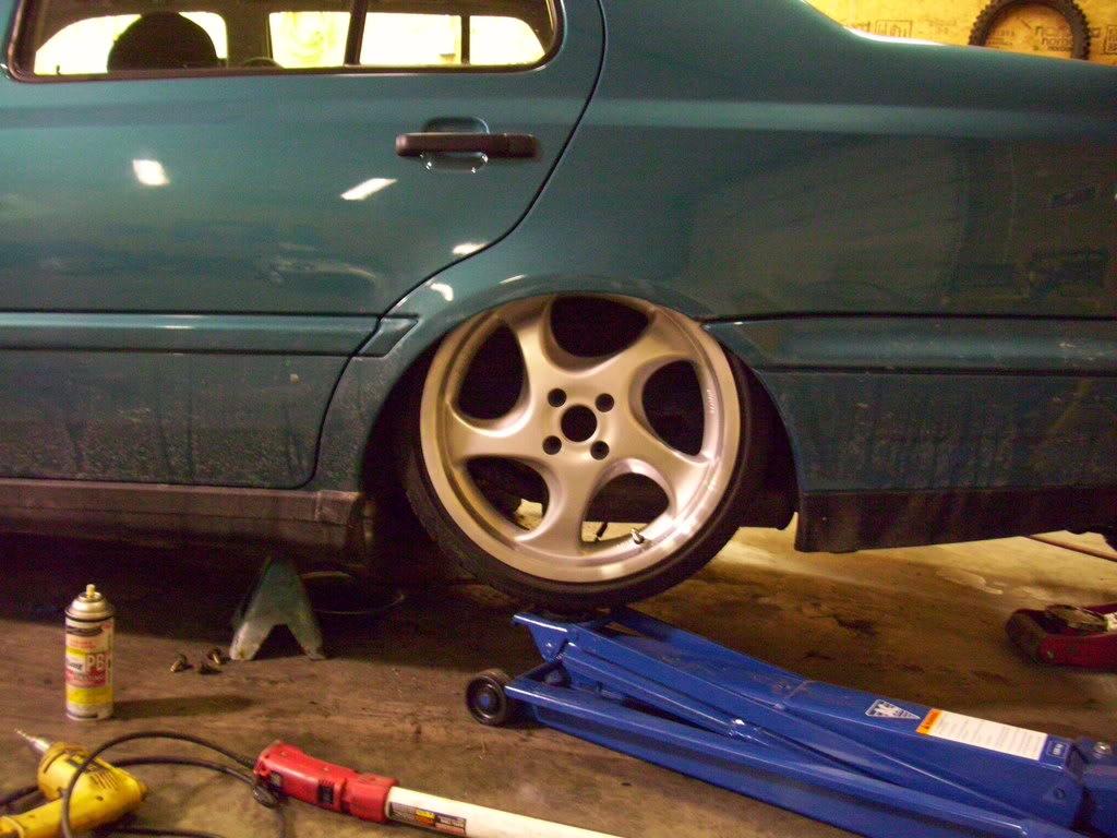
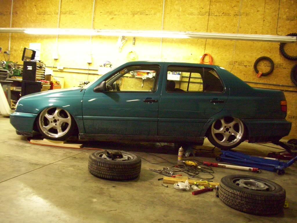
The inner fenders would have to be tubbed also, but that's minor. Now what should I do with the suspension??
So I consulted my buddy Mitchell for his vehicle dimensions. 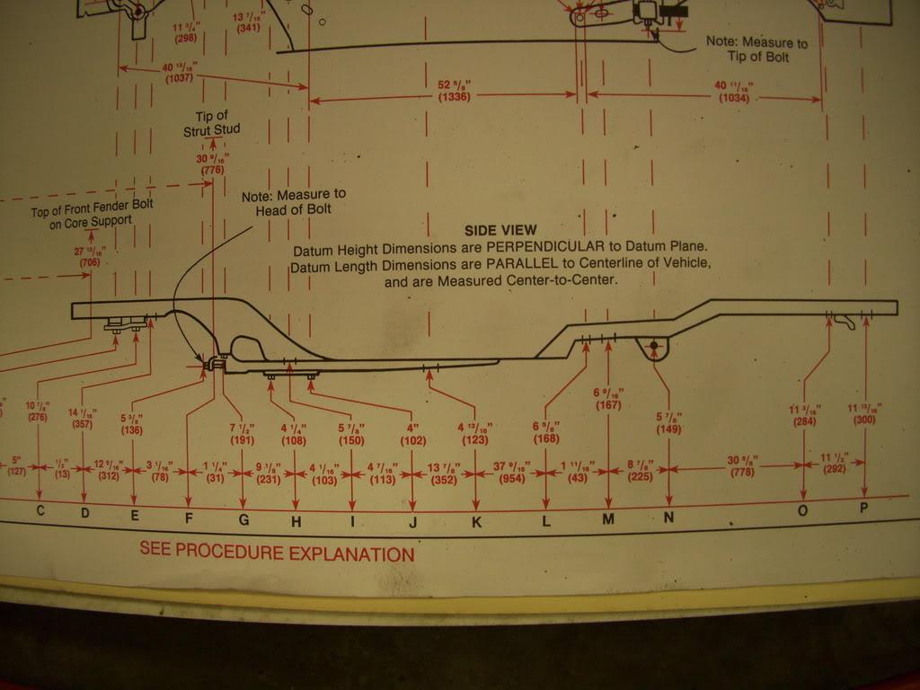
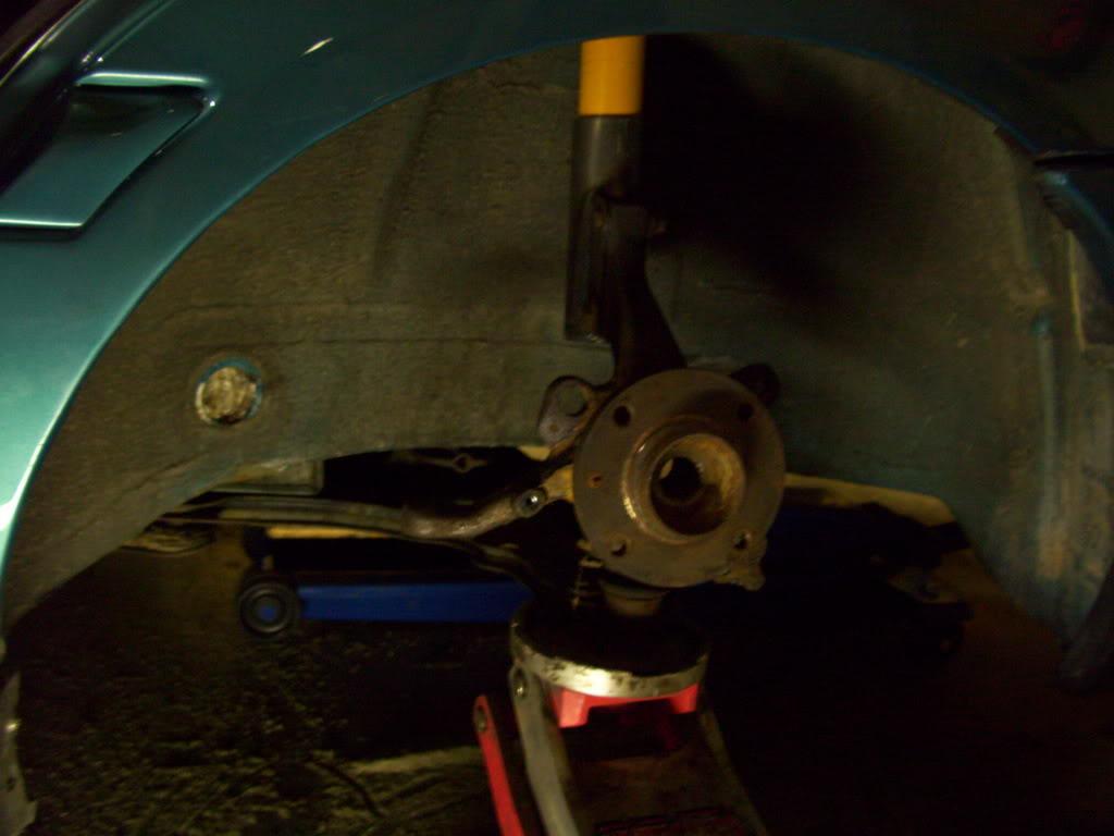
And had a front mk3 subframe laying around. Now I had seen this done before on a track prepped corrado in the Suspension tuning forums. One blurry pic and a few measurements were enough to convince me it was possible. On to some test fits!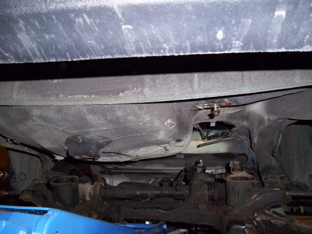
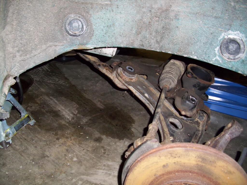
Hey that frame rail is pretty close to the mounting point... this could work!
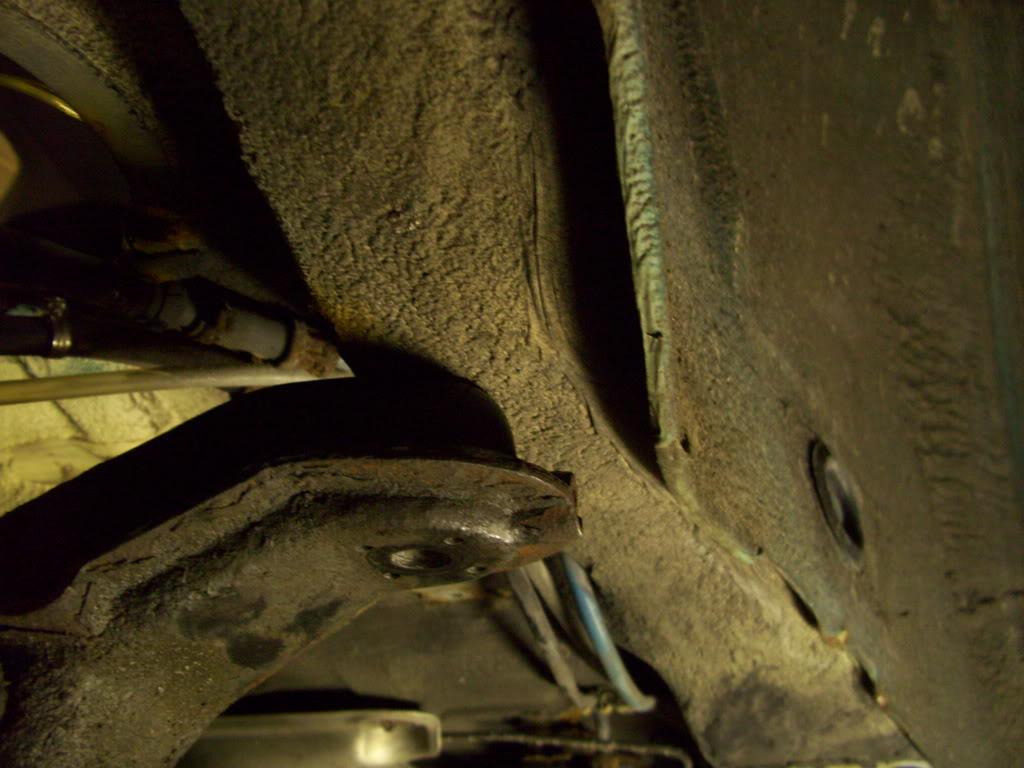
It looks pretty good under there!
So here is the master plan, drawn quite well with CAD. Or a pen on a dirty piece of paper.
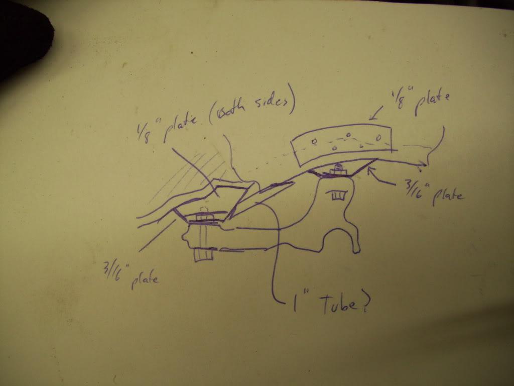
Left is toward the front, right is toward the rear. The area just above the left side of the drawing (forward mounting ponits) is just below the seat crossmember. This is where the rear seatbelts bolt in, and is a heavy structural section of the car. This is one of the strongest places in the unibody, making it well suited for the loads of a suspension. The rear mounting points are right below the frame rails. Plating will be added and mounts will be made, with some tubular bracing into the existing structures.
Now most of the mid-engine IRS setups use the subframe mounted in the stock orientation, with the pancake bushing toward the rear and the tie rod behind the rear axle centerline. This is nice for motor packaging, but reversing the subframe allows it to integrate much better into the strongest parts of the unibody. Since I won't have a motor back there, I plan to reverse it. The frame rails just below the rear arches are super strong, the seat crossmember is already very well reinforced, and the stock beam mounts are right there and available to have braces welded in the area. It's almost like it was supposed to fit there!
Dinnertime, more updates later
Jan 31, 2009
The rear fender cutting begins. I knew early on the corner of the door would be the holdup, I wanted to be sure that wouldn't keep me from getting max low. 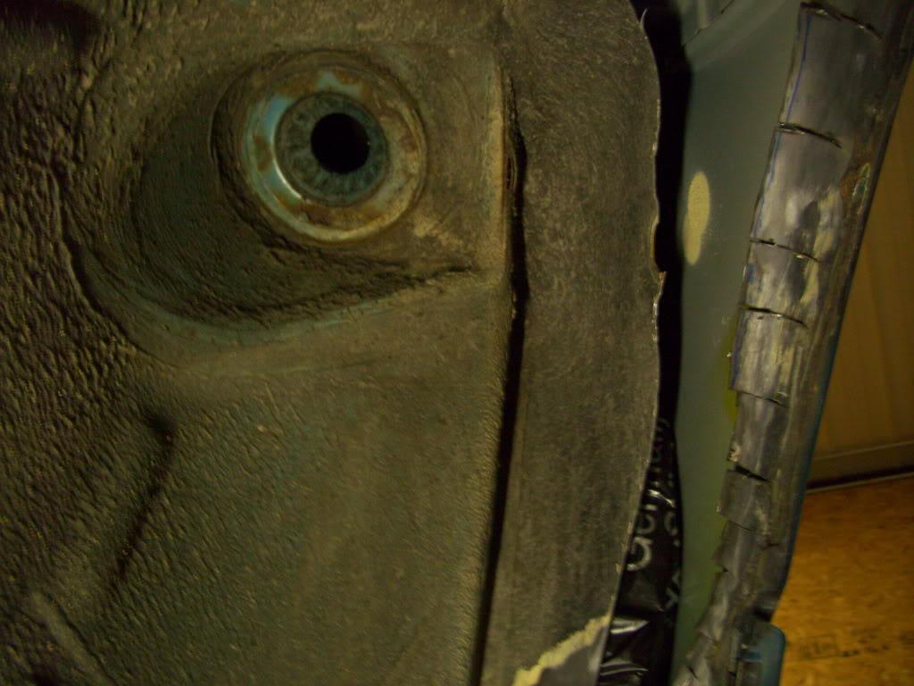
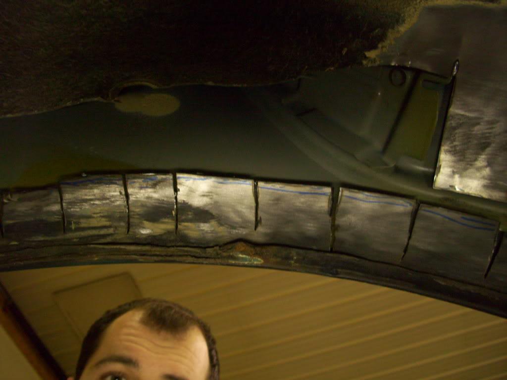
At this point I realize how ridiculous this has become. The rubber studs that hold the clip-in rear molding section will need to be moved, since they will hit the tire
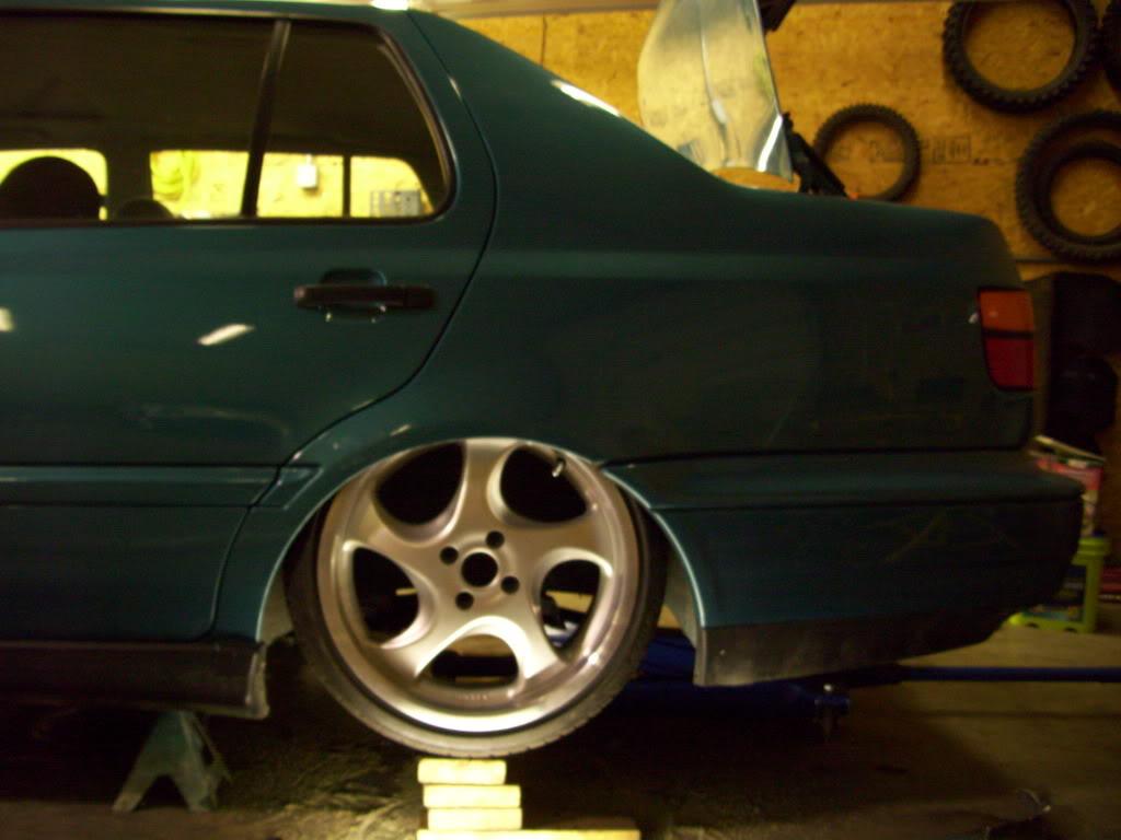
After the trimming, the wheel could still tuck but could be brought out much closer to the fender, with much less camber too.
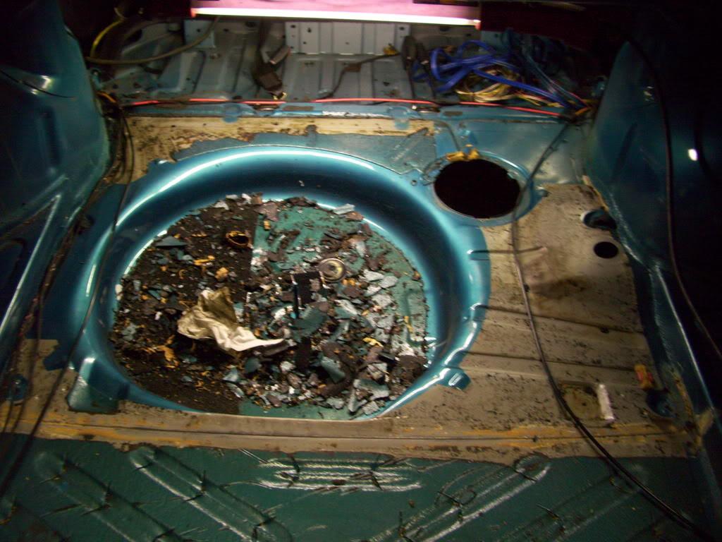
I started stripping the trunk sound deadener where I would need to cut out the floor, to make the cuts cleaner and make cleaning and welding easier later down the road
I stripped the undercoating from some key areas below the floor where the subframe would mount
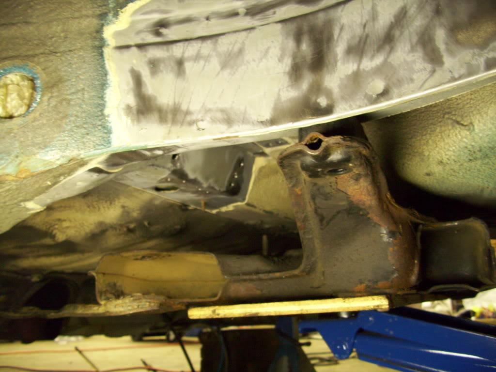
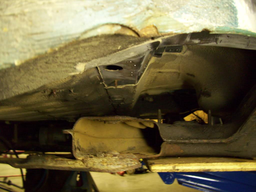
here's a bottom view of the new clean slate!
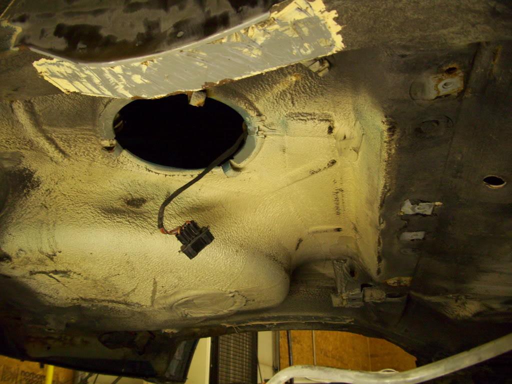
Feb 3, 2009
Floor is gone.
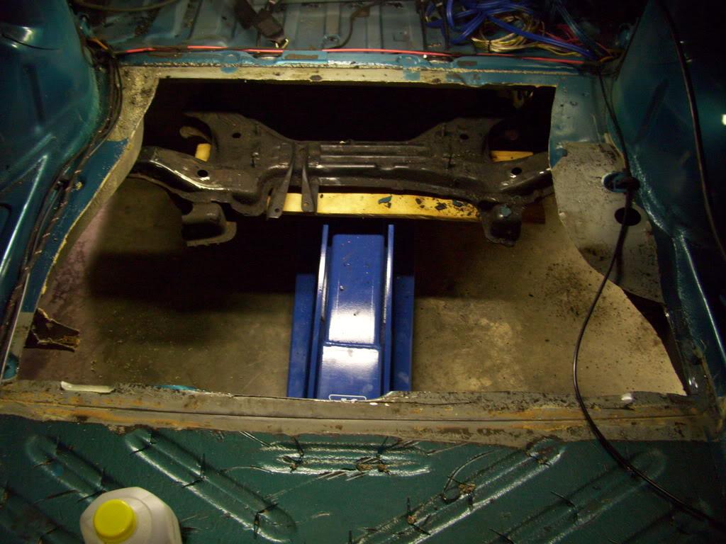
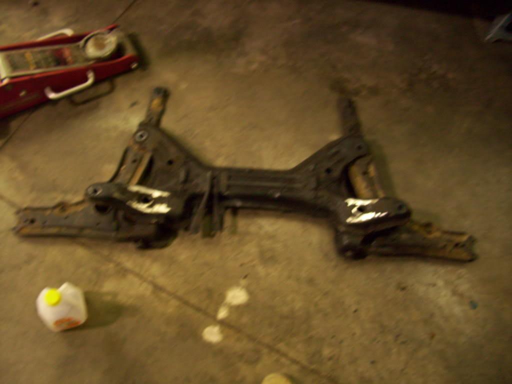
I took out the subframe and took some measurements from it, comparing them against my Mitchell book.
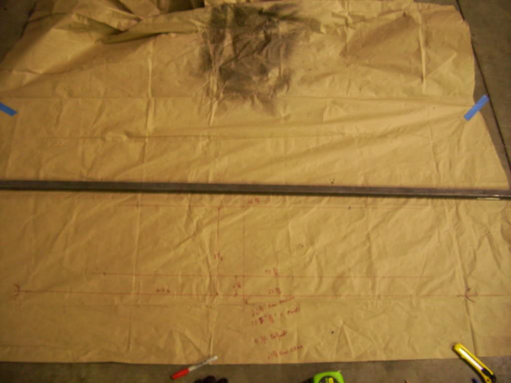
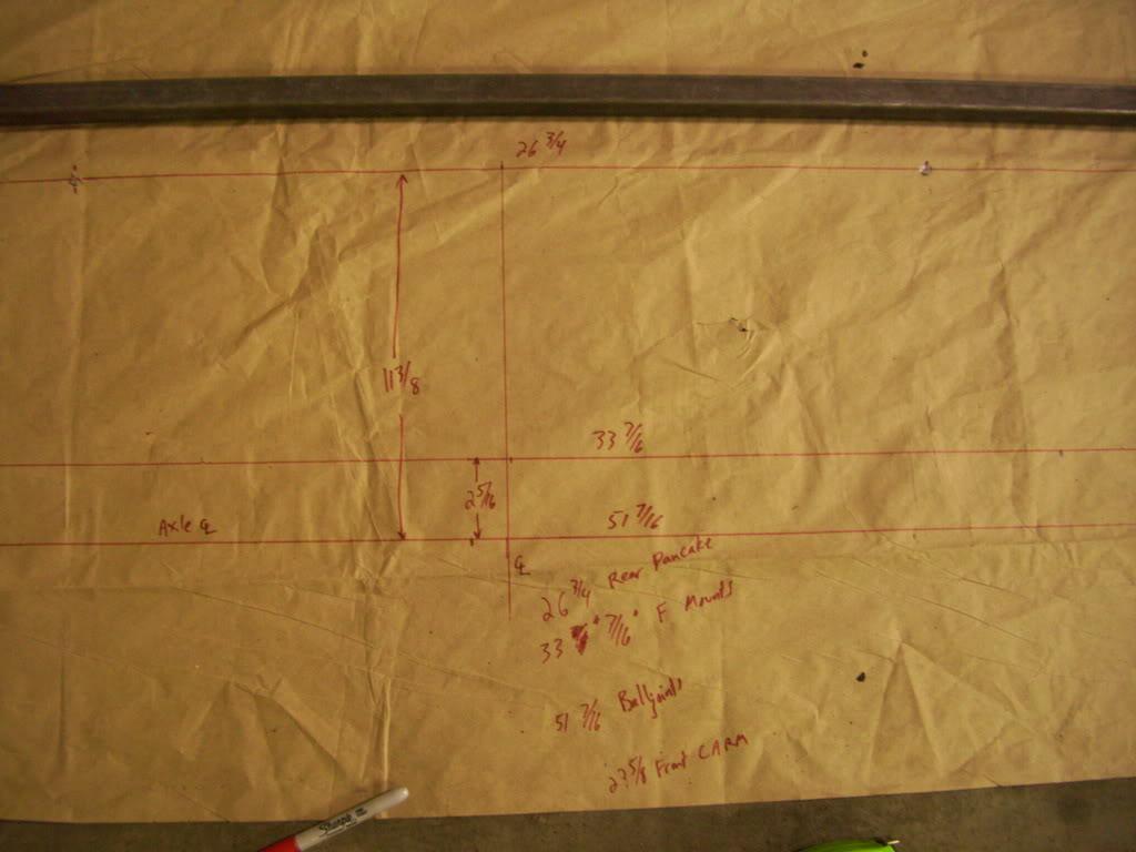
Feb 4, 2009
I begin taking measurements for the rear axle centerline. I used two methods and compared them. The first was to trace the steel arch on the unibody, then use geometry to find the center of the circle, assuming it was a perfect circle
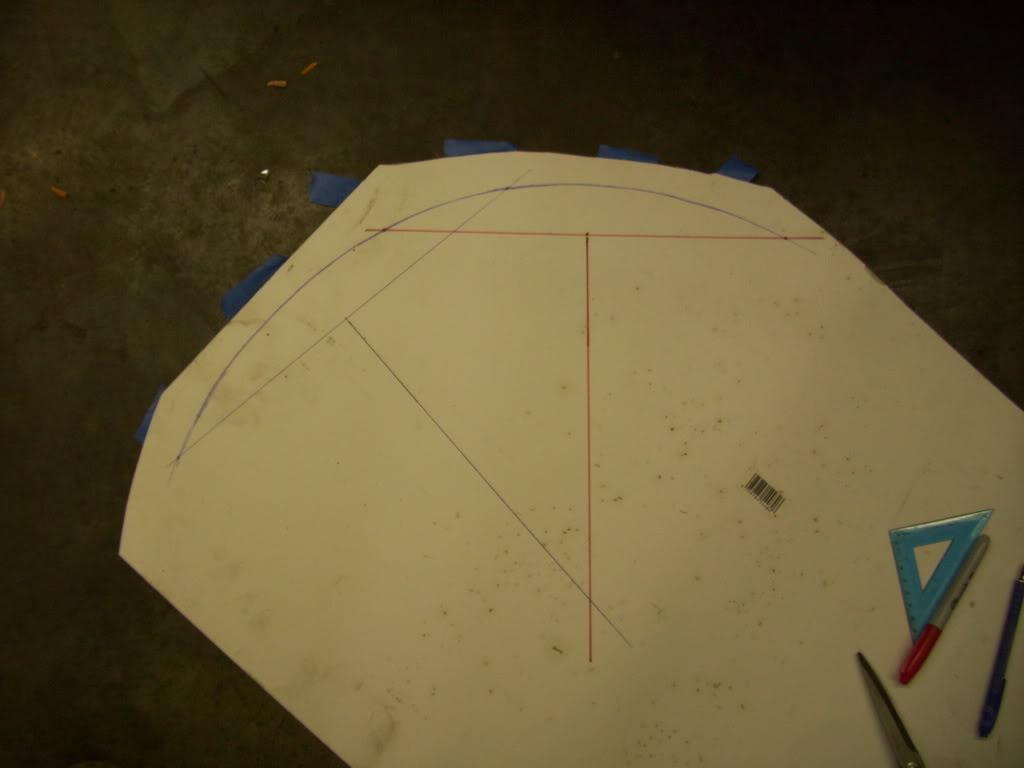
Then I stretched a string, level with the bottom of the doors, to the rear bumper. I found the center of the opening
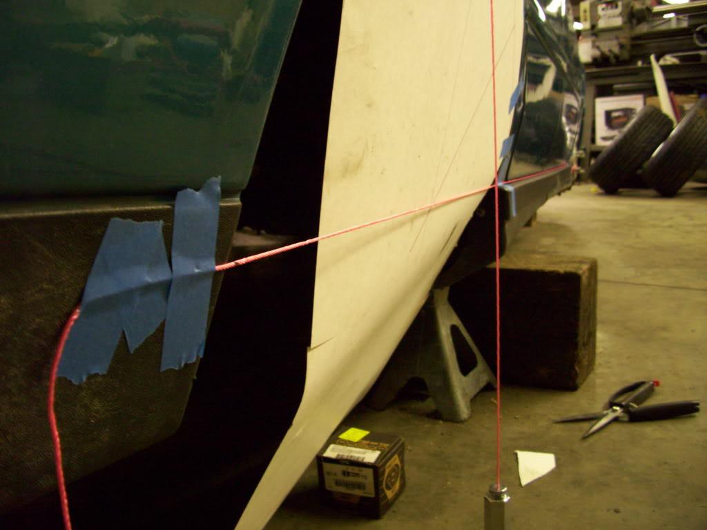
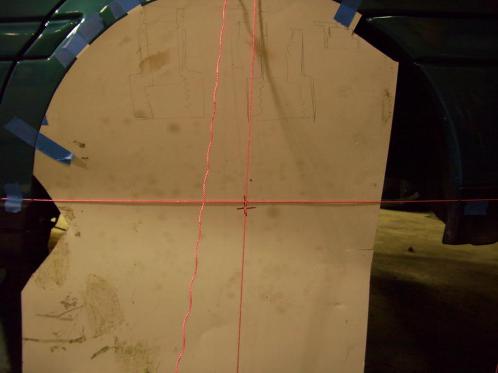
When comparing the two, they were almost identical, so I could use either as a way to center my subframe.
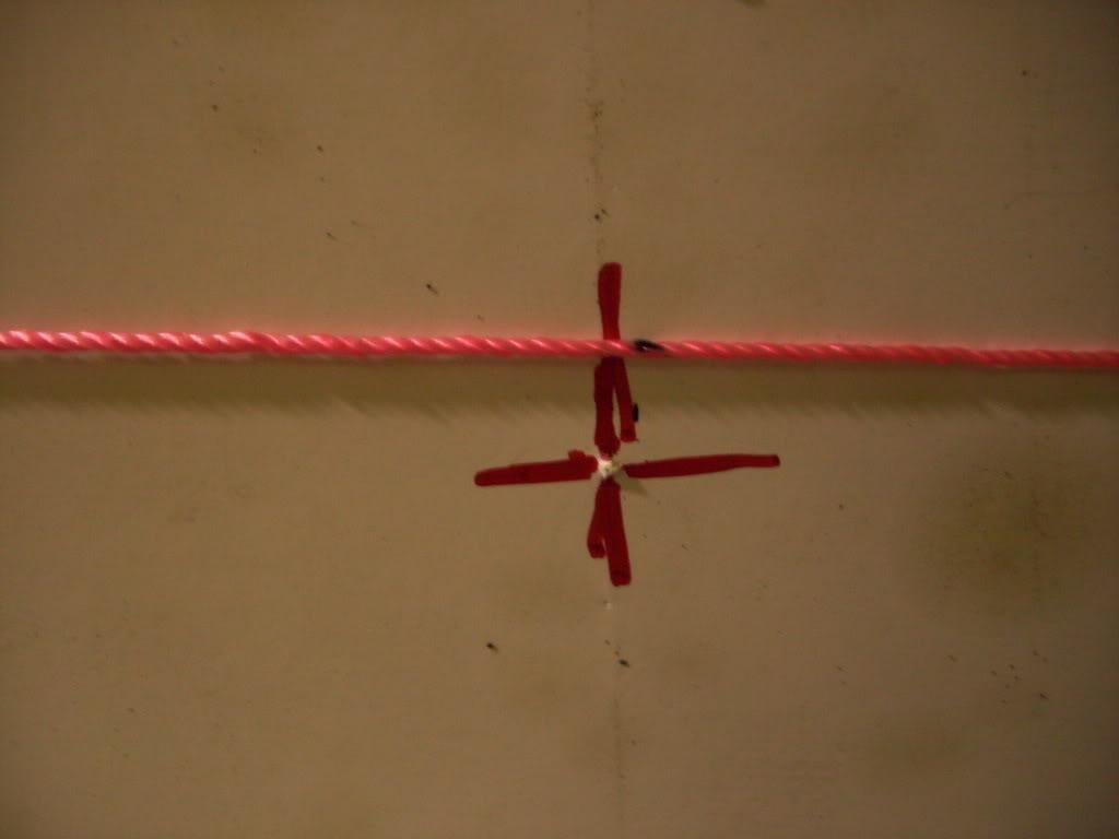
The black dot on the string is the centerline using method #2, the intersecting lines drawn on the paper are using method #1.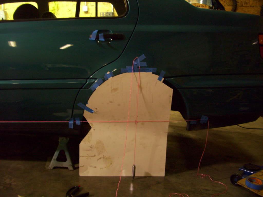
Feb 9, 2009
I marked the centerline onto the frame rails, then used my previous measurements to determine roughly where the subframe mounts would weld, and cut out the pinch weld in that area.
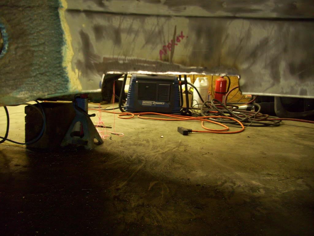
Then I welded the two panels together and ground it smooth, since the area would be plated and then re-welded again.
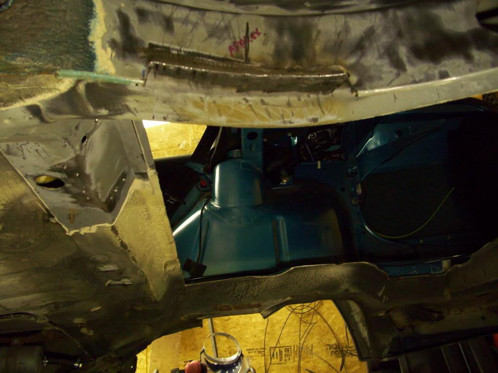
I did the passenger side too
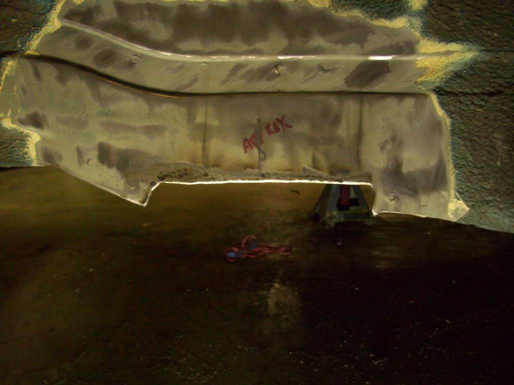
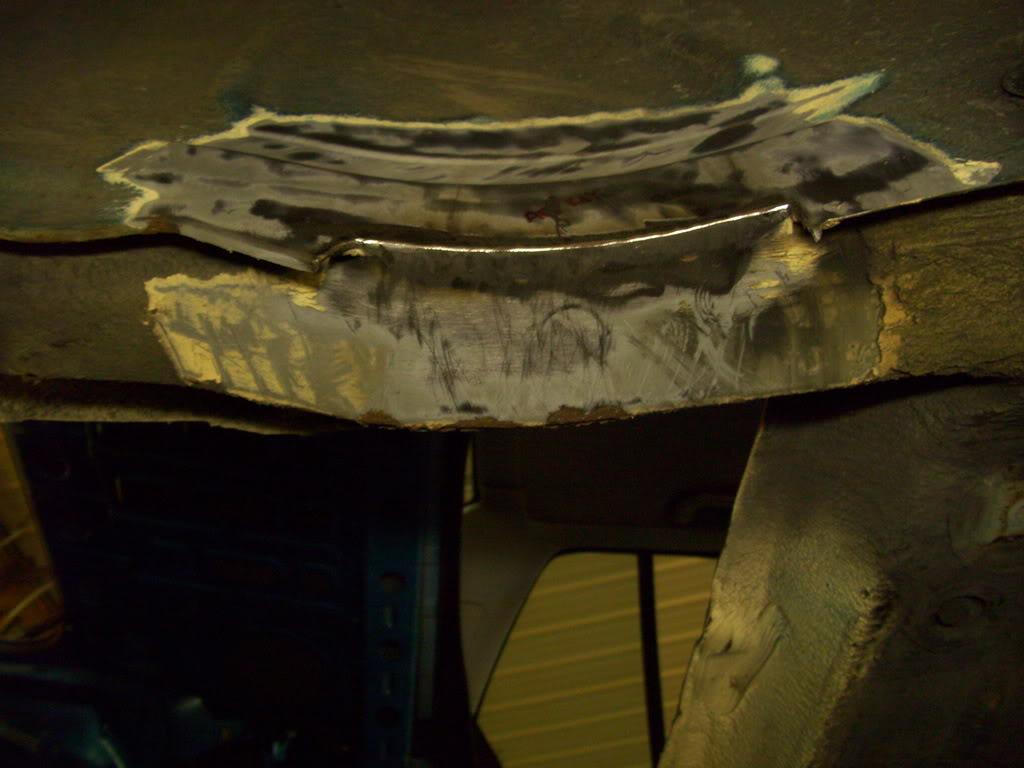
Feb 13, 2009
I plated the bottom sides of both frame rails in preparation for the new subframe mounts. 1/8" HR steel pate, 1020 steel. MIG welded (just tacked at this point).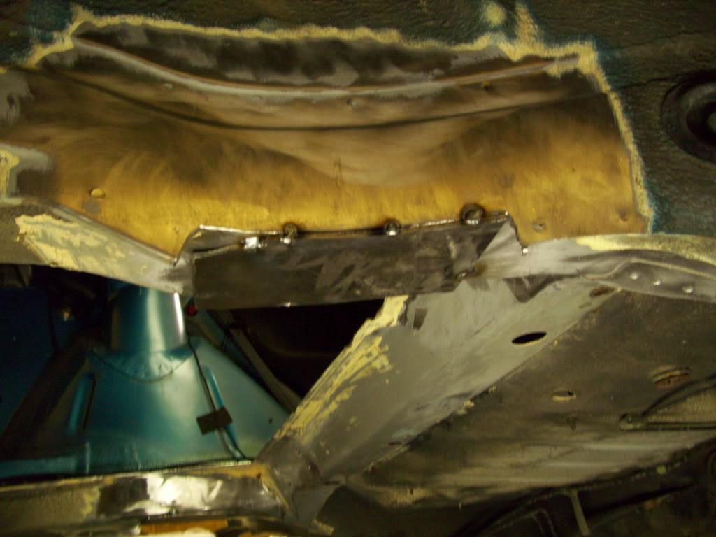
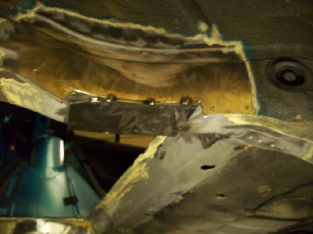
Then I made the rearward mounting points for the subframe from 3/16" steel plate, with a 14mm hole drilled through. The stock holes are 15mm with 12mm bolts for plenty of alignment slop, I will be doing all my welding using 14mm bolts in 14mm holes to minimize any distortion.
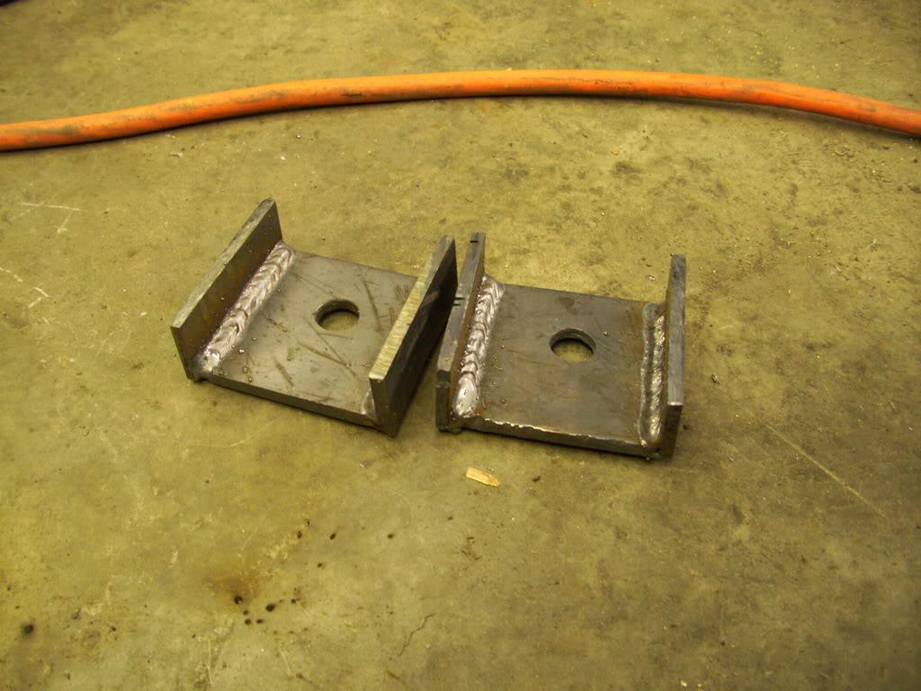
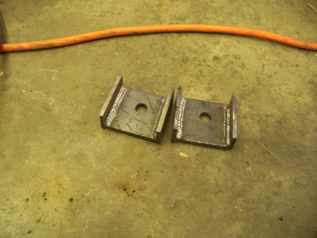
Here they are mounted to the subframe
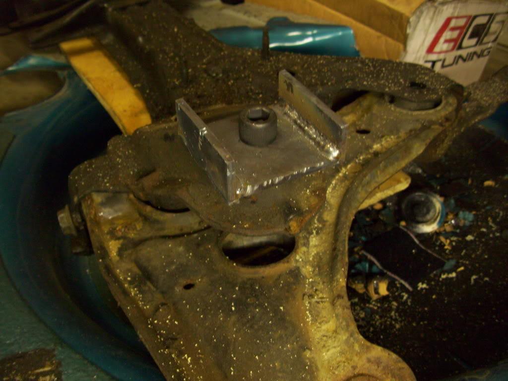
It fit nicely into the plated section
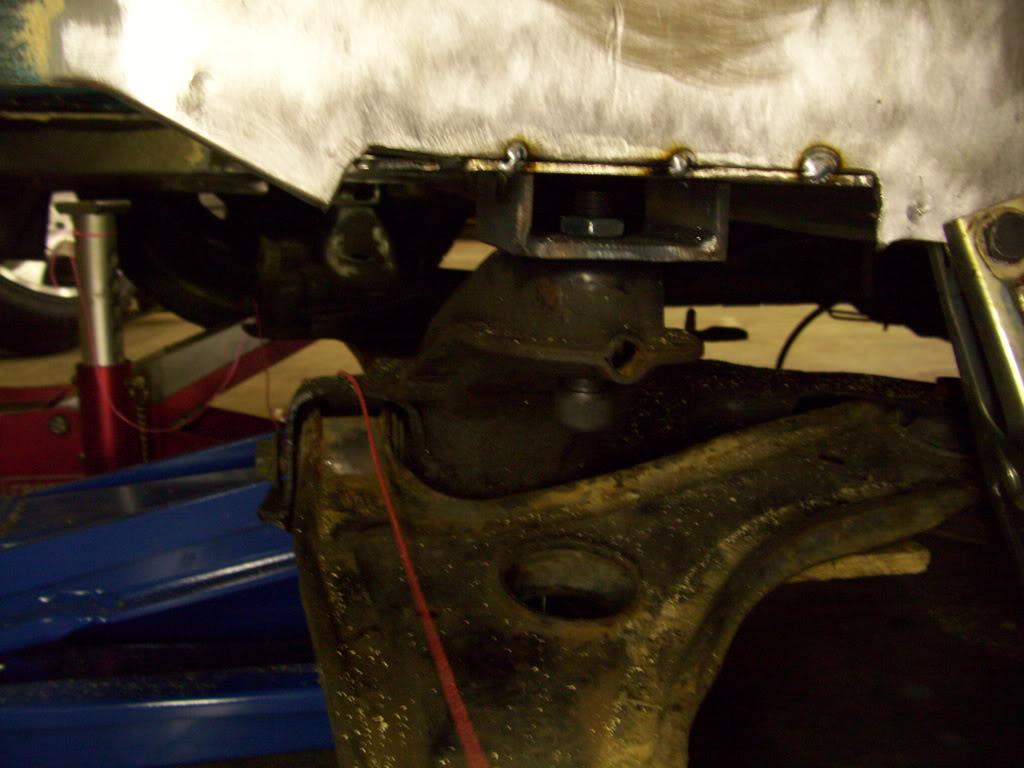
You can see the pink strings I used to cetner everything up, which were suspended on jackstands and dozens of careful measurements were taken.
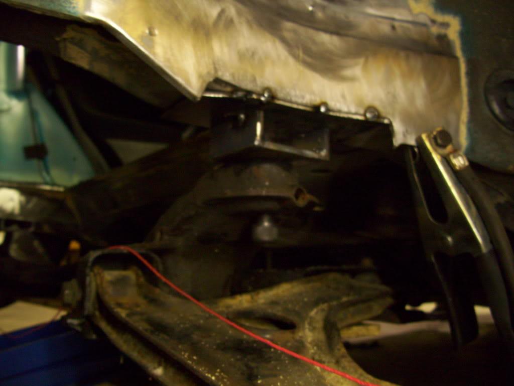
I mounted a strut into the stock upper mounts, and threw on a wheel
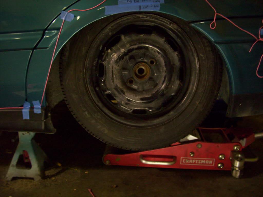
Now this is where things get interesting.
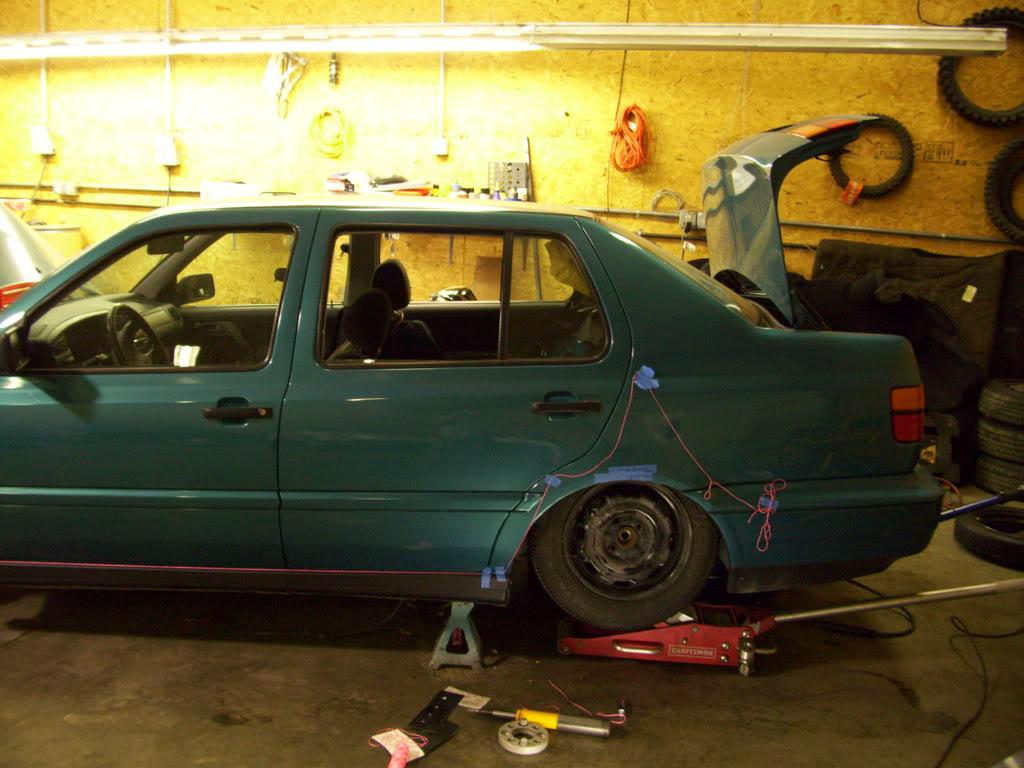
With the axle centerline placed directly on the arch centerline, within 1/16" accuracy, the wheel looked too far back. After some confused thinking, there are many optical illusions at play here. I will need to call in reinforcements here.
In the meantime, I decided to build a new rack since I won't need steering in the rear.
Feb 15, 2009
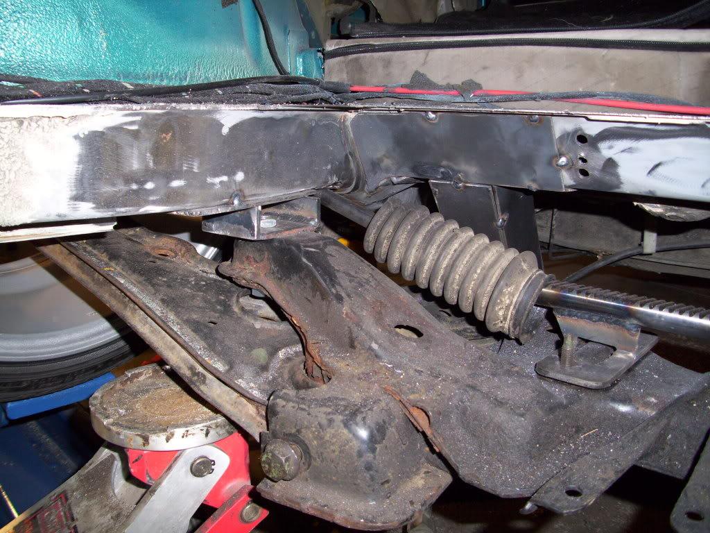
I removed the rack gear from a stock rack, and welded it up on spacers to bolt to the stock rack location.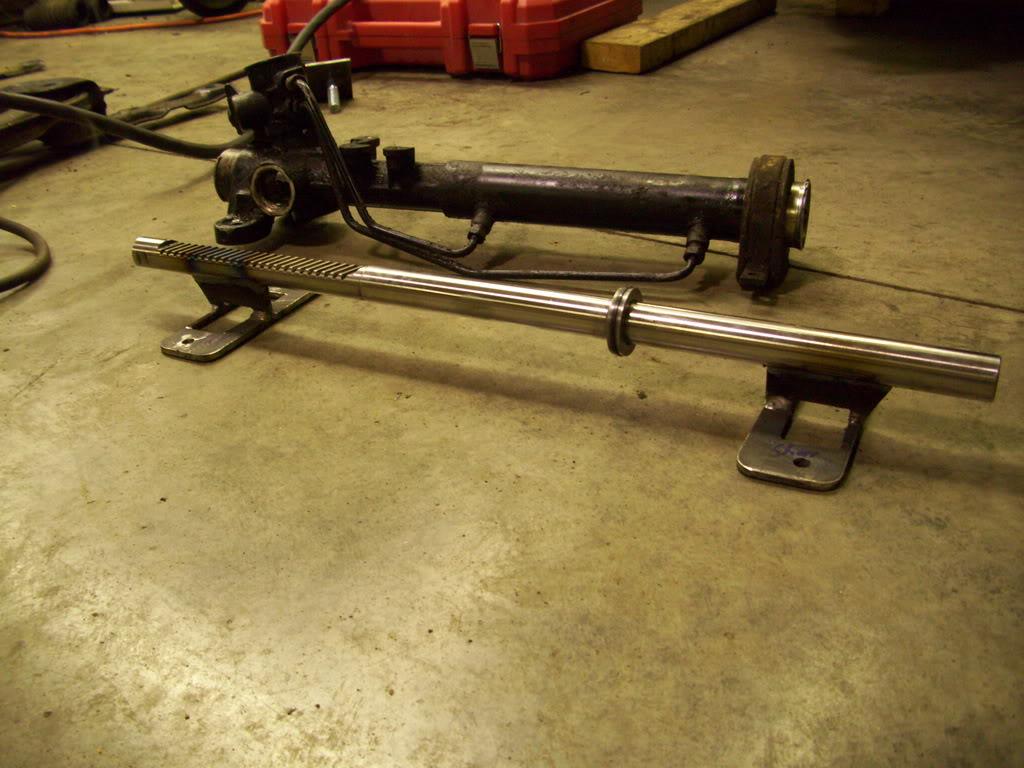
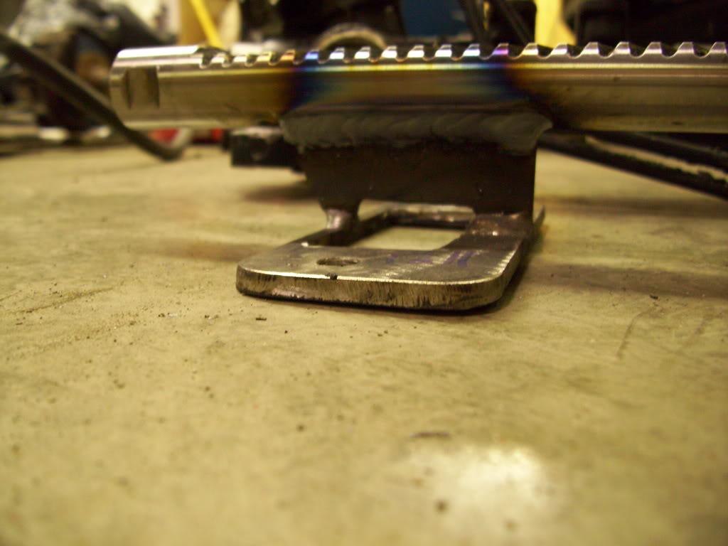
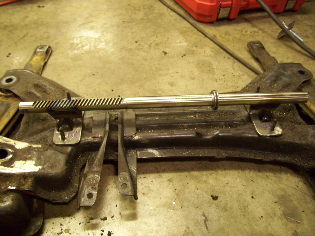
Don't worry, those were reinforced later. This was just to get everything in place without the bulky rack in my way.
I also did some more stripping under the rear seats so I could weld on the bottom side without contaminating the weld.
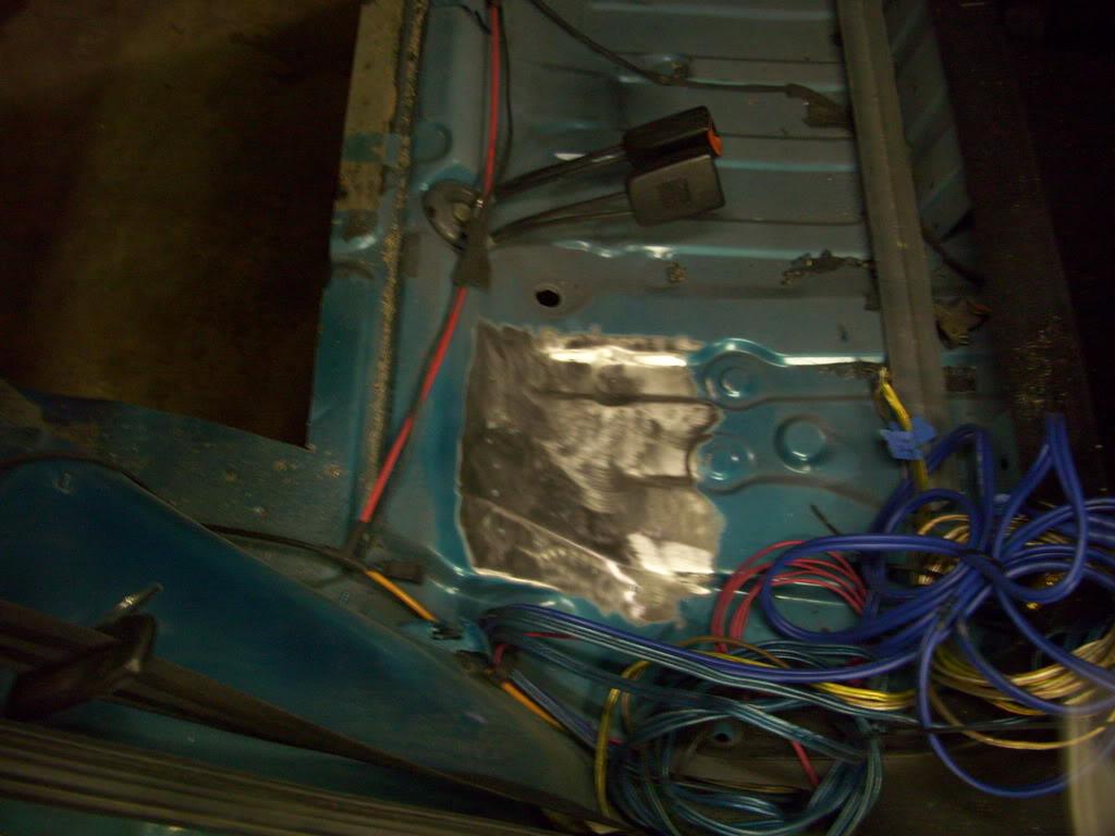
Feb 17, 2009
My buddy Chris (Stallion on vortex) comes over to help me get the axle centered in the arch. Chris is a very talented designer, he's the guy that does all the renderings you've seen of my car and others.
After a dozen trials, careful measurements, moving spotlights around, taking pictures and looking at the pictures, we decided the wheel needed to move forward quite a bit. I think we moved it forward 3/8" or perhaps more!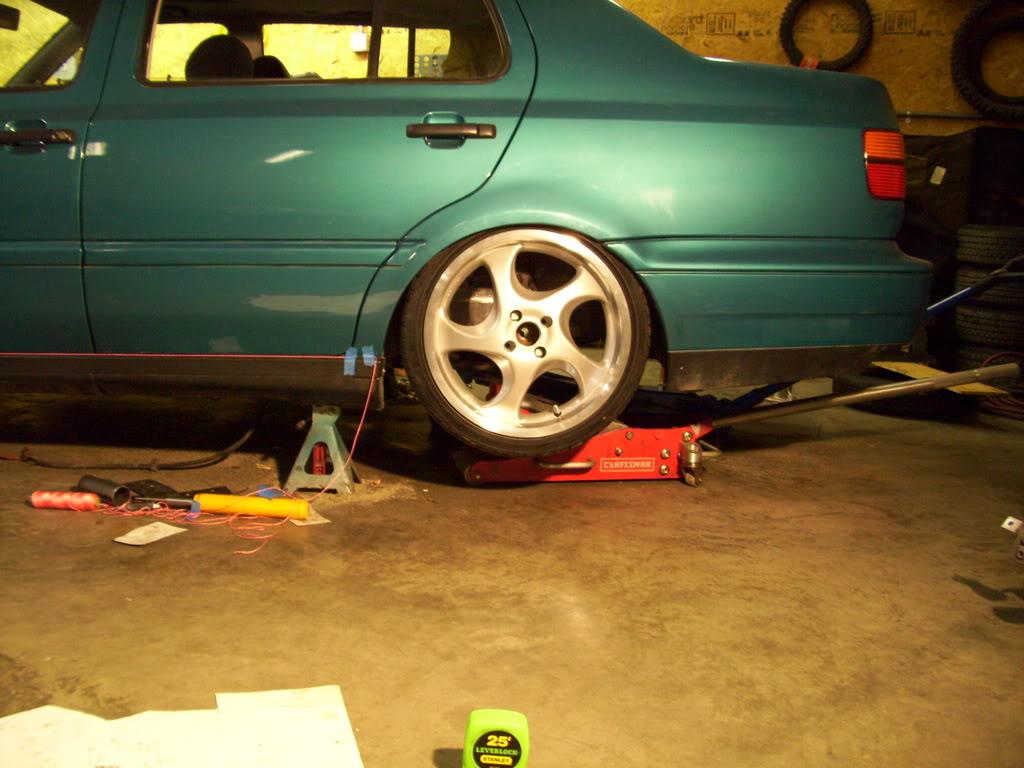
Feb 21, 2009
A few days later, I tack the subframe mounts in the new location using the string method again
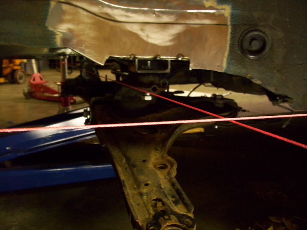
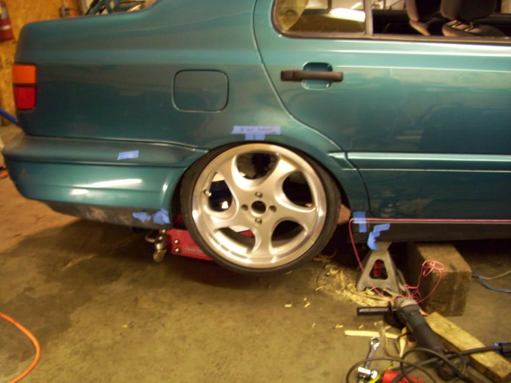
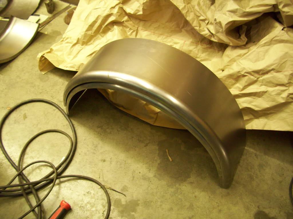
I also received new wheel tubs for the rear, this time from Tractor Supply. Yay rednecks!
Feb 23, 2009
This happened to the front arches too, but now that I have a camera (Thanks Santa!) I can take pictures of it.
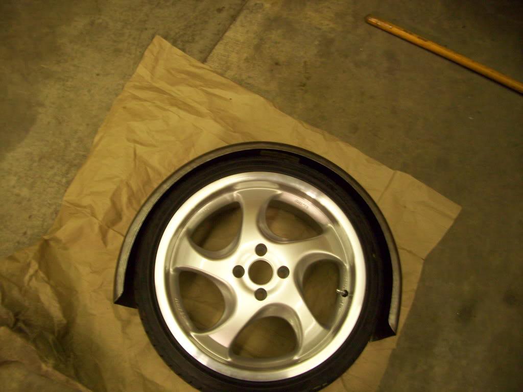
When I received the arches, the radius was sized for a much larger wheel.
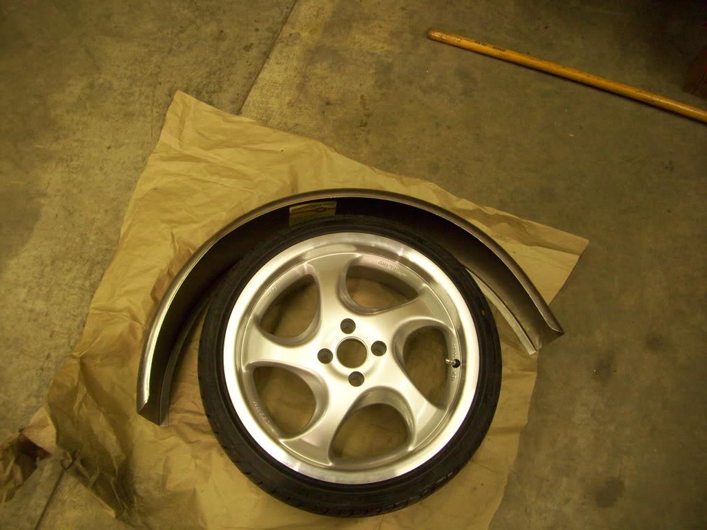
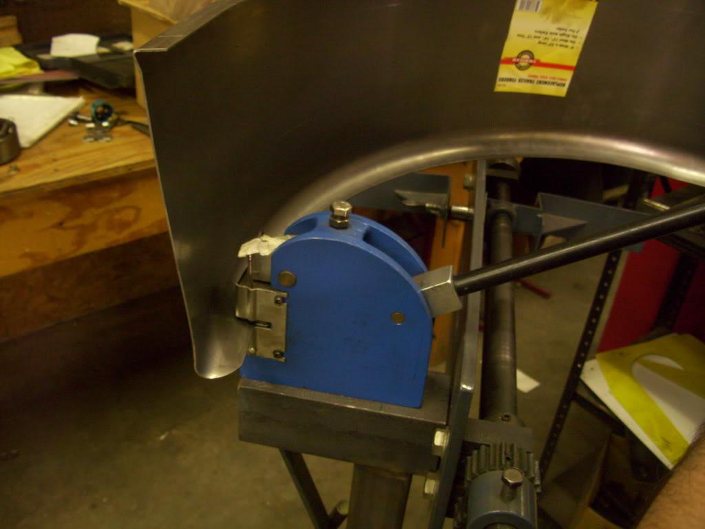
So I used a machine called a shrinker to tighten up the radius. It grips the edges of the formed fender and shrinks the metal, which pulls the whole thing into a tighter circle.
Much better!
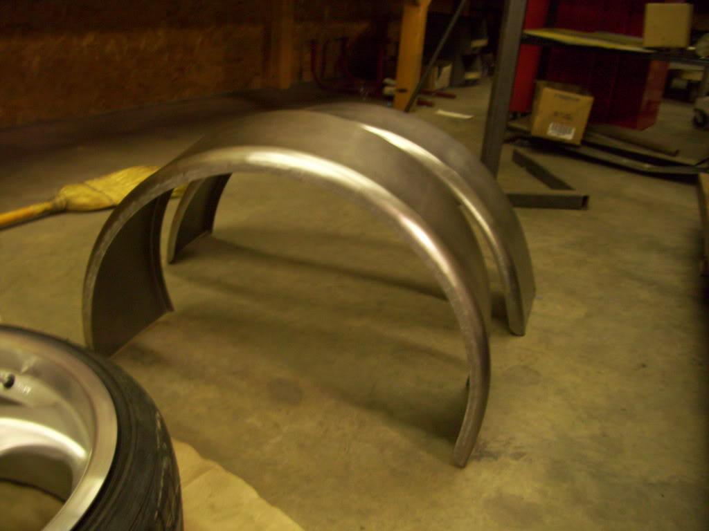
Comparison of standard and shrunken arch:
Feb 24, 2009
I got the subframe tacked in place and can start reinforcing the seat crossmember even further to take the suspension loads.
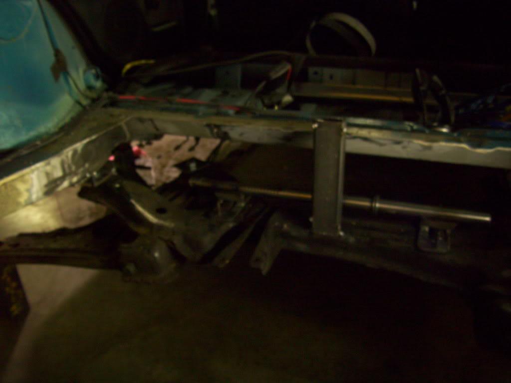
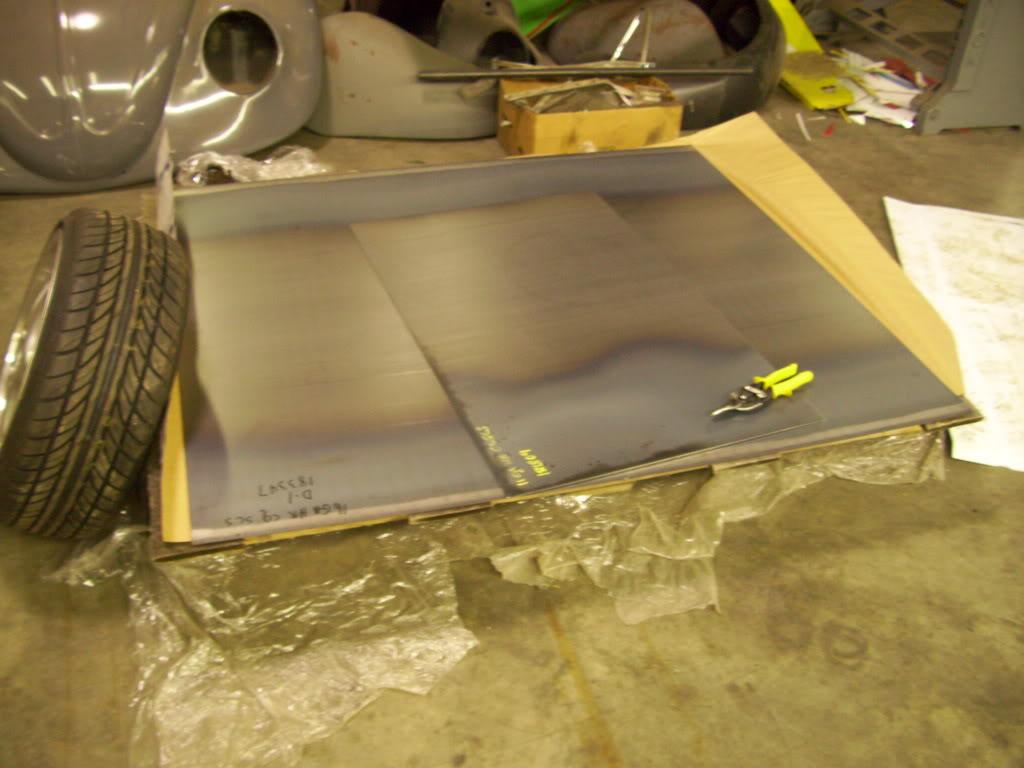
I got a big sheet of 16ga steel sheet for the trunk floor, and a plate of 1/8" steel to use for all the suspension mounts.
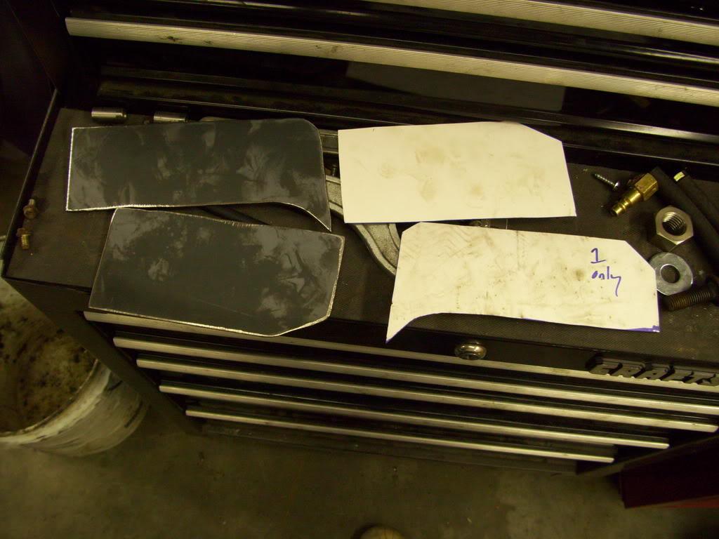
I made some templates and started fabbing up the supports for the rear seat crossmember/front suspension mounting points
Feb 26, 2009
I made a few more reinforcement pieces
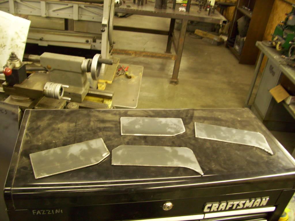
For the rear upper mounts, I planned to use camber plates. Before buying the actual pieces, I made these just for test-fit purposes.
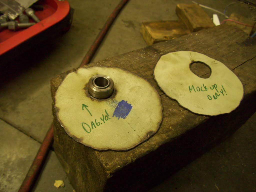
I noted the direction of negative camber so I wouldn't forget.Yo!
Feb 28, 2009
Just so nobody cruising the internet doesn't read and labels me a tard, I labeled them.
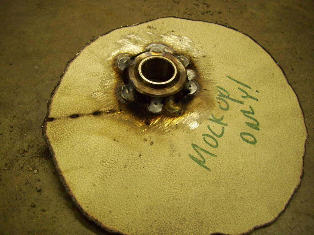
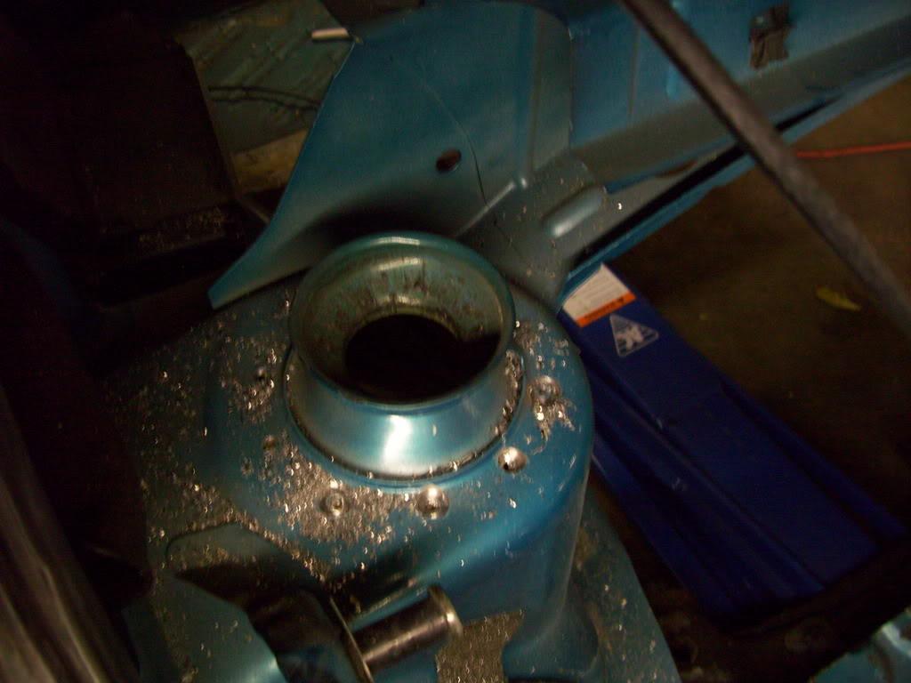
I started cutting out the upper rear mounts to fit the camber plates, but kept breaking drill bits and gave up for the evening
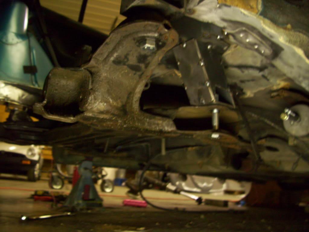
I started tacking up the forward mounting points of the suspension instead. You can see the reinforcement plates I added to the stock steel before welding the new mounts on, in effort to spread the load over a larger area of the stock structure and get the most strength and stiffness form the system
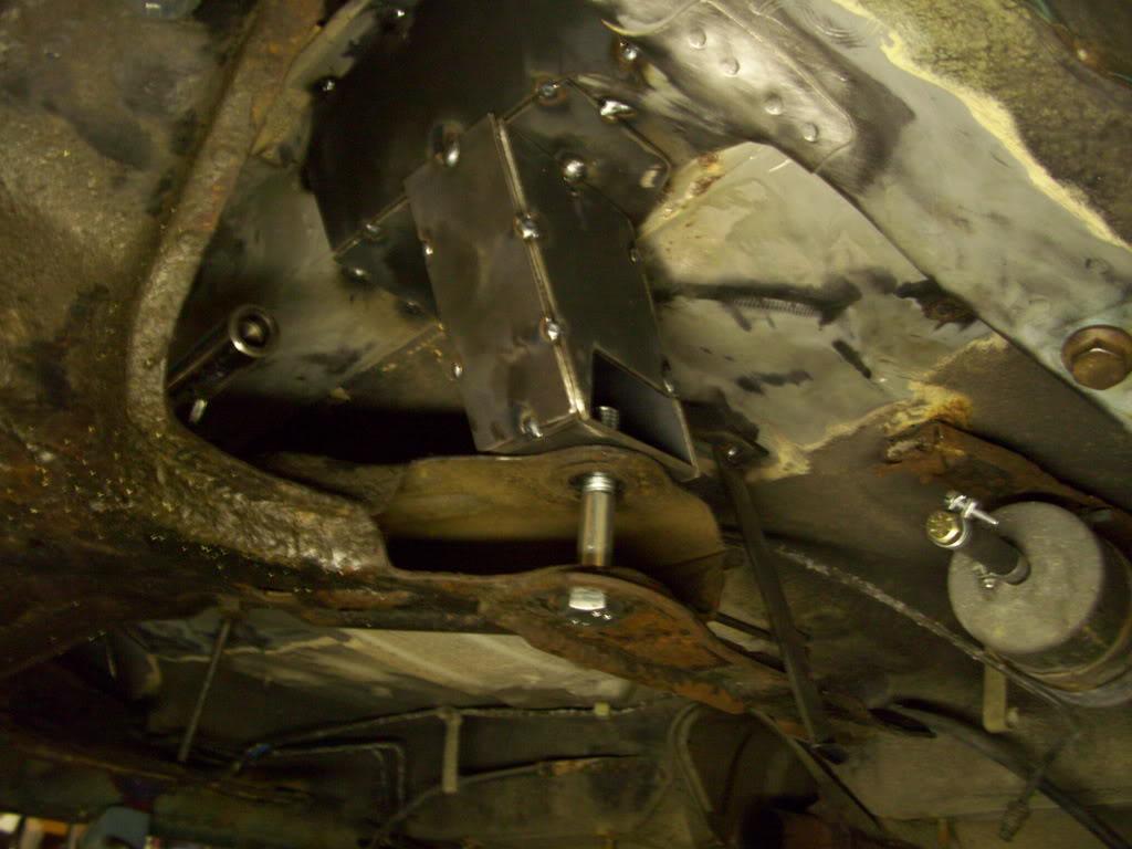
March 1, 2009
I took Paul Teutel's advice and used a step drill bit to remove the spot welds. They strictly use unibits on OCC for a reason - they cut really damn well! Made quick work of getting the old stock mounts out by drilling the spot welds.
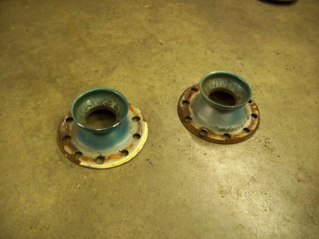
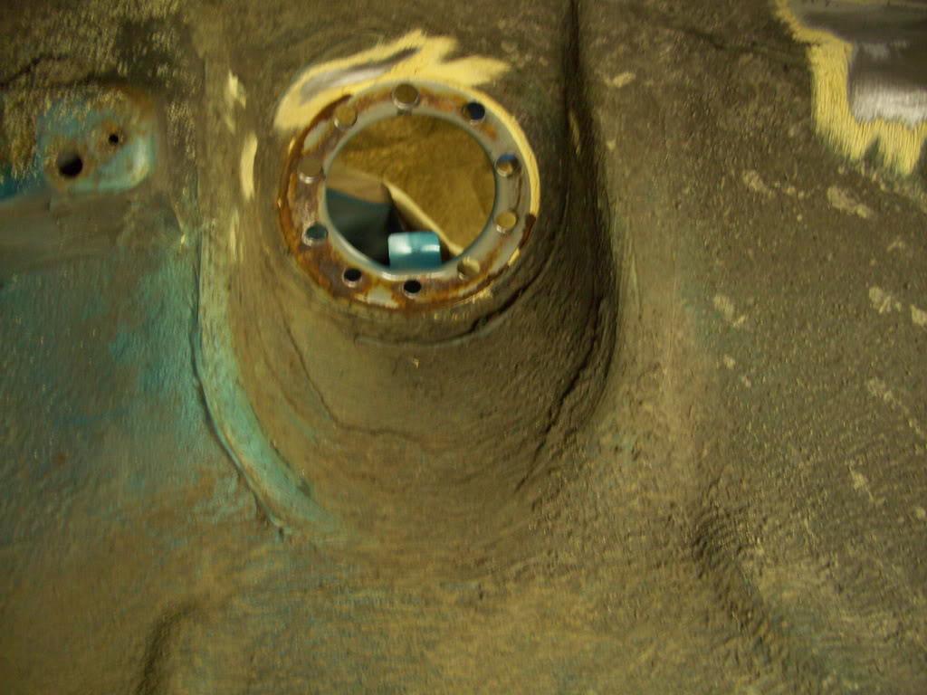
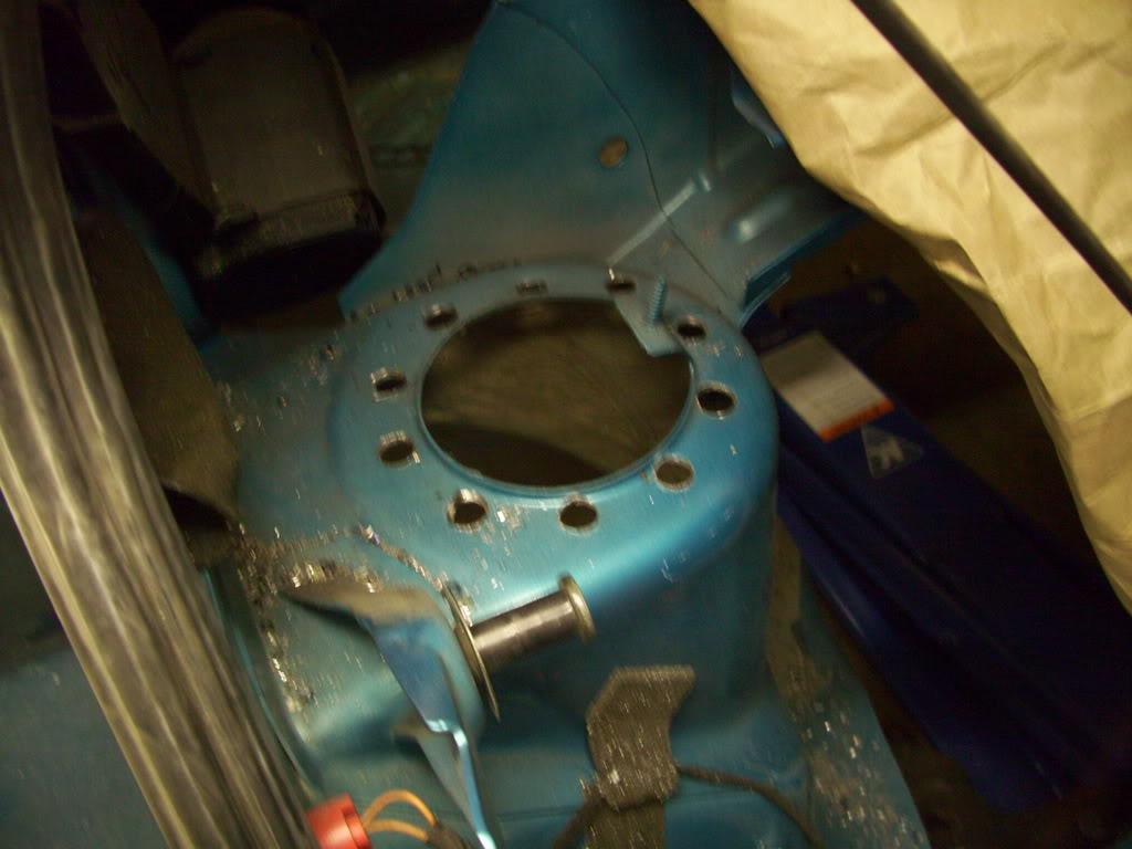
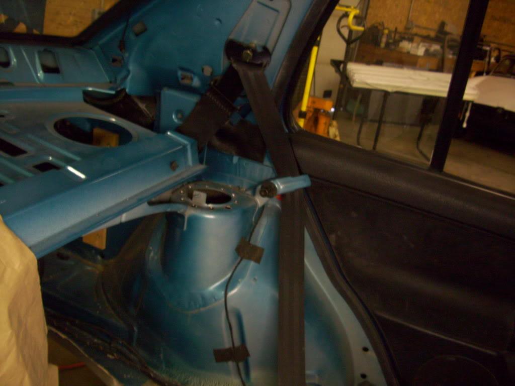
Now I have a clean flat area to mount the new camber plate upper rear mounts.
To be continued..
March 2, 2009
The first real test-fit.
I mounted up the rear camber plates to test the new struts and subframe location
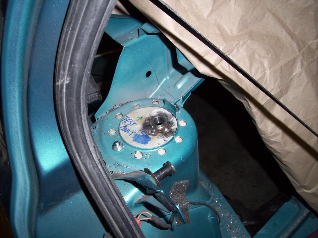
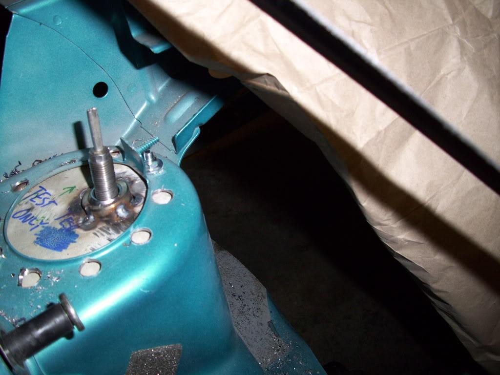
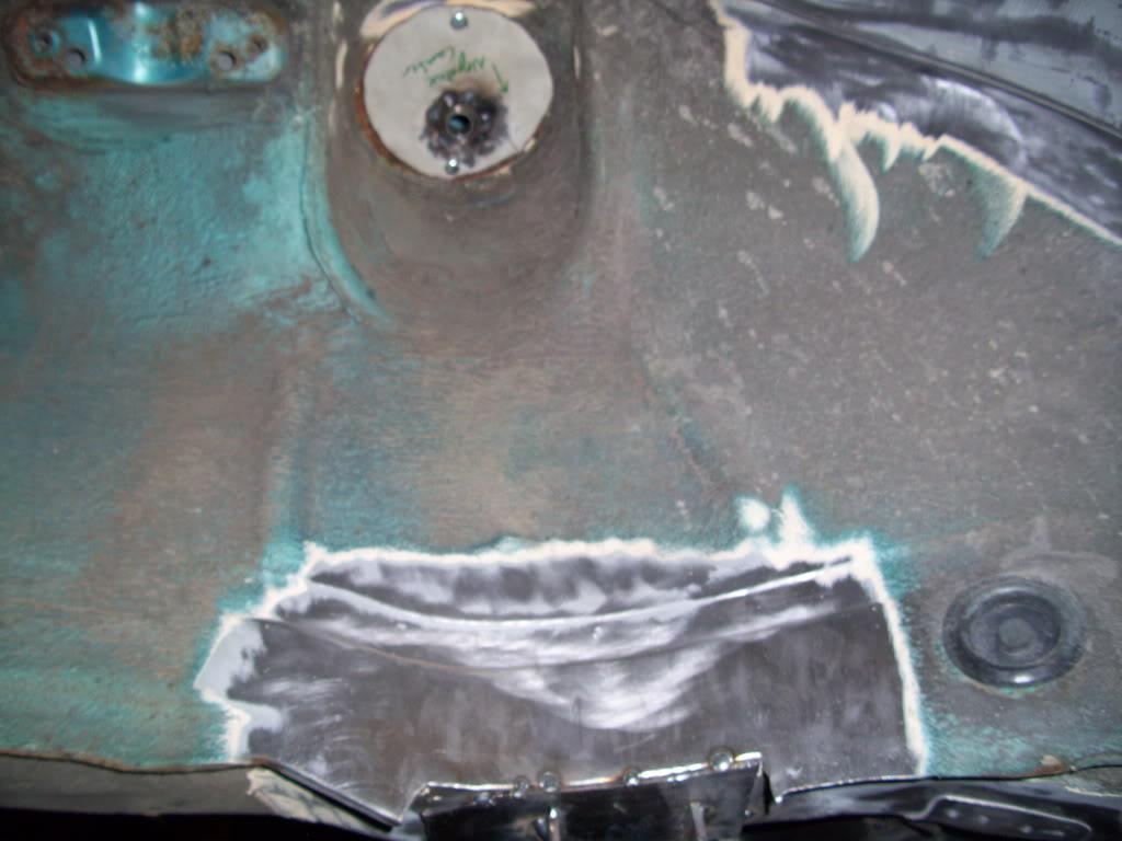
The wheel still rolls at this height!
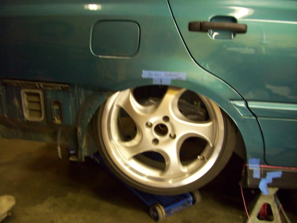
Now for the good part..
I bolted up all 4 wheels, all 4 struts, and laid the car on the ground. F*ck yes. Exactly as envisioned! Now I just need to finish it
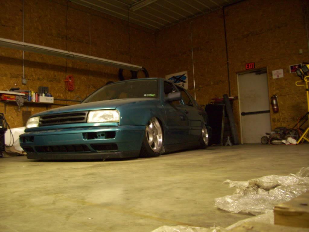
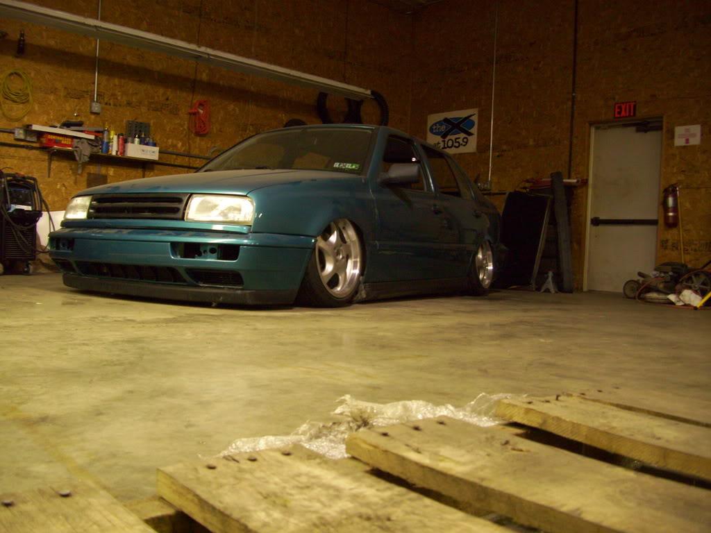
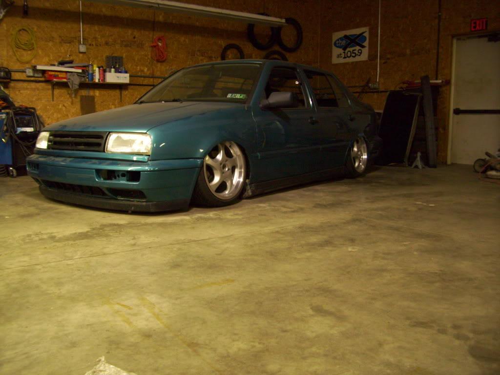
In this view the rear axle appears to need more forward motion, which I later added by moving the camber plates forward
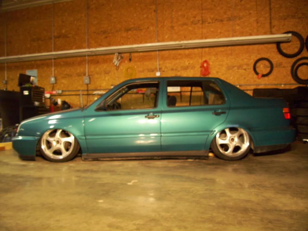
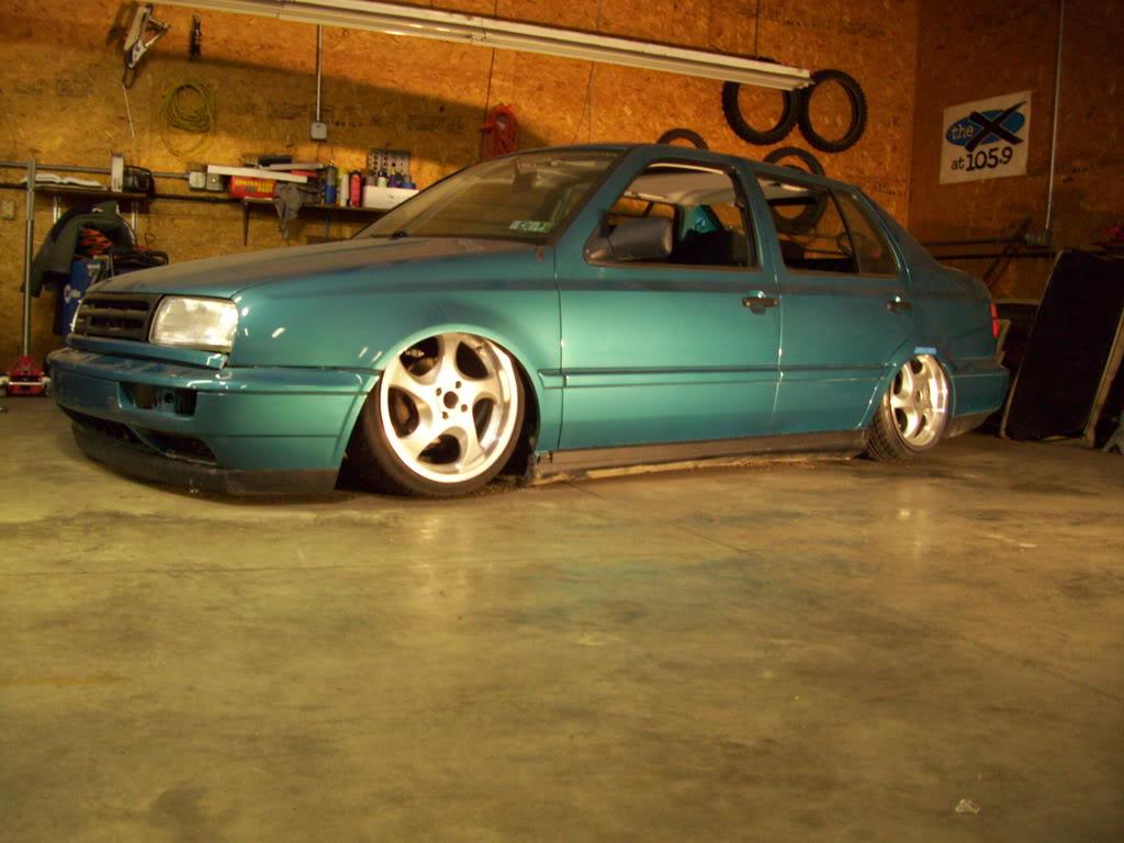
Still quite a bit of camber out back
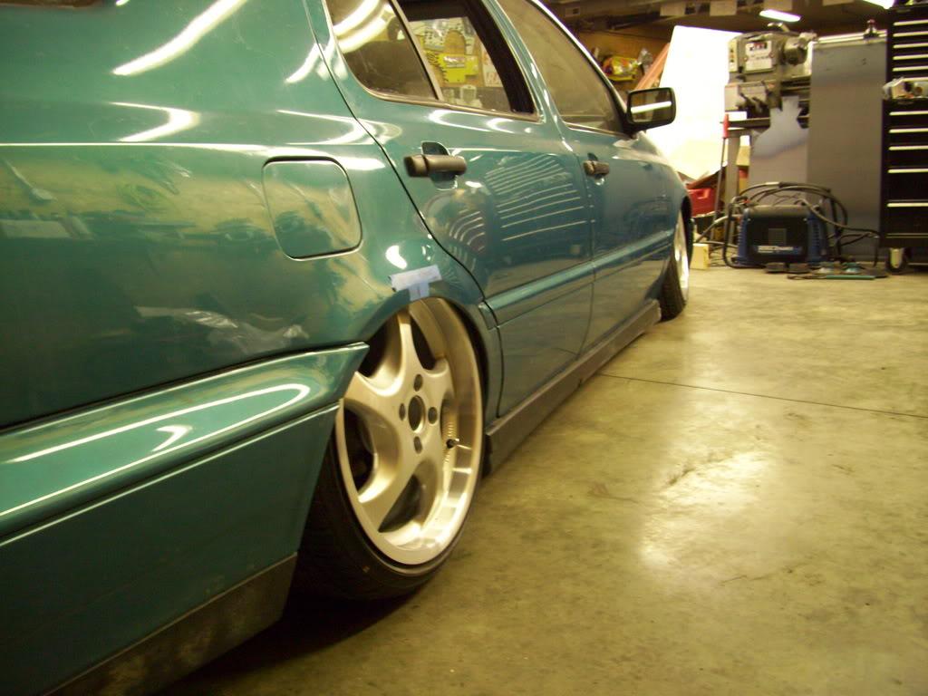
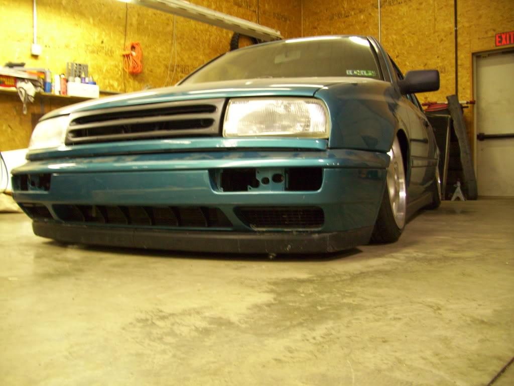
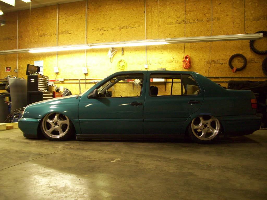
Mid march, I took a break to visit some friends in California, breh. I wasn't slacking; I was on vacation I met several friends from college, all huge car guys, in LA for 5 days of nothing. I got a tour of California Street Rods, saw the PPI R8, Toured both SpaceX and JPL (NASA), took a tour of the Fast and the Furious filming locations (Including Torretto's market and Dominic's house). We discussed things like drag coeffients, aerodynamic lift gradients (one friend is an aerodynamicist at GM), heat treatment qualities of exotic metals, the details of compex machined and cast light-alloy parts and multi-axis machining, (other friend is a rocket scientist), Formula SAE, lowrider jettas, Turbo S13s, overpriced hand tools, and girls. Well worth the time off!
March 18, 2009
I moved the rear axle forward a little further, another 1/8" further. After studying the pics for two weeks and thinking about it, I couldn't make it work with moving the camber plates.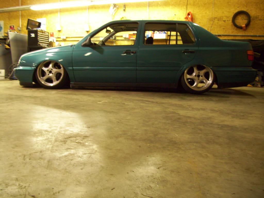
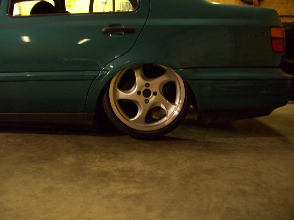
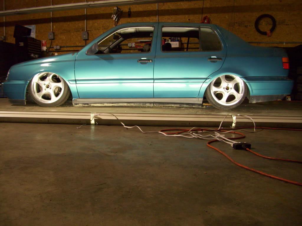
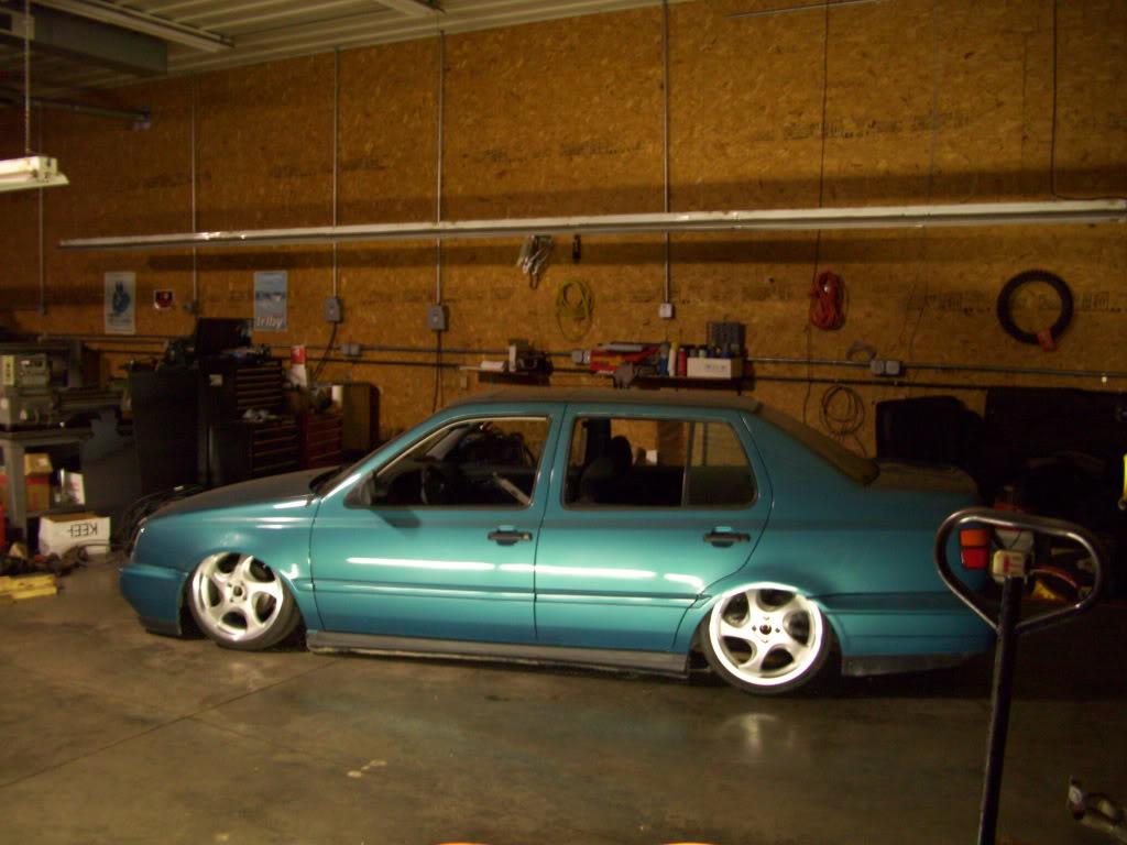
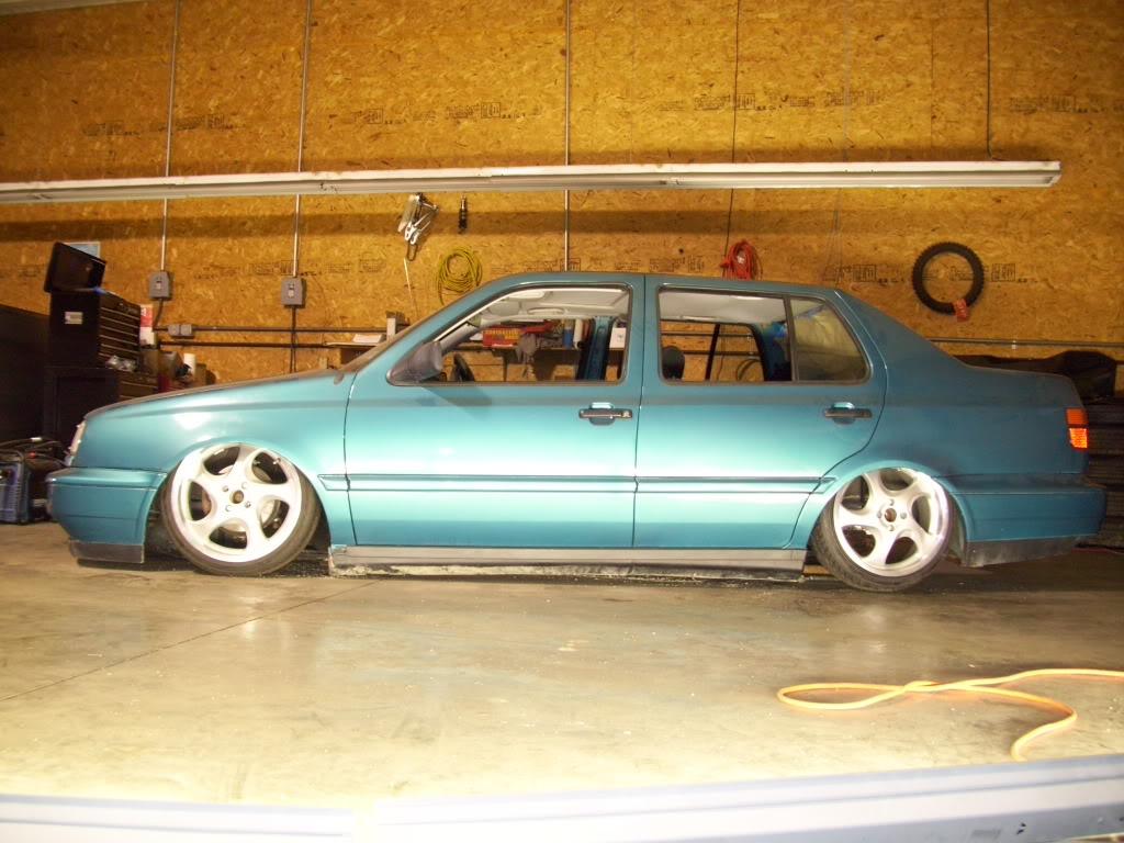
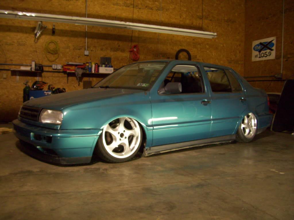
March 22, 2009
I cleaned up the cuts in the rear inner arches, in preparation for welding in the new wheel tubs.
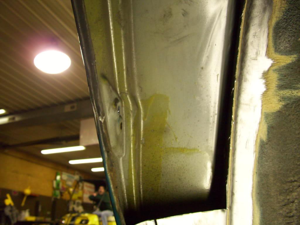
Here the bottom of the door latch striker would be one of the limits of low, so I needed to trim it.
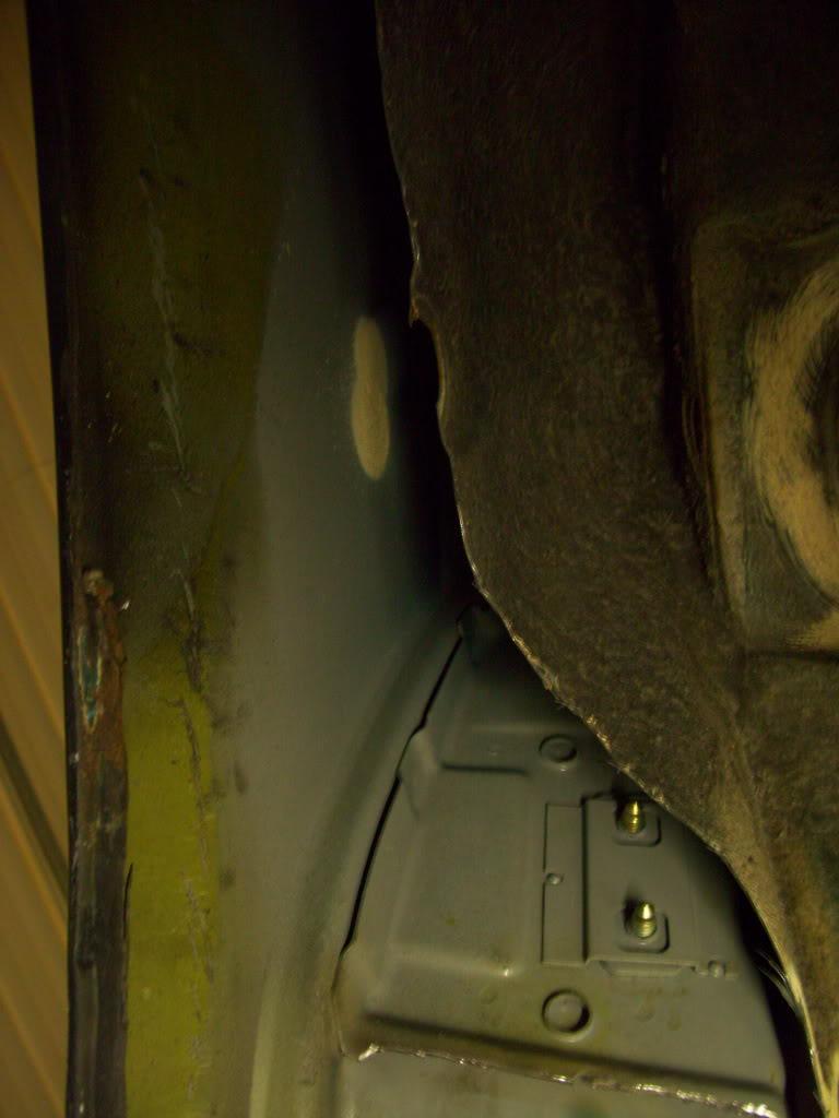
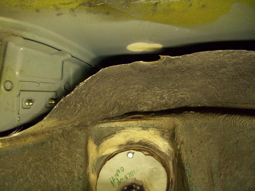
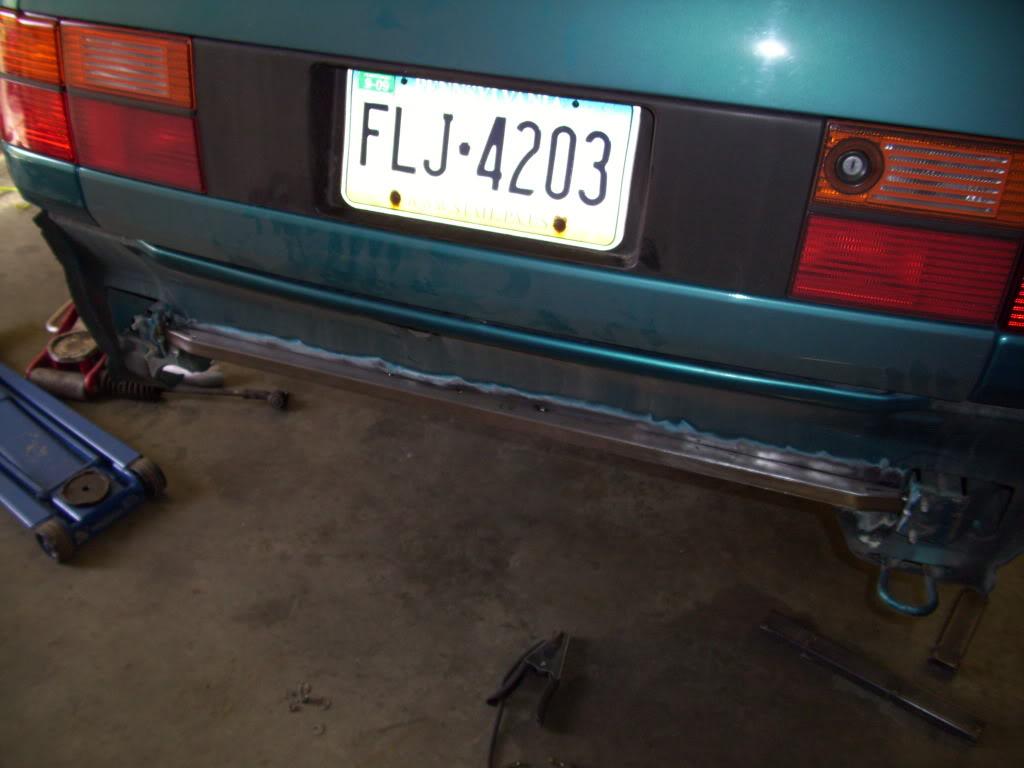
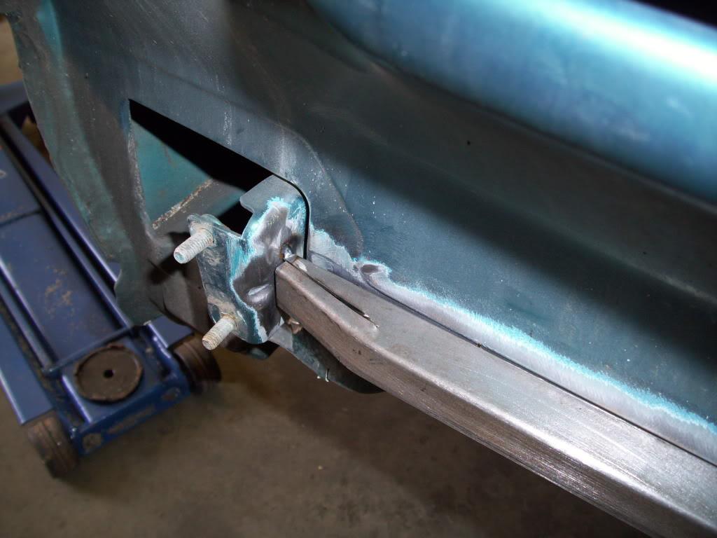
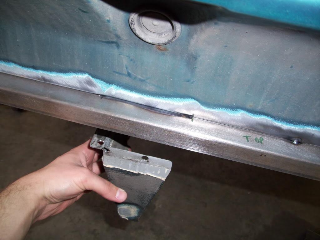
I had to cut out the rear quarter panel under the bumper to get the wheel close enough to the rear bumper, that way I could run a more aggressive offset.
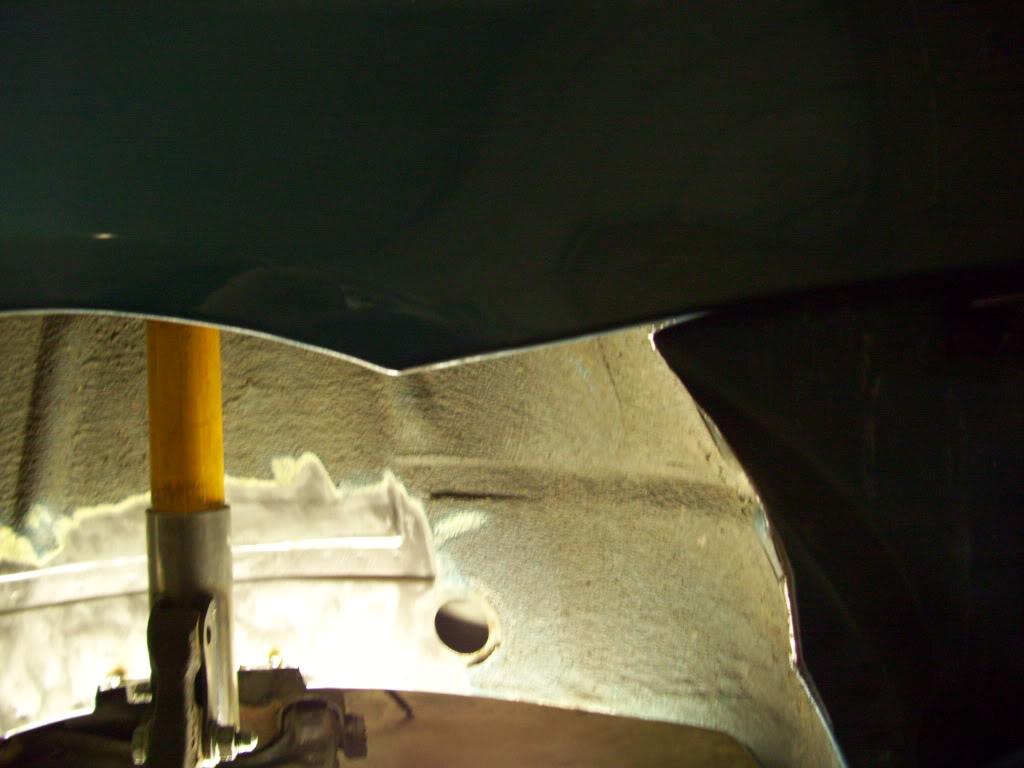
I trimmed the bumper to match too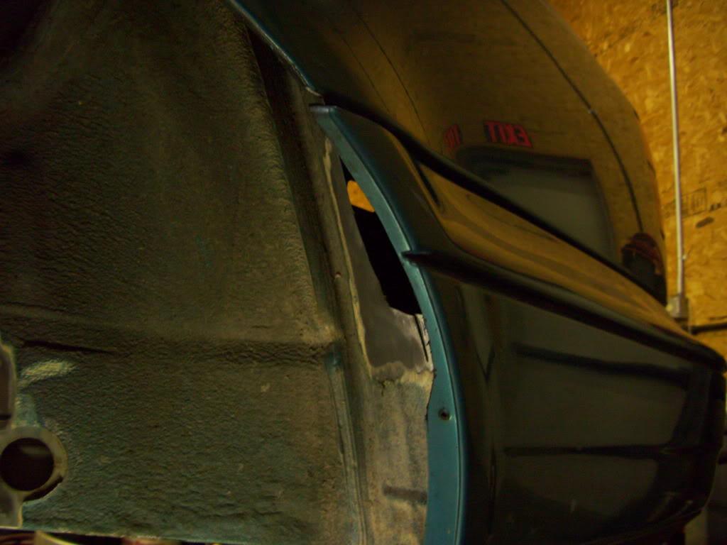
March 28, 2009
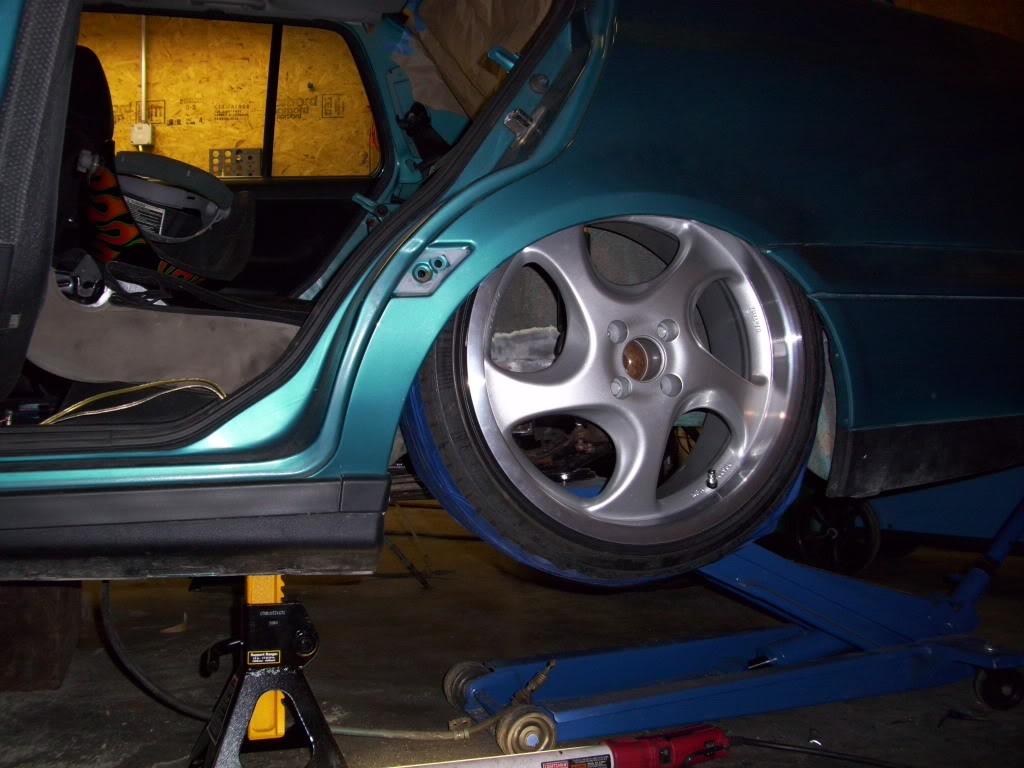
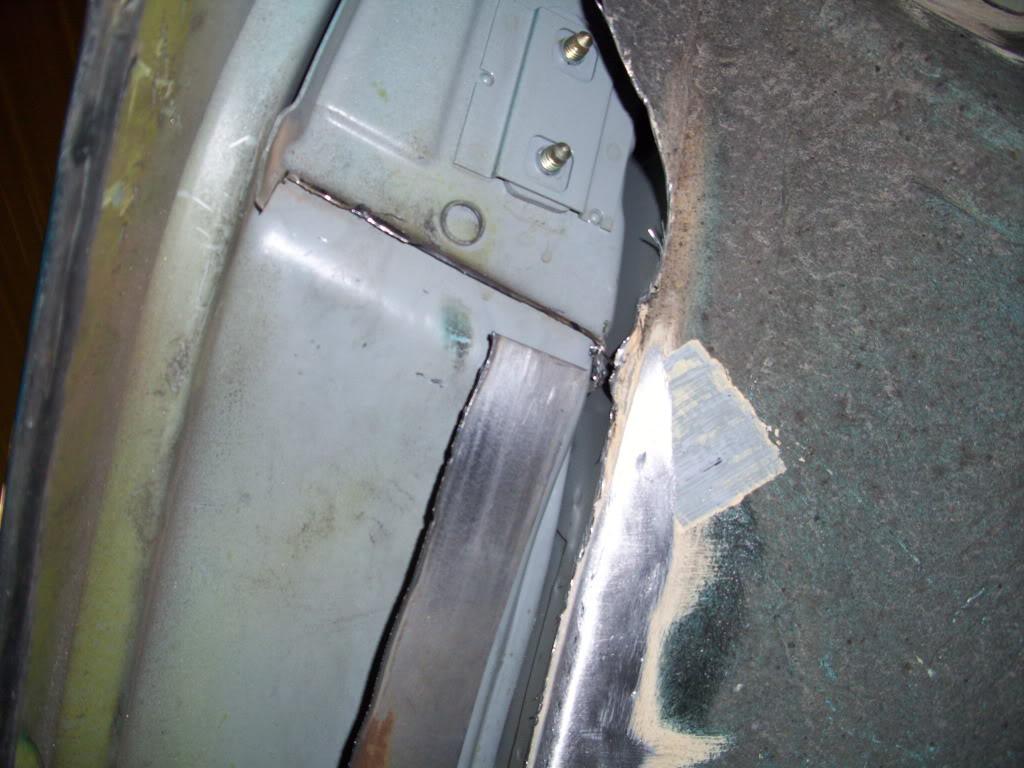
I looked into the possibility of tubbing through the door. After some careful consideration and some more test-fits, I determined I could do it if I wanted but it wouldn't be necessary. I wanted to avoid this to maintain as stock of an appearance as I could
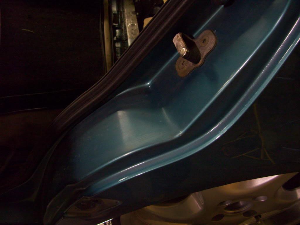
Trimmed the latch plate even further
Here the potential clearance issues are pretty clear!
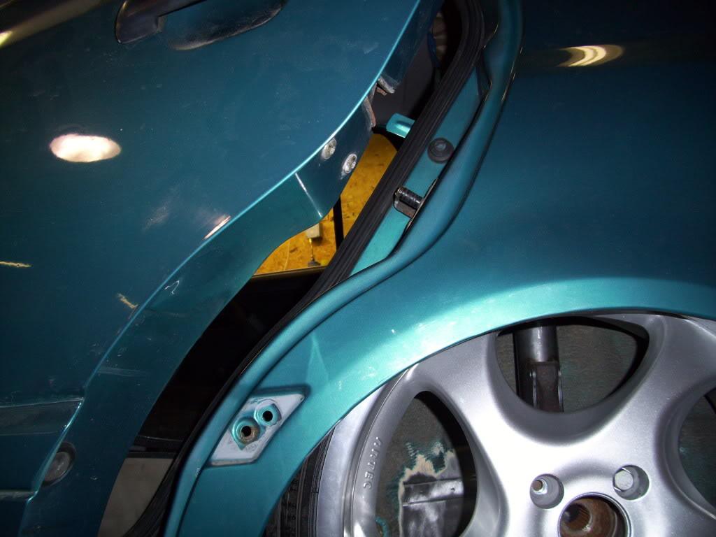
I can still get plenty of reverse rake without cutting into the door, so I decided not to .
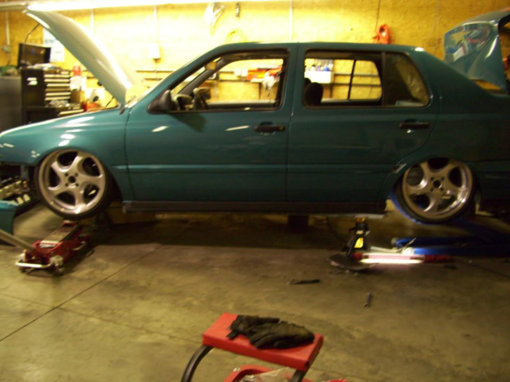
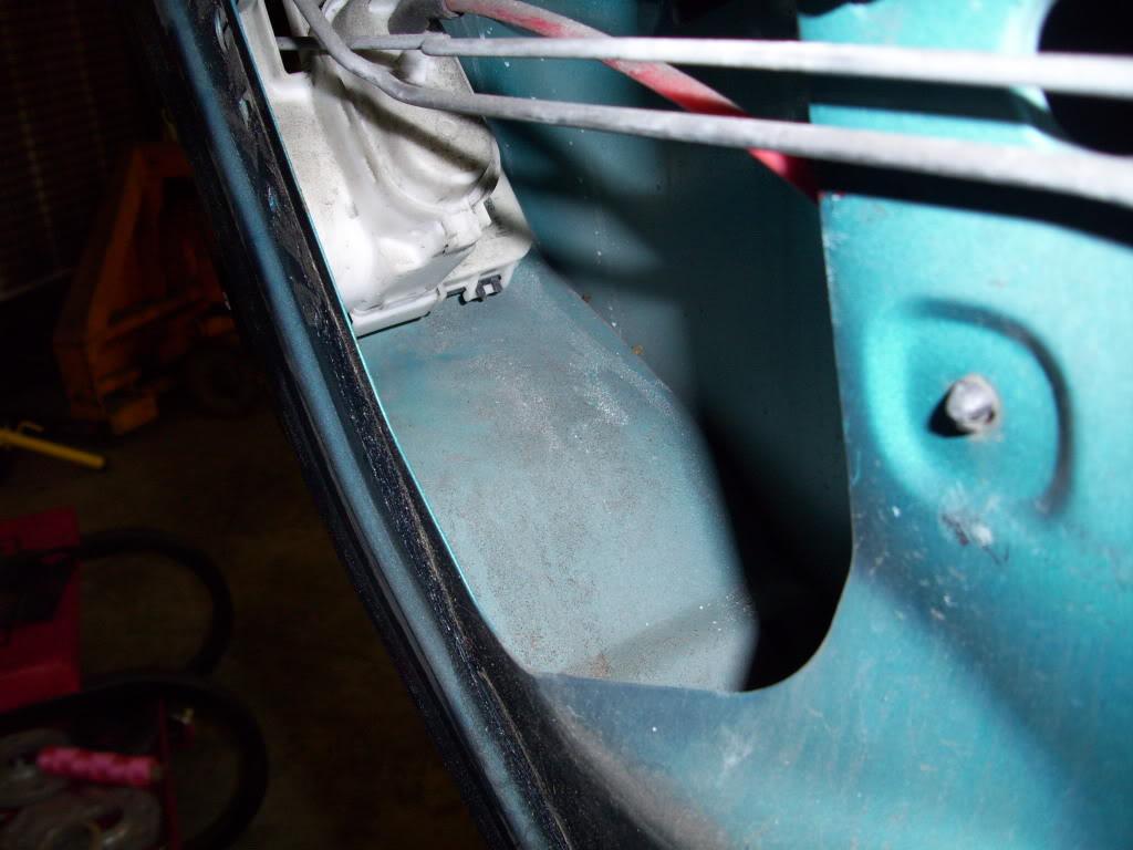
But I took some pics of the inside of the door, just in case I wanted to cut it
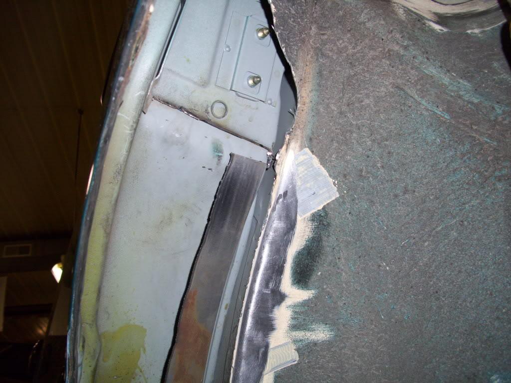
I added a piece of steel to simulate the wheel tub while doing the test-fits. This made sure the tire wasn't resting between two tread blocks and getting me a little lower than would be otherwise possible once the tubs were welded in.
April 1, 2009
Holy hell, this was a weeknight?!? I must have been up late or super motivated or something lol. I have like 30 pics from this day.
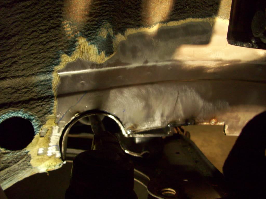
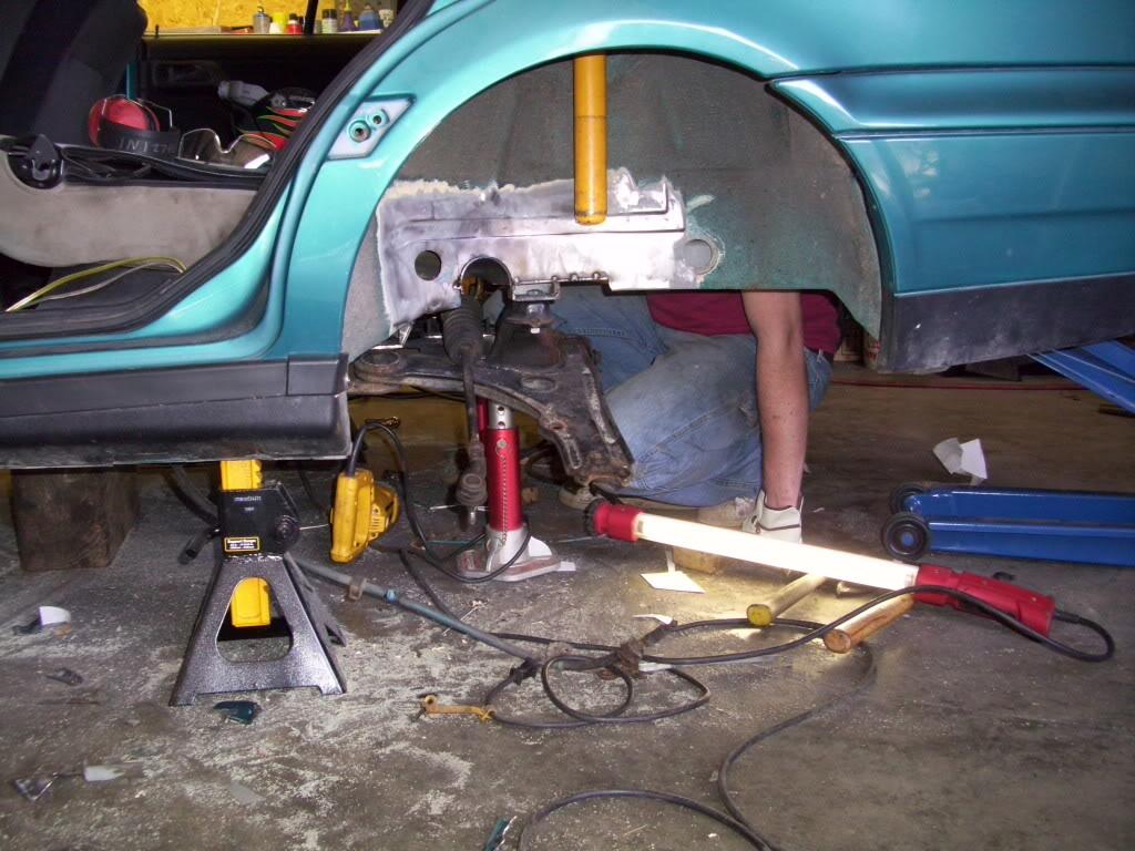
I began notching the rear frame rails for the rear tie rods.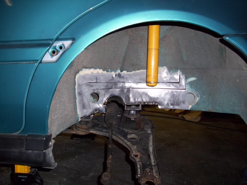
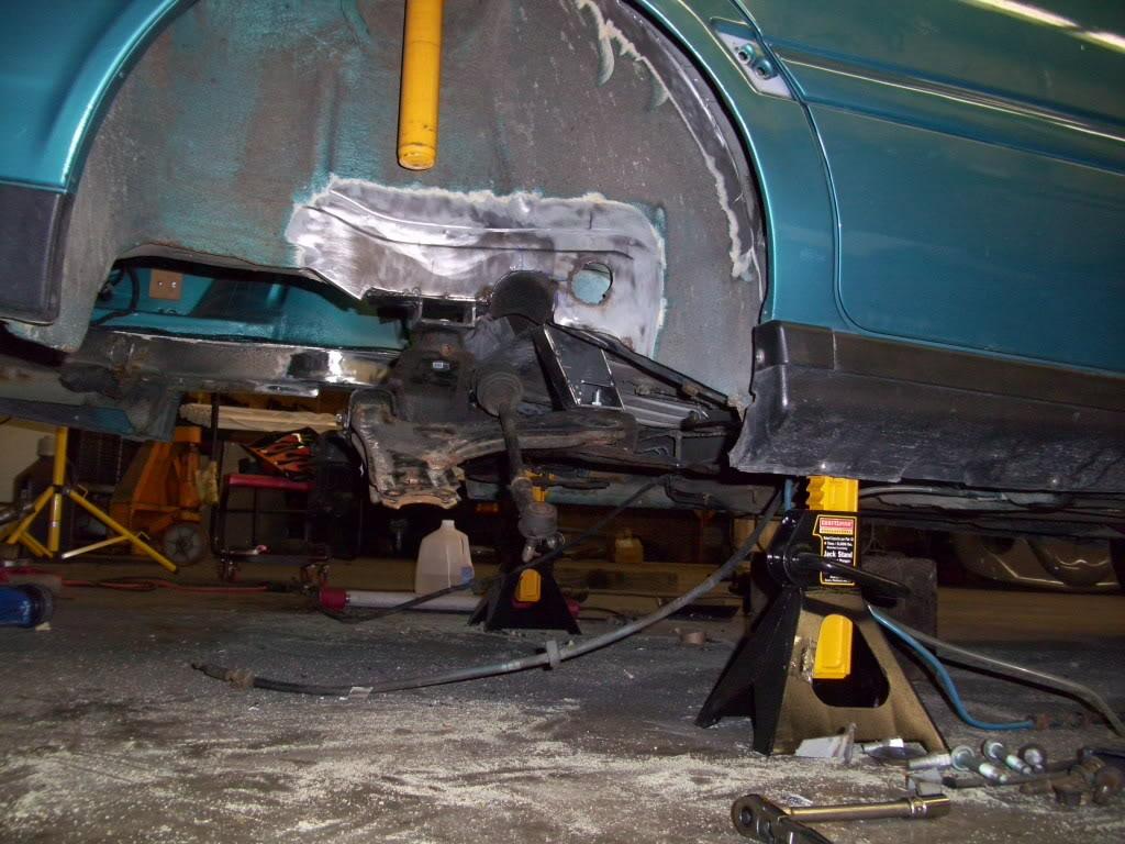
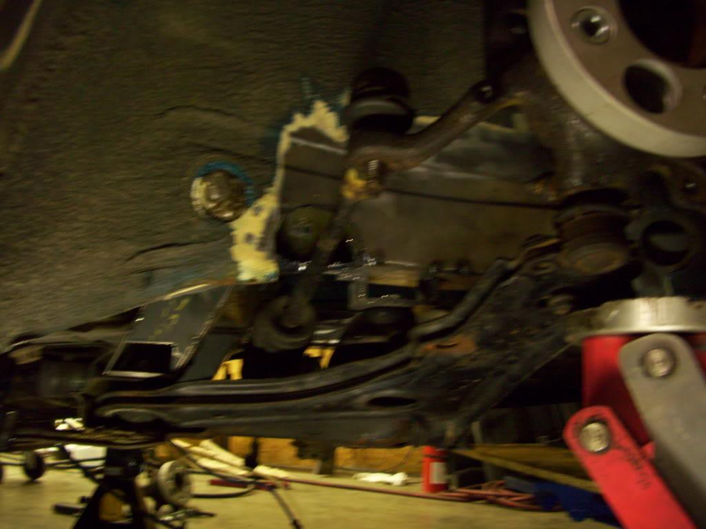
I welded in a piece of 1/8" thick 3" diameter steel tubing.
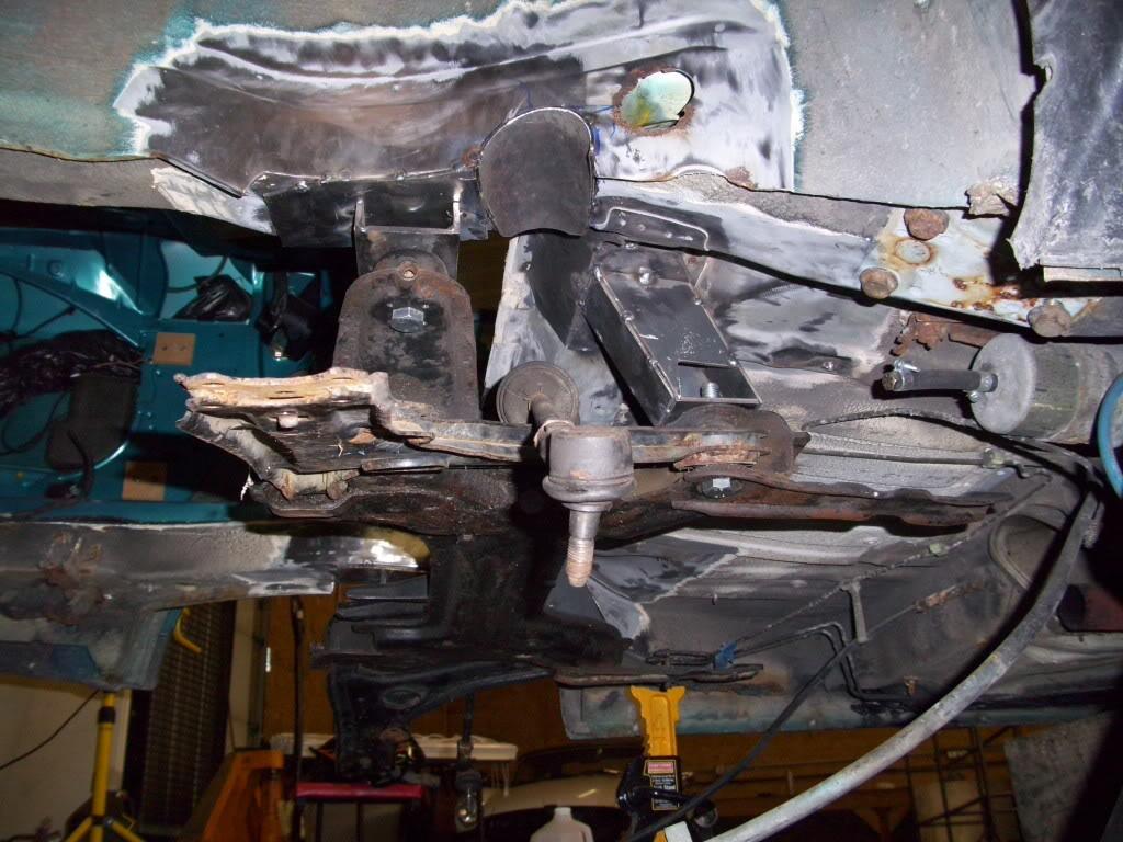
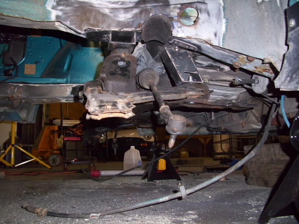
You can see the notch angles quite a bit, to match the angle of the tie rod. Rather than cut straight through the frame rail, and weeken it greatly, I cut the notch at an angle to maintain as much thickness in the frame rail as possible.
Tube tacked in
Lots of clearance, and the angle was perfect.
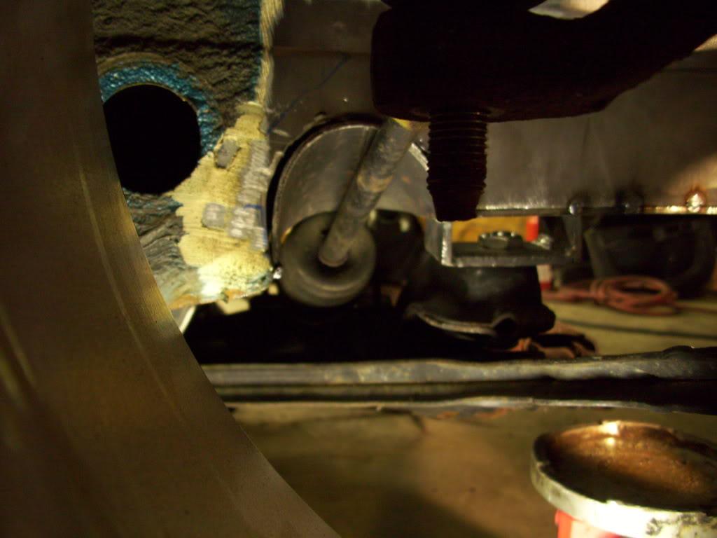
With the spindle on and tie rod bolted in place
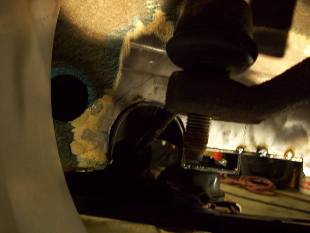
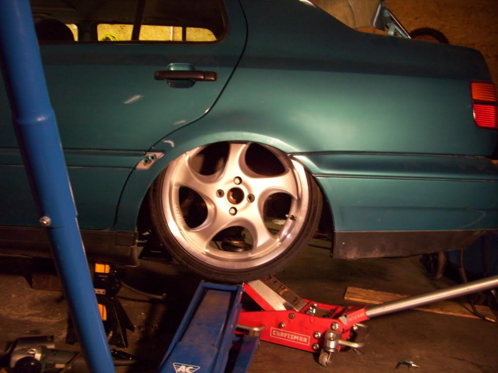
Wheel, now fully in control by the tie rods and control arms and camber plates! No more just setting it up on the jack.
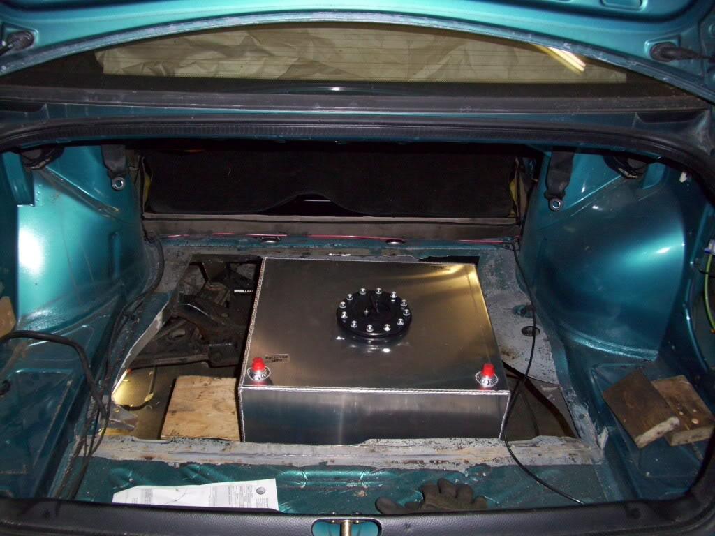
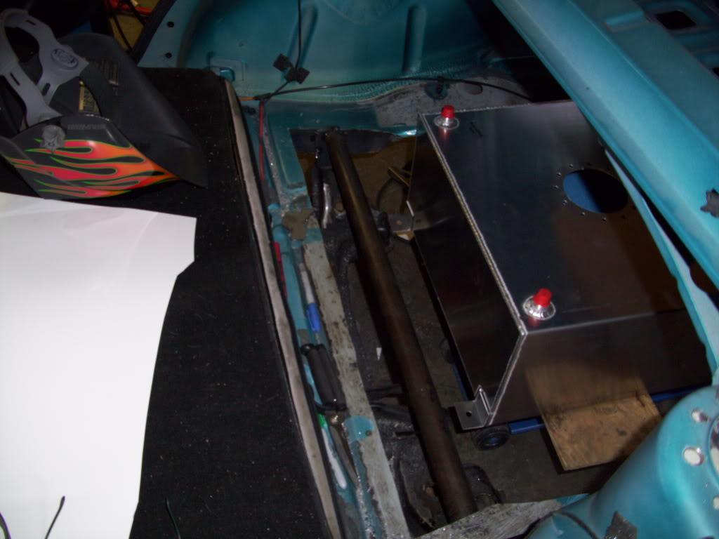
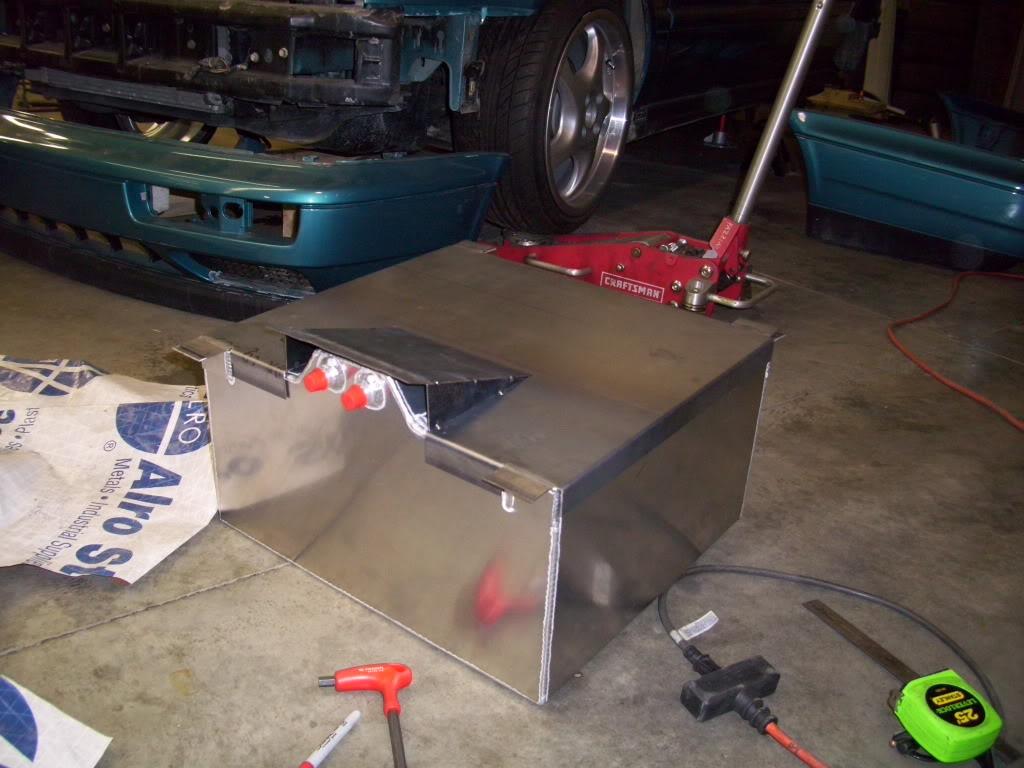
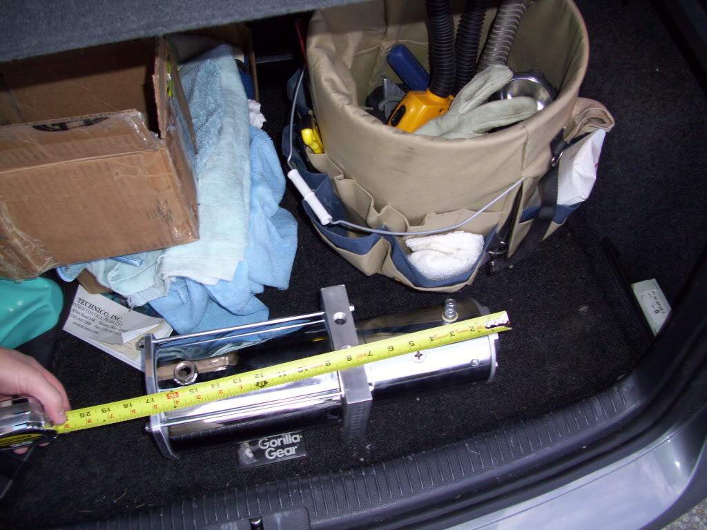
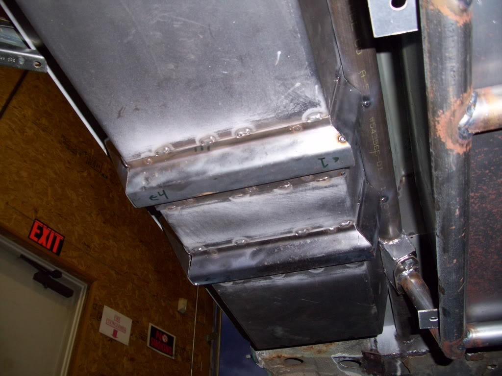
Since I had to replace the stock fuel tank, I bought a rectangular aluminum fuel cell from Summit. I set it in place to check the rough positioning.
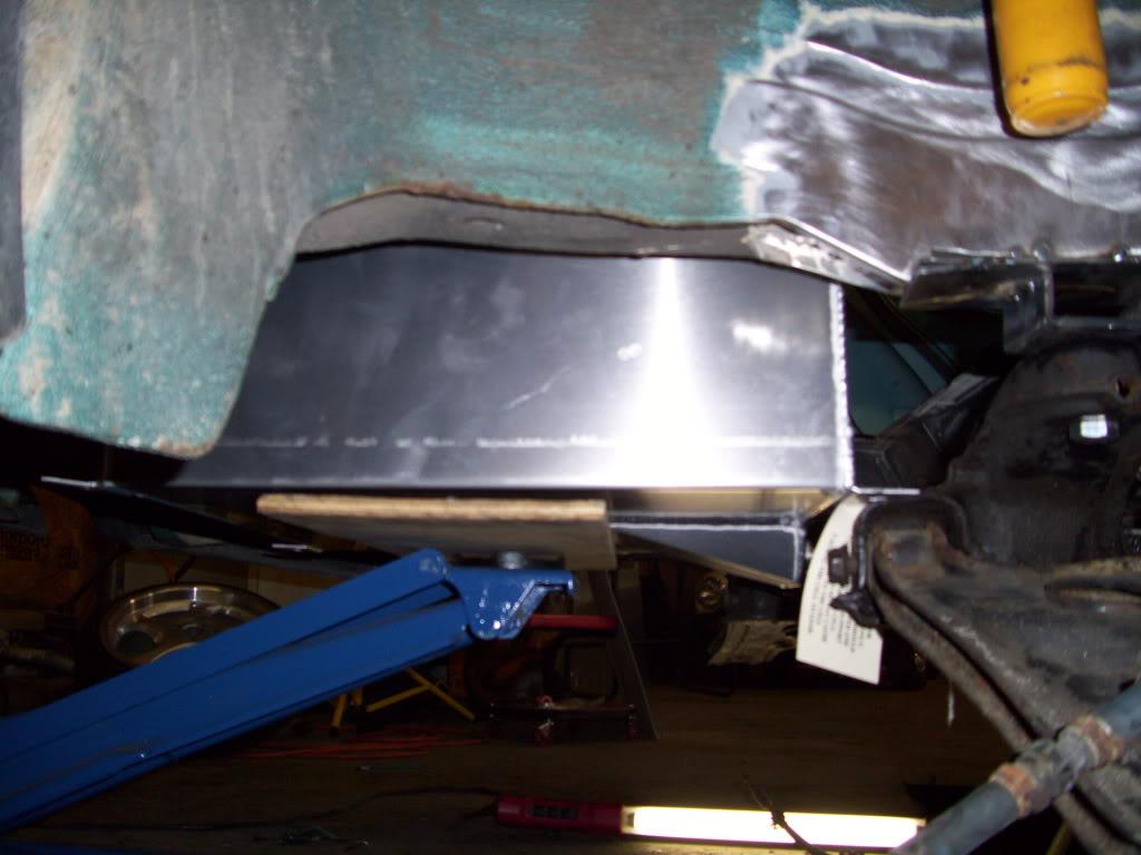
I labeled this pic 'Cut and paste' in my photobucket lol. Basically what needs to happen! I planned to use the stock pump mounted down inside the cell, so I needed to bond the stock supply/return/electrical connections into the lid of the fuel cell
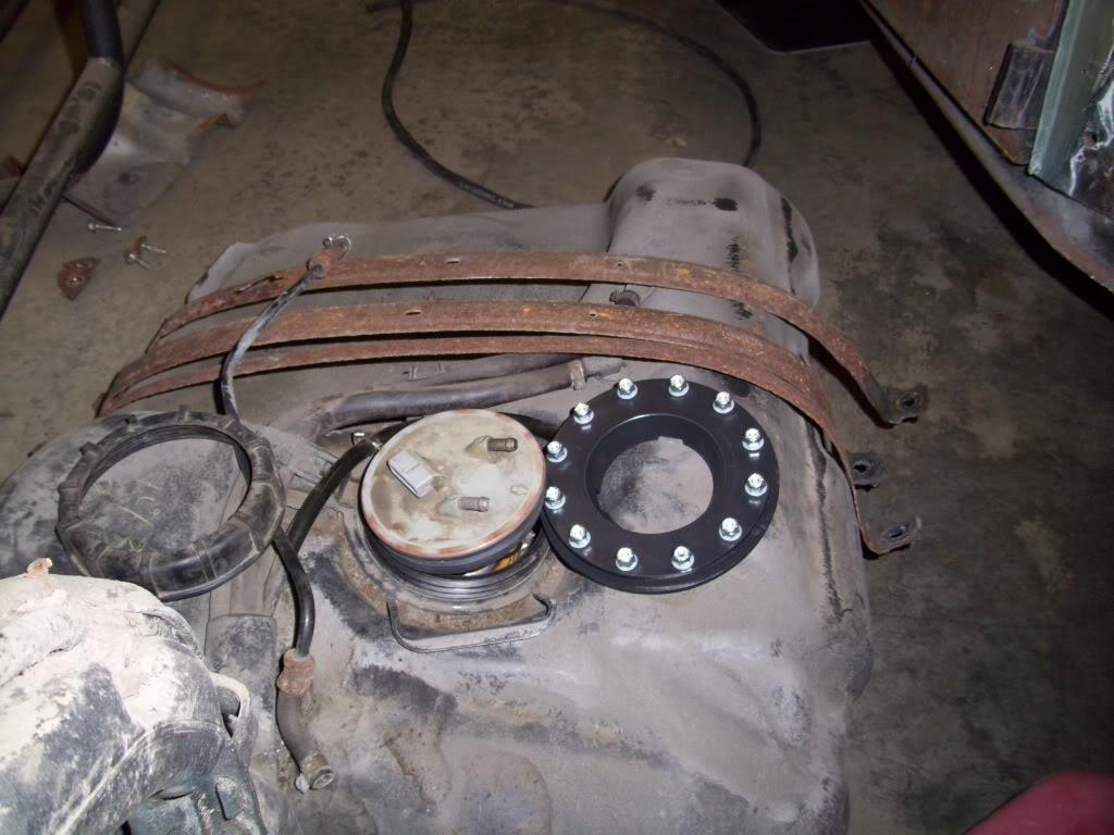
Now the details of the fuel cell...
I planned to keep all the fuel below the trunk metal, and all the hydraulic stuff above. The hydraulic motors are electric, and can sometimes spark - even during normal operation. Sparks + gas tank in a small trunk = mega explosions, so I needed to separate the two. I decided to keep the gas down, which is also out of hte passenger compartment. This requires a full floor over the top of the cell, a custom fillerneck somewhere completely outside the body, and some custom plumbing. Add it to the "To Do" List!
I must have had a friend stop by and take some pictures of me working.
This pic just looks weird lol
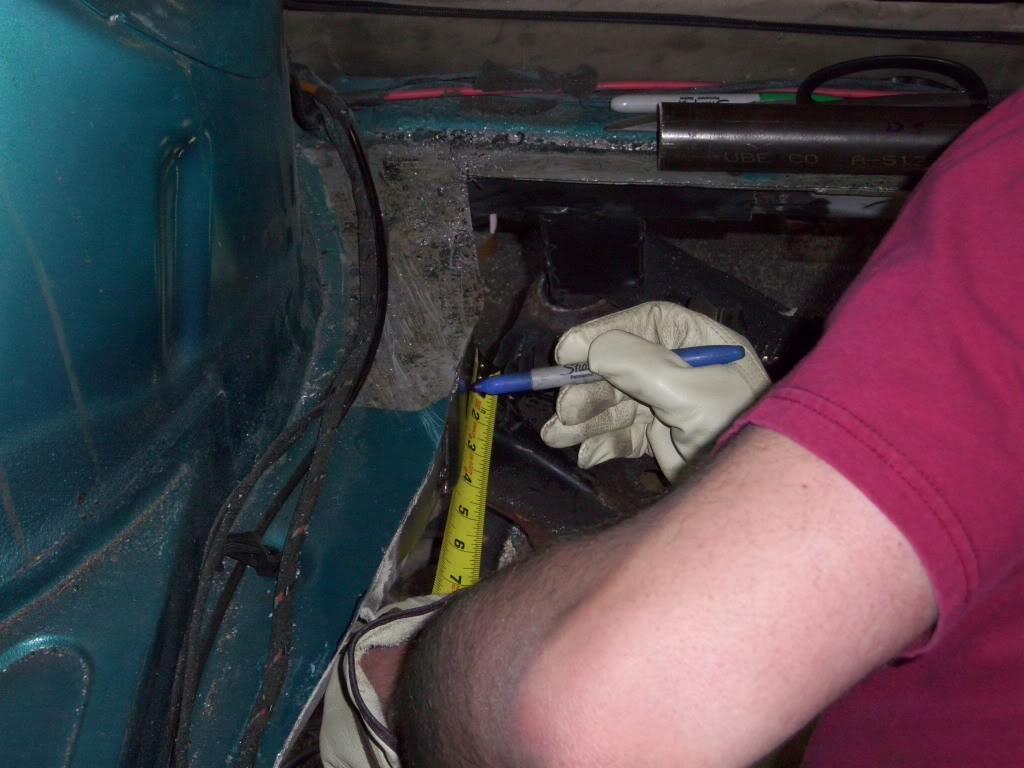
Measure twice, cut....well... like three dozen times
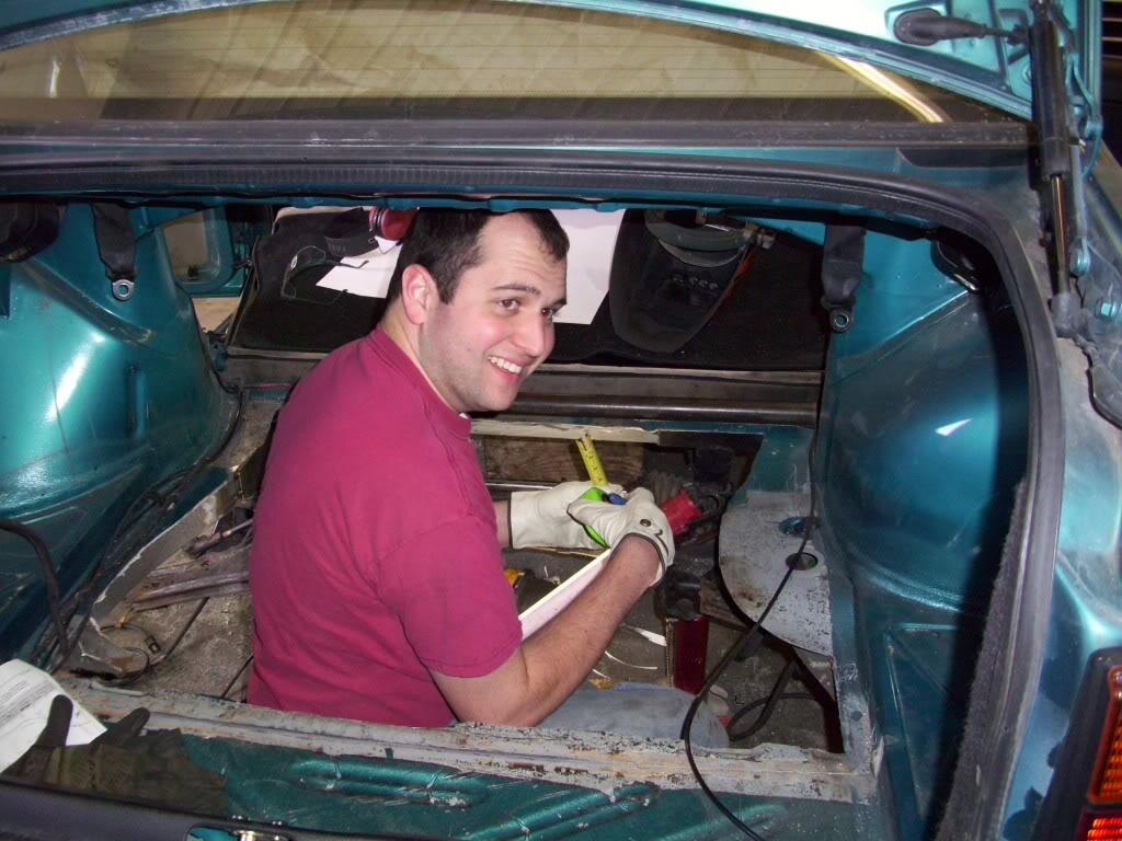
I look like a ratard.
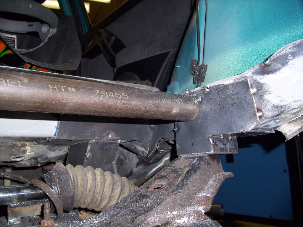
I welded the first crossmember into place, as well as a bunch of reinforcements around the subframe mounts. I wanted this area to be the strongest on the car, since it would be taking all the rear suspension loads.
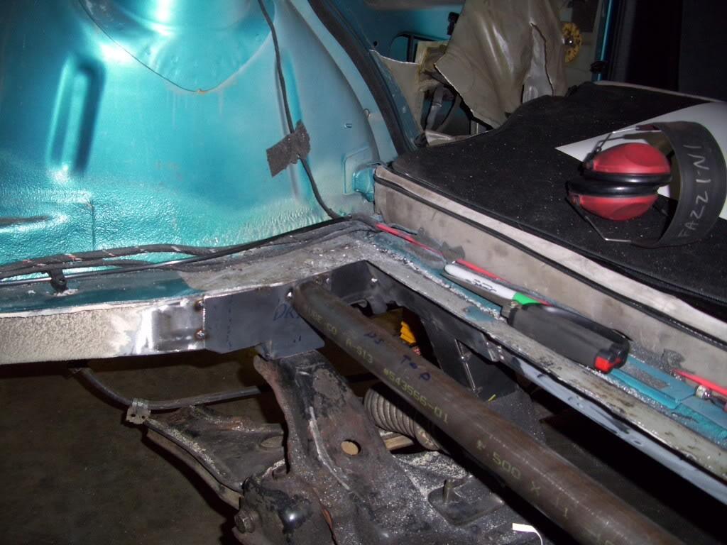
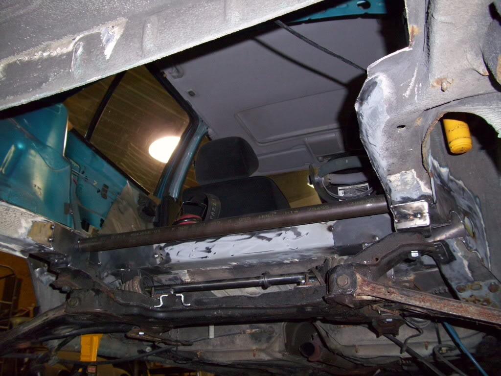
I did a bit more cutting
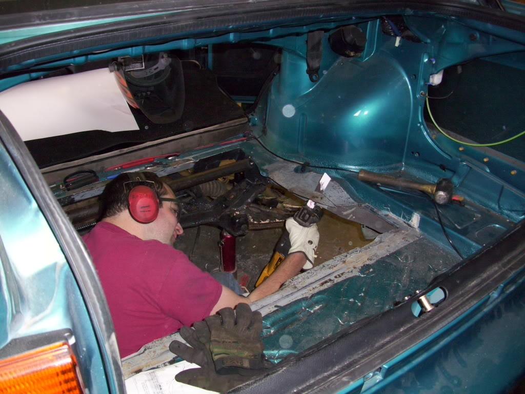
and some more welding
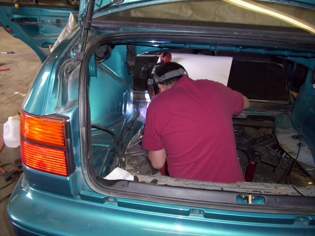
This crossmember will also serve as one of the mounting points for the fuel cell.
April 6, 2009
I welded in a second rear crossmember, behind the fuel tank. This would also serve as a mounting point for both my hydraulic pumps and my fuel cell, as well as stiffen up the chassis.
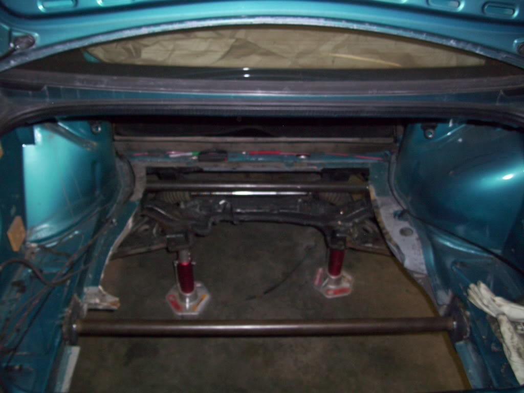
I welded 4" square plates from 1/8" steel onto the chassis rails before adding the tube, again to help spread the load and make a stiffer and stronger setup.
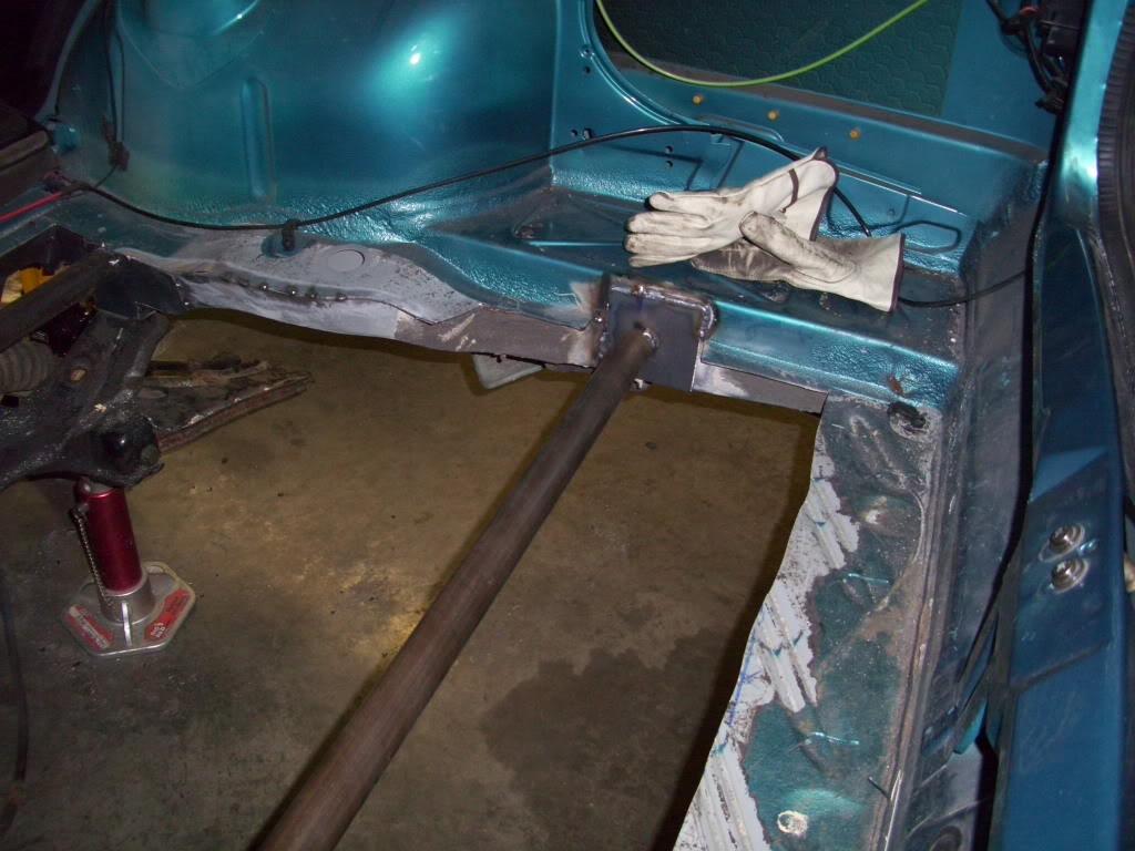
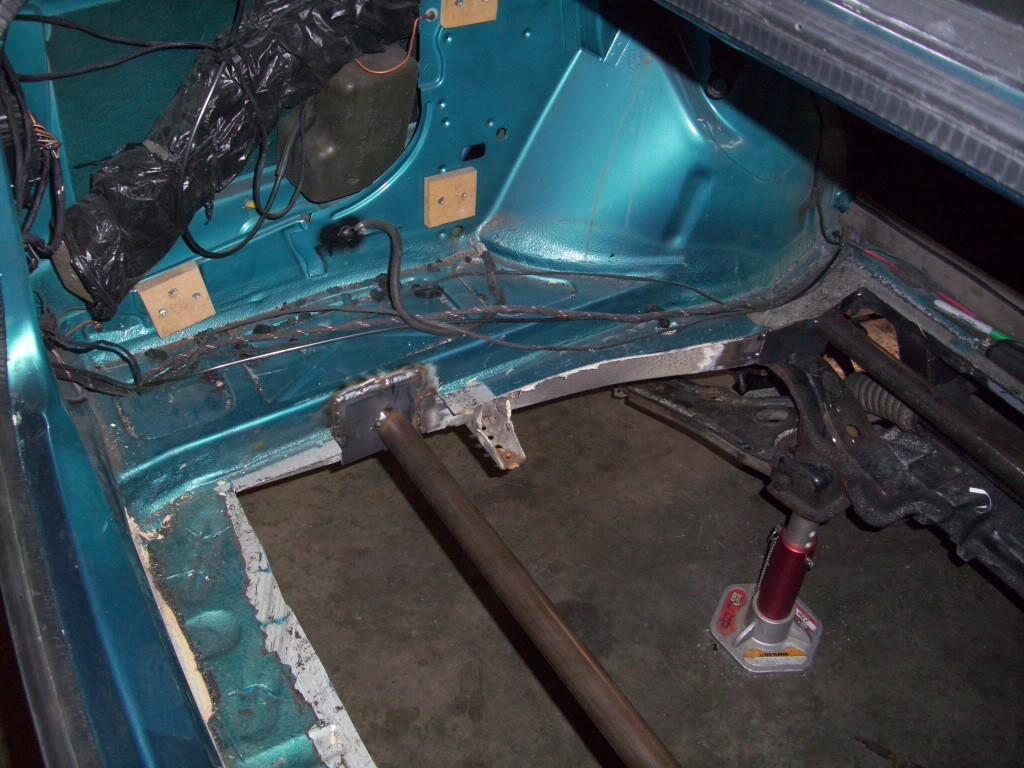
I also did some test bends with the tubing bender to see how it bent with the 1-1/4" .065w steel tubing, which I will use for the strut tower brace and fuel cell mountings.
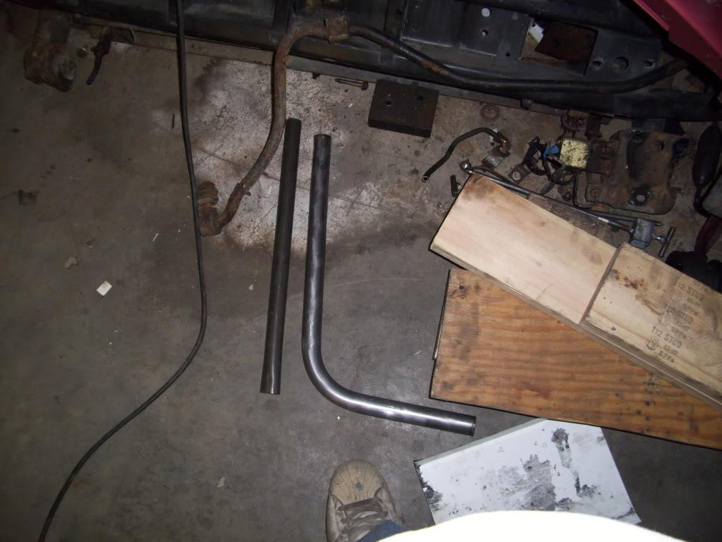
April 7, 2009
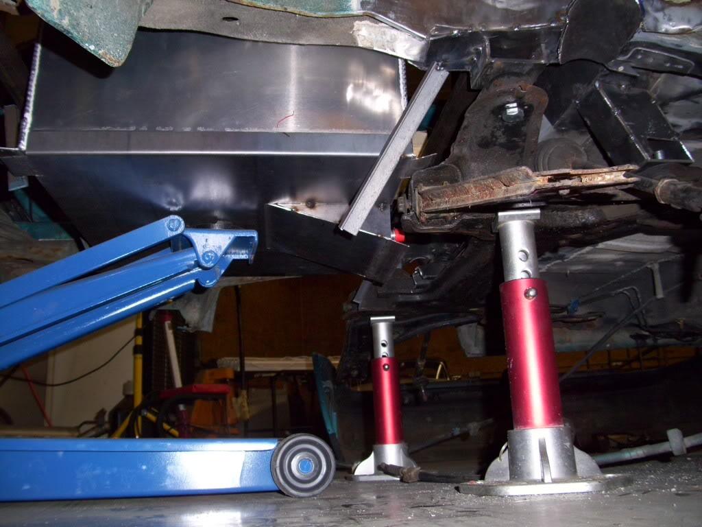
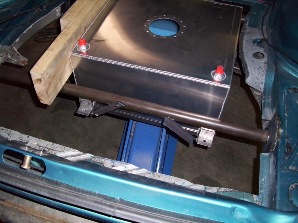
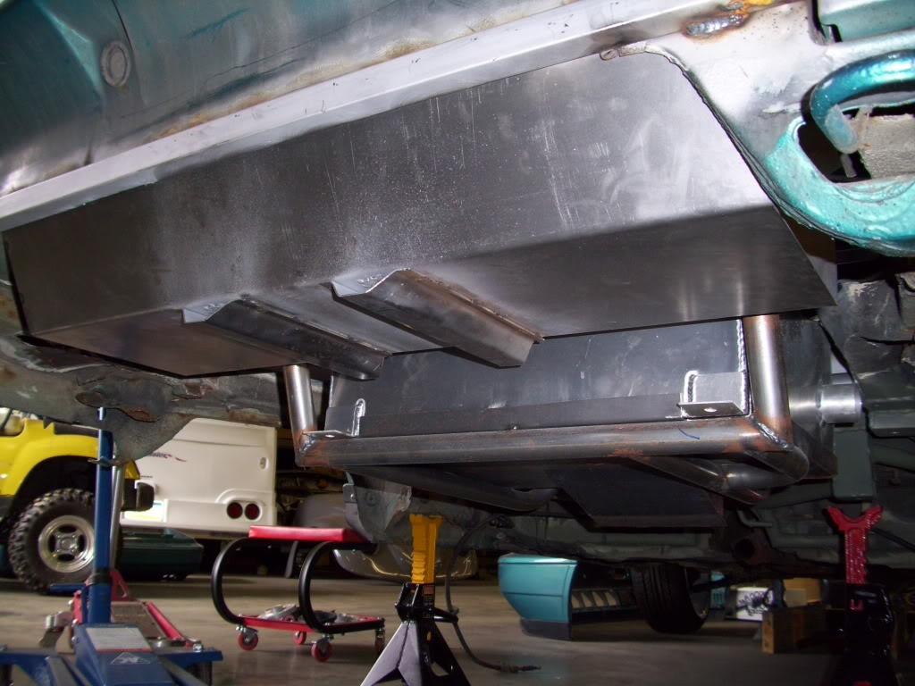
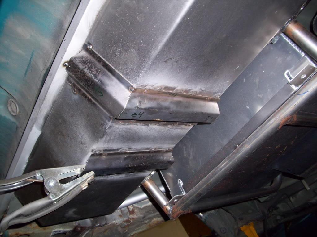
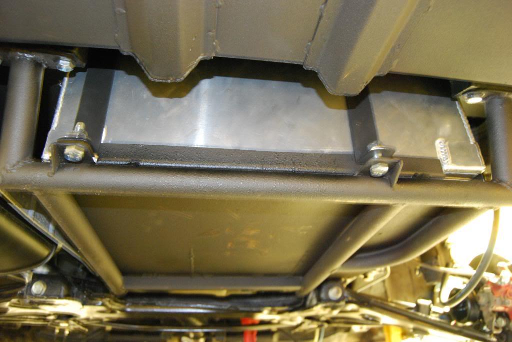
I began fabbing the fuel tank mounts. The plan is to have two long bent tubes which hang from the forward and rearward crossmembers and loop under the tank, which will provide both support and protection.
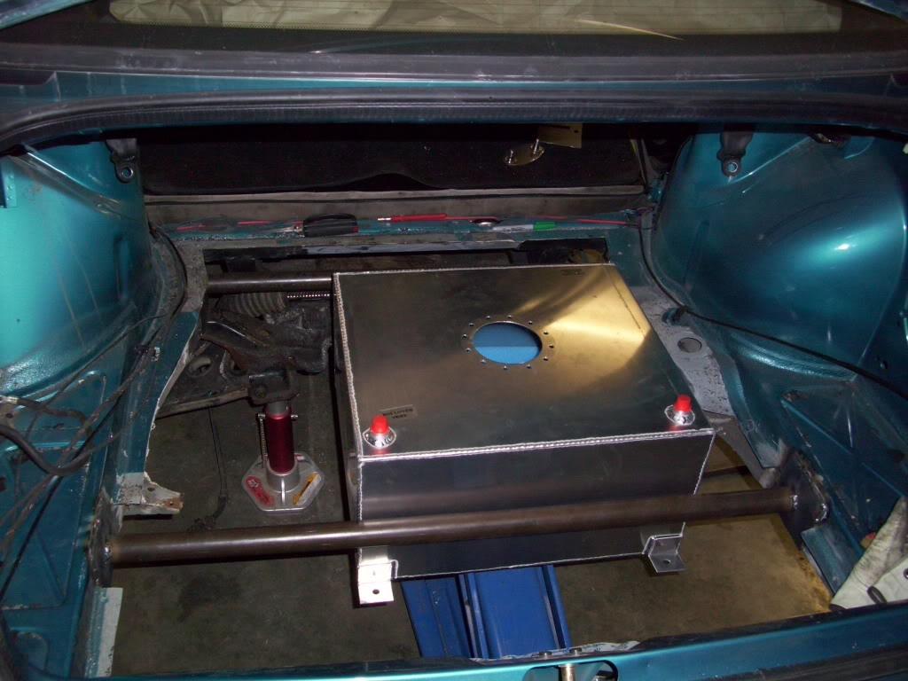
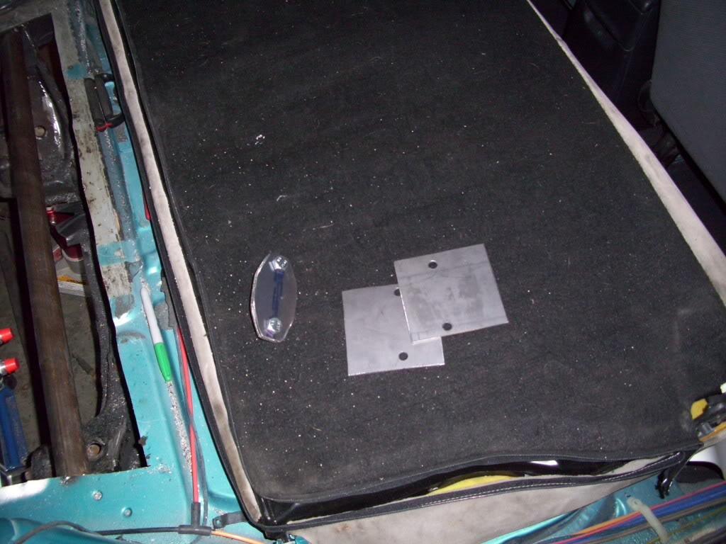
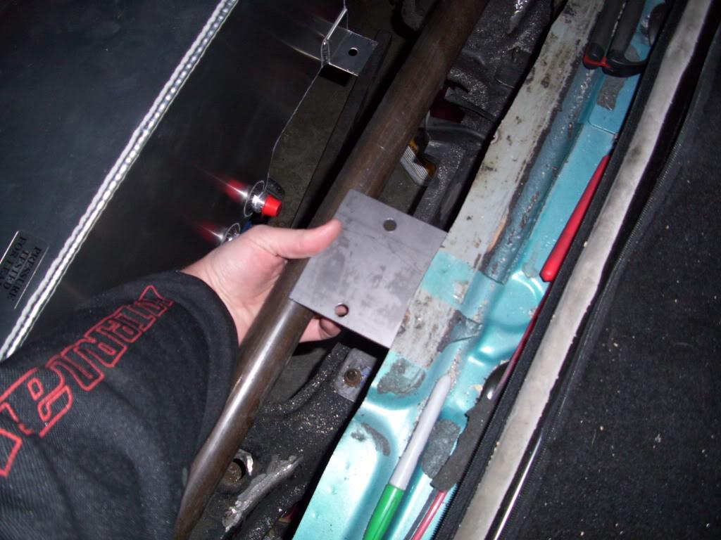
April 9, 2009
More tank mounting fab. These are the mounts which will mount to the crossmember and the plate that will go under the cell.
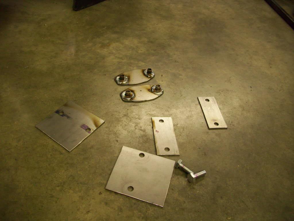
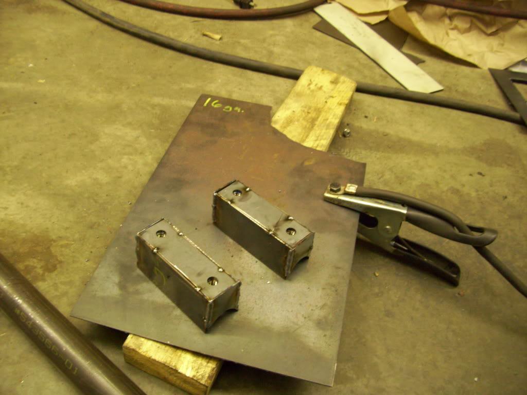
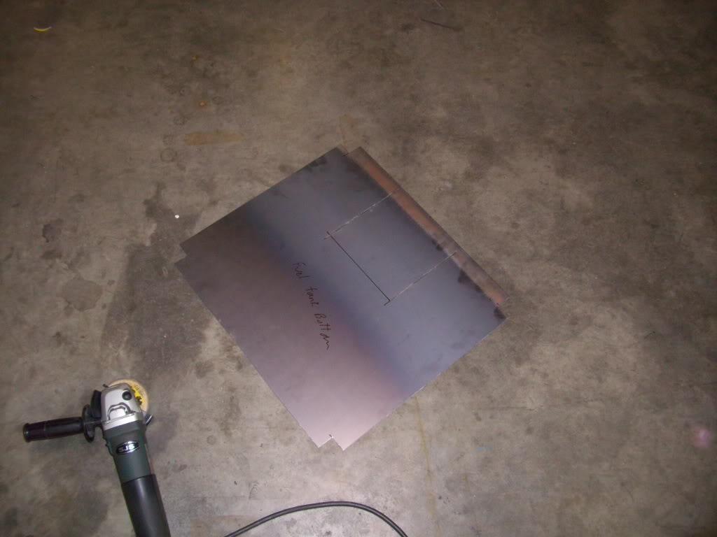
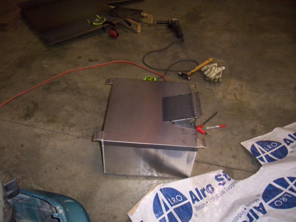
I tacked in some temporary mounting bars to hold the tank perfectly parallel to the trunk floor while I made the bars below.
April 11, 2009
Before permanently destroying the stock tank, I decided to run the motor one more time. This would allow me to track down any problems ASAP, so if I had a problem when the fuel cell was in I would know it was the fuel cell and not the other stuff.
I had the fuel cell laying on the floor with hoses everywhere and no exhaust... this was pretty sketchy
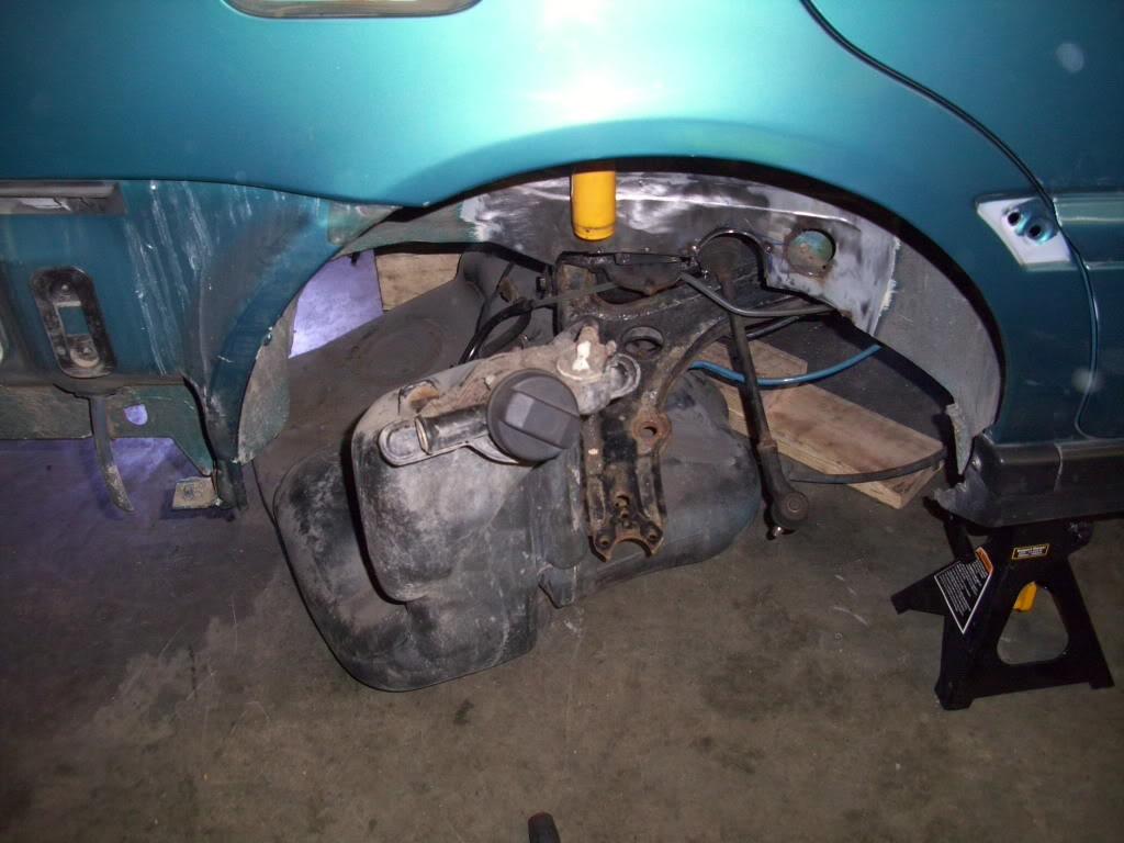
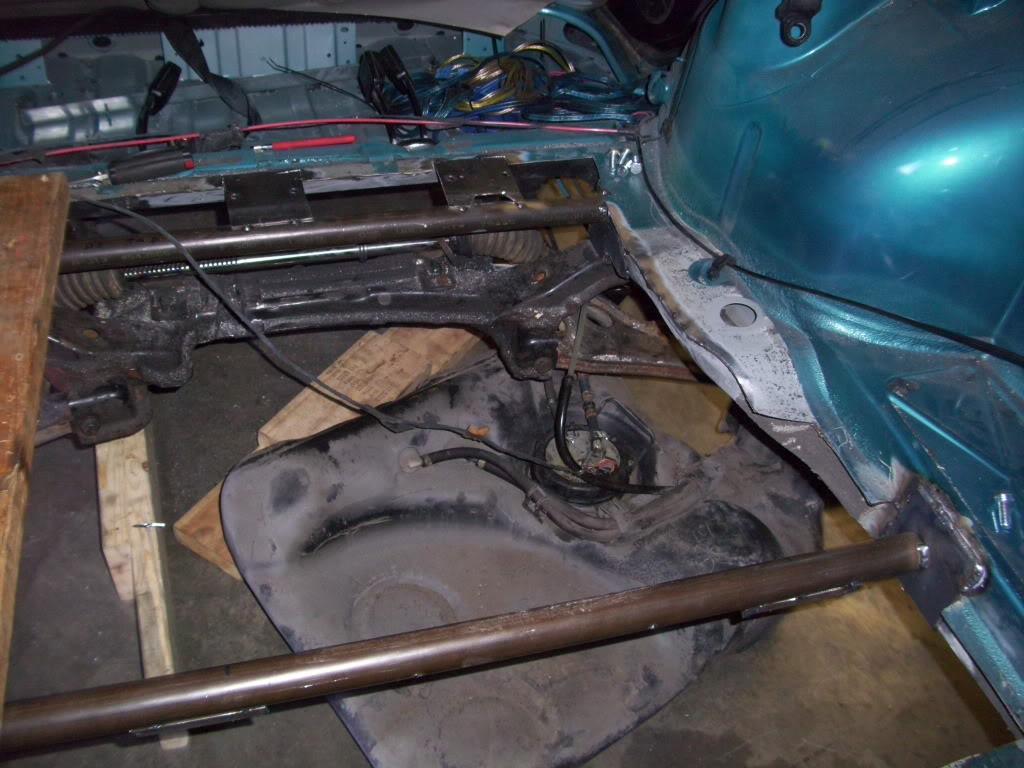
But the motor ran! For the last time until August!
Then I built the cradle for under the fuel cell.
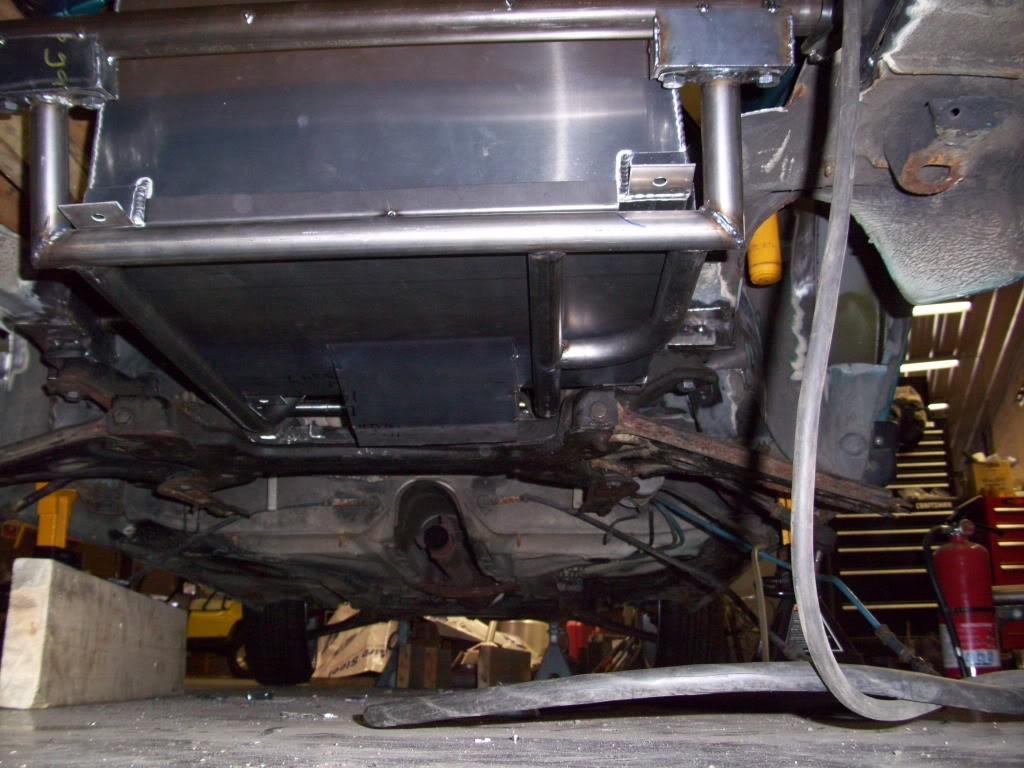
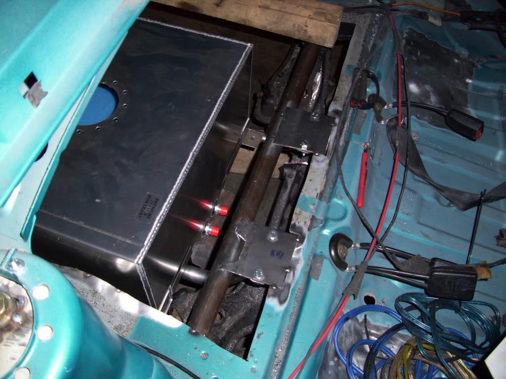
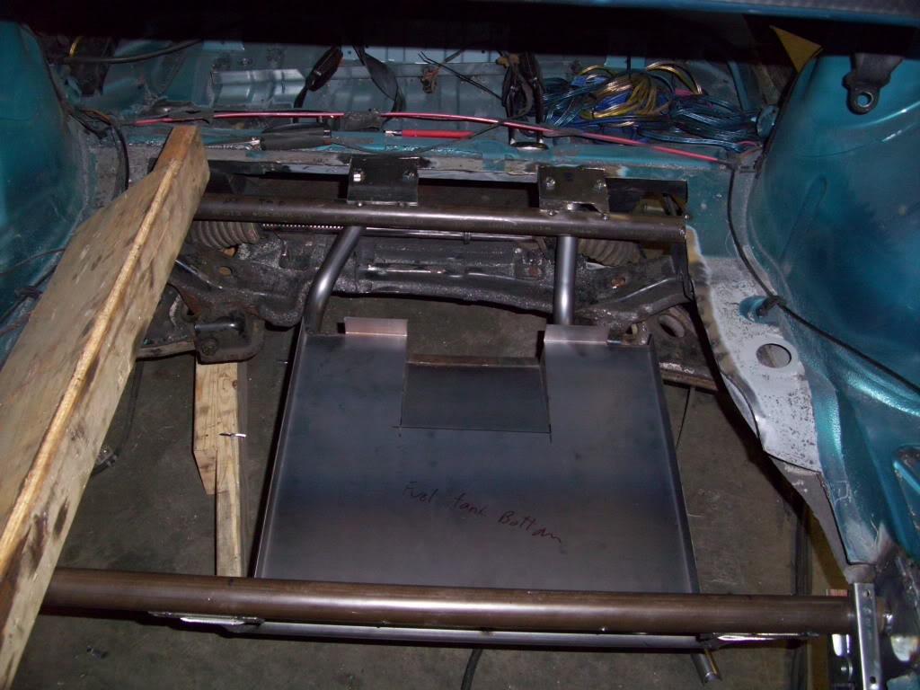
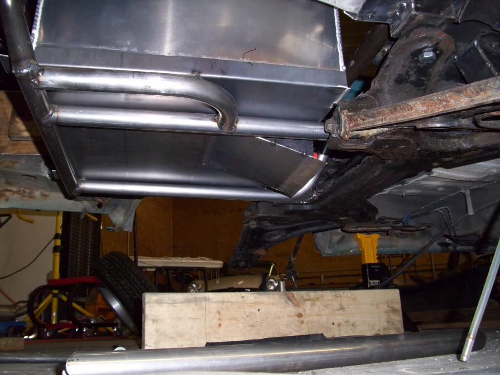
I added the little loopy thing in that last pic so I could remove the control arm bolt without dropping the tank.
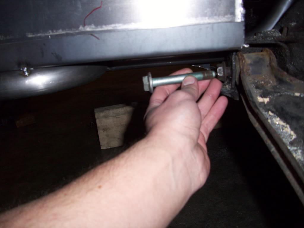
April 13, 2009
Apparently these Summit tanks aren't very flat on the bottom
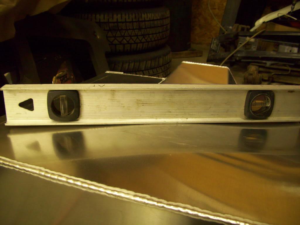
though I screwed up the cradle, but the tank was so warped it didn't sit flat. This was fixed later.
I mostly just did some (crappy) welding this day
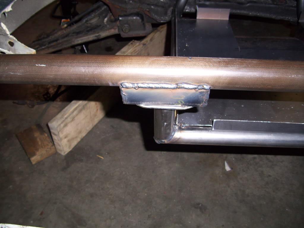
Seam welded some parts of the trunk floor which was removed

April 20, 2009
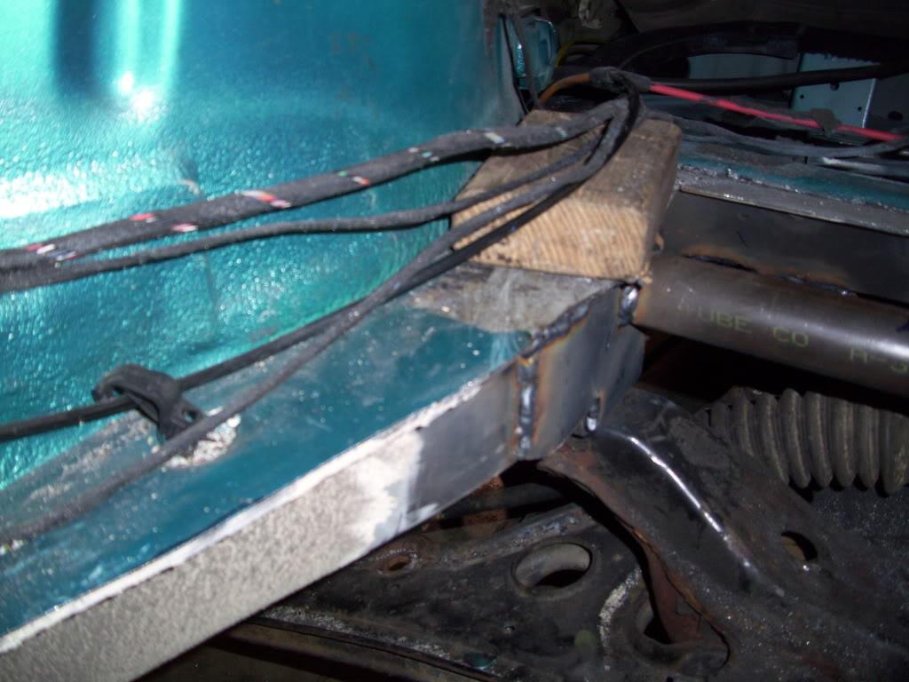
I ground down the welds around the tie rod notches so that I could add a large plate around the whole area to retain strength where the notch was, and to add strength where the subframe mounted.
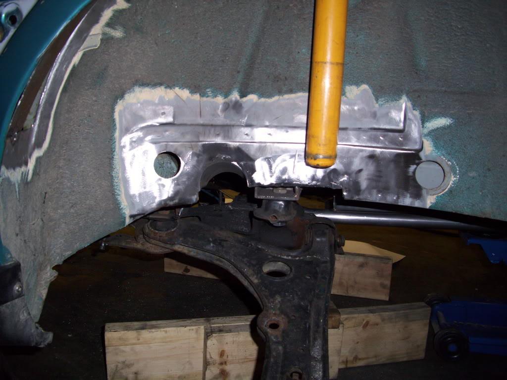
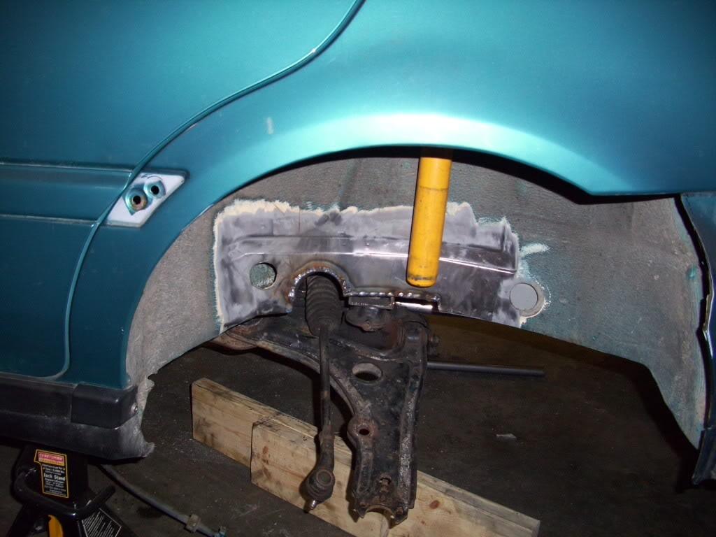
I also lowered my roommate's mk5 on black wheels and Koni coilovers.
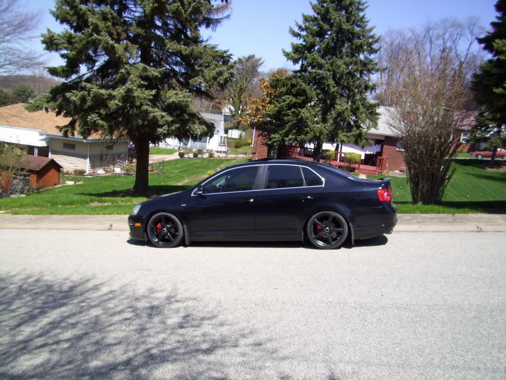
April 25, 2009
I cut and hammered out some plates from 1/8" steel to weld onto the frame rails.
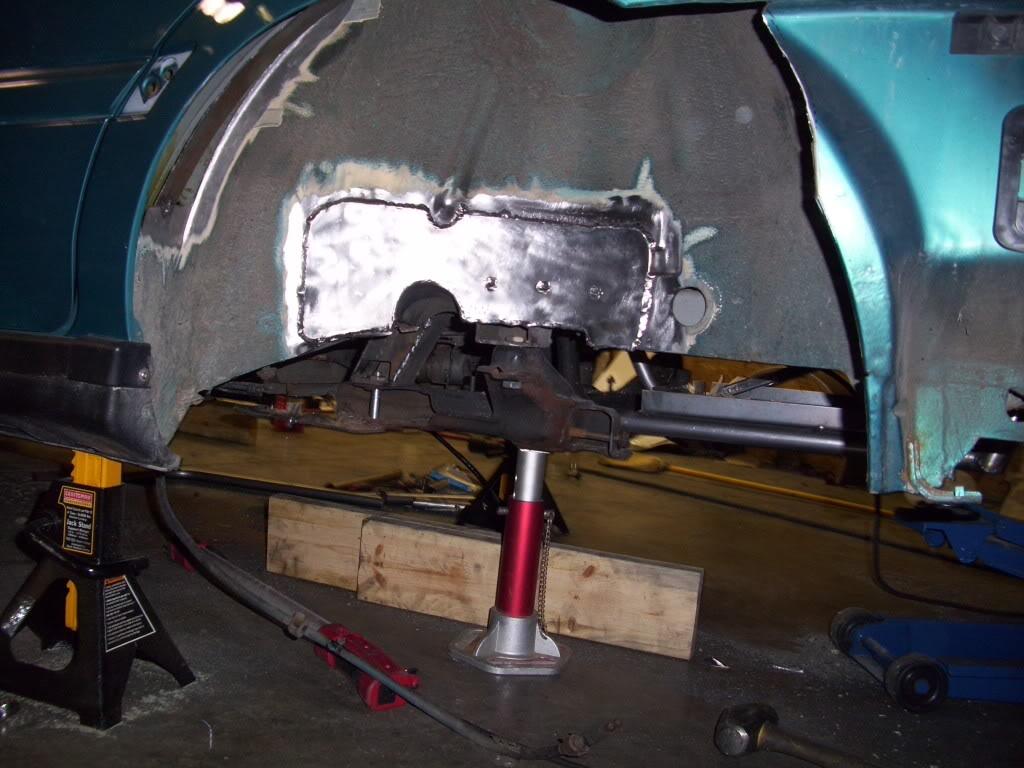
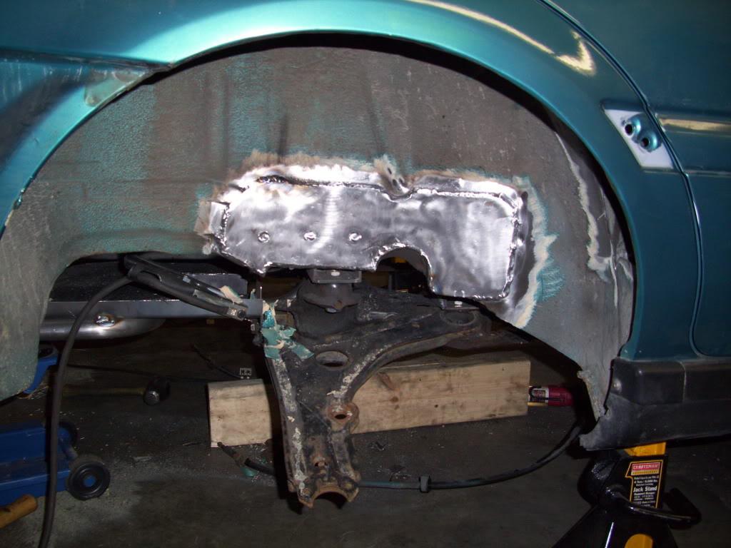
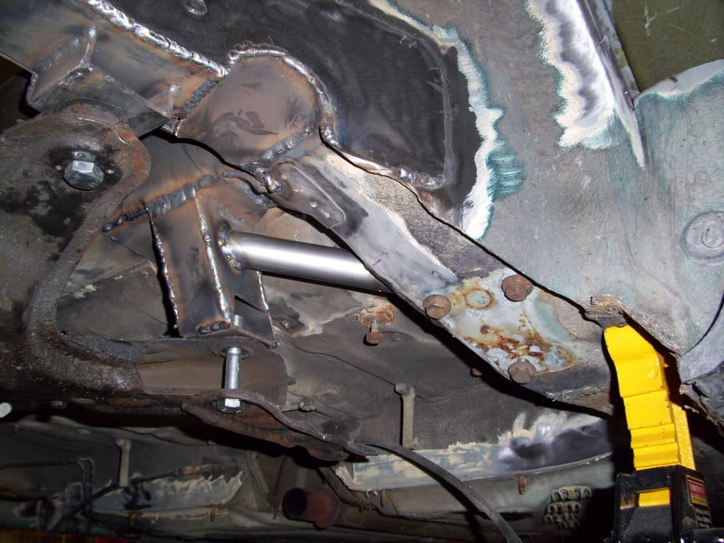
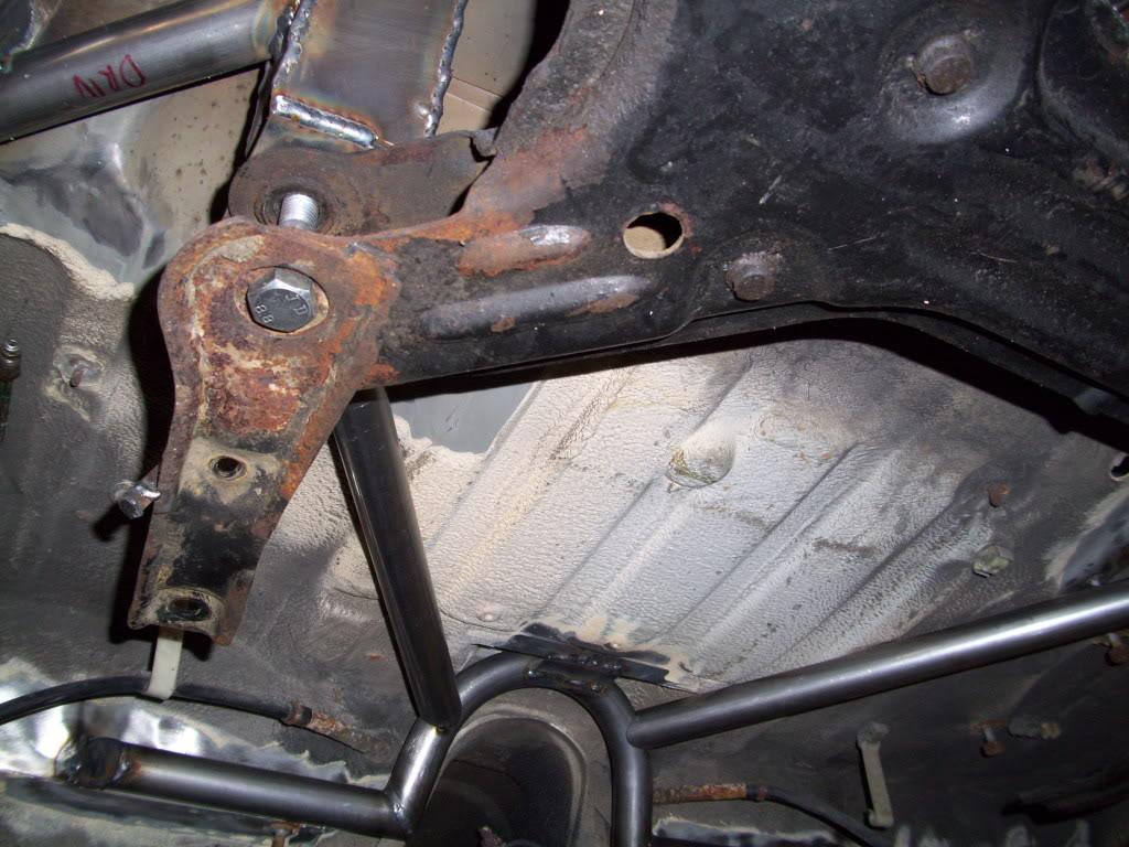
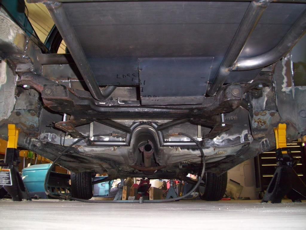
I added these short diagonals from the forward subframe mounts to the old rear beam mount area. This ties the subframe into one of the most structurally sound parts of the unibody.
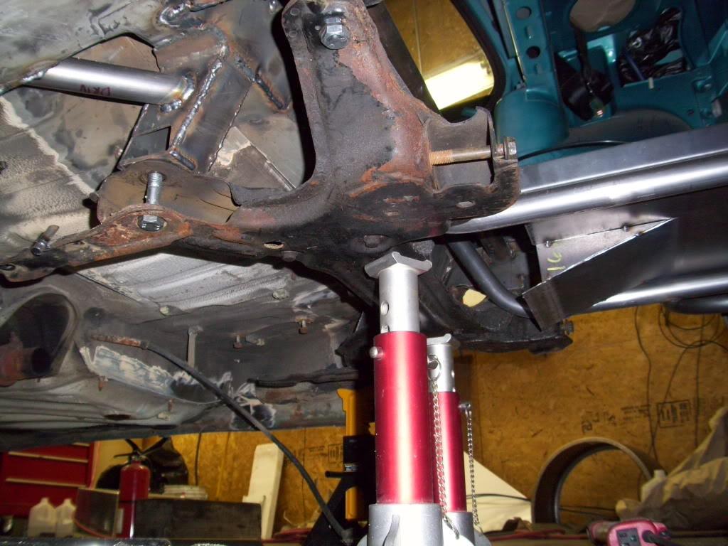
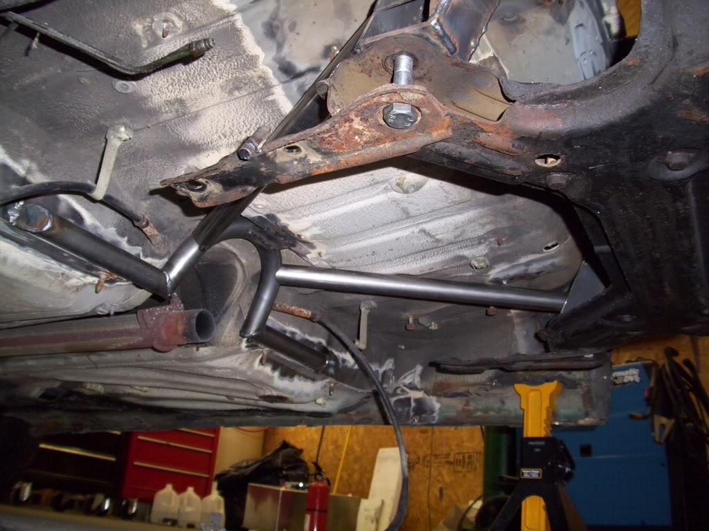
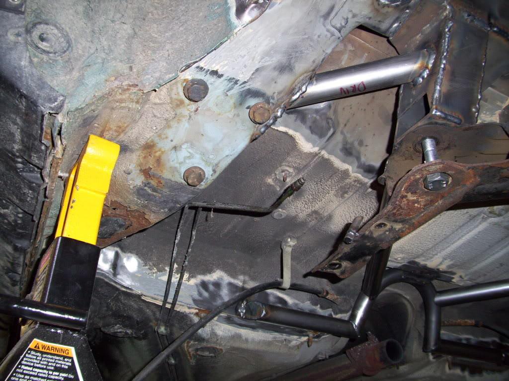
Then I made a hoop over the exhaust and added some forward diagonals, again to add some strength to the whole rear end. The exhaust tunnel and forward seat crossmember (under the front edge of theseat) are also very strong due to their shape and thickness, so I wanted to take advantage of this strength.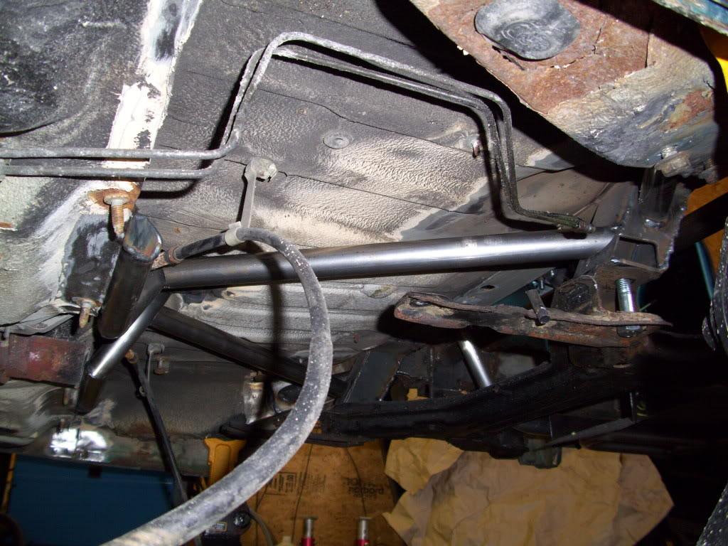
It was a nice day, so I took a picture of the 33 acre back field.
April 27, 2009
I started hammering out some panels for the rear tubs. These weren't quite as simple as the fronts, there was a lot of immoveable stuff in the way and I didn't have room to make a nice clean round tub. I had to do a lot of hammering and hand-forming to maximize the amount of room for the tires.
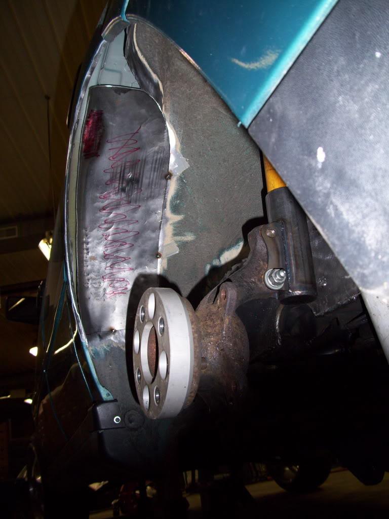
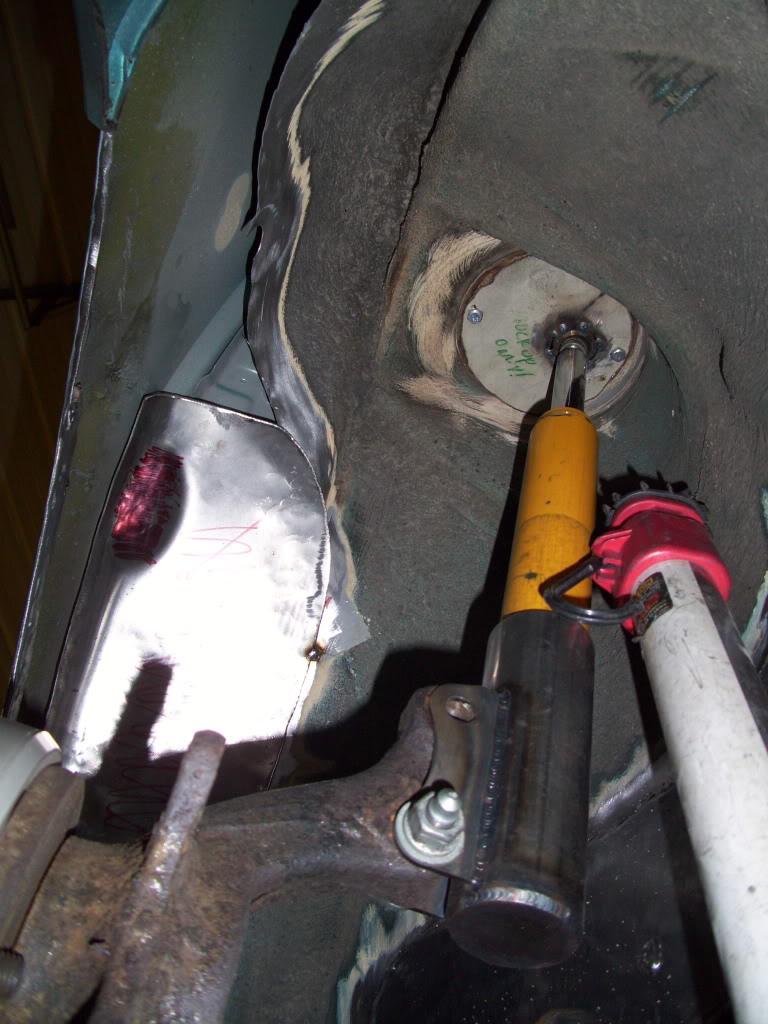
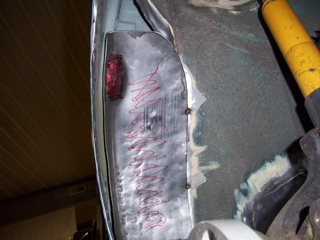
I marked it all up so I could roll the tire while jacking on the control arm and see where it was hitting. Once I saw where it was hitting, i could hammer more until it hit somewhere else. Repeat until it hits directly under the door jamb, which cannot move.
May 3, 2009
I continued work on the rear wheel tubs, including some rust repair work around the fuel filler area.
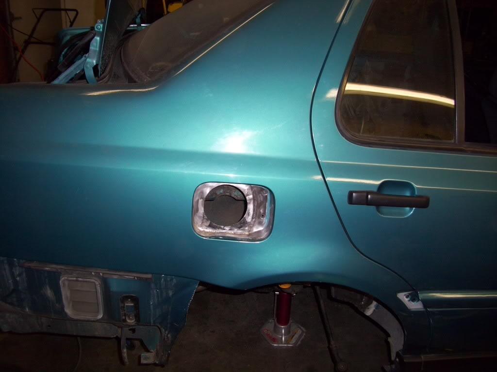
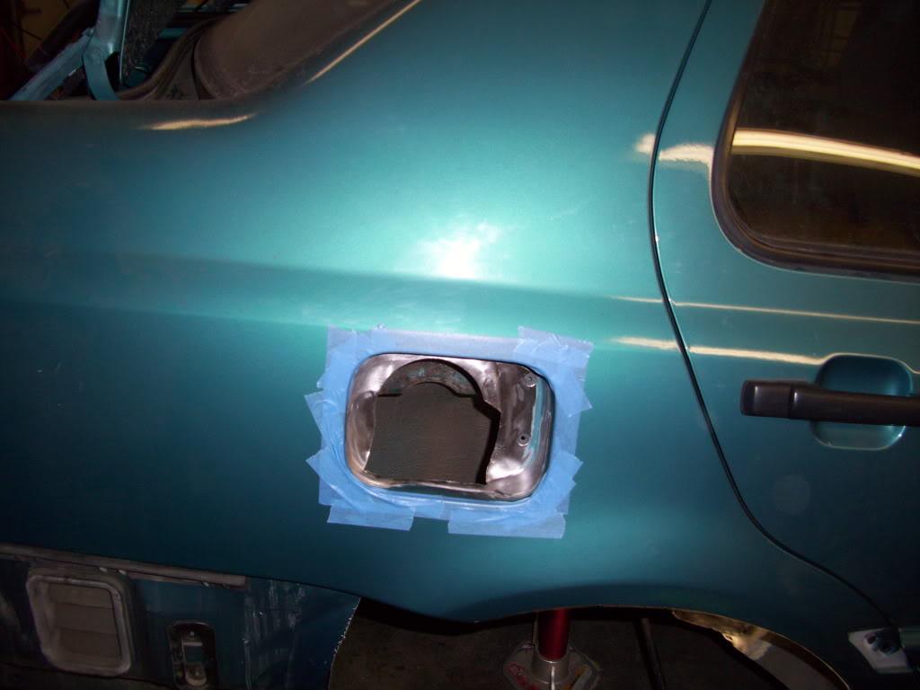
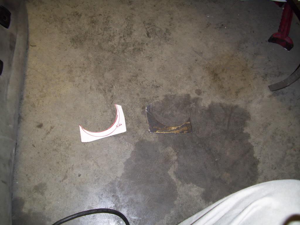
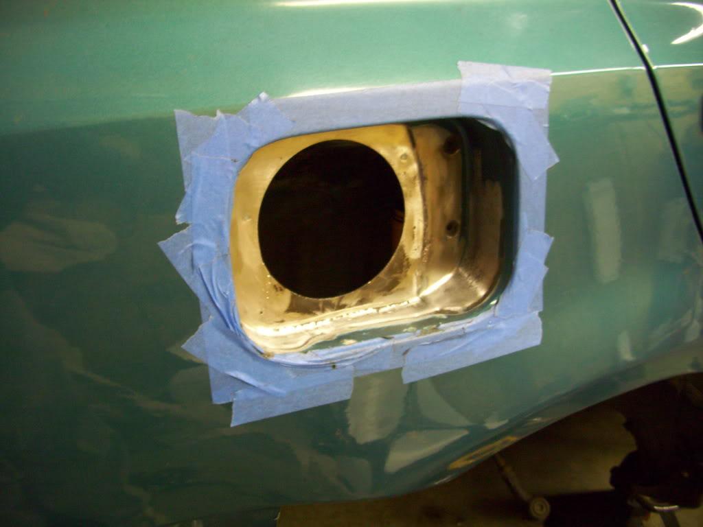
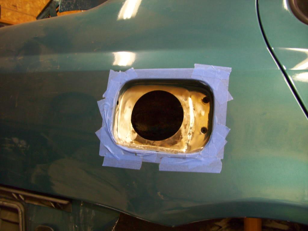
This is all from the passenger side tub, around the fuel filler neck area
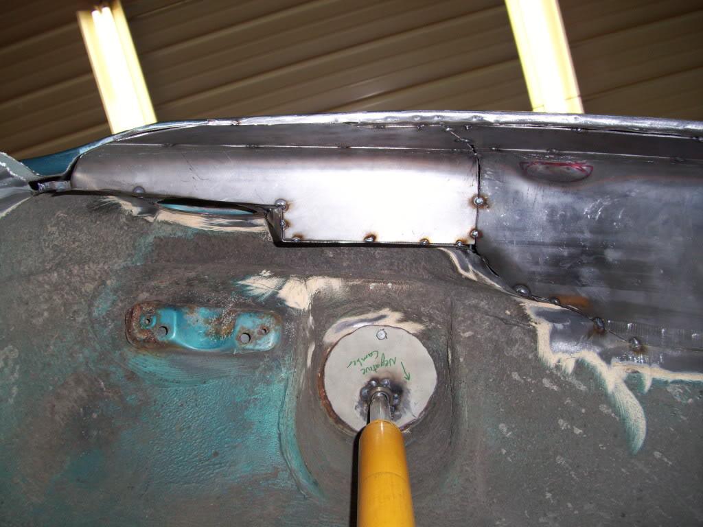
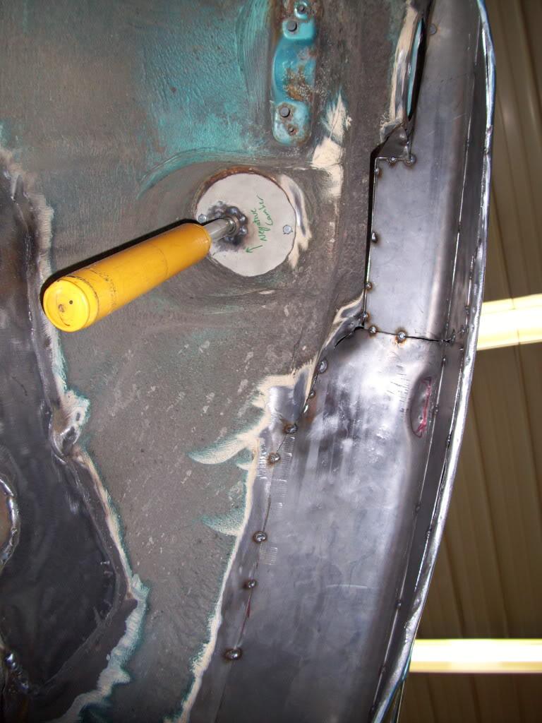
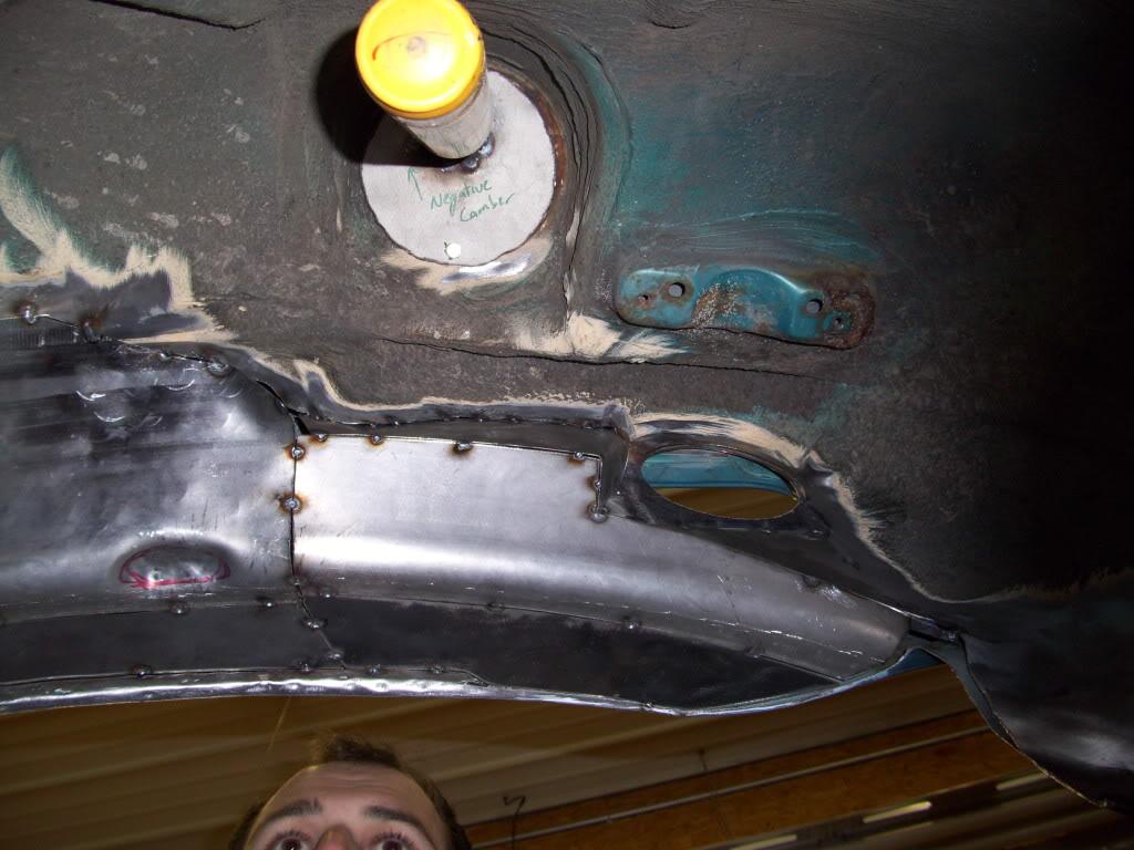
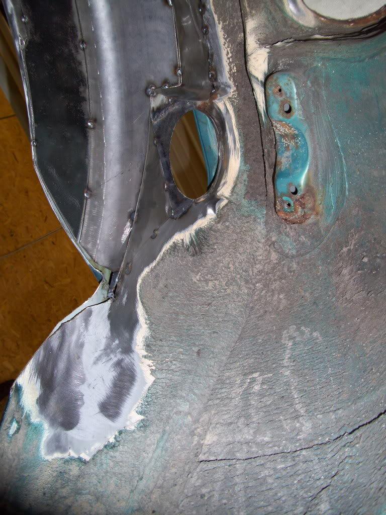
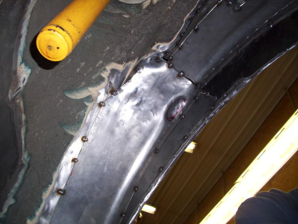
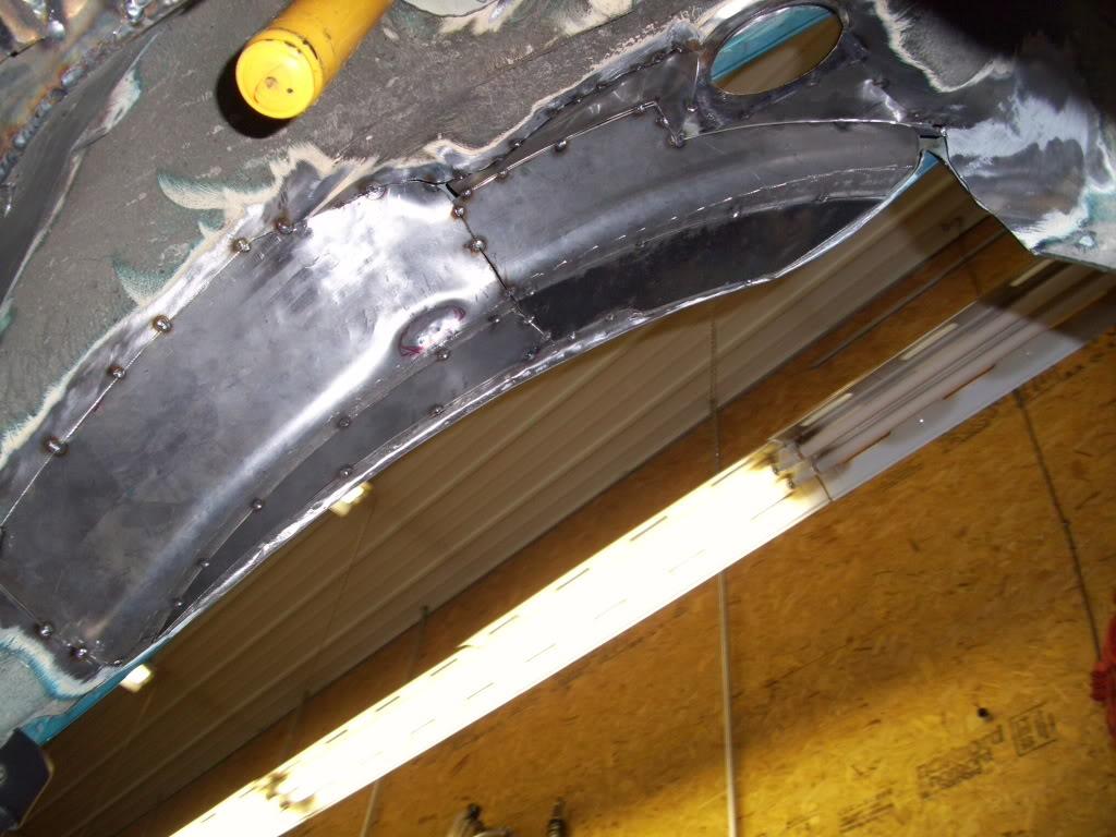
Yet another test fit. The rear was 1/2" lower with the tubs all tacked in place, so that's good enough for me! It leaves some room to run larger wheels, plus I don't have to cut through the door
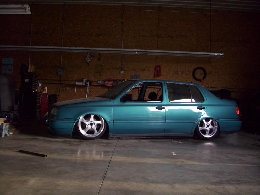
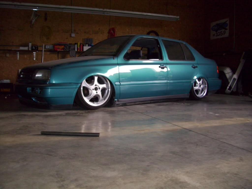
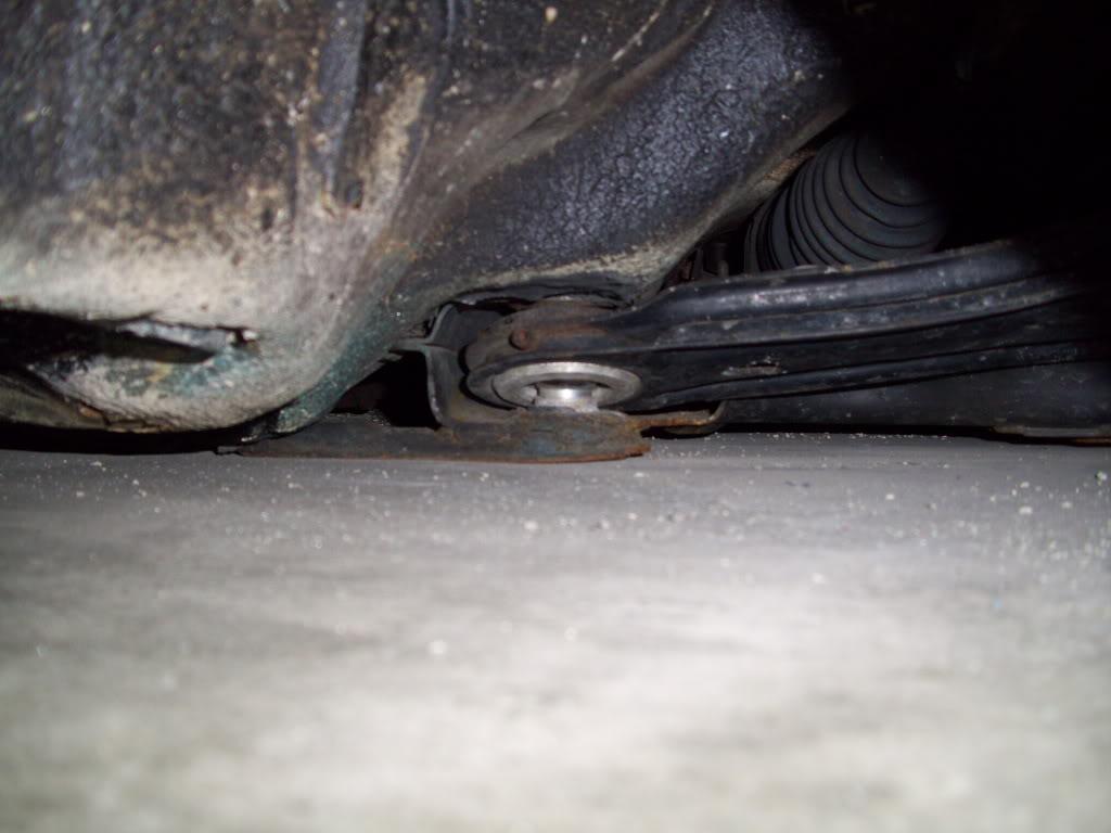
The tire is sooooo close!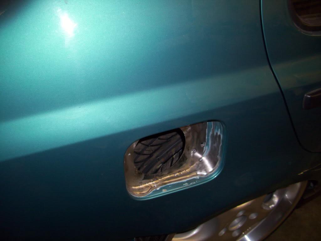
I got some more hydraulic parts back from the shop, and changed the design a bit since the last pics several months prior.
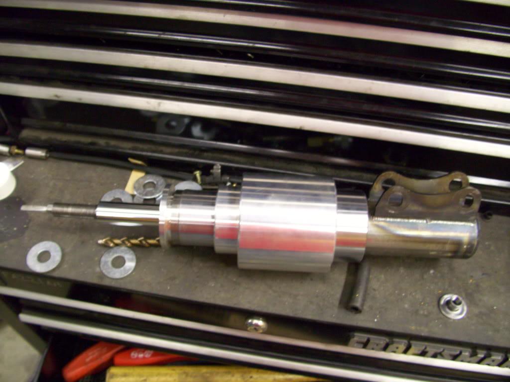
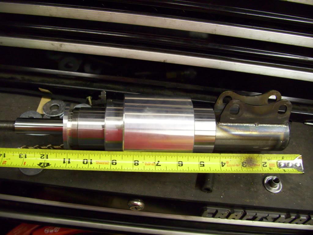
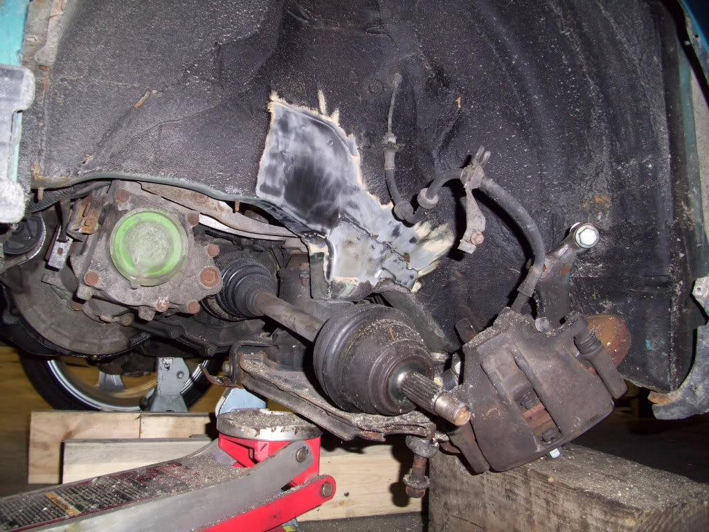
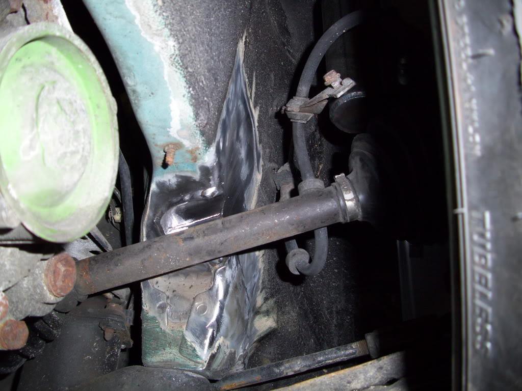
I also determined the front drivers side needed a c-notch. It still laid frame, but the axle was buried against the chassis. So I made this wee little baby notch.
When stripping the paing, I found these weird vertical tooling marks on the chassis. Difficult to photograph, but you can faintly see them. Has anyone seen this before?
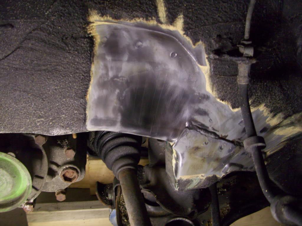
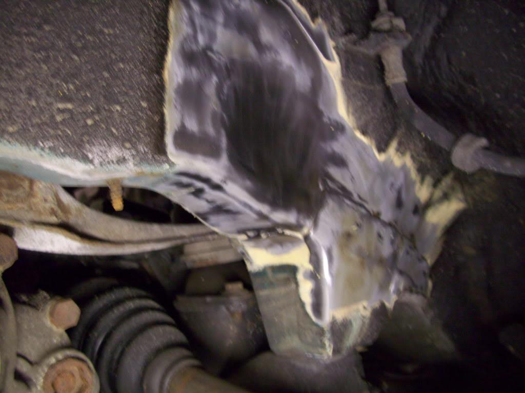
Again, I angled the notch to match the axle angle and make it all as small as possible. As notched frames get more and more common, we can't forget how sketchy this really is without proper reinforcement. Minimizing the structural impact on the chassis should be a consideration.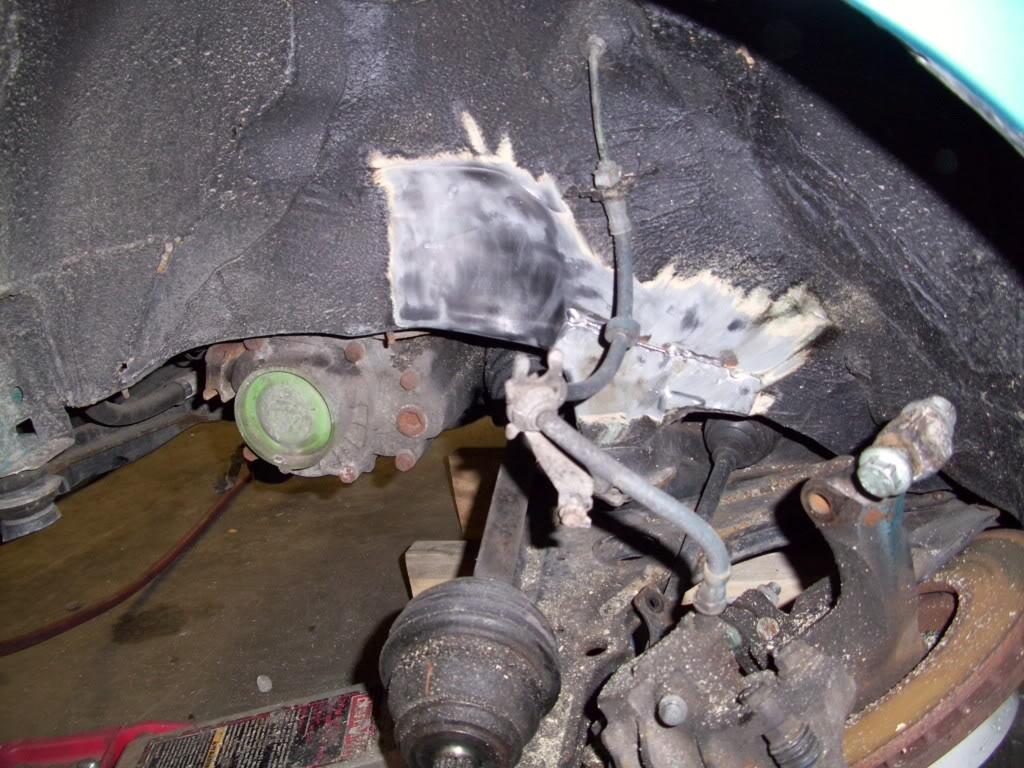
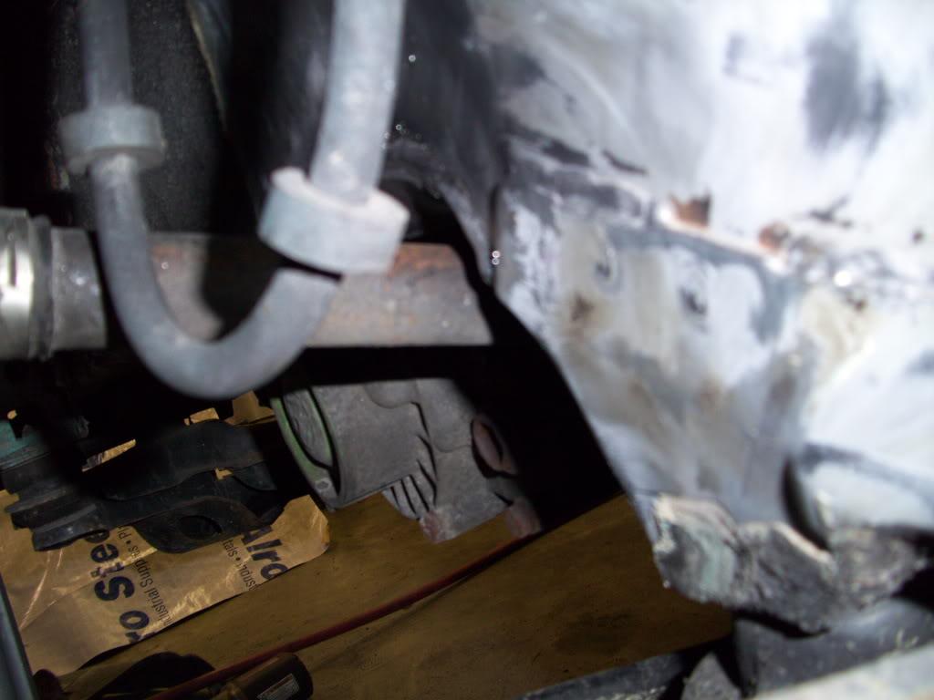
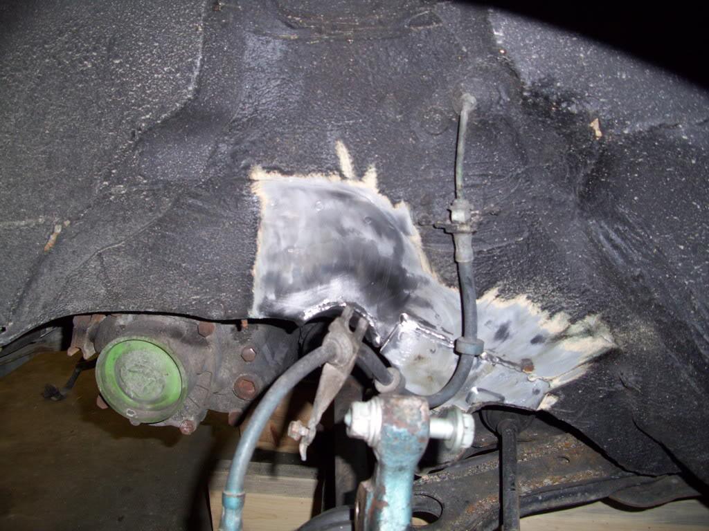
May 9, 2009
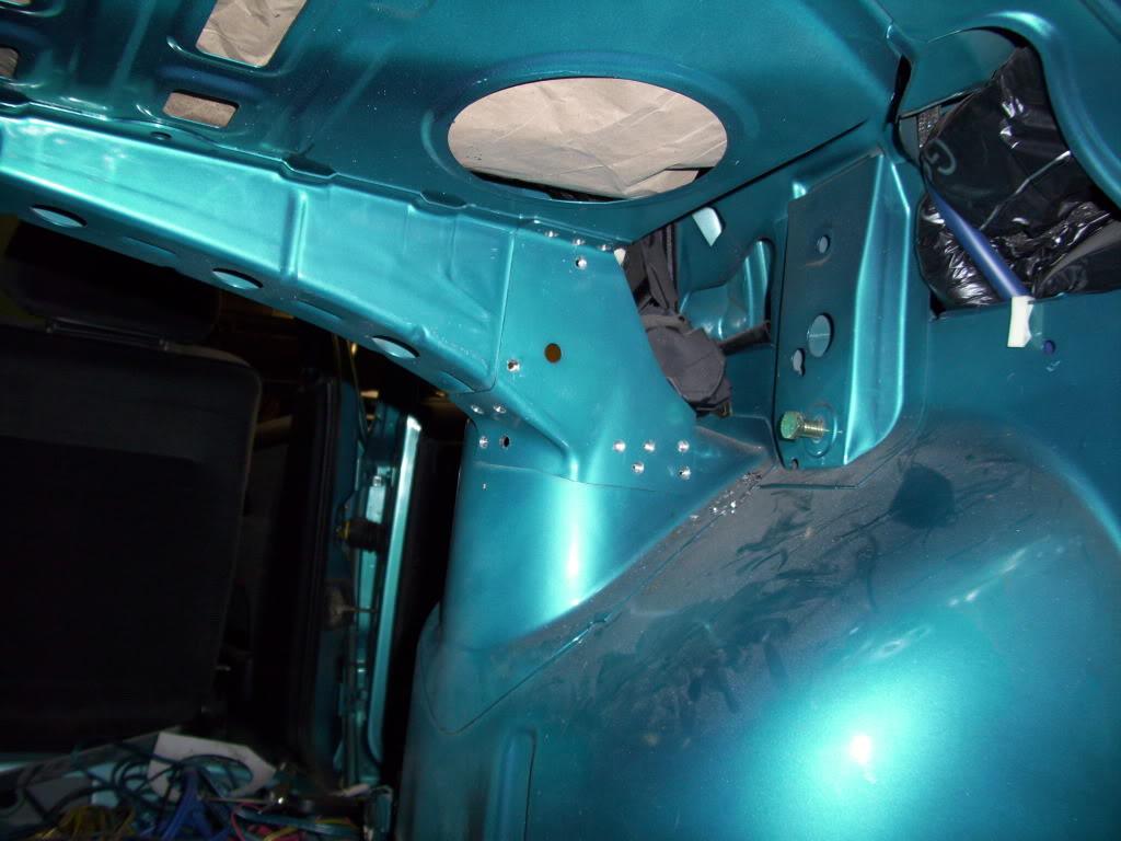
I got some Eurosport camber plates for the rear, and had to cut out the rear shelf brackets in order to weld all around the rear tower.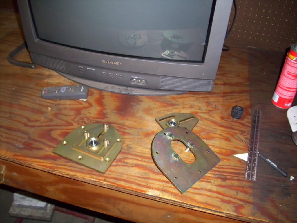
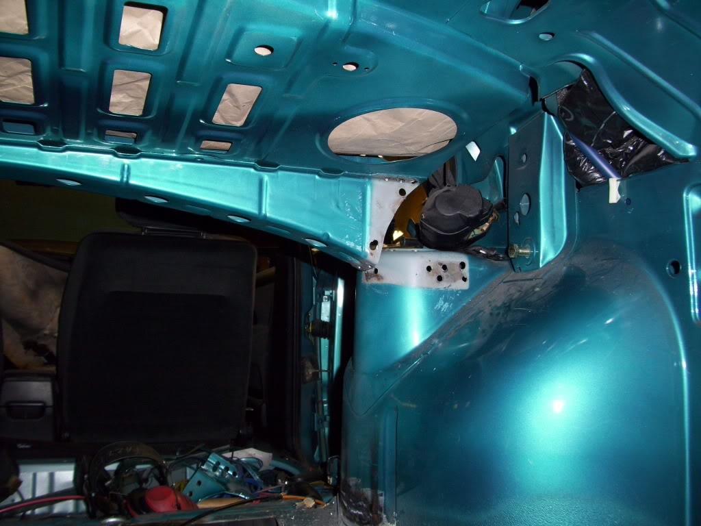
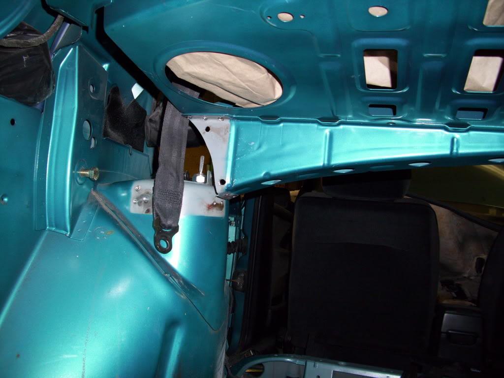
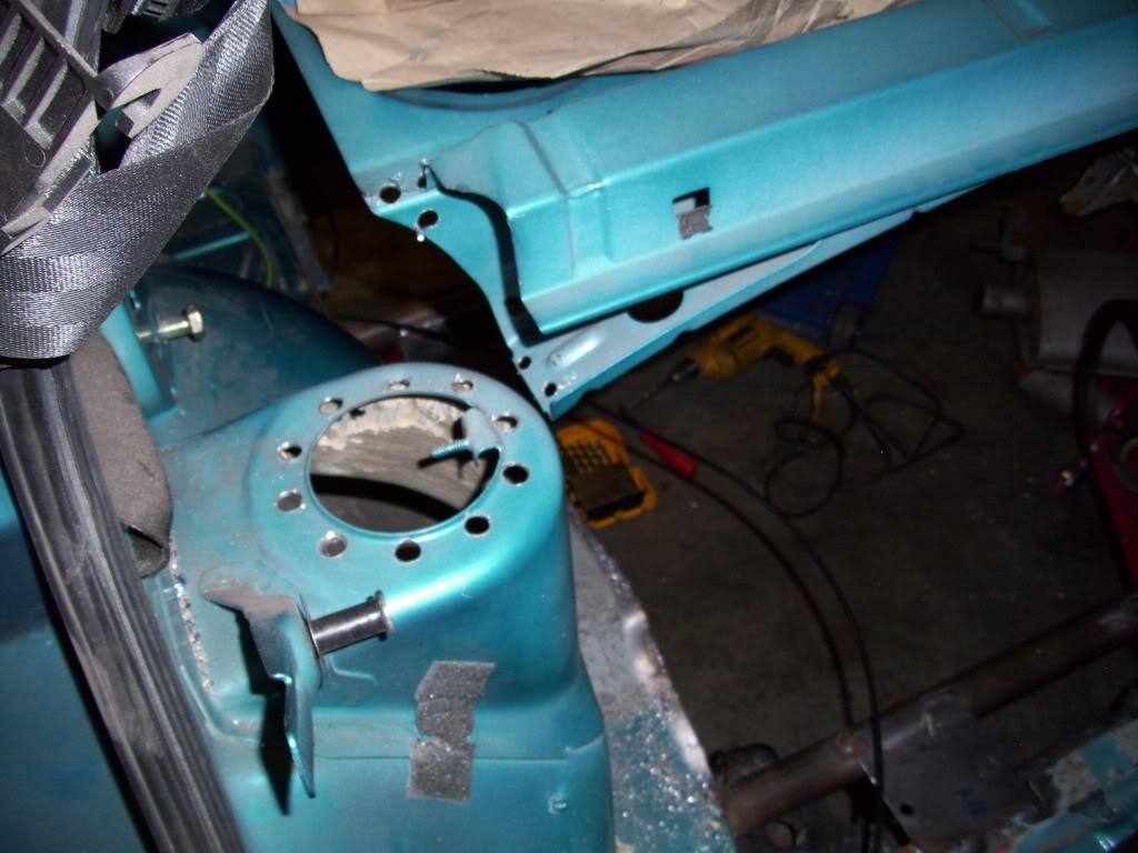
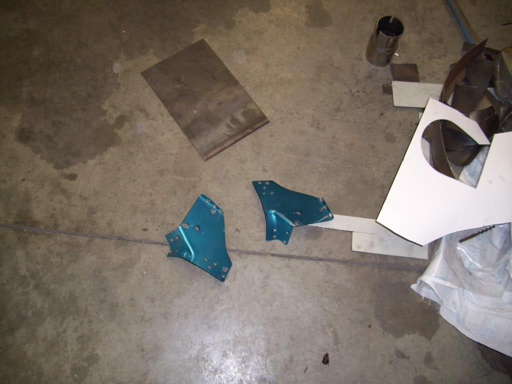
May 11, 2009
I normally don't have much bad to say, but these Eurosport camber plates aren't the greatest. I really don't recommend them at all. They work alright for the rear, since it doesn't steer, but I couldn't imagine having these in the front of a street car. These will probably be replaced with Ground Controls in the future, which are absolutely badass in all ways. These squeek and bang and are just a bad design. I had to completely modify them into what I wanted, so they turned out alright then.
I ground off the one stud and welded it flush. These are both in various states of completion
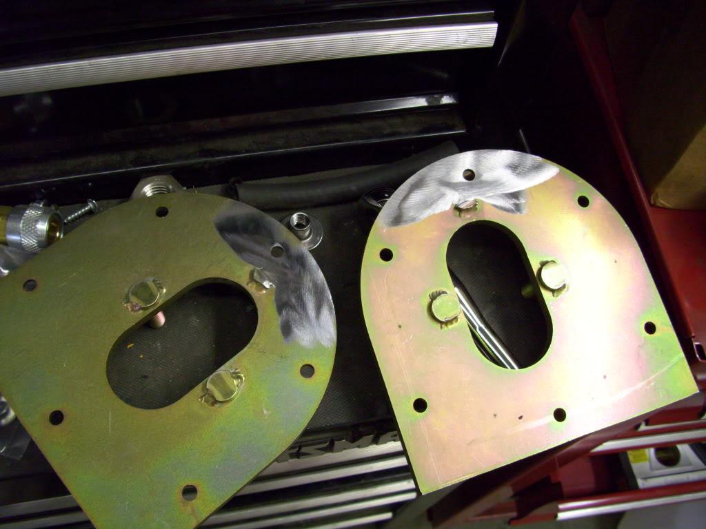
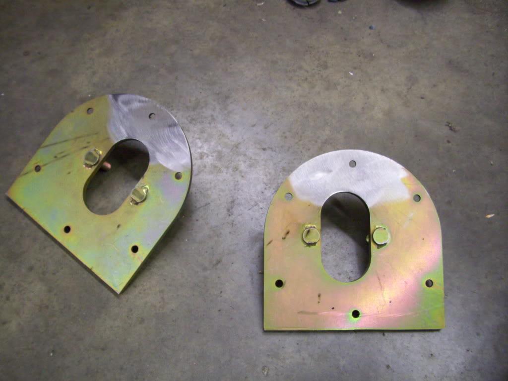
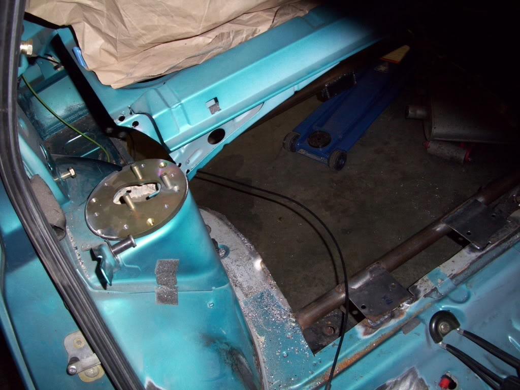
I made this steel ring, which will weld to the chassis. Then the camber plate will bolt onto this. Using a standard bolt pattern, I have the ability to rotate the camber plate in 60º increments to make it a caster plate, camber plate, or some combination of both. This allows me to fine tune the position of the rear wheel, both front-to-rear and side-to-side by changing the caster angle or SAI angle.
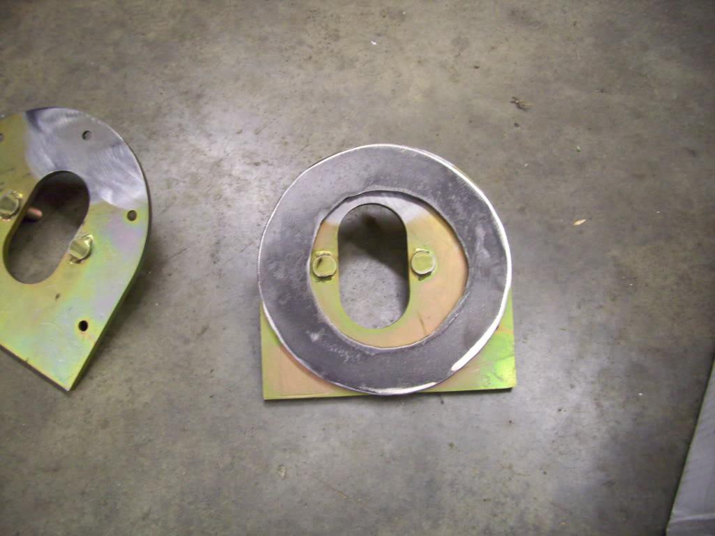
I cut the plate round for clearance.
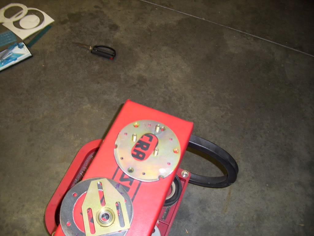
Camber plate:
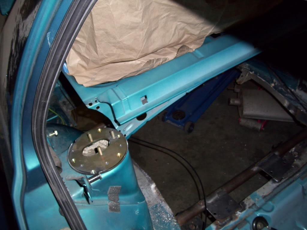
Or combination camber/caster plate just by turning it by one bolt.
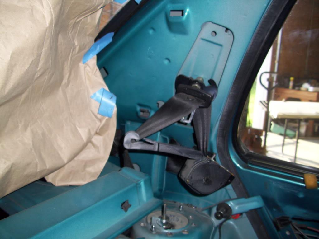
I took a bunch of pictures of hte rear seatbelts for future reference, in case I forgot how to put them back together.
May 17, 2009
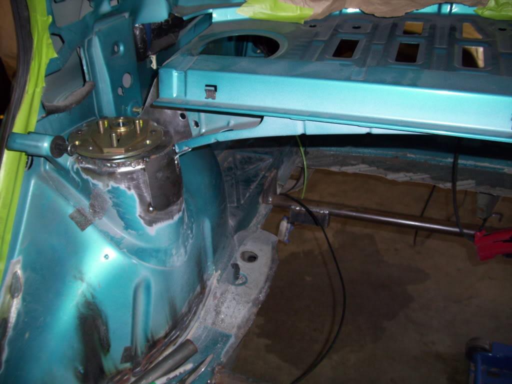
I welded the rear camber plate mounts into the towers.
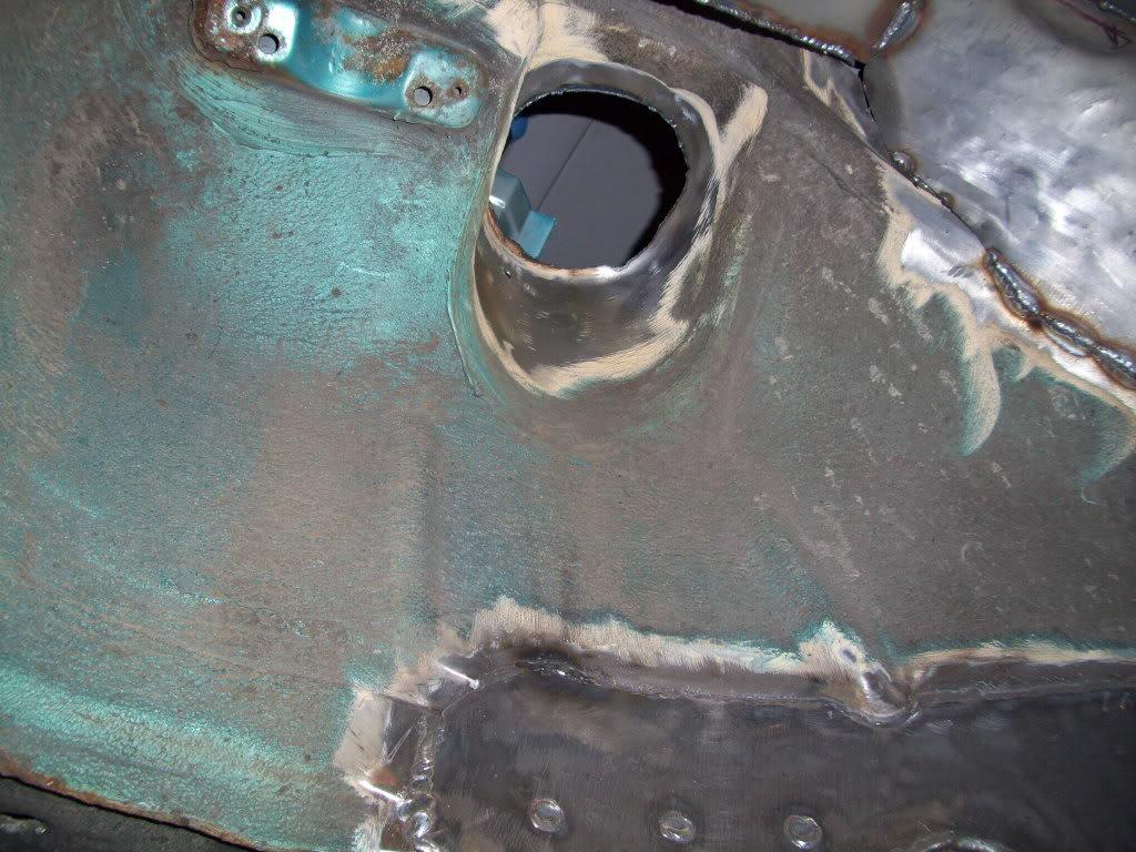
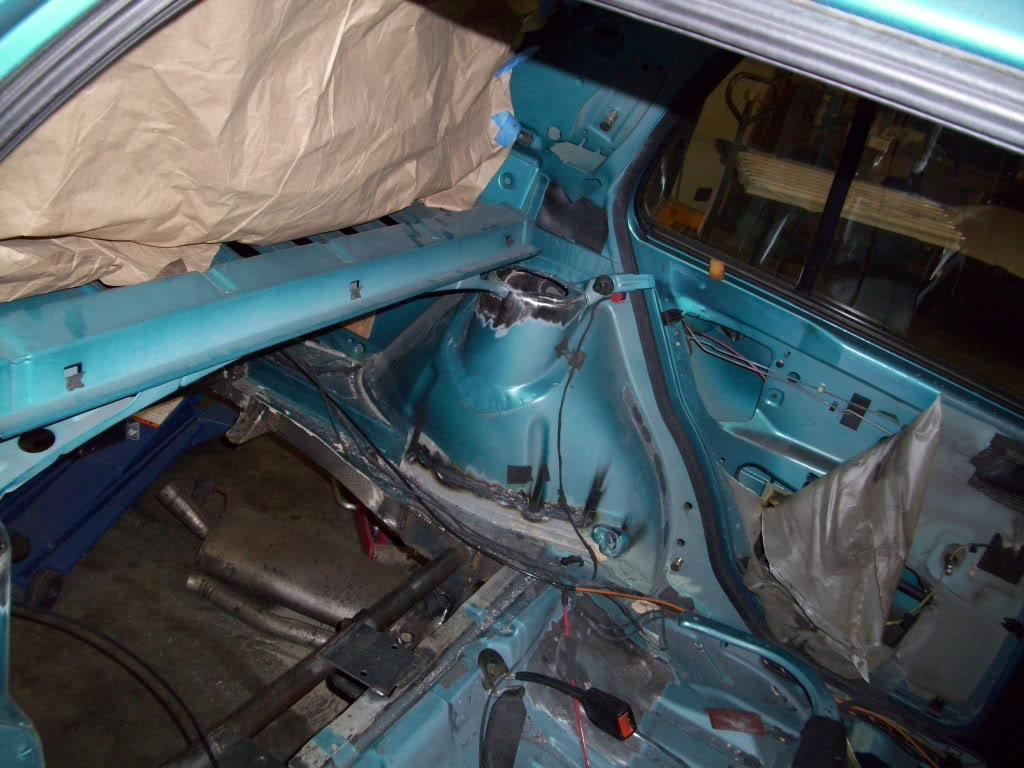
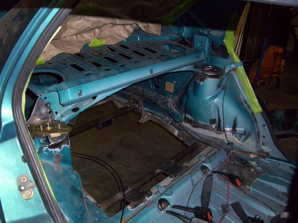
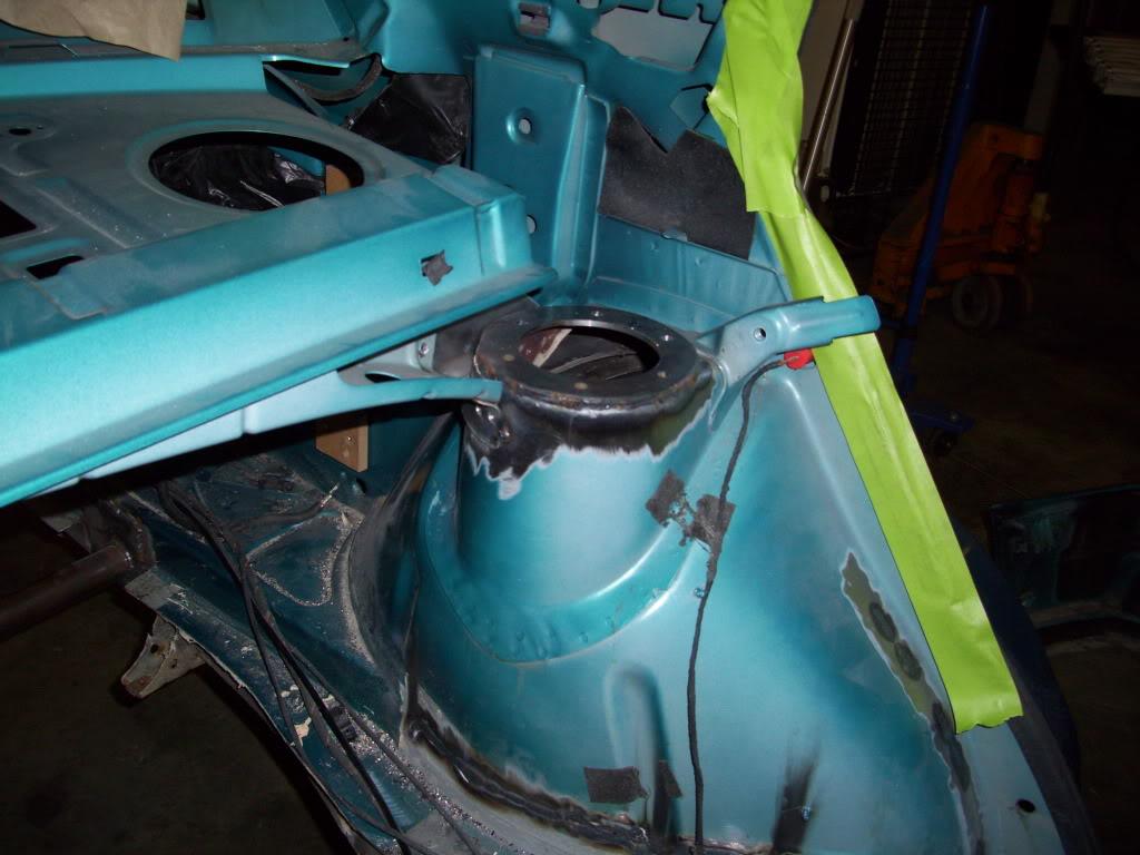
Put the rear shelf brackets back in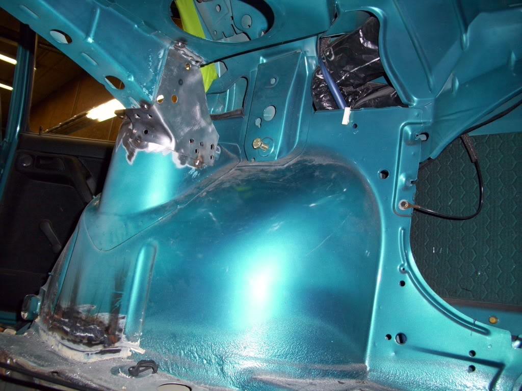
Then I welded in a strut tower brace.
First I cut a flat template, which will weld to the tower. This is 1/8" steel plate, again plating the area where tubing intersects the unibody steel to spread out the load.
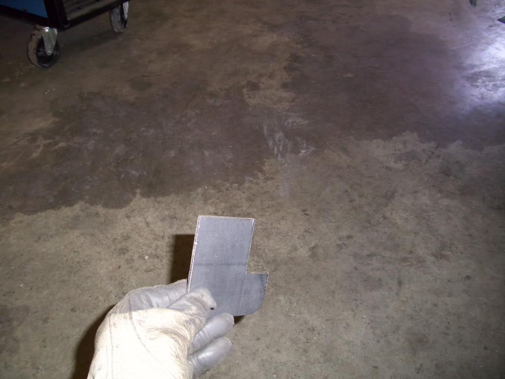
Then I roughed it into shape with a sledge.
Stop! Hammertime.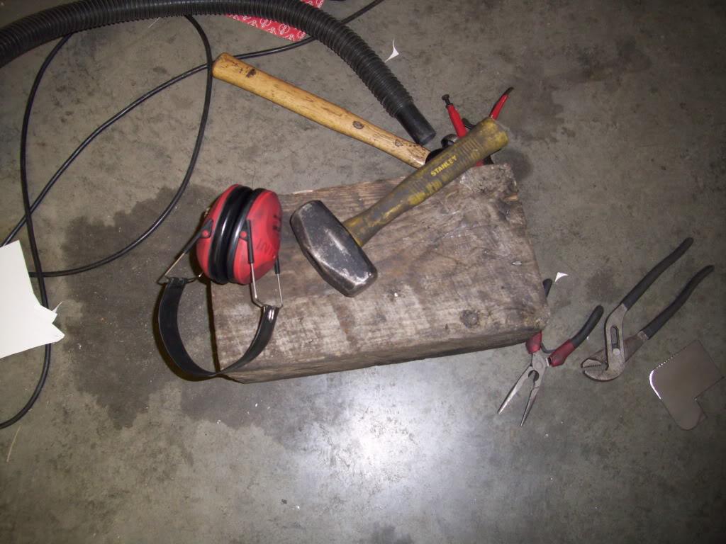
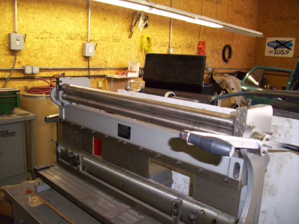
Then I cleaned up the hammer marks and got a uniform curve in the slip roll. The rolls aren't strong enough to curve the 1/8" steel in one shot without the hammering.
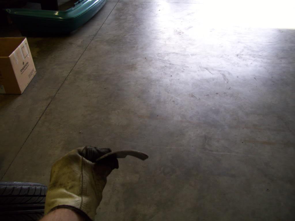
Perfect fit!
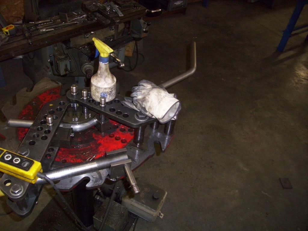
I fired up the tubing bender, and made a tower brace to roughly match the curve of the stock rear shelf. I couldn't match it exactly, but I did two bends.
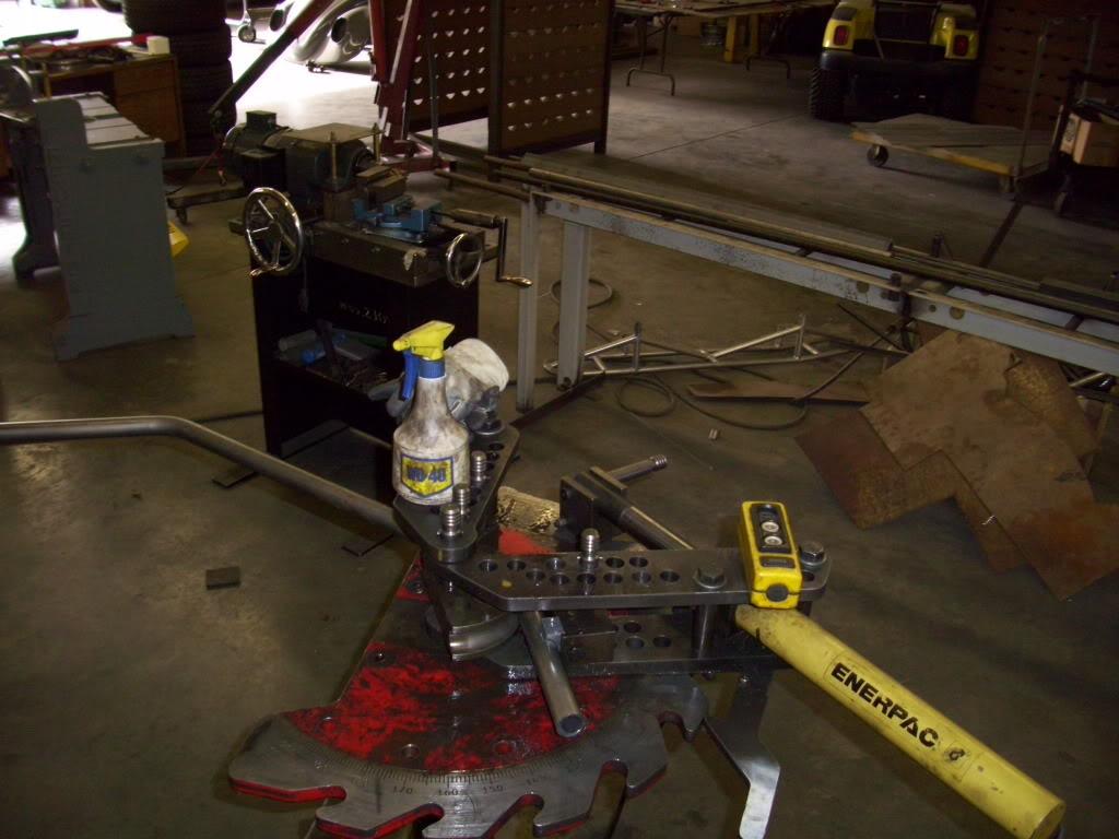
I didn't like the first one, the angle was too low on the strut tower
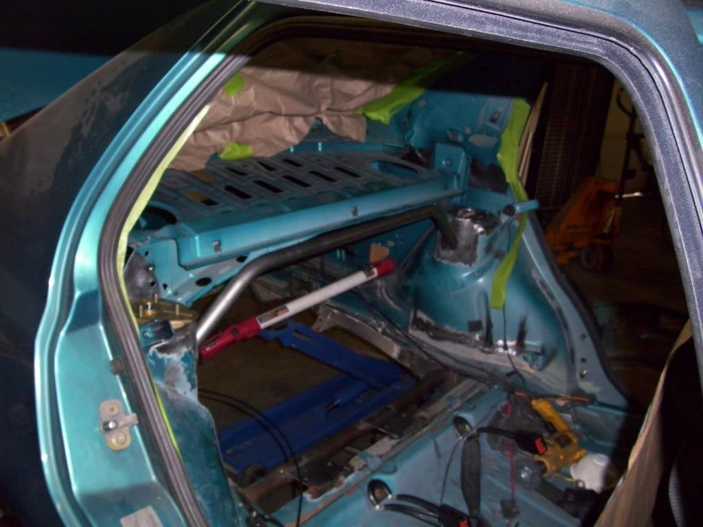
So I bent up another one
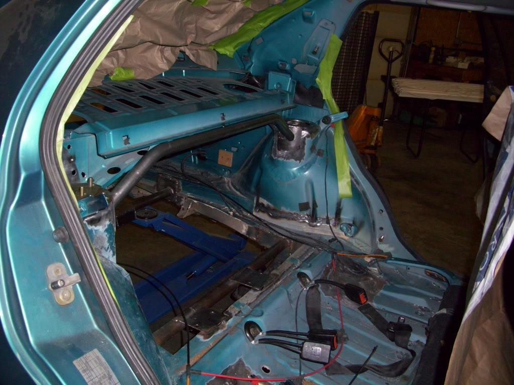
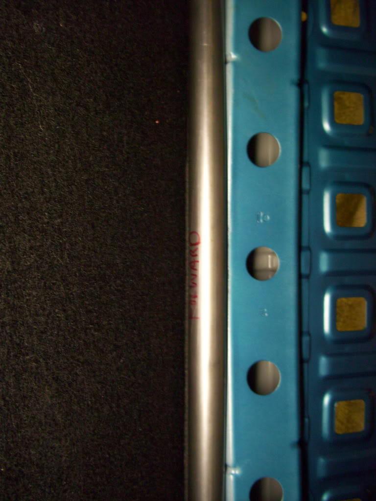
The angle matched good enough that with carpeting, this will all be hidden. Keep all the wild stuff under the skin.
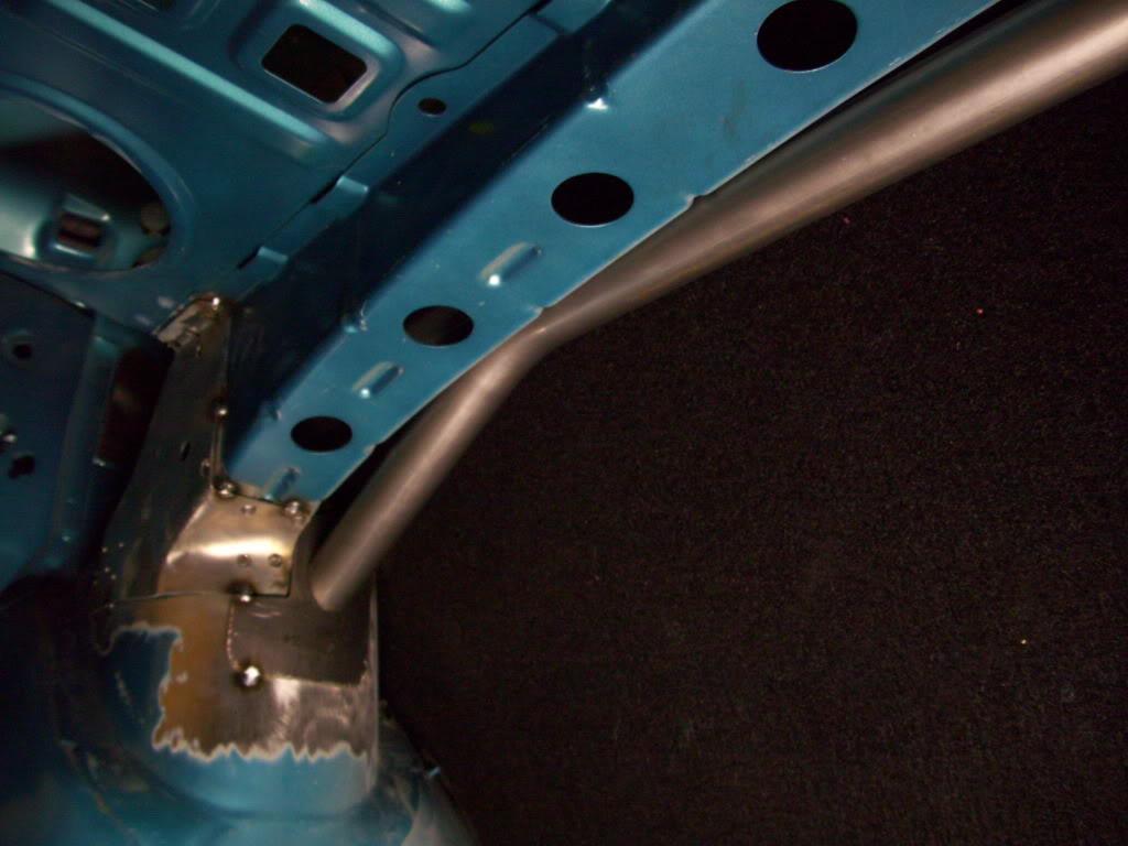
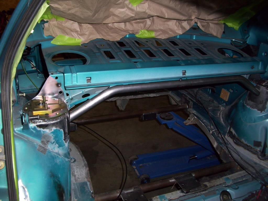
The brace will be welded to the rear shelf to maximize the stiffness of the whole unit. It was kept close so I could weld right to it without additional plates.
May 25, 2009
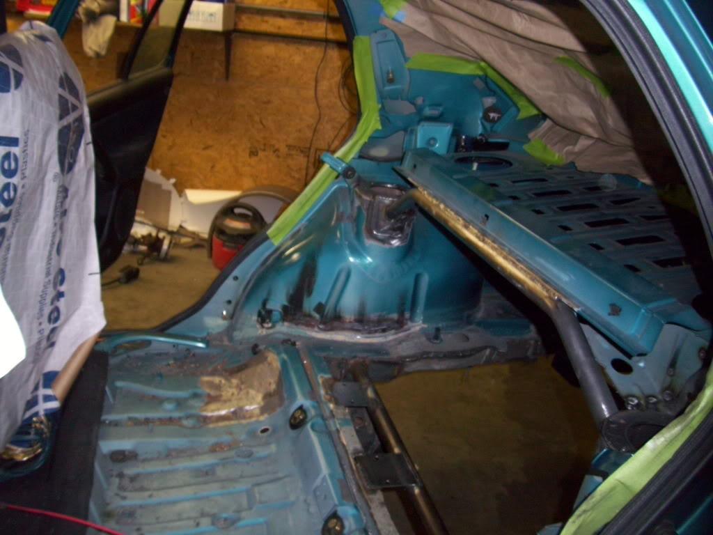
I welded gussets into the corners of the tower braces, connecting it fully into the existing rear shelf. Taking advantage of the existing metal, I was able to maximize the stiffness of the rear end while adding minimal additional steel/weight.
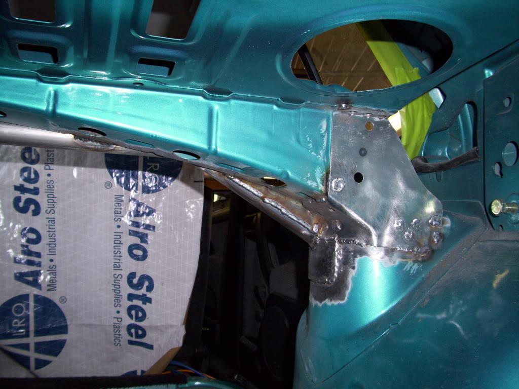
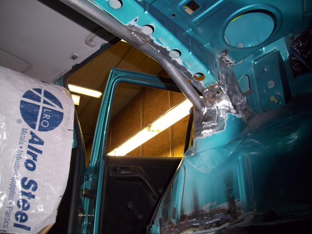
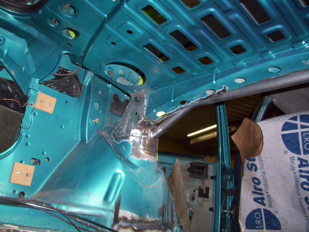
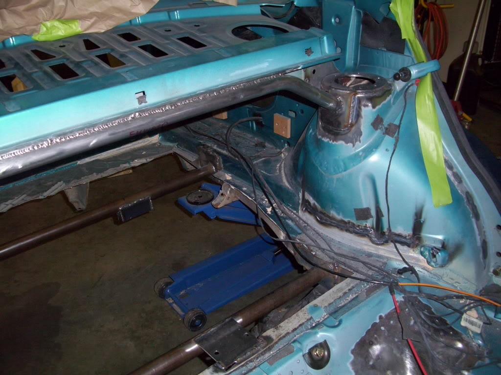
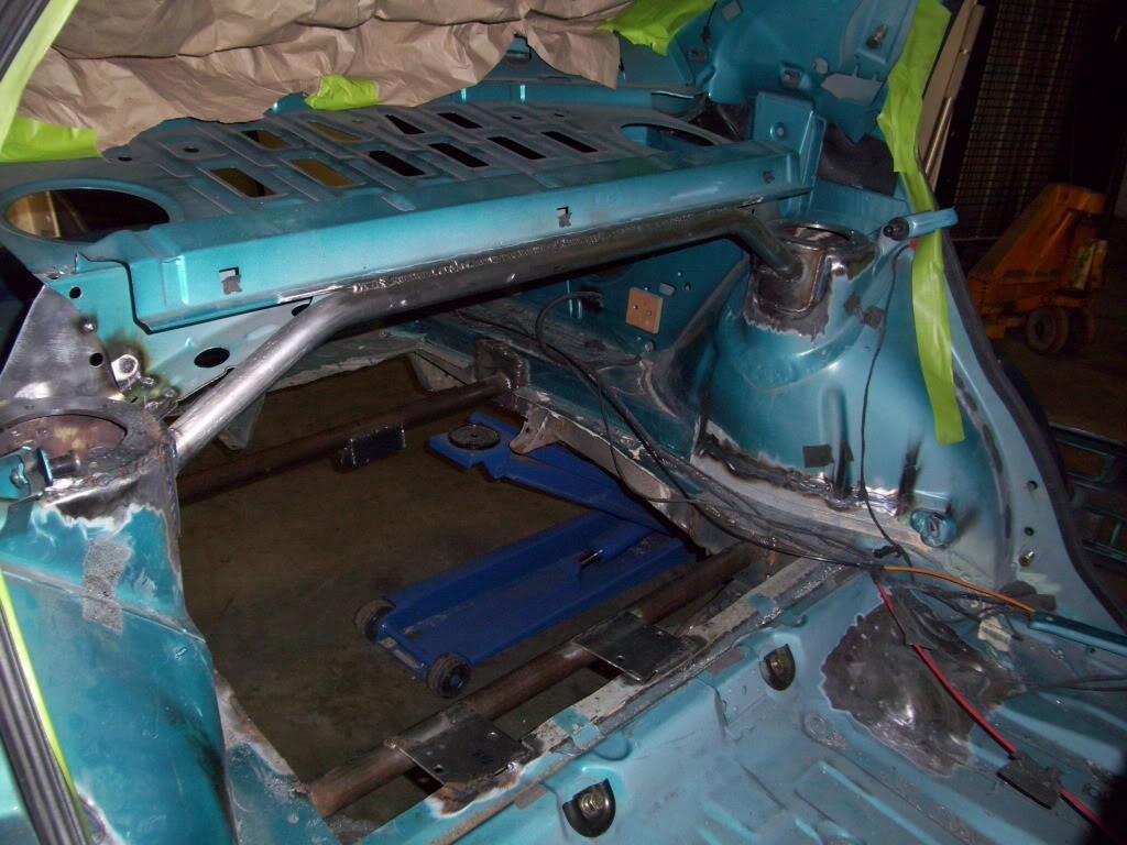
I also welded all the way across the top of the tower brace
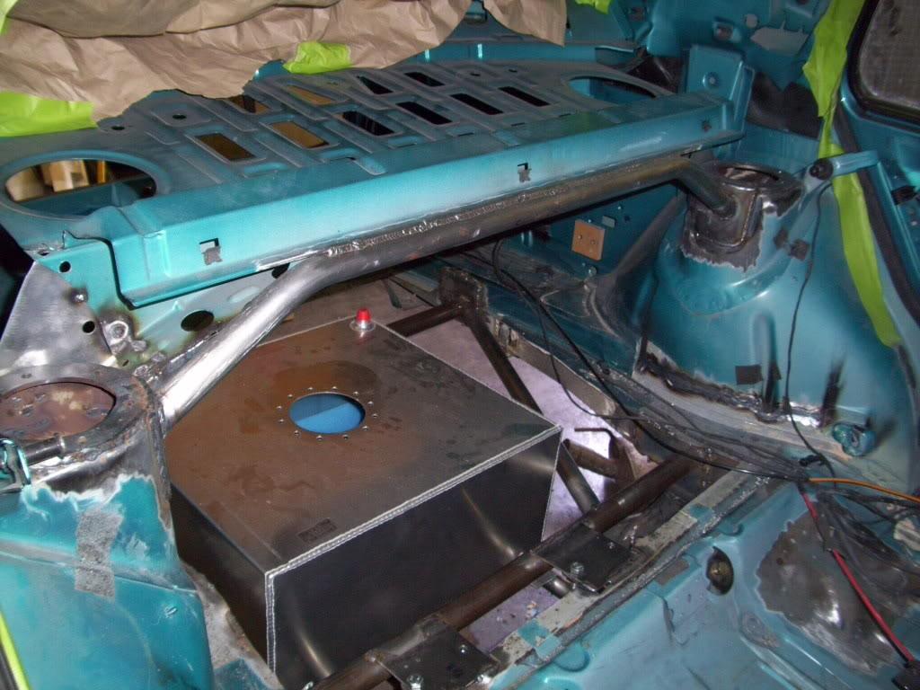
I added a tubular diagonal connecting the two rear floor crossmembers to add a bit of stiffness toward the rear of the car without interfering with the fuel cell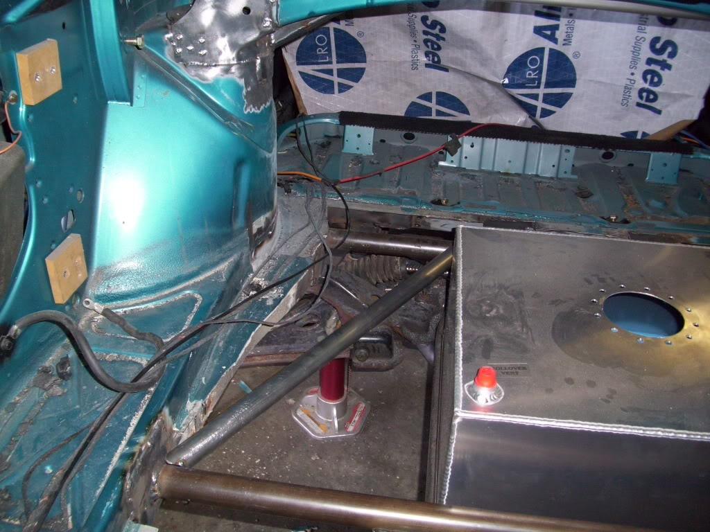
May 30, 2009
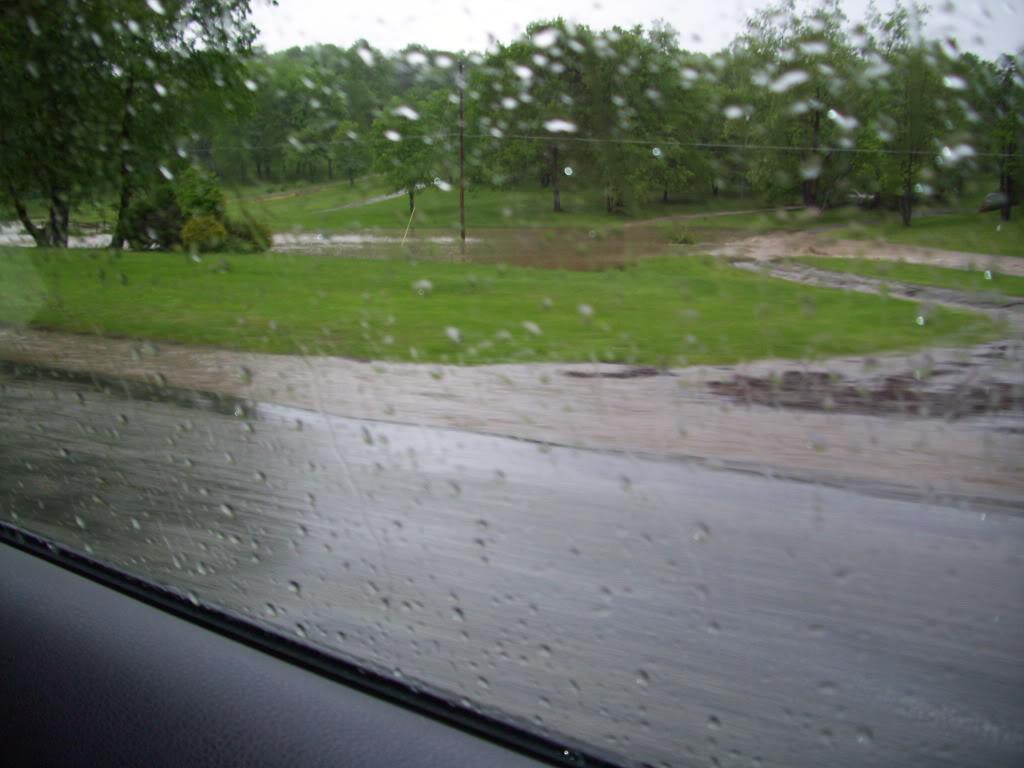
Heavy rains! I don't normally pass a river on my way to the garage
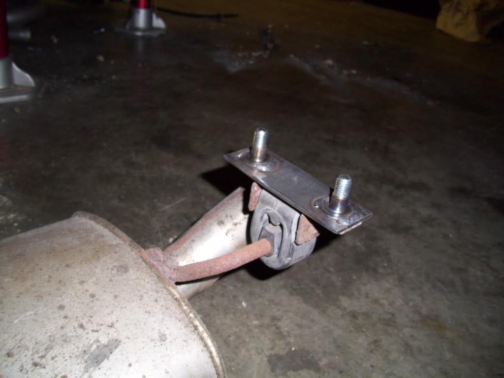
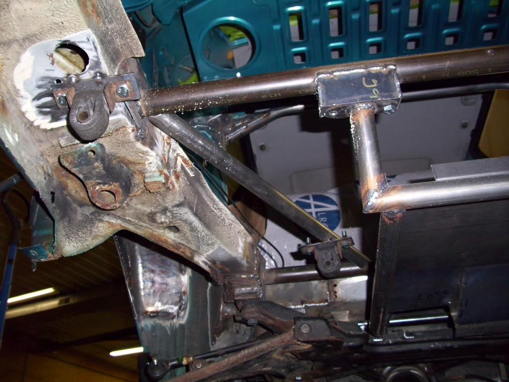
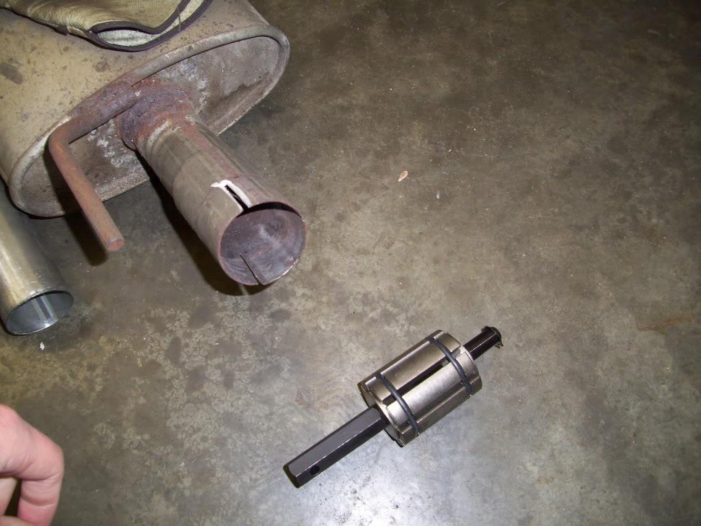
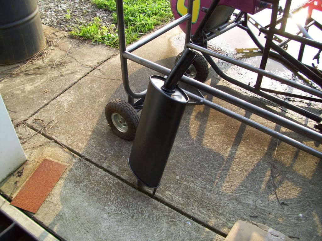
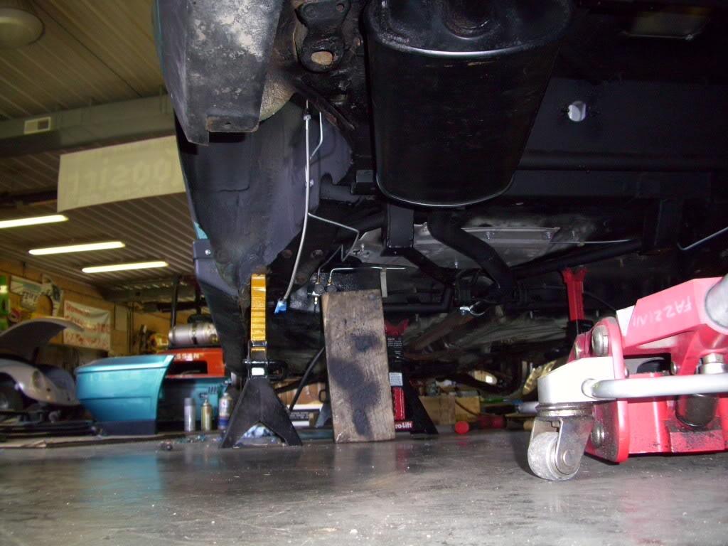
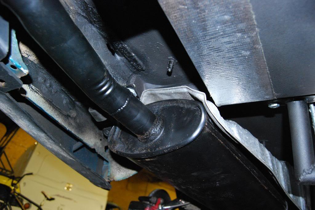
I wanted a quiet exhaust, and the budget is already running thin, so I decided to use the stock muffler. This also gives me flexibility when choosing a future muffler; anything that fits a stock jetta! I made some mountings to weld into the chassis for the hangers.
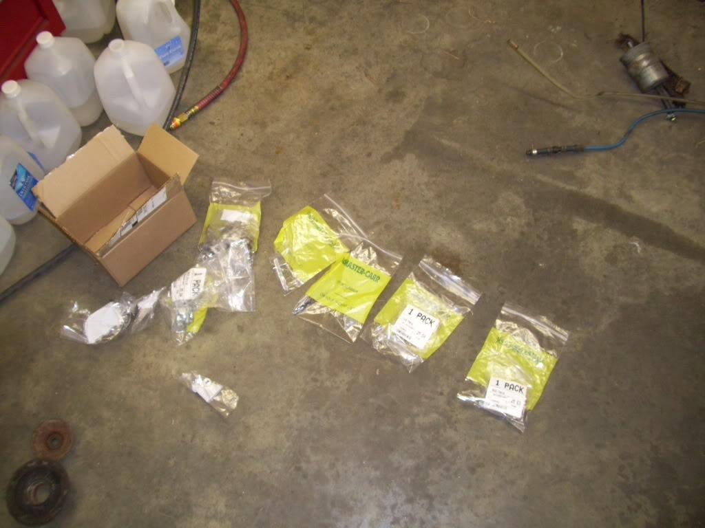
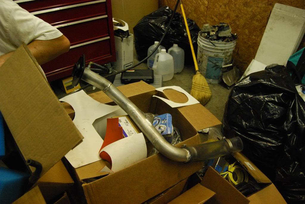
I got some of the parts for the custom fillerneck.
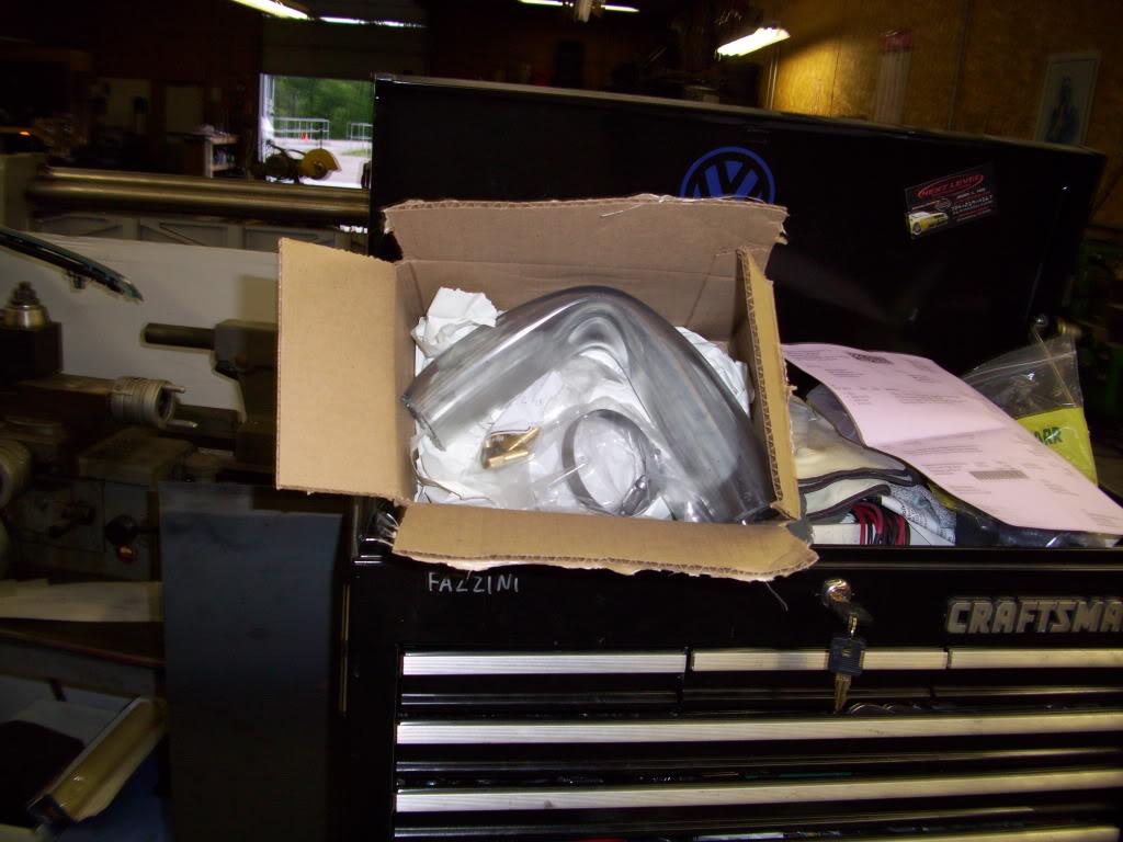
Tygon tubing for the flexible coupler between the tank and neck... nicely packaged
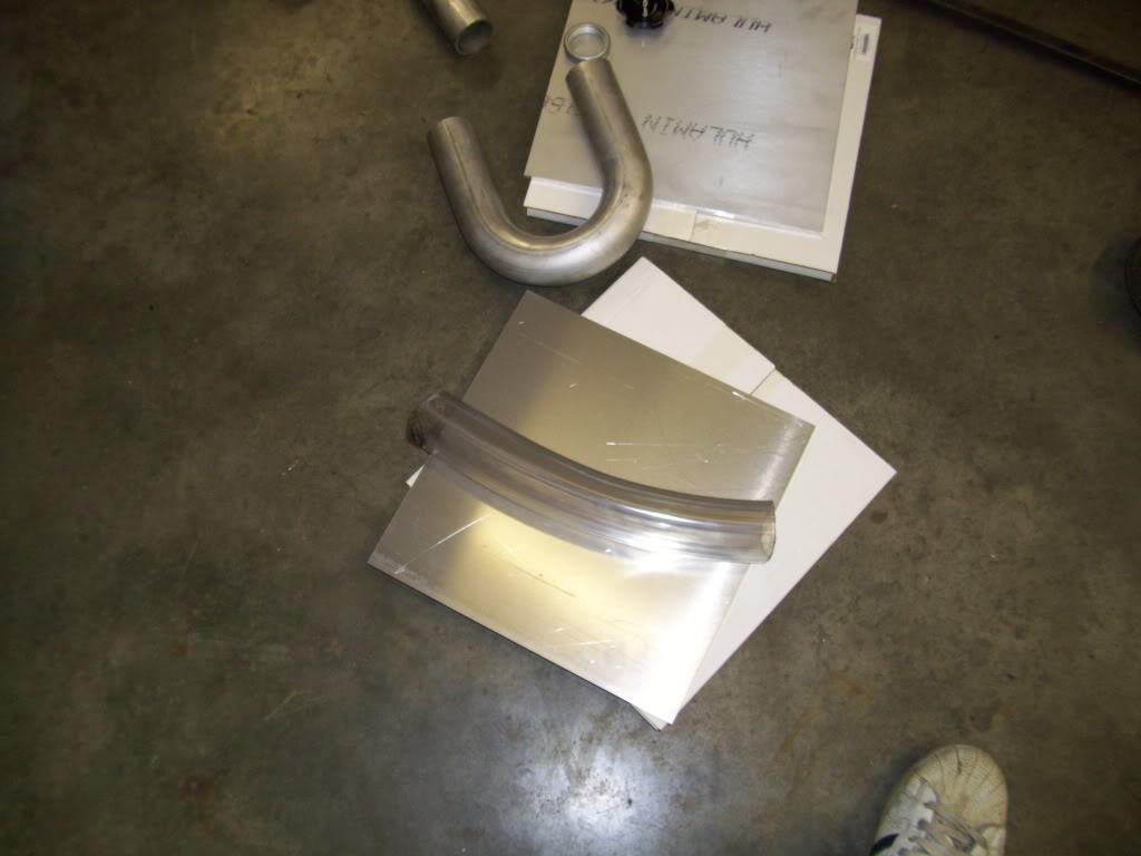
This is all 6061 Aluminum
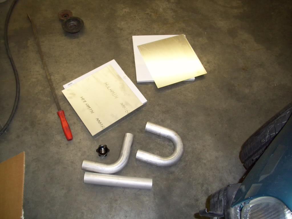
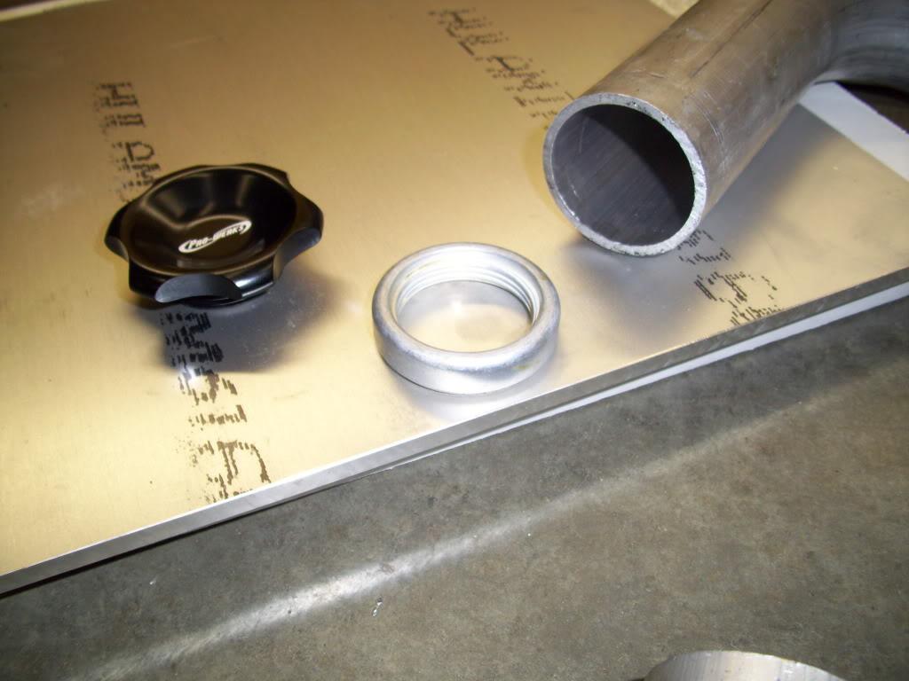
The McMaster-Carr supply company is beyond badass.
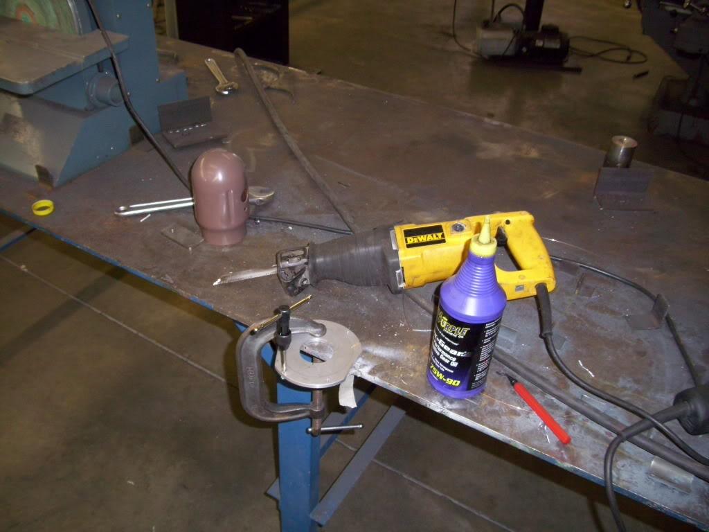
I decided to cut out the stock fuel ports in the tank, which I wouldn't be using anyway
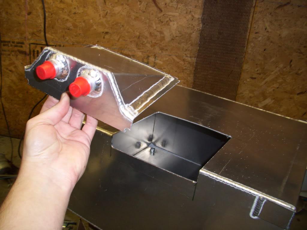
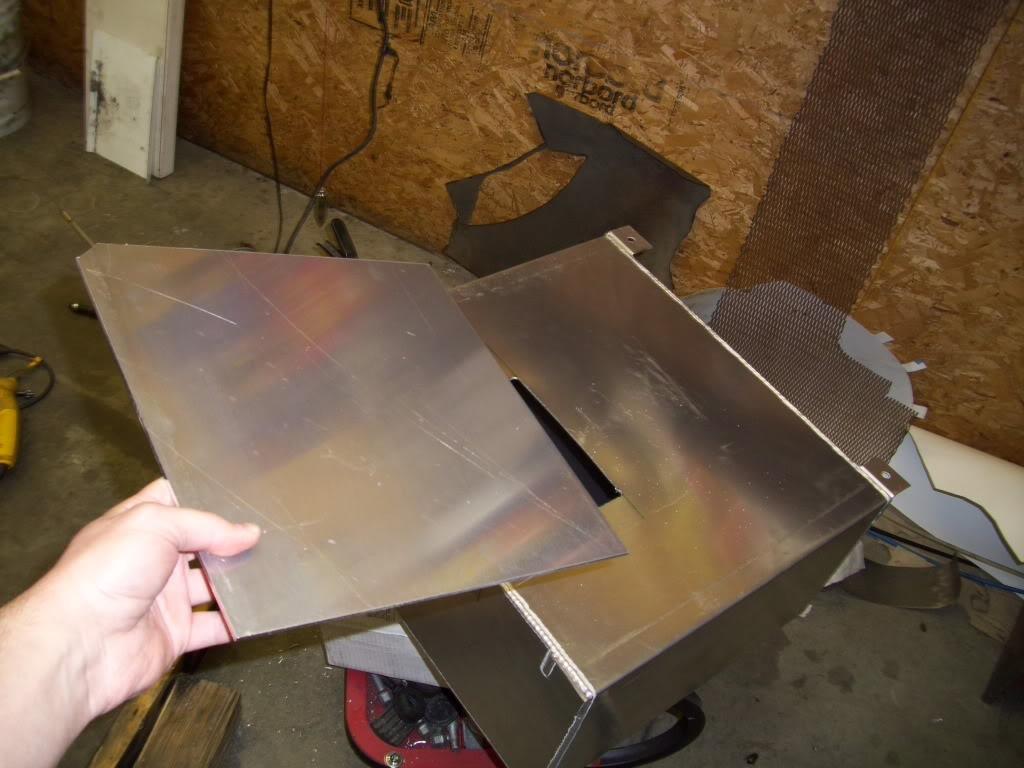
And made a filler plate
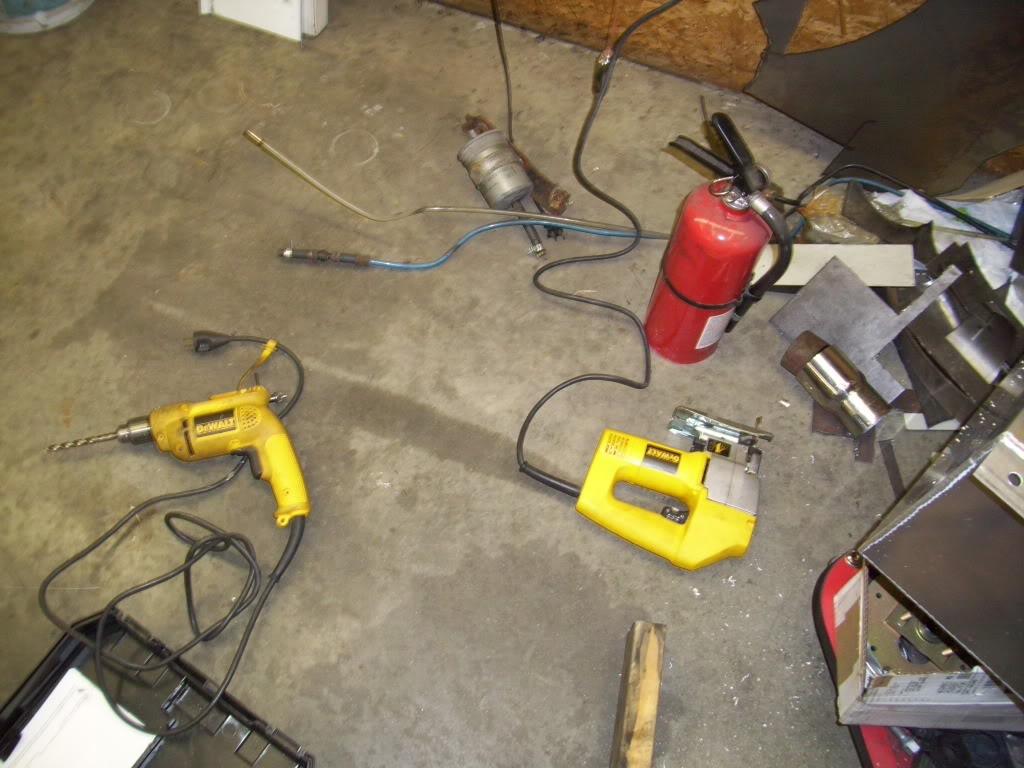
This is my CNC mill
May 31, 2009
I did some work on the custom filler neck and mounts

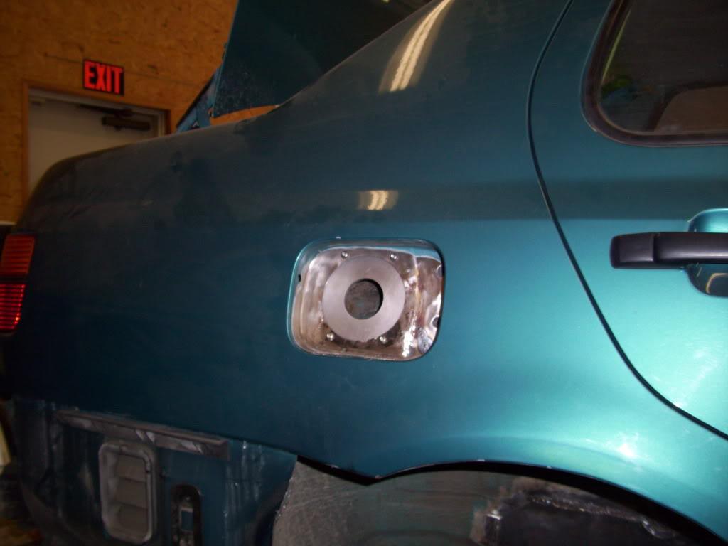
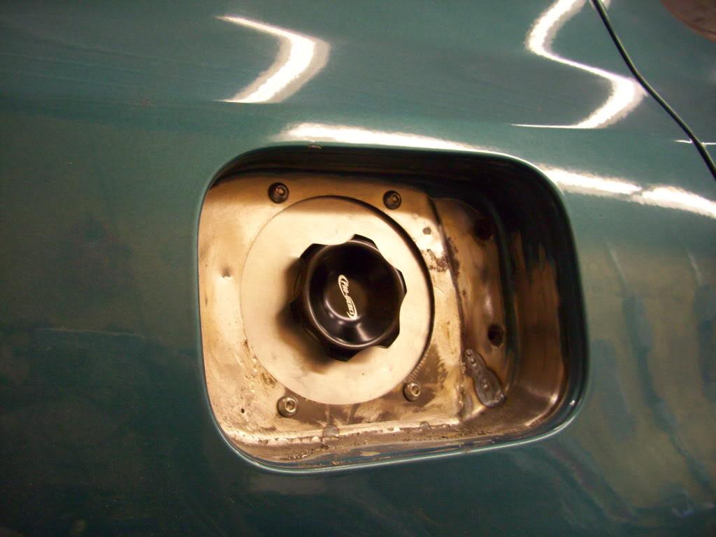
I removed the stock filler neck mounting bracket
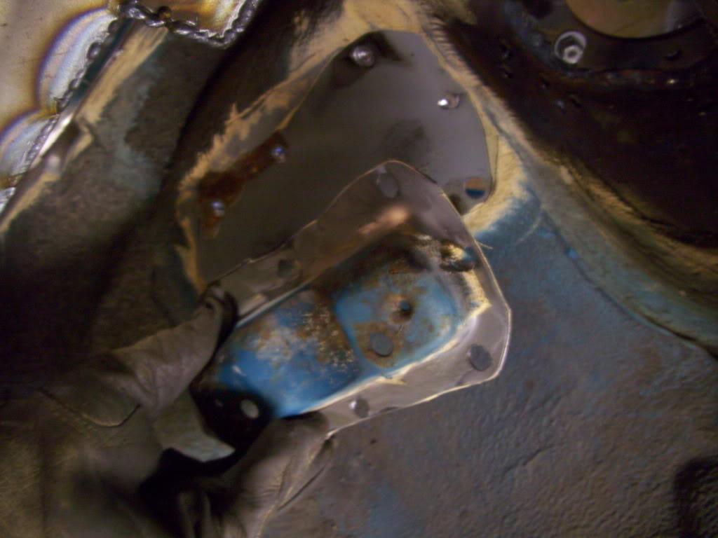
June 4, 2009
More fillerneck work!
Gaskets, weld-in plugs, weld nuts
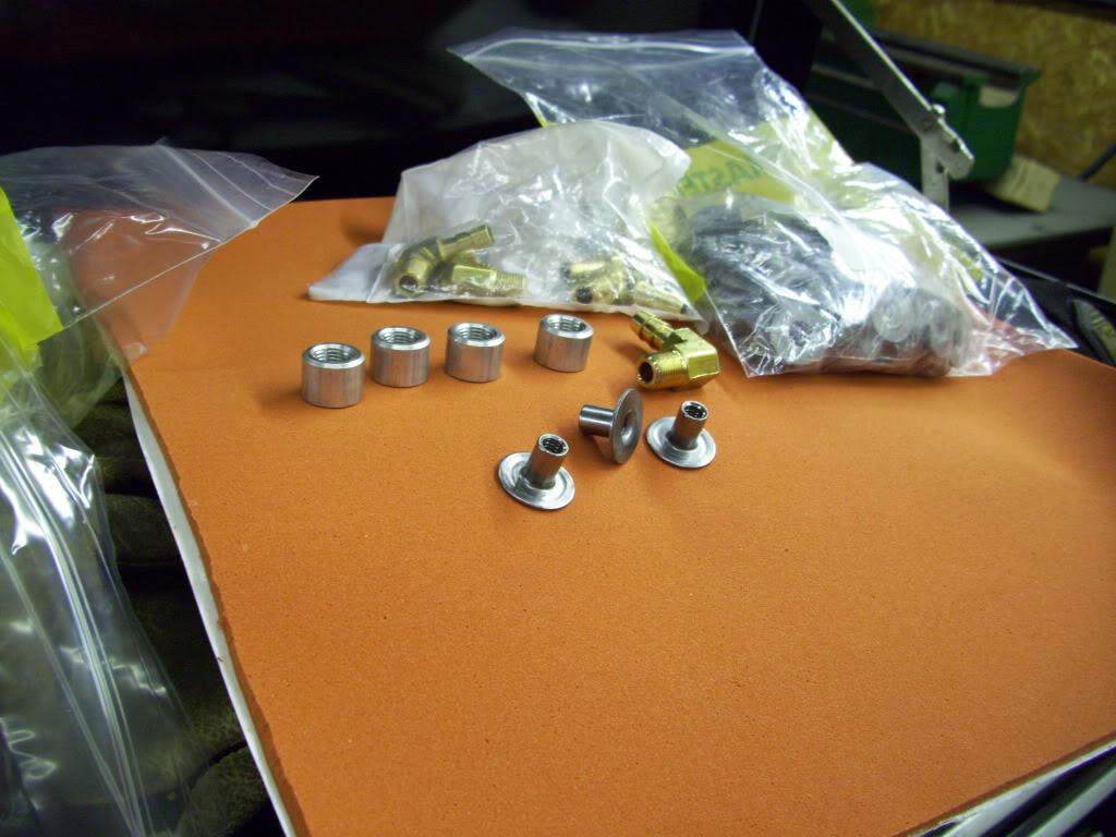
This process was a bit awkward because I can't TIG weld Aluminum. I had to have my buddy tack it one piece at a time, or use tape and mark everything and just hope it all lined up! Unlike steel, where I could tack and move on, so the process was a bit slower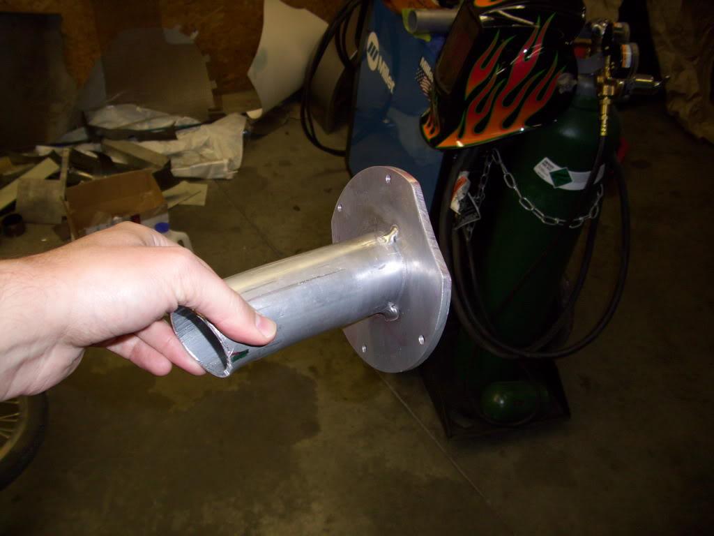
So I cut up the u-bends and made it fit around the tire... barely!
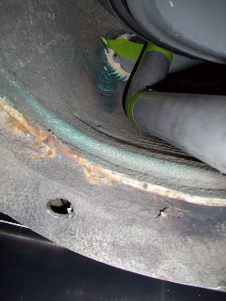
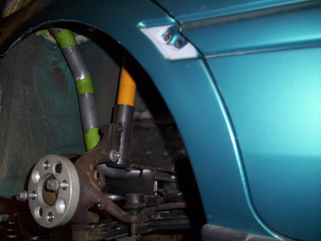
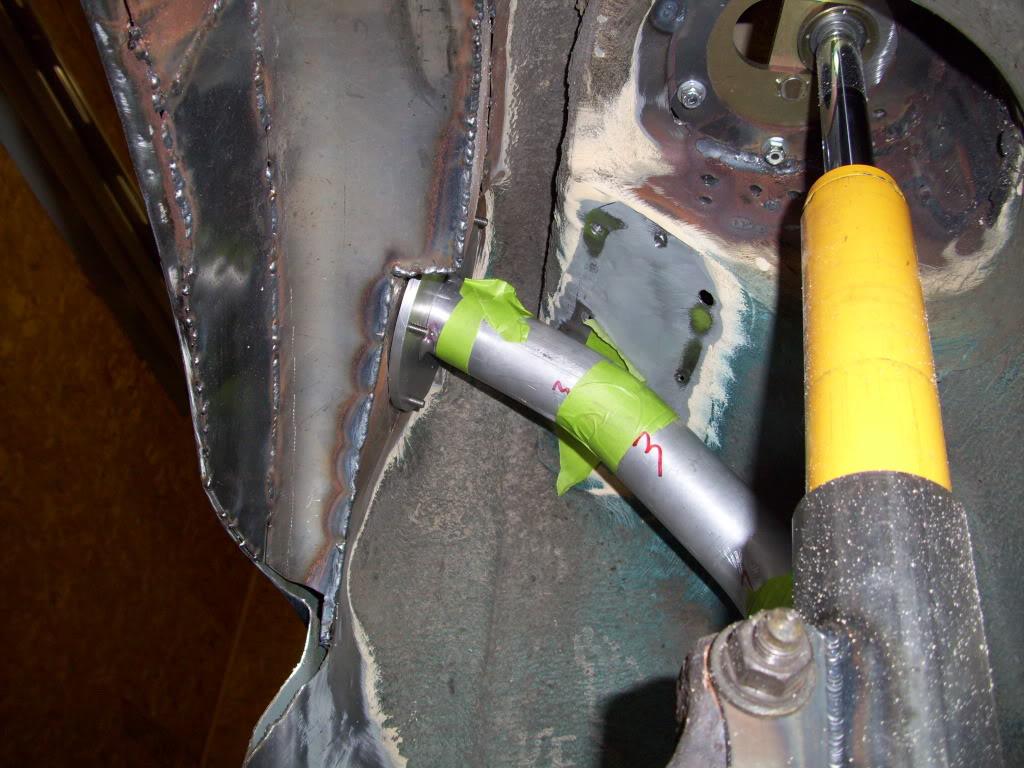
Vent hose ports come off the top of the fillerneck
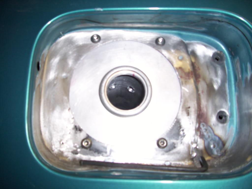
All taped up and ready for welding!
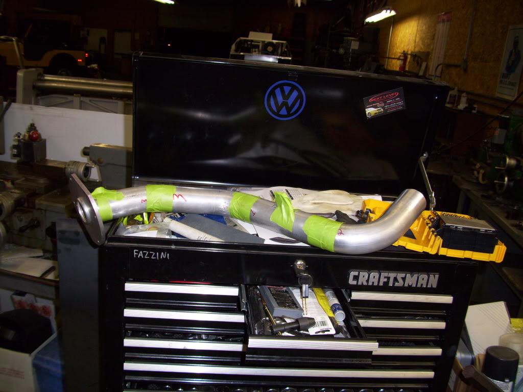
May 7, 2009
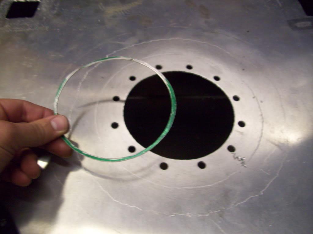
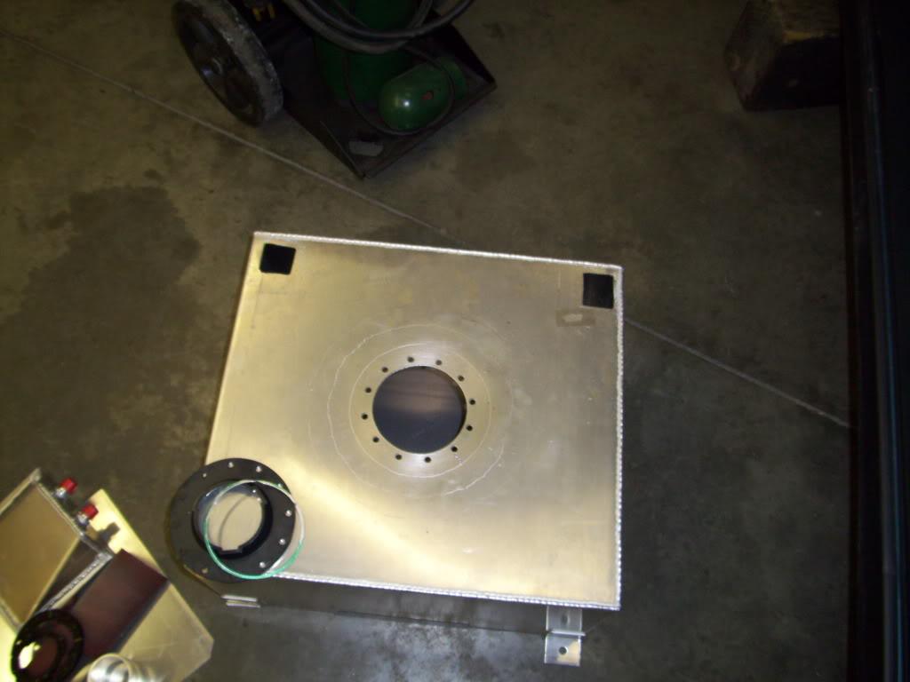
More tank mods! I had to enlarge the hole in the tank for the fuel pump to fit through
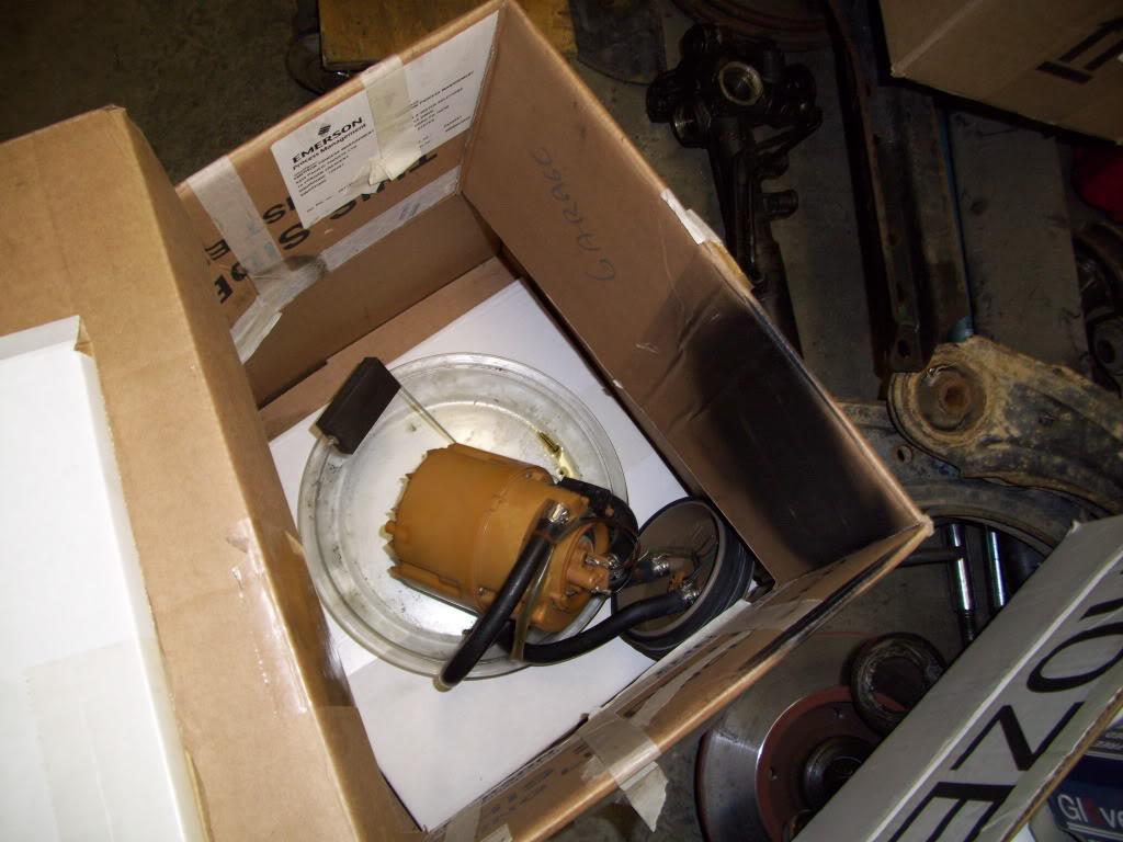
Stock fuel pump:
This ring is bonded to the bottom of a stock tank, so I cut it out:
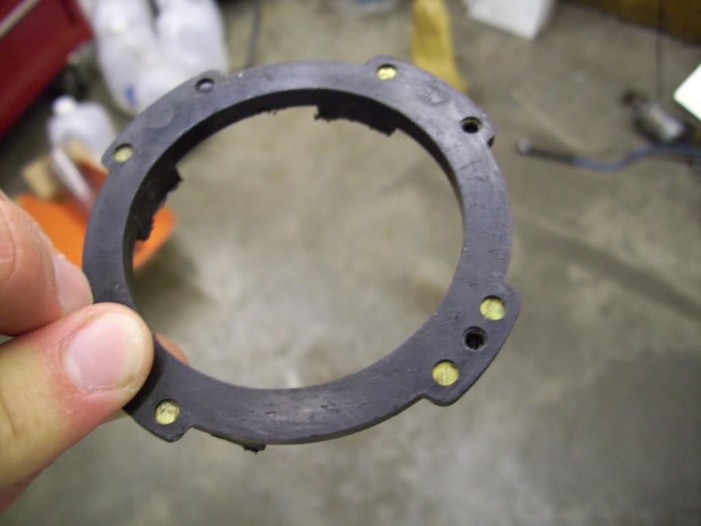
And this ring is bolted to the bottom of the stock fuel pump, so I unscrewed it
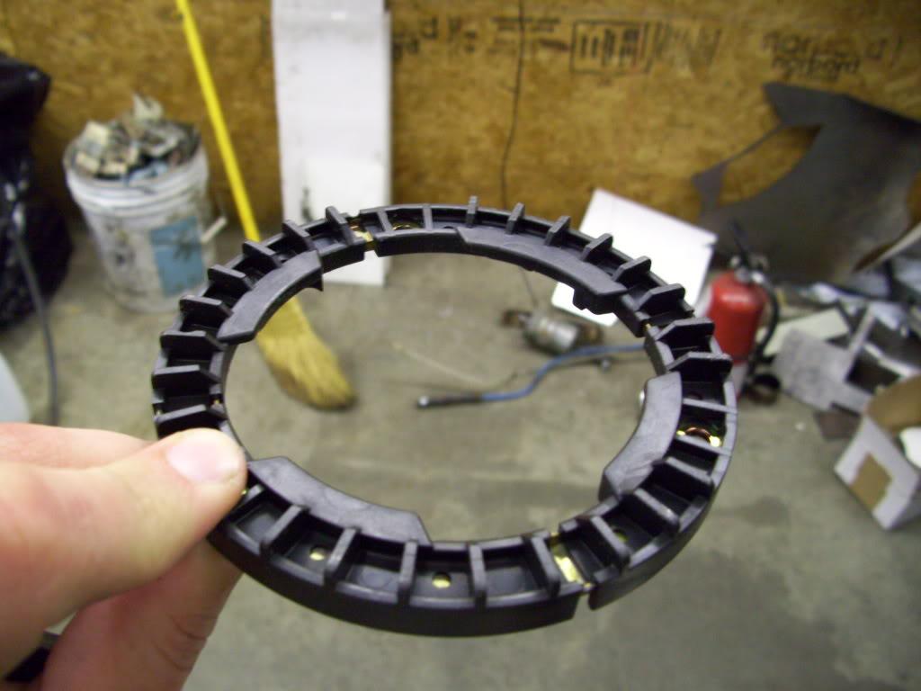
They lock together like this.

June 11, 2009
I cut some more patch panels for the fuel cell. I had to fill the gap at the bottom where I deleted the factory supply ports, and I also decided to plug the factory drain and return line. The tank was designed to be mounted in a trunk, and gravity feed down to an inline fuel pump (carb motors), then the return line and vent out the top. Since I'm mounting it below the trunk, with a remote vent, and an in-tank pump, all that crap needs to move. I should have just built my own damn tank
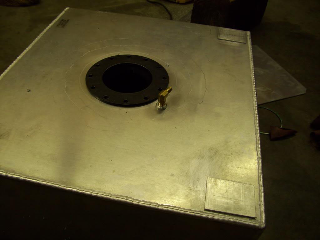
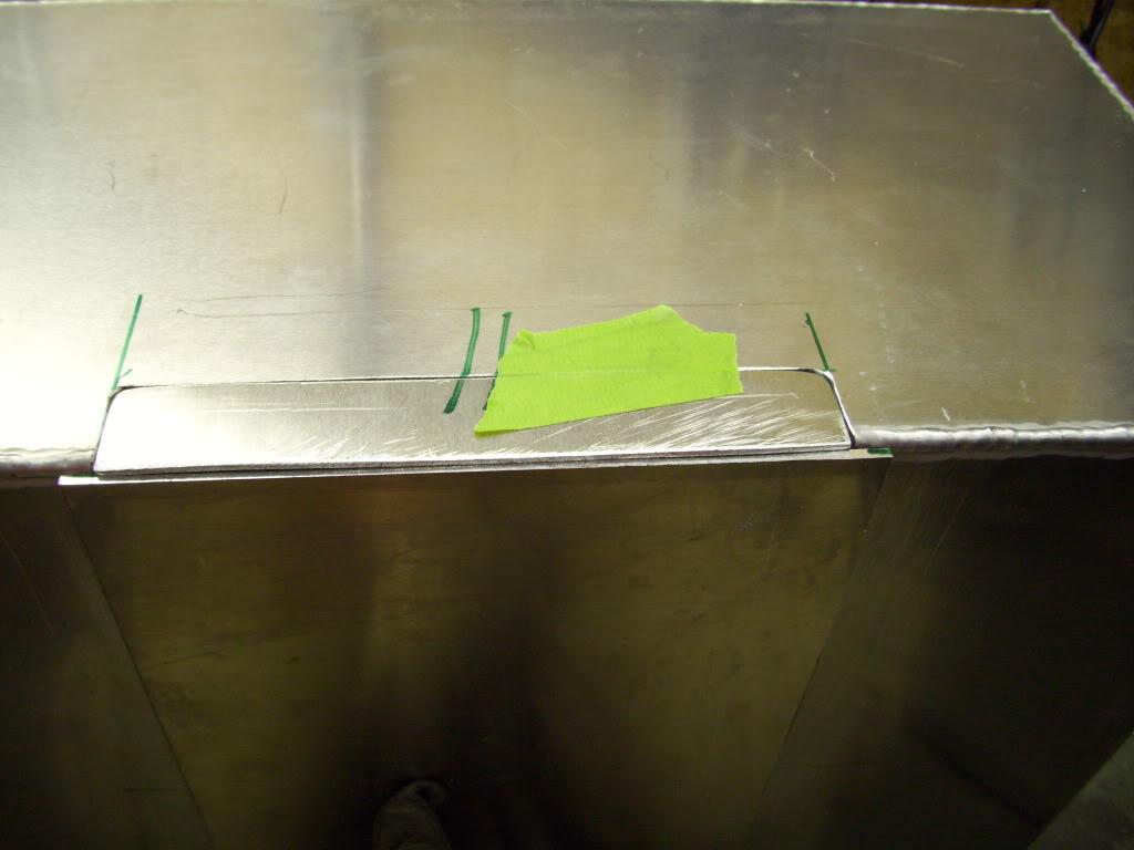
My friend welded up the aluminum fillerneck for me, and it turned out great! He's a pretty good TIG welder. This is one of the very few parts I didn't make myself
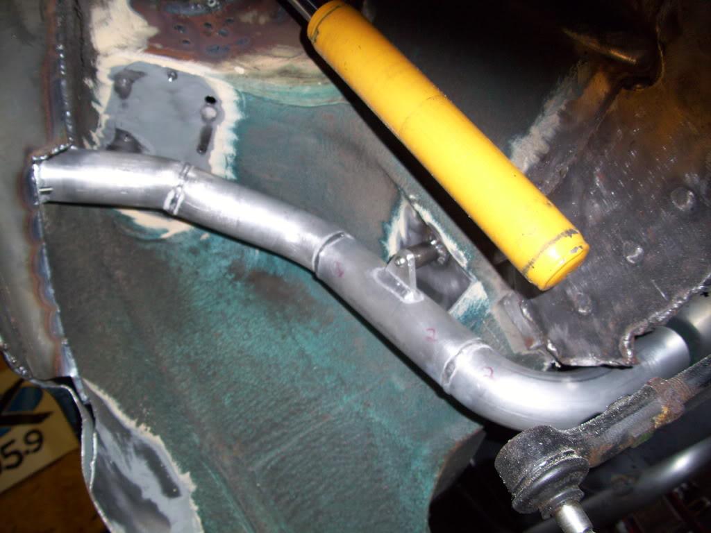
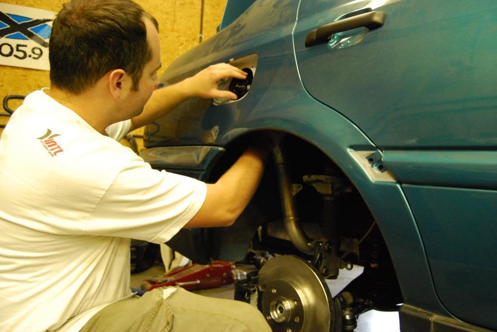
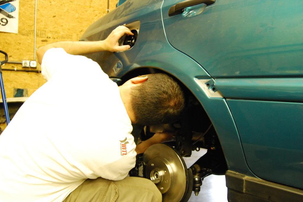
I welded this little bracket on the inner fender to support the center of the fillerneck. There is a little tab off the tube that screws into this boss.
Now I needed to figure out the brakes. I could run a front caliper and delete the ebrake, which as far as I know is how this has been done every time in the past. A lot of the mid-engine or rallye or race guys doing independent rears using VW fronts just use the hydraulic caliper with either a hydraulic or no ebrake. I wanted a mechanical parking brake, so I needed to use a rear caliper with the integral parking brake. This isn't a VW-specific type setup, so I looked into some other cars. I had a Nissan S14 rear caliper available, some Accord rear rotor parts, some Nissan S13 parts... All sorts of stuff that ended up not really working out. I would like to keep it in the VAG parts bin if possible, so I did a bit more research.
I initially wanted to run a 9-9-1/2" solid rotor, 10mm or 12mm thick, but couldnt find the right combo of parts I needed. Here I was comparing a mk3 stock front caliper (2.0, 10.1") to a stock mk3 rear caliper, and just trying to come up with some ideas.
Stock front:
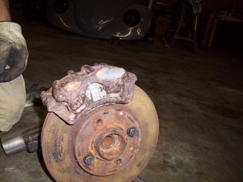
Comparison, stock front on left, stock rear on right:
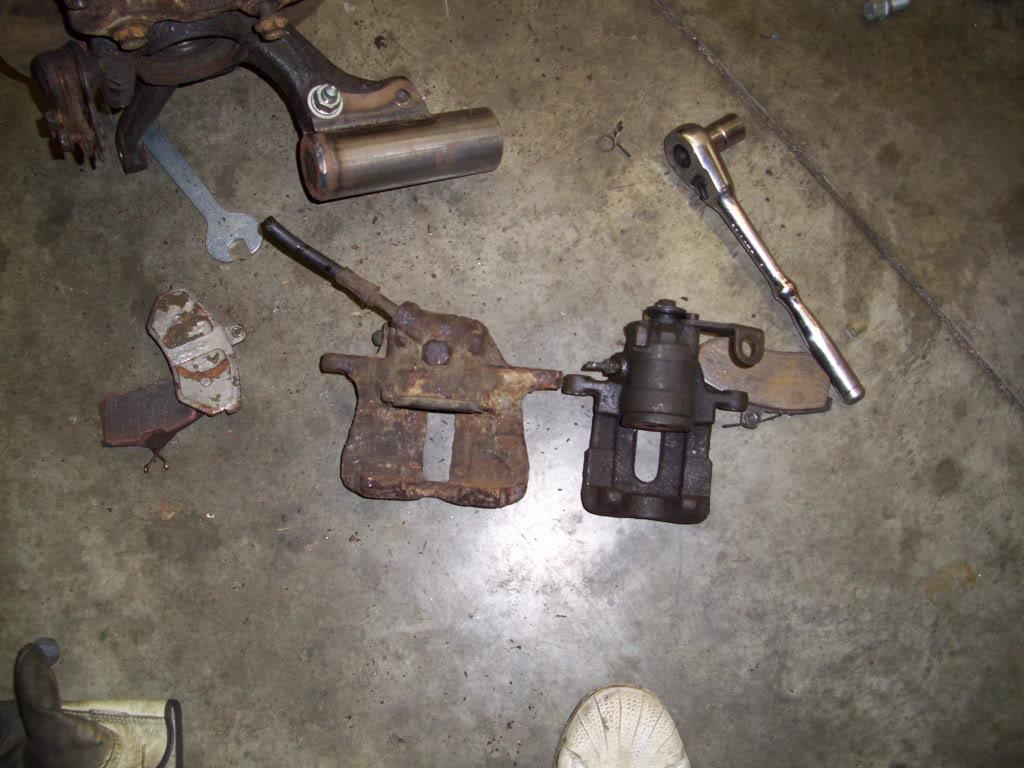
Here's a rear caliper on a front spindle, front carriers, front pads, front rotor.
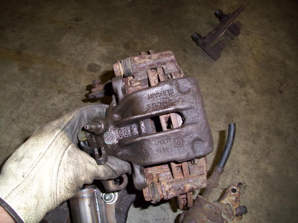
Maybe that will work? But the reach of the caliper isn't wide enough to use new pads with the 20mm thick vented front rotor.
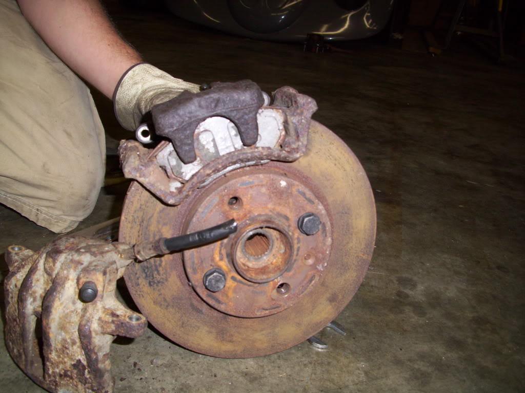
I gave up for the evening, armed with these pics and some ideas, and hit the books researching all sorts of rear brake options. Everything from A8's to coupe quattros to .:R32s and TTs.
June 13, 2009
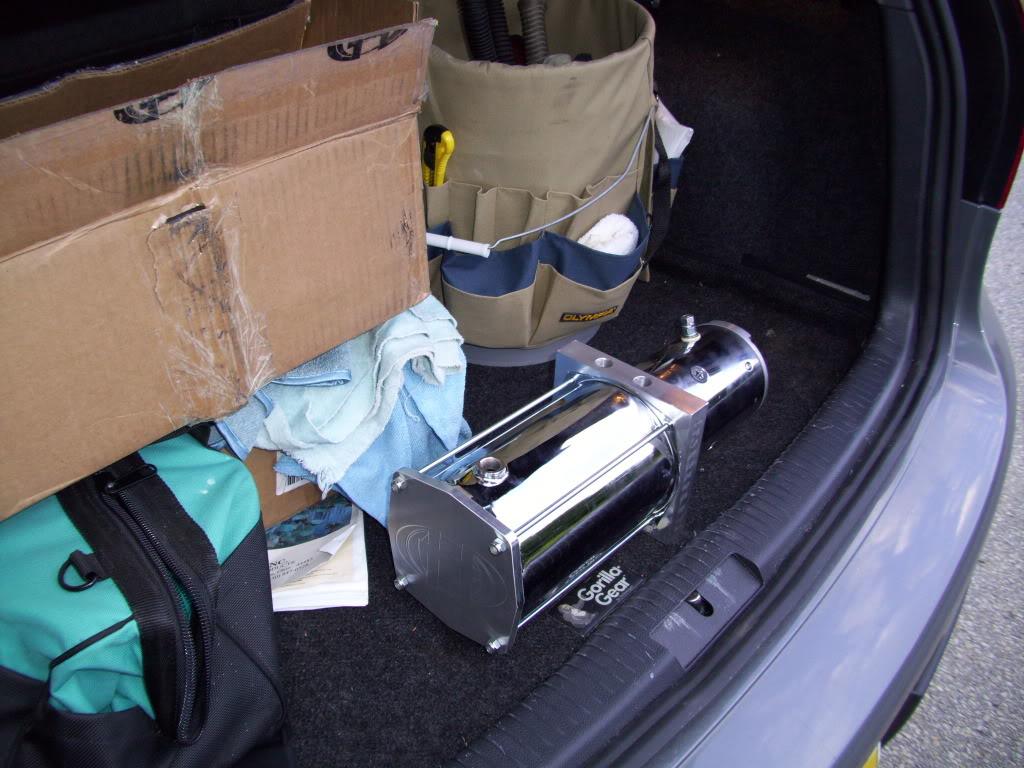
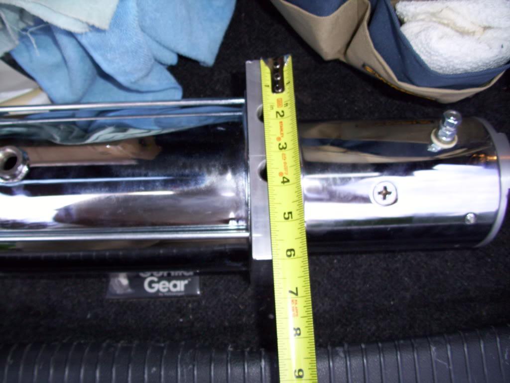
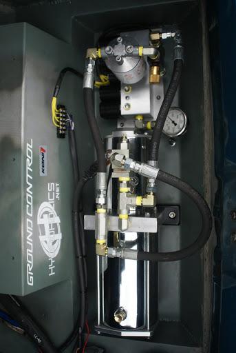
While figuring out the brakes, I made progress in other areas. The pump arrived from Hydroholics.net These guys are a new company, specializing in slow lift/lay hydraulic systems in midsize and fullsize cars. They're big into the VIP scene, they've even done a B7 Passat in Texas, some Lexus cars and a few SUVs and trucks. I decided to use their pump to run my custom hydraulic cylinders, as well as their 5-dump manifold. More on that later, but the pump arrived! I ordered it first so I would have it handy when building the trunk floor, just so I had every measurement I needed. It's a pretty nice piece!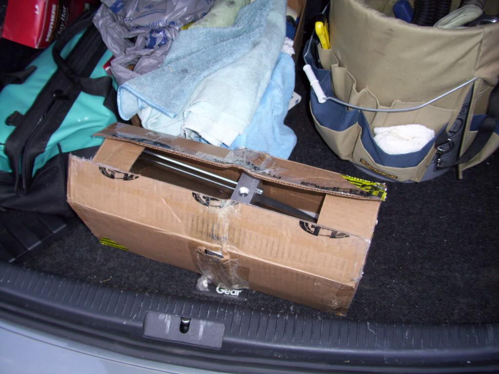
Remember that ring that was bonded down inside the stock tank? I needed to make a mount for it. I decided to make an Aluminum ring which would be welded to the bottom of the tank, with plenty of surface area to epoxy the stock plastic piece onto it. Then the two plastic pieces could lock together and the pump would be mounted to the bottom of the tank. I didn't come up with this idea entirely on my own, some dude building an MG used a stock mk3 jetta fuel pump and did this to mount it inside his steel tank. I stumbled into his build thread while google image searching for a picture of the fuel pump a few months prior to this. Great idea buddy if you ever read this lol!http://www.britishv8.org/MG/ScottCostanzo.htm I did it a lot differently, but he had some inspiring ideas.
I turned this piece on my lathe
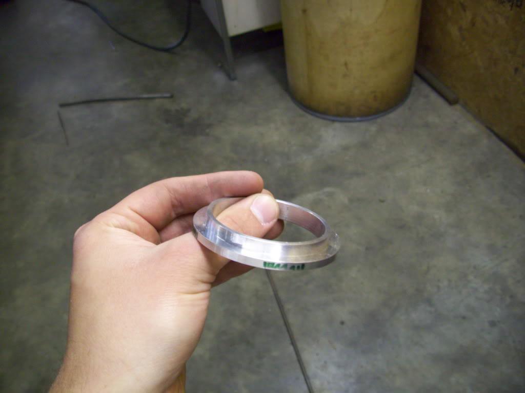
Then, believe it or not, I did the rest of this with a series of files. It took a few hours, but I didnt' have access to a mill and I wanted it done that evening. Not the most effecient or pretty way to do it, but it worked!
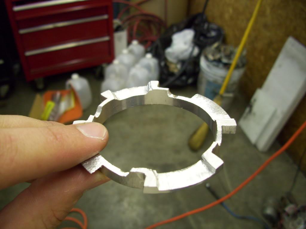
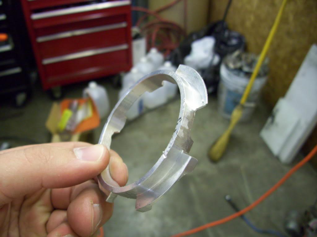
It fit snug down inside the plastic lock ring which was cut from the bottom of the stock fuel tank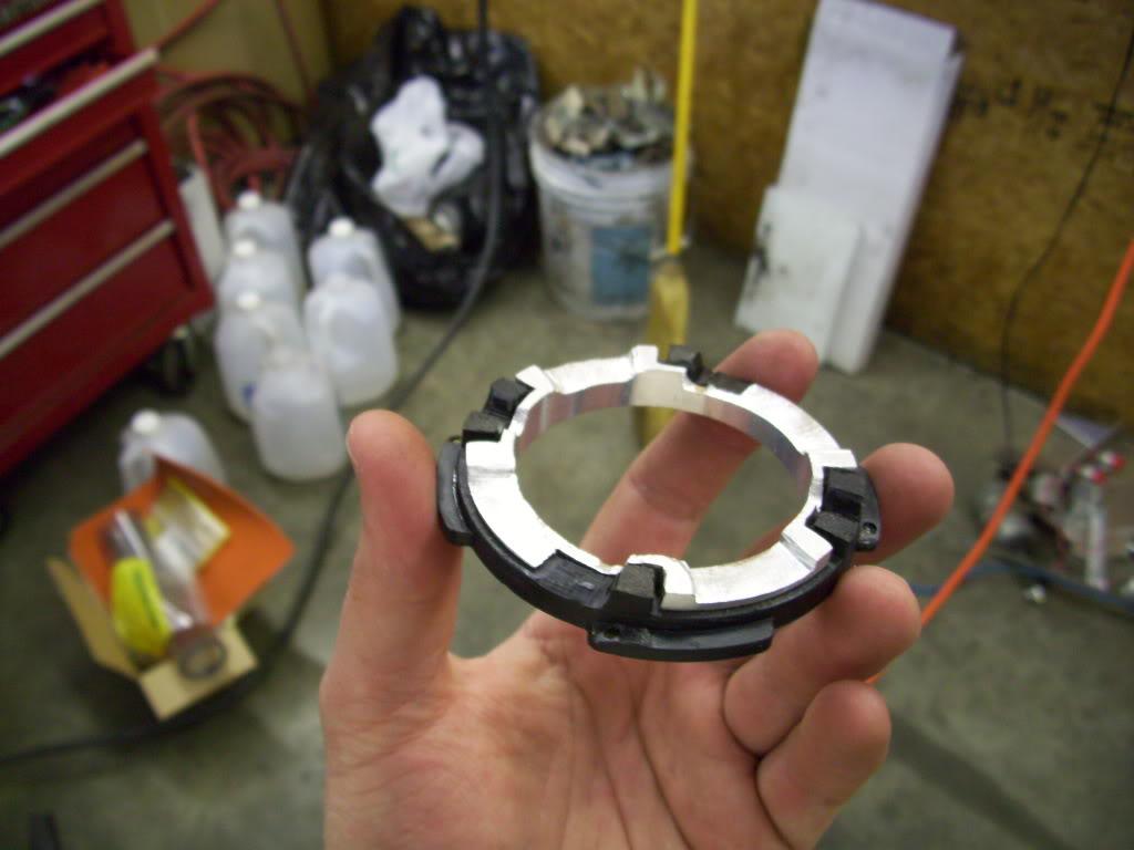
This is how it will sit in the bottom of the tank. I left some area to weld and it clears the fuel pump just fine, with proper spacing off the bottom of the tank floor. I even checked the flow capabilities on my highly technical flow bench, which some people call the "sink." Yay Science!!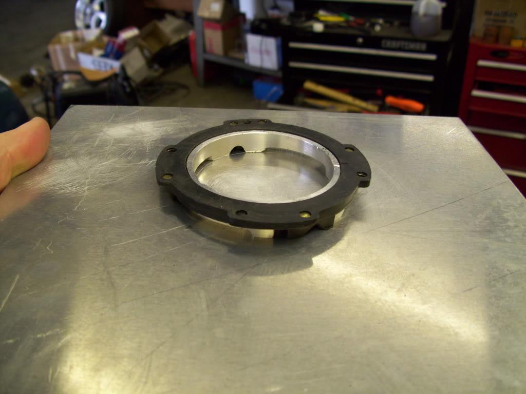
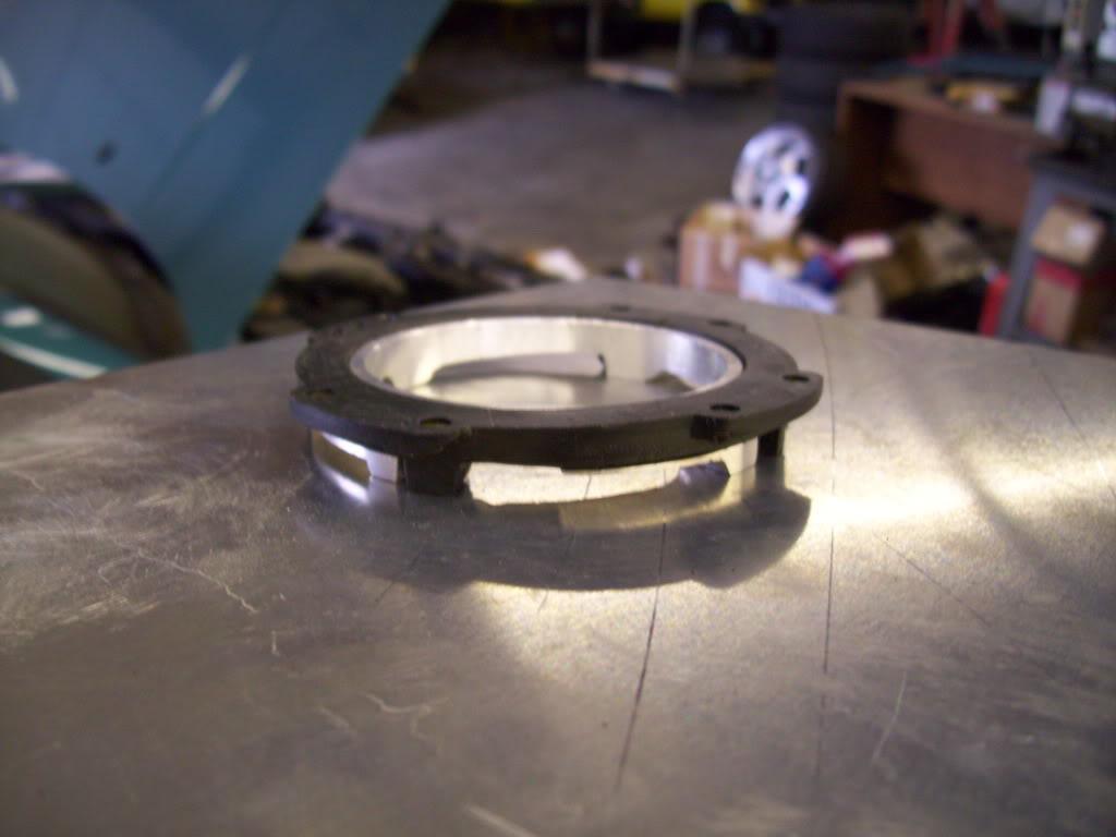
June 14, 2009
I needed to cut out the remainder of the stock trunk floor so I could start building the new sheet metal trunk floor and hydraulic pump mounts. Before I did this, I wanted to add one final cross member back near the rear bumper mounts.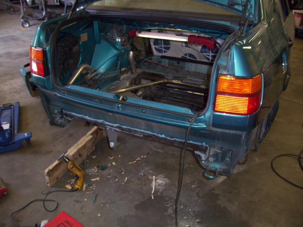
The stock center bumper bracket will be preserved, but later on.
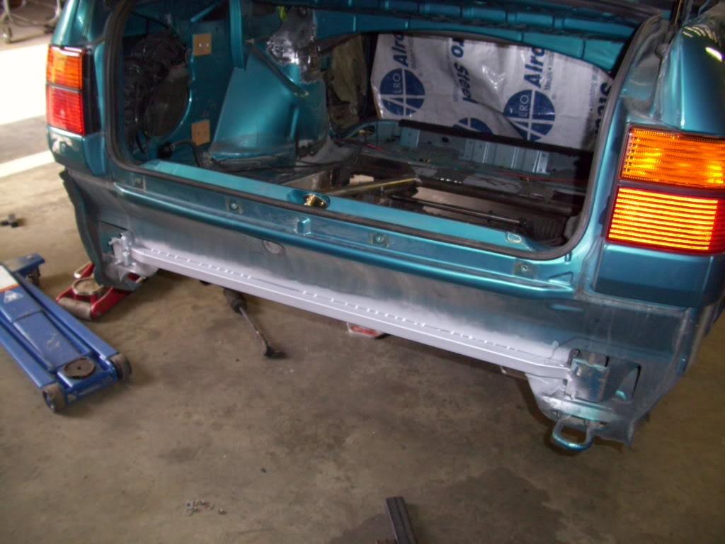
Then I chopped out the remaining metal
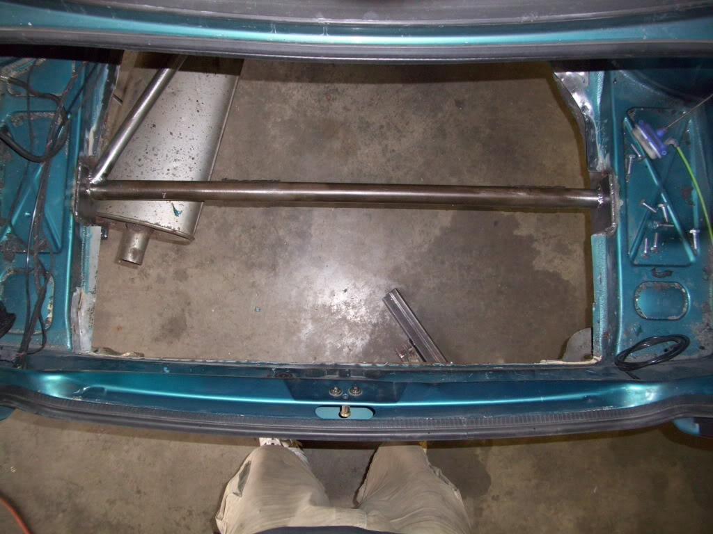
June 15, 2009
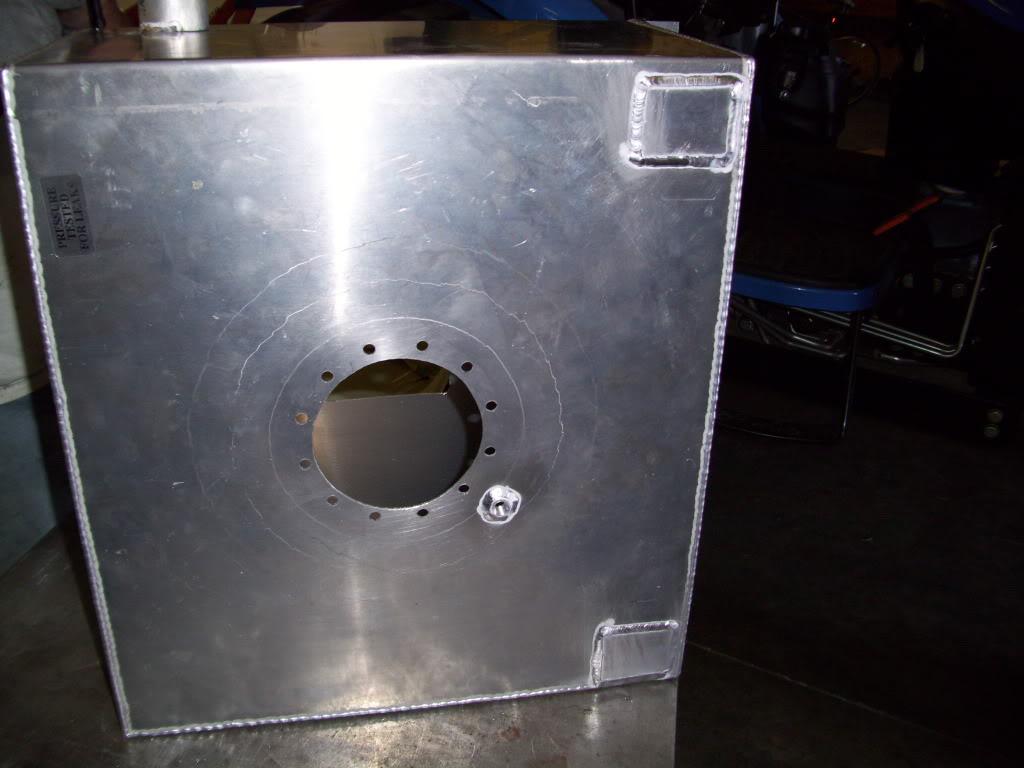
I got my friend Woody to weld up the fuel cell for me. He's the same guy that has been doing the AL TIG welding for me, he's pretty good! It was hard to weld the tank without warping, so it ended up warping a little bit, but still good enough and still sealed.
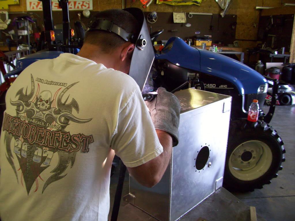
Mind if I try real quick?
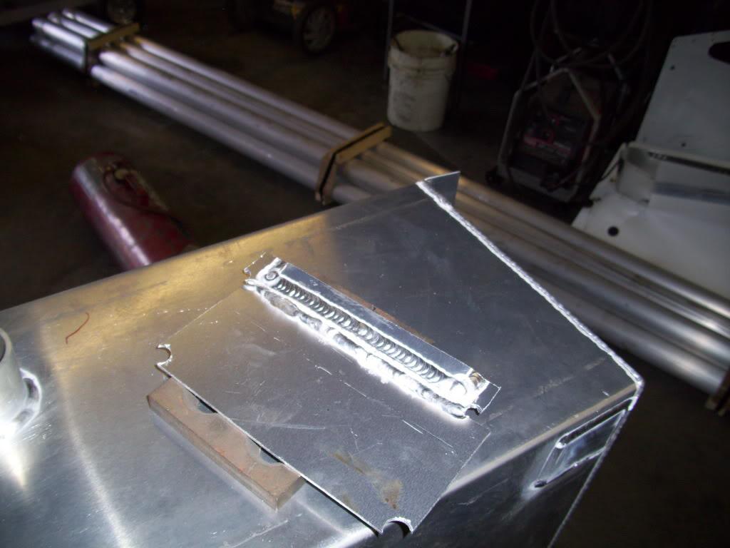
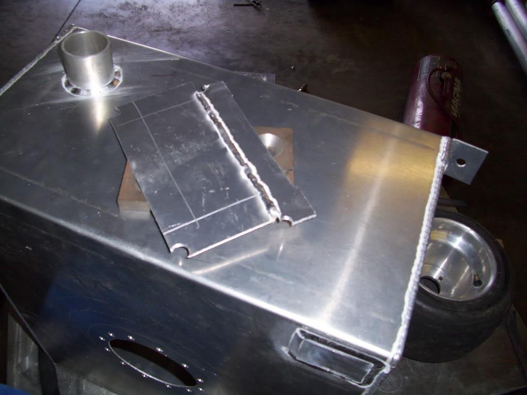
Not too shabby for a beginner like myself. But these were only practice pieces, I stayed away from the actual tank!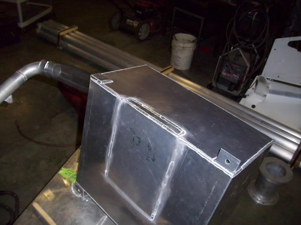
Pressure tested it, pass!
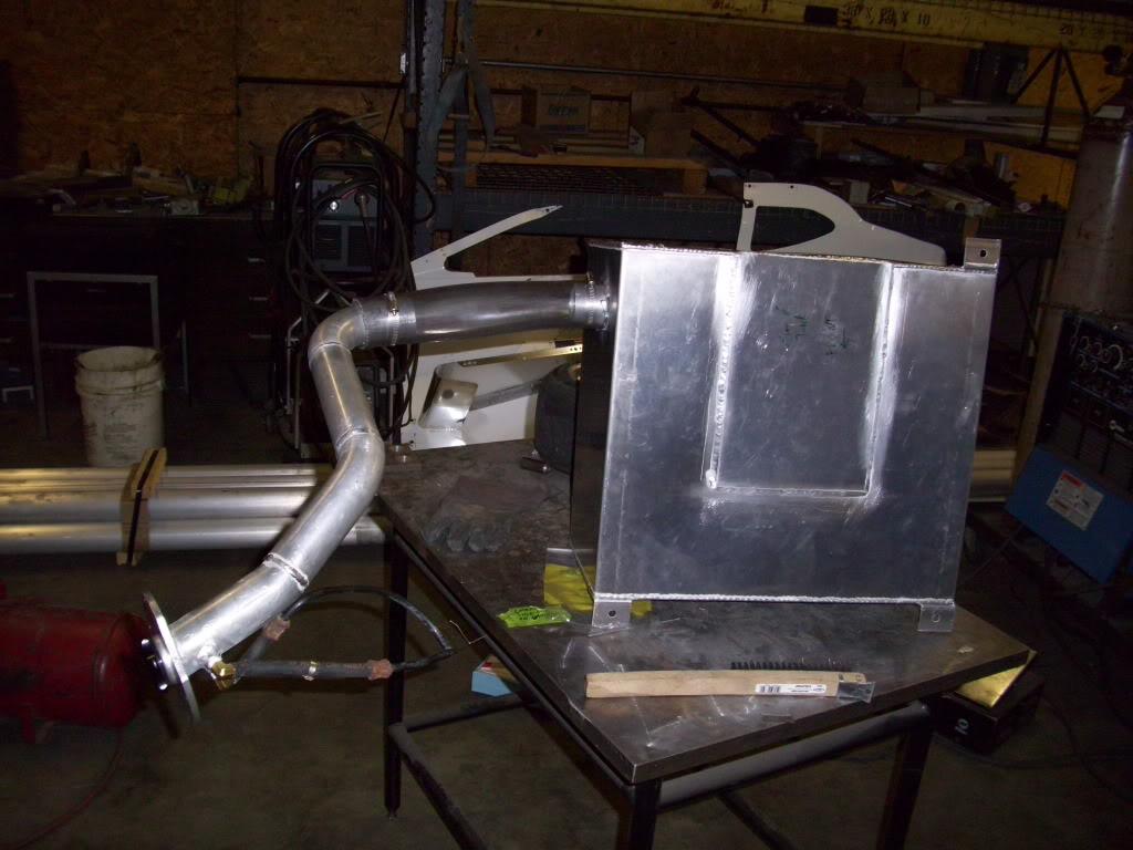
Then I did some planning about how the exhaust would be routed. Remember the funky shape in the left-side fuel tank support? That was for exhaust clearance and was planned in advance. I took a bunch of boring pictures like these so I could study them later and figure out the exact routing, and where each tube would go.
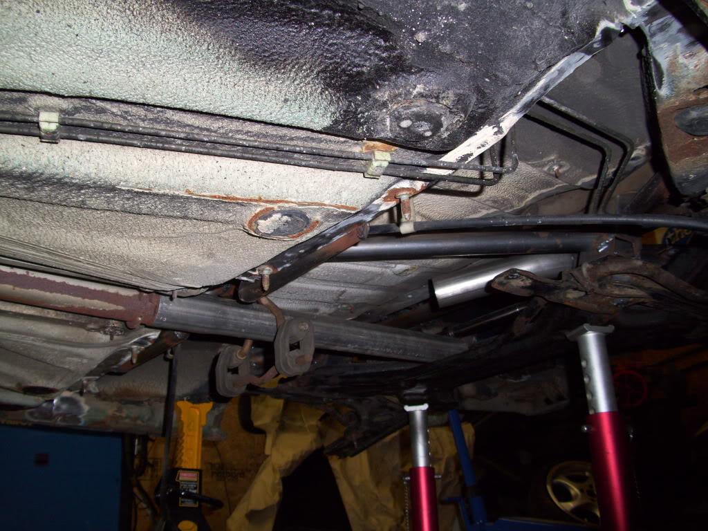
June 16, 2009
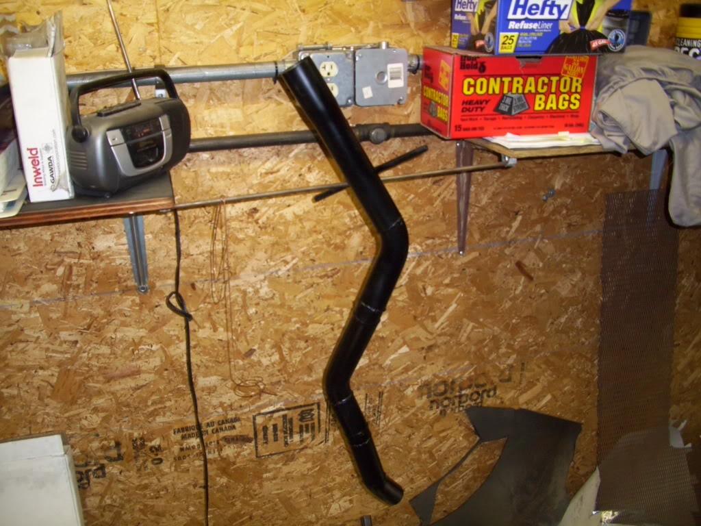
Exhaust is done! I absolutely hate working with exhaust. The only reason I did this myself is because the car couldn't drive under its own power to a professional exhaust shop. This will be redone in stainless sometime next spring, it is absolutely not up to my standards and one of my lest favorite parts of the build.
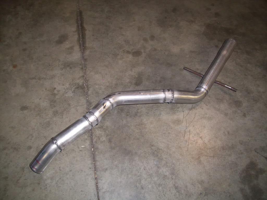
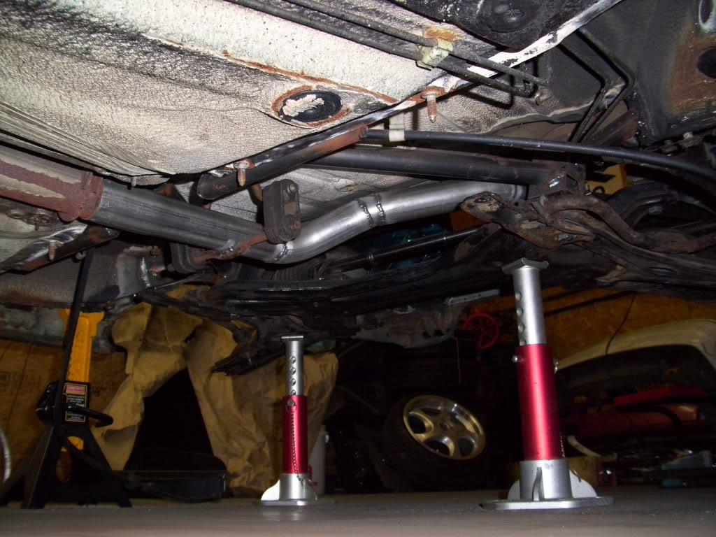
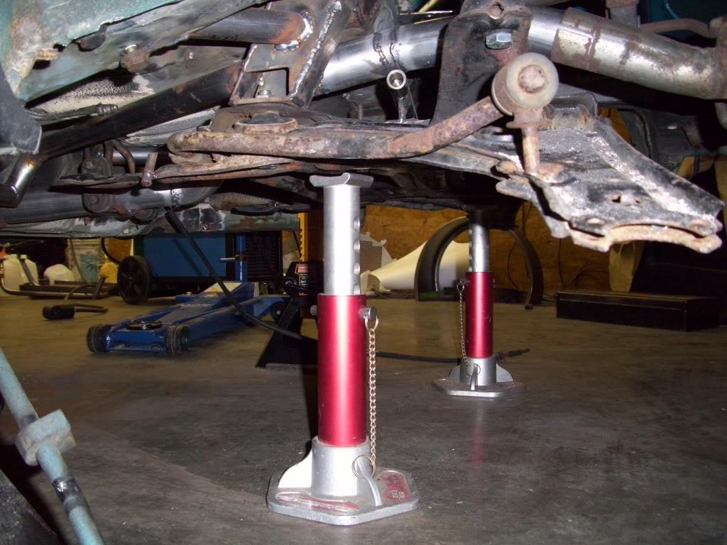
June 17, 2009
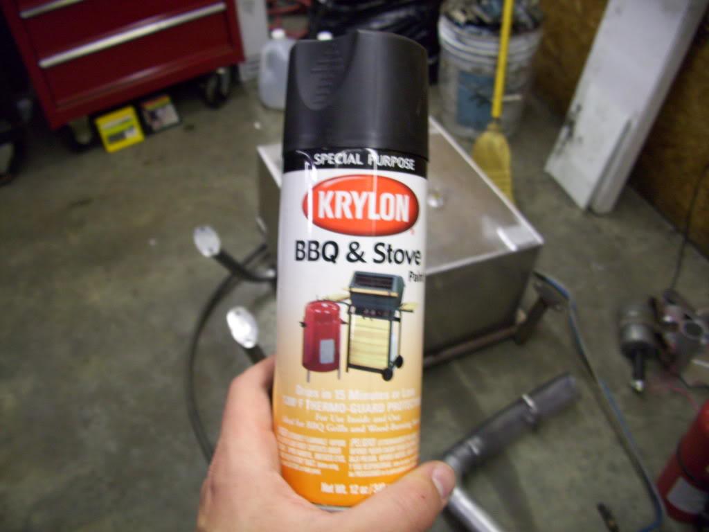
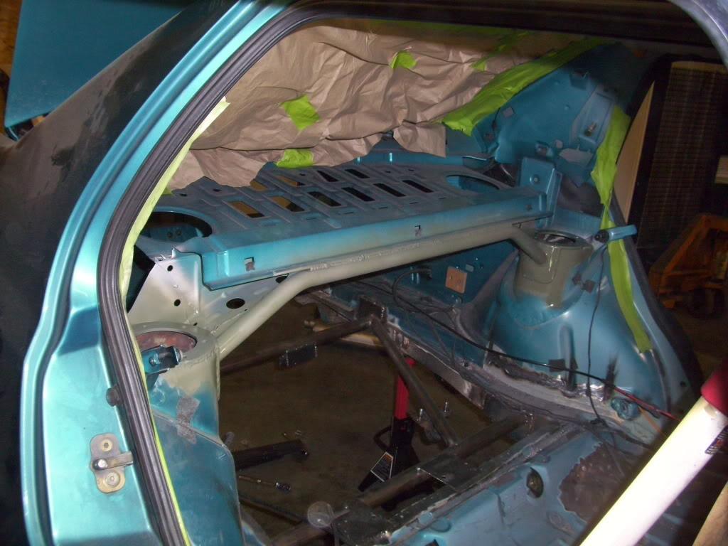
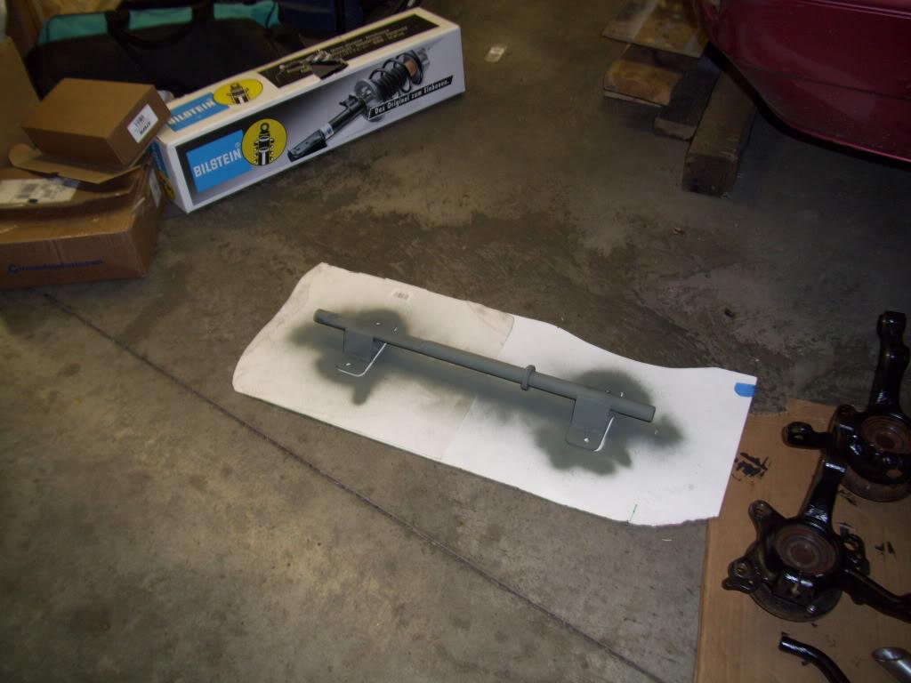
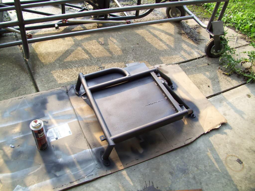
I painted the exhaust and strut tower brace.
June 18, 2009
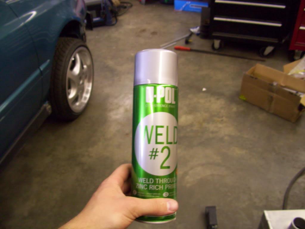
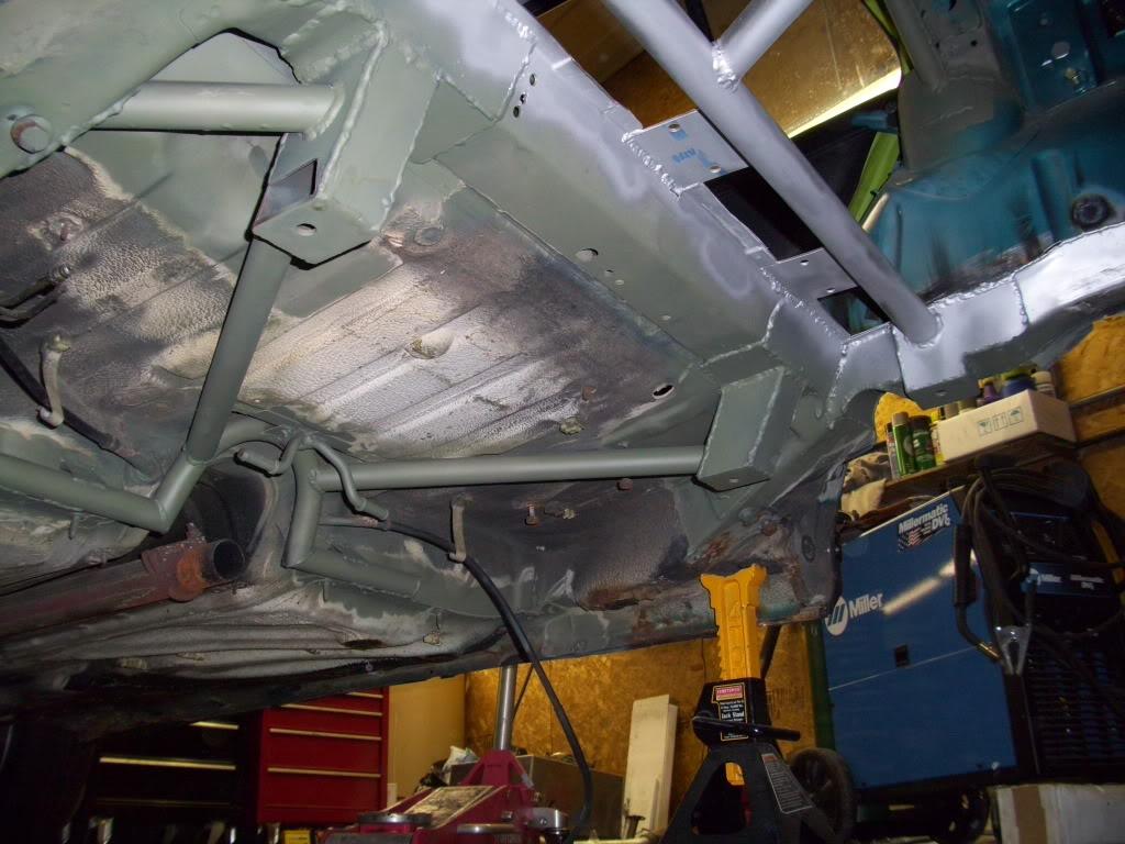
I got the floor in primer. The silver is UPOL Weld-through primer, the green is an etching primer. I selectively sprayed it depending on which areas would need to be welded over afterwards. I spent all night cleaning welds and finishing areas I forgot to weld, the paint was only the last 5 minutes!
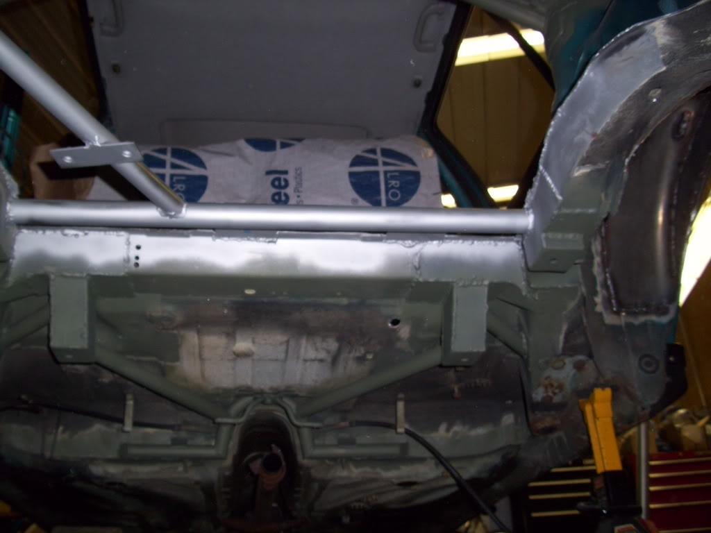
June 20, 2009
I started making templates and did the first cuts for the new sheetmetal trunk floor. These pictures are horrible, I took them myself and can hardly tell what they're trying to portray. It will be more clear later.
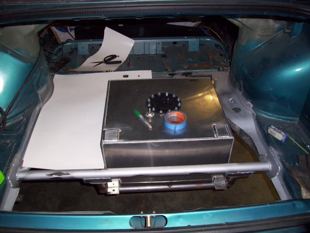
This one is looking from the front drivers seat back toward the passenger rear taillight.
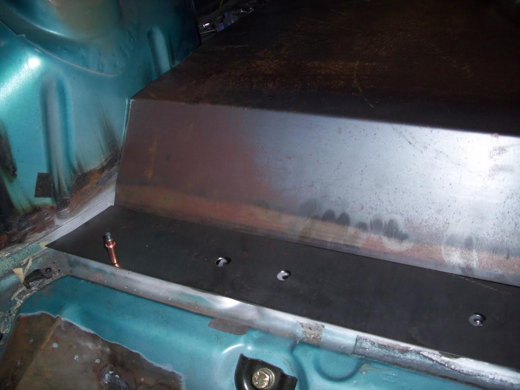
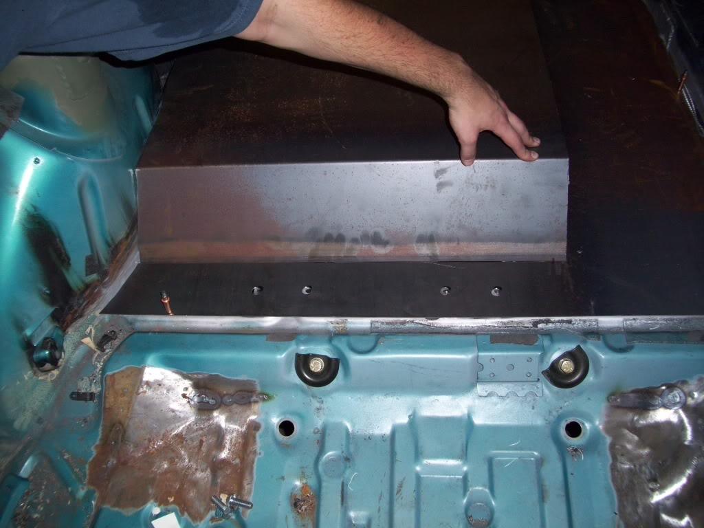
Here is where the flat section meets up with the new rear bumper crossmember
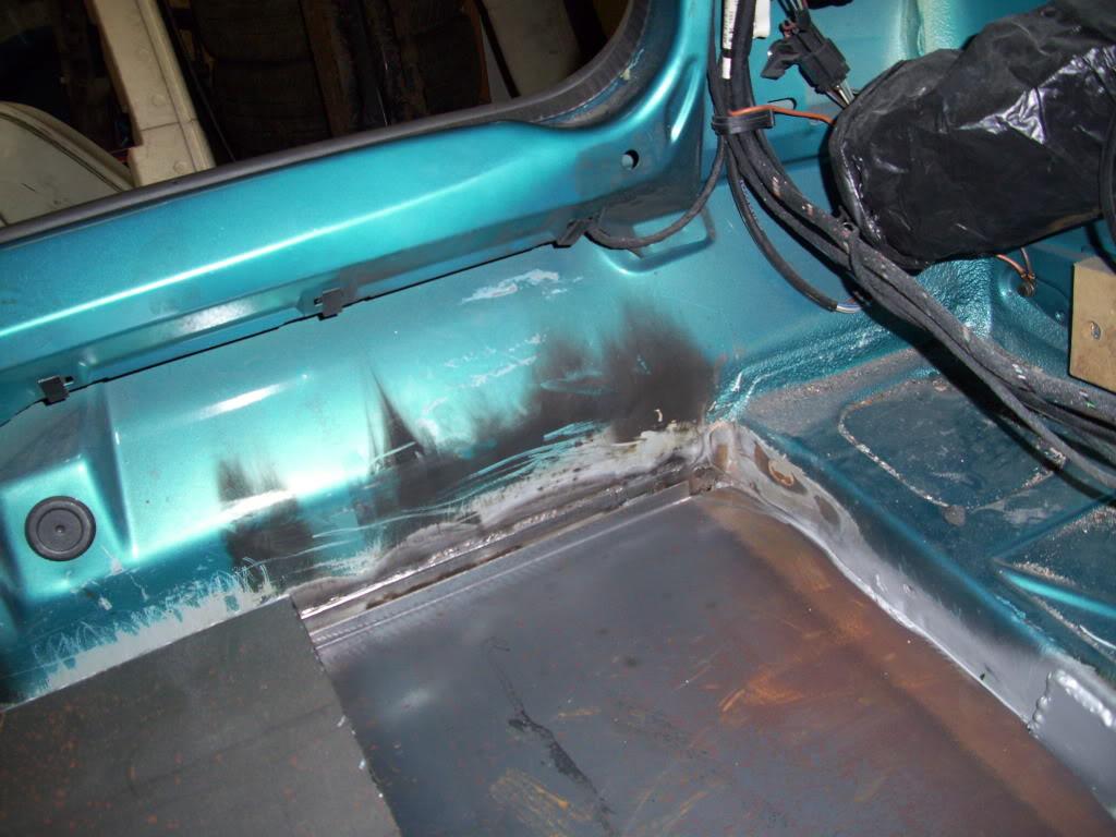
June 25, 2009
Trunk floor is starting to take shape! More sheet metal and primer
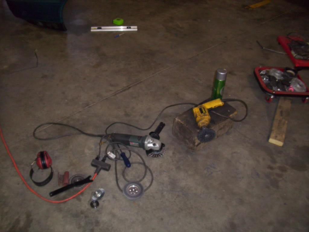
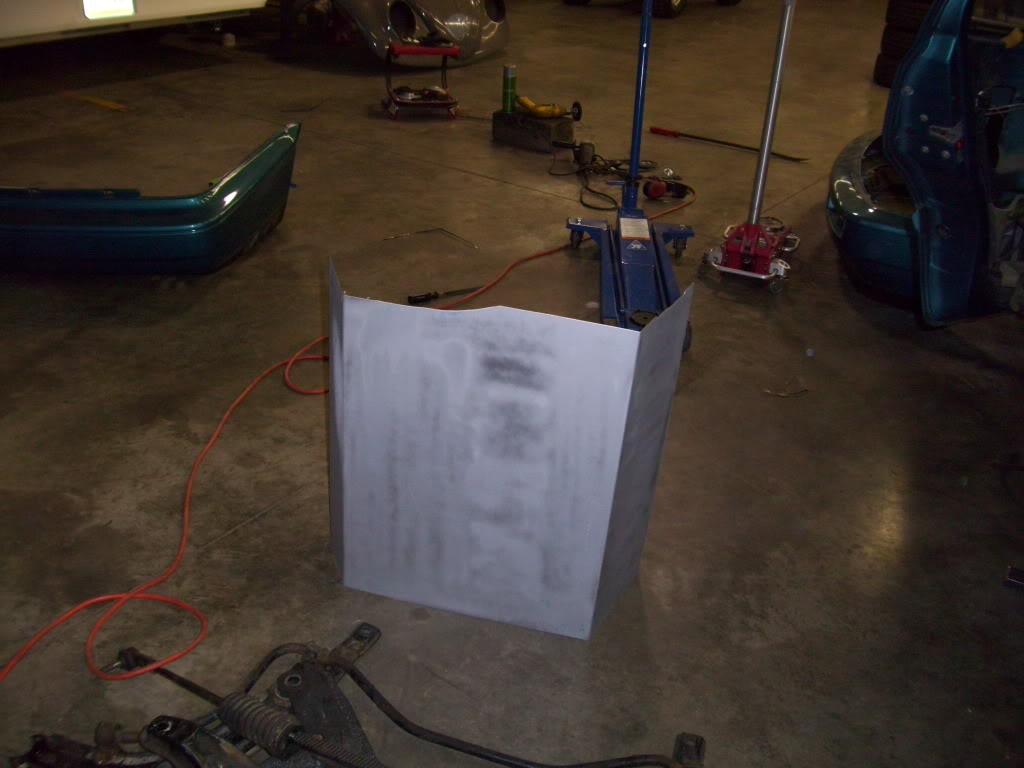

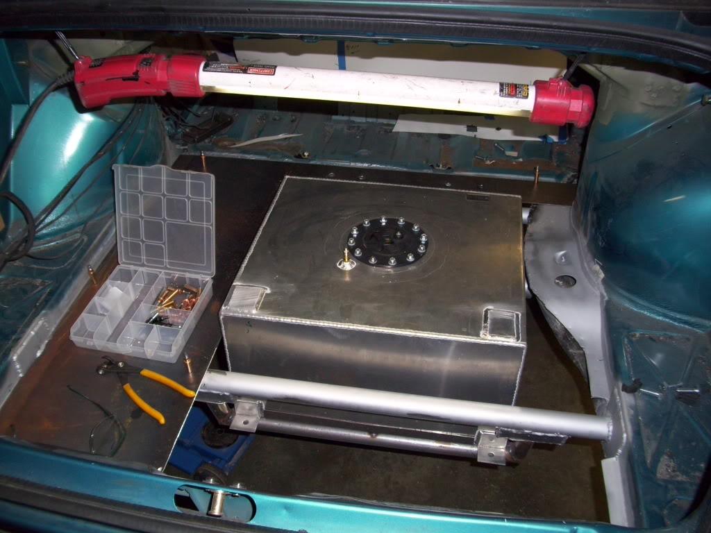
June 26, 2009
I made the tray where the hydraulic pump and valve assemblies will mount. This is behind the fuel cell, just in front of the rear bumper.
The plasma cutter really helped out when making these long cuts
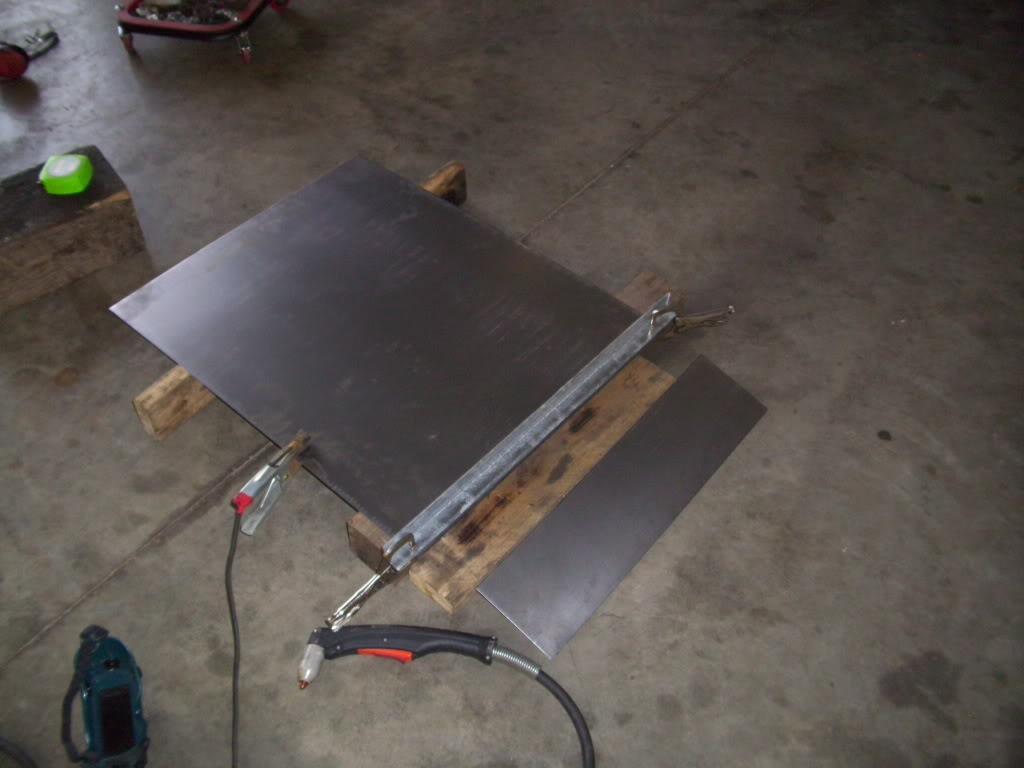
Here's the brake I have been using. It's not mine, but it's badass! I think it's 6' long so if I ever want to build a mk3 limo or something I can.
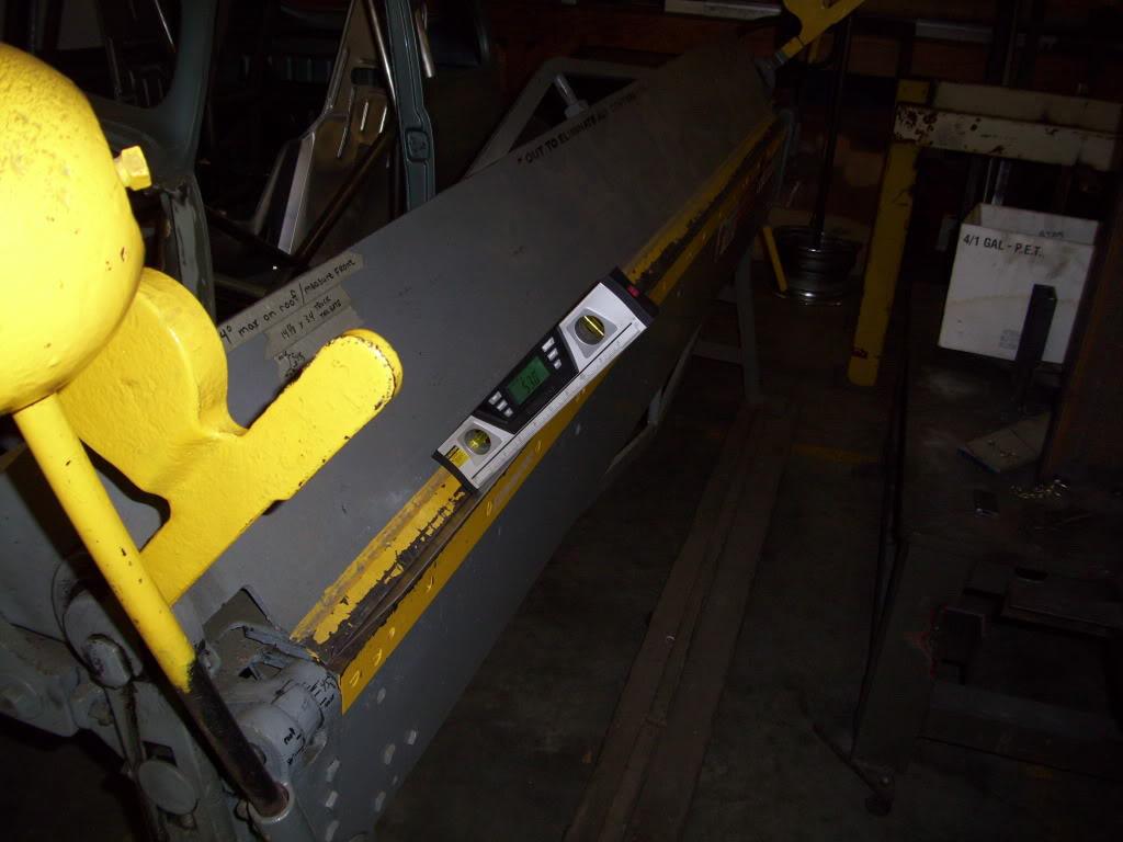
The digital angle finder is helping out. This is also what I use to measure camber when doing alignments, in case I forget to mention that later.
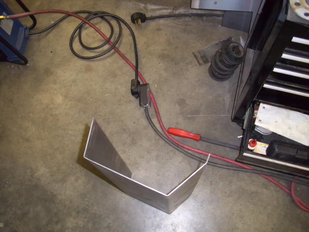
I was happy with all the bends.
In position
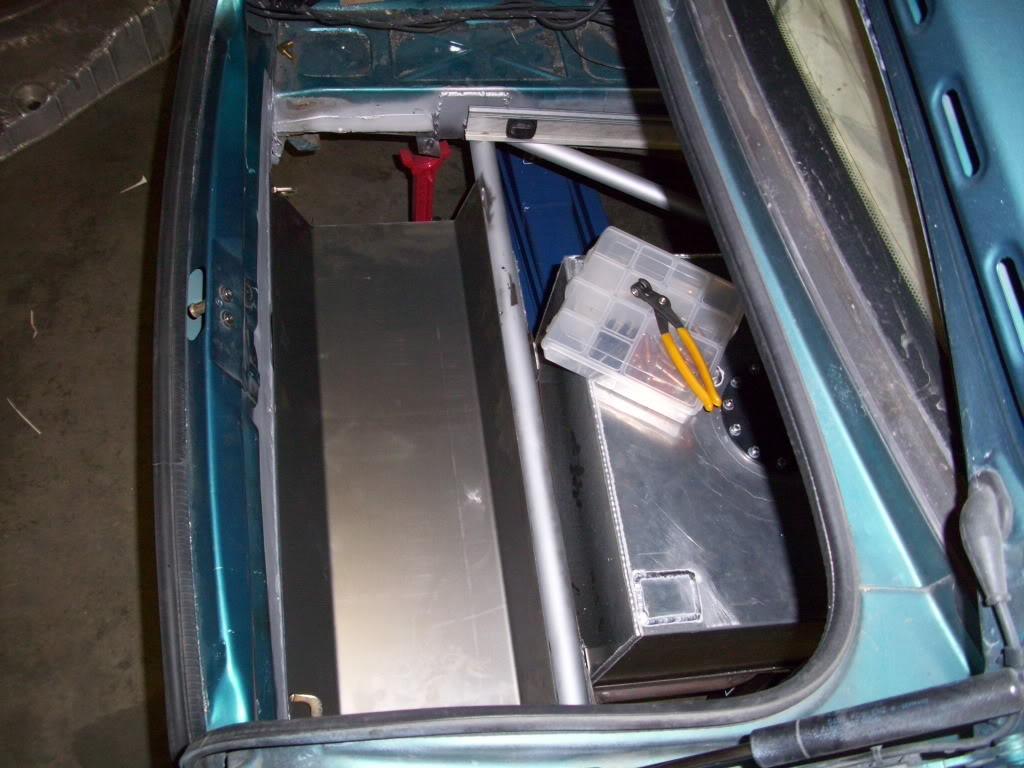
It will be welded to the rear bumper crossmember, this is looking toward the rear of the car
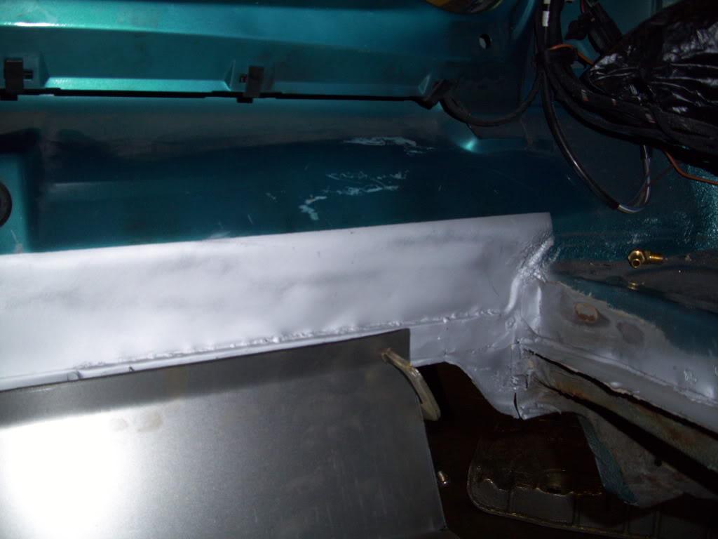
June 30, 2009
I decided to add a bunch of threaded holes in the trunk floor, just for future use to mount things down. That way I will never have to drill through the trunk to mount stuff, there will already be holes ready to go. I used M6 threaded weld-nuts from Mcmaster, drillled a bunch of holes on predetermined spacing, and welded them down to the bottom side of the panels.
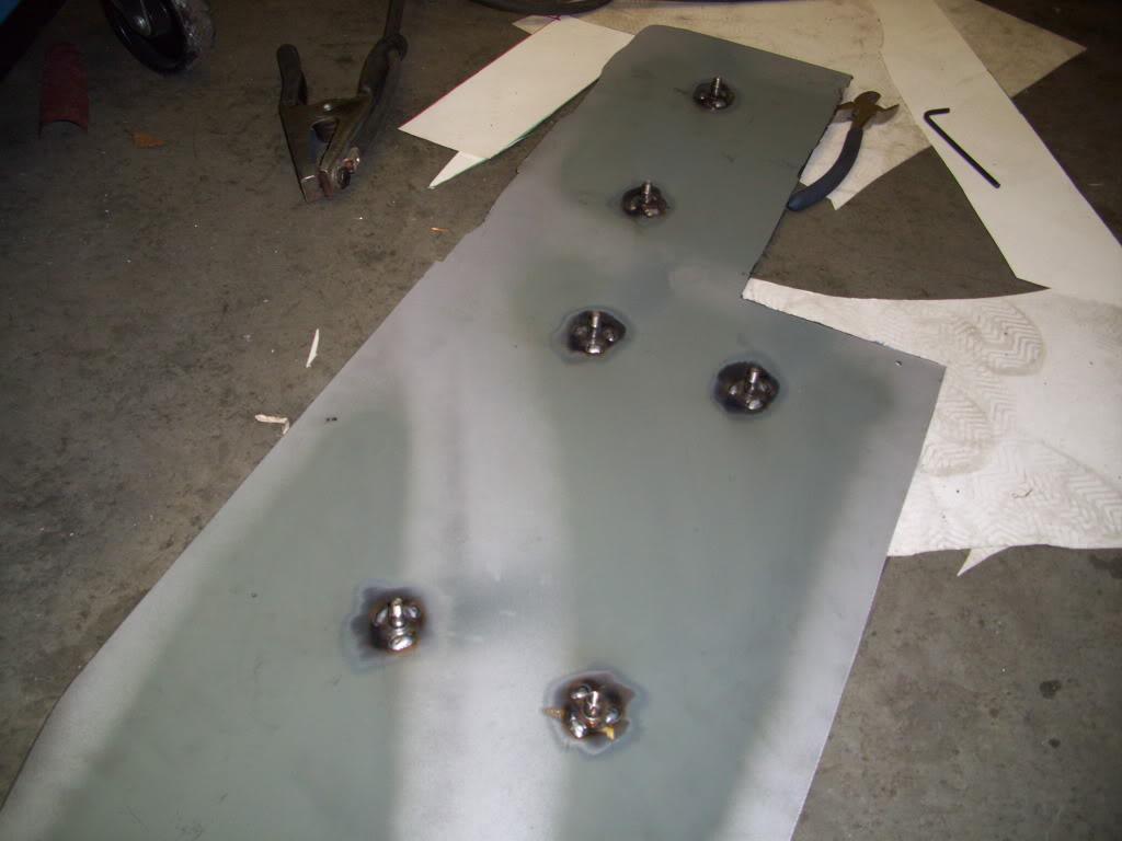
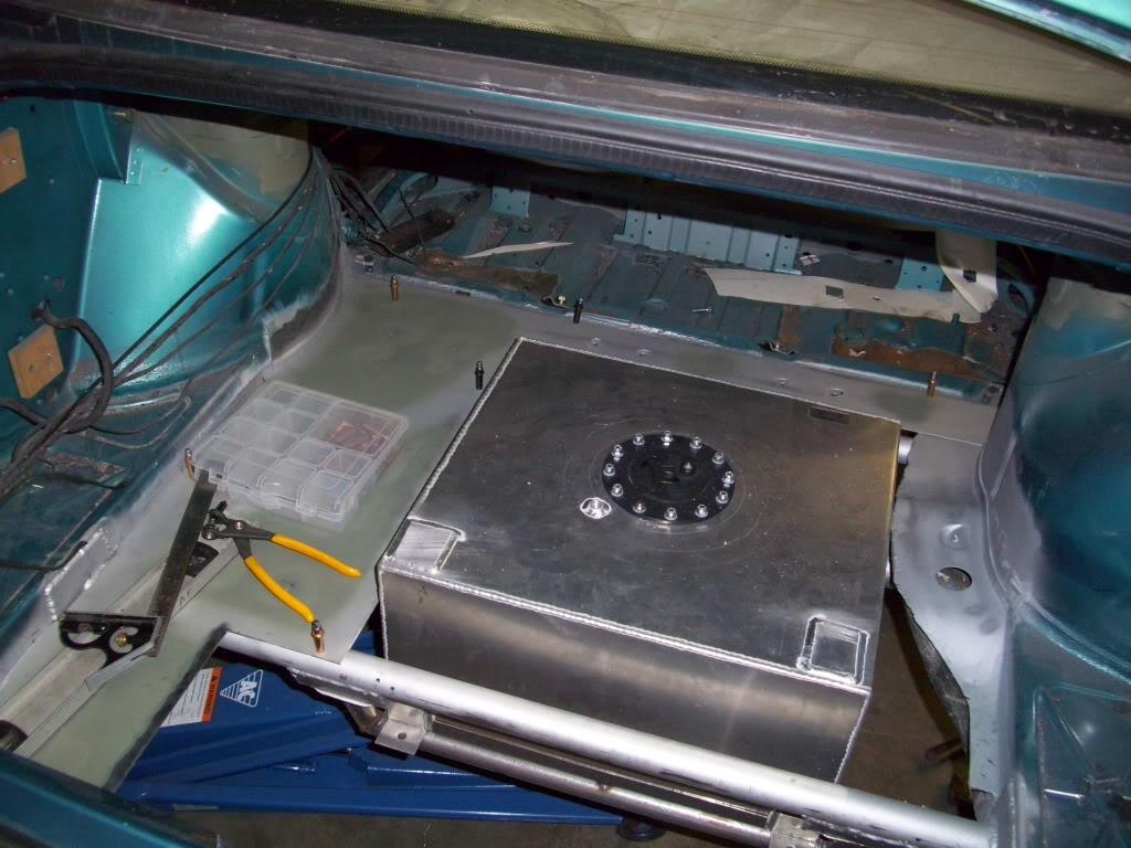
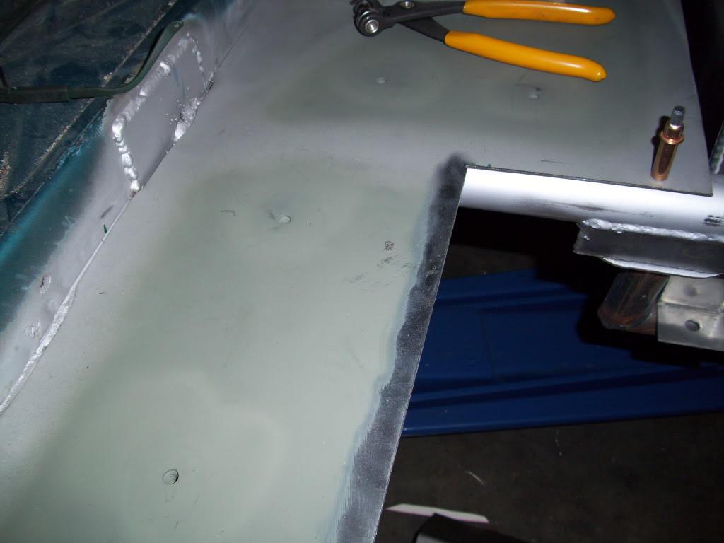
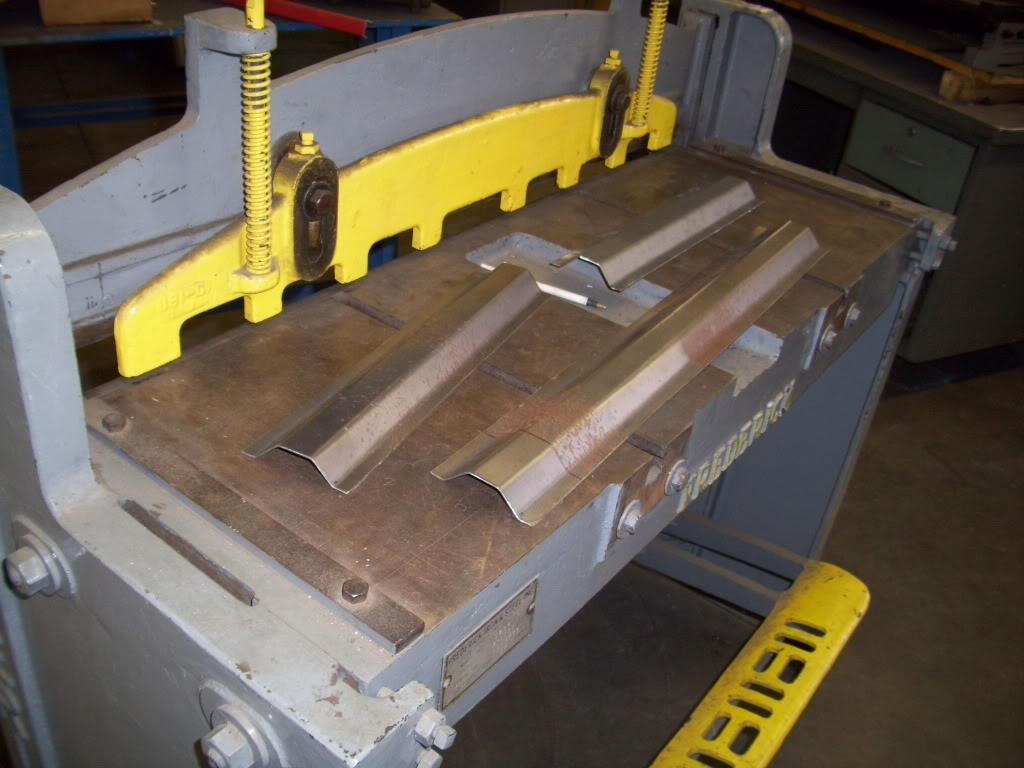
I also did a test bend on the stiffening ribs I'm planning to reinforce the parts of the floor where I can't or didn't add tubular supports underneath.
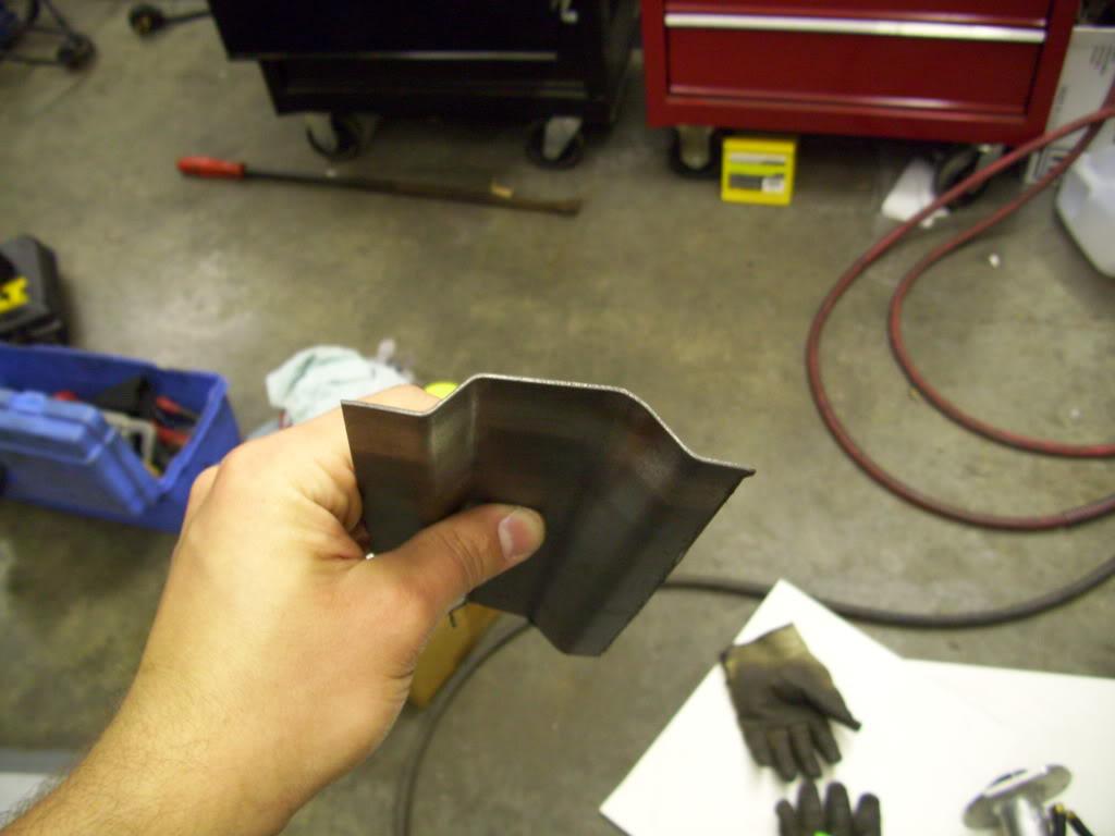
July 1, 2009
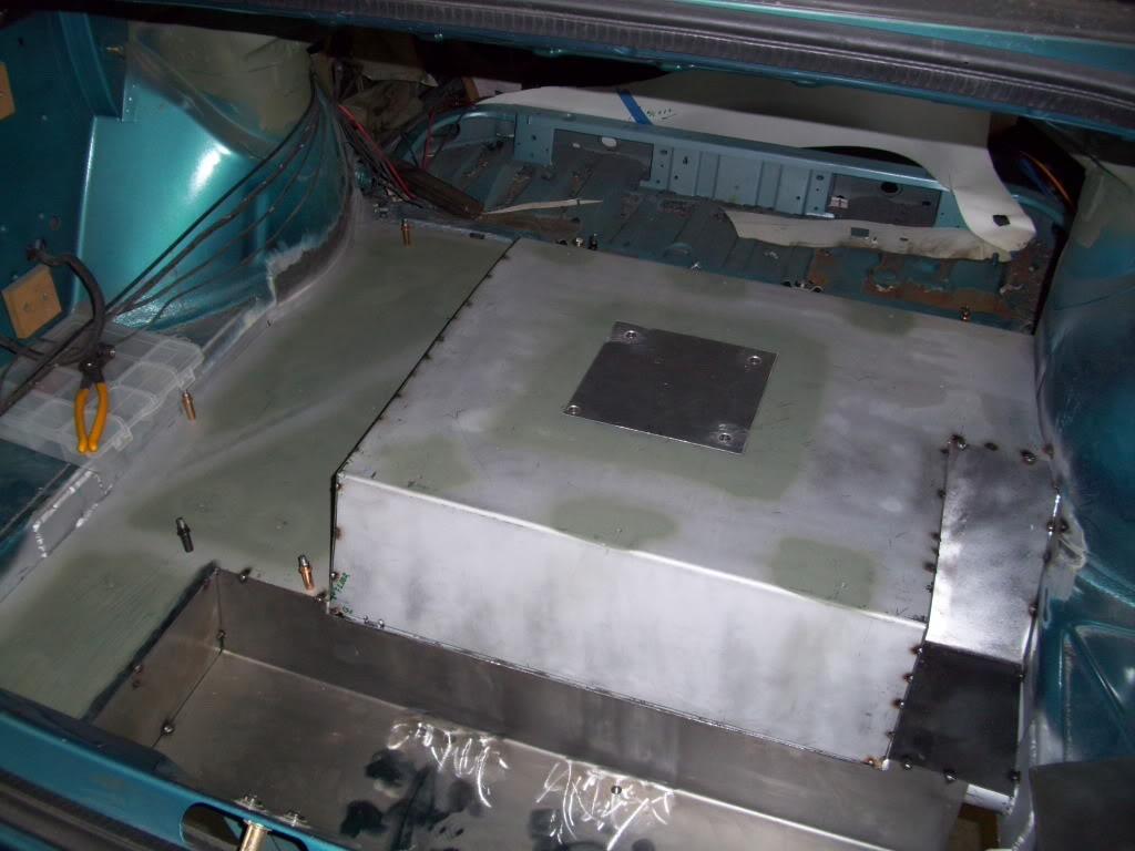
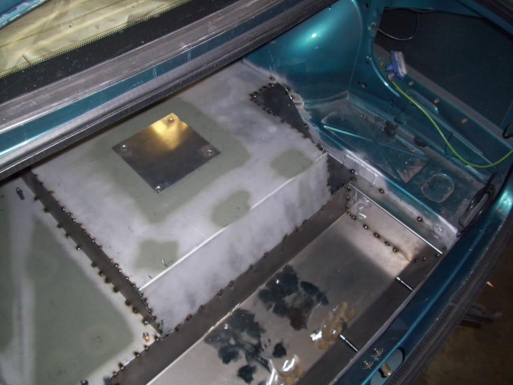
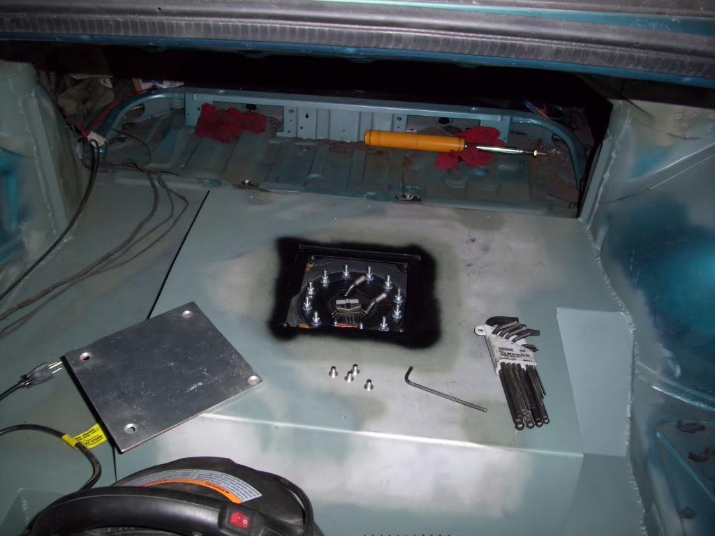
I started making the access panel for the fuel pump. Since the cell is below the floor, I dont' want to have to drop the tank to change or modify or unplug the fuel pump. Despite how easy it will be to drop the tank, if I don't have to I don't want to.
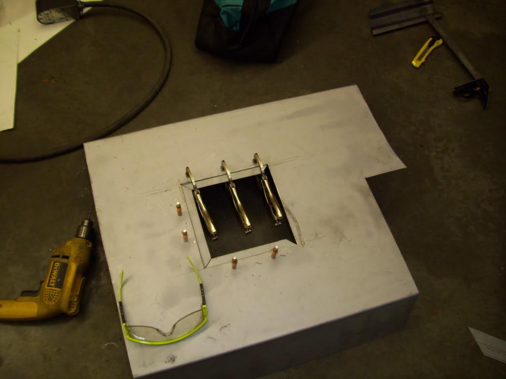
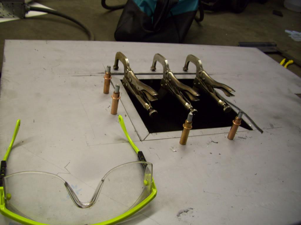
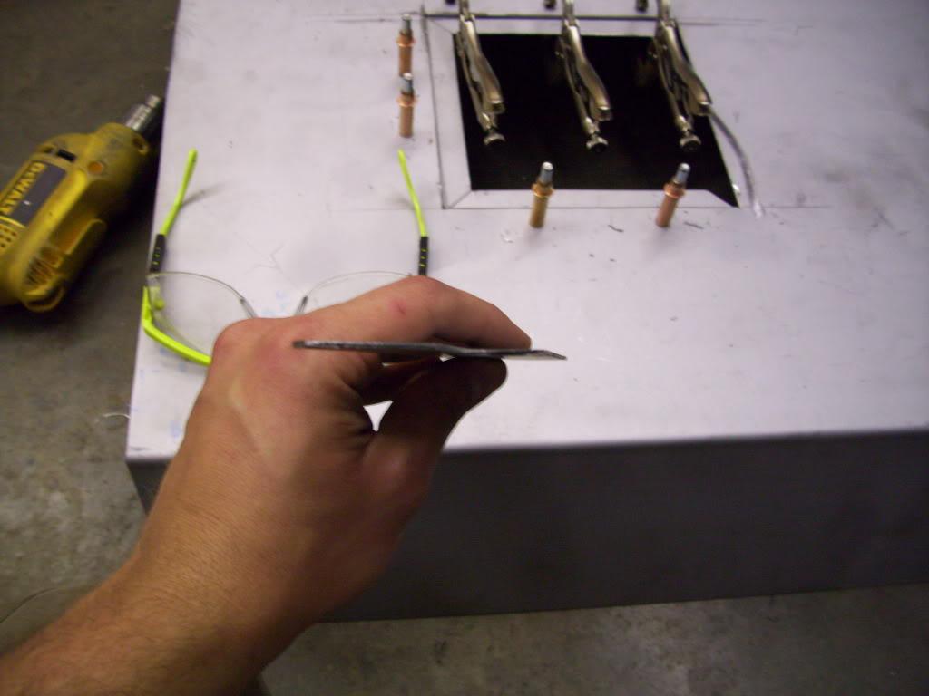
Those are Cleco clamps, for those who have never seen them. You drill a 1/8" hole and insert them through, and they're a temporary holding system.
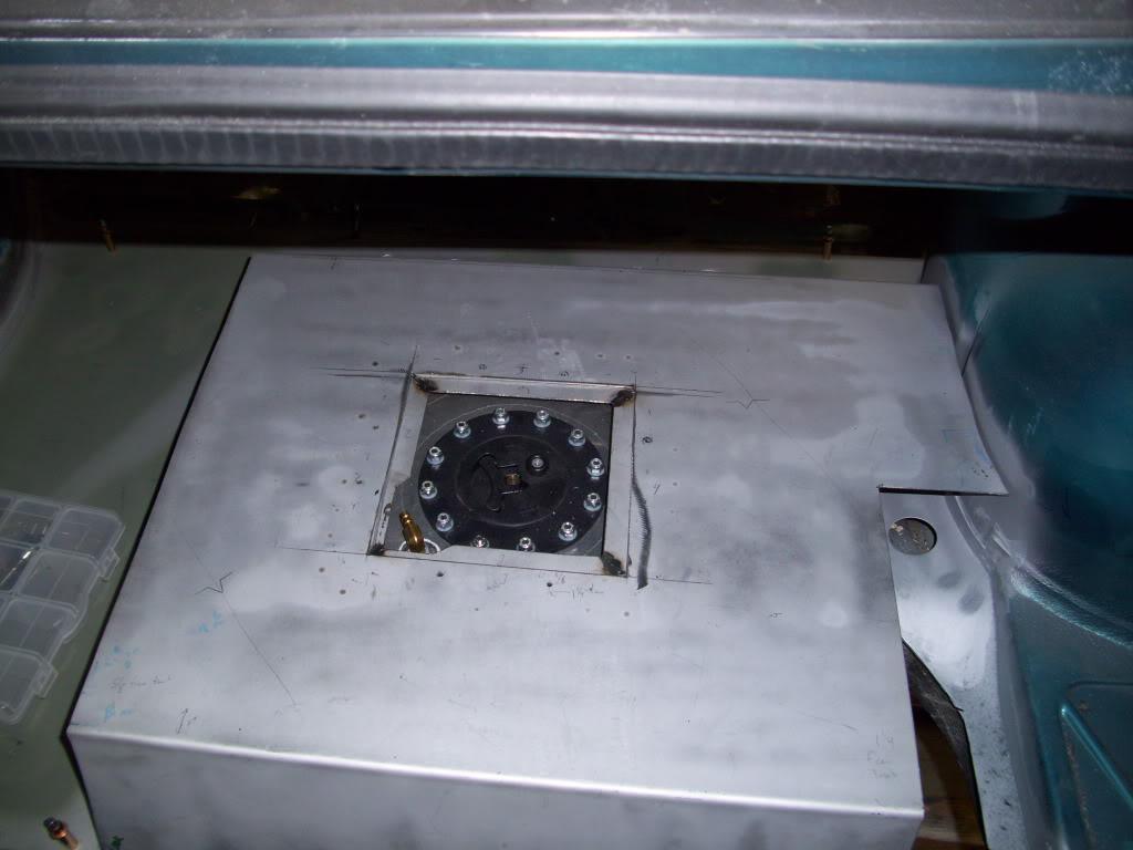
Aligns perfectly with the fuel cell access port
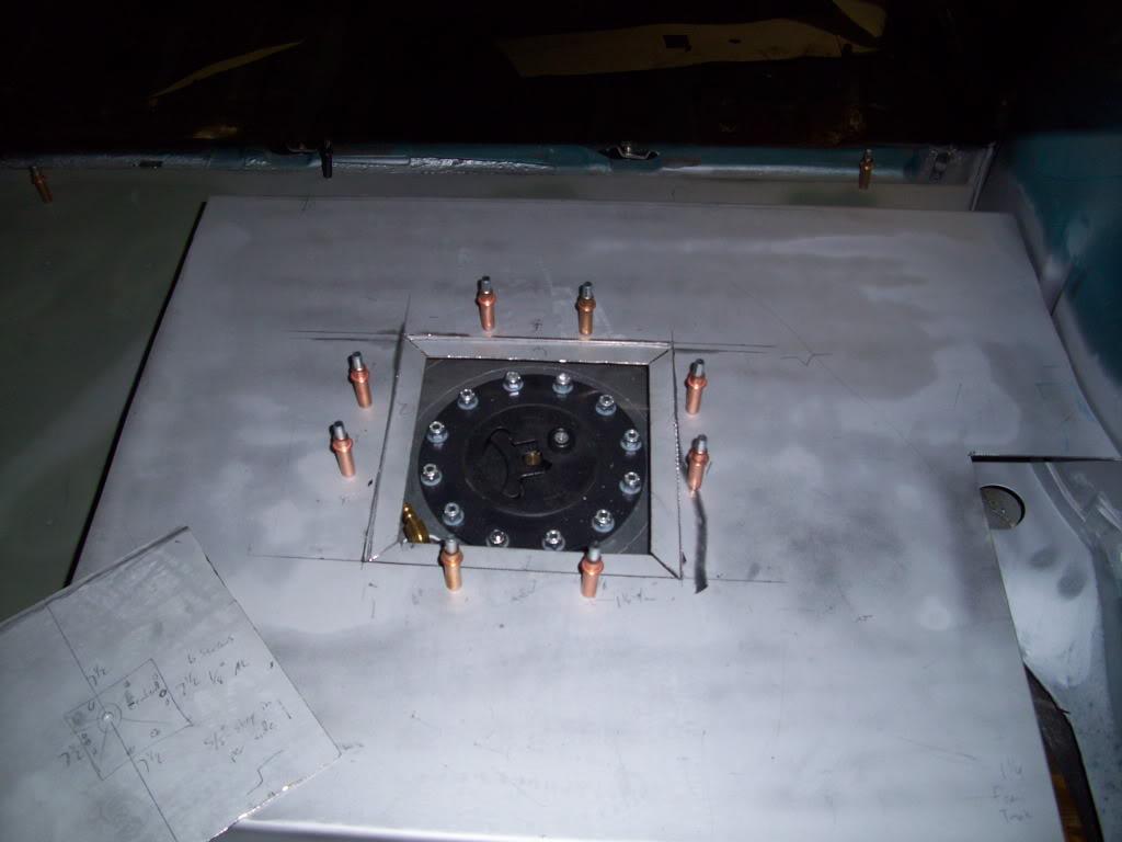
Tack welded it all together and removed the Clecos
June 2, 2009
I welded up the mounts, very slowly to avoid warping in the large flat panel. It ended up warping just slightly, but I couldn't avoid it.
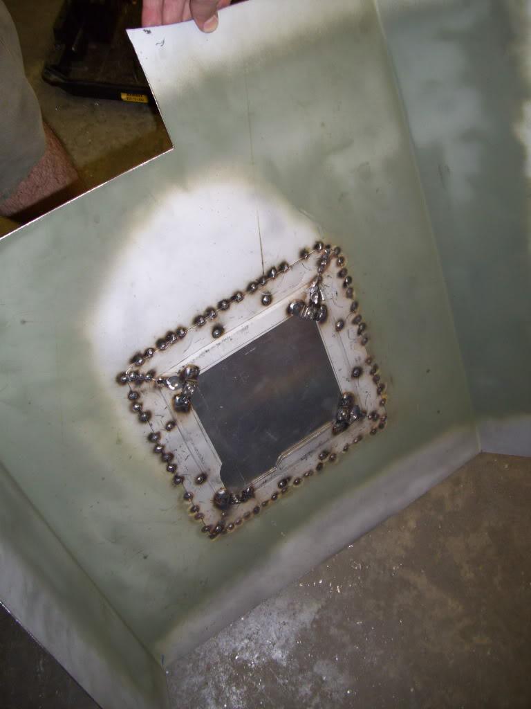
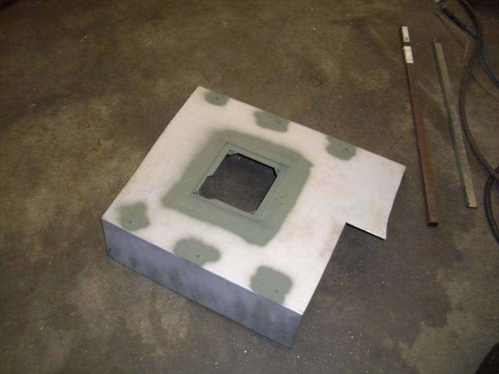
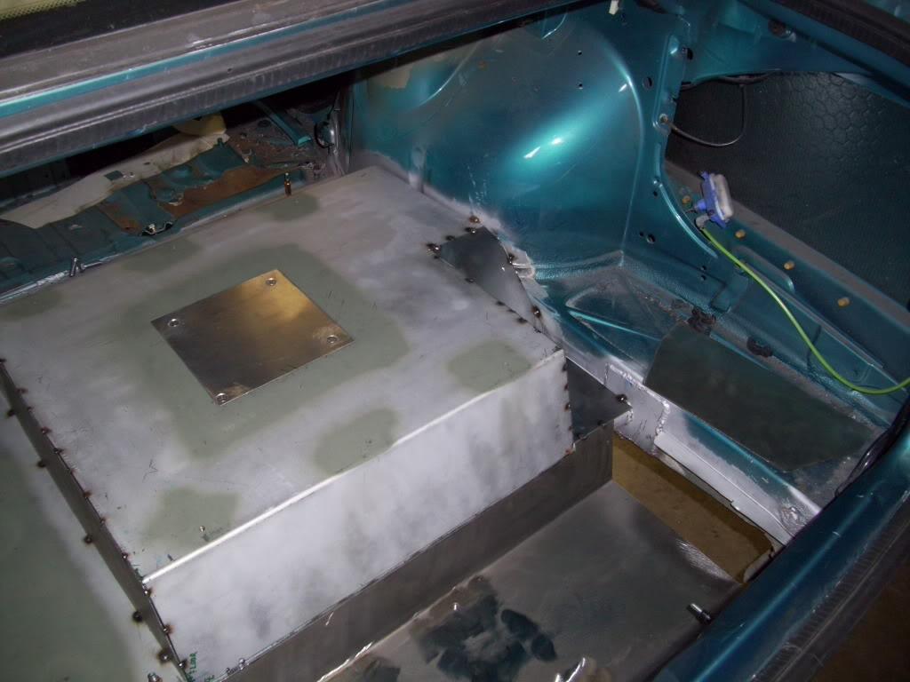
Then I made this coverplate from 1/8" aluminum and flat-head M6 screws. I needed it to be completely flush so that I can easily integrate it into a flat false floor later.
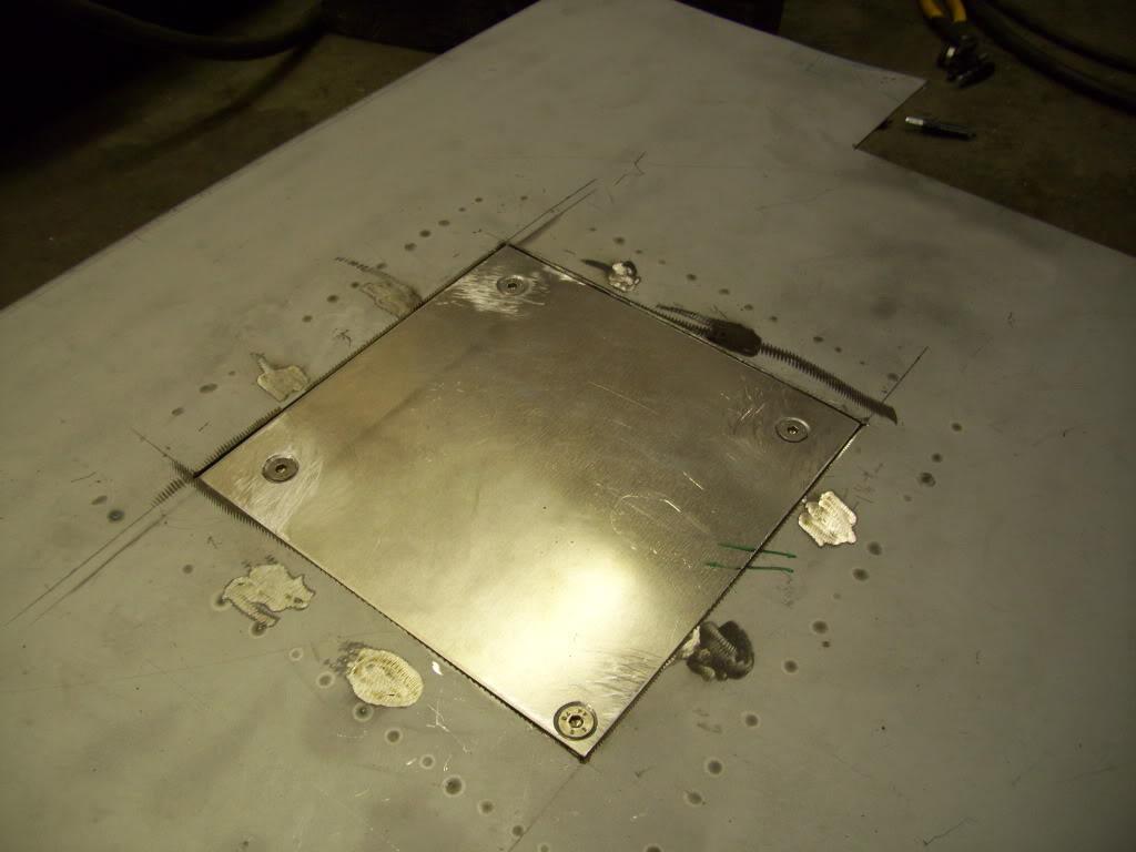
That 4th hole is supposed to be in a weird location. If you look at the shape of the opening, I made some clearance cuts for the vent tubing in that corner and had to move the 4th hole really close to the edge. That was planned, and unavoidable unless I made the square cut larger, which I didn't want to do.
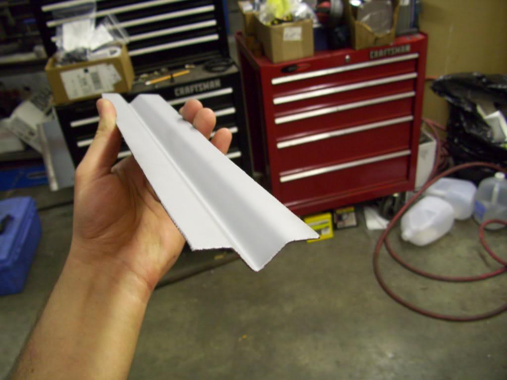
I also made a few more stiffening ribs, these will get welded to the bottom side of the big flat section later to keep it from vibrating and stiffen it up so I can pile heavy crap in the trunk if necessary. Like dead hookers. My last name is Italian...
June 4, 2009
I think these pictures are actually from both the 3rd and 4th, but whatever.
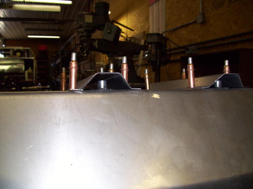
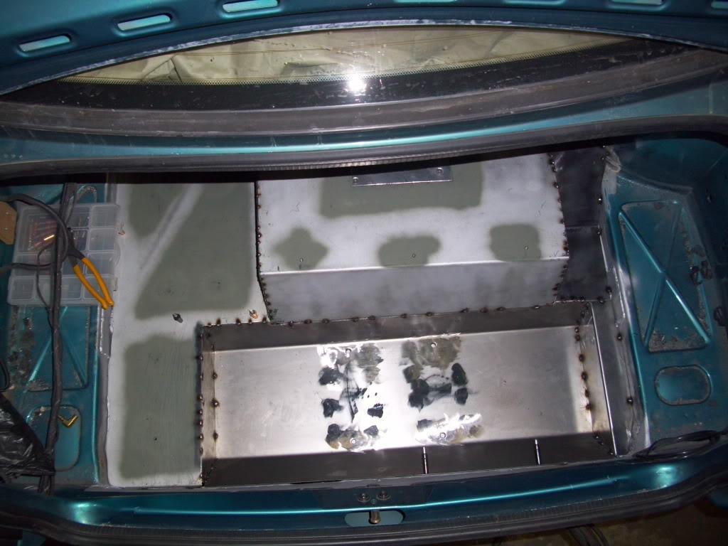
Trunk floor is almost done! Lots of little sheetmetal work. I also started making ribs underneath the hydraulic pump mounts, so I could just bolt the pump directly to the floor. It appears unreinforced, but there is heavy bracing on the bottom side. Hidden and clean is how I prefer!
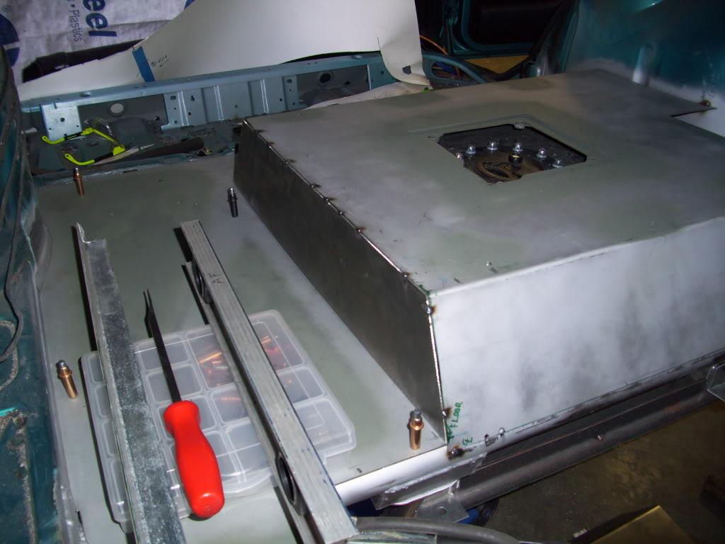
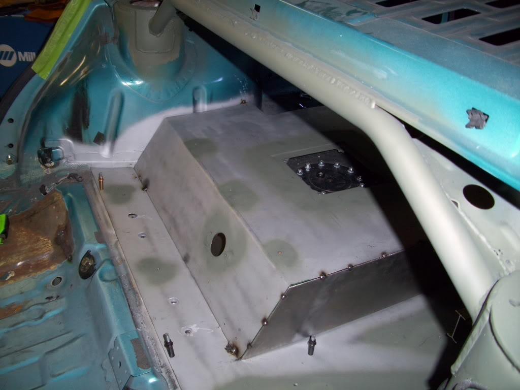
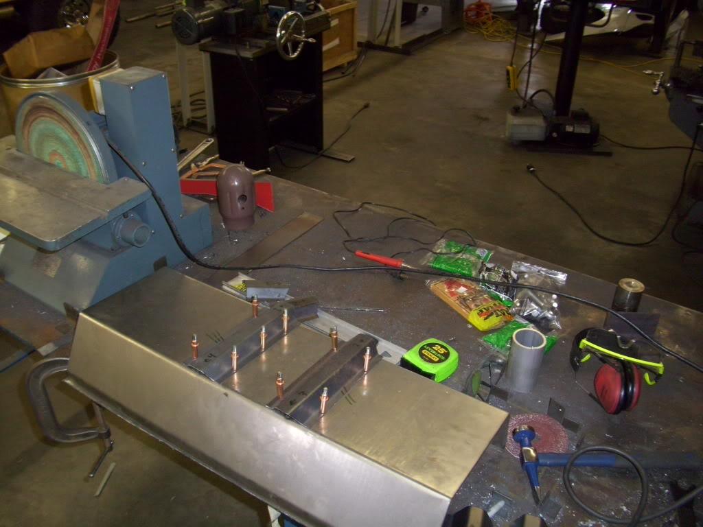
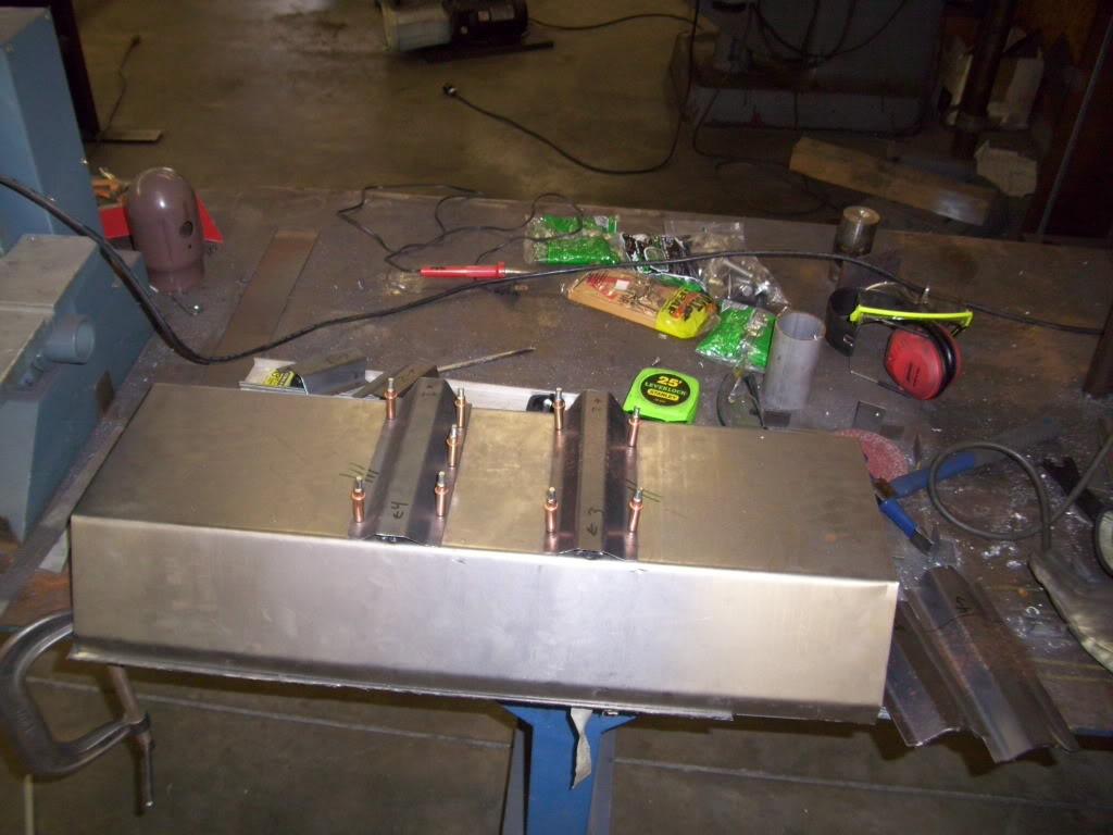
More welded inserts built into the floor where the hydraulic pump will mount
June 6, 2009
I got the floor just about finished up. You can see how the ribs extend under the pump and directly into two crossmembers, giving plenty of strength to the area where the hydraulic pump will mount. It's a heavy bastard!
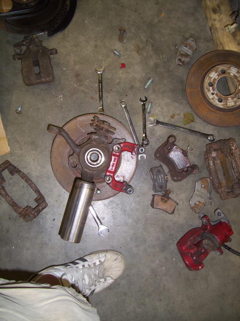
All my research led me to the mk4 GLI/337/20th rear brake calipers. They were designed for a 22mm thick vented rotor (stock mk3 front is 20mm) and can handle a 10.1" rotor. I took a gamble and ordered a used set from Unedrgorundvwprts. I intentionally misspelled that so they don't seach and Ethug because I'm going to talk some trash. These came in horrible condition, they were useable only because I wasn't using all the parts that came in the "100% complete" kit. I can't be too upset though because the price was right, so whatever. I ordered a caliper rebuild kit just in case, and the boots were all torn and bolts were all stripped but nothing I couldn't deal with. The paint was terrible too, but whatever I'm repainting them black anyway.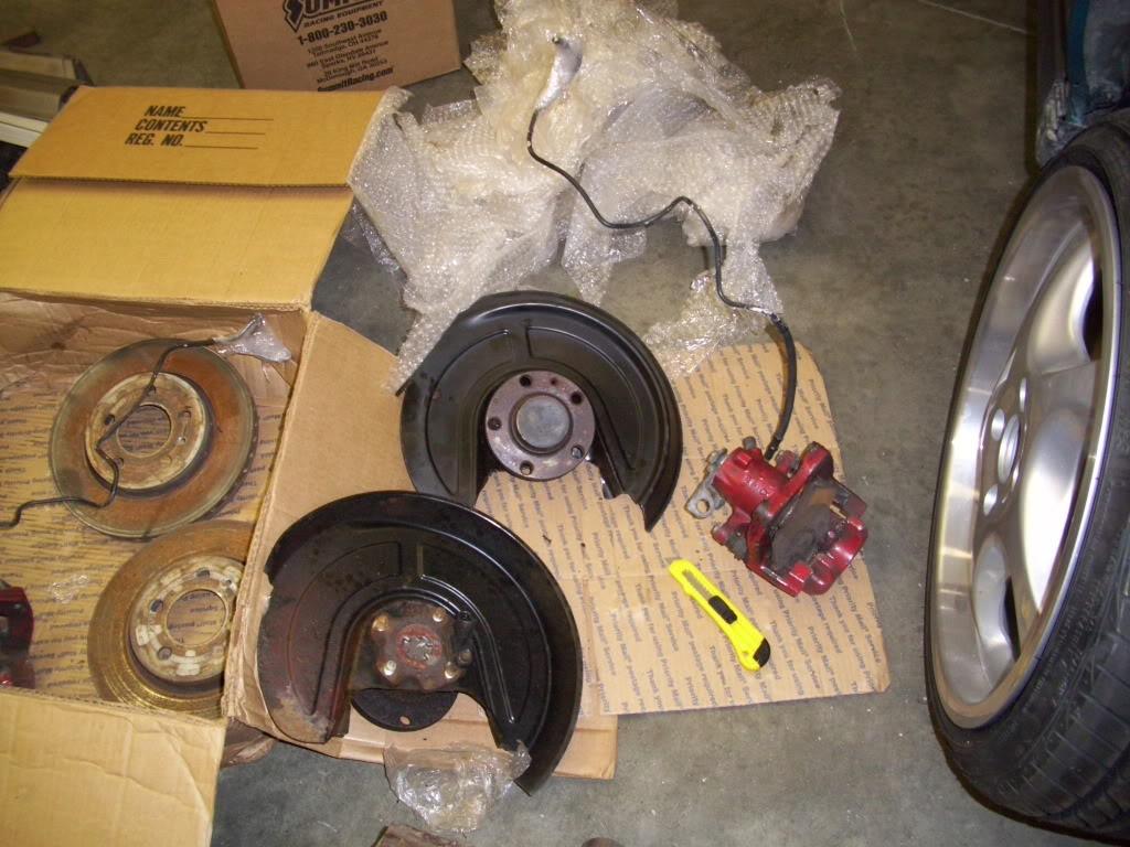
The current and final plan: MK4 GLI rear calipers, MK3 rear pads (same as mk4), mk3 2.0 front rotors, mk4 GLI rear pad carriers machined and modified to mount to the mk3 2.0 front spindle. Say that 5 times fast!
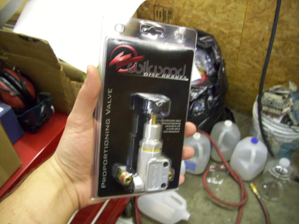
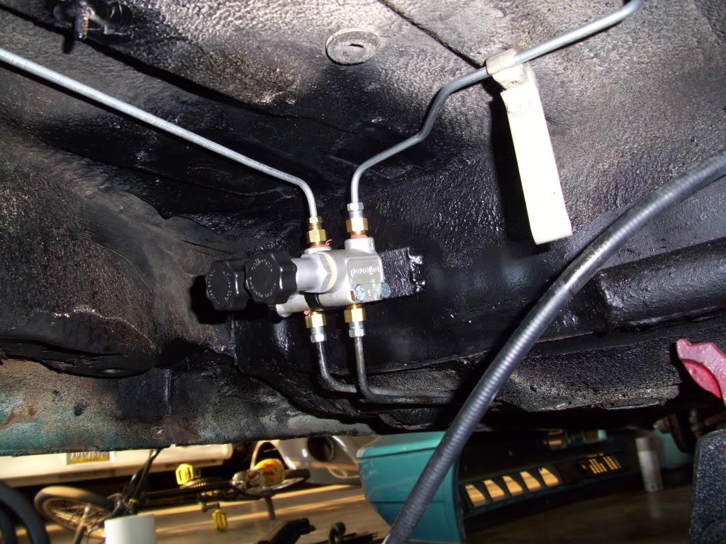
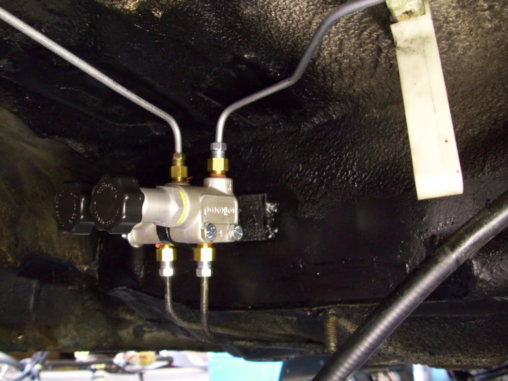
I also received my Wilwood inline proportioning valves, since I deleted the stockers with the whole rear beam. I bought two of these, which will be mounted under the floor on the diagonally split rear braking system.
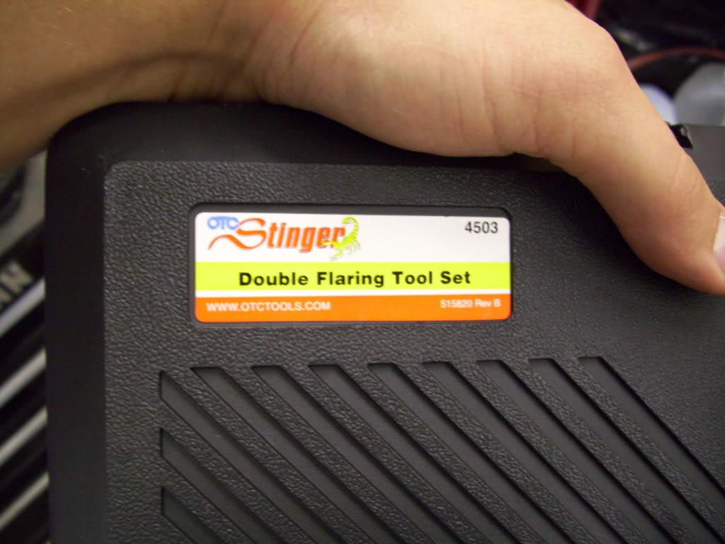
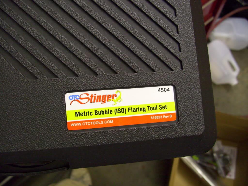
And I got some flaring tools. ISO Bubble for the VW stuff and 45º double flares for the Wilwood stuff.
June 9, 2009
I had planned to make a guard for the fillerneck, in case I would blow a tire or hit a large rock, to minimize the chance of a fuel system break. I got to use the press brake a little, and whipped this guy up from a piece of trailer fender and some sheet.
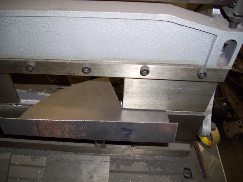
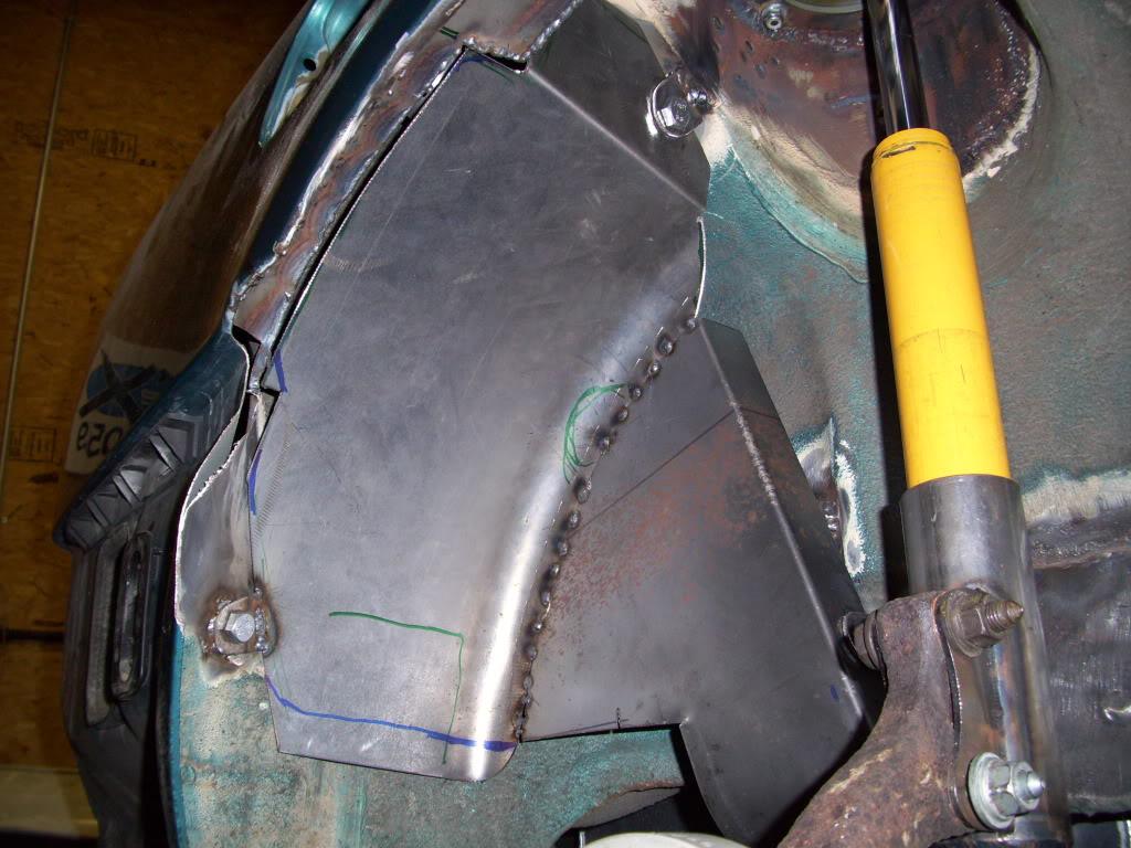
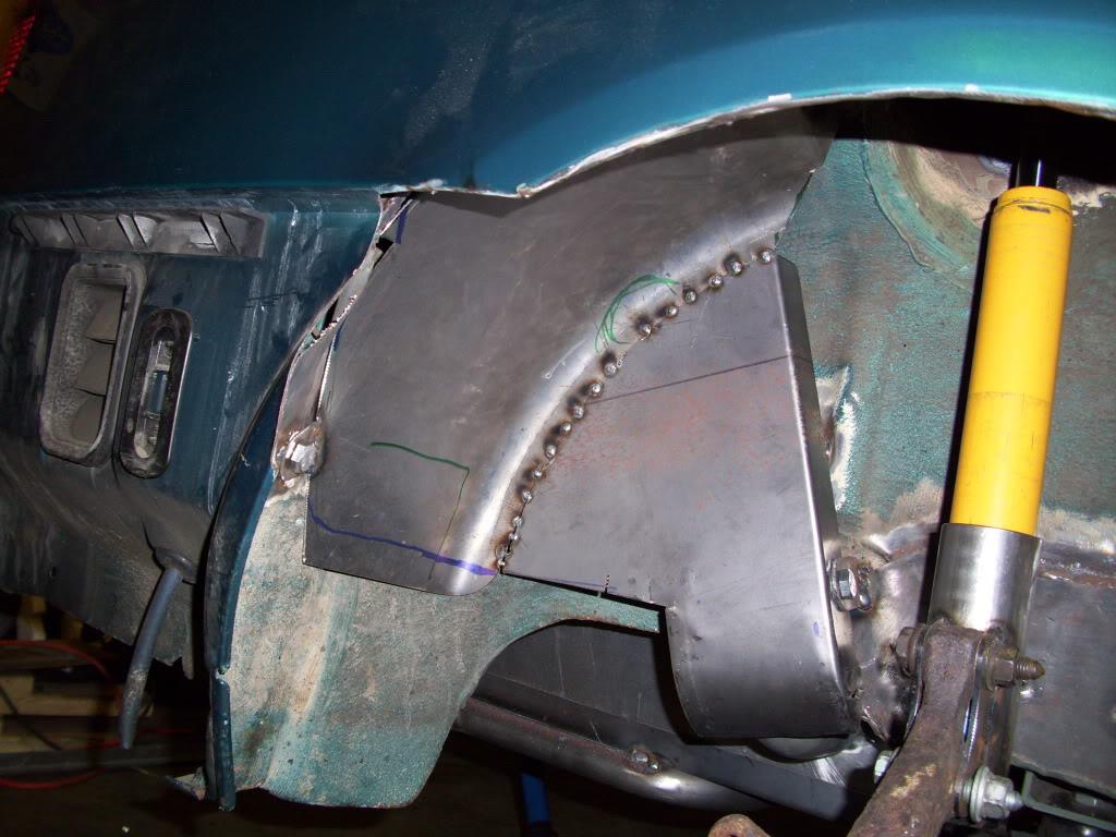
July 11, 2009
I finished up the fillerneck guard, and did a lot of finish welding in the trunk. The whole trunk is all flat sheets, so I couldn't just weld long beads without it warping. I tacked and let cool... tacked and let cool... and repeated that cycle about 500 times!
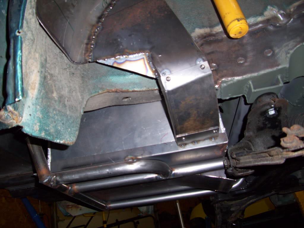
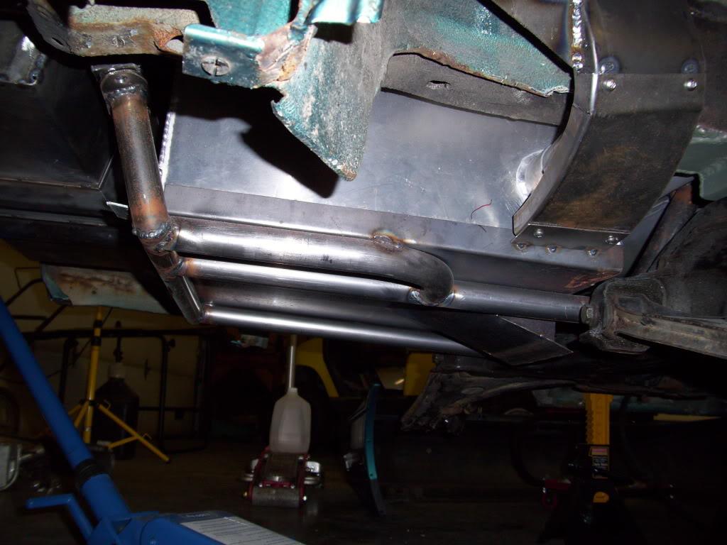
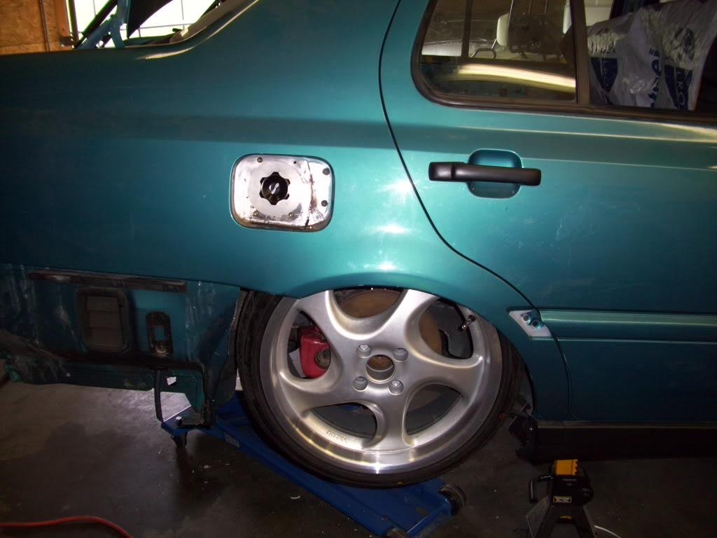
Test-fit the wheel again, plenty of clearance around the neck guard.
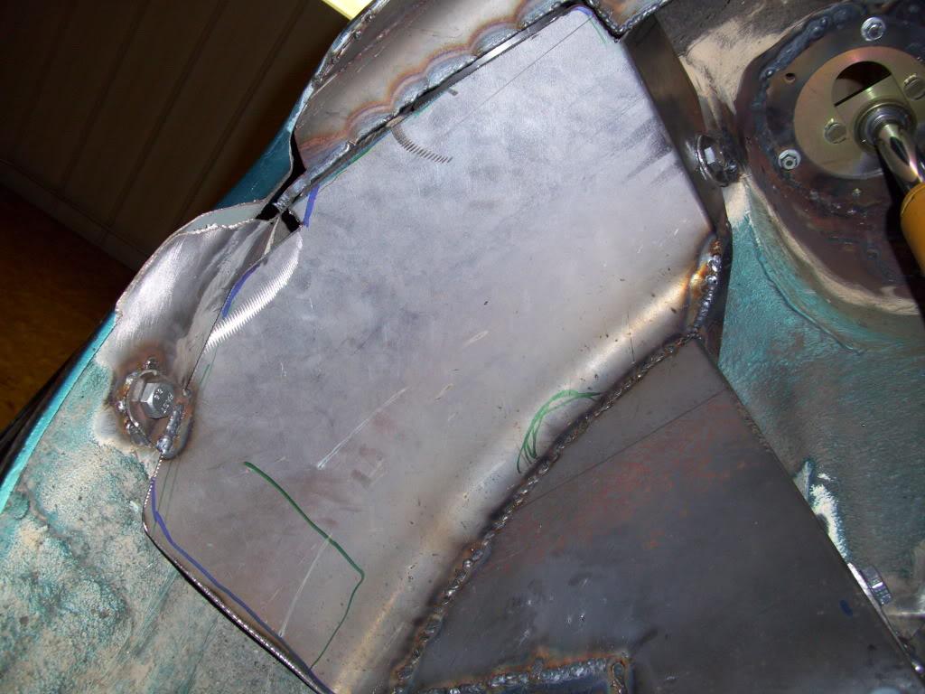
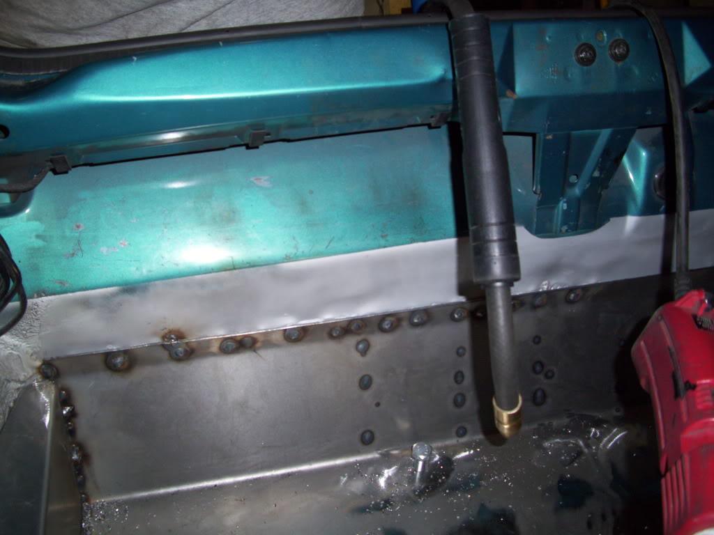
The floor was plug welded through to the underlying tube work to give it more strength. To do this, I would drill through, Cleco clamp them together, then drill another hold right next to the clamp and weld that. Then move the clamps and keep repeating until it was welded in many places. This basically duplicates the factory spot weld type of connection.
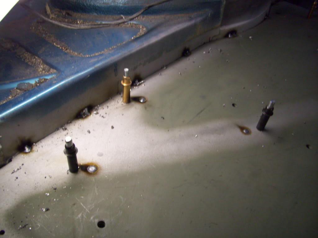
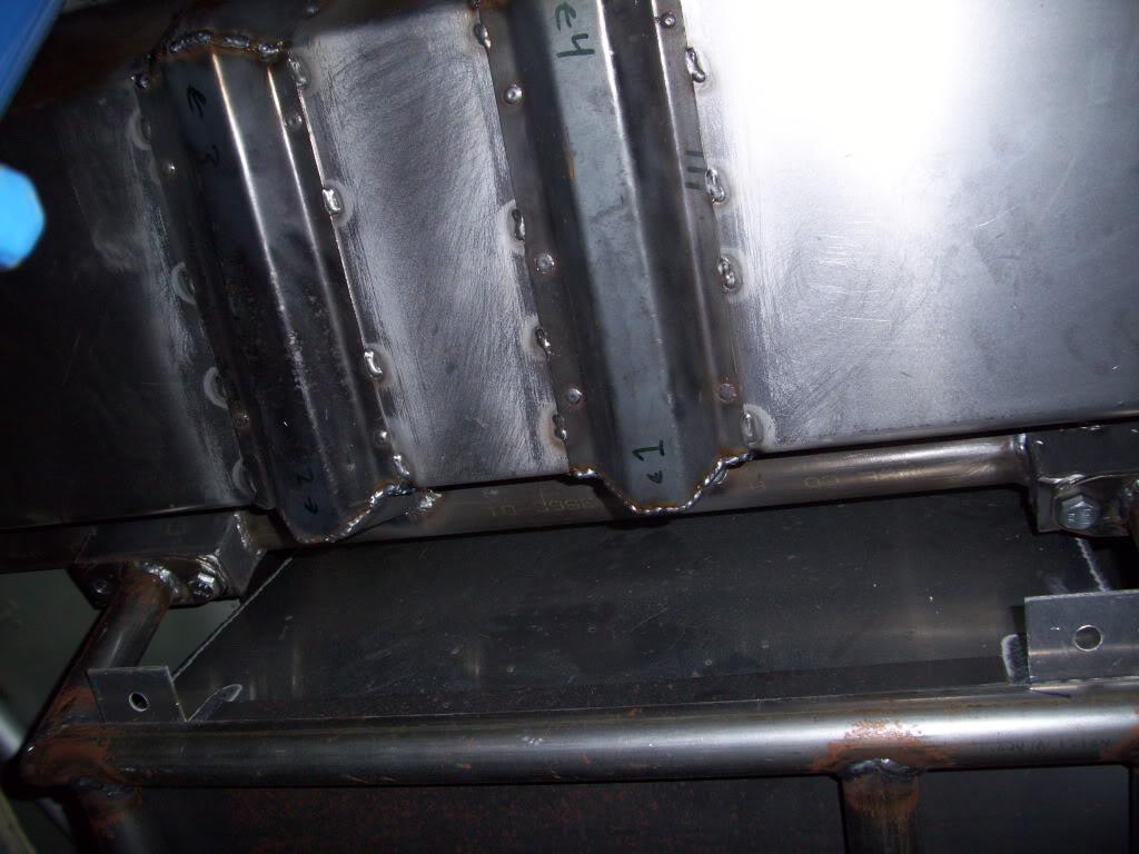
This started to get boring.
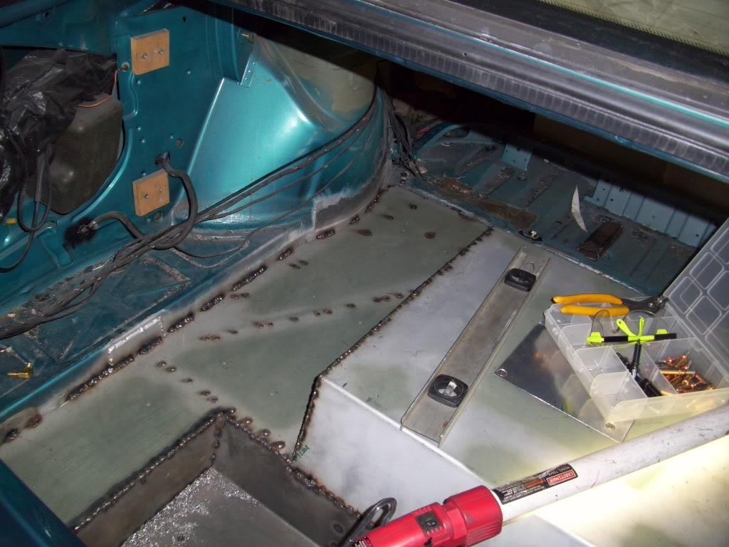
Plug welded back at the rear section. This will not get fully welded because the stock steel is so thin. For those of you who saw the water leak in the trunk at H2O, this is where it's coming from - this joint - which was not completely seam sealed before the show due to time constraints.
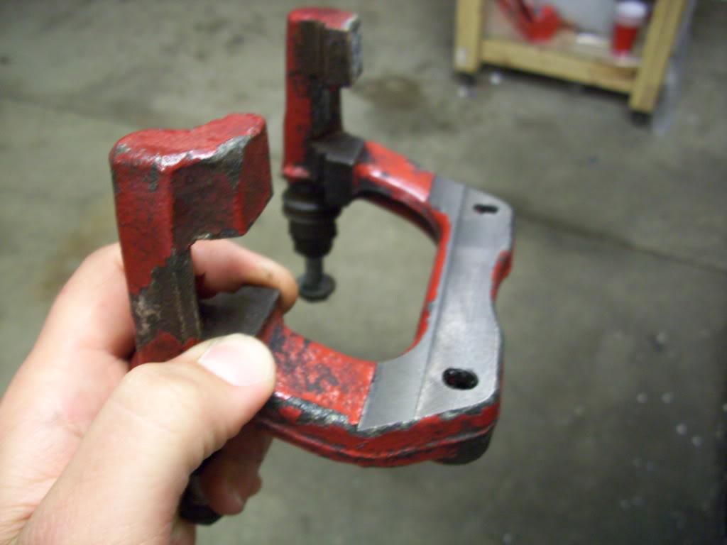
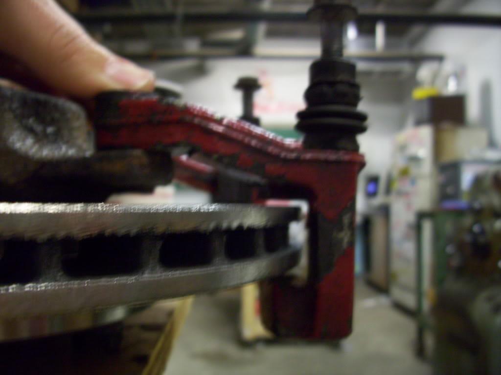
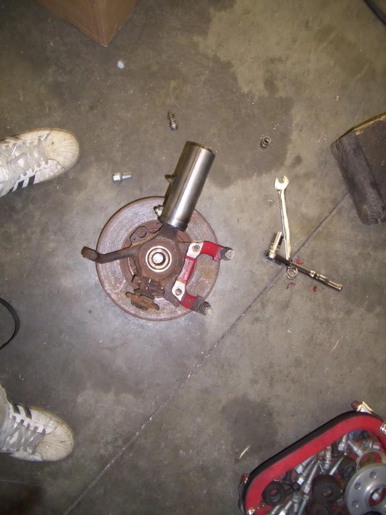
I also did the machining on the stock rear calipers. I'm honestly not too proud of this part, the slotted holes aren't the best idea. On a rear caliper with two high-grade M12 mounting bolts, it will be just fine, but it's still a little sketchy in my opinion. I decided to run it because there are zero options even at 2x the cost I have into this rear brake setup. The next step up is to use a Wilwood parking brake caliper, which are $450 each. F that, I'll run the slotted mounts.
Don't try this at home!
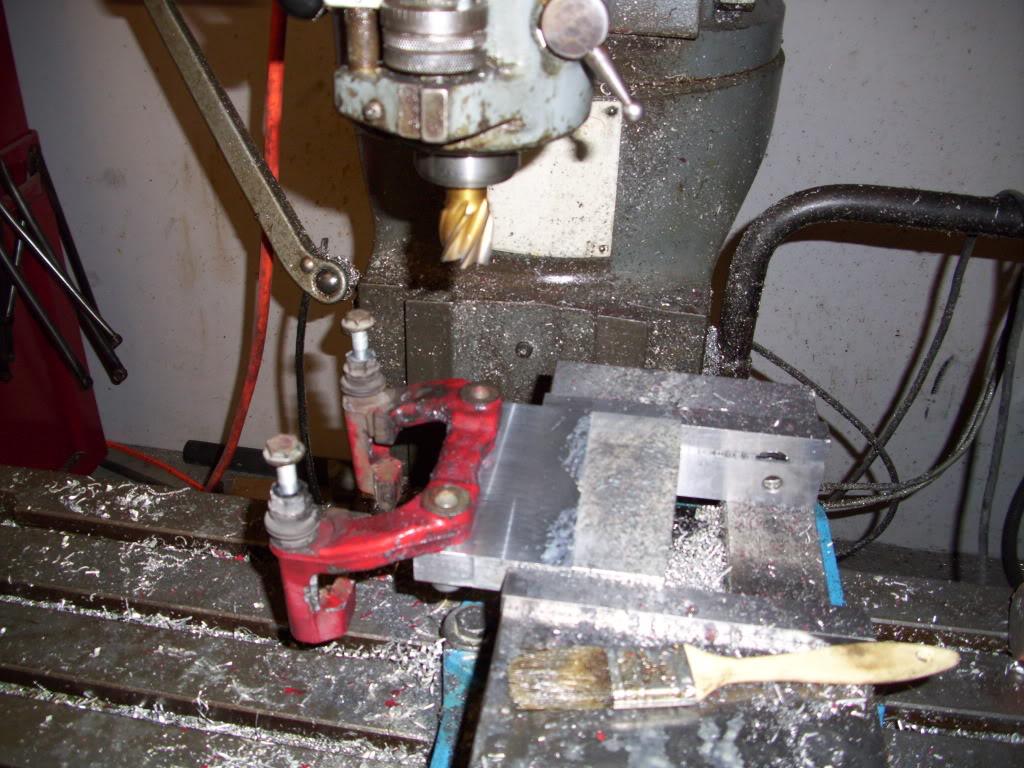
I managed to borrow some time on a milling machine for a few hours to do all this.
Here was the machining fixture I made first:
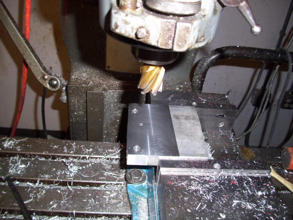
Milled the backside flat
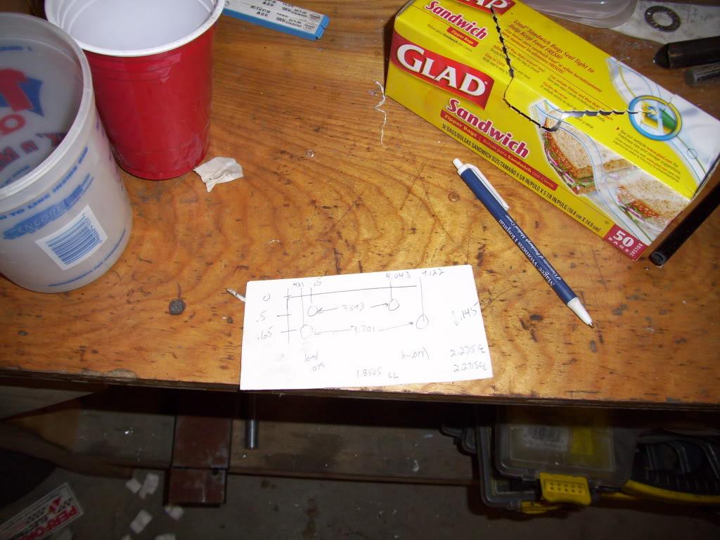
More carefully laid-out CAD model drawings
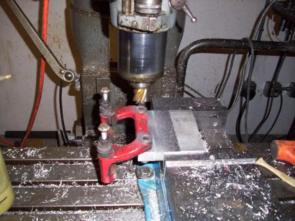
It fits!
July 13, 2009
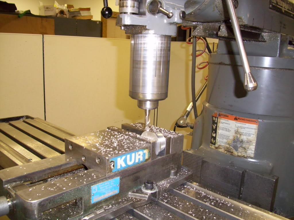
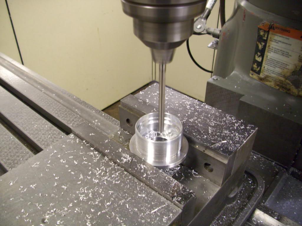
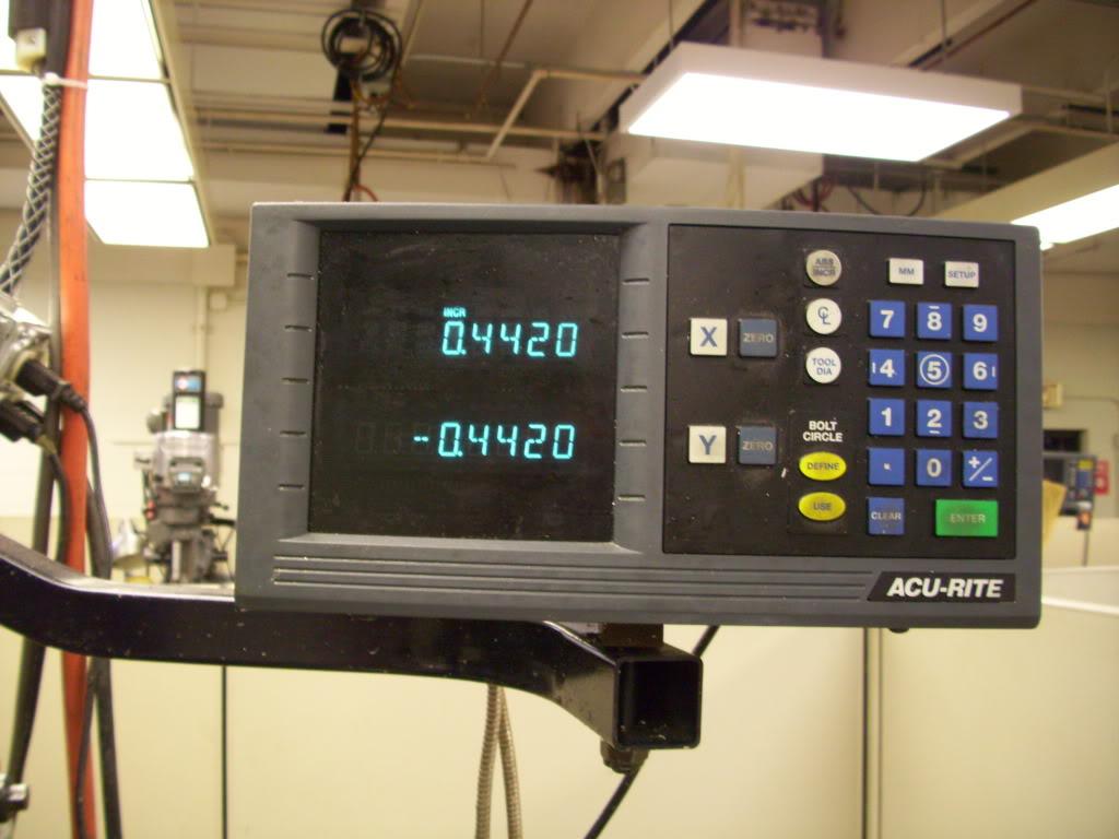
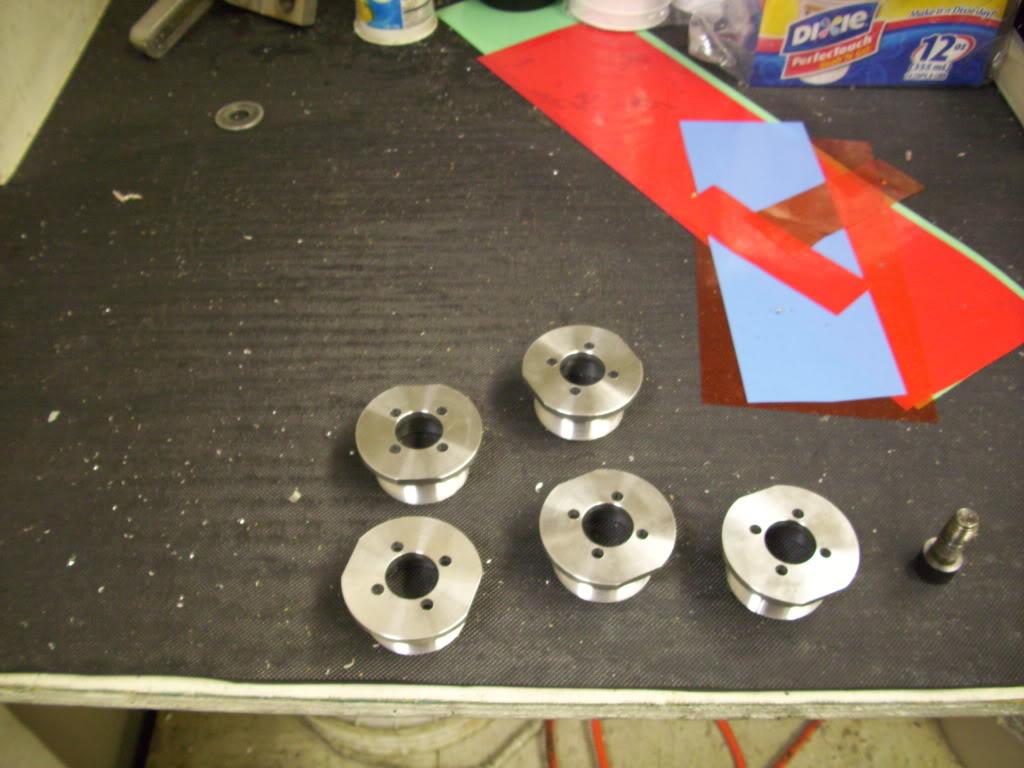
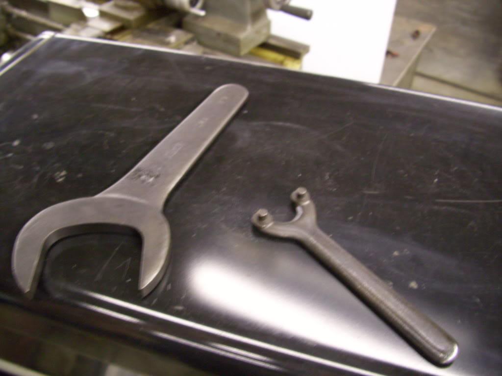
I stayed late at work to use a different mill and finish up the caps for the hydraulic pistons. Again, more on this later, but I had to drill the 4 holes for a spanner wrench then added wrench flats for a large wrench. This gives me the option of 3 different wrenching surfaces, in case one gets damaged, I can still get the pieces apart.
If any machinists are going to call me out on this setup, I know and I did it anyway and it was stiff enough for the tolerances I needed
All done!
July 15, 2009
I made this little bracket to mount the proportioning valves where they will tap into the stock brake lines.
July 20, 2009
I decided that the coupler for the fuel tank needed barbs instead of just clamping onto smooth tubing. I could have bought some, but was in a hurry so I just machined them on my craptacular lathe.
Had my buddy weld them on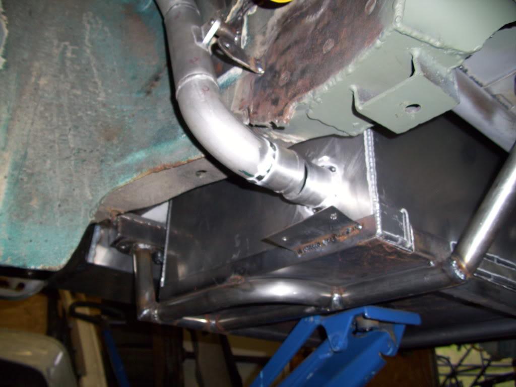
Look at all the parts piling up!
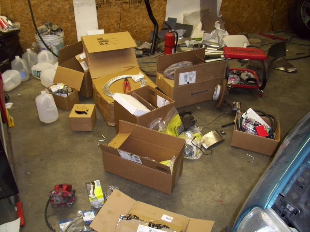
I ran into my first major f*ck up. Remember those real nice smooth bends in the fuel cell mounting bars? Well with the trunk floor in place, the tank couldn't be dropped without removing the subframe. I chopped them out and mitered in straight tubes for more clearance. I was not too happy. 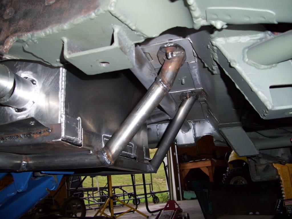
I also did a lot of finish welding on the floor and ground down some of the welds.
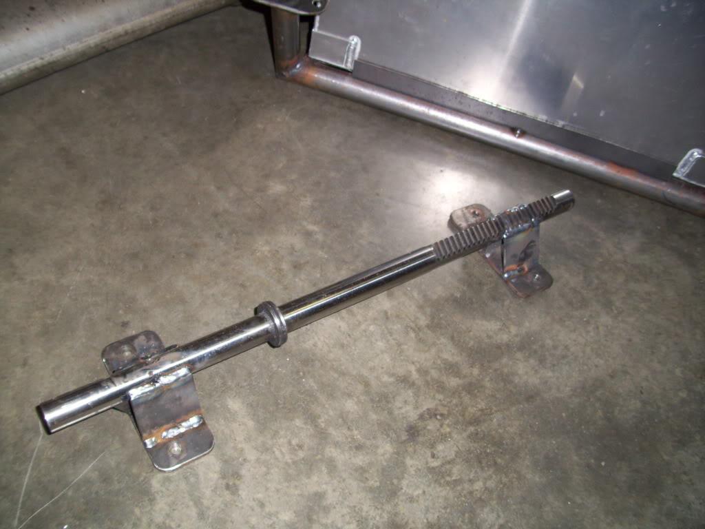
Since the rack was out and the welder was running, I took some time to reinforce the rack properly.
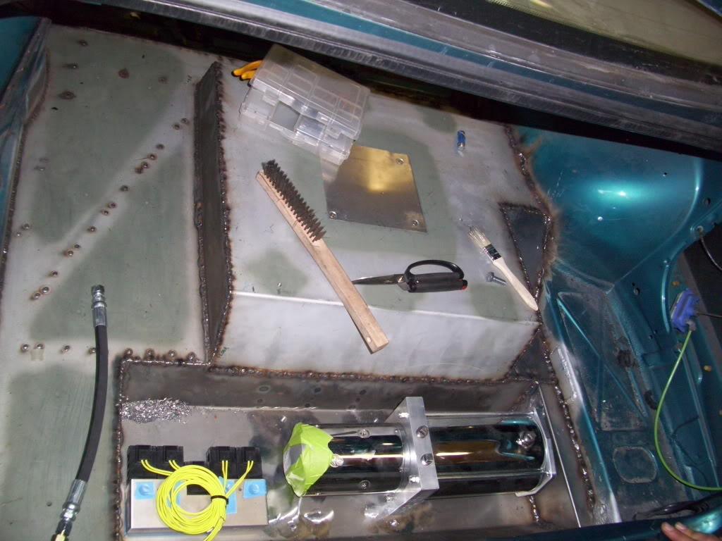
I also test-fit the hydraulic pump and valve manifold, trying to determine where exactly it would all mount. I had a few options using the mounts I had chosen.
July 21, 2009
I cut this little access hole for the vent hose to run up from the tank to the fillerneck.
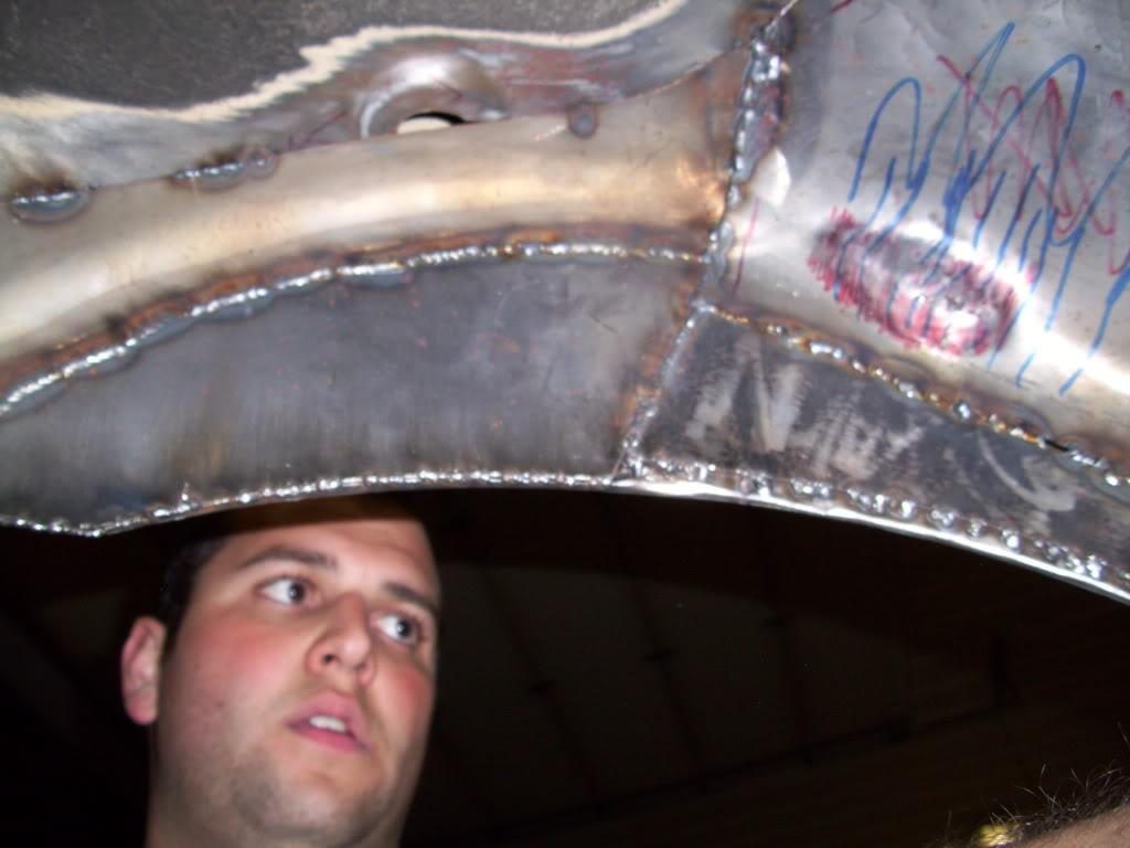
I did a lot of finish welding work on the rear wheel tubs, which had just been tacked up to this point. Yeah Myspace angle. I look so apathetic and tough.
July 27, 2009
I did some more finish welding on the tubs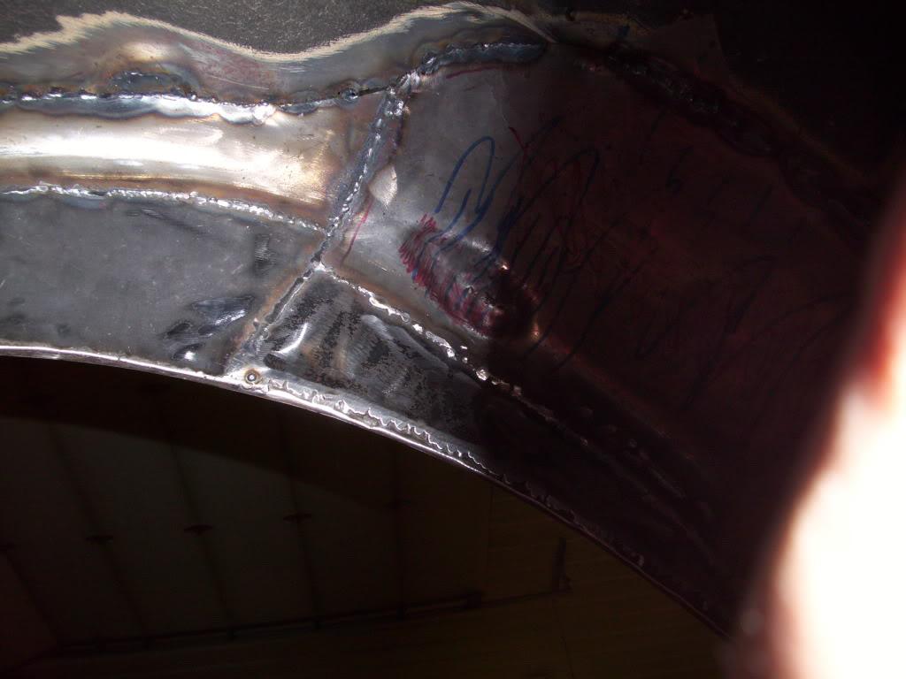
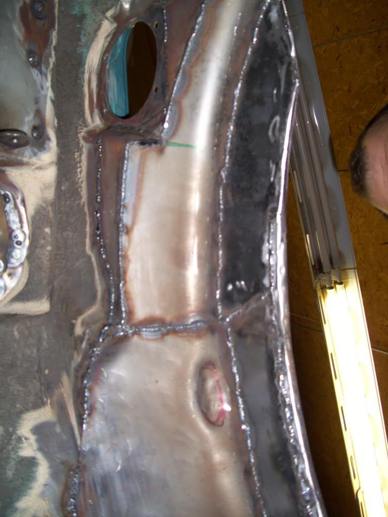
Note the little bump which is clearance for the door jambs. Every ounce of space was taken!
I pressure washed the suspension components and painted them with ChassisSaver semi-gloss black.
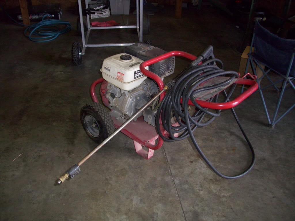
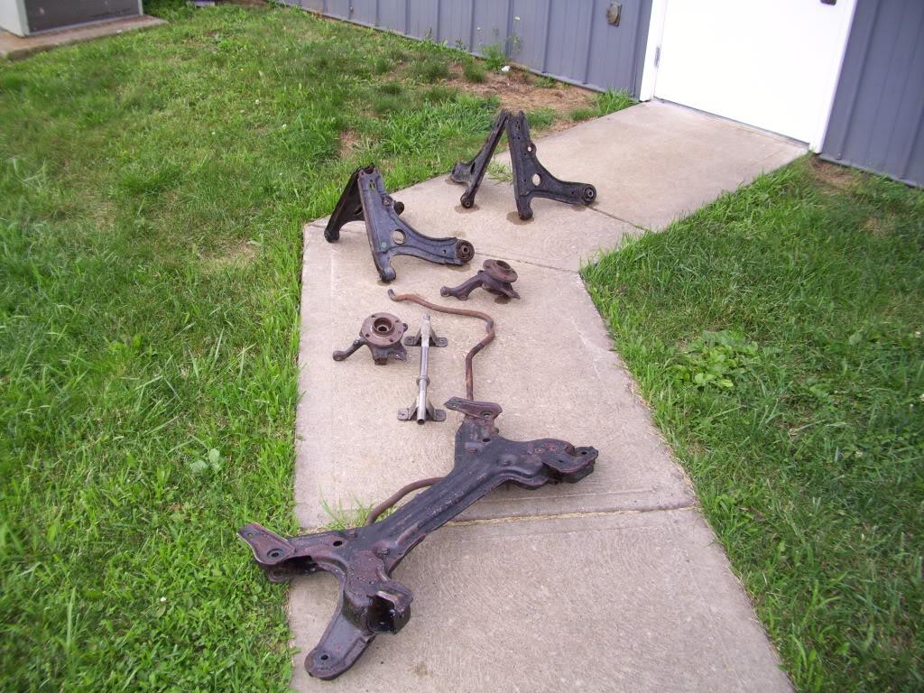
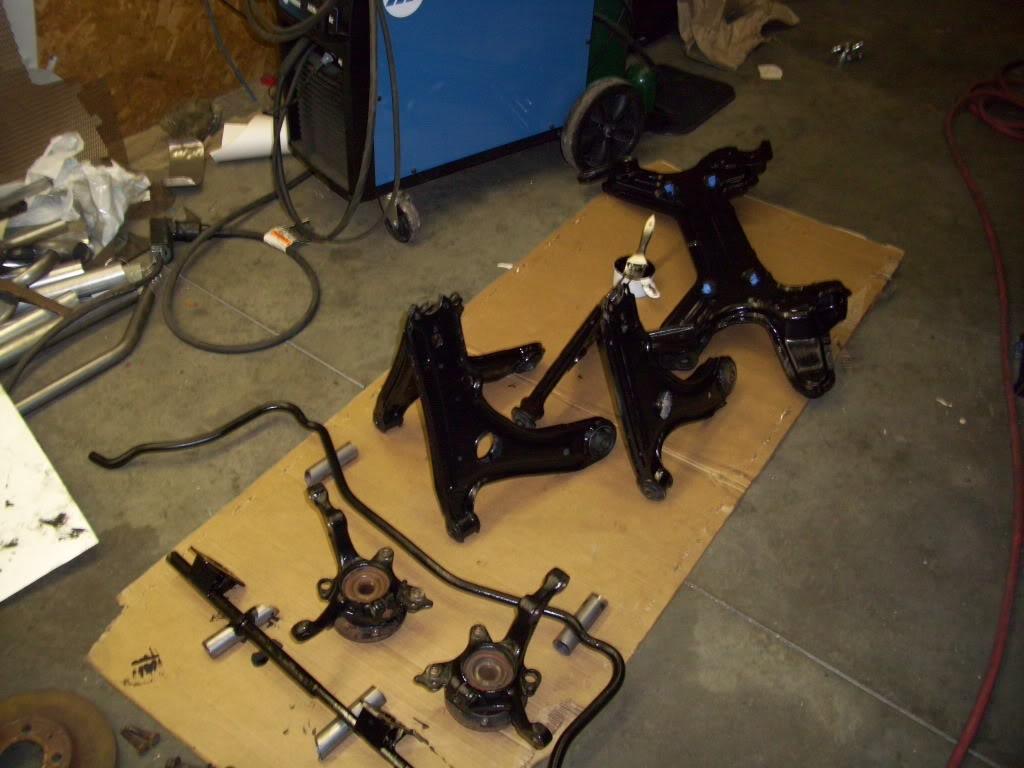
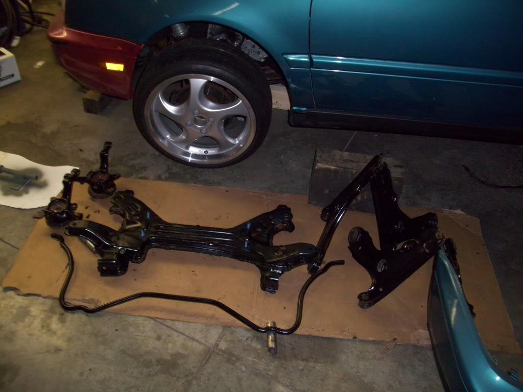
I also used the ChassisSaver (Similar to POR15) around the filler door, which still had some light traces of rust that I couldn't remove.
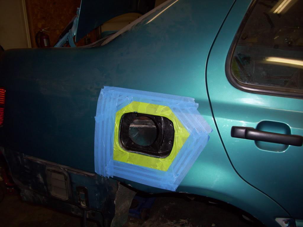
I cleaned and primered some parts of the trunk floor also
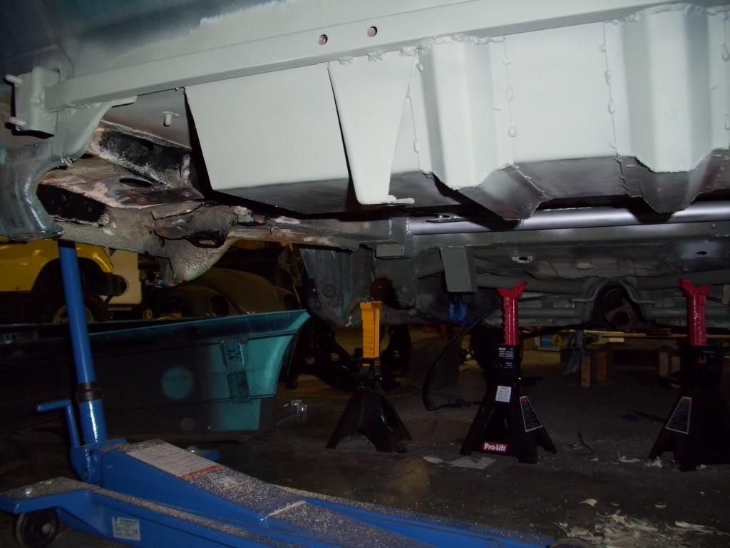
Ground down the welds and cleaned the rack
July 28, 2009
I got the passenger side rear tub all cleaned and in primer
Creepin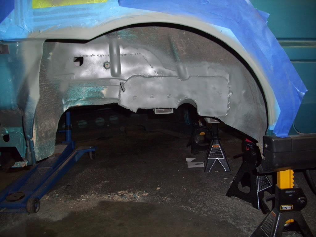
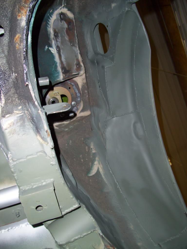
July 30, 2009
Cleaned and primered the drivers side tub
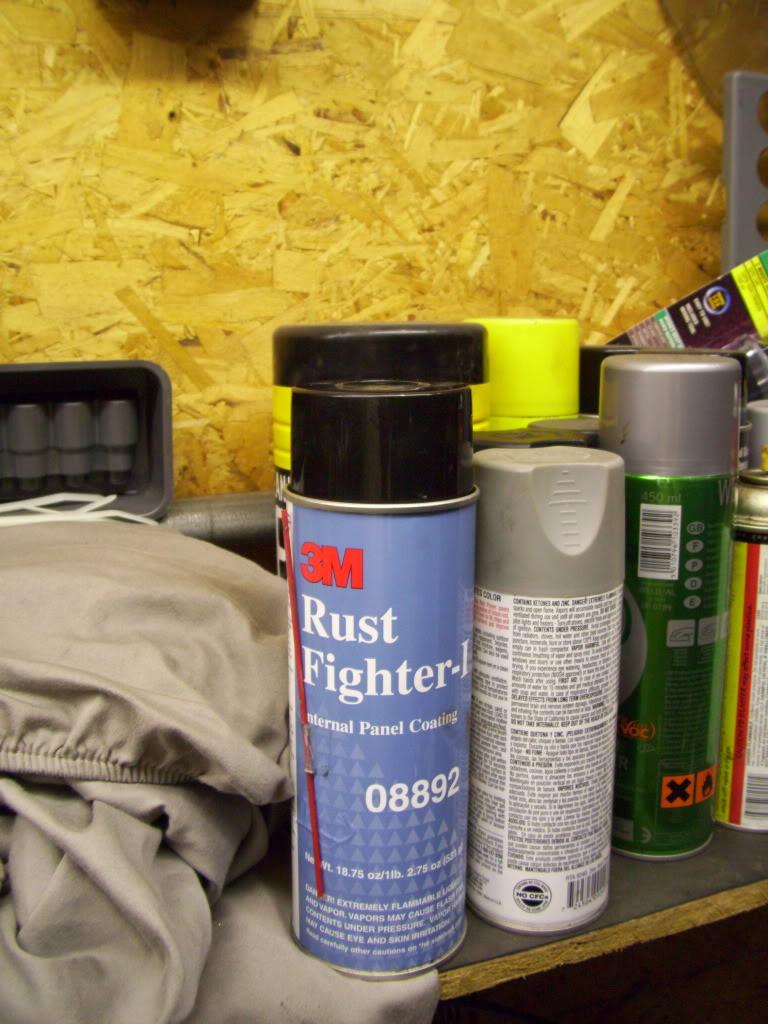
I drilled a bunch of access holes and used 3M Rust Fighter internal panel rust inhibitor. These holes were plugged later with 3/8" rubber plugs and seam sealed over. This is to prevent the new fabbed stuff from rusting from the inside out.
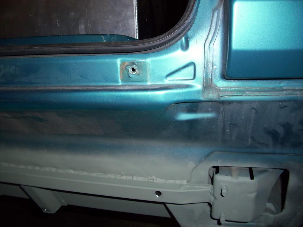
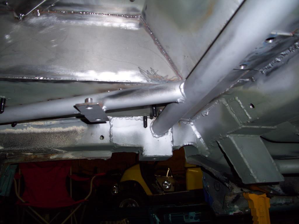
That's all for tonight, I will begin August 09 tomorrow evening.
August 1, 2009
Got the fuel tank tray in primer
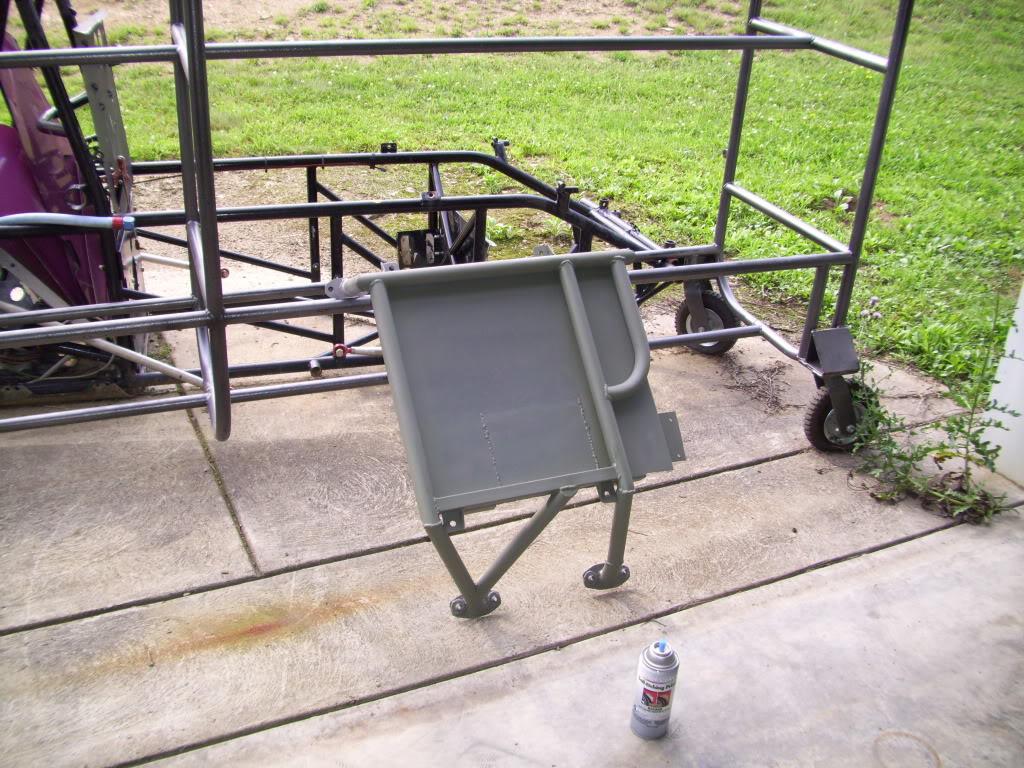
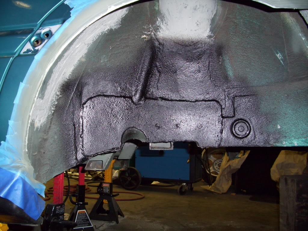
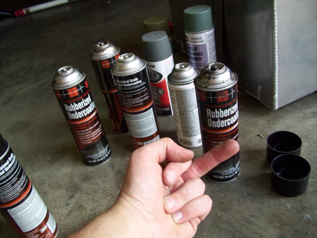
Tested out the 3M undercoating I bought
I got my new wheel bearings and hubs and lots of hardware from GAP for the new rear suspension.
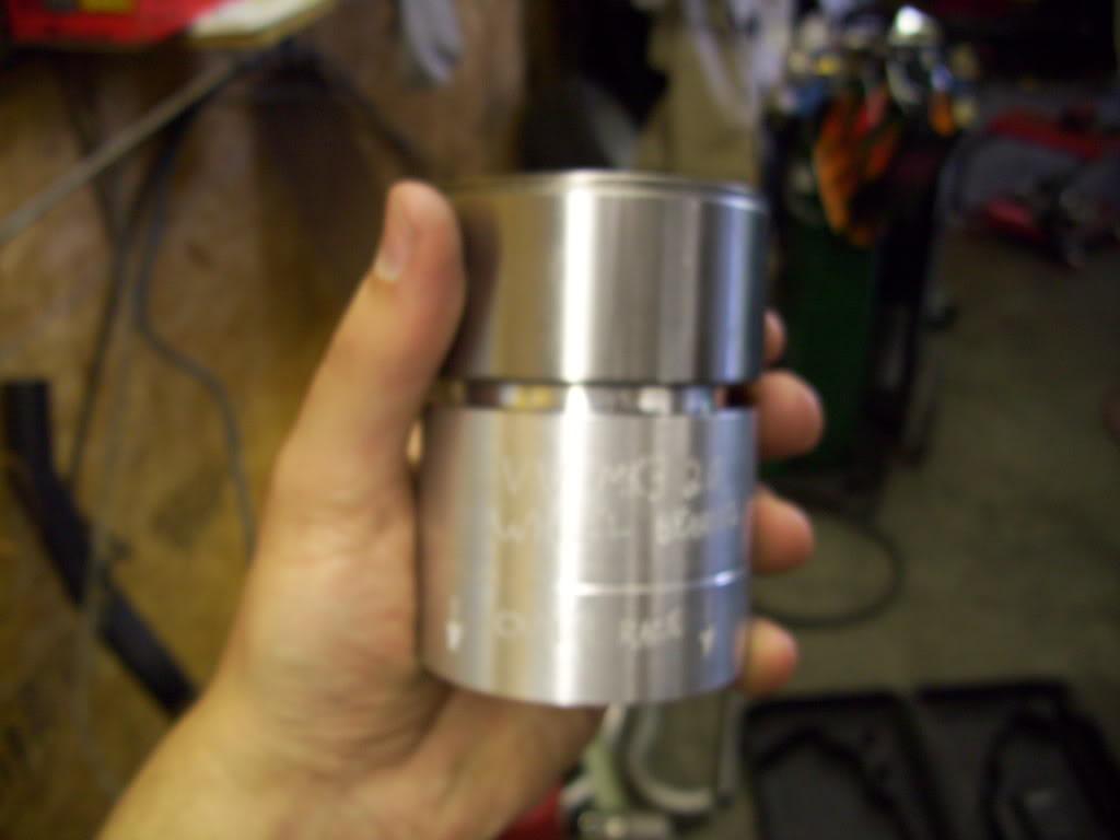
I made this wheel bearing press tool. One side is sized for the outer race, which pushes the bearing into the spindle:
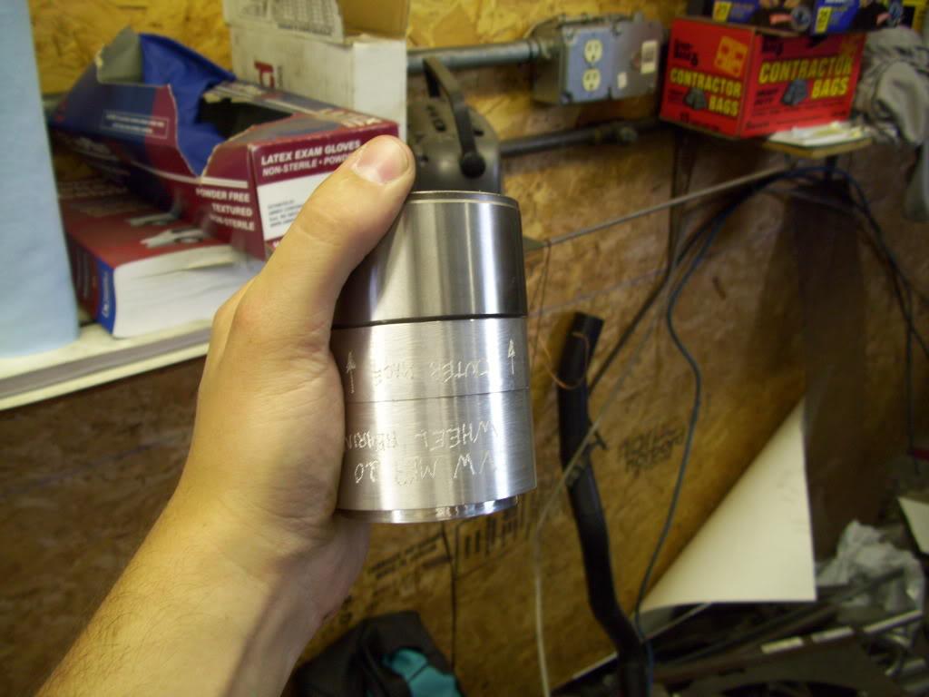
The other side is sized for the inner race which presses the hub into the bearing:
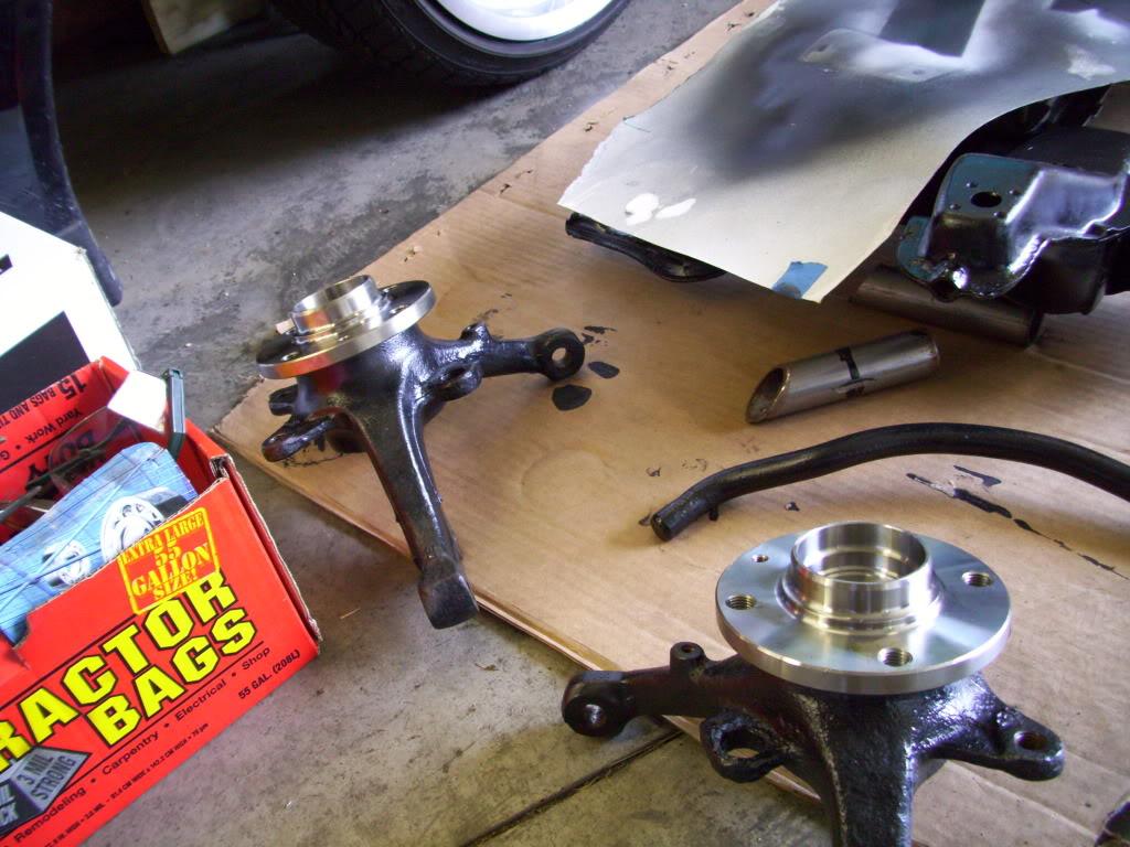
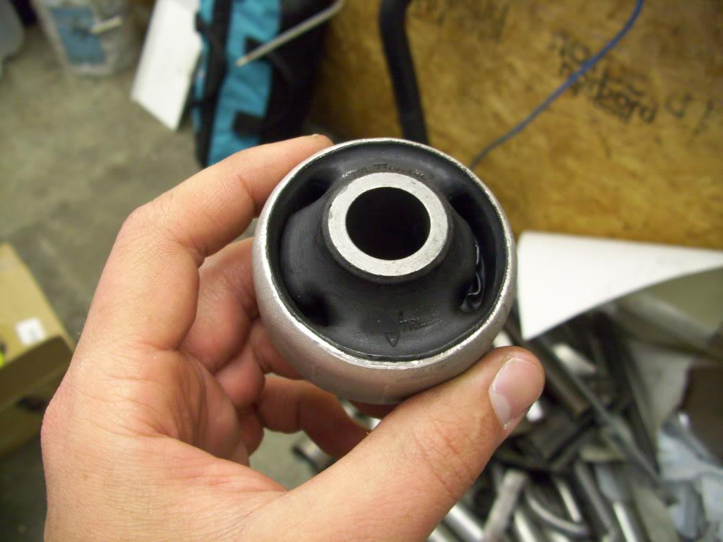
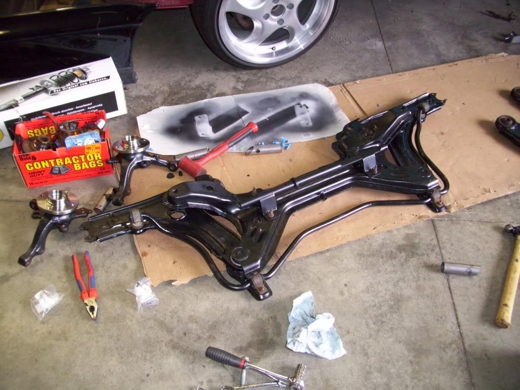
Rear bushing are still rubber. I pressed these into the mk3 control arms. More on that later
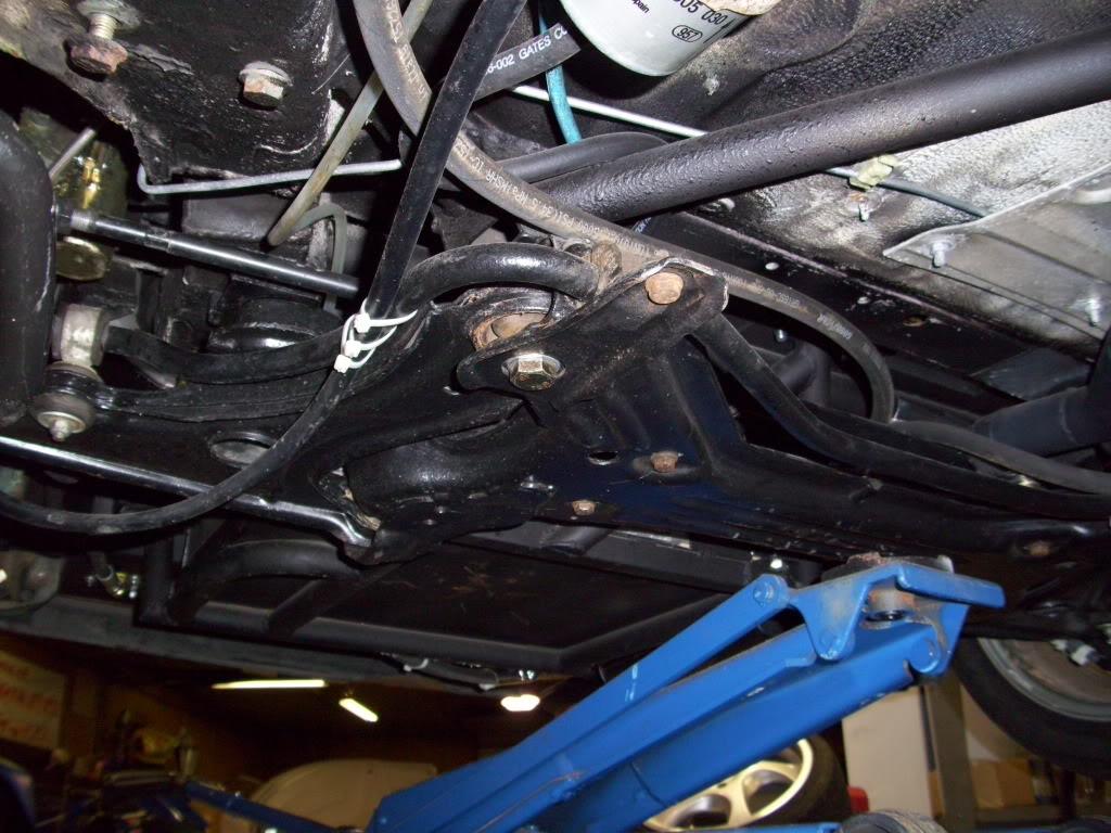
Got the rear subframe partially assembled
August 2, 2009
More paint!
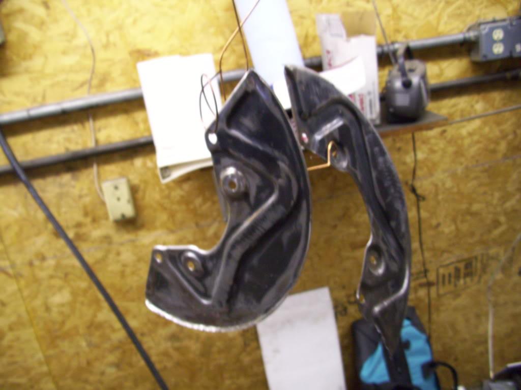
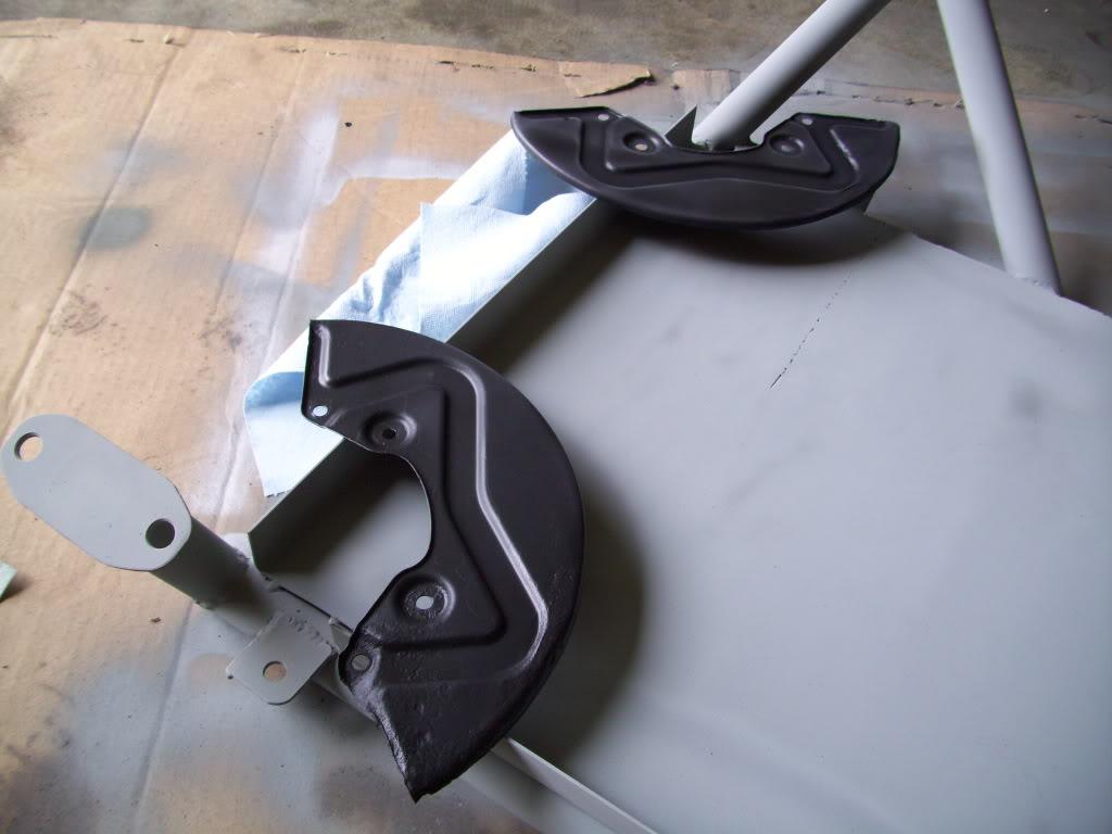
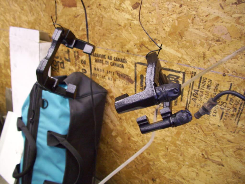
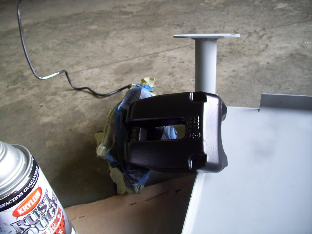
I intentionally did a half-assed job painting the rear calipers, because they need rebuilt soon and will be powdercoated black properly. Crappy paint is easier to strip in the future!
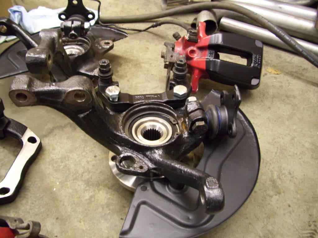
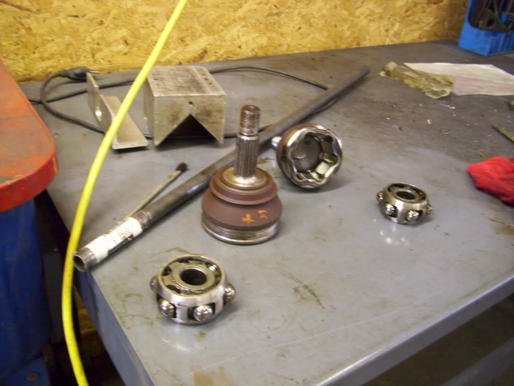
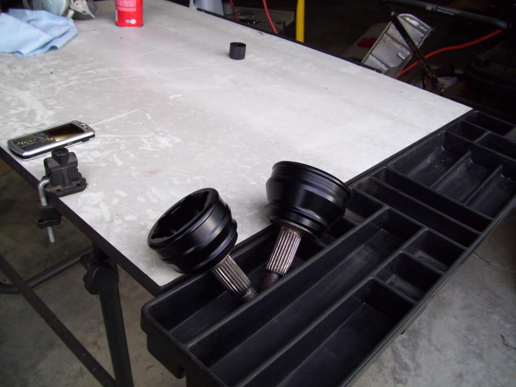
To keep the wheel bearings properly preloaded so they can actually work, you need to keep them clamped. The outer CV joint has this feature built in, so rather than build something fancy I just stole two outer CV joints I had laying around.
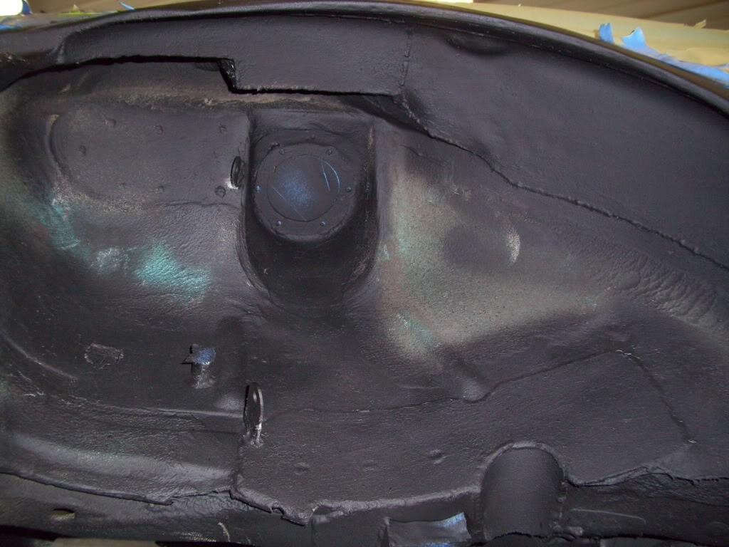
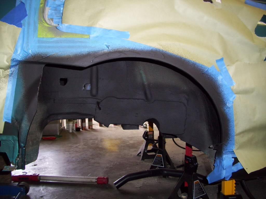
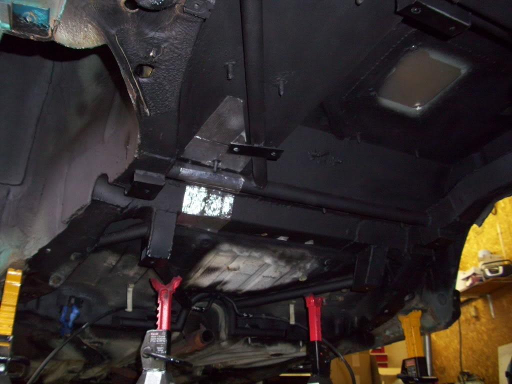
I did a lot of undercoating, seam sealing, painting, cleaning...
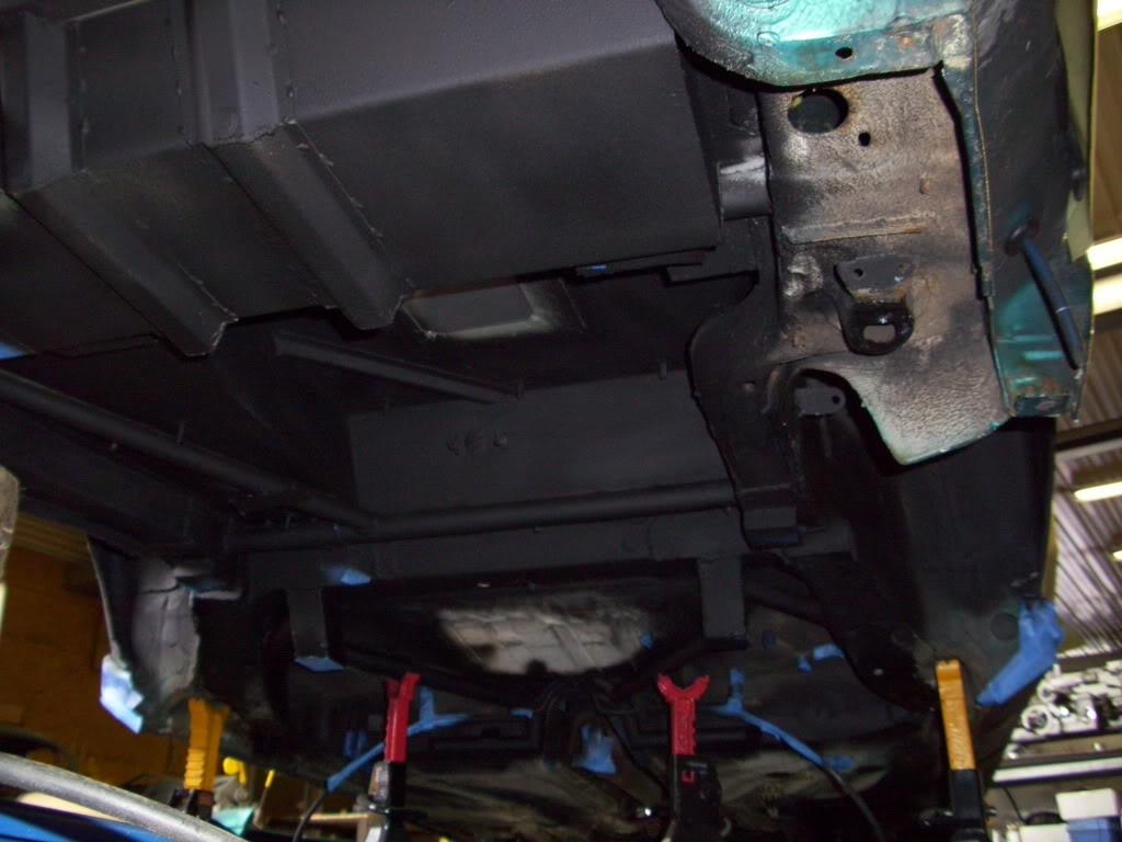
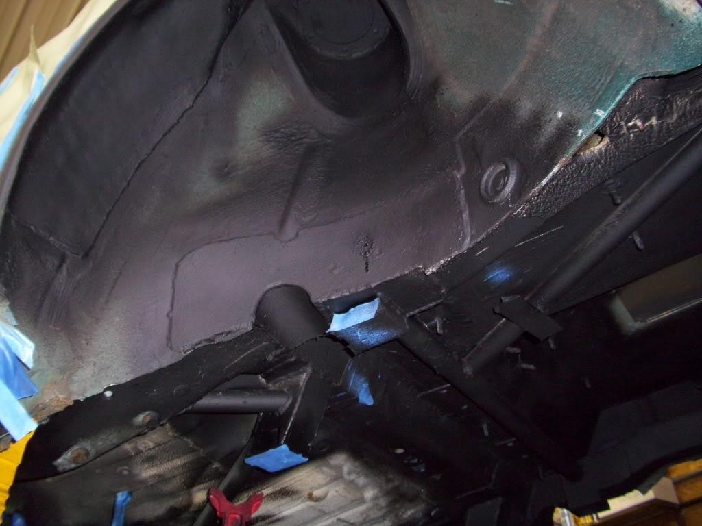
Stuck on some adhesive-back heat resistant sheets to protect the floor in the areas of the exhaust
August 4, 2009
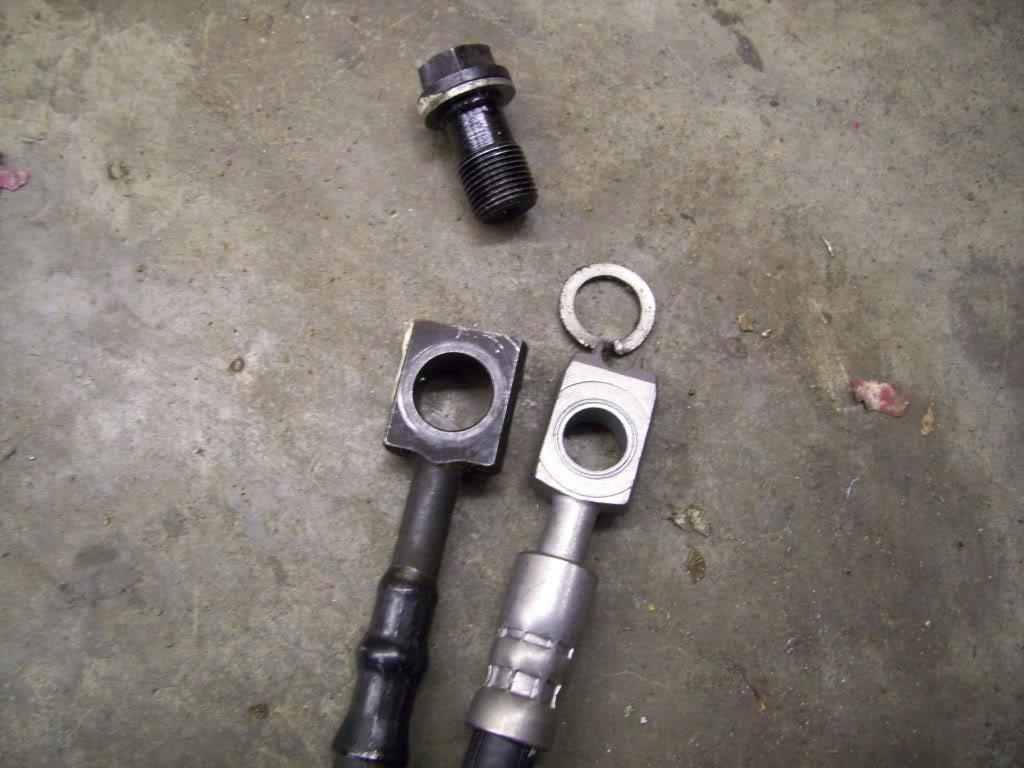
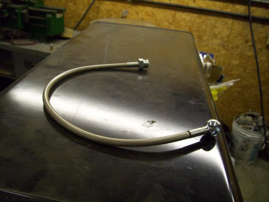
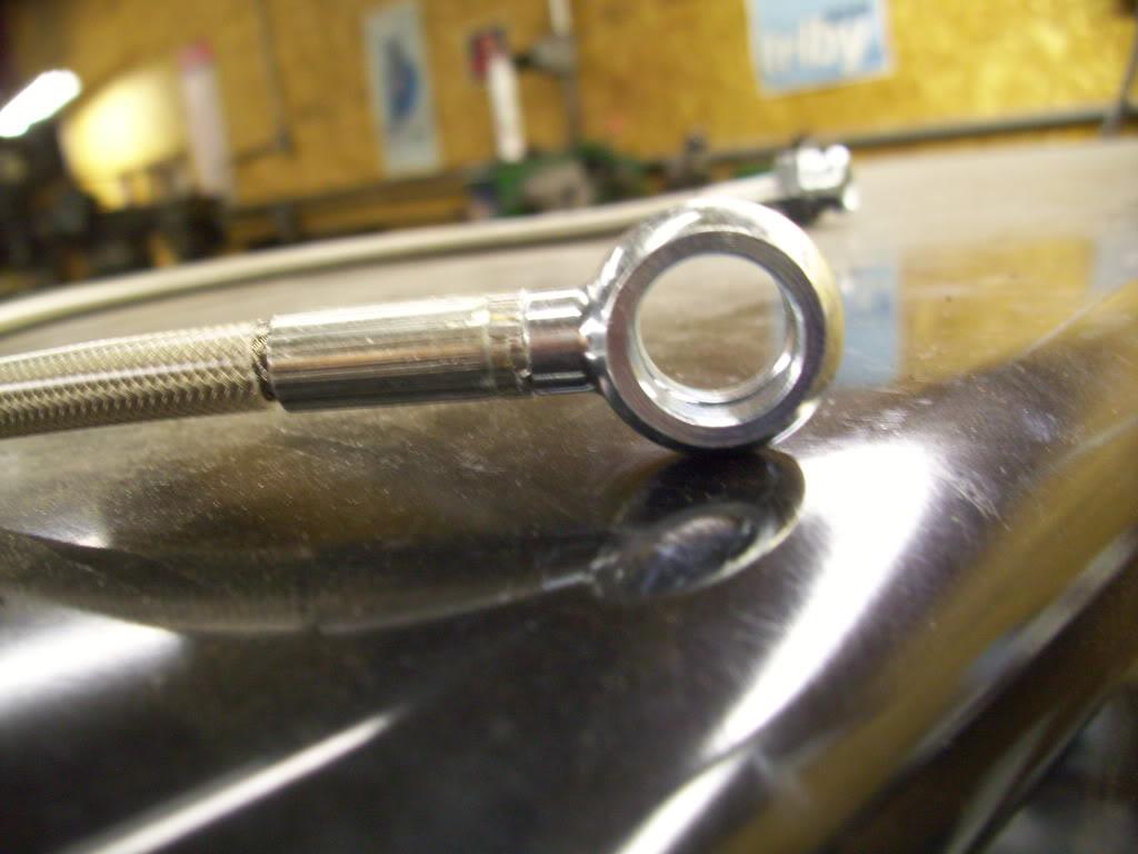
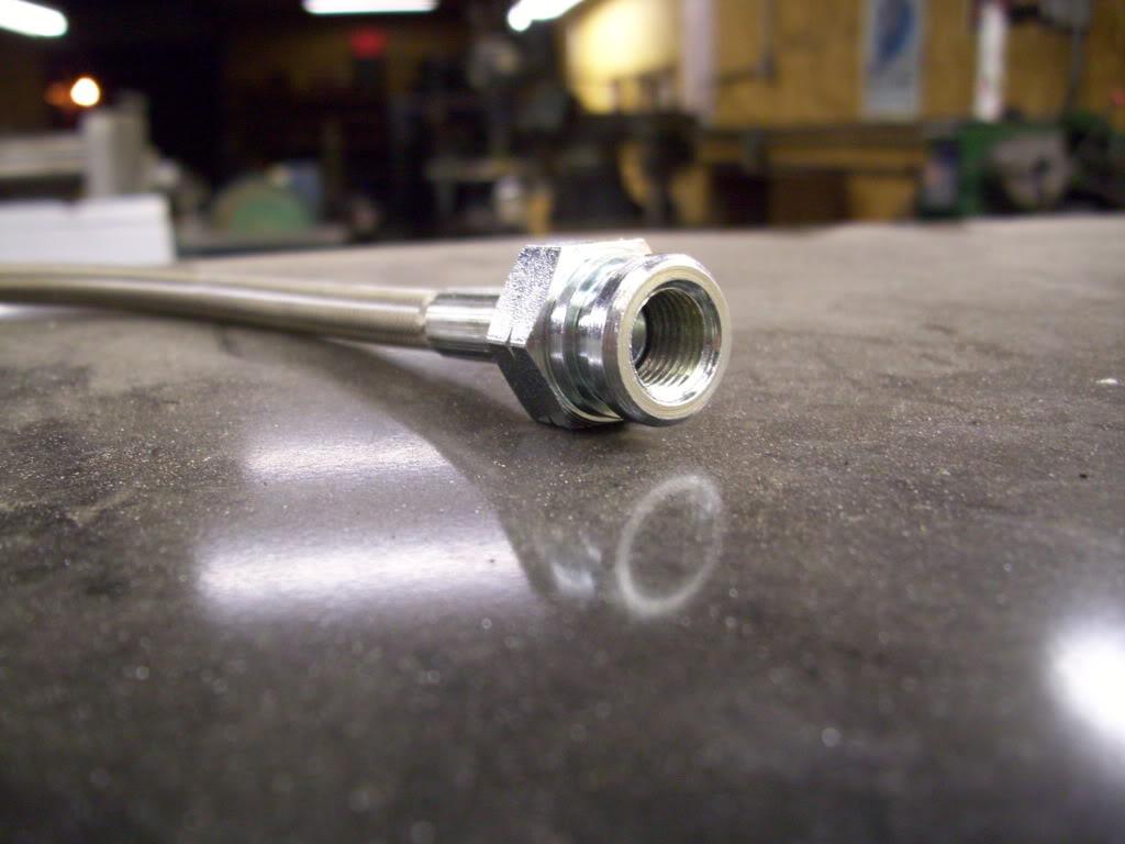
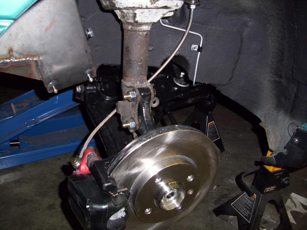
I realize the mk4 front brake hoses I purchased would not work on the mk4 GLI rear calipers. I couldn't use the mk4 GLi rear brake lines because they're not flex lines, and I assumed the banjo bolts would be the same size front and rear. They're not, so I had to order a custom steel braided brake hose for the rear.
The mk4 GLI rear brake hose on the left uses a 12mm bolt, the mk4 front brake hose on the right uses a 10mm bolt. It can't just be drilled.
August 5, 2009
Got the trunk floor all in primer
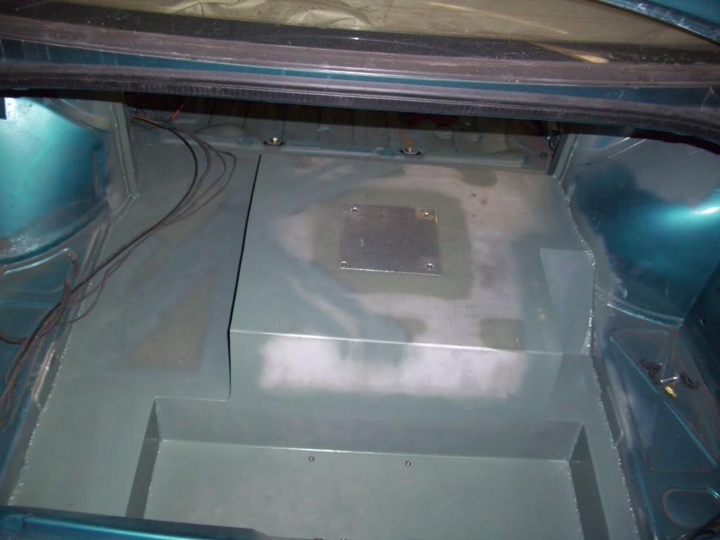
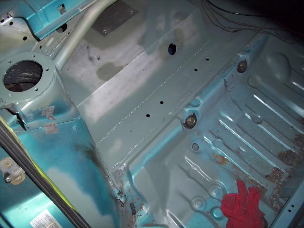
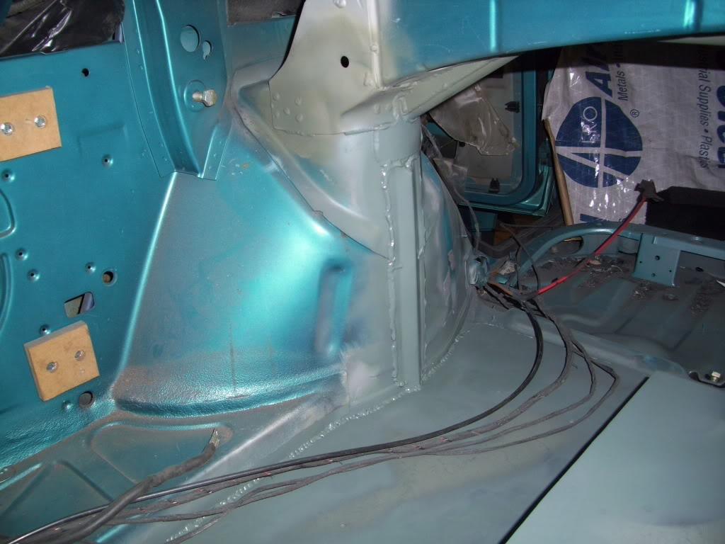
A few days prior, I forgot to take pics, I welded in these stiffening ribs to strengthen the rear towers a little bit. They admittedly don't add much, but I wanted to keep it low profile so I could hide everything under carpeting in the future. Every little bit counts, and they didn't take long to make, so why not?
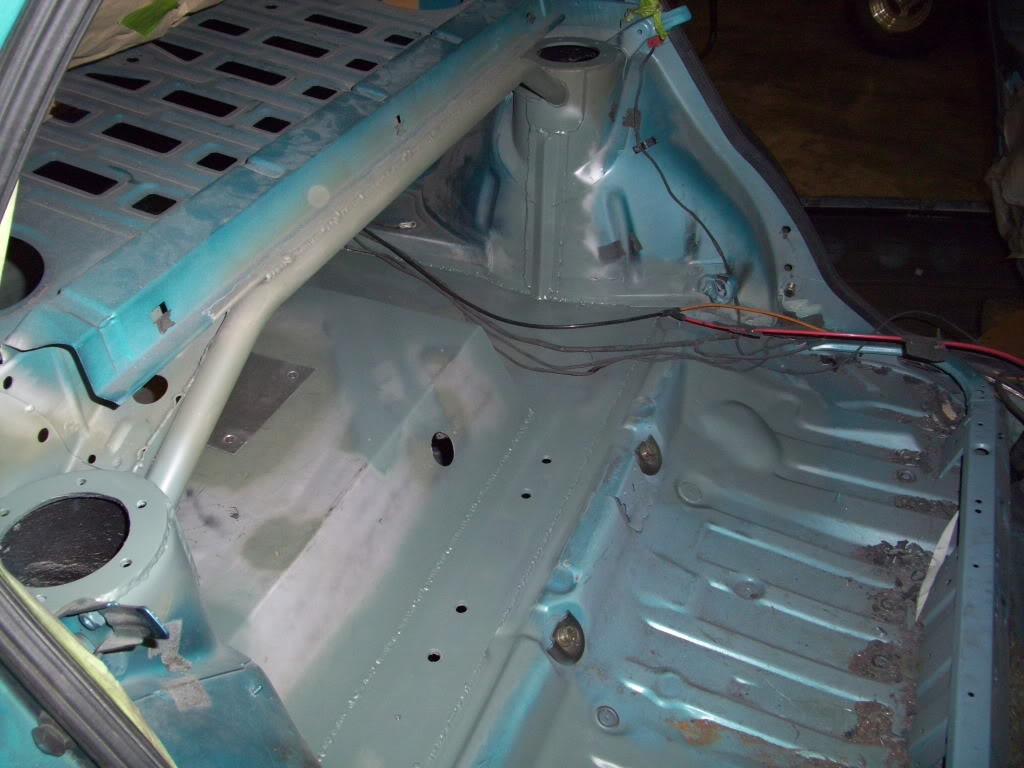
August 11, 2009
Started routing the rear brake hard lines
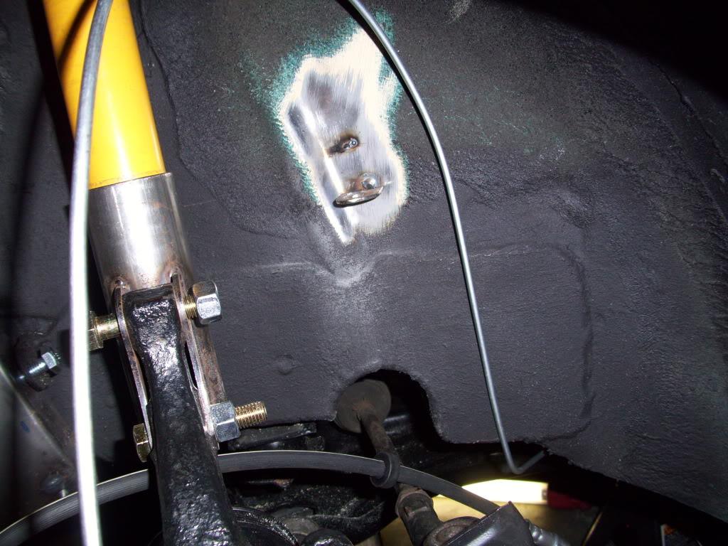
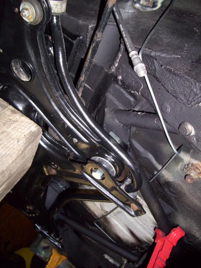
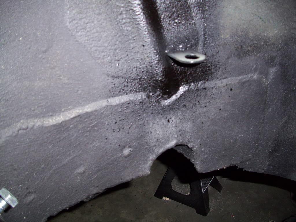
August 13, 2009
Got the tabs welded onto the rear wheel wells to hold the brake lines.
Got my new custom brake hoses. $100 for the pair from Detroit Flexible Metal, custom to my specs. I think they were 18" long, female flare on one side and 12mm banjo on the other.
August 16, 2009
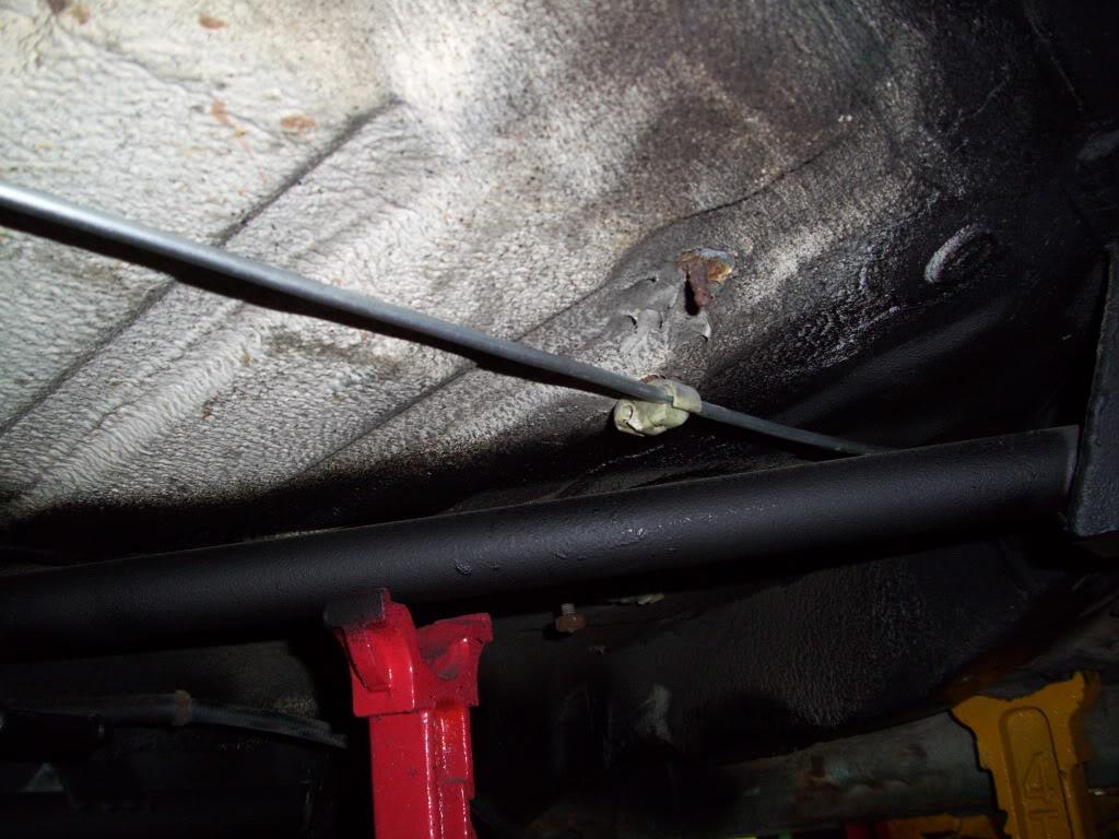
I got the hard lines finished up.
The brakes feel fine, and I think I got most of the bubbles out, but I'm not so sure about the way I chose to route this part. Will this collect bubbles that won't bleed out? I have a Motive pressure bleeder if that matters.
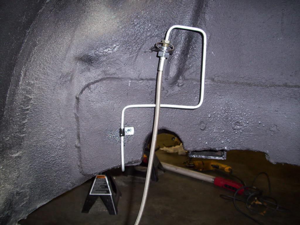
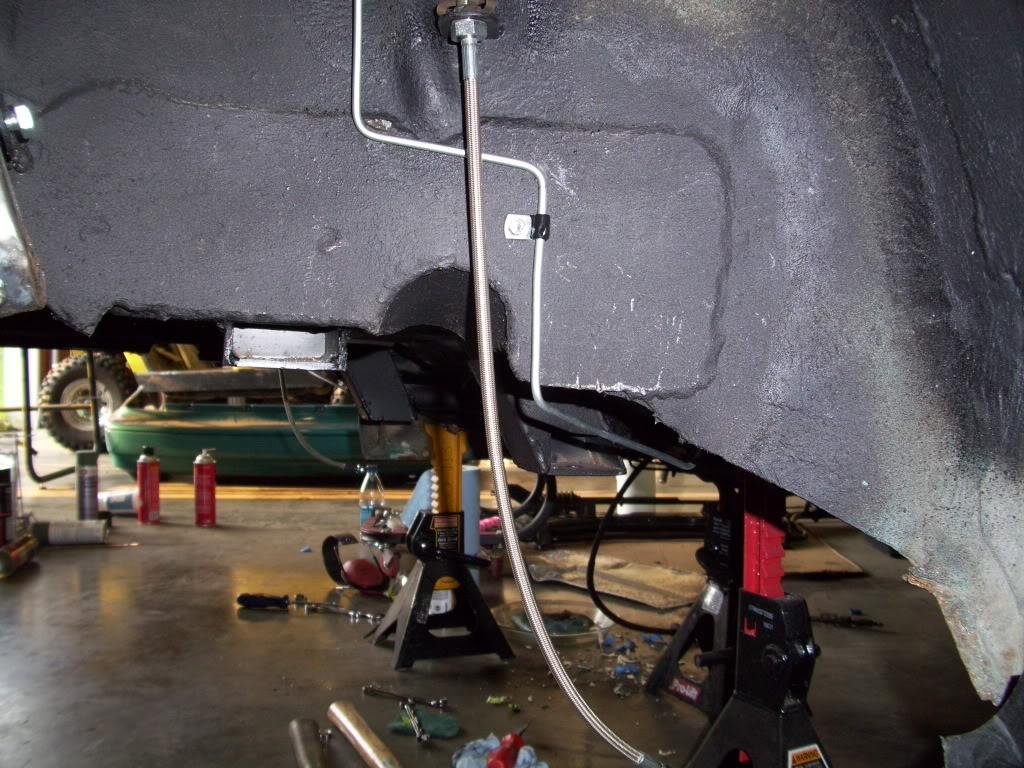
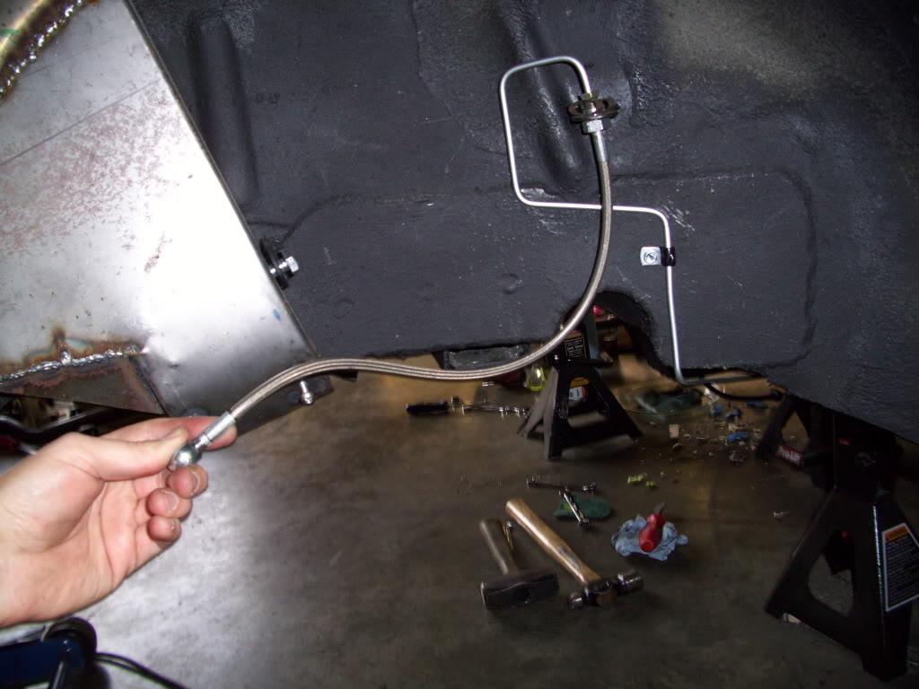
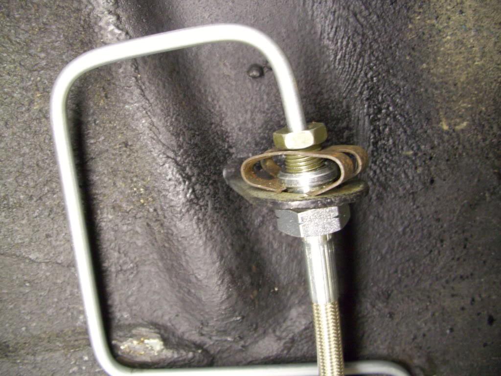
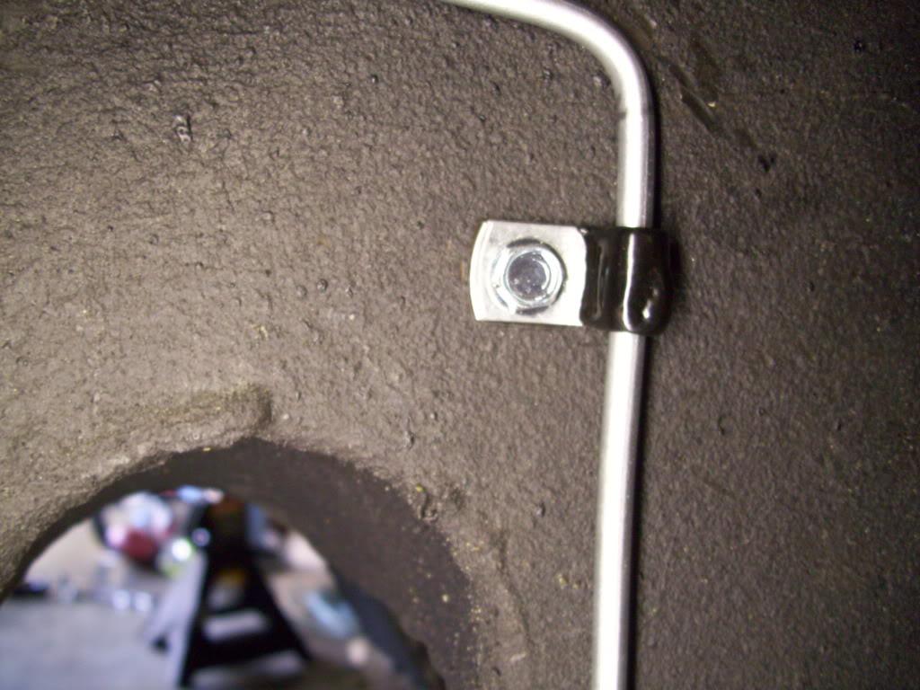
I got the two Wilwood proportioning valves mounted and plumbed
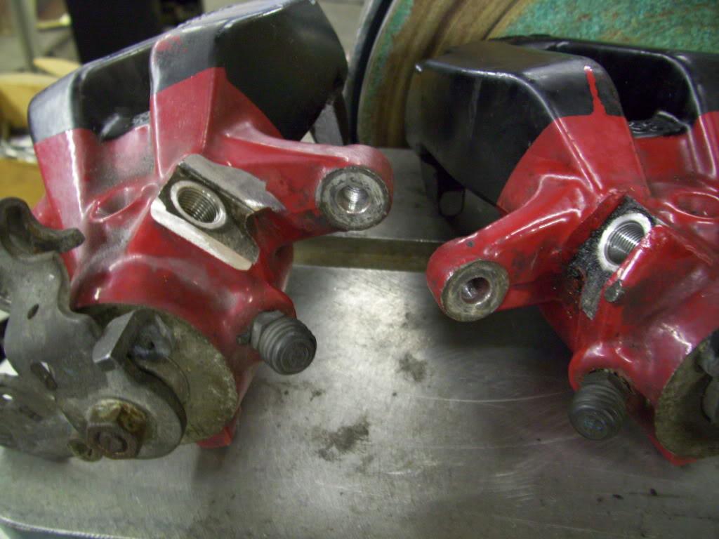
I had to grind down the ridges on the caliper to fit the new banjo, which is shaped differently than the stock banjos. Before on the right, After on the left
I did a bunch of reassembly work. I'm using four stock mk3 front struts just to roll the car around. No springs, just some bumpstops to hold it up but still pretty low.
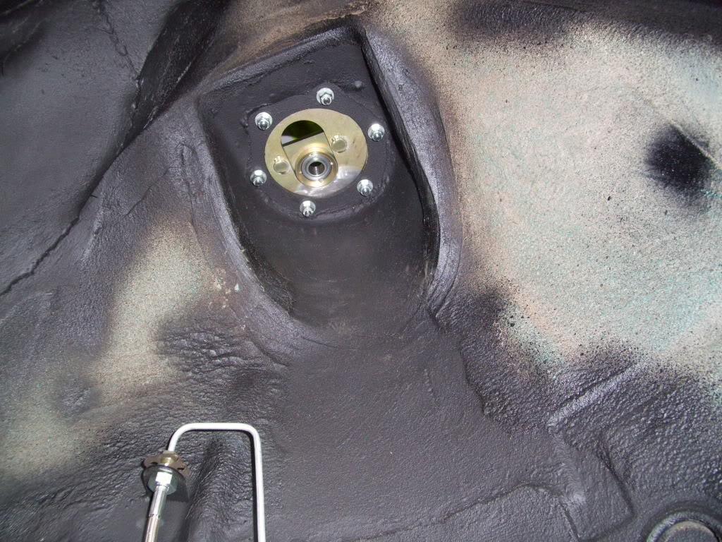
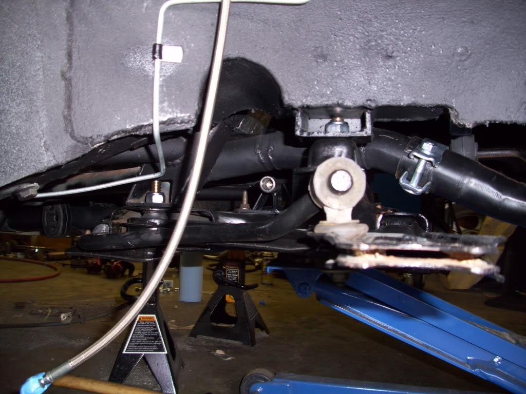
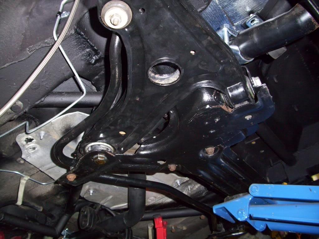
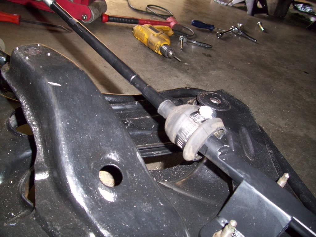
Figured out a boot for the inner tie rod, which is just a cut down stock tie rod boot clamped on. It just has to pivot since the rear doesn't steer anymore I don't need the whole boot.
August 17, 2009
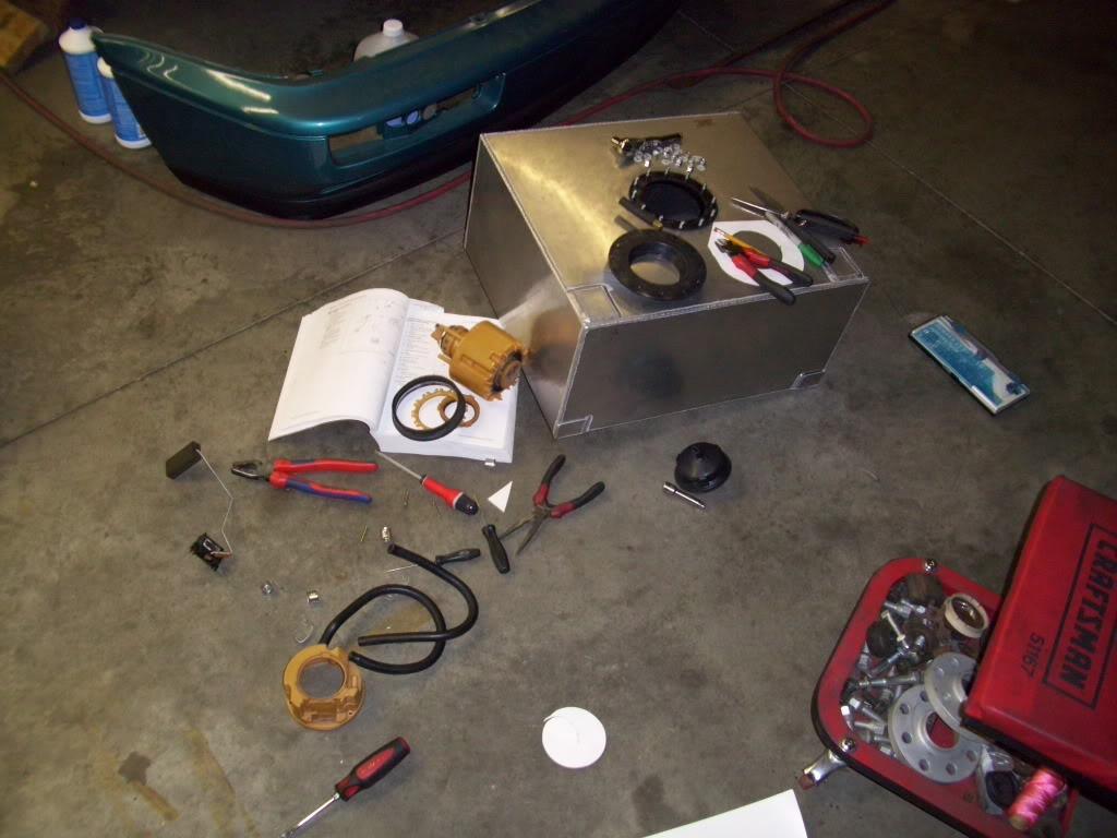
Did some planning on the fuel pump wiring/plumbing bulkhead.
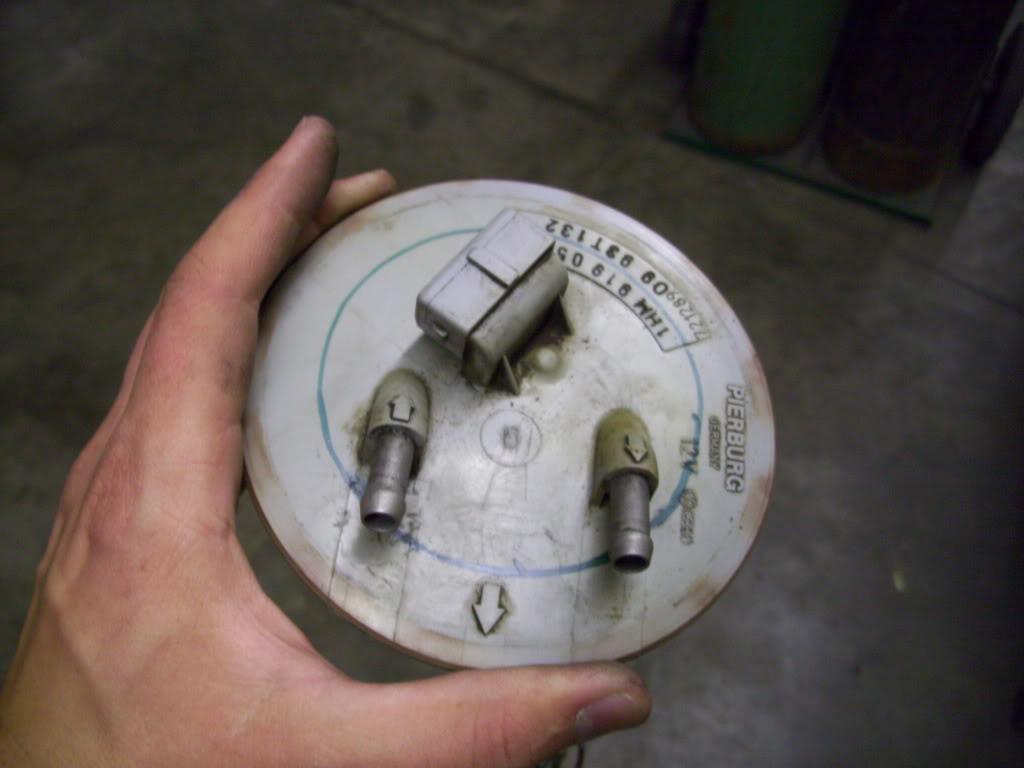
August 19, 2009
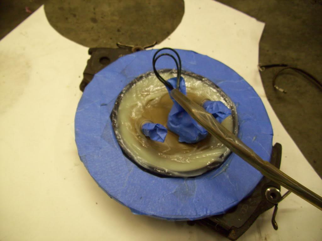
I made the fuel bulkhead using epoxy. I bonded an aluminum ring I cut out to help give it more strength.

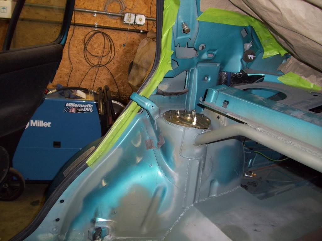
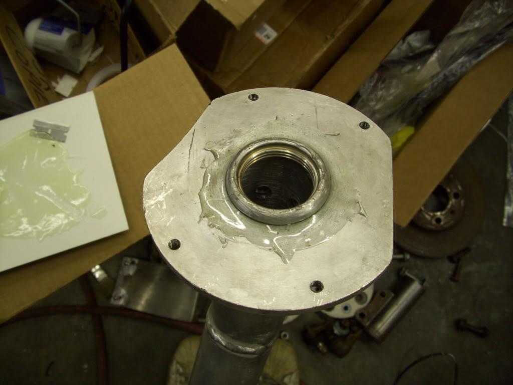
This joint by the fuel filler couldn't be welded because the threads were too close to the edge, so I epoxied it. It's welded on the inside, but bubbled slightly under the pessure test so I epoxied it up just in case.
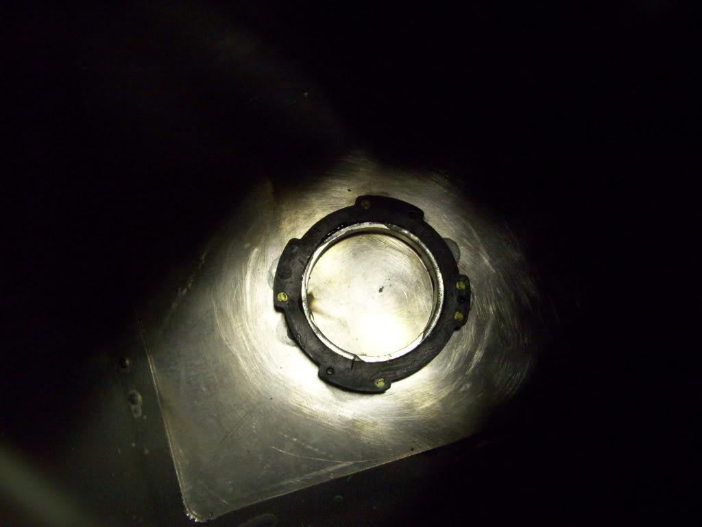
I also bonded the ring for the fuel pump mounting down inside the tank using more epoxy
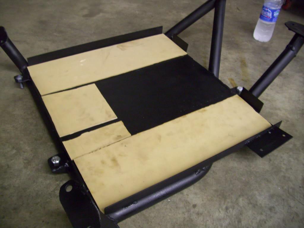
Made a rubber gasket pad for under the fuel cell so it doesn't get scuffed vibrating around in its tray
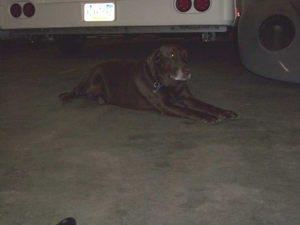
Gunner, my buddy's dog, chillin.
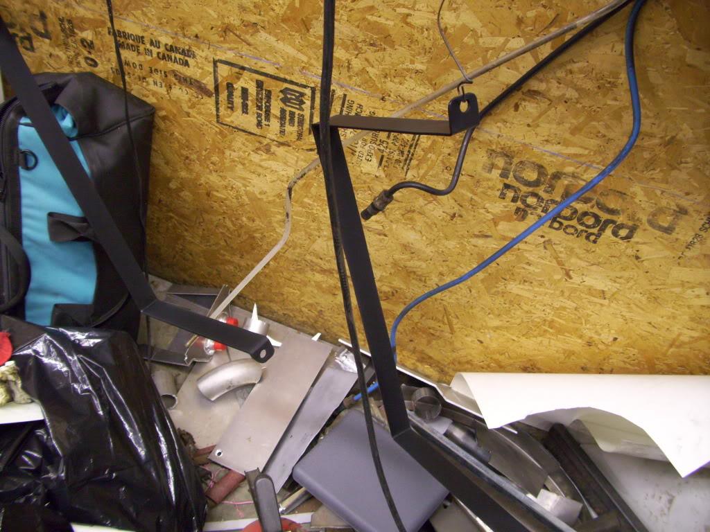
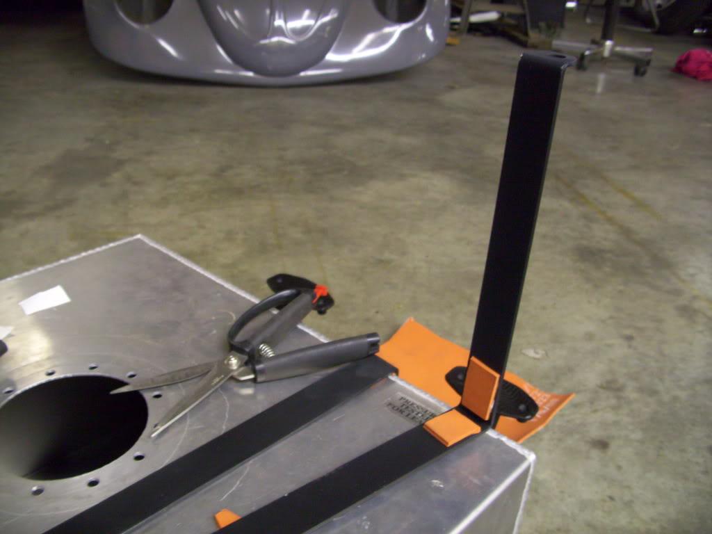
Made some straps to hold the fuel cell down to its tray and padded the corners with silicone rubber
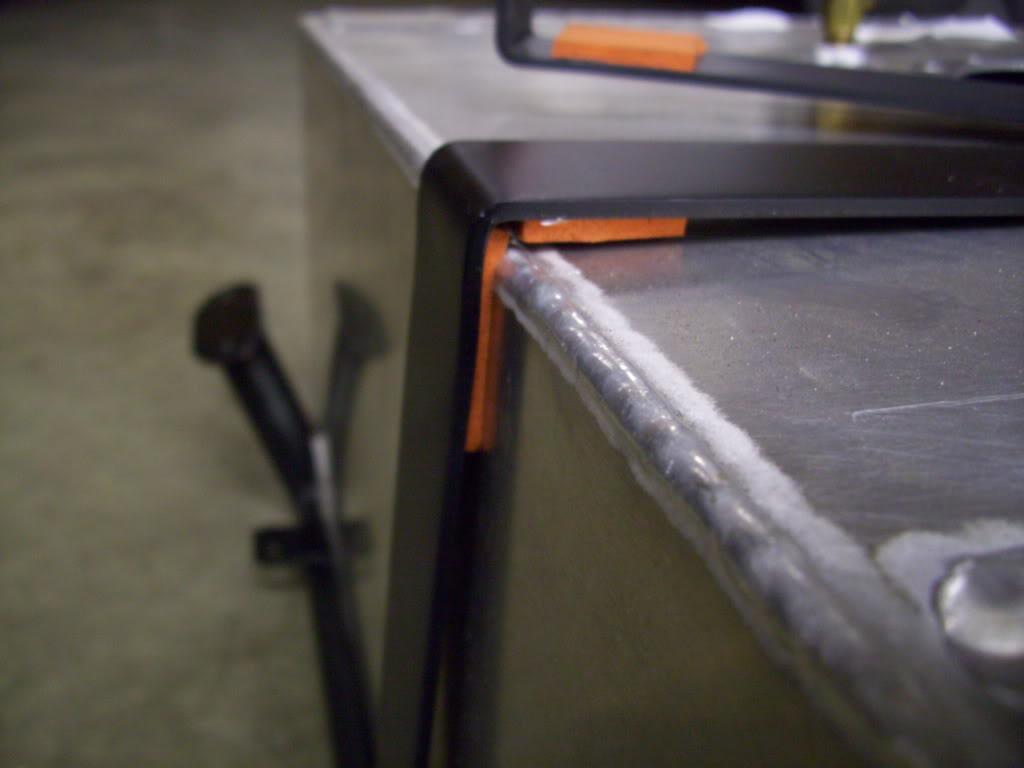
August 20, 2009
I got some fuel foam and filled up the tank, trimming it around the fuel pump. This keeps the fuel from sloshing around since there is no baffeling in the tank. It's not a race car.
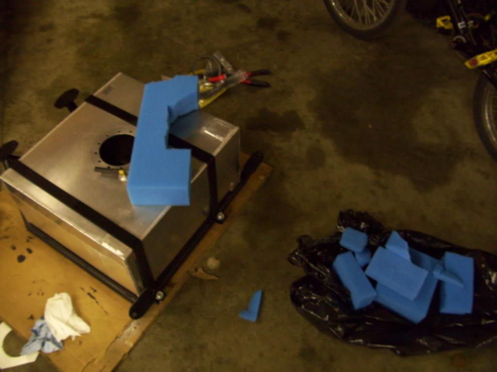
Got the fuel cell assembly all strapped in and assembled

I pressure tested it. I used dog shampoo because I didnt have any dish soap. But no bubbles - all sealed up!
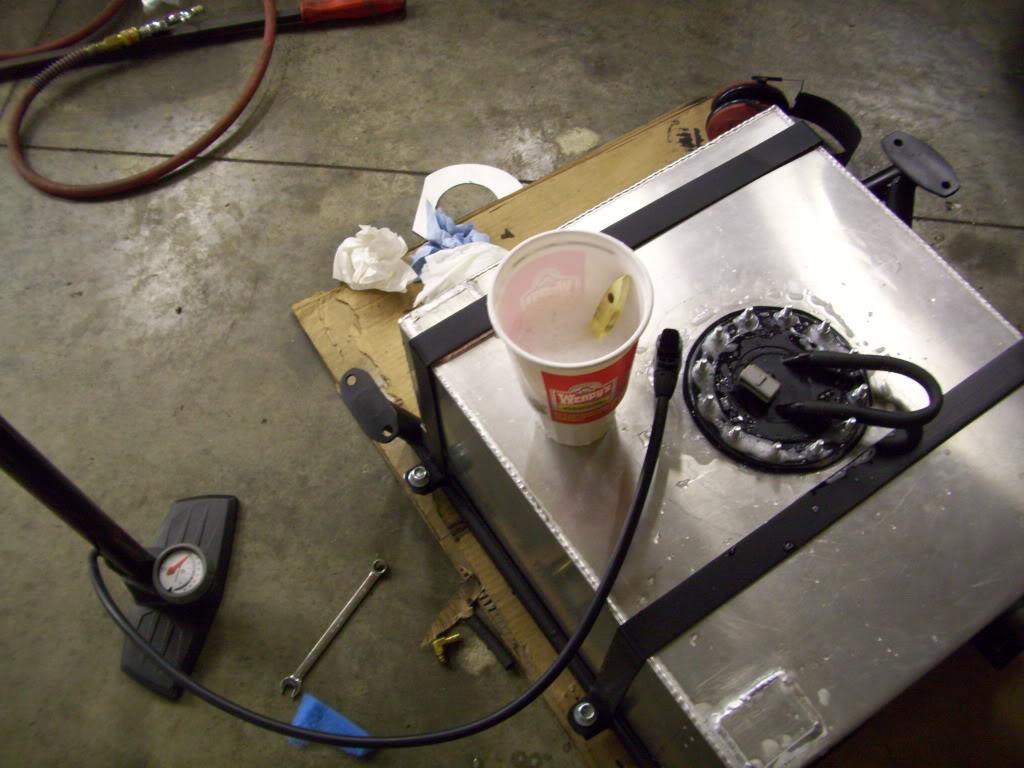
Good thing I left this sticker on there!

Ready for assembly into the car!
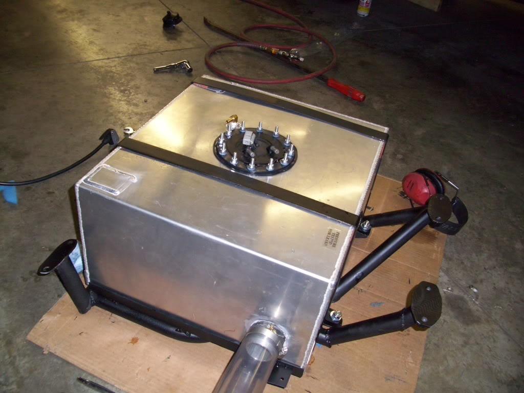
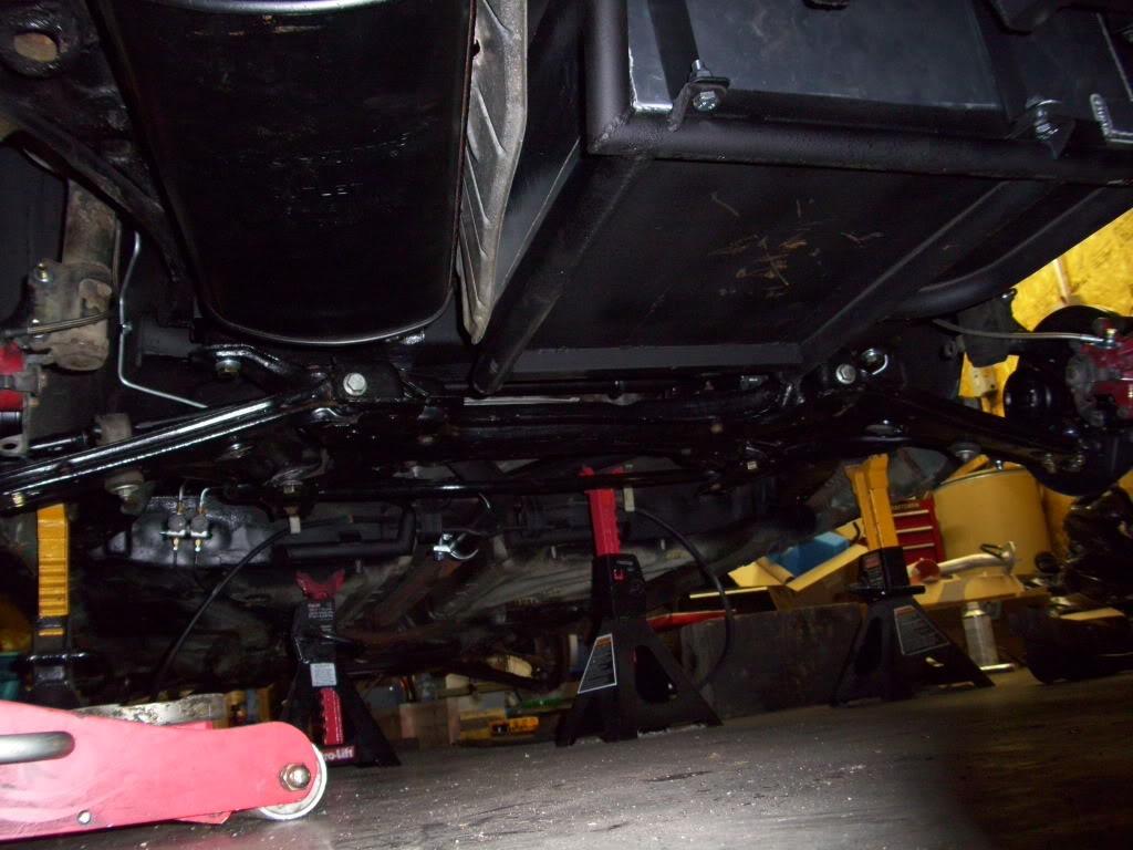
All in
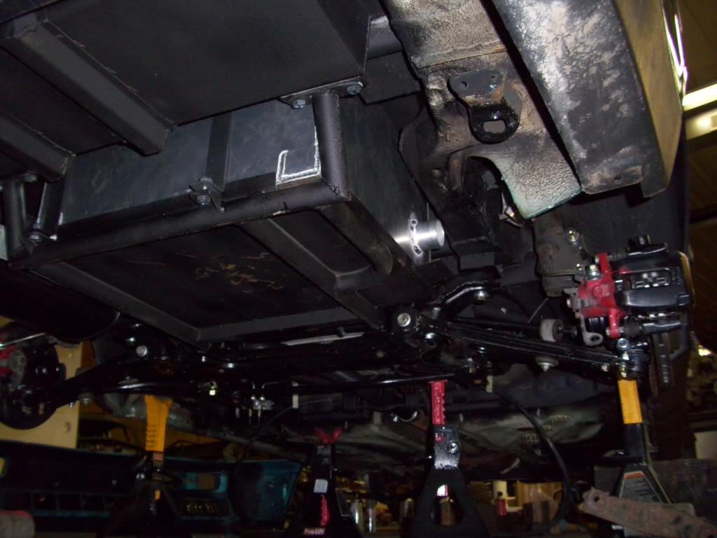
Notice the heat shield tape on the muffler side, as well as the modified stock heat shield around the muffler
Wiring passes through the body. This will get a grommet and gasket later on.
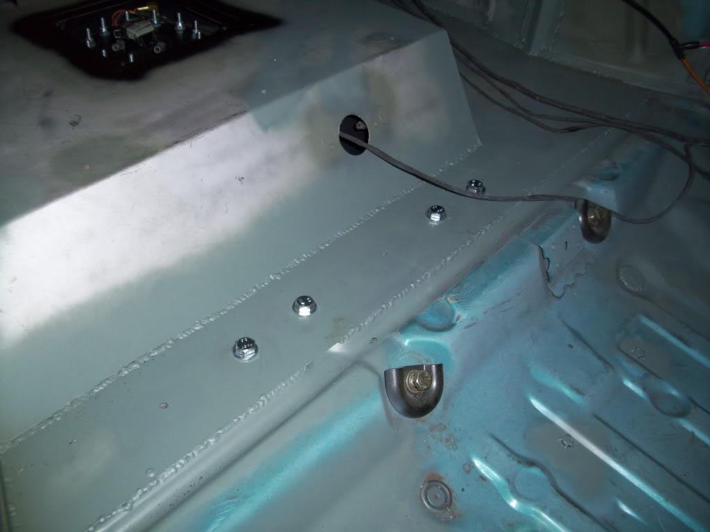
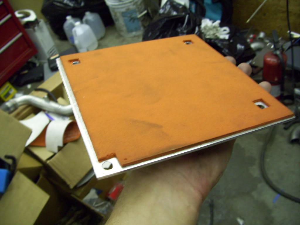
I made a gasket for the bottom of the fuel pump access panel in the floor, to keep it from vibrating and to seal it from the elements.
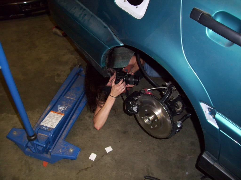
My friend Nicole came over with her fancy camera to get some decent pictures, since I suck behind the camera. She didn't f*ck around and got right up in there!
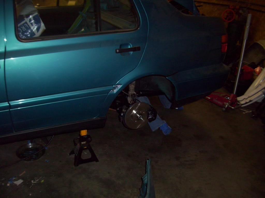
Here are some of her shots, unedited.
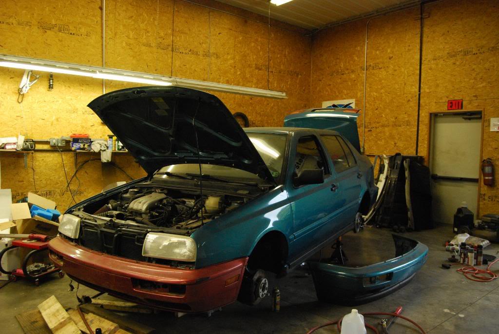
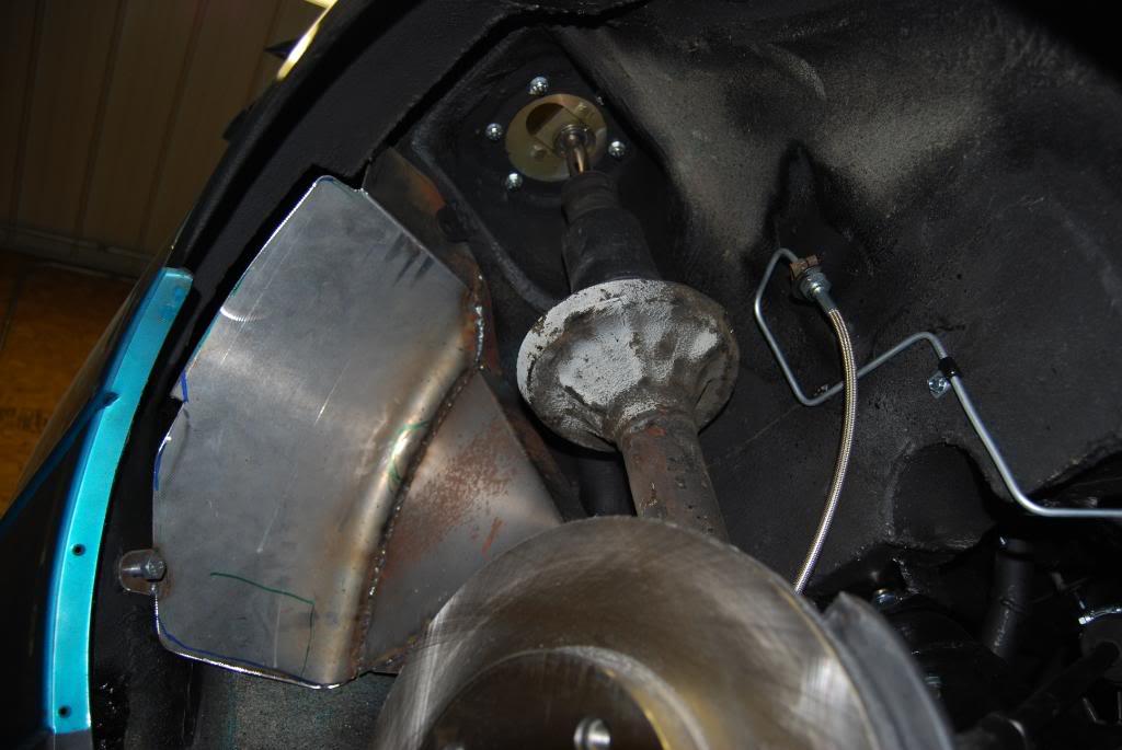
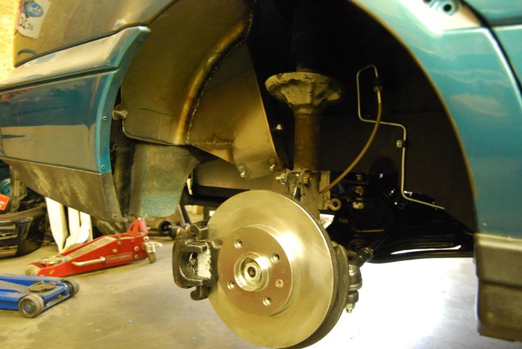
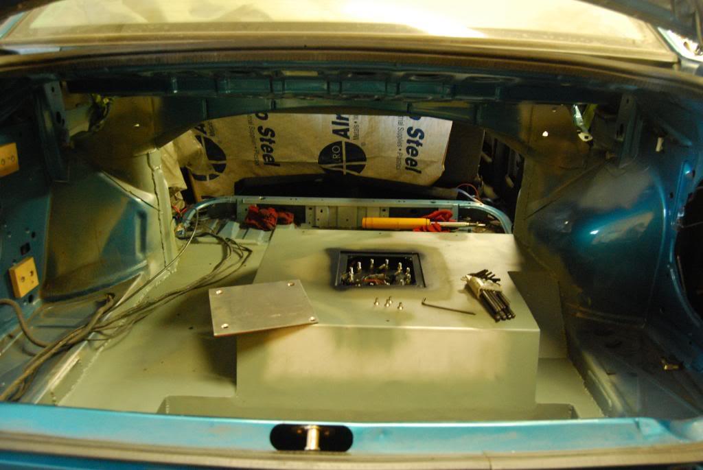
I was too busy to slow down and let her take pics apparently lol
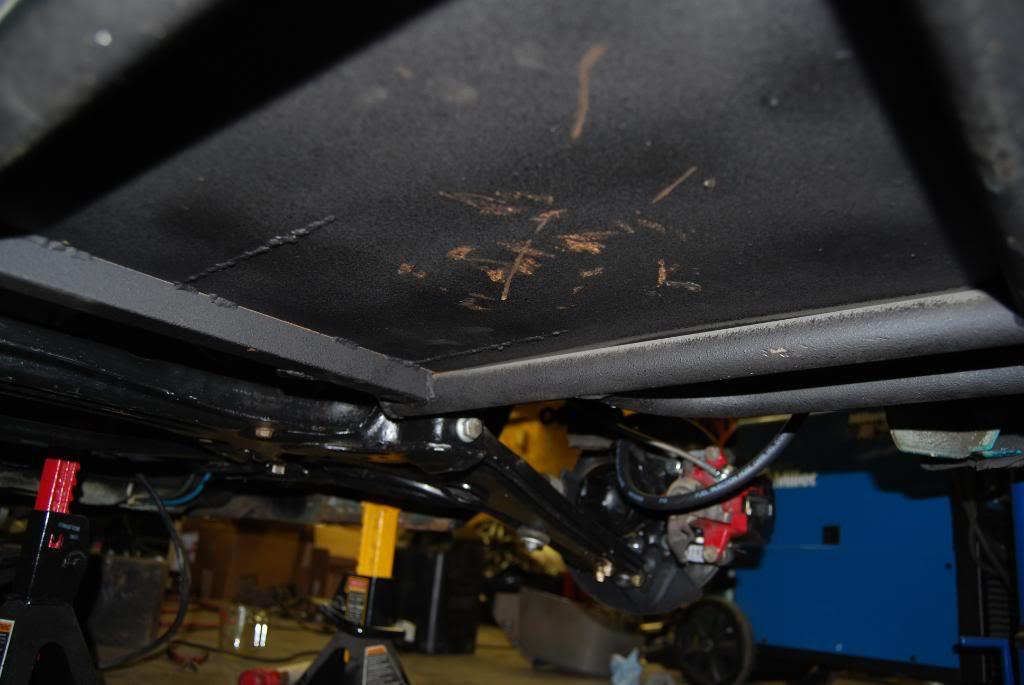
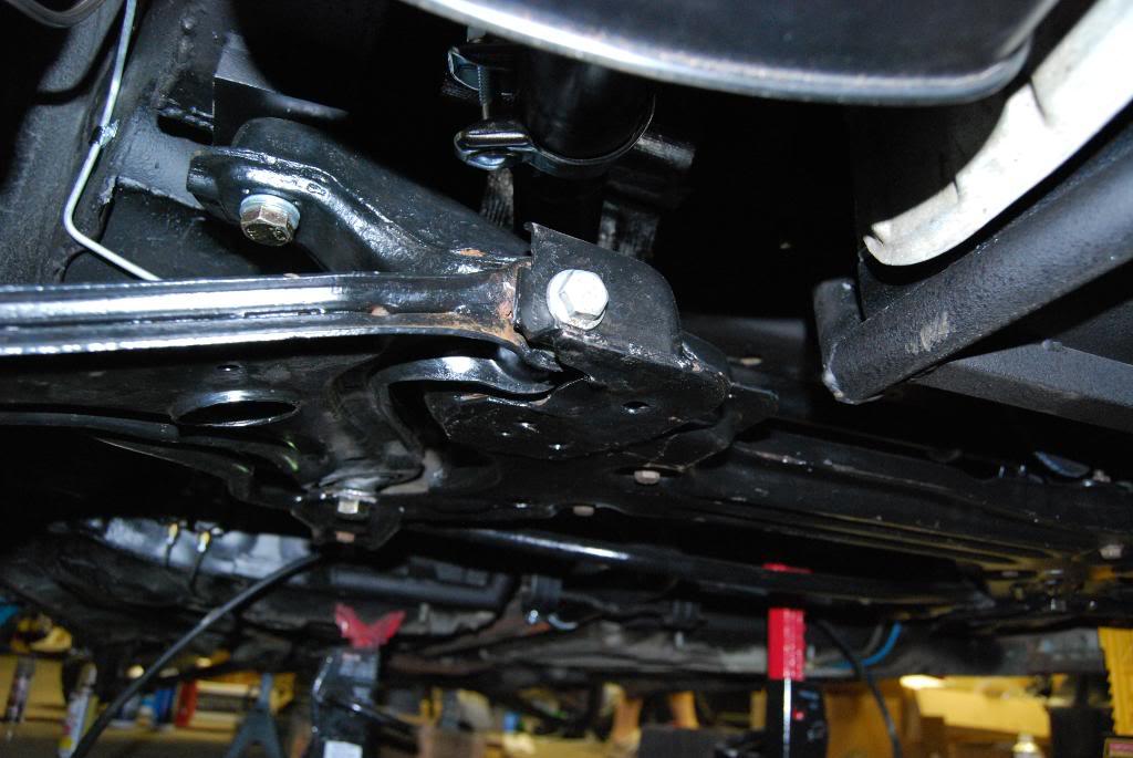
She was messing with the camera settings in a few of these, Nicole I'm sorry if I posted a "bad" one but they all looked great to me!
August 24, 2009
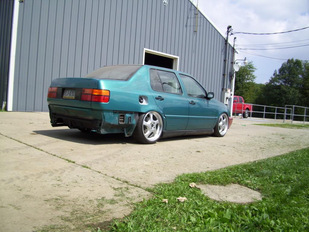
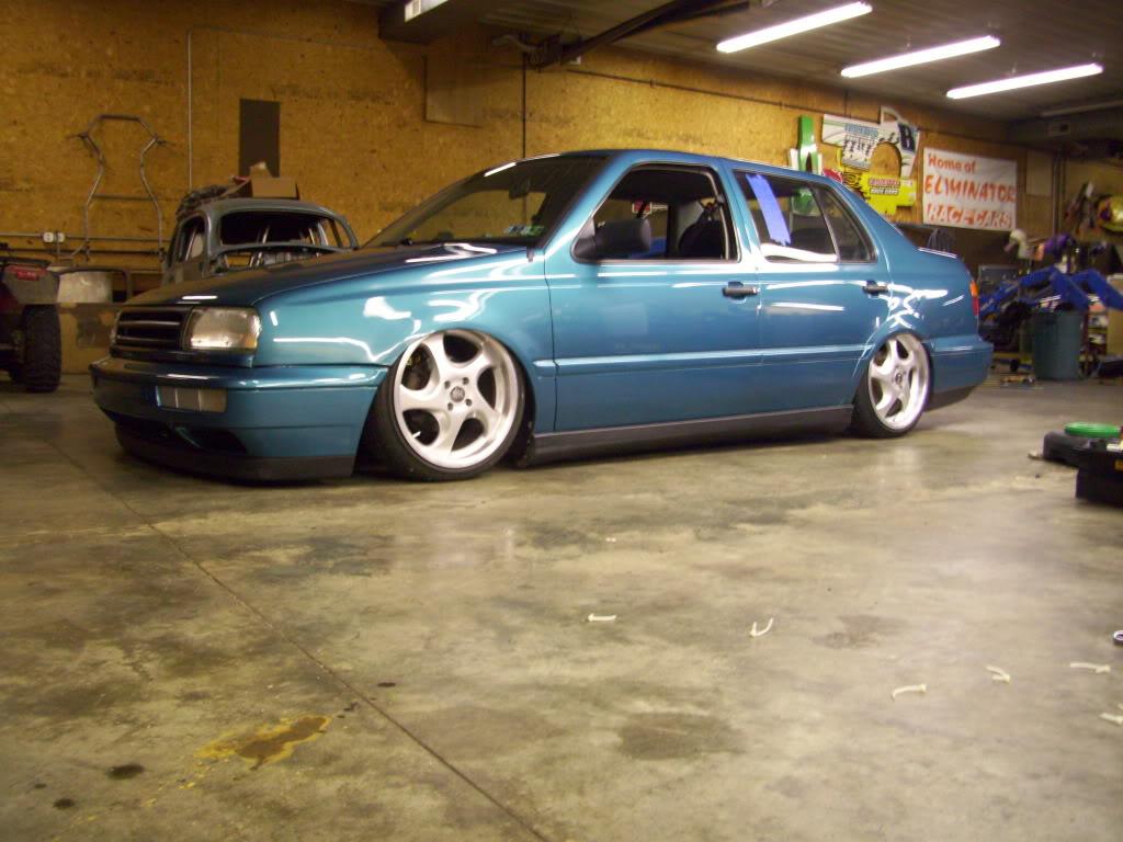
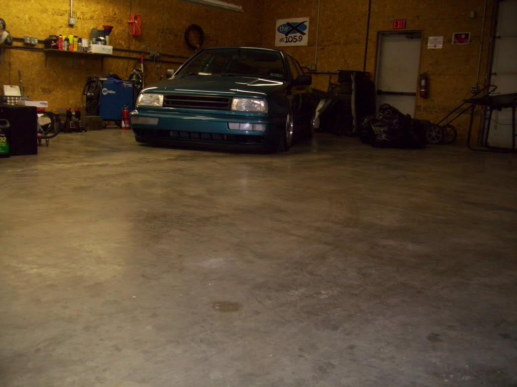
I took the day off work to get some work done on the car. I got everything all buttoned up and drove it outside!! It ran under its own power; started right up and everything worked! This is on 4 stock front struts, all blown out, and bumpstops stacked up to get it off the ground enough to roll. I took this opportunity to wash off the 8 months of garage dust and grime that had accumulated, it was really dirty! I was super excited to see the thing roll under its own power. It hadn't left the same corner of the garage since January!
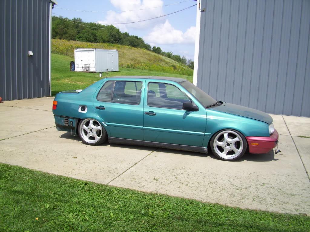
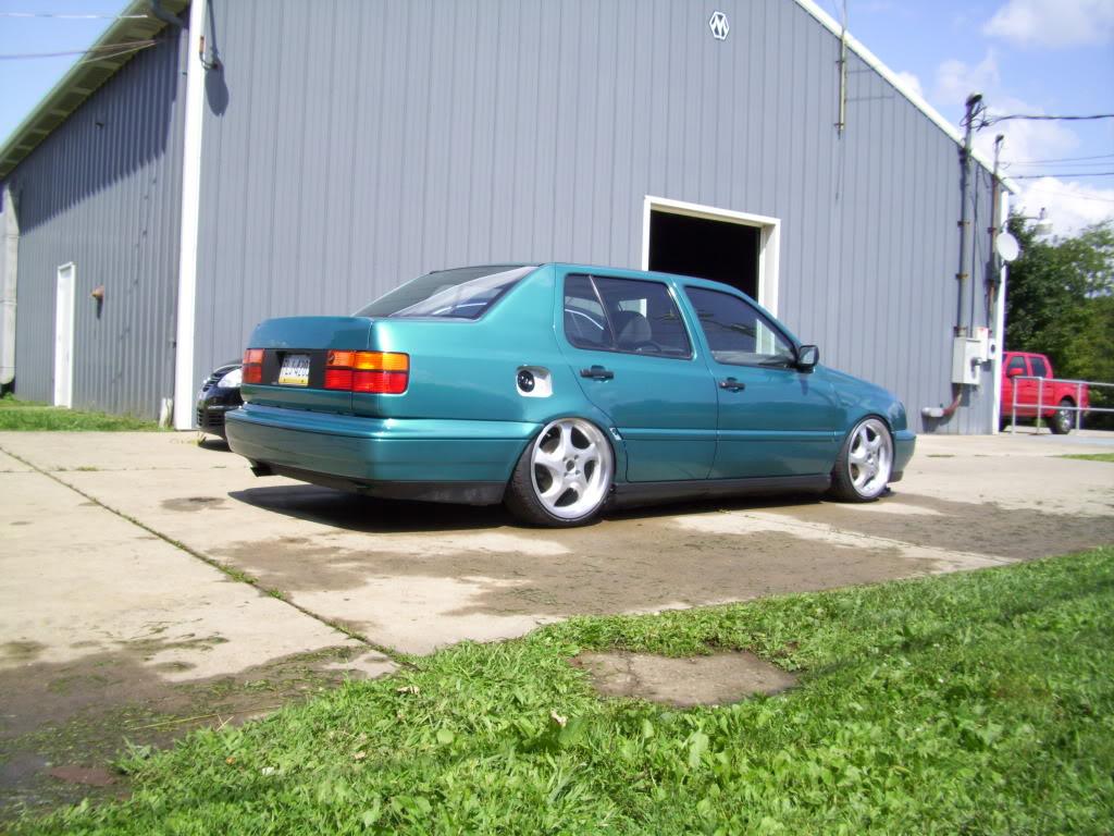
Cleaned up my mess while the car was basking in the sun
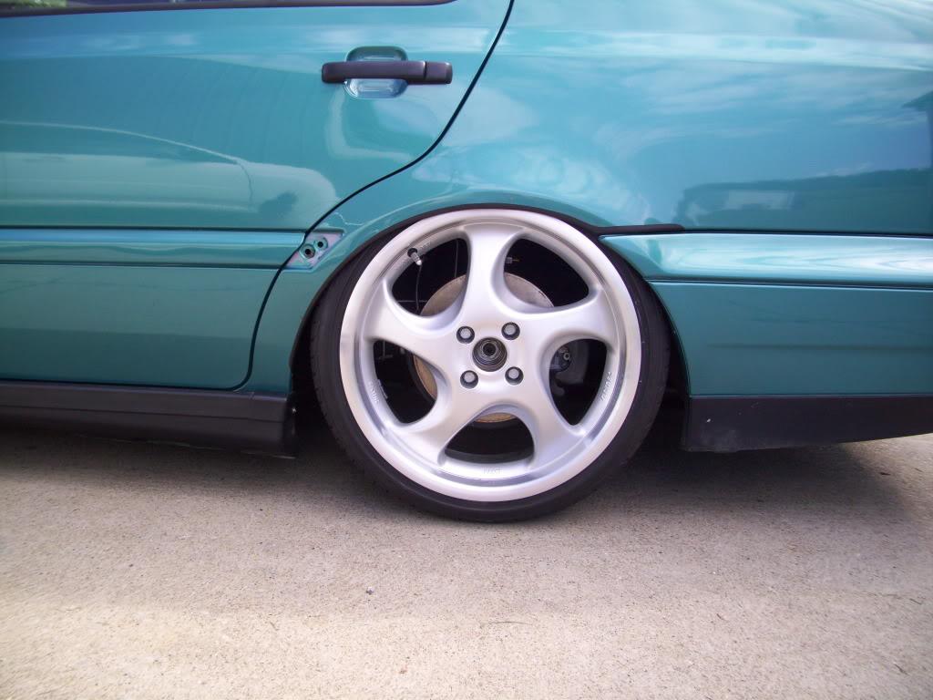
All sorts of camber to get it to roll
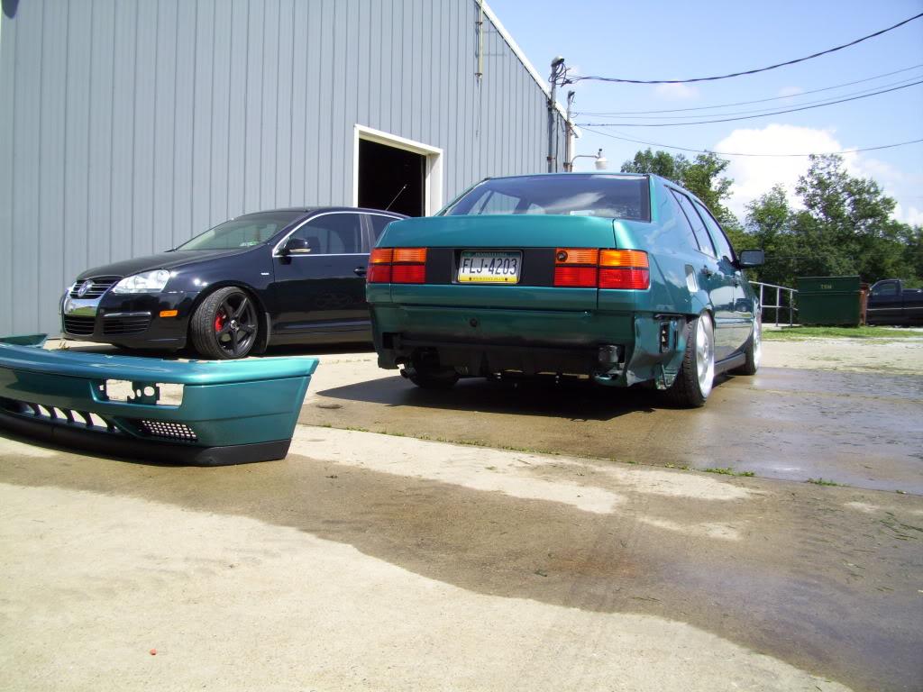
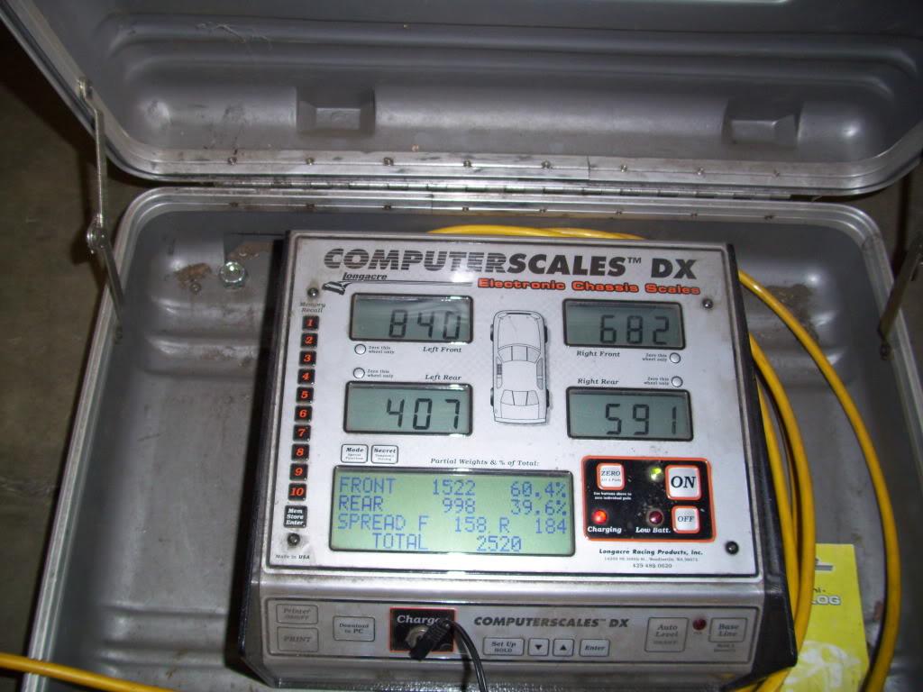
I got the car up on scales so I had an idea of what springs I wanted to order. This is without hydraulic pumps, 5gal of gas, no back seats, partial interior. That stuff all weighs about 150lb maybe? mostly over the rear wheels too. I haven't scaled it since the car was done.
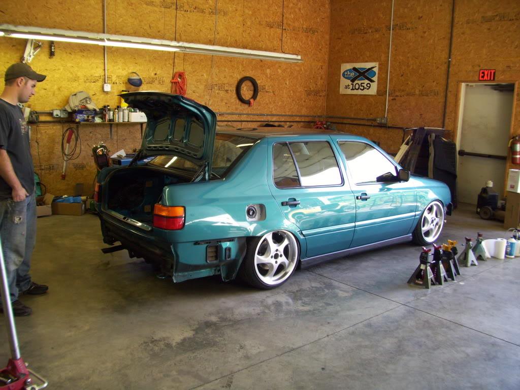
Woody (good buddy and TIG welder) looks on; the beast is back in its cage for the evening.
That's all the updates for tonight, I'm super tired and need to get to sleep. I'm away most of the weekend, but might get some updates in Saturday or Sunday evening. I will explain the hydraulic stuff I promise!
August 27, 2009
Less than one month to go!!!
Time to make the final decision about how this would be plumbed up.
The pump is a standard lowrider pump, I bought it from http://www.hydroholics.net. I dealt almost exclusively with Derek, and he was very patient and helpful since my application was very different from the usual hydraulic setup. For anyone that's seen this before, it's a #9 Rockford gear, aluminum manifold (3/8" ports) and chrome motor. The manifold has Delta dumps.
The manifold is also from Hydroholics. It's a 5-dump manifold. "Dump" is lowrider lingo for a valve. This manifold allows individual control of each corner of the car, provided that you have enough switches wired in. I only plan to run two switches - front and rear. But with the 5-dump manifold, if I'm driving at an intermediate height, fluid will not transfer between corners while turning or braking or accelerating. I decided this was the best setup for what I was doing, although even at this point I wasn't sure if the pump would be strong enough for my custom pistons!
I had a few options for the layout of the pump and manifold - the two major components. I tried this first:
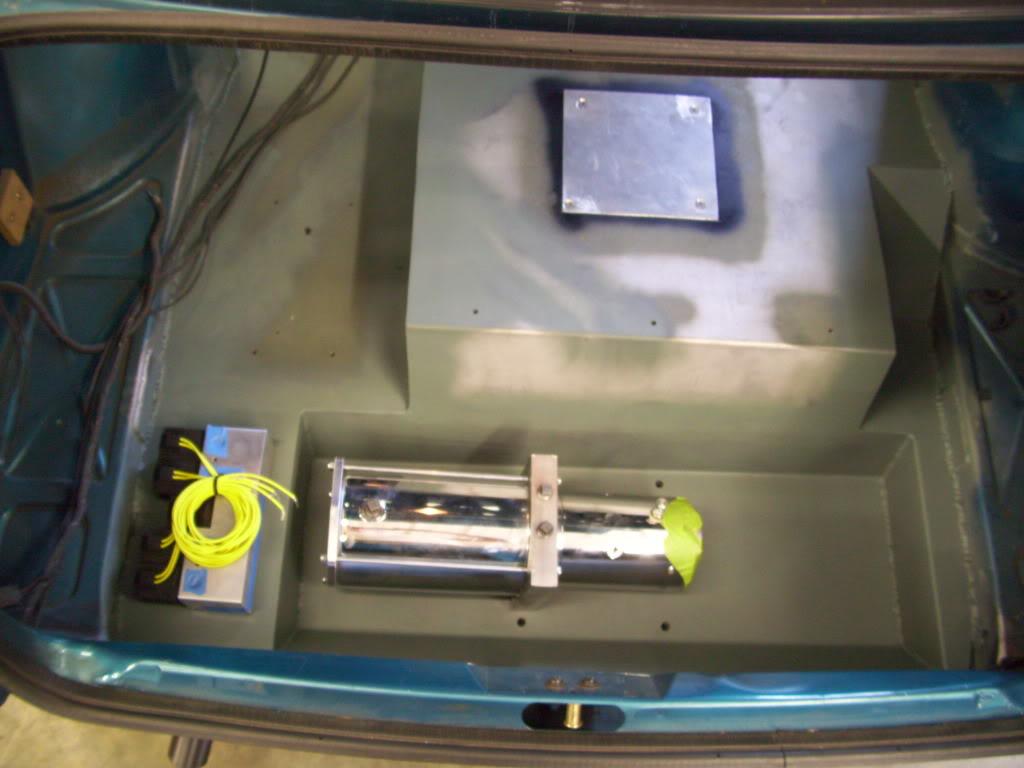
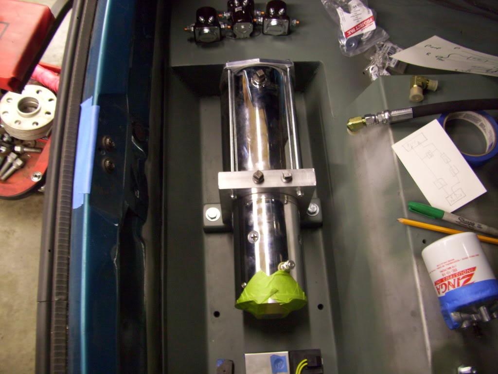
I didn't like that setup. Then I tried this, and decided this is where I wanted everything. The fluid lines for each corner would come out the bottom of the manifold on the bottom of the floor, and would be pretty well protected by the fuel cell cradle.
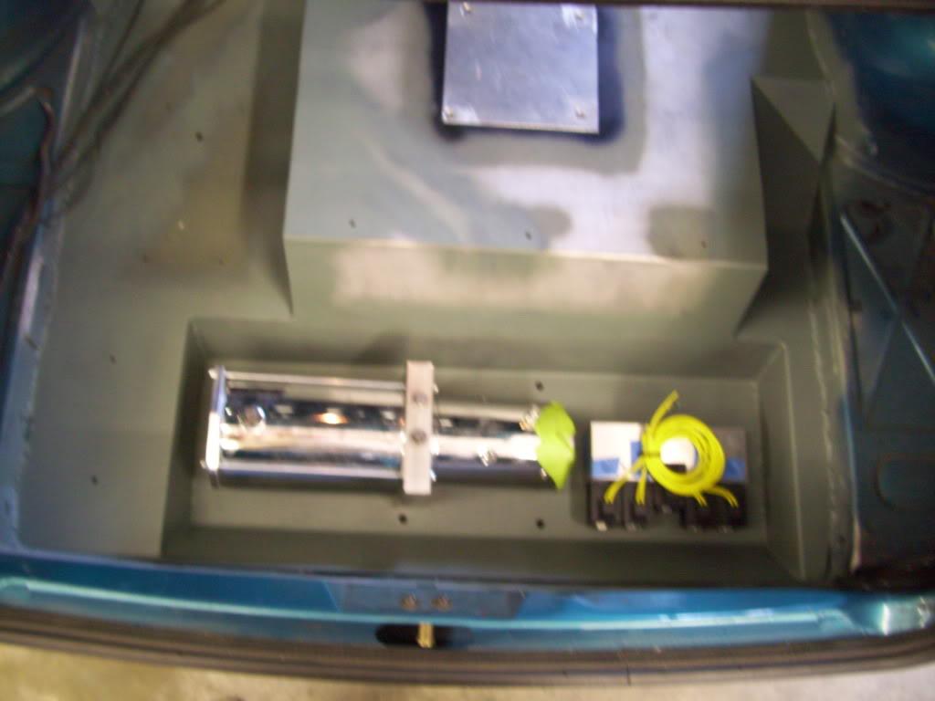
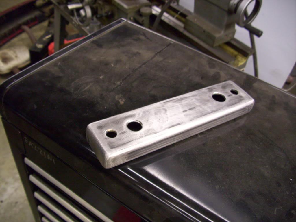
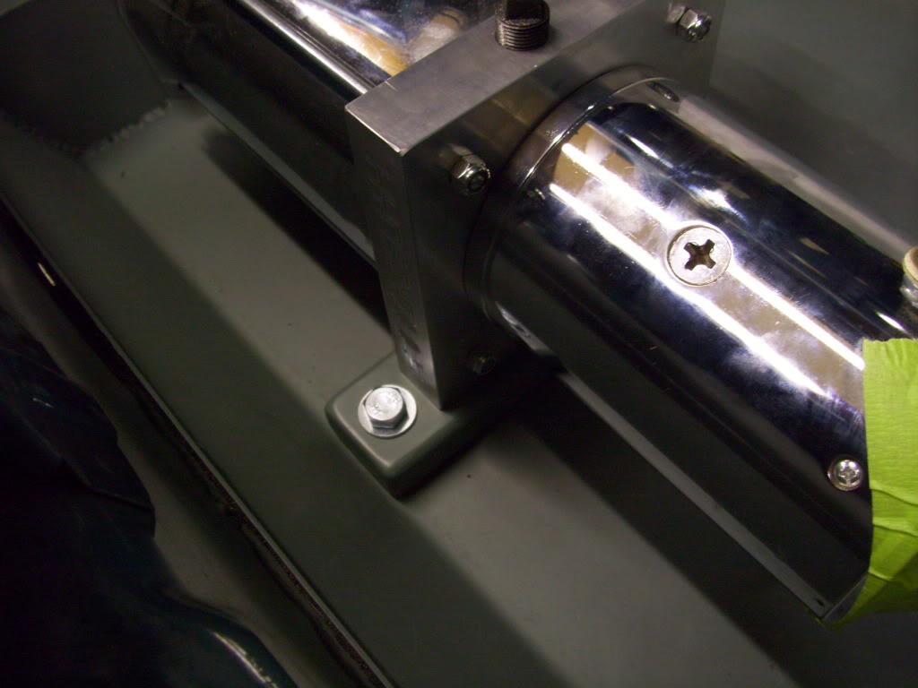
I made this bracket from 1/8" steel to mount the pump to the threaded inserts that were welded in the floor a few weeks prior. The pump bolts to this bracket, then the pump/bracket bolt down to the floor.
Top view:
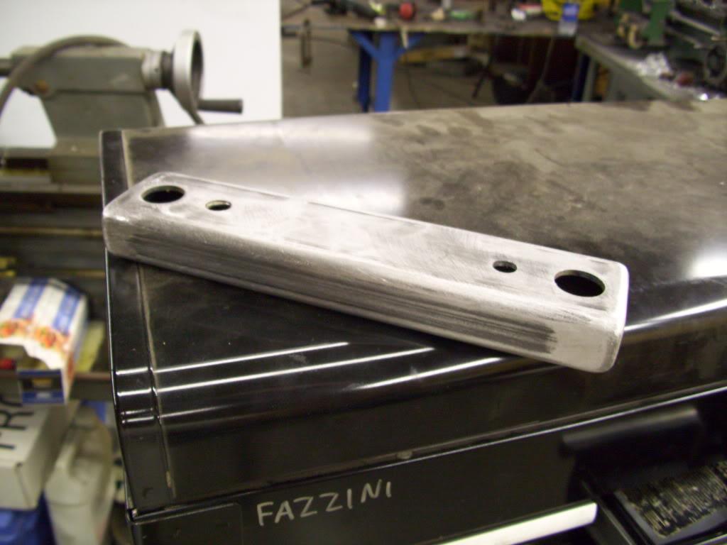
Bottom view:
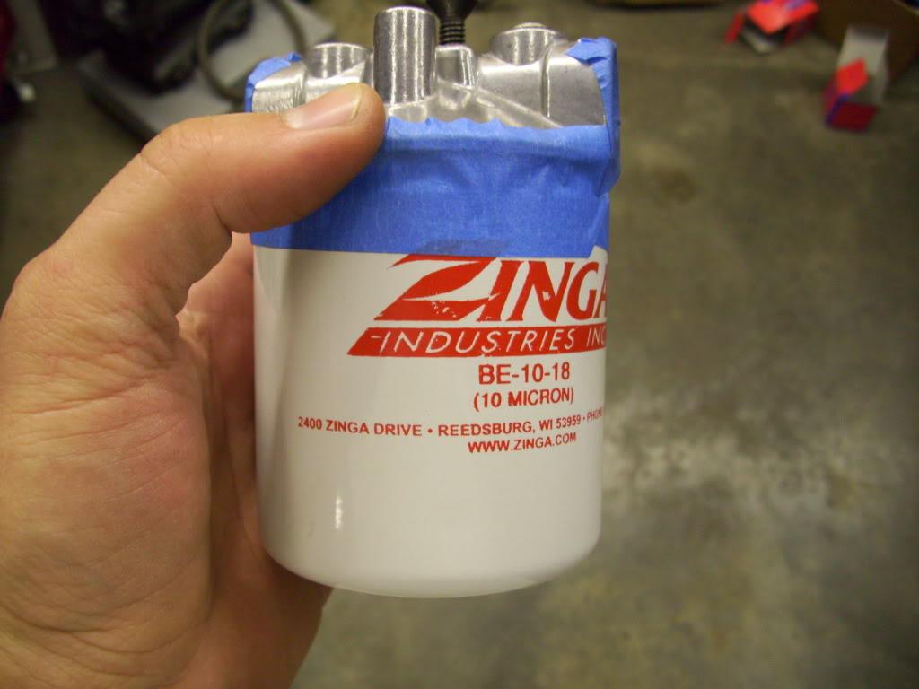
I decided to run a filter on the return line, just to filter out any crap that gets into the lines or metal particles that wear off of the pistons.
I made this aluminum plate to mount the manifold to, then I could bolt the plate down to the floor.
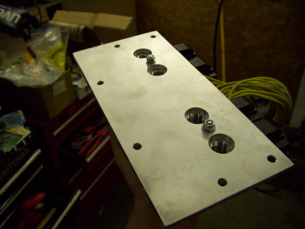
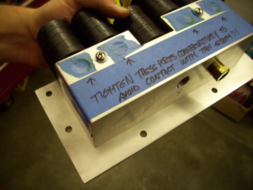
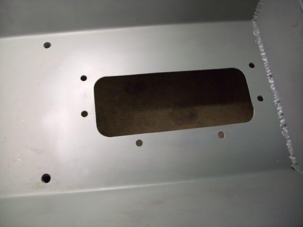
I cut a hole through the floor to mount the manifold plate
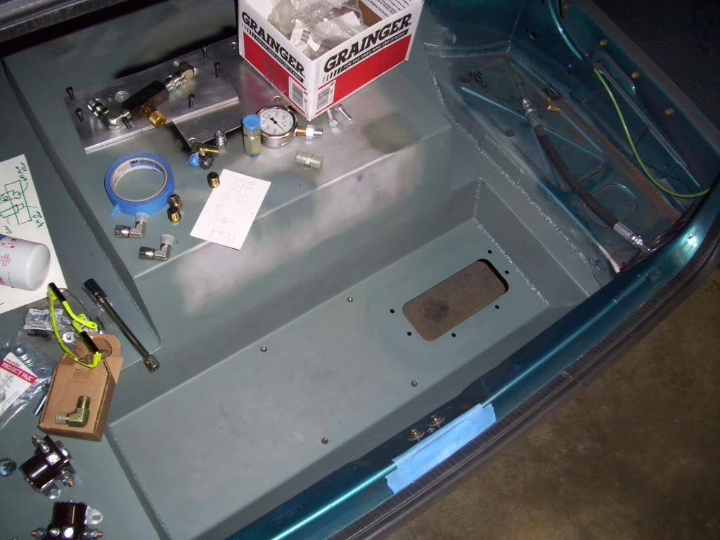
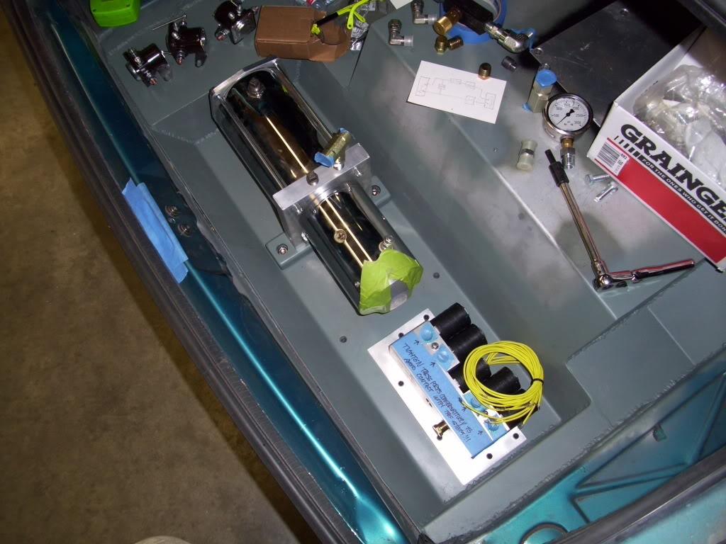
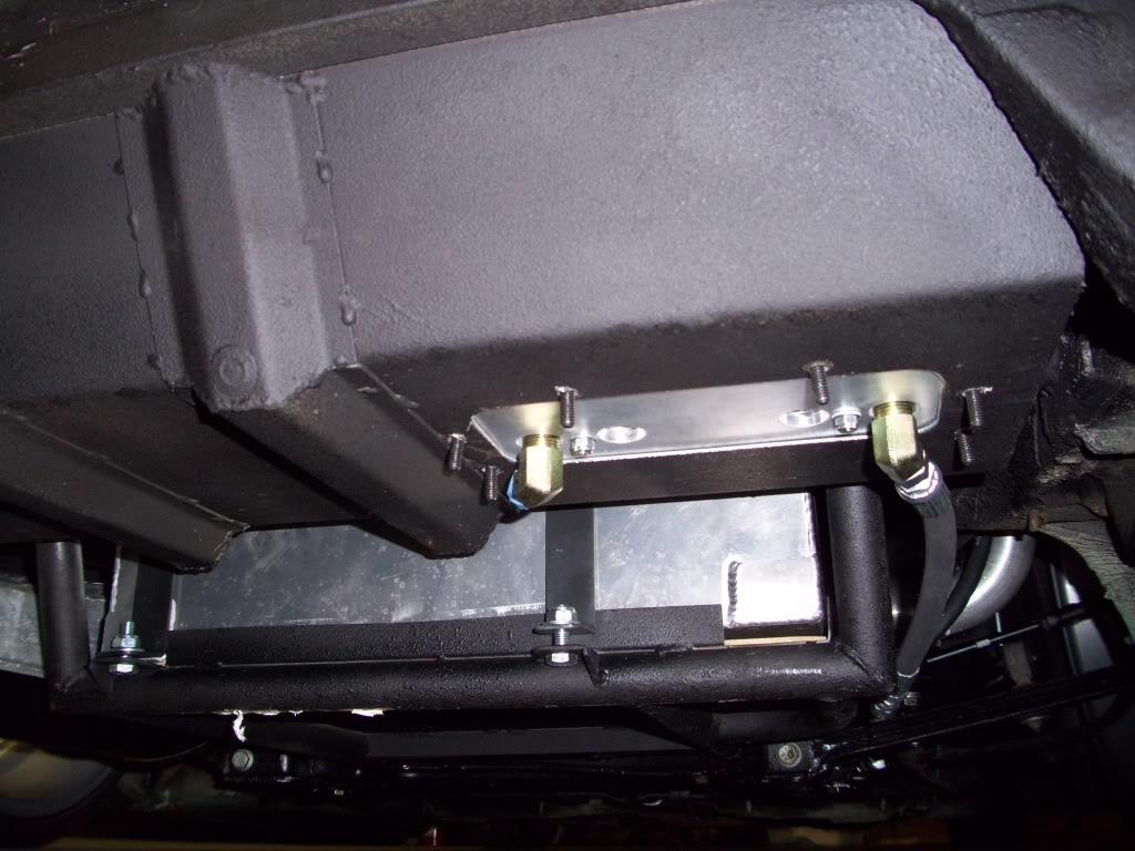
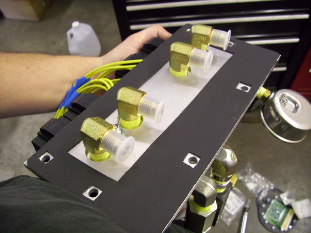
Here is where the hoses will come out the bottom of the car. Each of the 4 fittings will send fluid to each corner.
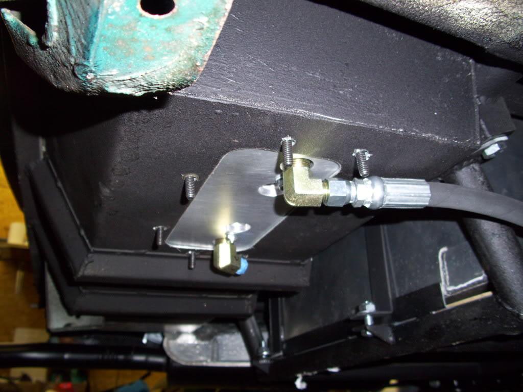
Here's a view from the rear of the car, you can see the hoses are a few inches above the fuel cell cradle so it's pretty well protected.
August 30, 2009
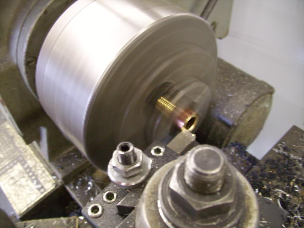
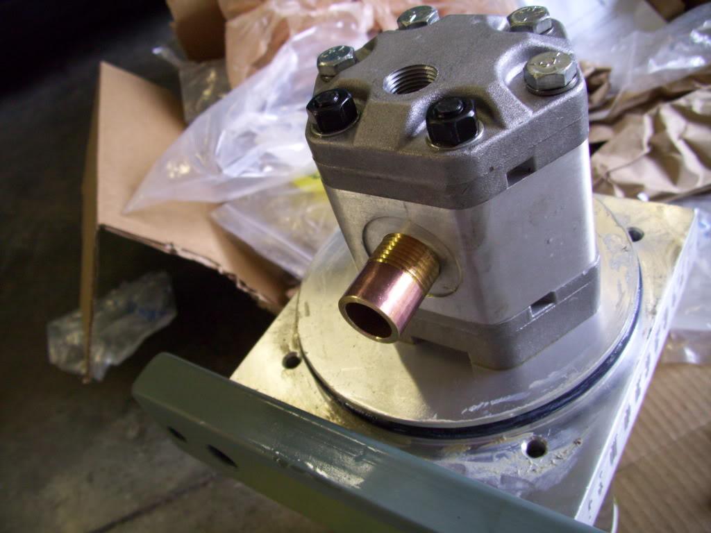
I machined a new pickup tube for the pumphead. Because I'm mounting the hydraulic pump at a different angle than the standard Hydroholics method, I had to make a new pickup tube to pull oil from the bottom of the tank. With these pumps the pumphead itself is inside the fluid reservior, then the motor is on the opposite side of the "block" (large plate between the reservior and motor.
Turned down a brass nipple
Here is the pumphead mounted to the block with the fluid reservior removed. You can't see the motor, it's on the other side.
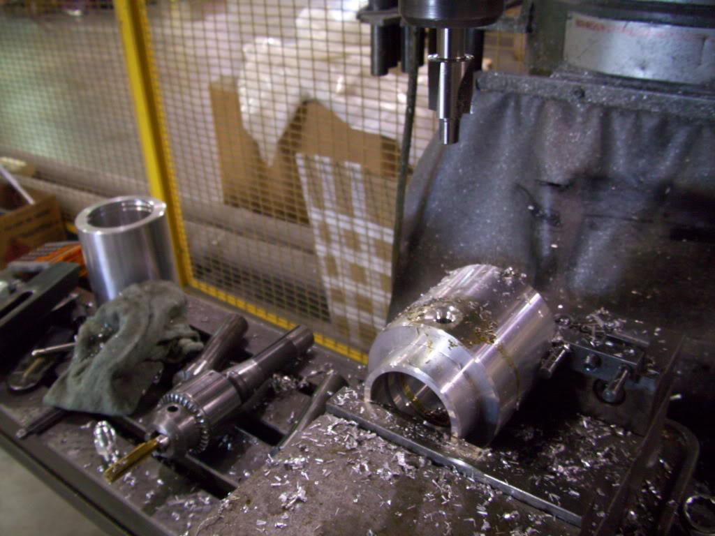
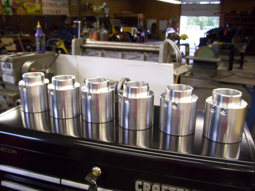
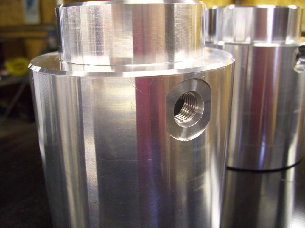
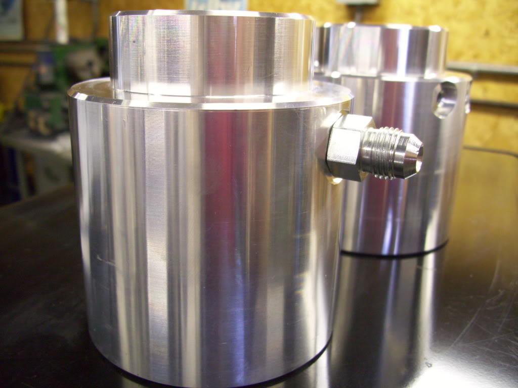
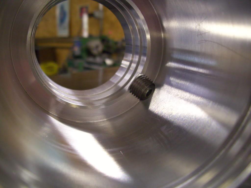
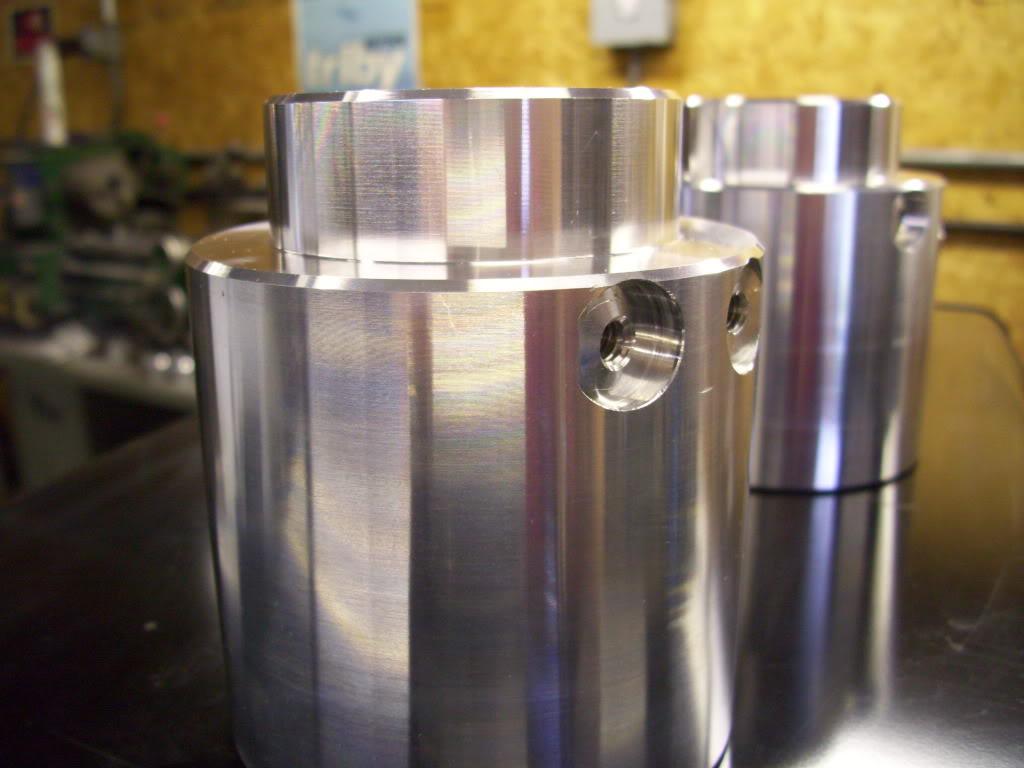
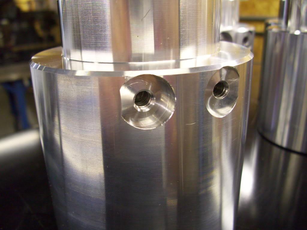
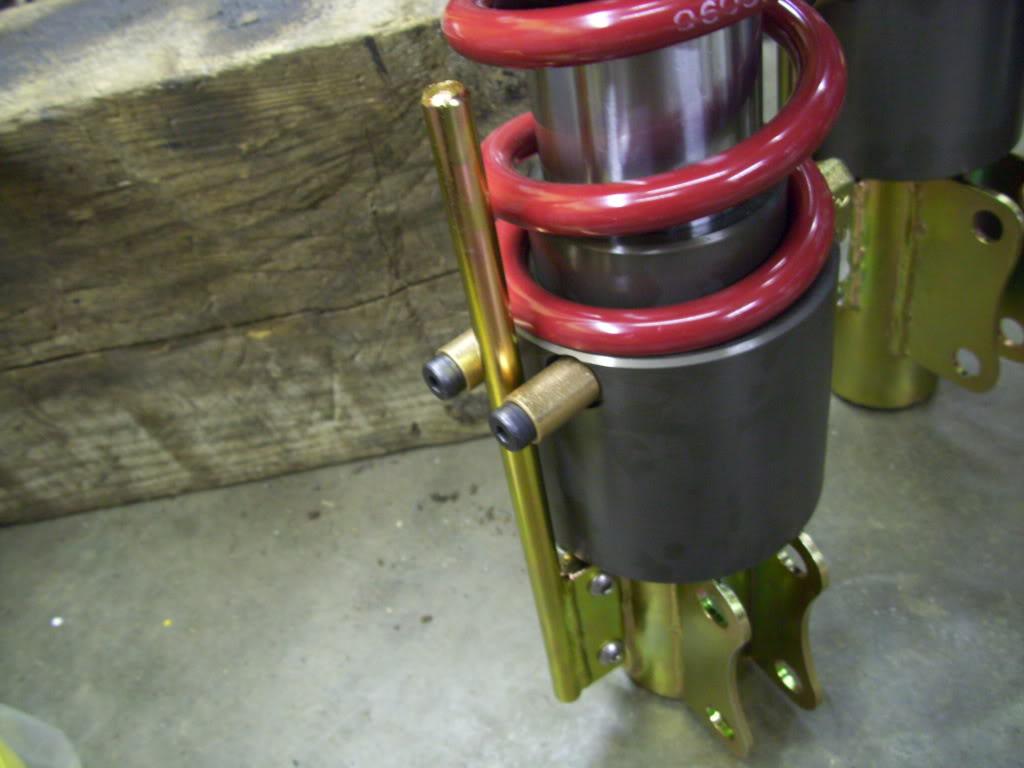
I still had to drill the fitting port holes in the side of my pistons. This is the fluid inlet for the hydraulic pistons which will mount on each strut. I have 4 plus two spares for a total of 6 pistons. The fitting is a -4 SAE O-Ring Boss, which seals using an o-ring. They're reuseable, consistent, not subject to thermal cycling, hold more pressure than I will ever need. Much better than NPT in the high pressure hydraulic world!!
I borrowed some time on a milling machine and did this part myself. I also had to drill two holes at the back of the pistons for anti-rotation pins which will keep the piston from rotating and prevent the fitting from rotating into the tire. Again, more on the hydraulics later.
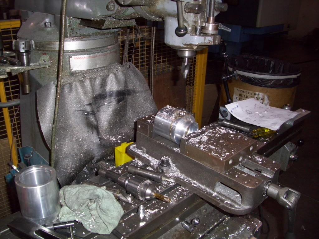
All finished!
Here is the fitting hole:
Here is the fitting installed:
Here is the inside of the piston:
Here are the two tapped holes I made for mounting the anti-rotation features. Again I will fully explain this later, but two pins will be screwed into here which will ride on a pin to prevent the piston from rotating on the strut.
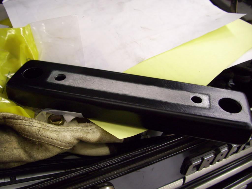
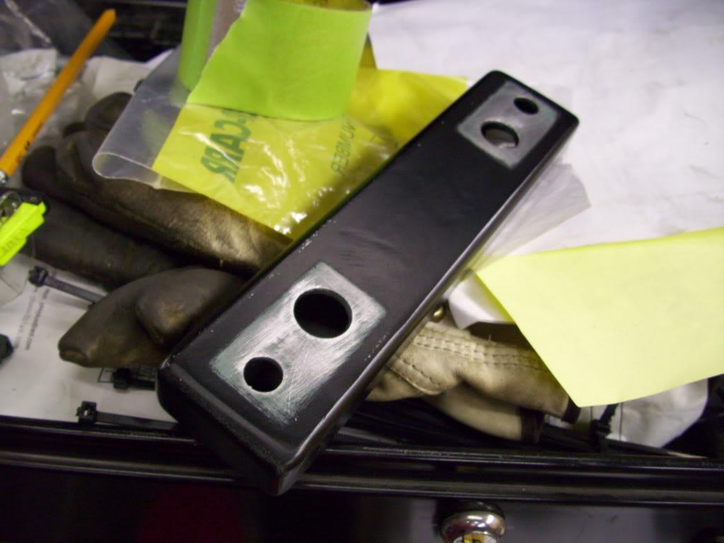
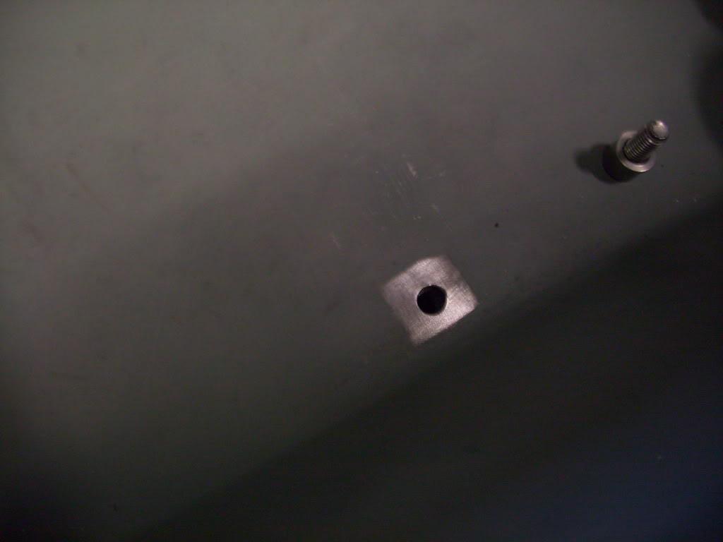
Because the hydraulic motor grounds through the housing, you need to ground the bracket that mounts it to the chassis. There is only one hookup on the motor: 12v power. I painted the bracket and removed the paint on the bracket and on the trunk floor for better contact:
Then I started plumbing up the setup. I used all zinc plated steel hydraulic fittings, either 3/8" NPT or -6 JIC flare. I used yellow Teflon "gas tape" to seal the NPT threads.
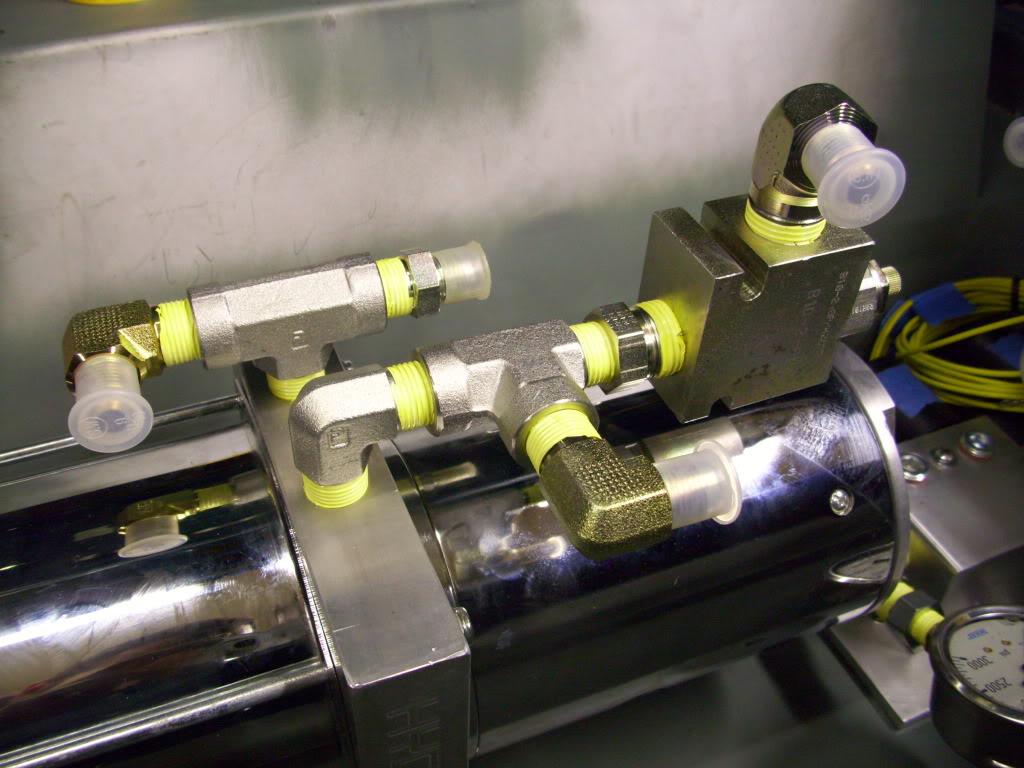
This thing here is a pressure relieving regulator. When pressure exceeds the preset value, it bleeds fluid back into the reservior. This is helpful because I can just hold the "up" switch down until the car tops out, then the valve will open and excess fluid will just dump back into the tank until I let off the switch. It's adjustable from 500psi all the way to 5000psi. I need about 400psi to lift the car, and have it set to 1000psi just for uneven surfaces and so it doesn't bleed off when it's lifting and the pressure spikes slightly
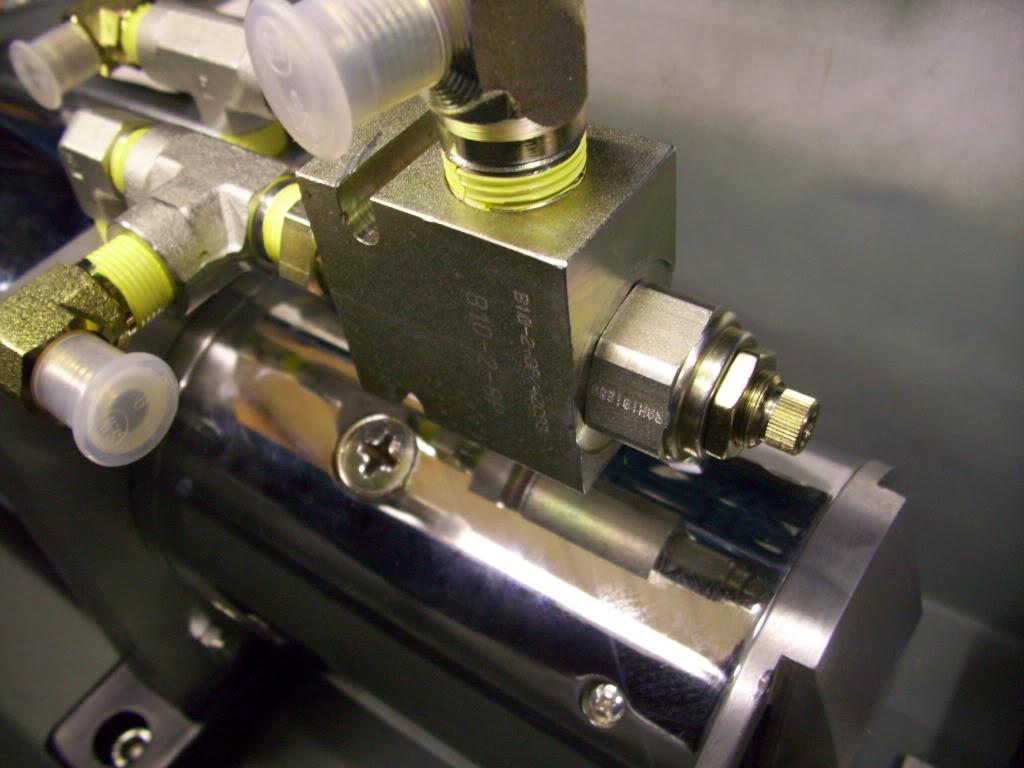
Here is the manifold:
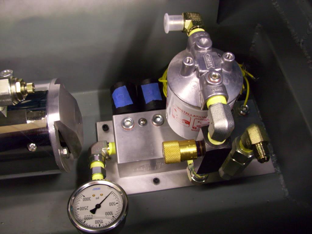
At the right side of the picture, that's the fluid inlet. It goes through a check valve to prevent fluid back-flow into the pump, then into the manifold. Coming out of the front center of the manifold is the return path. When I lower the car, fluid flows through the flow-control valve (adjustable for drop speed) then through the filter, then back into the reservior. The 3000psi gauge on the left is to for setting the pressure relief valve, and to aid in troubleshooting if I ever have any problems.
August 31, 2009
I got the fuel filler neck guard all cleaned and painted up
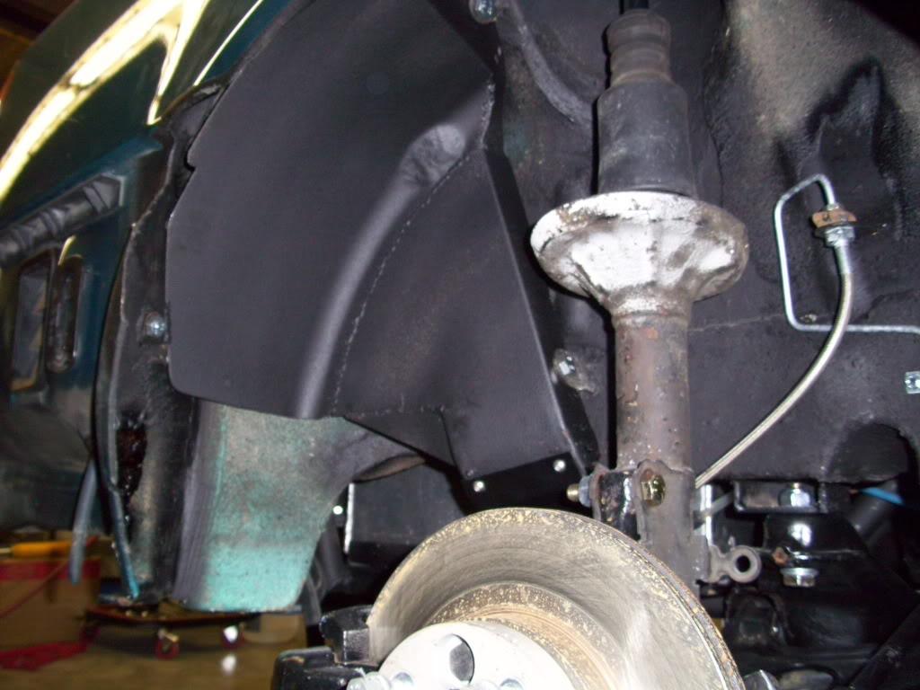
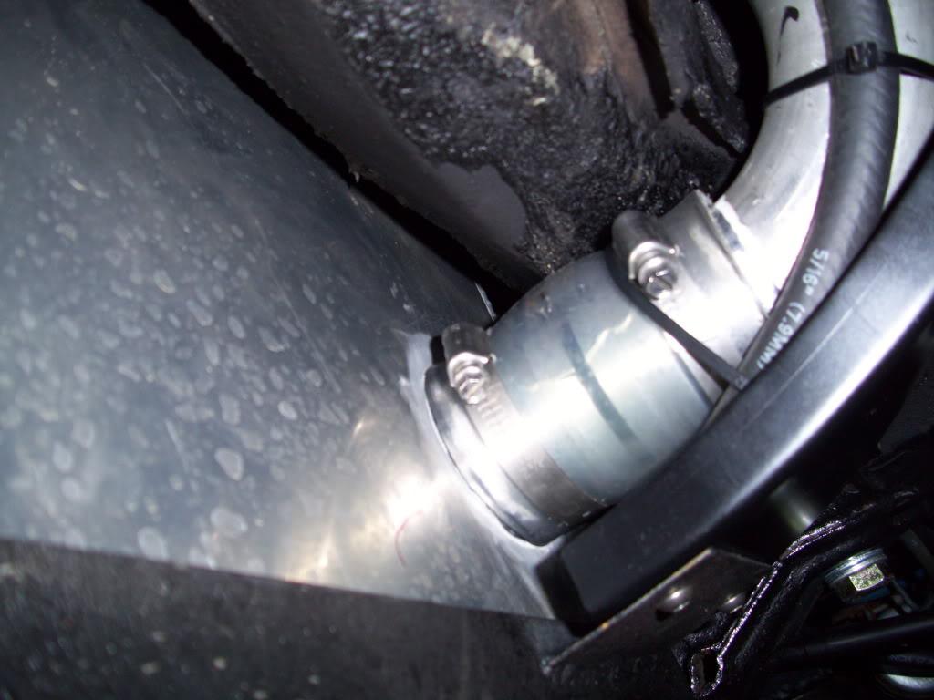
Here is the coupler for the fillerneck into the tank, I haven't pictured this before I don't think but it was done a few days prior.
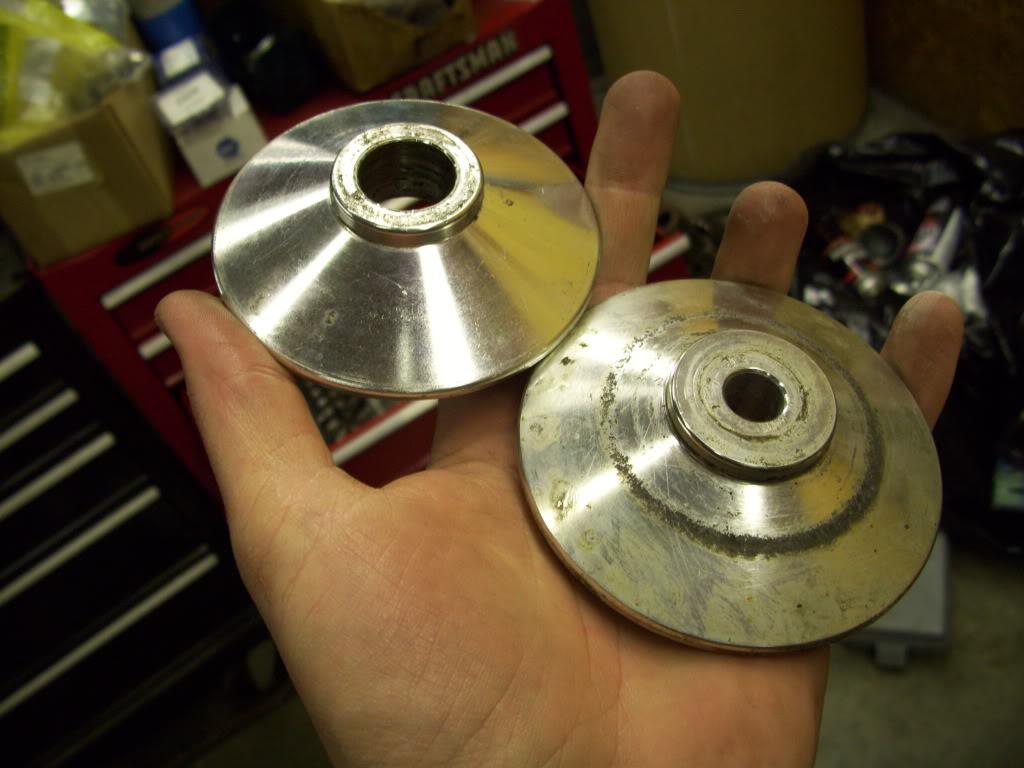
I found some spring seats from an old Ebay coilover kit that I can use for the rear upper spring seats. This saved some machining time!
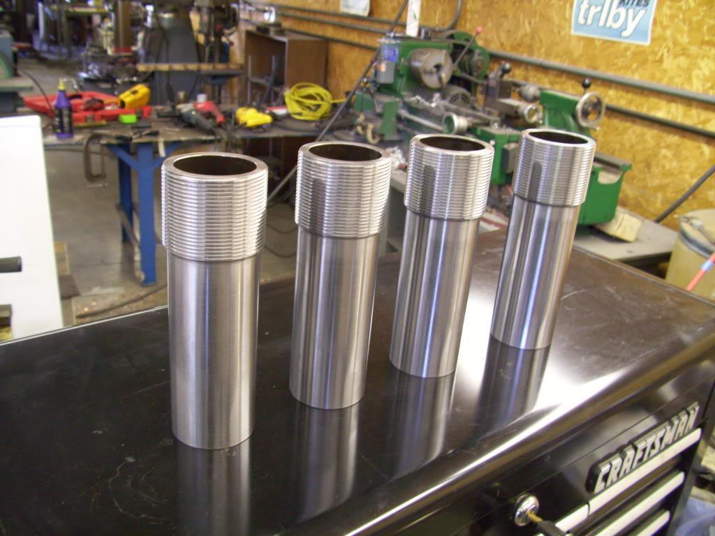
My friend Woody machined these for me. He's a damn good CNC lathe operator, and made a few of the parts for the suspension that I wasn't capable of making. He whipped these up - the lower half of the rear struts. This is the last machined part for the suspension that I won't be making!
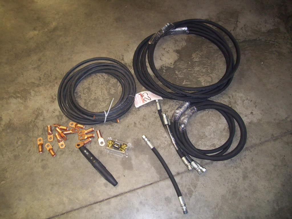
I had a chance to get all the hydraulic hoses made and buy the power wire and fuses and connectors for the whole hydraulic setup. The hoses are Goodyear GR16SC. 5,000psi working pressure, 20,000psi burst pressure. -6 JIC straight swivel ends. The power wire is 2/0 copper welding cable, 200A fuse.
I pulled off the manifold plate and made a rubber gasket for it to seal it from the elements.
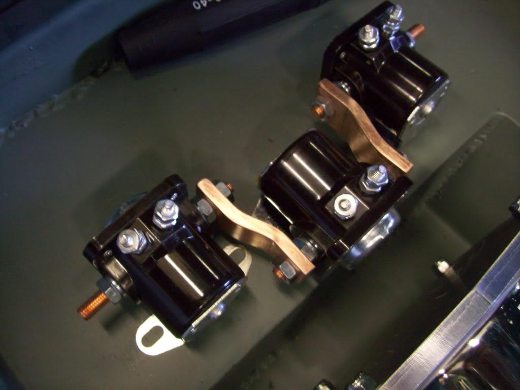
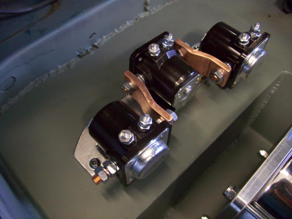
In order to switch the hydraulic motor on, you need to use a relay. Because the current is so high and the relays most lowrider guys use are undersized, they typically run several in series in case they weld closed. When you run one relay (called 'Solenoids') and it welds shut, the motor will stay running. If you run 3, you have to weld all 3 before you get a runaway motor, which is highly unlikely and reduces your chance of a problem.
I made these copper bars to connect them
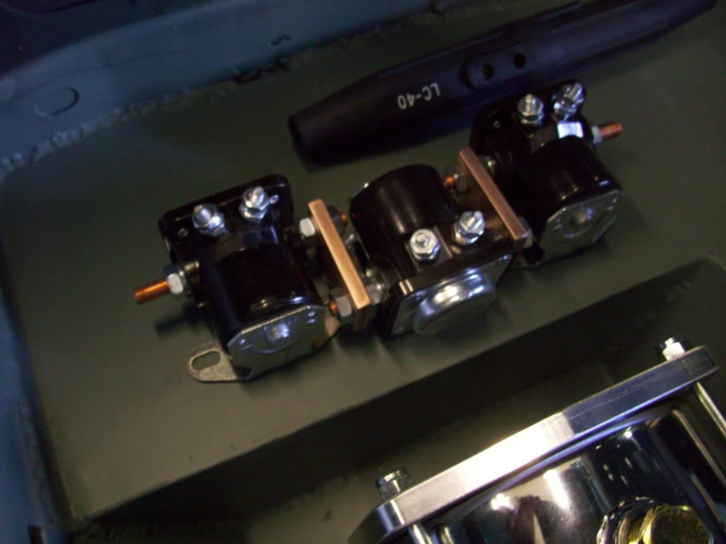
After looking, they were pretty close to the housings:
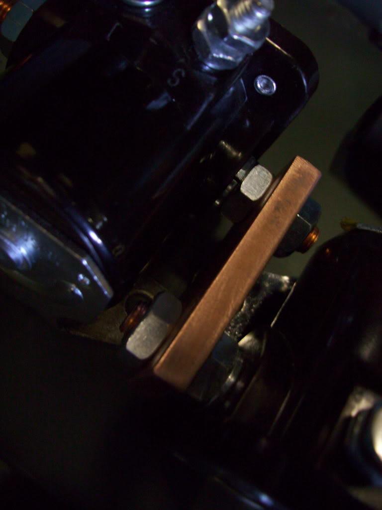
That's no good.
I remade the copper bars and added a little bend to space them apart, to eliminate the chance of arcing across to the housing of the next solenoid.
Then I made this aluminum bracket to mount them all onto.
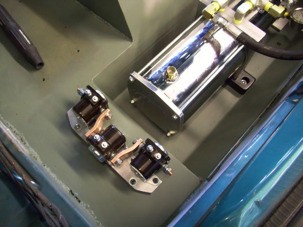
I got the hydraulic hose connections in the trunk all made. One hose from the pressure relief valve into the manifold, one return hose from the filter back to the tank, and one return valve from the relief valve back to the tank.
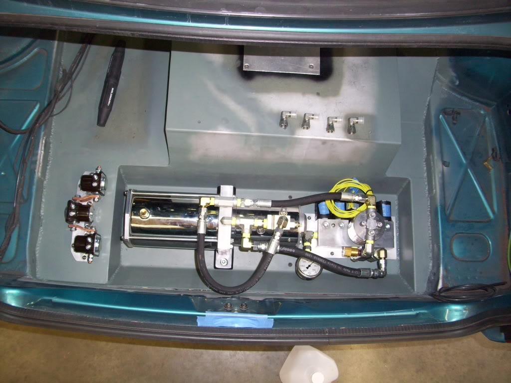
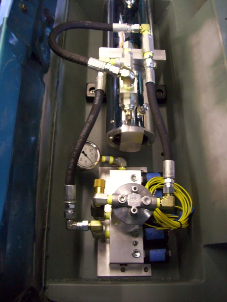
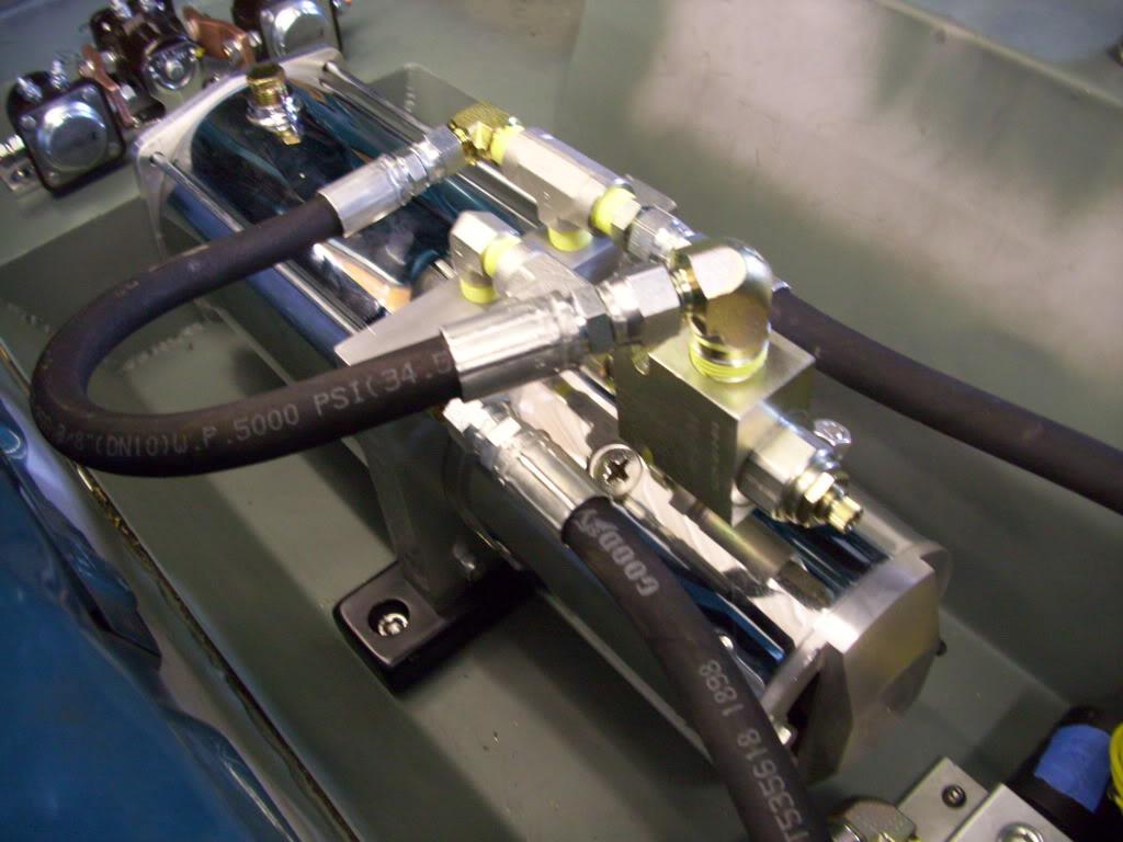
That concludes August 2009. More updates soon!
September 1, 2009
I got the Ground Control front drop-in camber plates. These things are very nice; incredible design, the build quality is great, the materials and components chosen... Very great product overall They're pricey at $350+ per pair, but well worth it. I will probably end up upgrading my rears to GC down the road sometime.
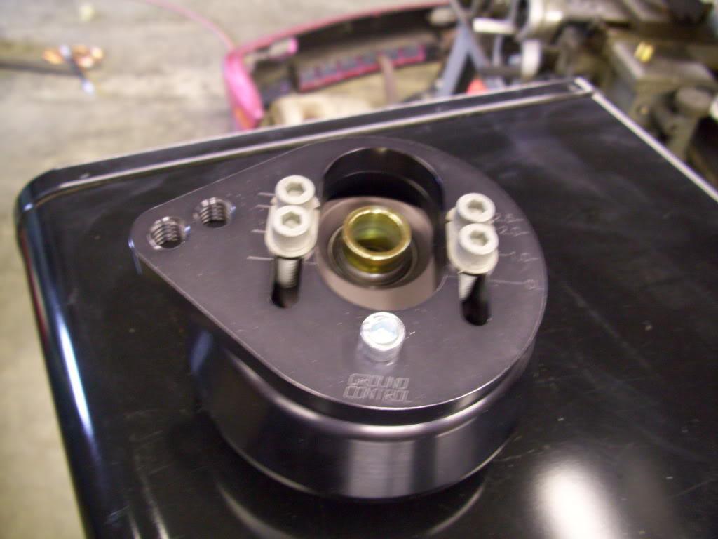
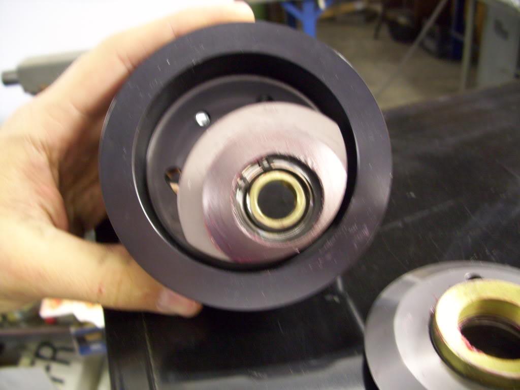
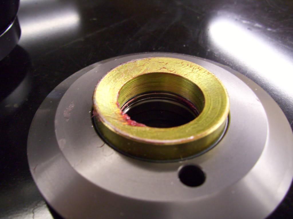
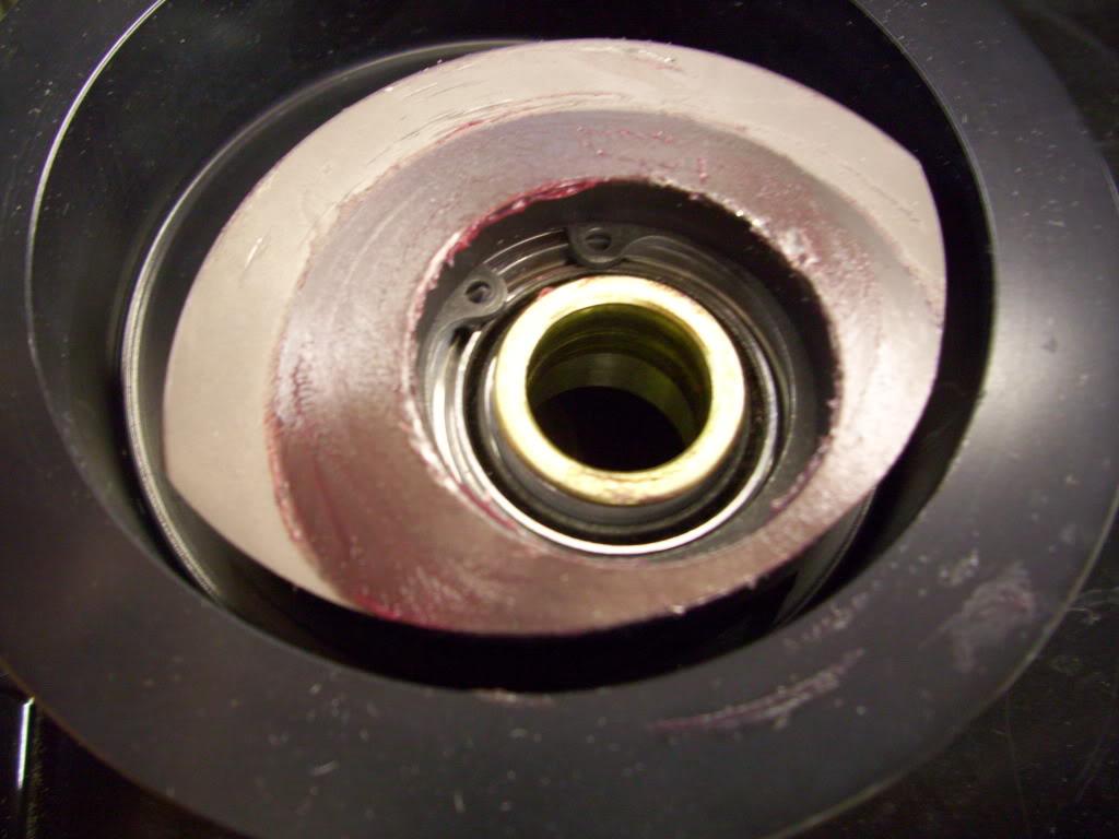
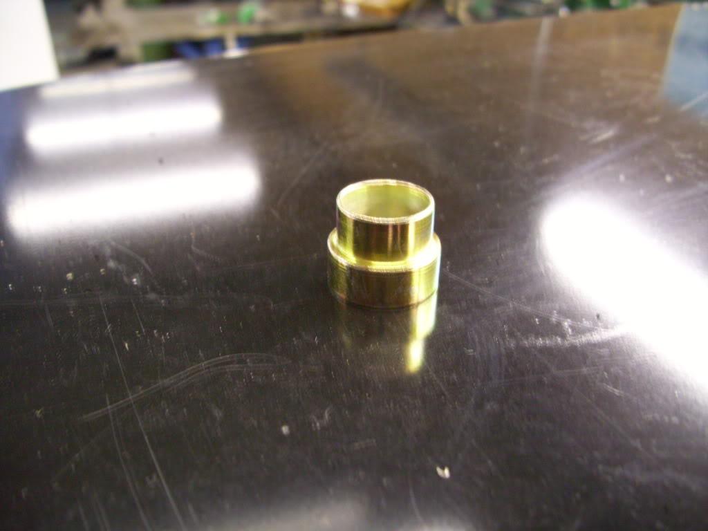
I fabbed up all the strut mounting tabs, the bottom of the strut housings (round discs), the brake line mounting clips, and some mounts for the anti-rotation pins for the hydraulic pistons.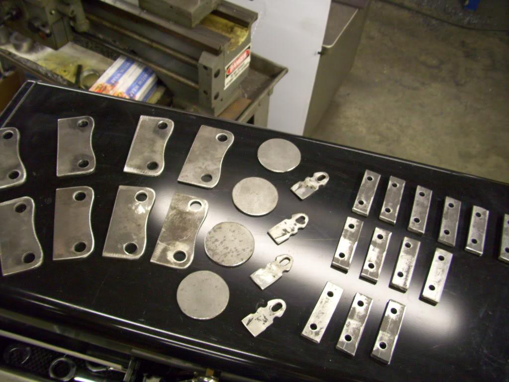
September 3, 2009
I fabbed up all the lower halves of the strut housings, did a bunch of test-fits to make sure everything sat where I wanted, and took measurements for the ride-height limiter spacers. These had to be custom machined and matched to each corner to account for length differences in the strut bodies (from Koni) and the strut housings (I made them).
I made all these strut housing lowers. 4 corners, 1 front spare, 1 rear spare = 6 total.
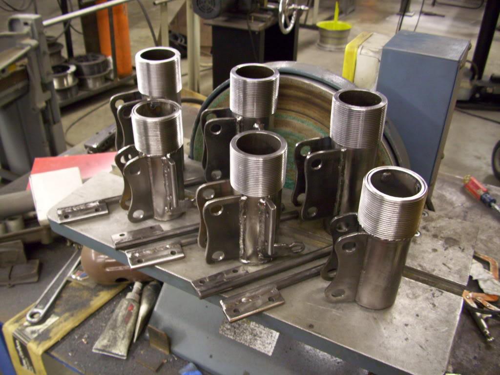
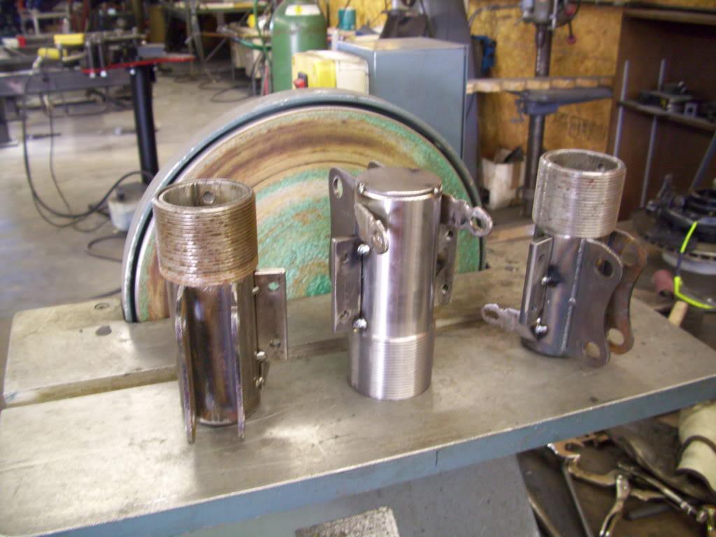
Here's one of the assemblies, before everything got plated.
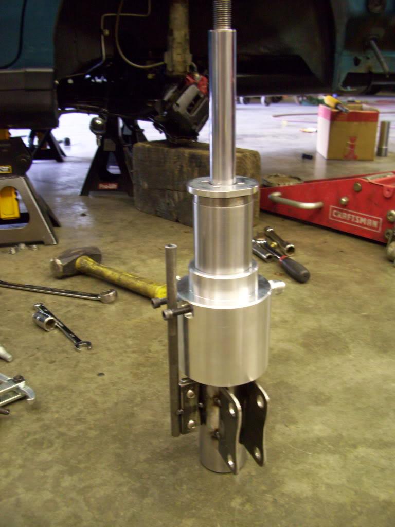
Test fit everything in the car to check for brake line, axle, hydraulic fitting clearance.
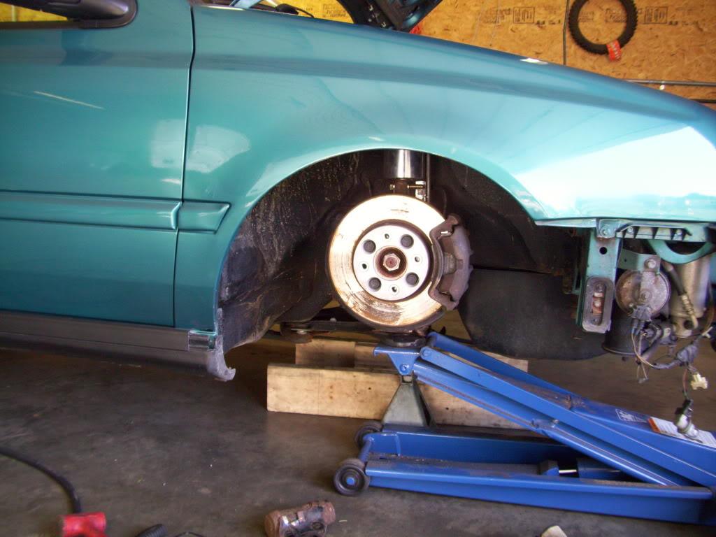
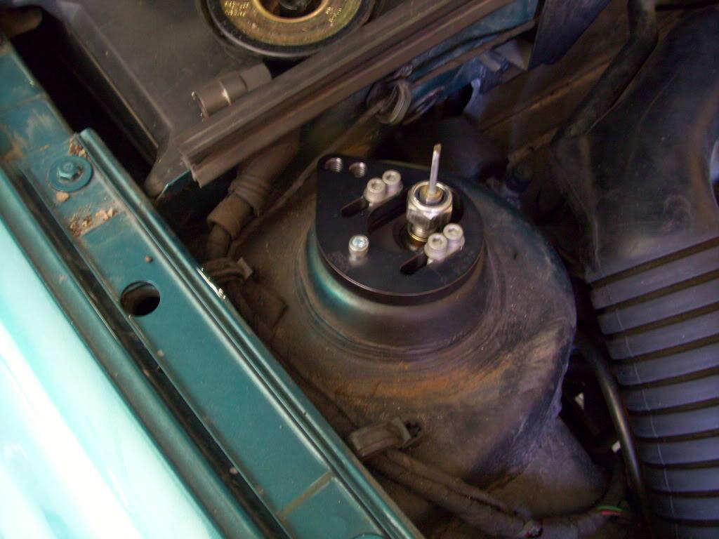
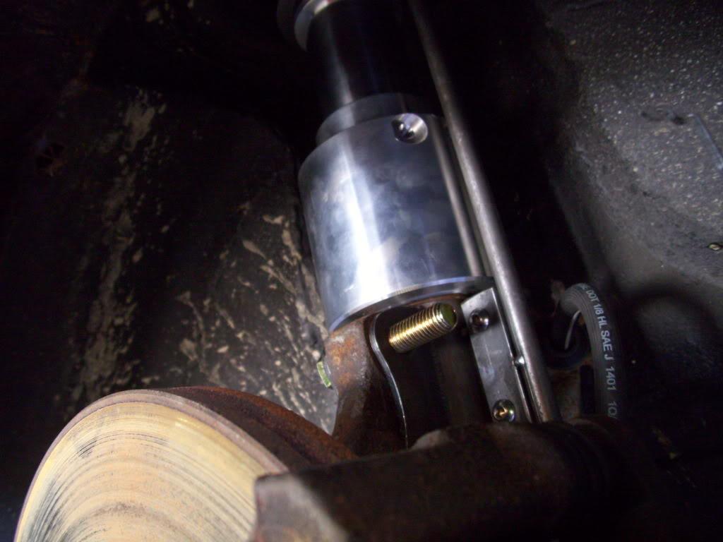
What's up.
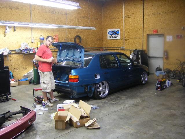
September 6, 2009
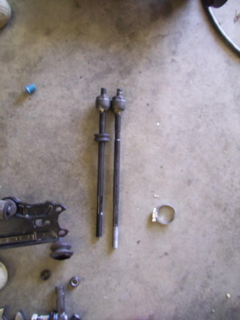
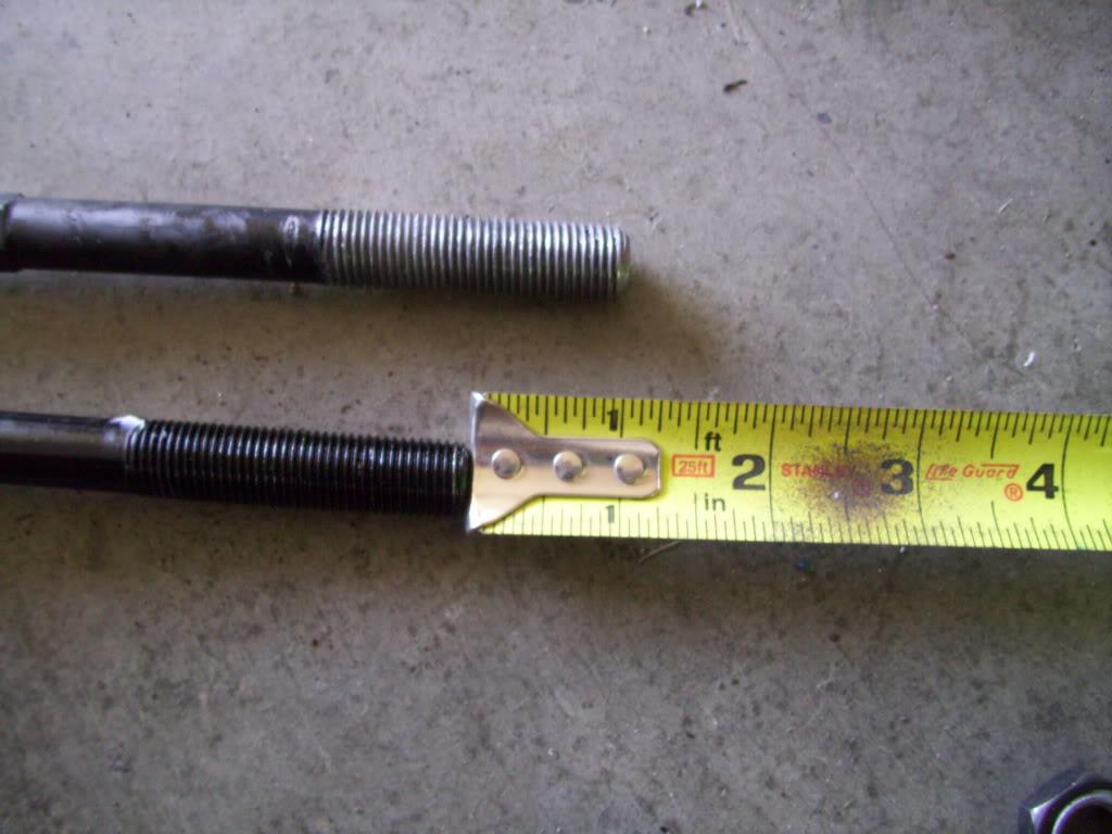
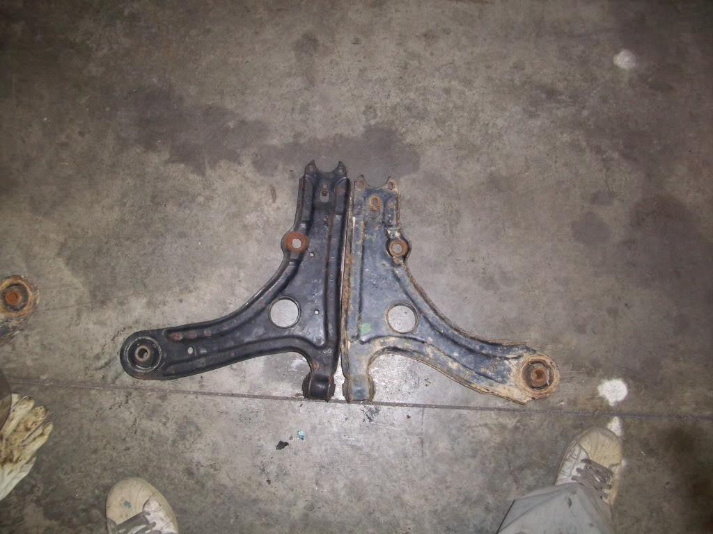
I got some mk2 tie rods because the track was too wide in the rear with the mk3 arms. The mk2 arms are 1" shorter per side, the mk2 tie rods are also 1" shorter per side.
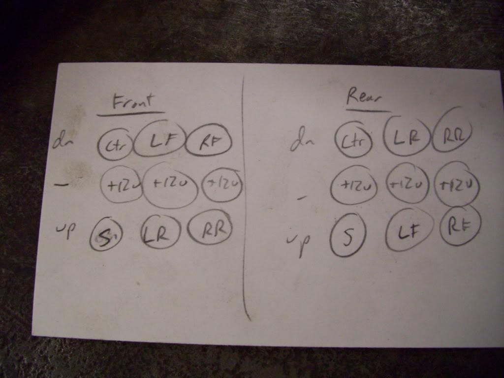
More detailed drawings and schematics. These were made in AutoCAD.

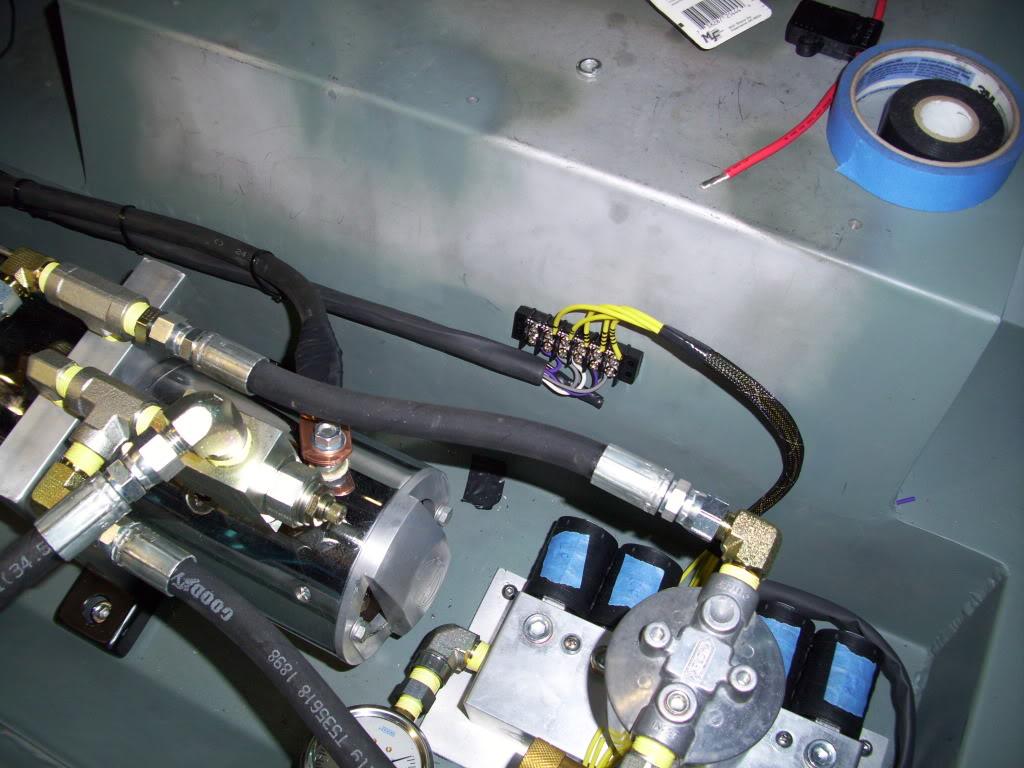
Did some wiring for the switchbox and valves
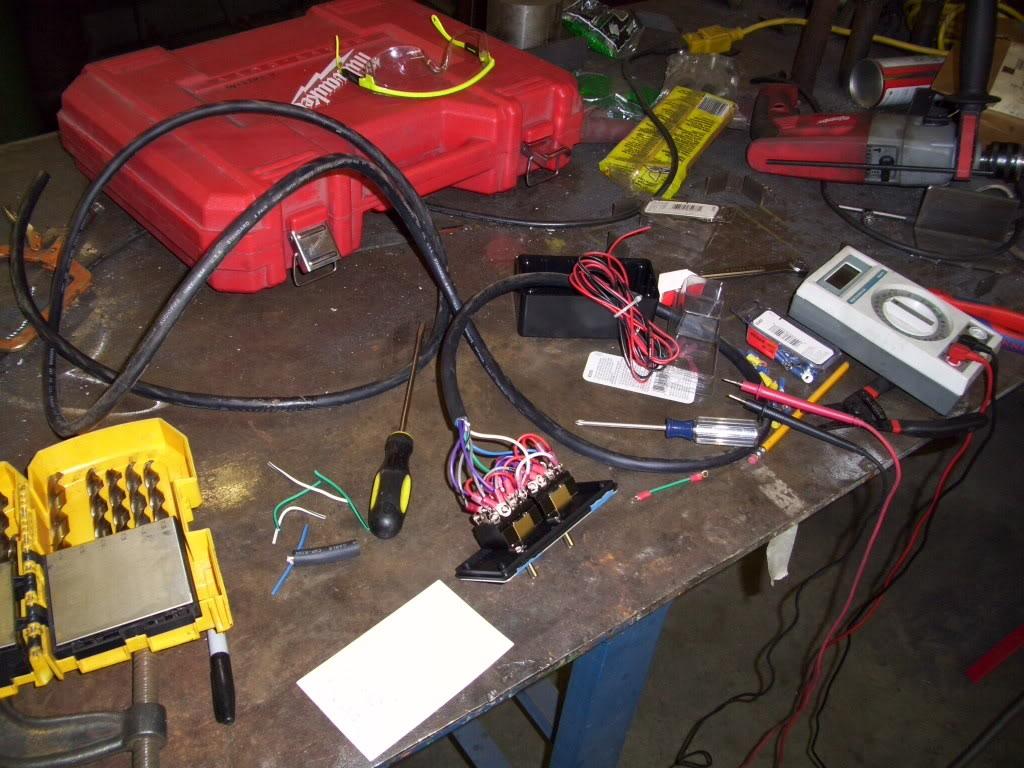
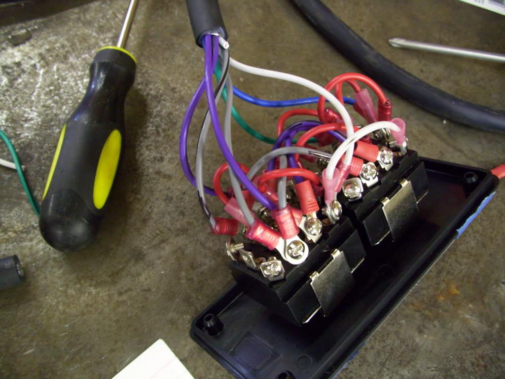
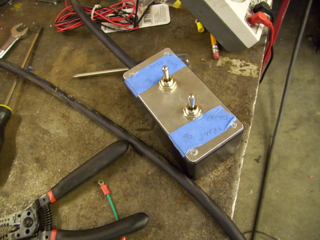
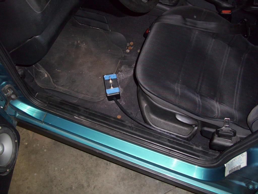
I decided to just leave the switchbox on the end of a cord and hanging on the floor. I want to mount them in the dash, but couldn't decide where to put them. I don't want to cut into my early dash until I'm 100% sure they're staying there, so I left them in the box until I make the final decision.
September 7, 2009
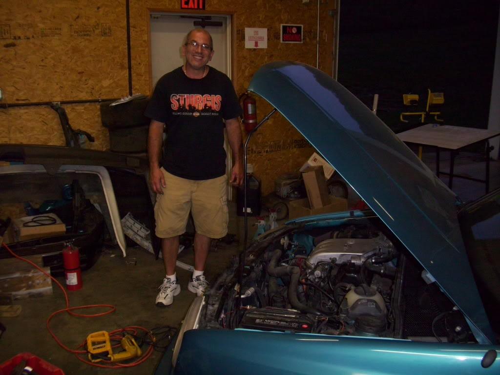
Papa Fazz, wiring professional, comes out to the garage to inspect my work. He approves He has tought me a lot about wiring, he really knows his shiz.
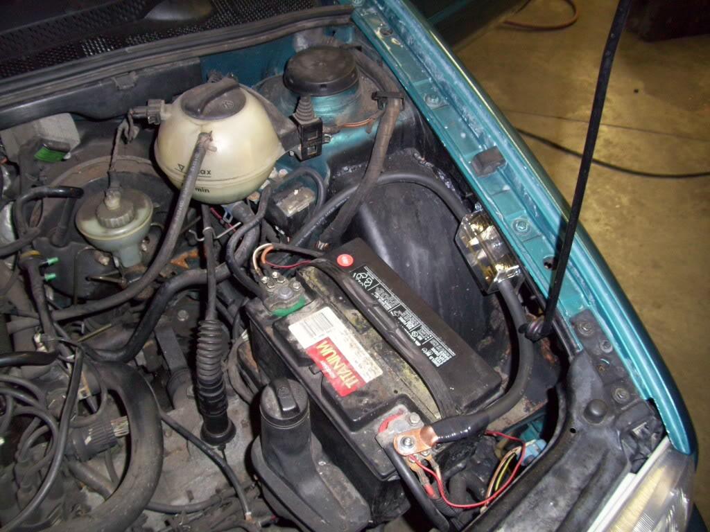
200 Amp fuse for the hydraulic pumps, 2/0 power cable. Yeah.

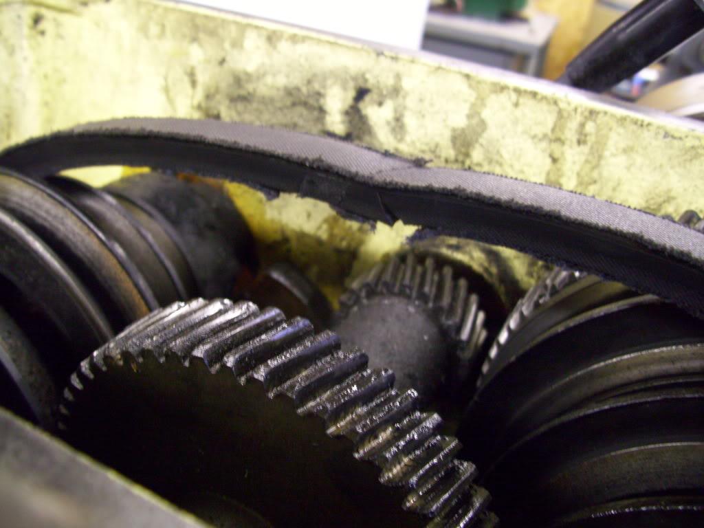
I had 2 more parts to machine, and the drive belt exploded on my lathe. Luckily I was able to use a friend's lathe.
September 8, 2009
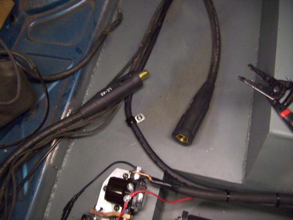
I wired in this quick-disconnect fitting for the power wire in case things go wrong. This is just a welding connector, commonly available.
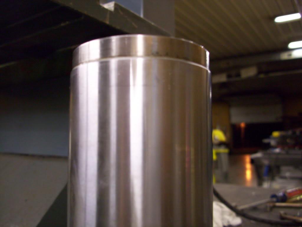
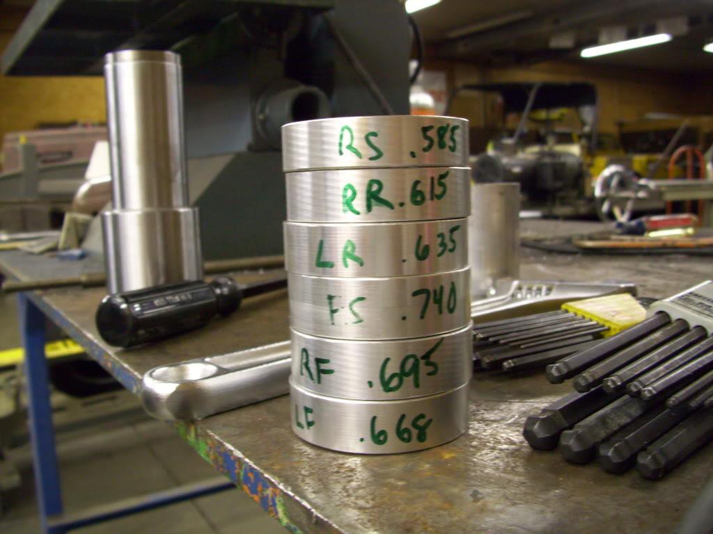
I machined these travel limiters for the suspension. These go on top of the strut housings which limit me to exactly 2.1" of strut stroke per corner. I intentionally made this a separate piece so I could make them different to accomodate for length differences in the housings, which weren't super precise.
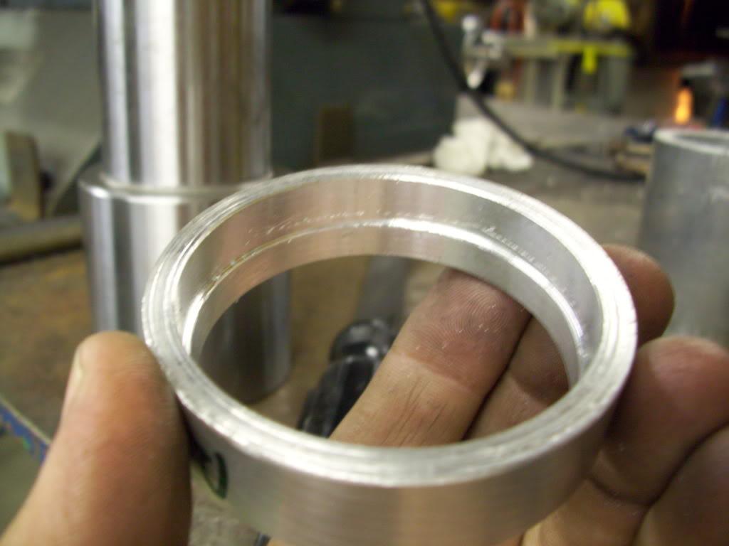
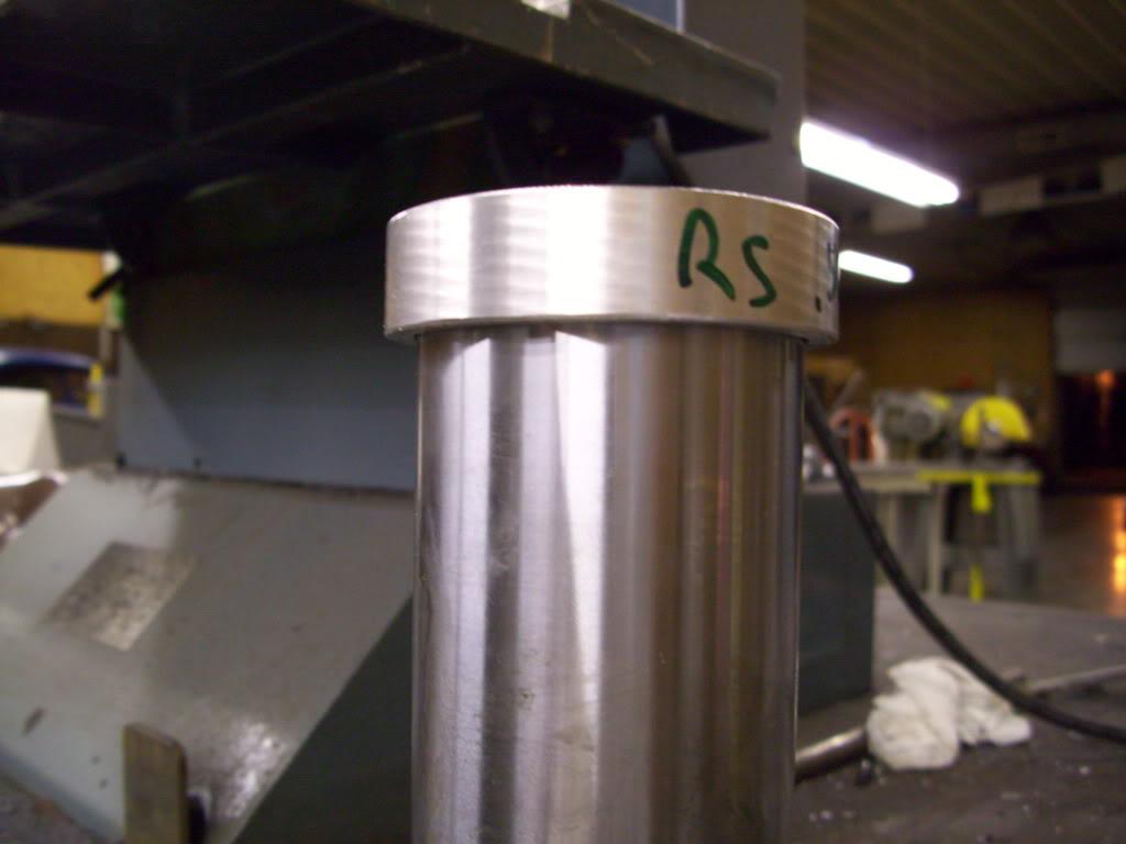
Each one was marked for which corner it went into.
September 09, 2009
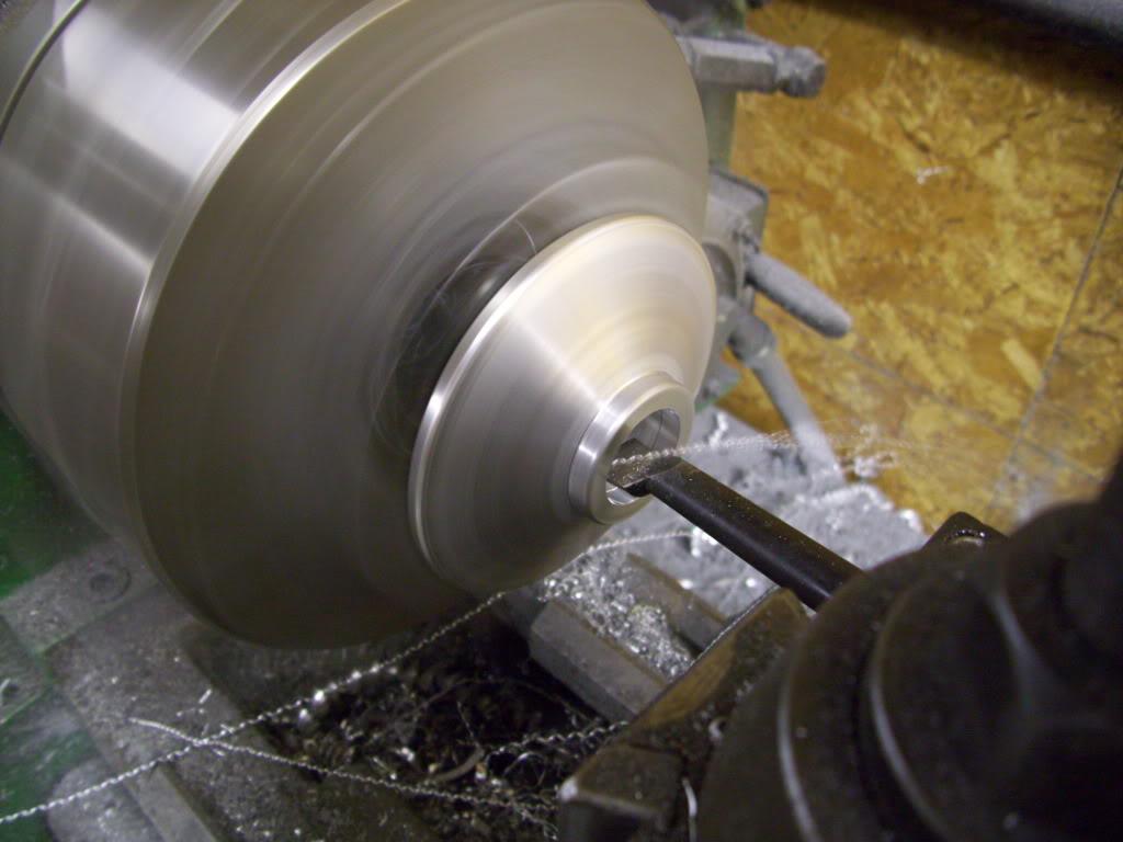
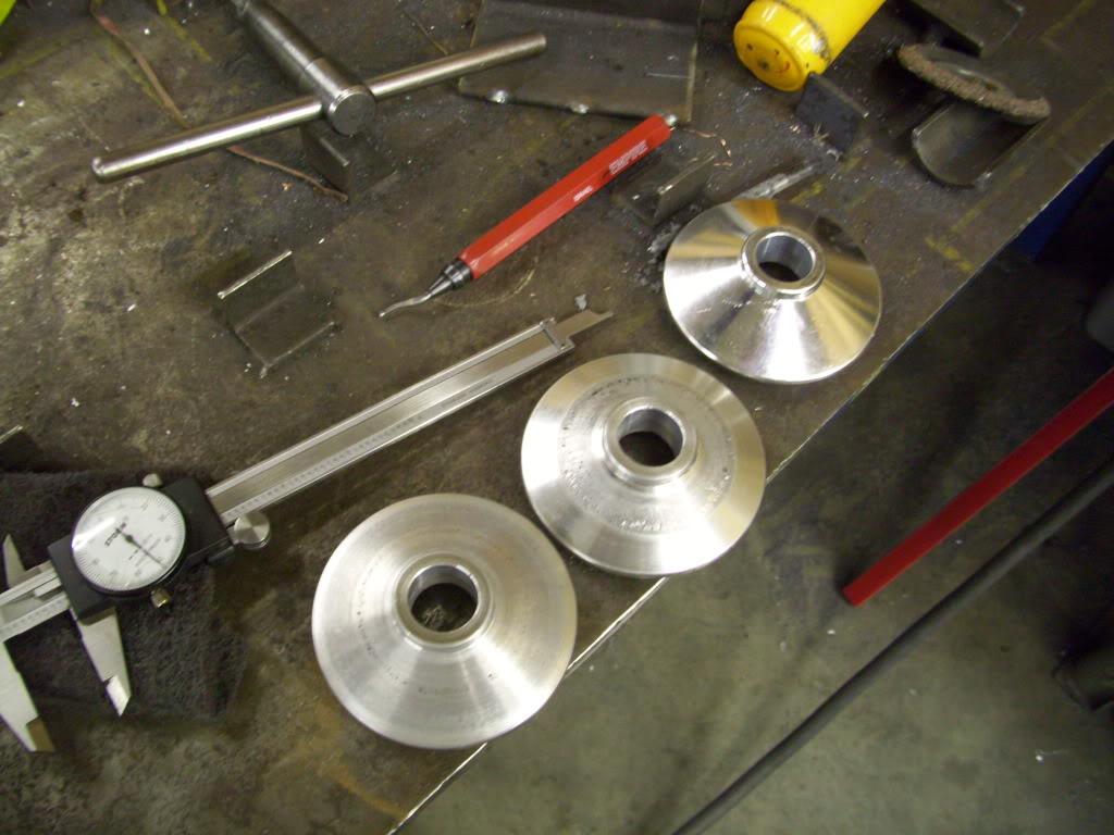
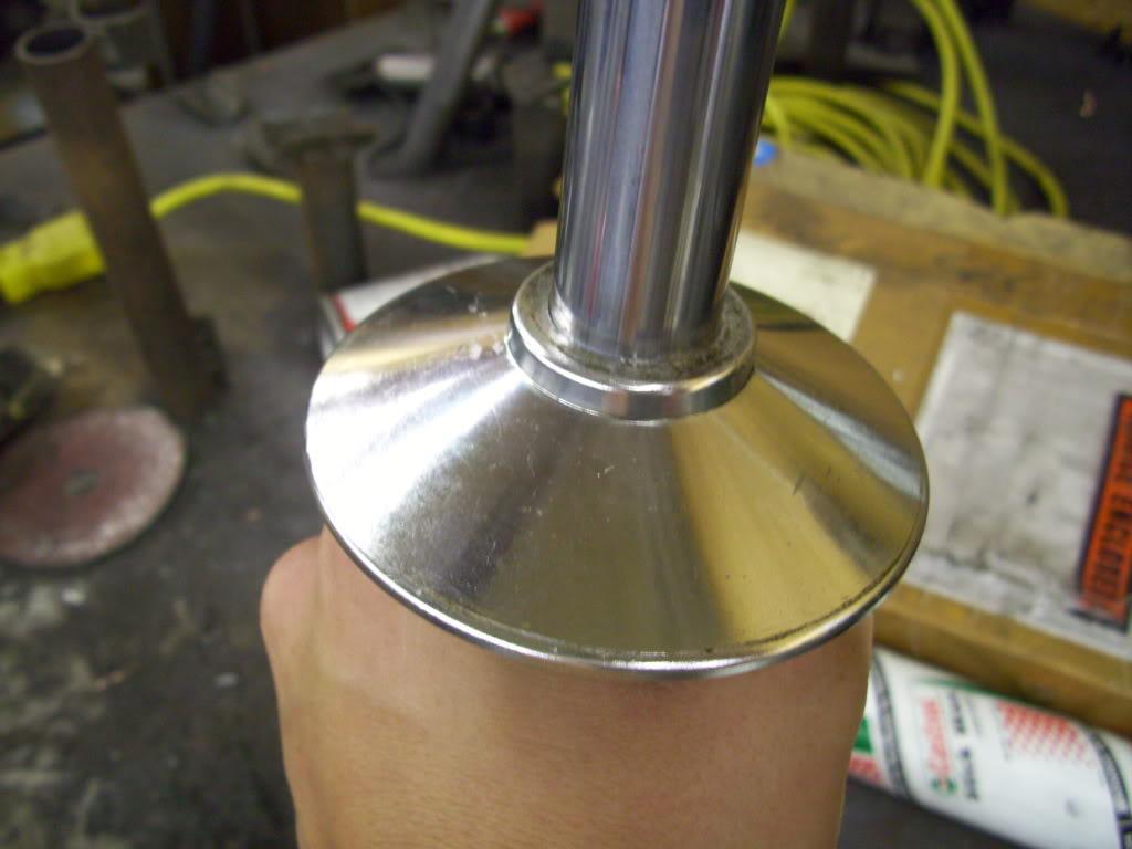
I had to bore out the upper springs seats I found from the ebay coilover kit to fit over the Koni strut shafts.
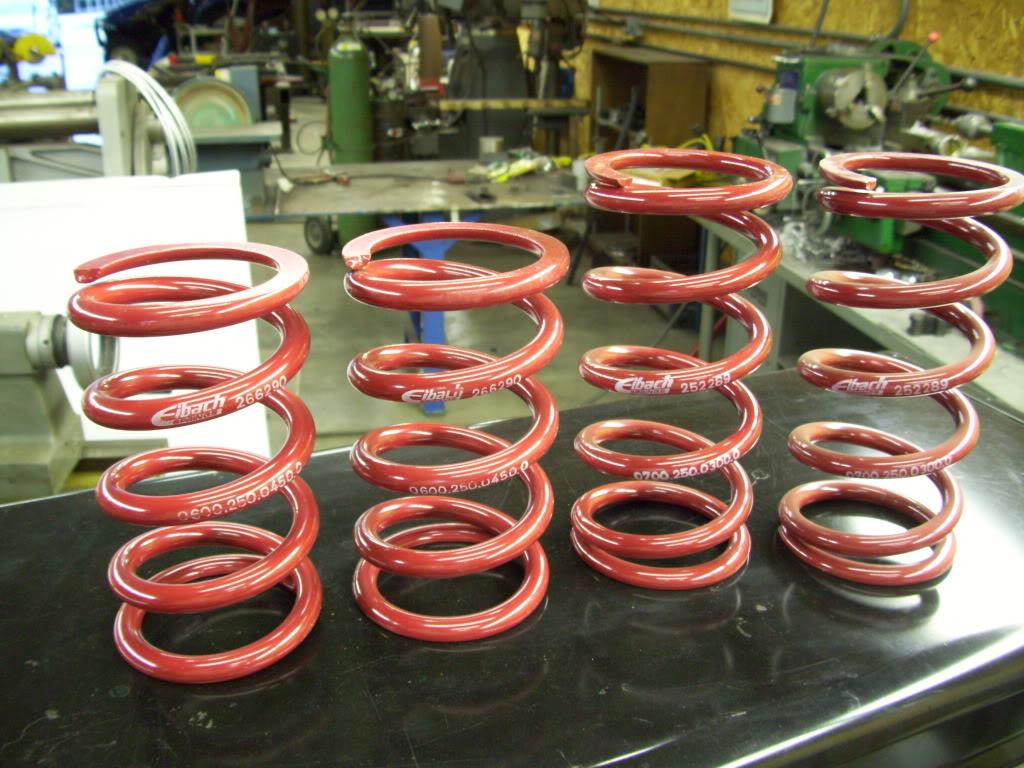
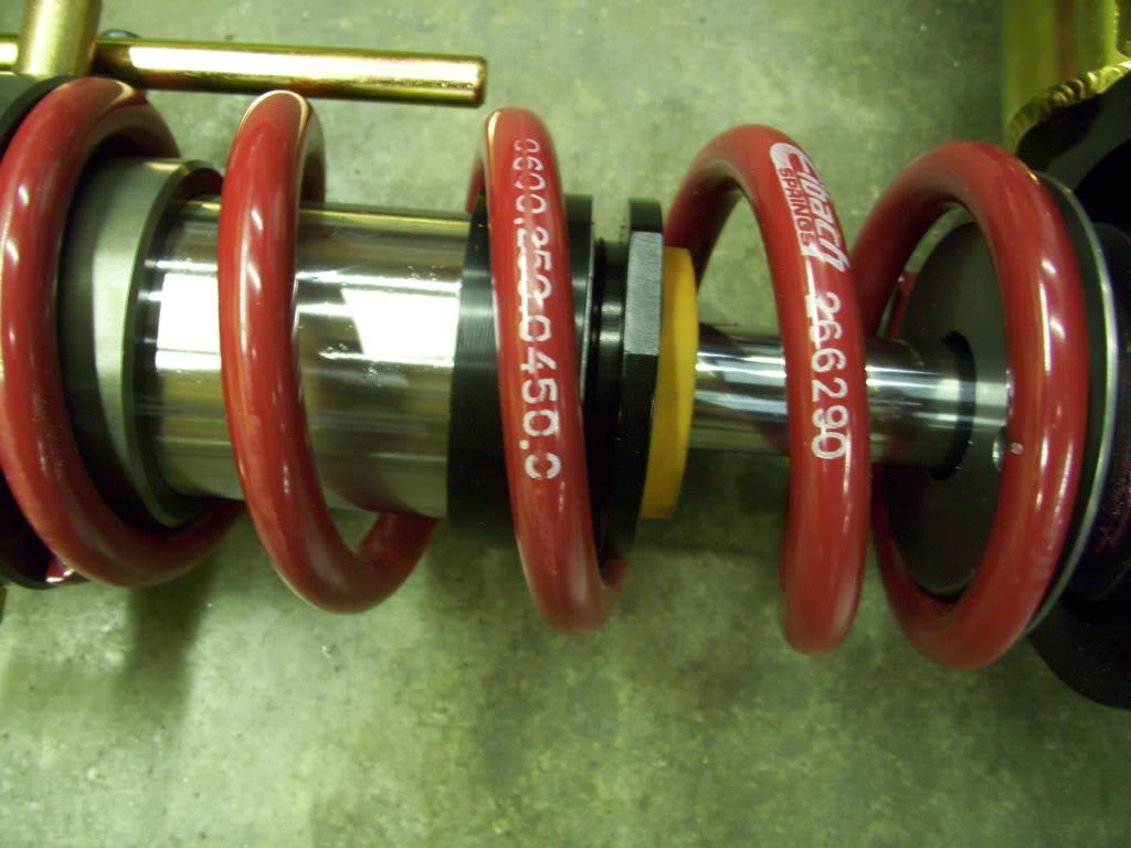
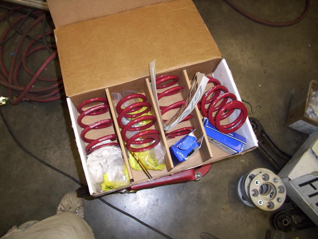
I got two sets of Eibach springs. 6" long 450lb/in for the front; 7" long 300lb/in for the rear. These are only 12% stiffer than the springs in my H&R coilovers, so the ride quality should be pretty good. I did some calculations based on the corner measurements I took a few weeks prior, and the numbers looked good.
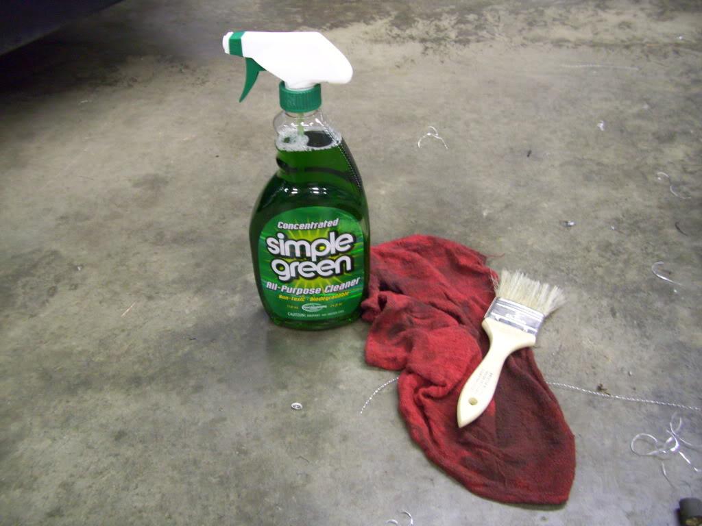
I also started cleaning the 8+ months of garage dust out of the rear trunk, since most of the hardcore fab work was done.
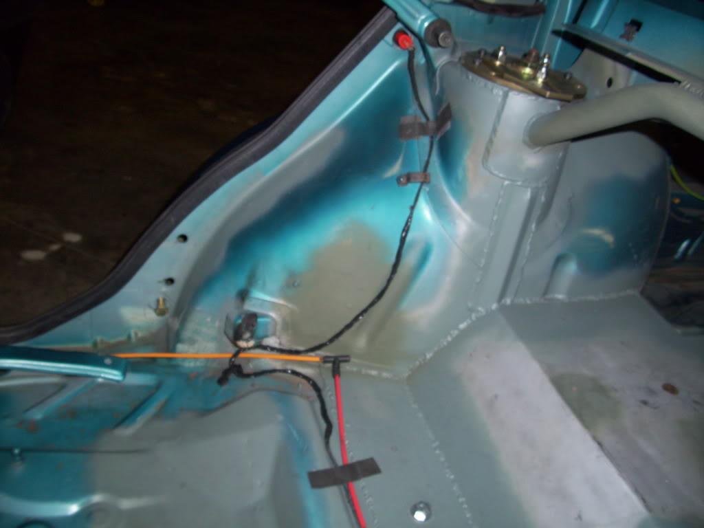
I also started cleaning up some of the wiring I had been moving around during welding. I even replaced a section I caught on fire
I melted one of the vacuum lines that goes to the rear trunk lock, so I took some measurements to order some new line.
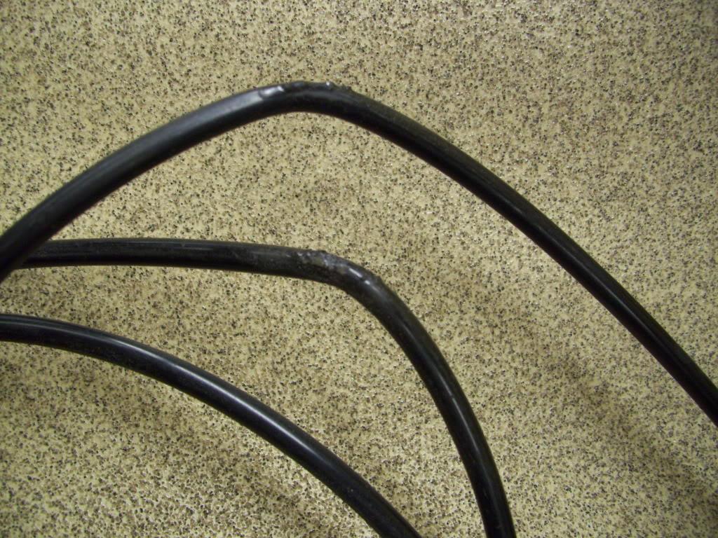
Oops!
To be continued...
September 10, 2009
I got everything back from plating!!!
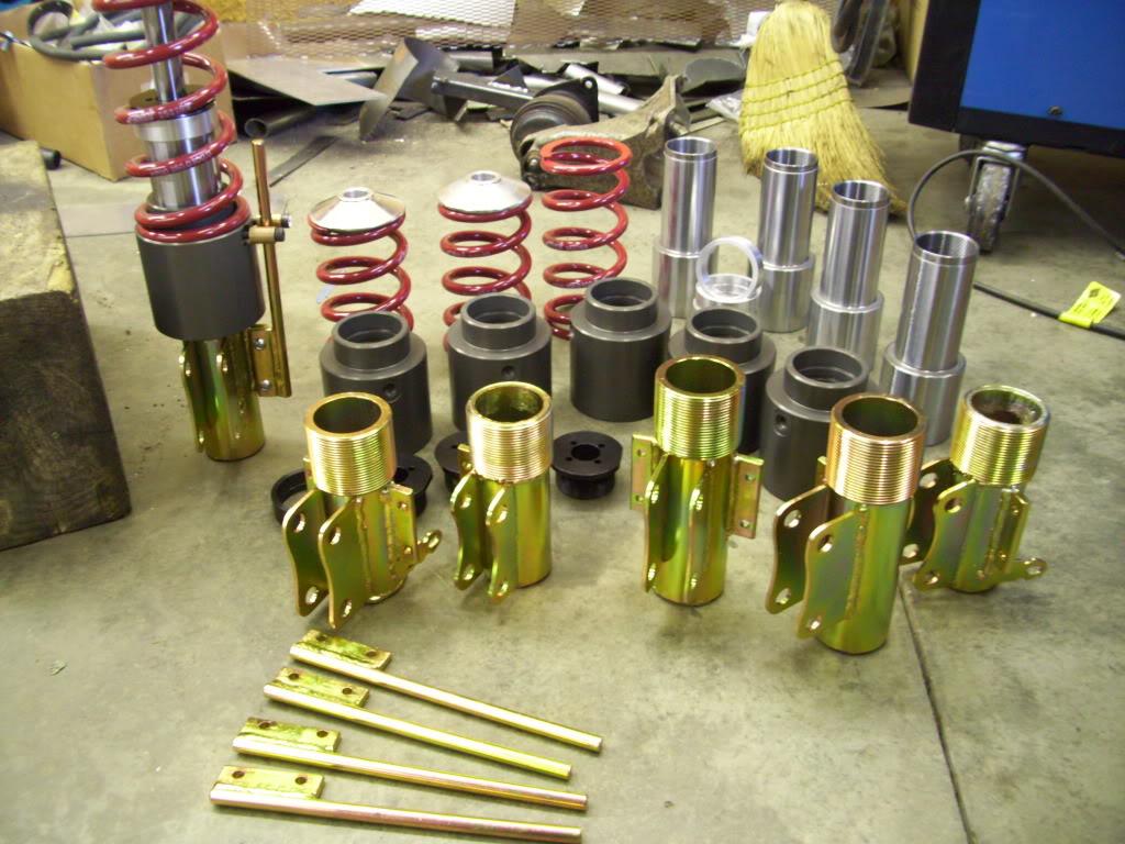
Strut lowers and anti-rotation pins are Zinc plated with yellow chromate. This is very common on everything from Grade 8 bolts to coilovers.
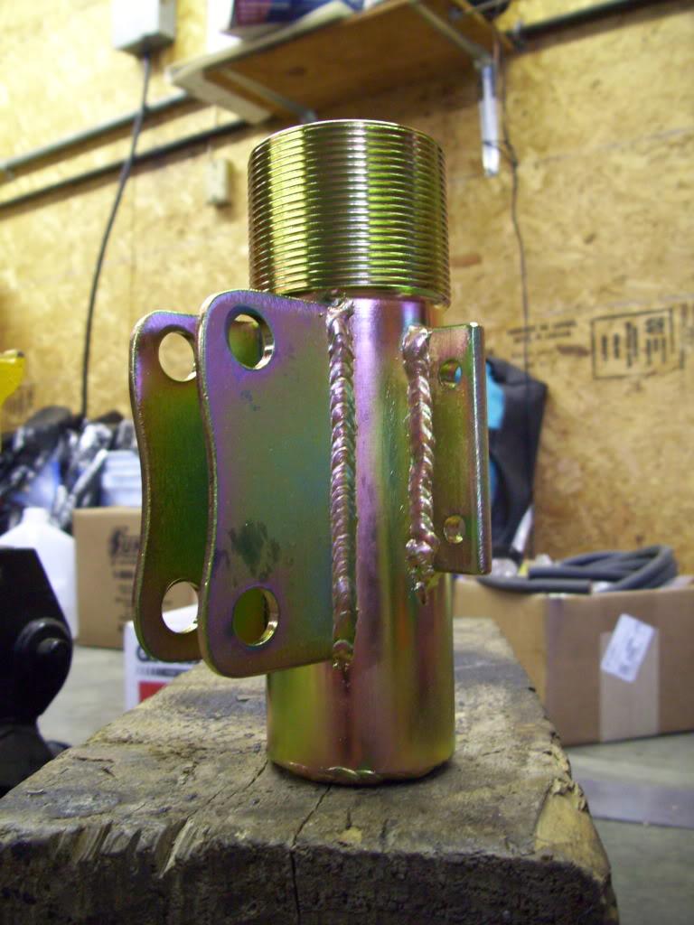
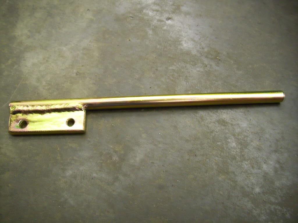
Strut caps are black anodized.
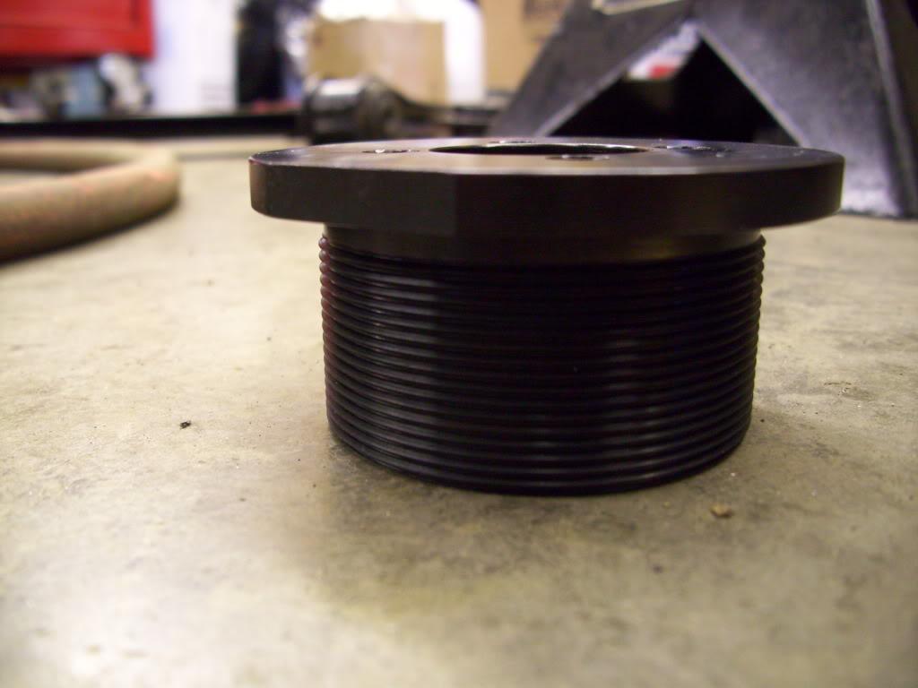
Here are the housings, these have been done for months and now I finally get to assemble everything!
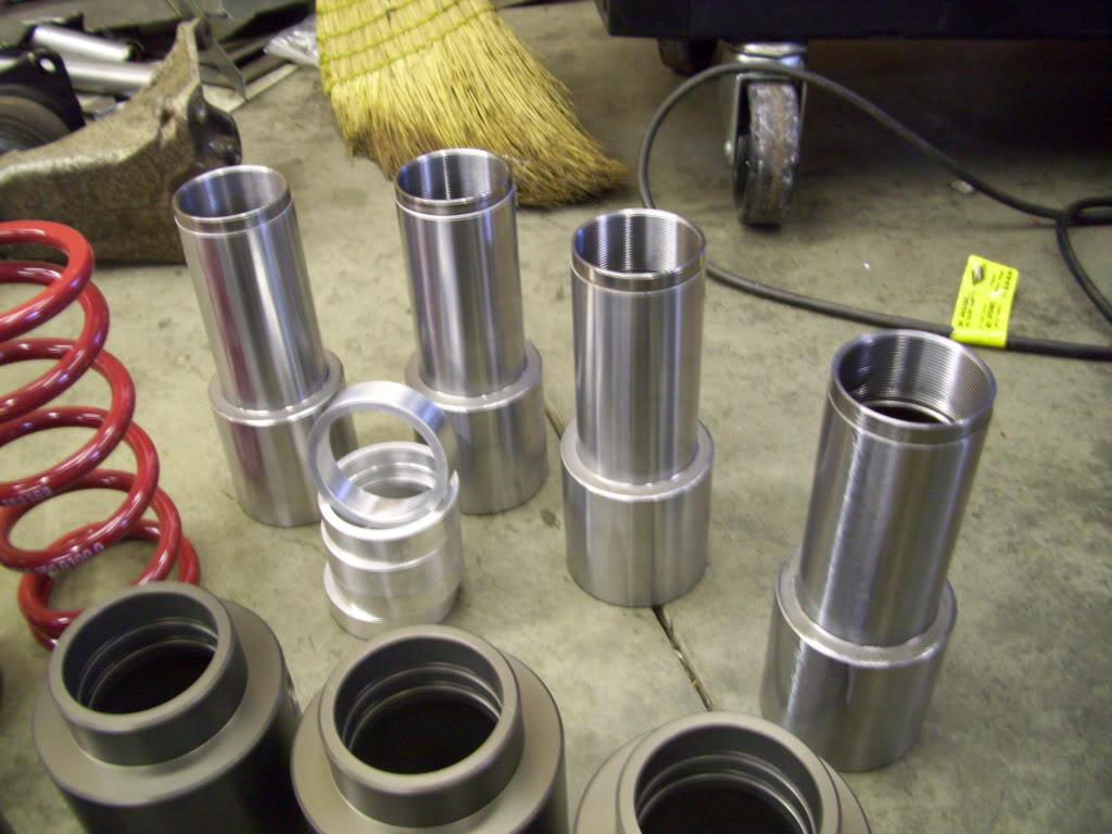
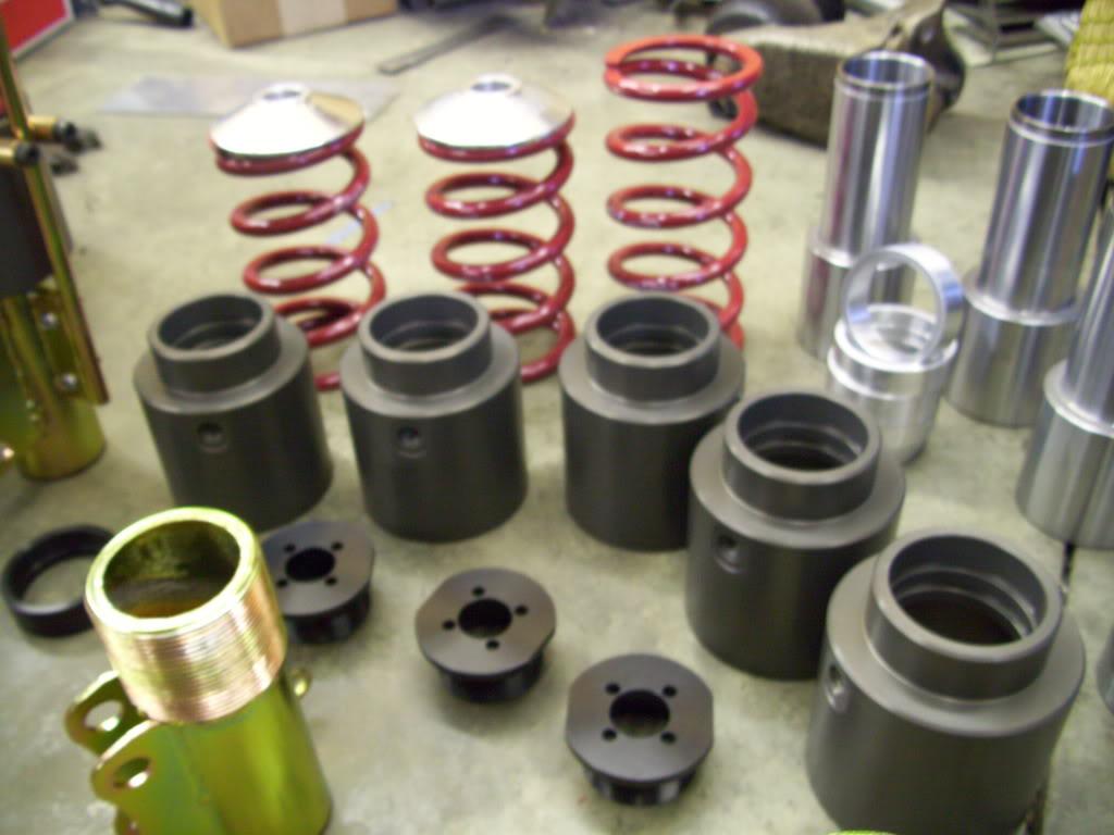
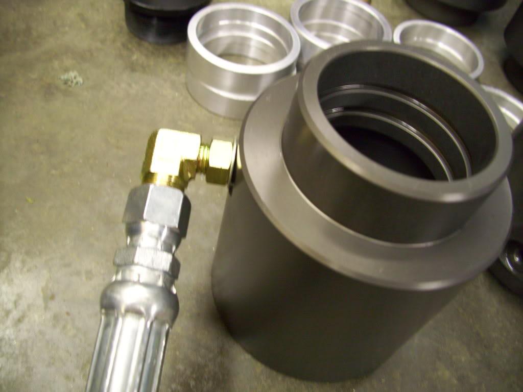
Here's where the hydraulic fitting will let fluid into the pistons
Here is one of the struts, all assembled. In this pic, it's all the way down:
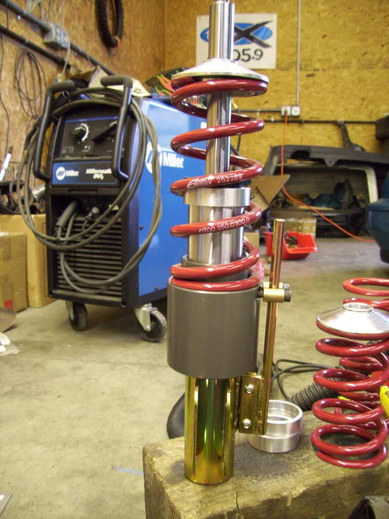
In this pic, it's all the way up.
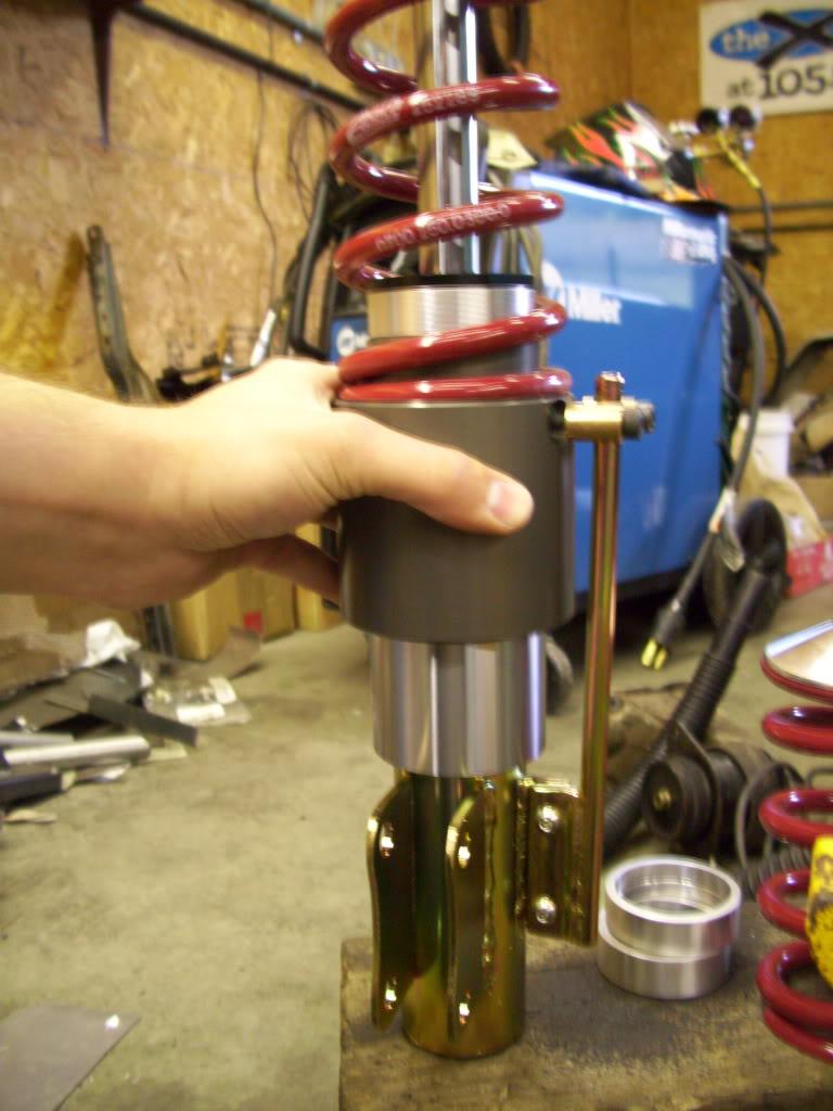
The hydraulic fluid enters the fitting and because of the stepped bore and stepped housing, what you end up with is a hollow cylinder around the outside of the strut. I've got 2.10" of stroke in each corner.
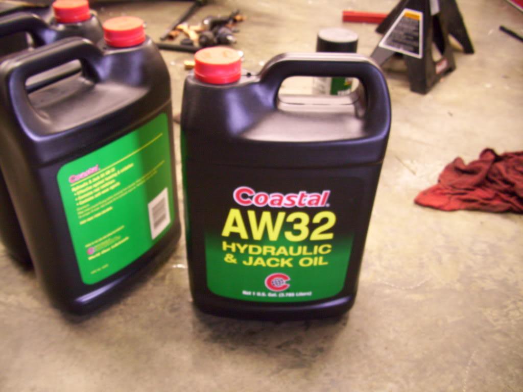
I also made the decision on which hydraulic fluid I wanted to run. This stuff has the right viscosity, price, and availability. I didn't want to run anything crazy just in case I need to get more, and this stuff is available from any auto parts store. Lots of lowrider guys run ND-30 also, but I chose AW-32 because it's real hydraulic fluid.
September 11, 2009
Got the struts assembled and installed into the car.
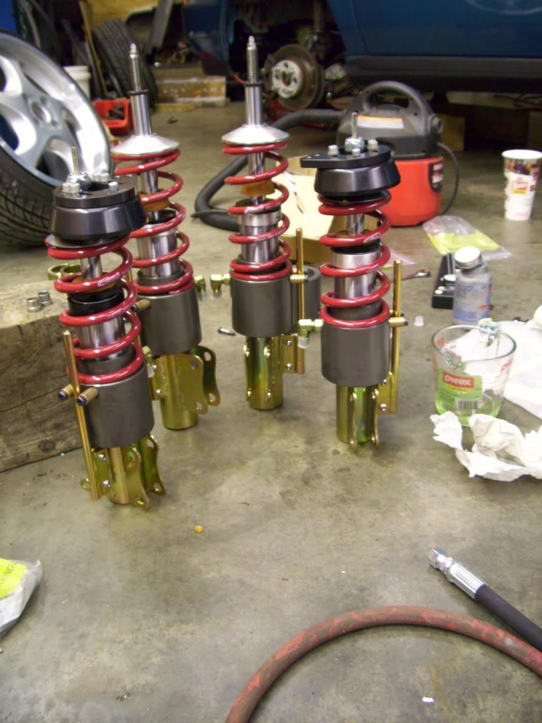
These pins are just to prevent the piston from rotating on the housing so the fitting doesn't hit the tire. Not the most elegant solution, but it was the best I could come up with at the price I wanted.
Ground control uppers all mounted up.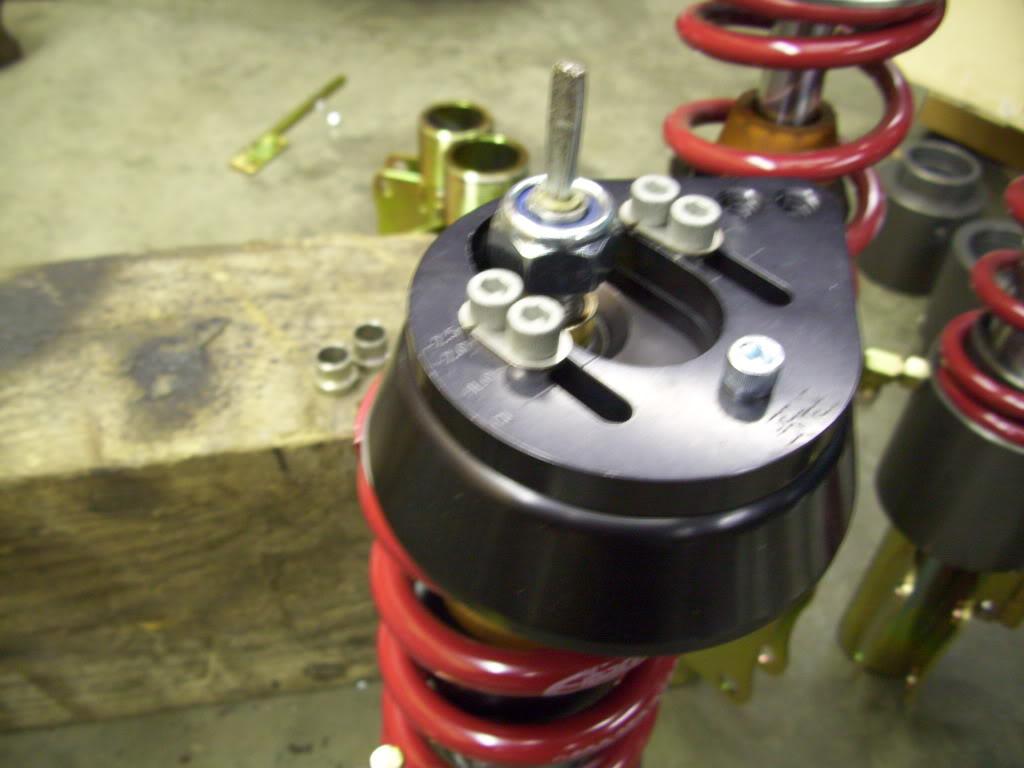
Rear bumpstops.
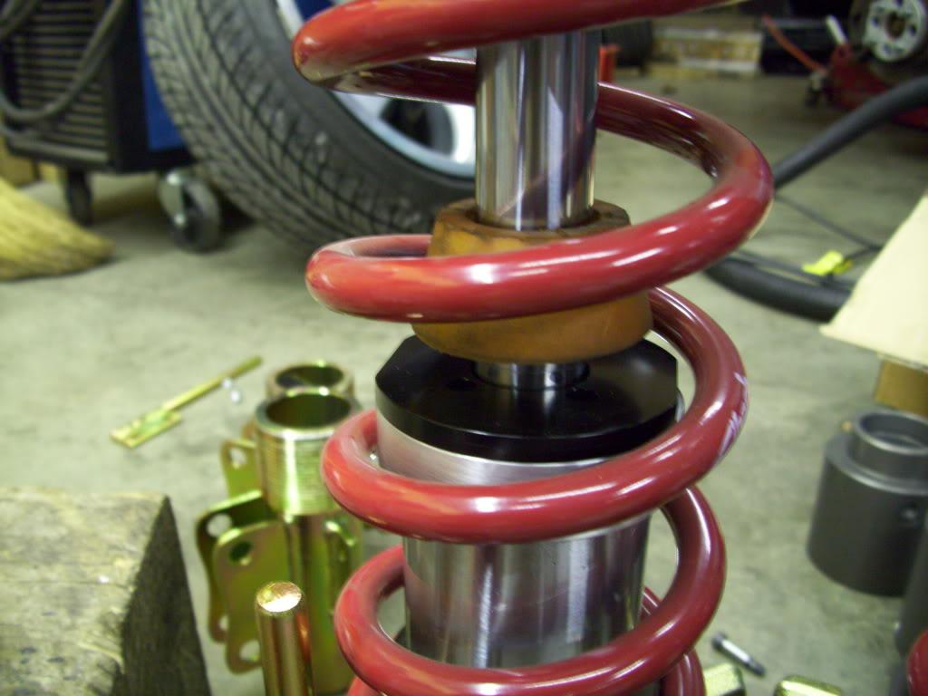
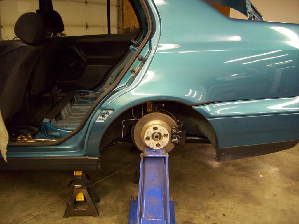

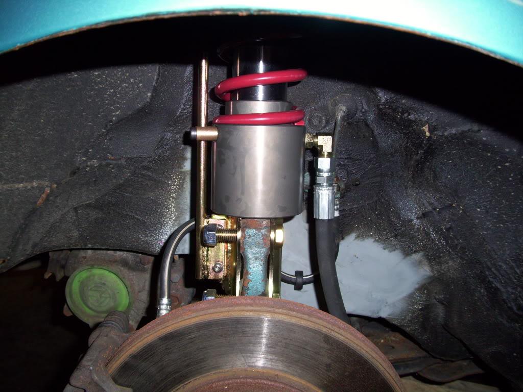
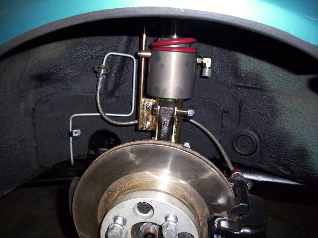
I had a wee little bumpstop in the fronts, which I ended up cutting out later, but might reinstall at some point.
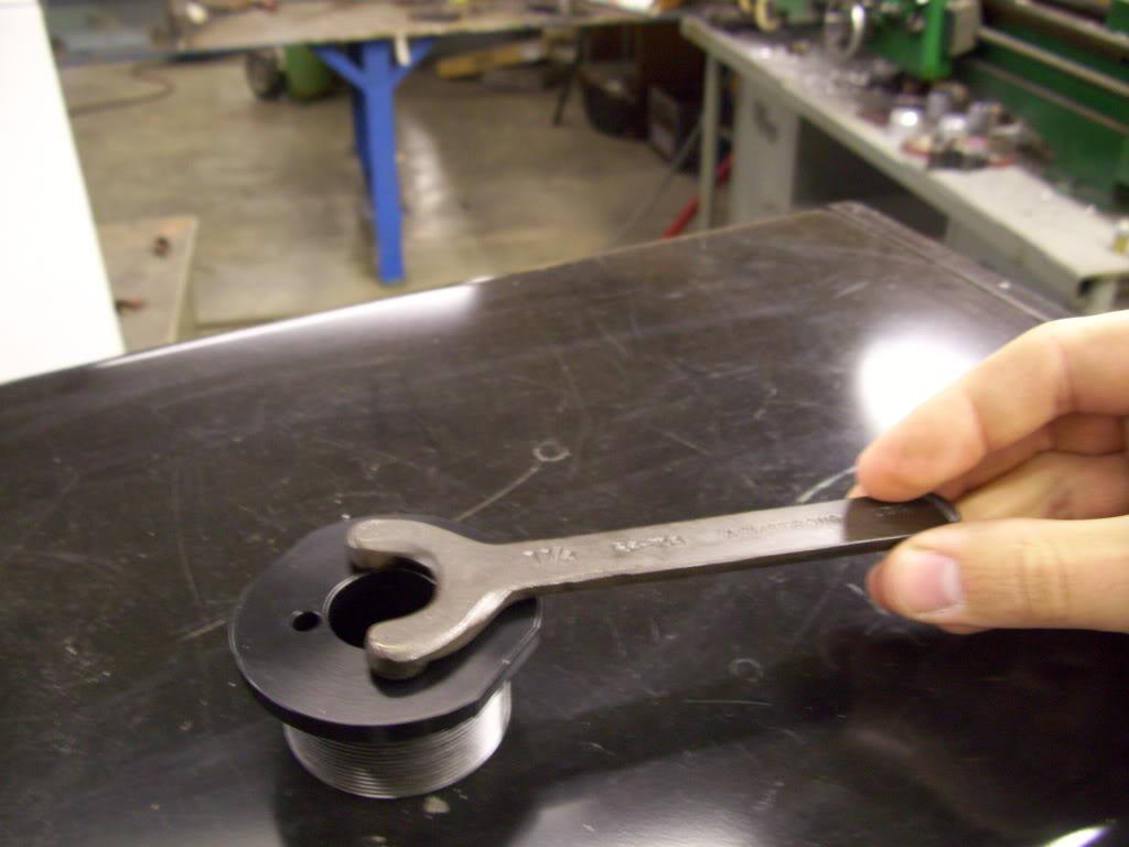
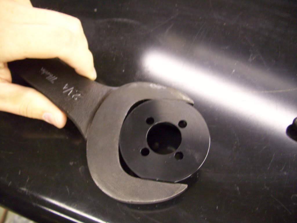
Remember all that machining I did on the strut caps? That was for these two wrenches. I use the wrench flats mostly, then the spanner holes are just in case it seizes up so I can still disassemble everything in the future.
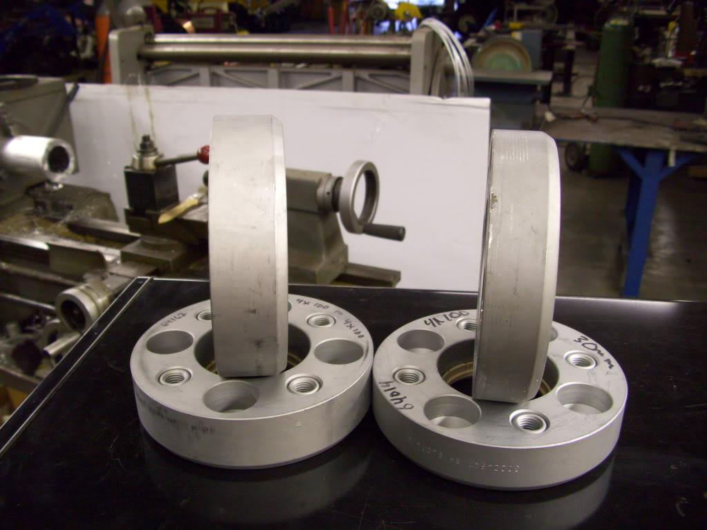
I also got the new adapters from GMP Performance. The Artecs use the RH adapter system wheel mounting. The wheel itself is ET60, they came with 25mm adapters to make them ET35. I ordered a pair of 30mm adapters and a pair of 35mm adapters. These are the ones that ended up in the car, for final offset of ET30 and ET25 front/rear. That doesn't mean a whole lot since the whole rear setup is completely new!
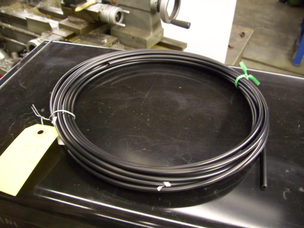
I also got some new 5mm vacuum hose from Mcmaster for the rear vacuum hose that I melted.
September 12, 2009
Juiced.
Youtube video of hitting switches for the first time!
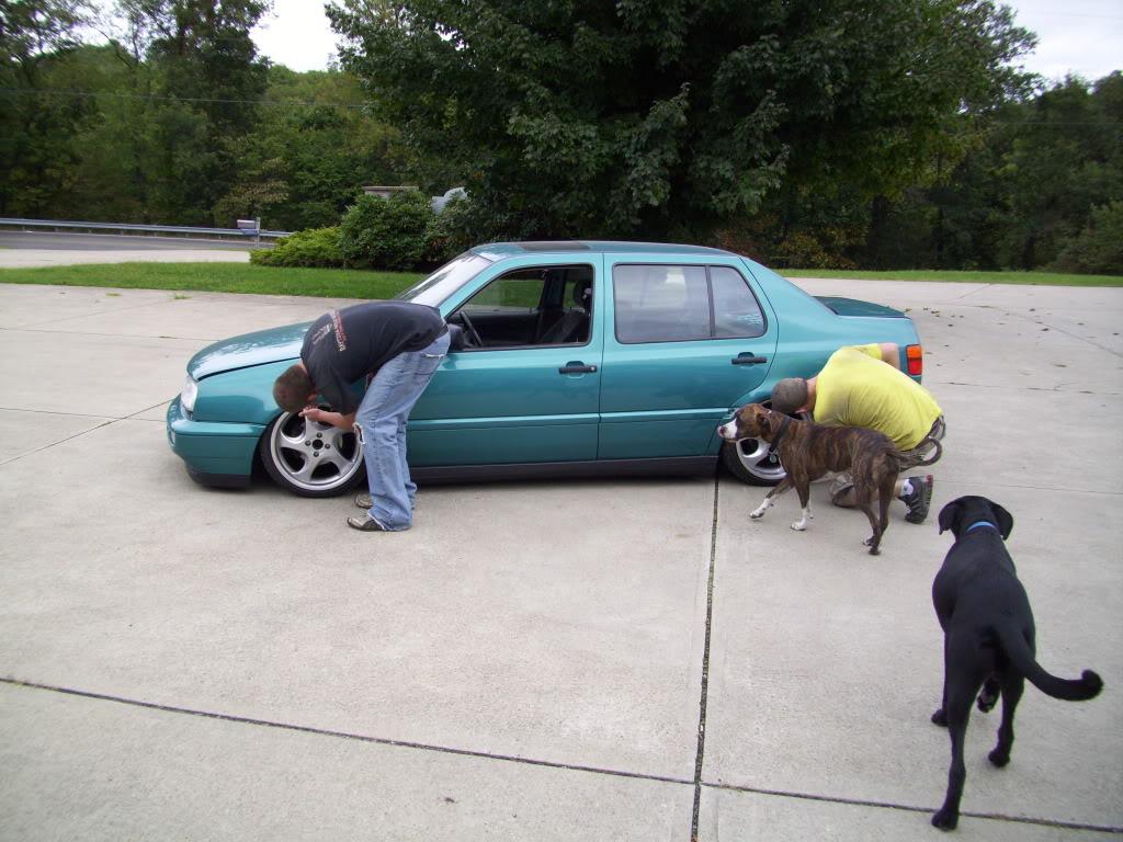
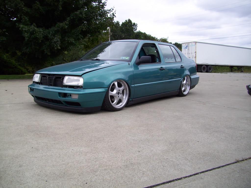

I drove it a few miles down the road to the gas station; it felt so great to get it back on the road!!!

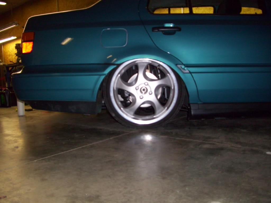
So after all was worked out, the car was still 1/2" too high. The springs I ordered were too long, the frame was not on the ground. Failure. After a lot of testing, I figured it was just the springs, which was a huge relief. It sucks I have to buy more springs, but I really can't complain because I can have the car on the ground with a phone call and a credit card number. New springs on order from Ground Control, 2nd day air shipping!
September 16, 2009
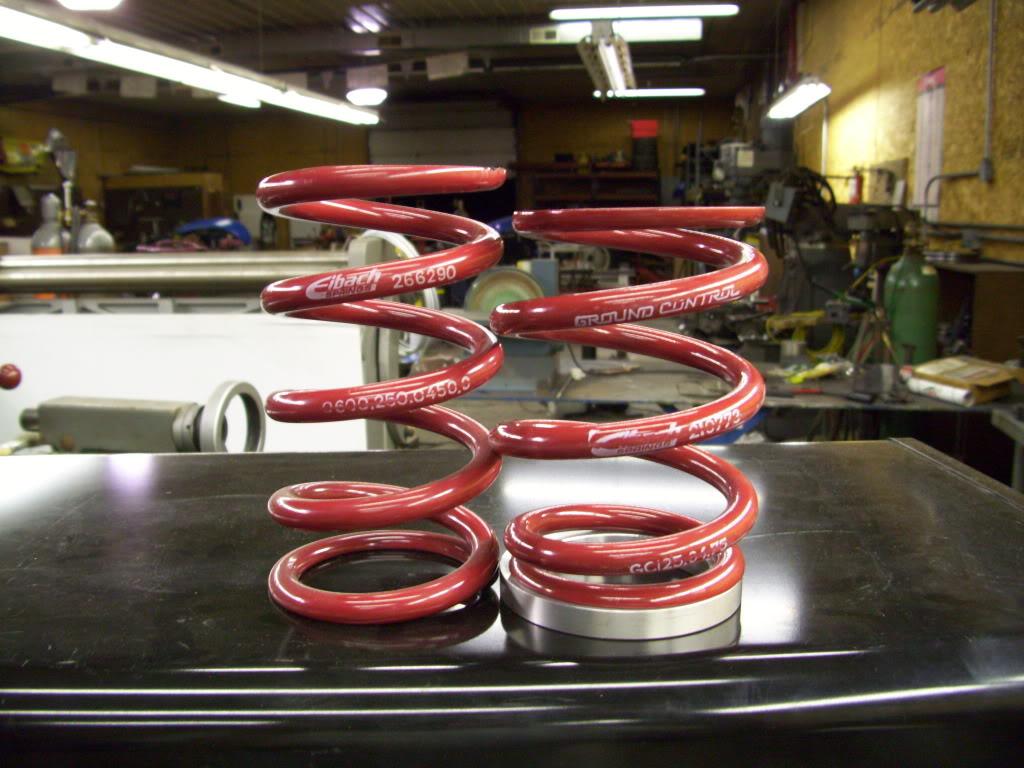
New springs arrive. 5" 425lb/in fronts, 6" 300lb/in rears. The rates are a little different than what I chose originally, but these are the shortest springs you can buy from ground Control.
I machined spacers to go under the springs, I didn't need it a full 1" lower, I only needed 1/2" lower. Since the springs were 1" shorter, I machined a 1/2" spacer.
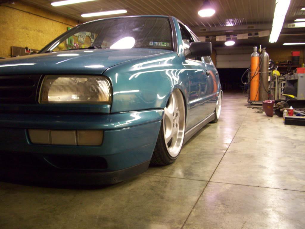
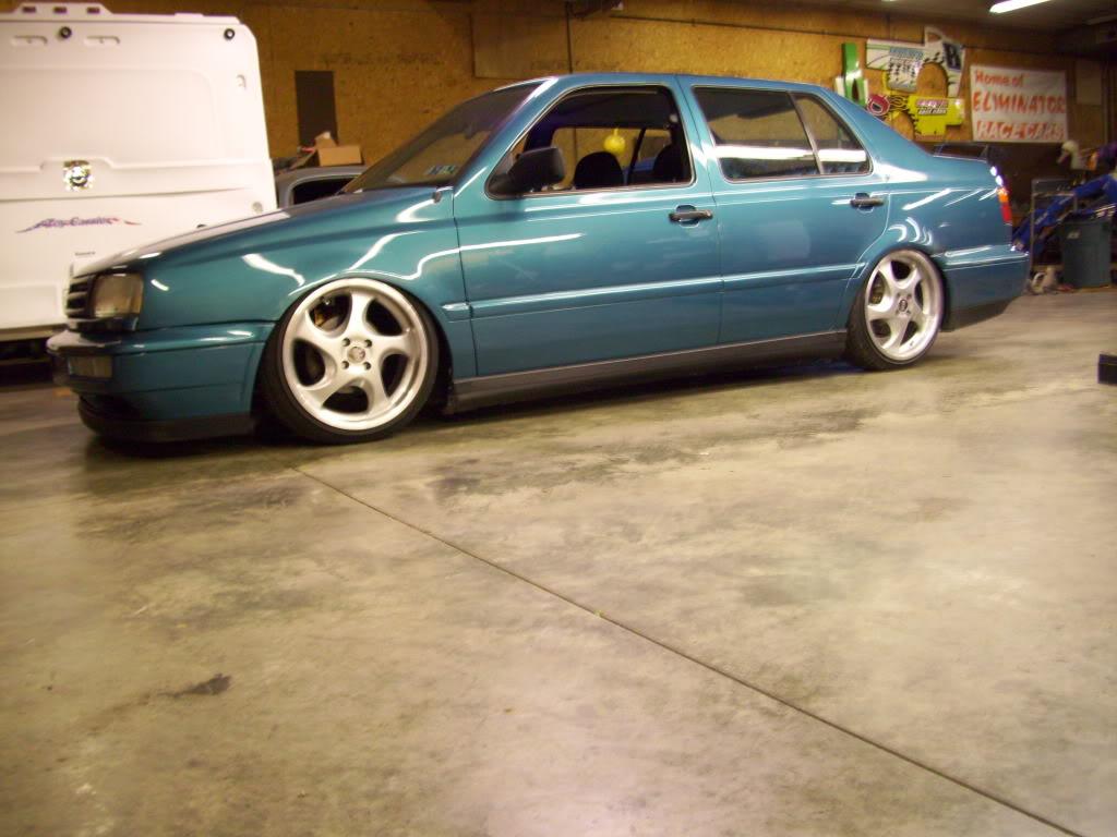
That got the car sooooooo close to laying frame. It was honestly about .030' away from laying frame... I couldn't slip a piece of paper under but it didn't scrape on the super-flat concrete floors!
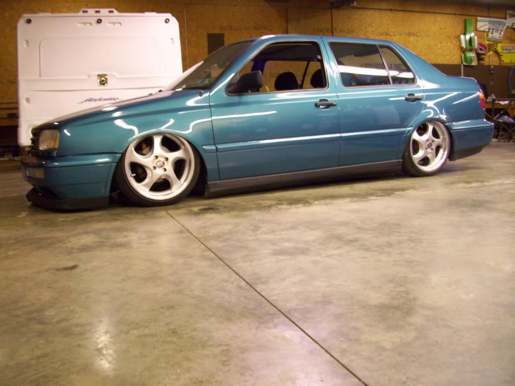

This is about as close as you can get without laying!!!
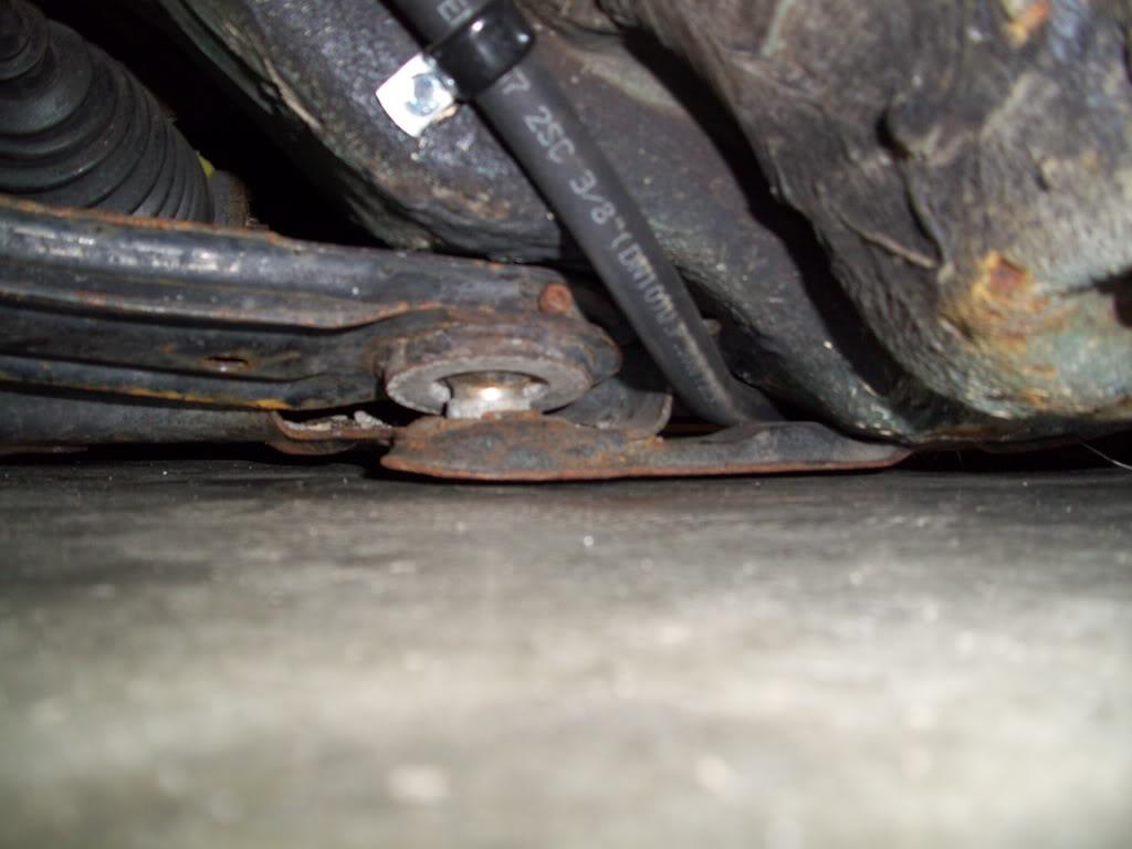
This is all the way up; 1-1/2" above ground lol!
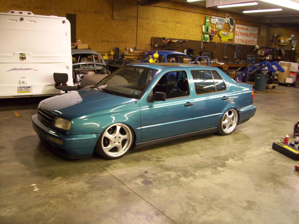
I'm going to bed, I will try to finish it up tomorrow or Tuesday night, I still need to make some updates to the 3D CAD model of the suspension so I can post those pics.
September 20, 2009
I think I got lazy with the dates toward the end... Anything from here forward took place between September 16th and September 24th 2009. The whole last two weeks was a blur, I honestly have better memory of the April/May stuff than last week
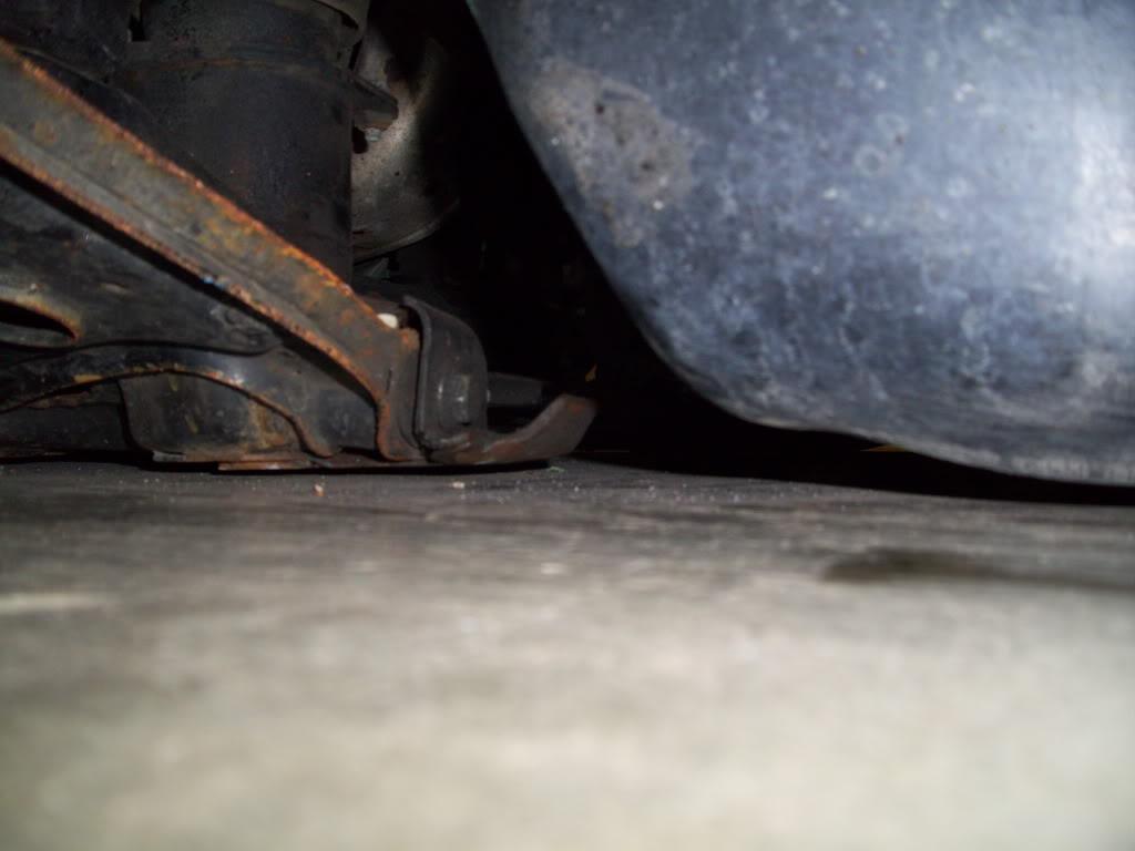
I forgot to take pics (was in a hurry) but I cut two very small notches for the front tie rods and the car laid on the ground. That's all it took to get that last little wee bit.
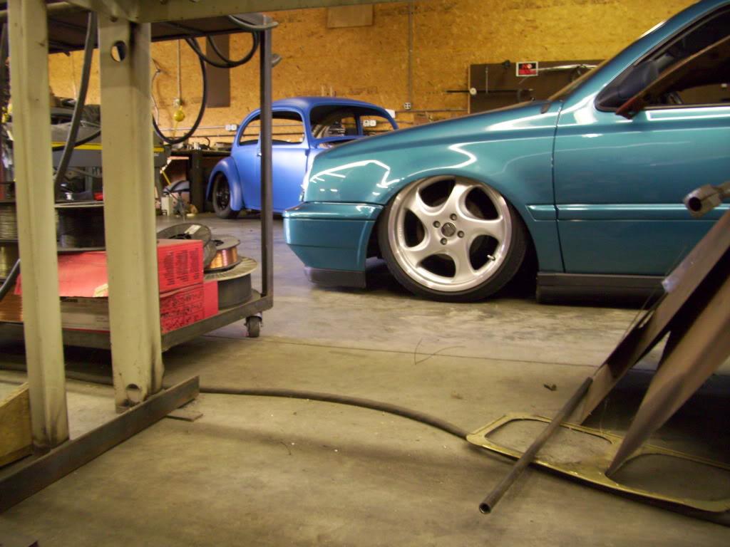
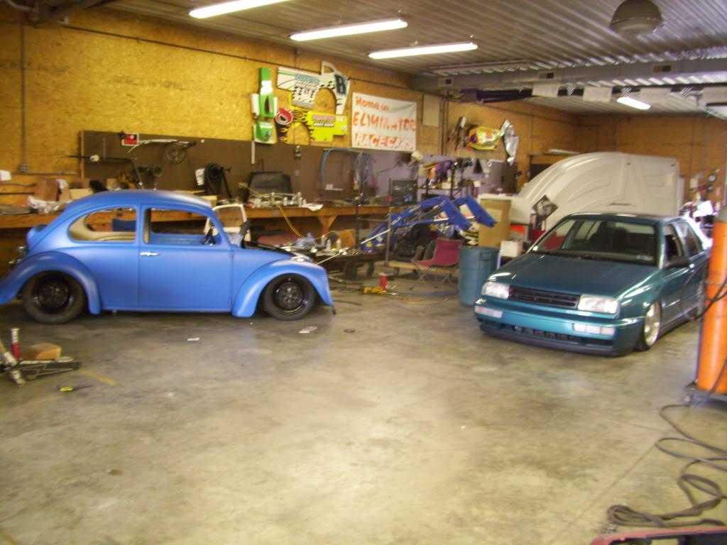
My buddy's beetle in the background.
I got this sweet new cone filter. The first one I ordered way back in June 2008 was wayyyy too small. This one is just right. K&N from Summit.
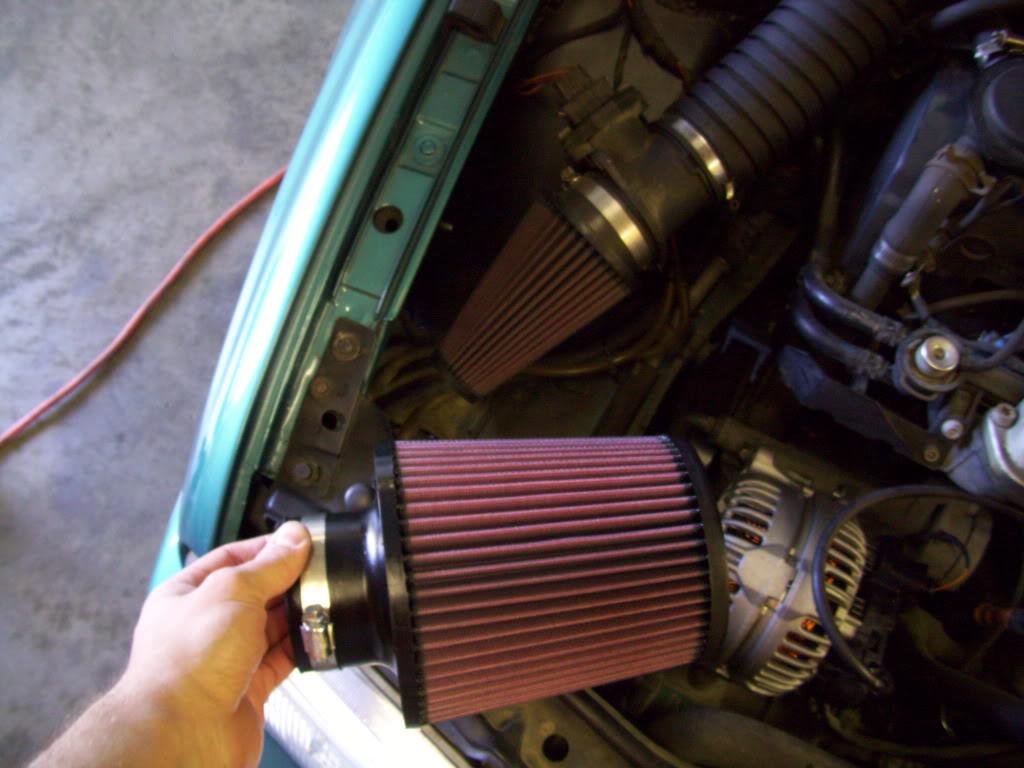
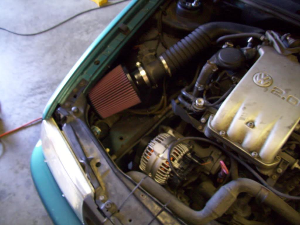
+50 horsepower, minimum.
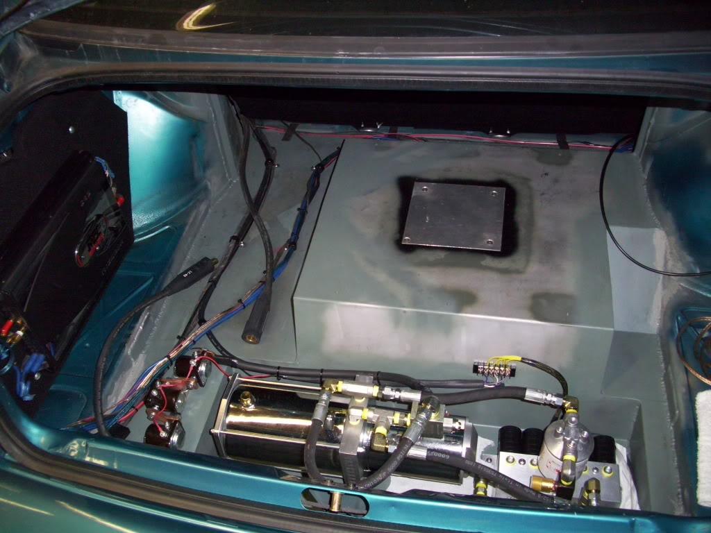
It turns out I will be driving myself to H2O, so I decided to throw this sweet stereo back in. I had my front (only) speakers hooked up to the amp back years ago, so I didn't have any tunes until I put this amp rack back in. I know I know... try to hold back your jealousy of the sweet MDF/Jigsaw fabrication I did back in 2004
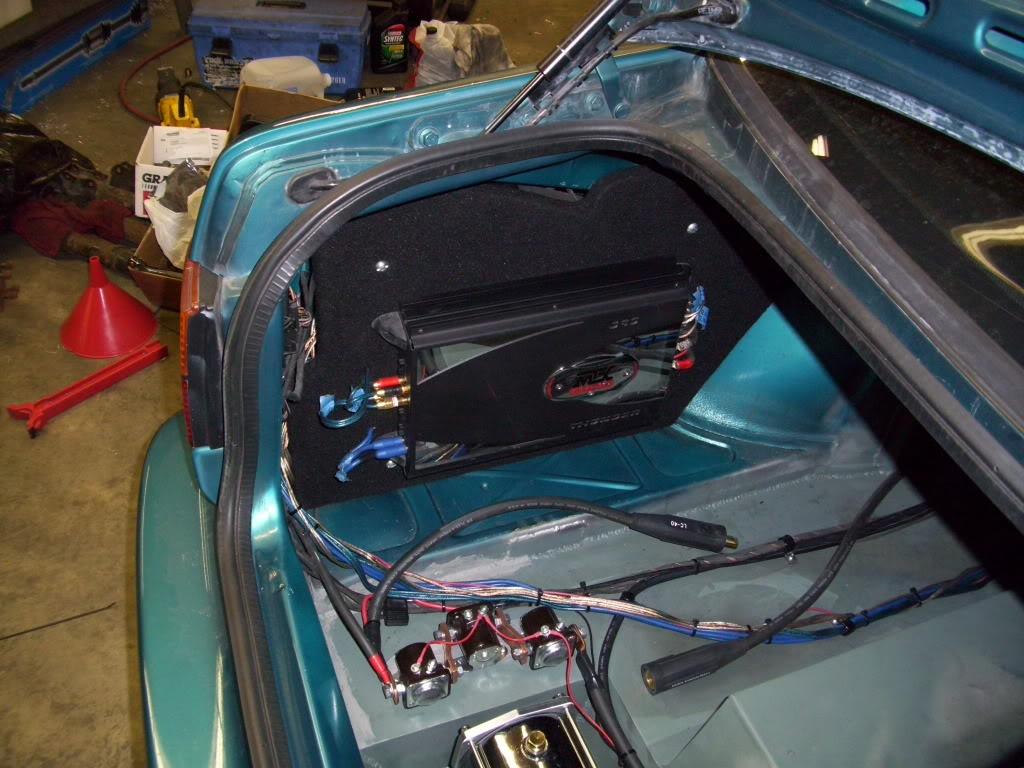
And that finishes off the trunk. Done!
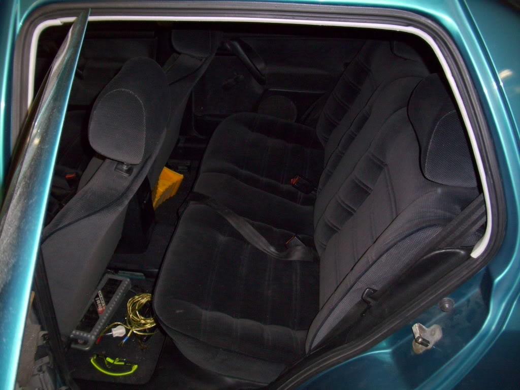
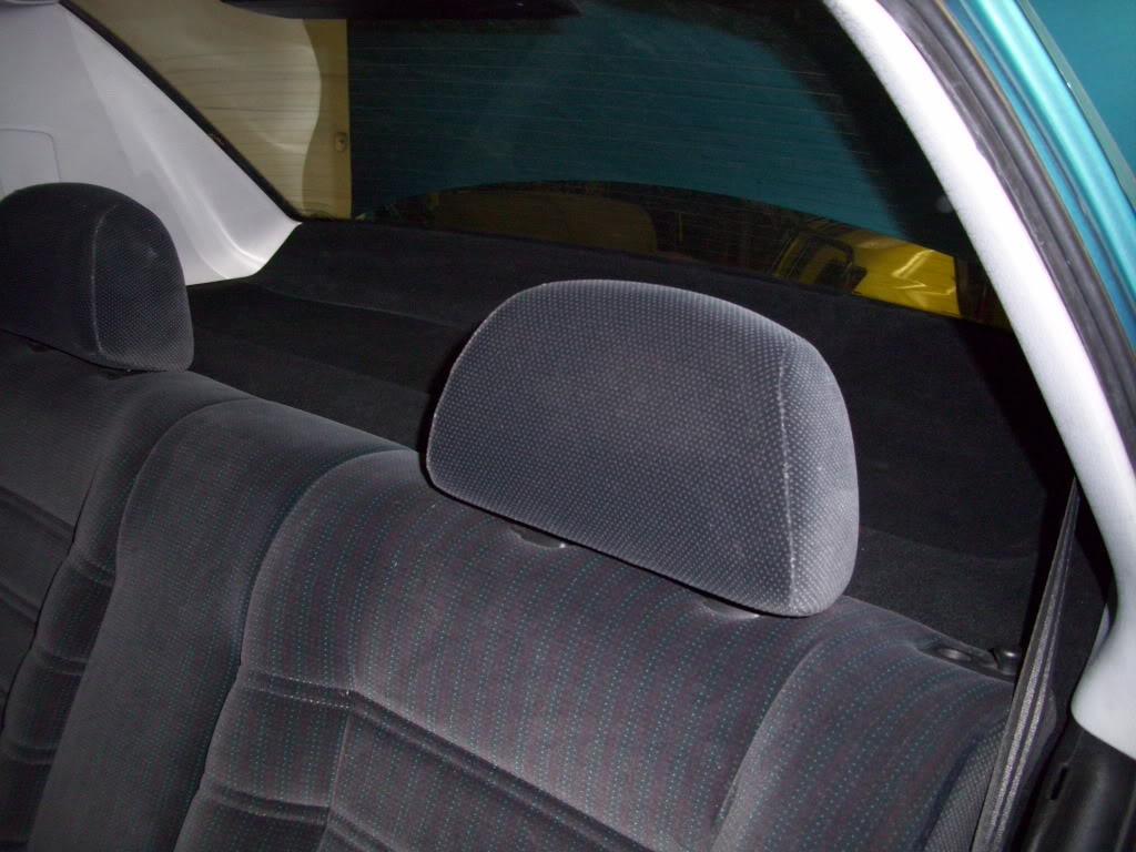
I got the rear interior all reinstalled.
At one point prior, I had my dad hook up a current probe and measure the current draw when the hydraulic pump is running. It draws 180Amps when lifting the car, so my 200A fuse was a great guess! It's a bit undersized, I should probably run a 220A or 250A, but it was all I could find on short notice.
To handle the extra strain on the electrical system, I decided to upgrade to an Optima Redtop (34R) battery. I should probably be running a dual battery setup, but it's worked well so far since I dont' play with the switches too much.
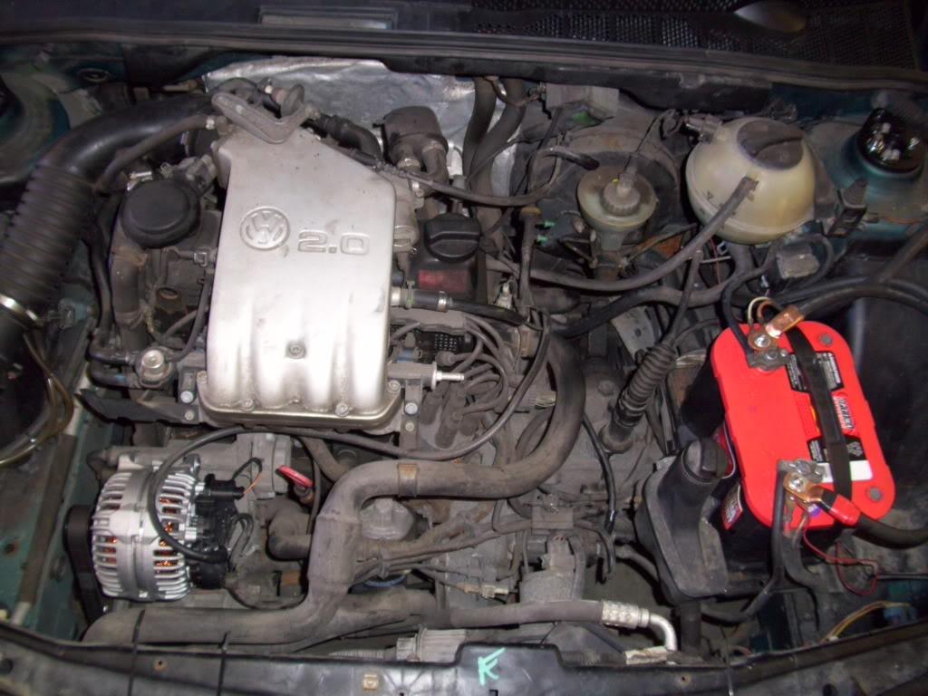
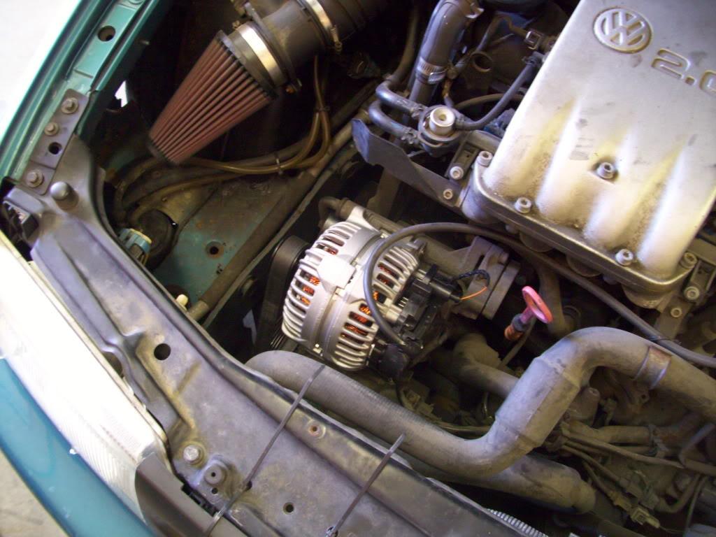
I ordered the VR6 alternator upgrade from GAP.
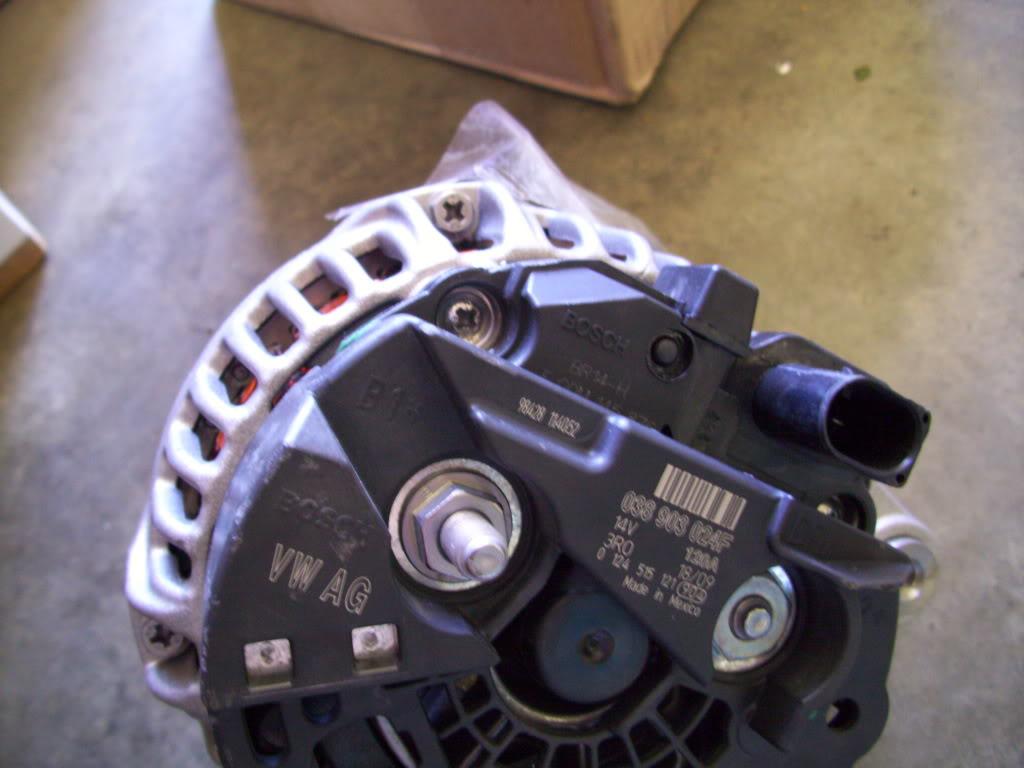
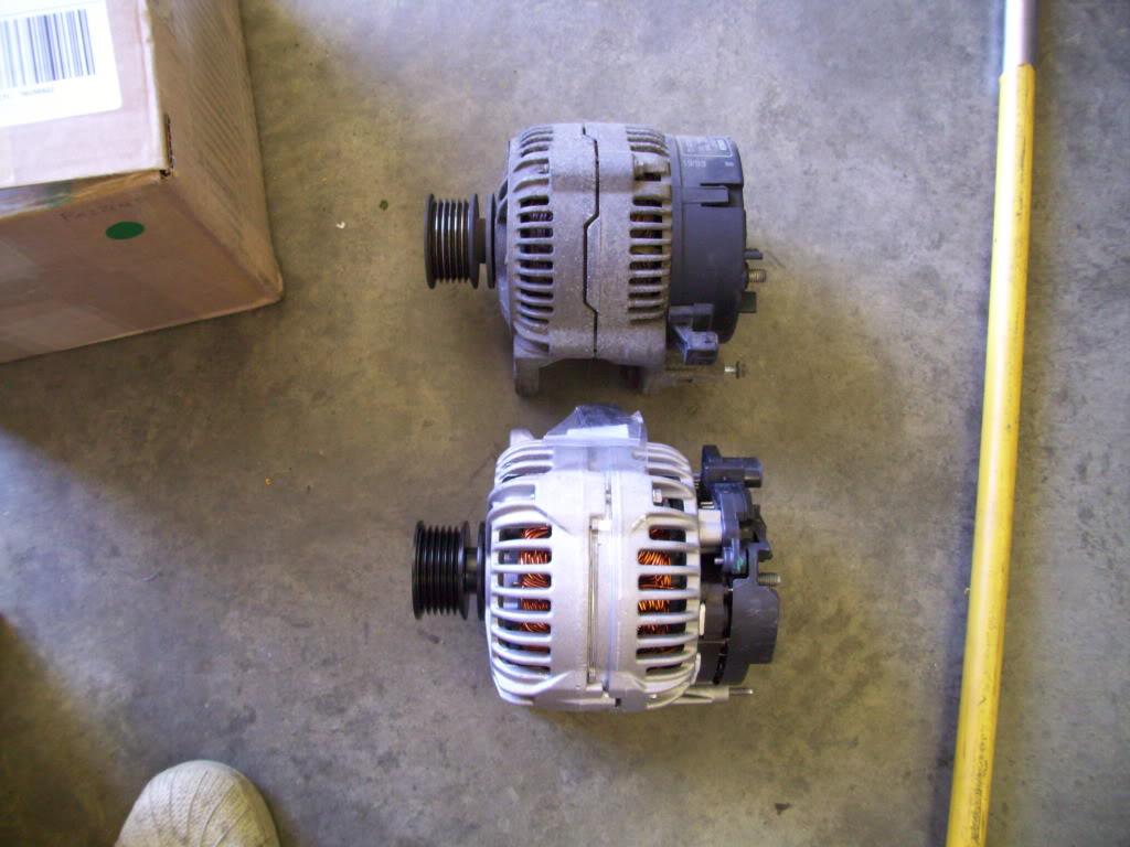
The stock alternator is 90A, the VR6 unit is 120A. I priced out some 200-400A monsters from the performance car audio scene, but decided this would be just fine. I'm not hopping like a lowrider, so my average current draw is still super low.
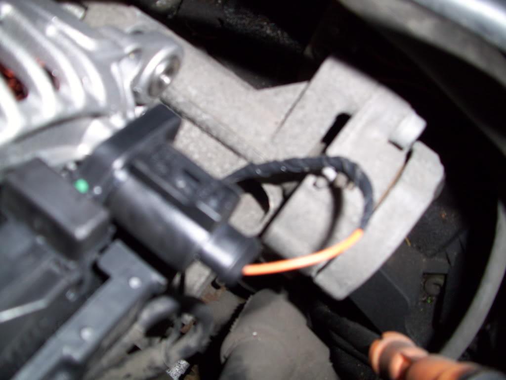
The plugs are different in the VR6 and the stock alternator, so I had to splice in the new connector.
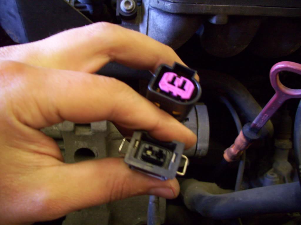
This is the only bad thing you will EVER read about GAP... I spent all day F'ing around with this F'ing plug trying to get the pins out without the proper tool. They couldn't include a $1 wire pigtail?!? I ended up taking a donor clip out of an old harness, which I smahsed the plastic connector off, then soldered it onto the old wire. Alright enough rant, GAP is still badass
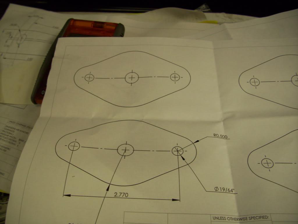
I needed to make some sort of connector/bulkhead for the fuel pump wiring, which was just going through an empty hole in the floor. I had this planned out months before, but finally got around to making the bulkhead.
I've used this method for a lot of the fabricated parts: Print a pattern, trace and cut out, clean up with a file/grinder/sander, then weld. I did this with all the strut tabs, some of the fuel cell mounts, fillerneck parts... I finally decided to take some pictures of the process.
I made a CAD model of the plate and printed it out in full-size 1:1 scale.
Traced it onto some 1/8" aluminum plate
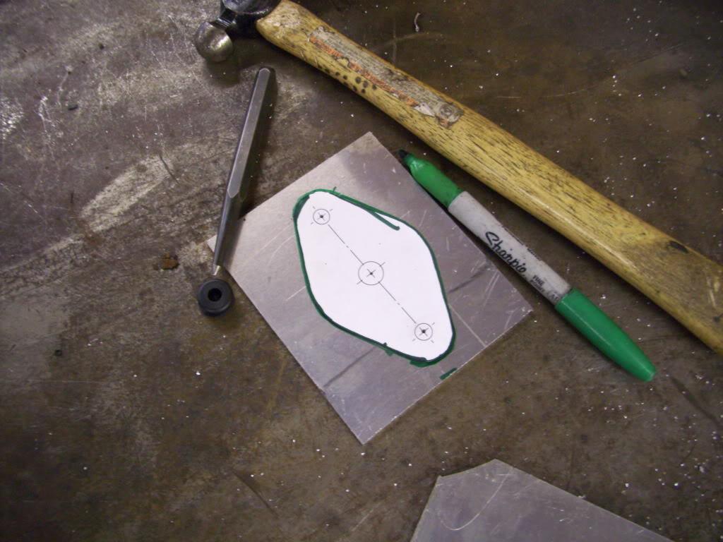
Cut it out with a jigsaw. Don't hate on those cuts.
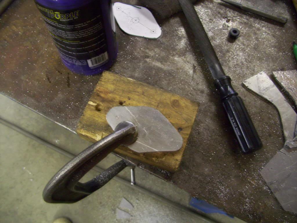
Now with this particular plate, I cut two identical plates and slotted them. You'll see why in a minute:
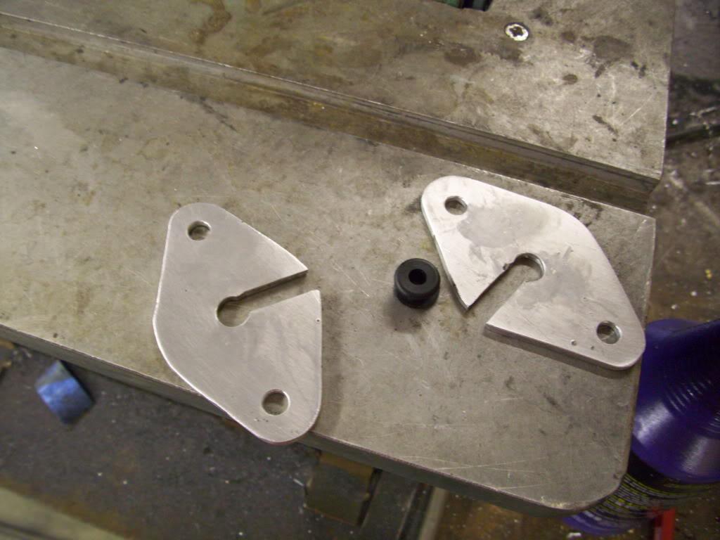
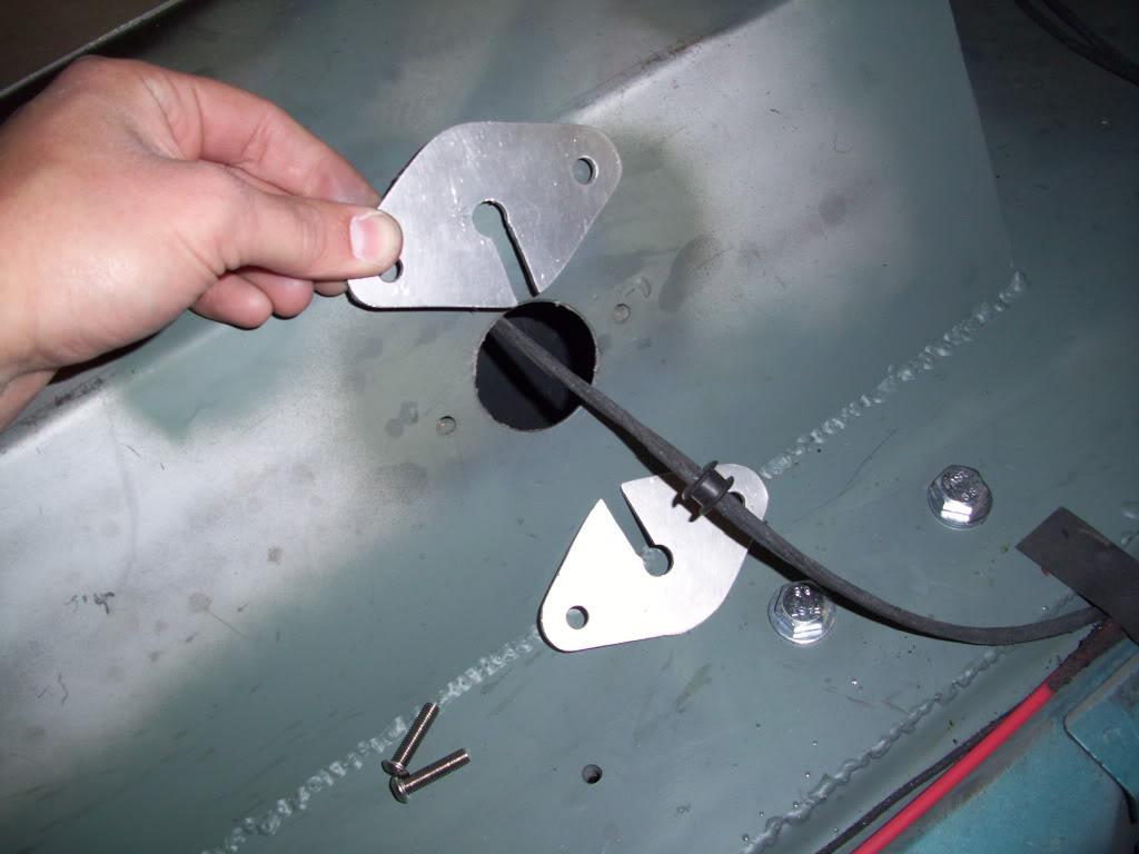
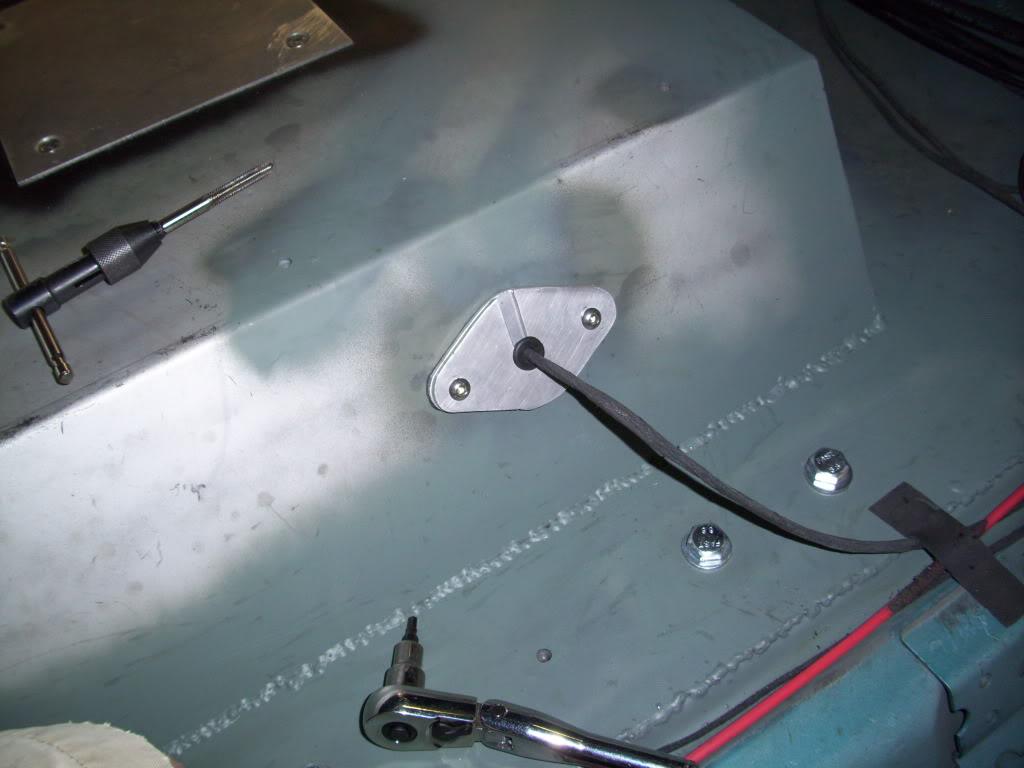
You can see the rubber grommet around the wire, which will fit snug into the holes. Using this split grommet, I can seal up the wire without removing the big fuel pump connector from the end. The connector itself barely fits through the 1-3/4" hole in the floor, but this bulkhead plate design allows me to seal it up. I even had more gasket material on the back sides (can't see from the pics) to seal it up. It's not a 100% seal, but close enough for me.
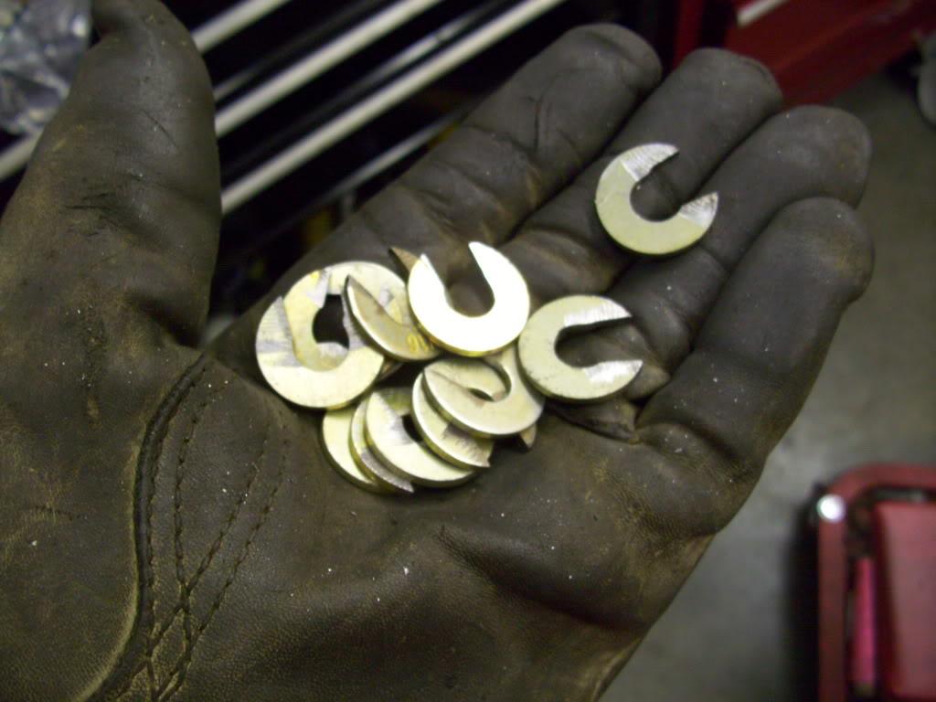
I also made all these shims to move the rear "steering rack" upward.
I didn't take any pics of this process, because it's hard to capture with pictures, but here's a brief explaination.
When you lower the front of a mk1/2/3/4, the wheels toe-out. The left wheel is steering left; the right wheel is steering right. I knew that. Since I mounted a mk3 front subframe on the rear, in reverse, I knew it would toe-in as I lowered it. In order to correct the toe-in through travel, I had to shim the "Steering rack' upward. This is possible in my rear because I don't have an engine or header or steering linkage to worry about; I can just move the rack up and should fix it.
During the initial setup, the car generated a lot of toe-in even with the 1-1/2" of travel in the hydraulics. I shimmed and shimmed, and the rack went up 1/2" and the toe change got better, but still not perfect. This can only be further corrected by building a new rear steering rack which is taller, since I'm at the limit of what I feel comfortable shimming. The car still isn't perfect; I'm not sure if anyone noticed toe-in at the rear but it's there. It's on the "fix it this winter" list
September 22, 2009
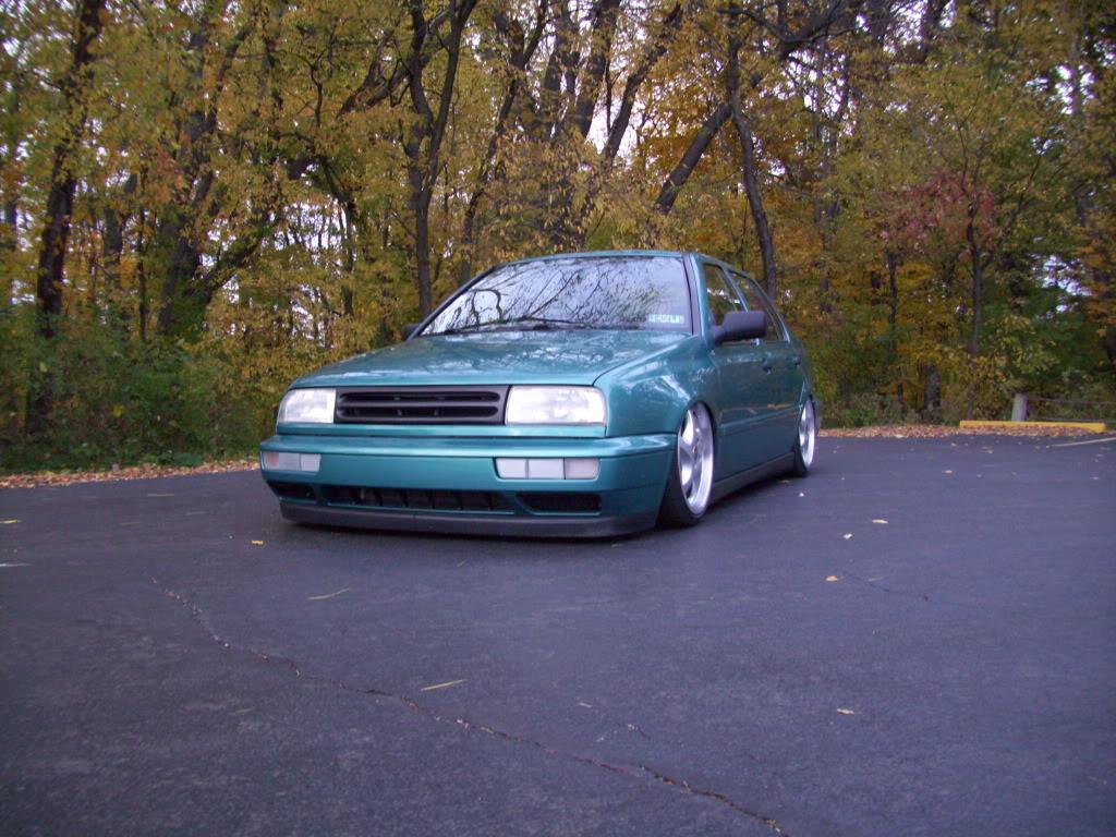
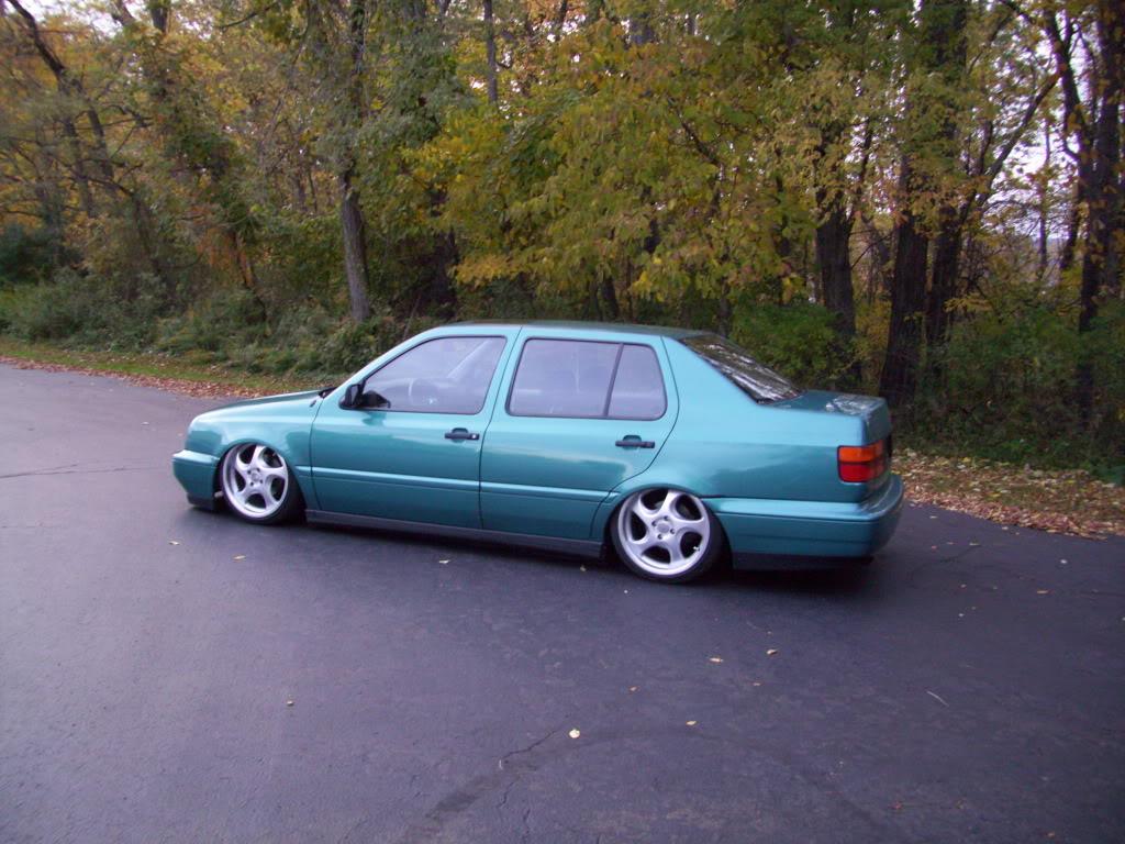
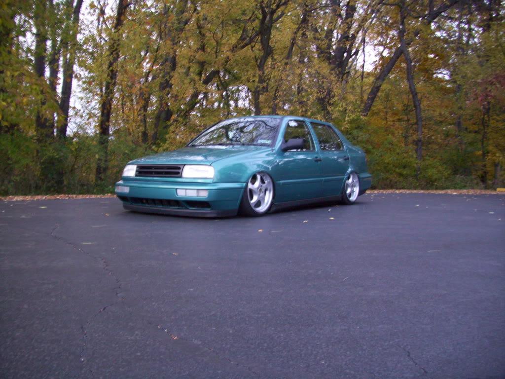
So Monday, Sept 21, I drove the car in to work and took these pictures in the back parking lot.
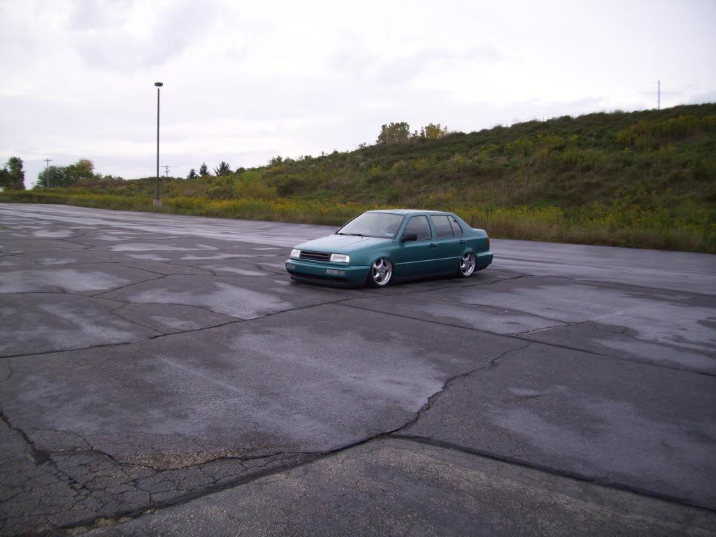
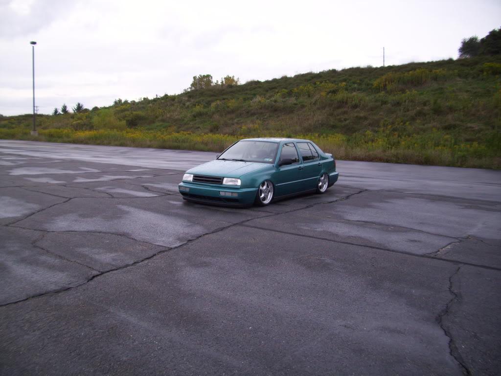
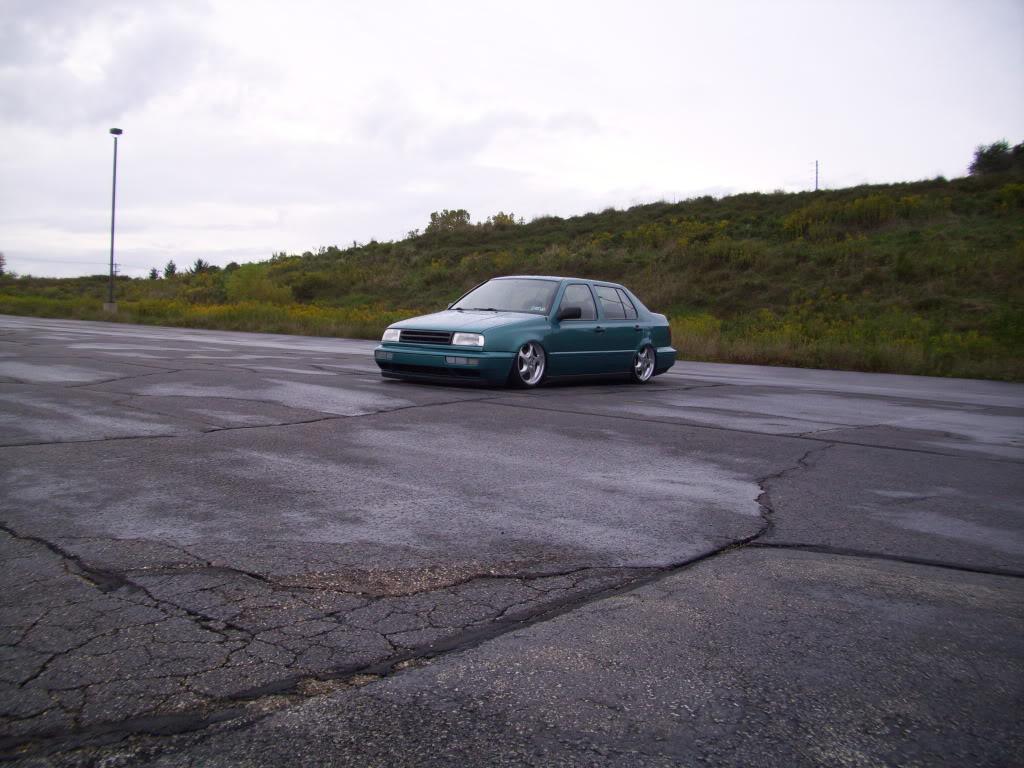
At the house on my steep hill.
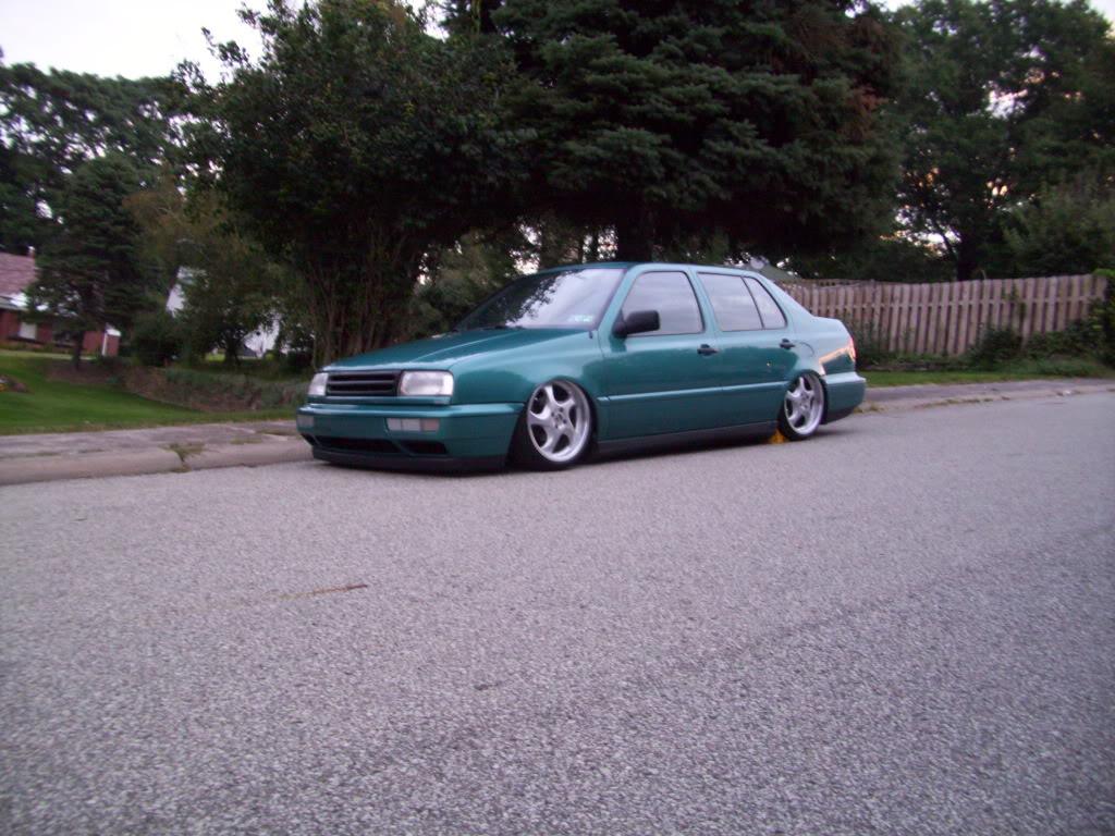
In person, the rear camber looked pretty good. In pictures, like these, I needed much more negative camber out back to correct the stance. I didnt' realize this until Tuesday evening when I uploaded these pics. I was leaving Friday for H2O. Crap.
Anyway, back to Tuesday evening.
I got the hydraulic hoses all rounted and clamped in place. Insulated zinc-plated steel clamps and self-tapping screws. I did use some zip ties around the brake lines only to keep from putting too many screws through the floor. Don't mind the rust, it's a Northeastern '94
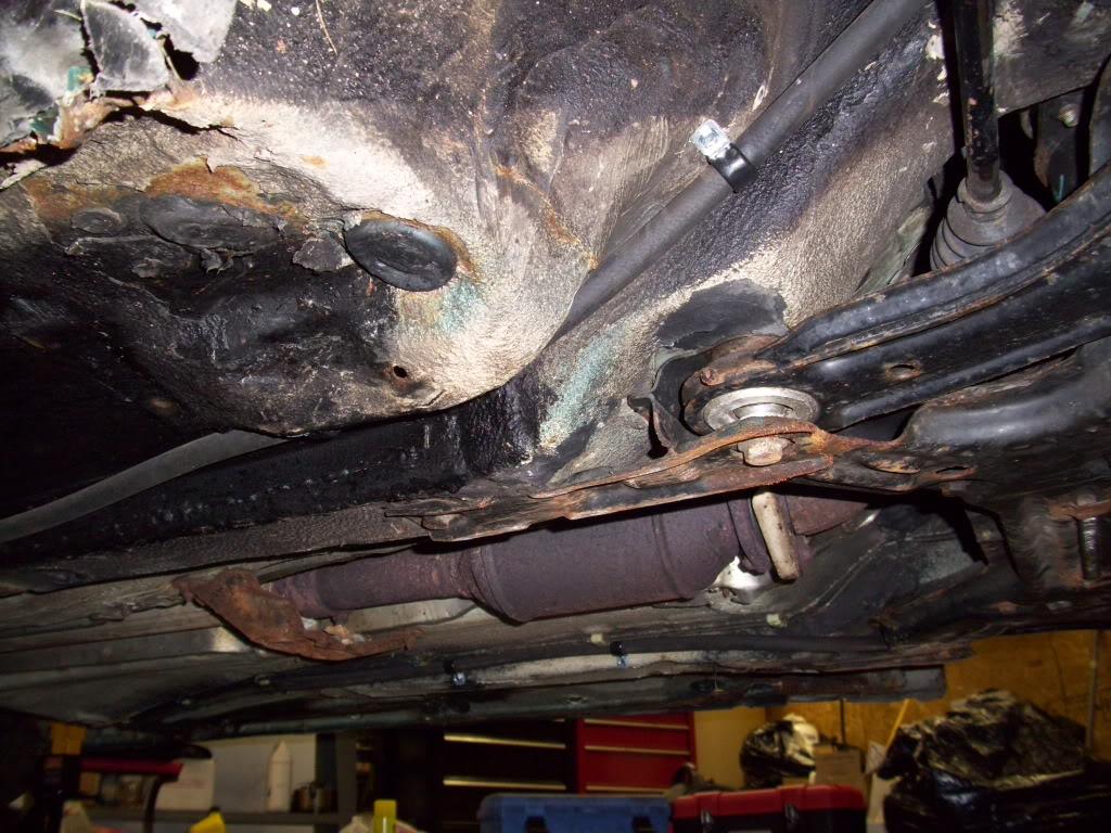
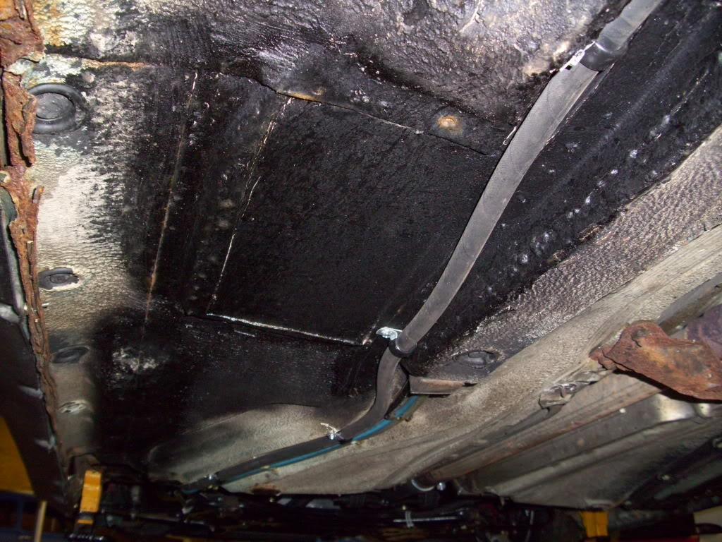
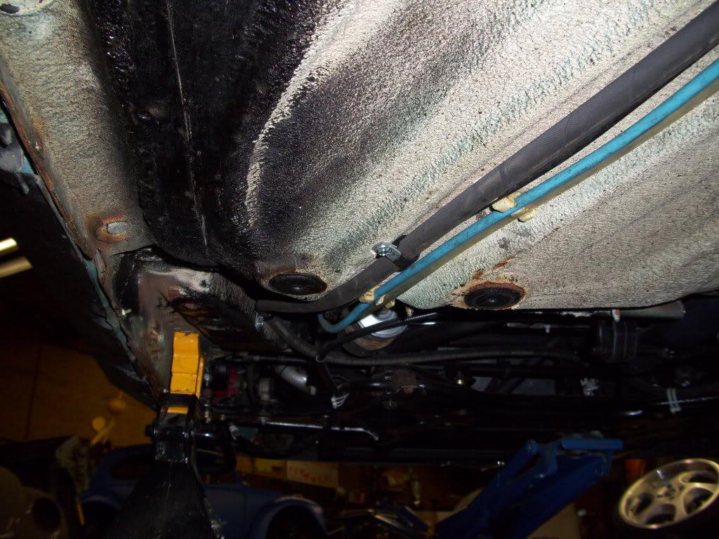
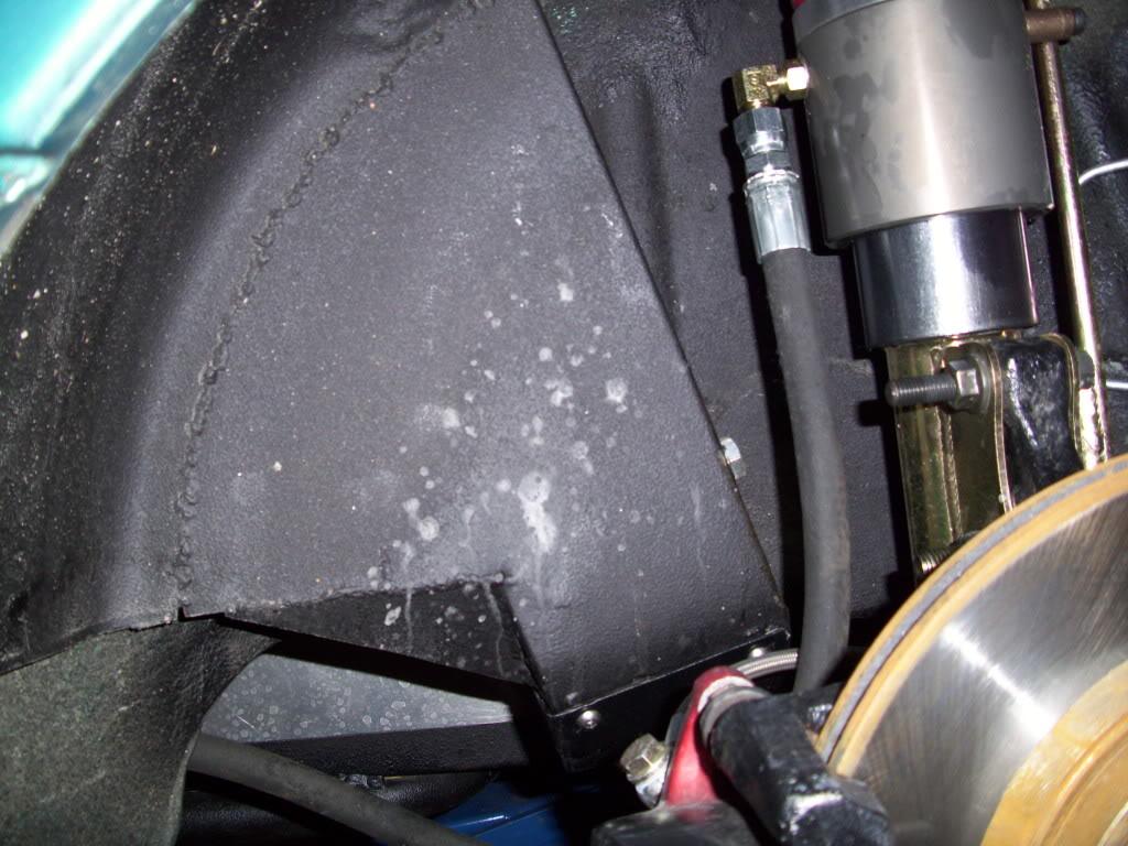
Rear cylinder routing
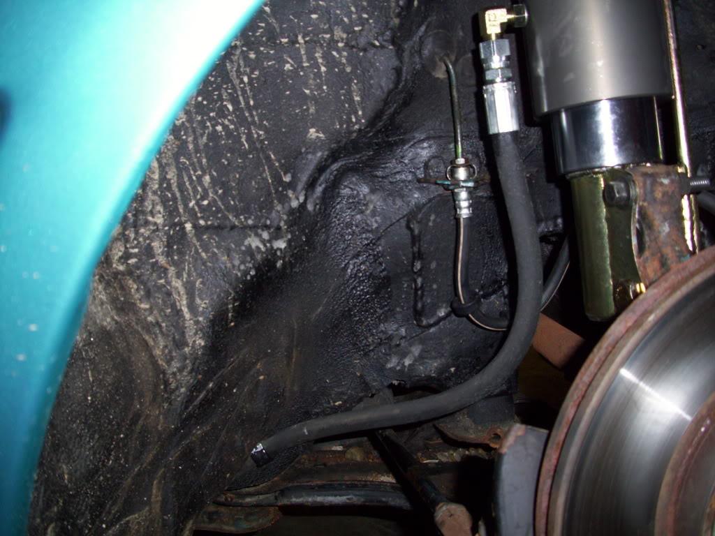
Front routing.
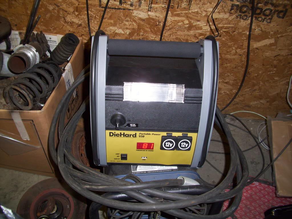
I bought a battery charger/starter just in case I ran into any trouble on the way to H2O
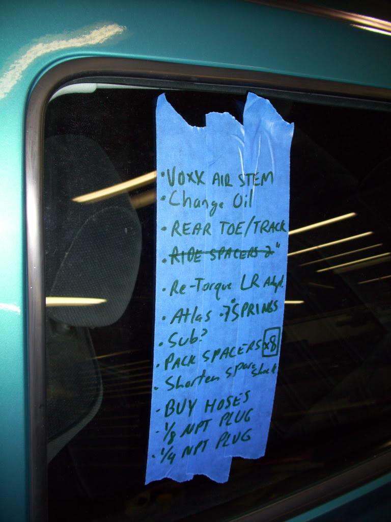
Makin' a list, checkin' it twice.
September 23, 2009
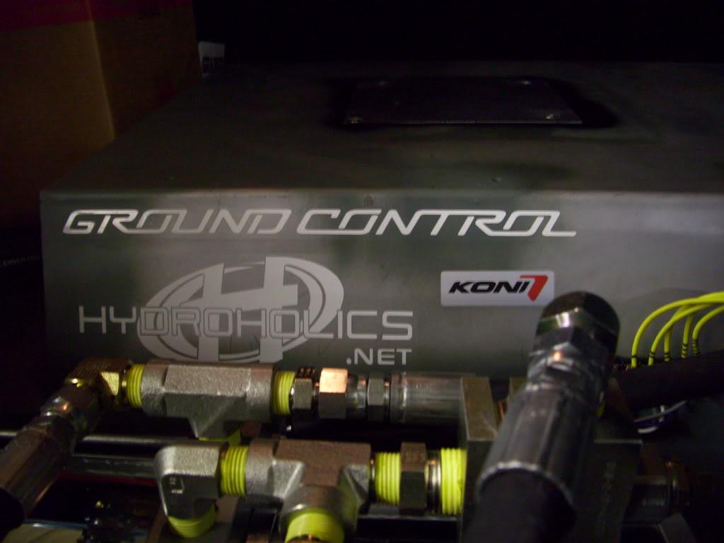
Installed some stickers. 20+ horsepower.
For those that missed: Hydroholics made the hydraulic pump and manifold. They were super helpful through the whole process and make quality stuff The springs and front camber plates are from Ground Control. I've been real impressed with their designs. I'm using Koni shocks on all 4 corners. I chose this combination of stickers in case anyone saw the trunk without me around. No single car, to date, had used components from all 3 of these companies. Keep 'em guessing
I fixed the rear camber and got the alignment all straightened out at ride height. At ride height, I am running -2º of camber at each corner and parallel toe all around. When it's down, the front toe is still parallel, about -1.75º camber all around, and still quite a bit of toe-in at the rear until I get my new rack made.
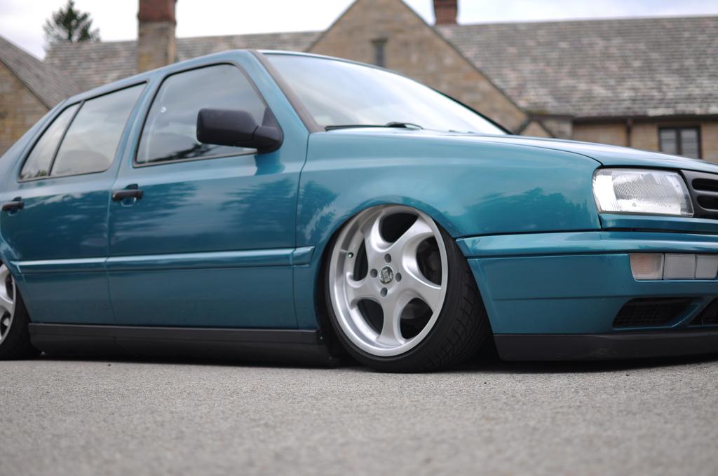
This is hard to capture photographically, but here is the final stance.
up:
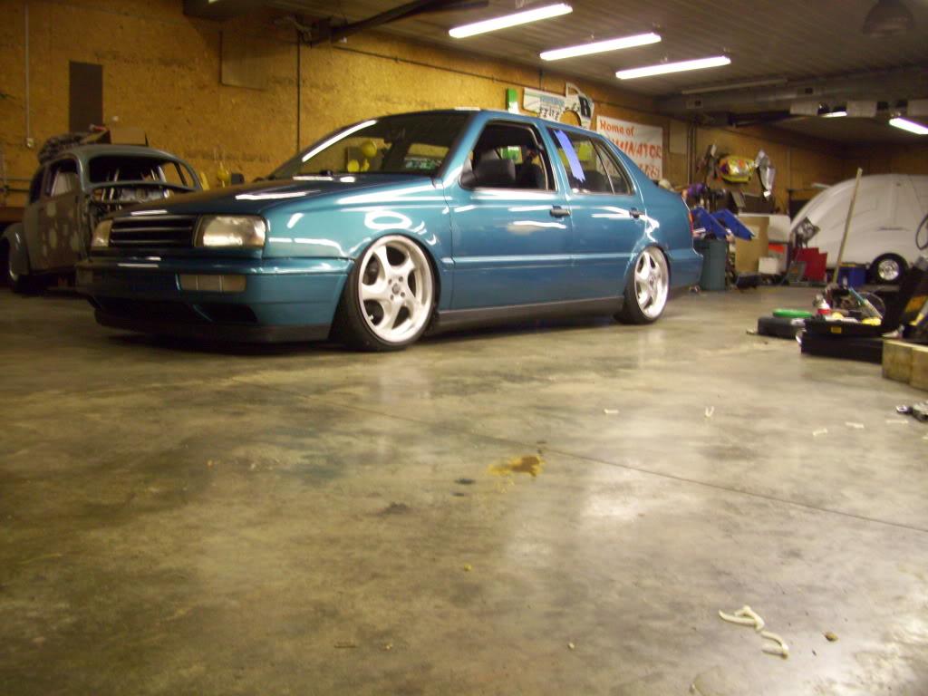
Down
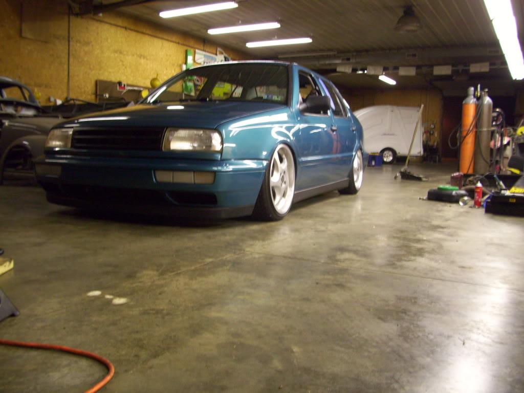
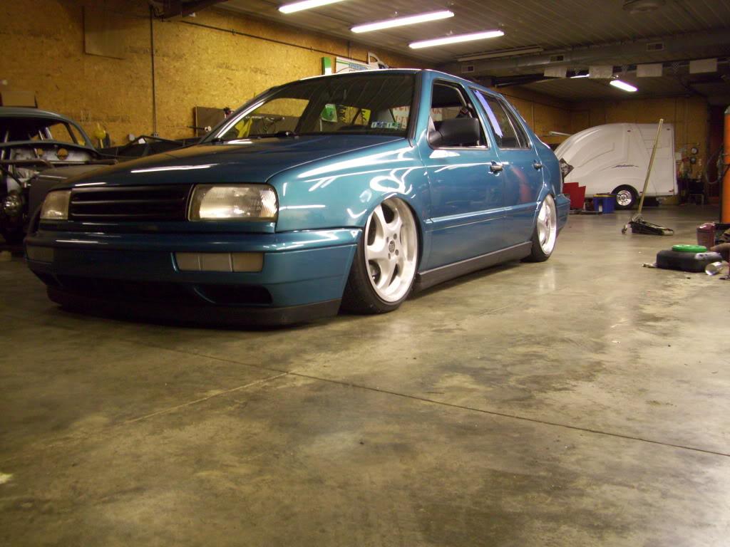
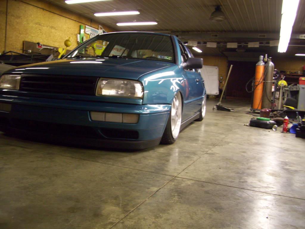
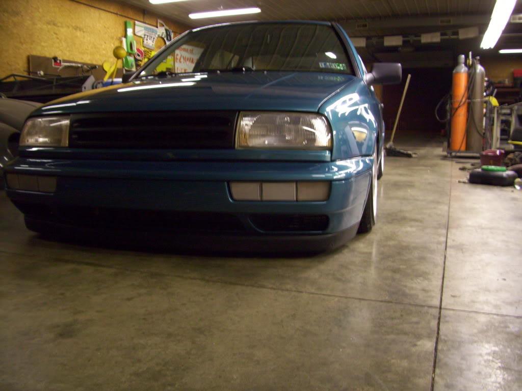
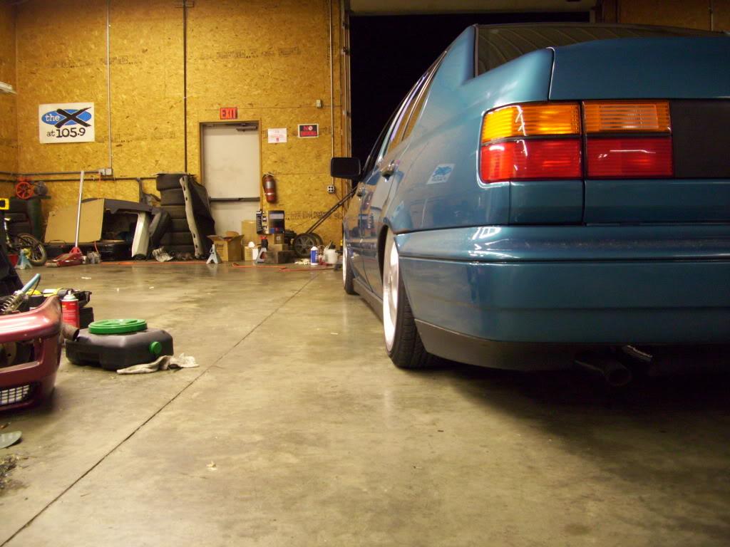
Not 100%, but that's as good as it's gonna get!!!
September 25, 2009
On the road.
H2O is less than 12 hours away.
Got on the PA turnpike, headed East.
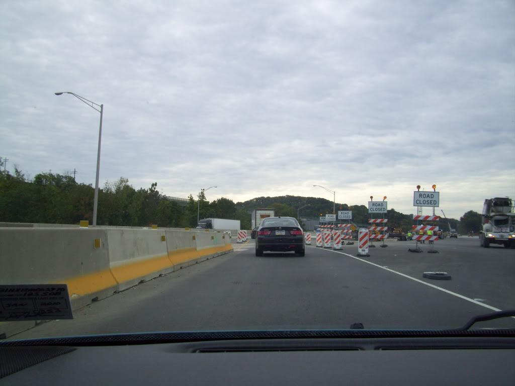
Next stop: Baltimore, for dinner at my Uncles.
Next Next stop: H2O International 2009 Can't F**king wait!!
H2O.
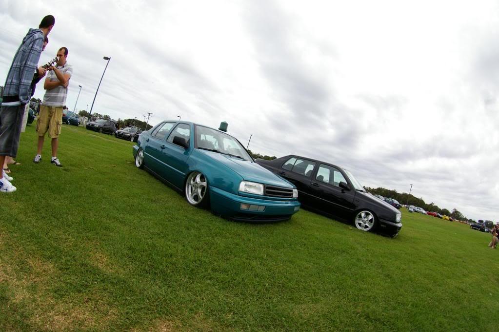
Absolute awesome time. I met a ton of awesome people, explained the suspension about 1000 times, ate some good food, saw a lot of amazing cars, met more awesome people.... I can't type enough words to describe how perfect the weekend was. It felt so good to drive the car, to get it out in the open. Two long years of cutting, welding, machining, and planning had finally reached the climax.
Thanks to Livinzlyfe for these pics:
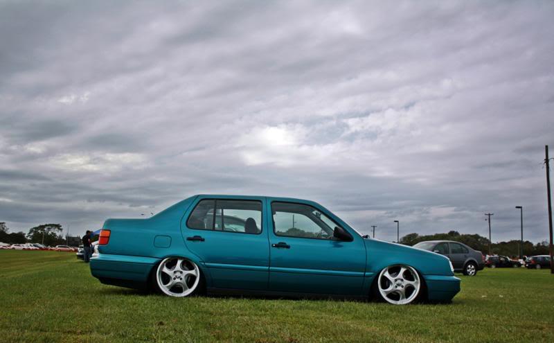
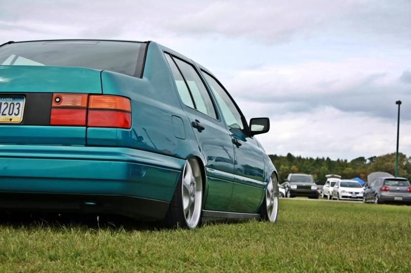
And Neb
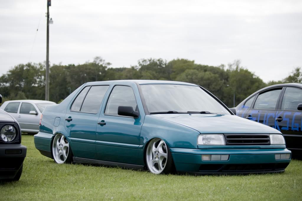
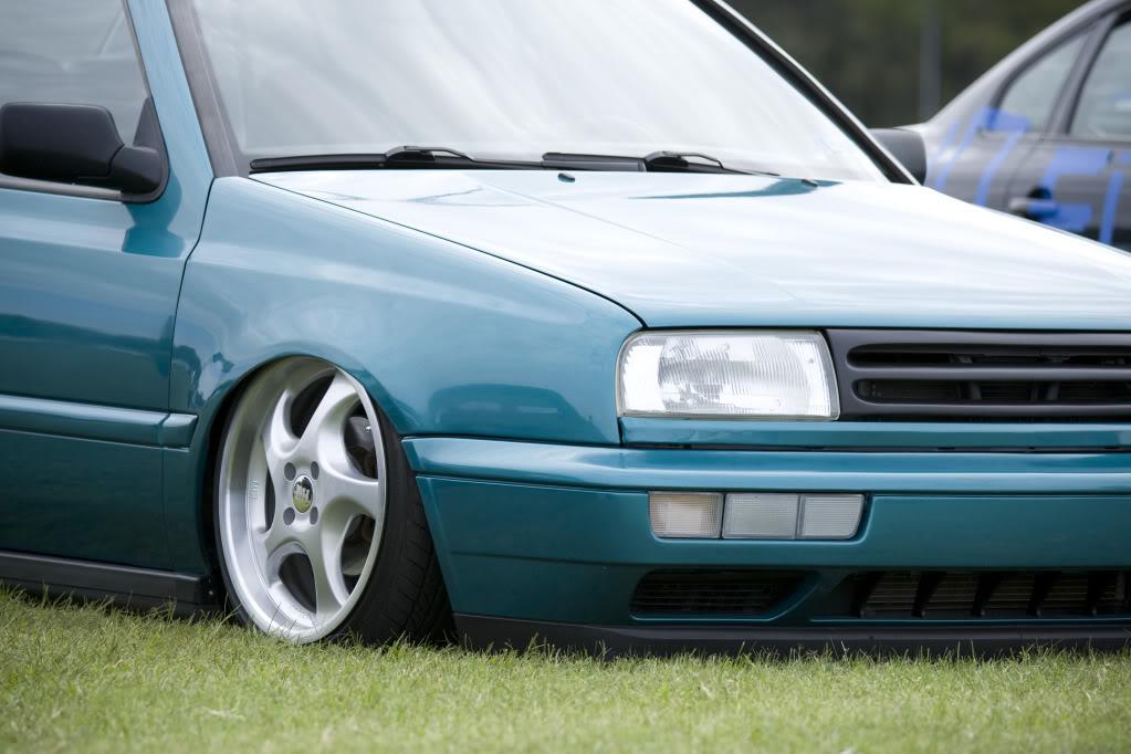
Shannon Hamilton snapped this pic of the car all the way up. This is the driving height. +1.5" above ground
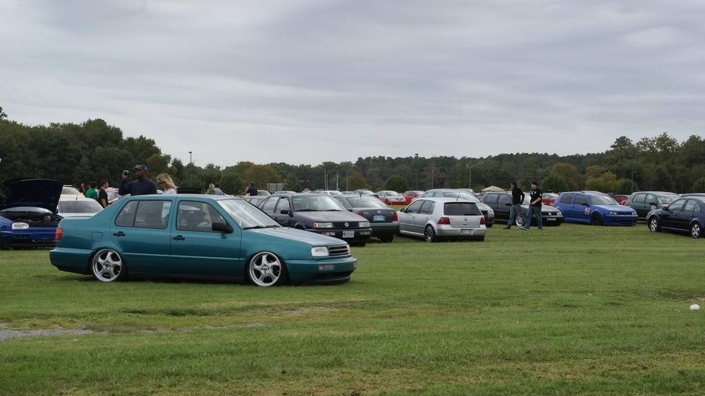
ric Juers (forget your screenname) took some pics with me and Paul Wall. I have to thank Paul, he's known about this from the beginning. I remember him listening to my crazy ideas, and always encouraged me to just go for it. He was also cool about keeping it quiet, no matter how many pics I showed. He finally got to see it in the metal! Thanks man
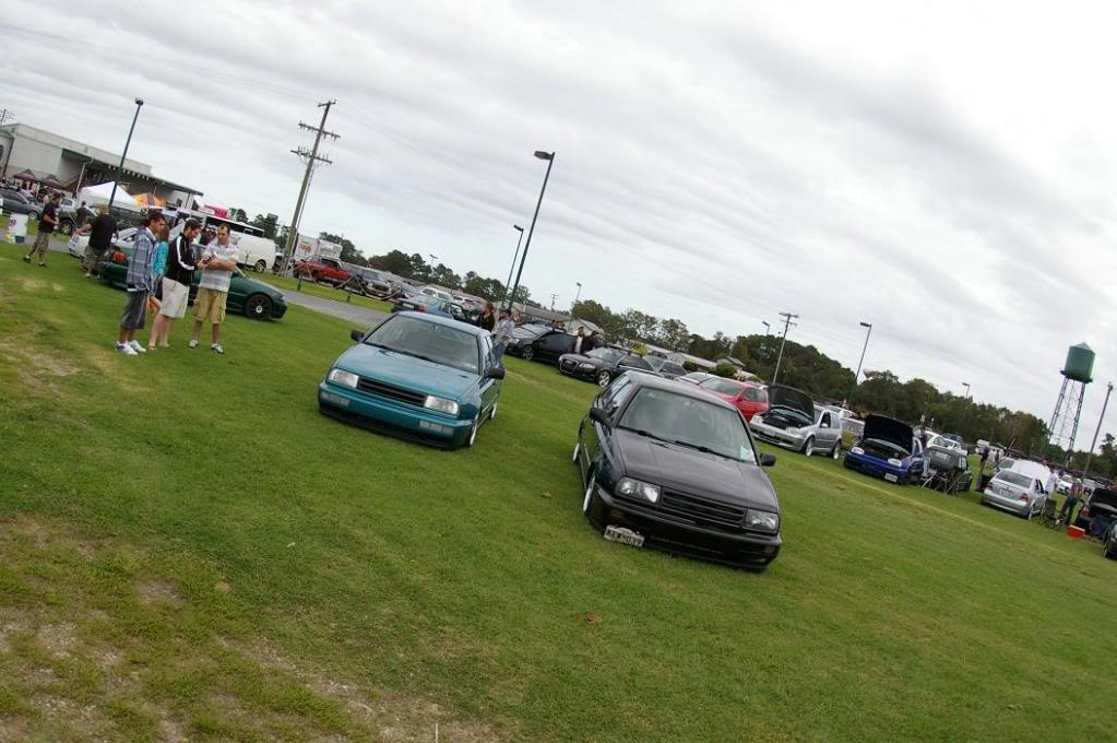
Eric also snapped some rollers on the strip. Thanks man!
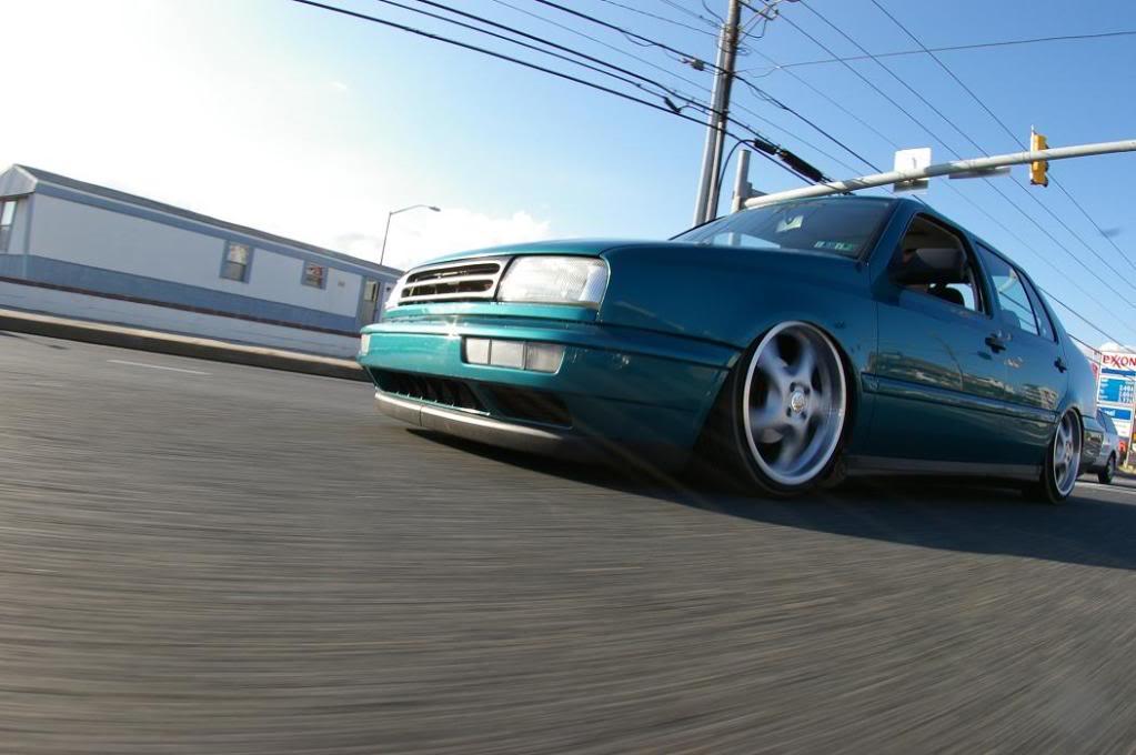
I dragged the hell out of the car all weekend! I built this thing to drag and lay on the floor, and boy I did!!
Limbo contest at Air Affair:
Brent, OnelowCabriO, shot this vid on 37th street by the Castle. Thanks man!
http://s455.photobucket.com/user/afa..._0464.flv.html
Thanks to everyone I met at H2O for all the good words; It was great to meet you all! It was an awesome weekend.
I drove home Monday morning, with New2 and his buddy and his buddy's girlfriend. He snapped this final rolling shot just before we parted ways outside of Pittsburgh.
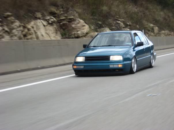
Zero problems all the way there; all the way back; the whole time there. 900 miles without an issue; luck was on my side!
I'll be adding more finished pics in the next few days, but until then, this concludes the build of my Jetta.
Thanks for listening
-Anthony
October 07, 2009
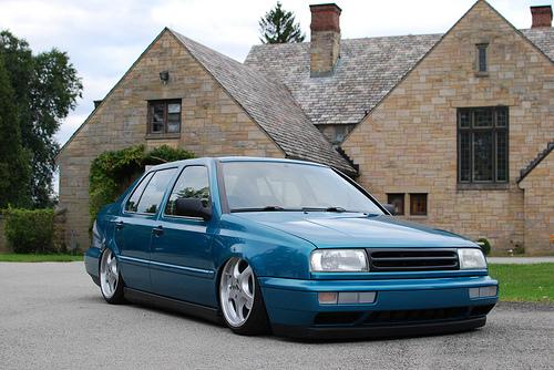
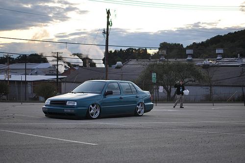
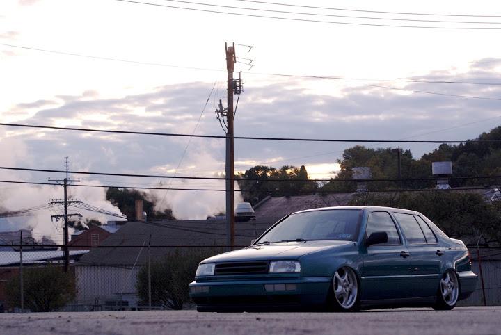
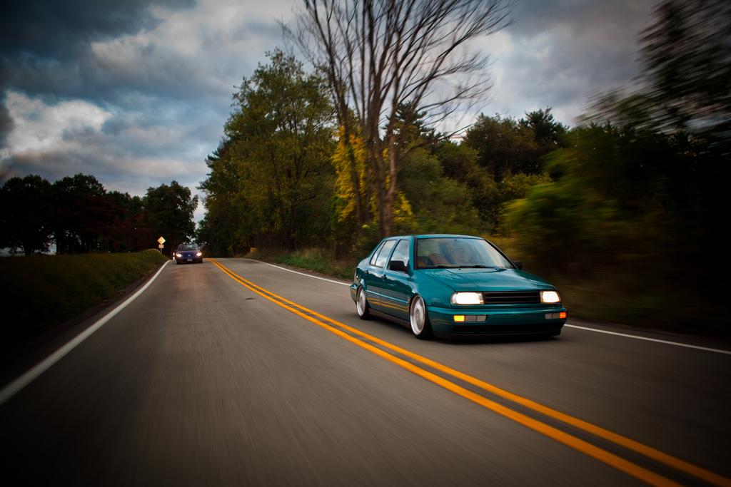
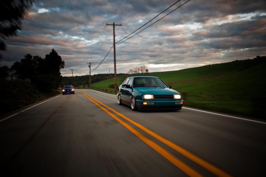
I went to a local show this weekend, Oktoberfest, and a few of my friends came out. They're all really into photography and have some nice equipment, so I figured I would share some of their pics.
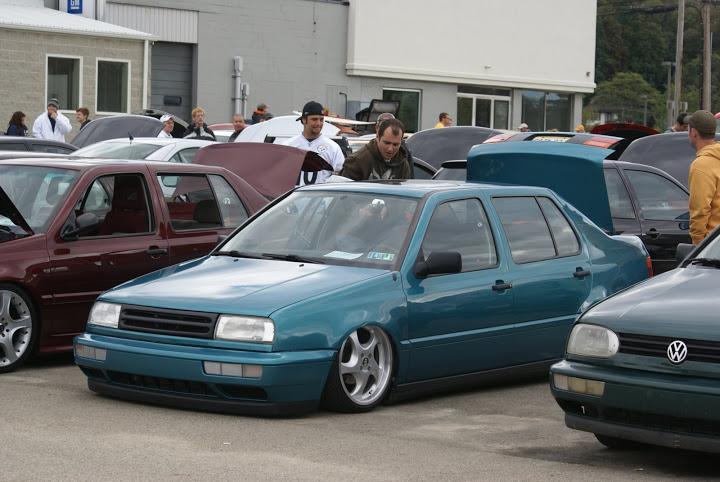
Jimmy shot these after the show

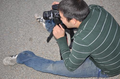
We found this cool location to do a few photos. Papparazi in full effect
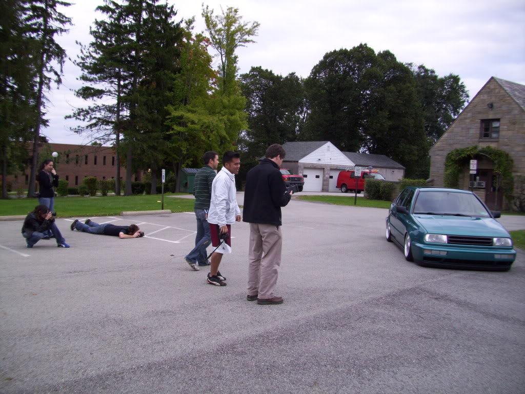
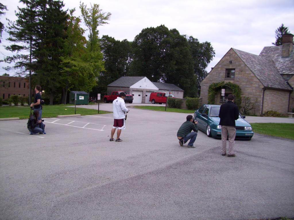
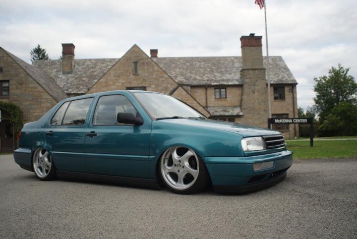
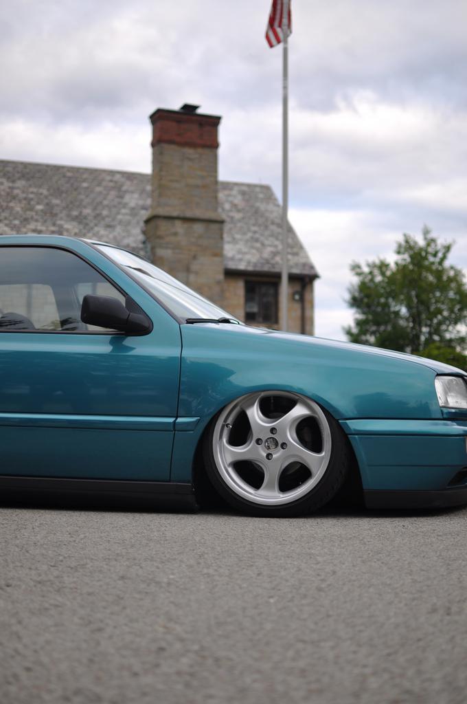
Ian, the master at work.
Rolling again, courtesy of Nicole

Found another sweet location. This is Hugh working the flash for Ian.
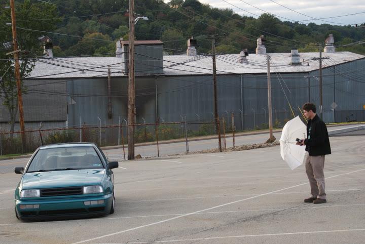
Ian, ready for some rolling shots
Ian's photos.
October 17, 2009
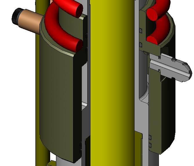
As promised, here are some 3D model views of the assembly. The cutaway views show a little bit more about how it works. The Koni housing is the yellow part, I didn't model the internals of it so it's left uncut in the cutaway views.
Here is the full assembly; this is a rear strut. All views are shown at about half travel.
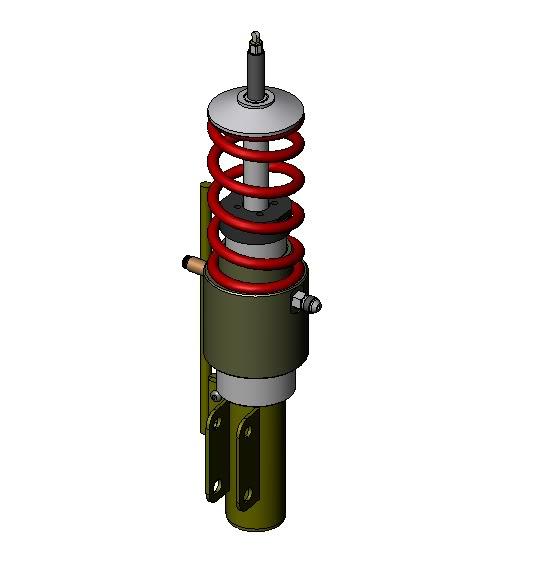
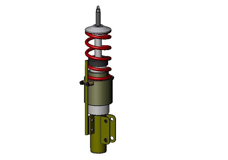
Cutaway view. This shows the seals and hydraulic fluid inlet, as well as the assembly of each piece.
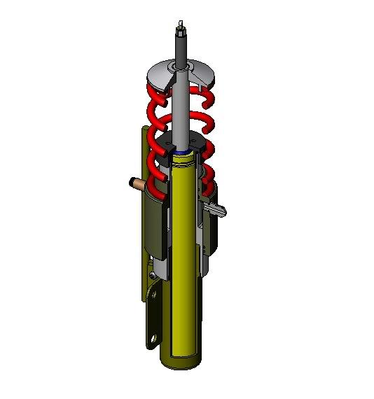
Here is a closeup of the seals and their location. There are 4 o-rings; 2 are necessary for sealing then the other 2 are just there as backup. There are dozens of different ways to seal hydraulic cylinders, and I have a dozen reasons for choosing this exact configuration, which I'm not sure I want to share right now. If anyone really wants to know, feel free to ask.
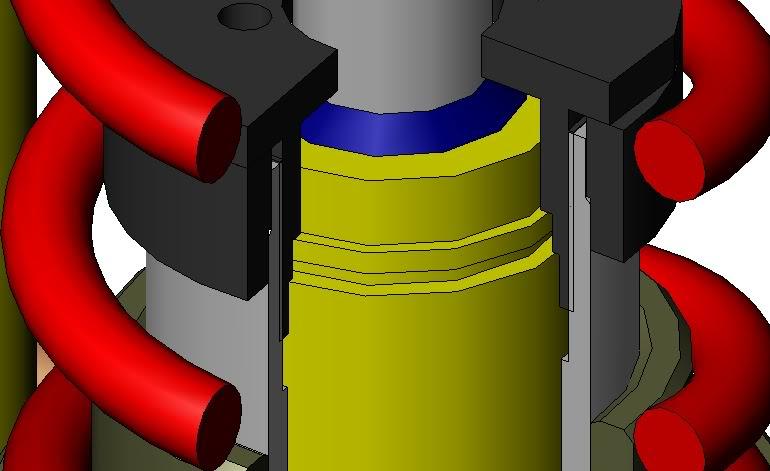
Here is a closeup of the threaded cap that holds the insert down into the housing.
Here is a closeup of the lower threads, where the lower half of the strut screws into the cylinder. This was done to create a modular design. The piston and hydraulic assembly could be used in any coil-over-shock car just by remaking the lower half with whatever mounts are necessary. This was originally done because I wanted to use the same hydraulic parts on all 4 corners, and the original plan was to have strut front and shock rear - the stock configuration.
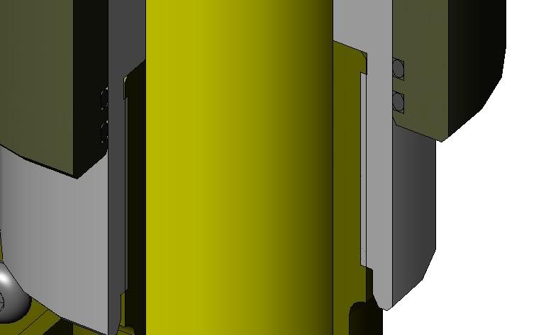
Here is a little better view of the hydraulic fitting inlet. This also gives an idea of how the piston actually works with the stepped bore. This creates a donut-shaped piston so it can be hollow and fit around the shock.
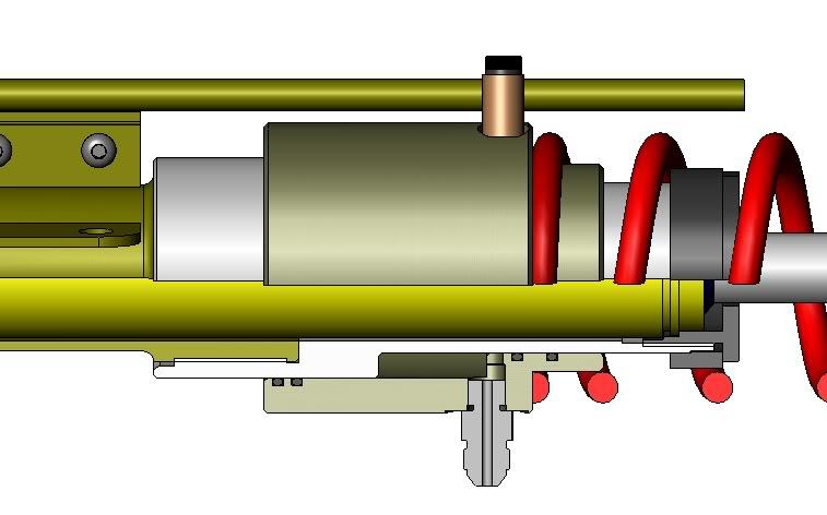
October 19, 2009
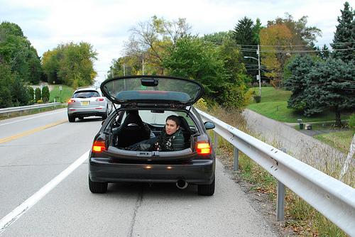
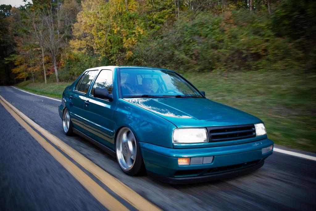
Here are some new shots courtesy of my buddy Ian Norman, more of his work is back on page 9. We went for a cruise this past Sunday through Pittsburgh's South Park. The Camaro is my Uncle's, the GLI belongs to my good friend Chris (Stallion). The photos were taken out the back of Chris' wife's Santa Fe... Ian was just hanging out the hatch and we were cruising at ~15-20mph through the park. It was a pretty good time, the scenery was awesome! We got some more stills too, I'll just share a few for now.




October 22, 2009
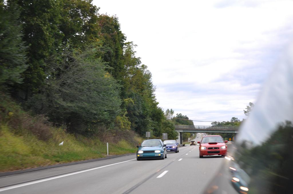
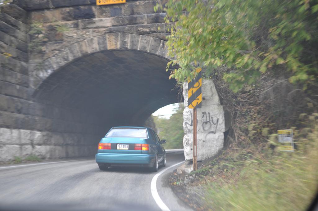
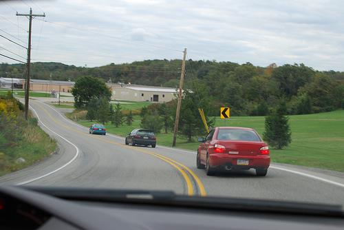
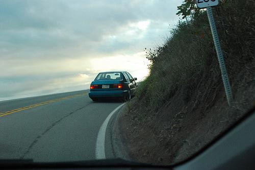
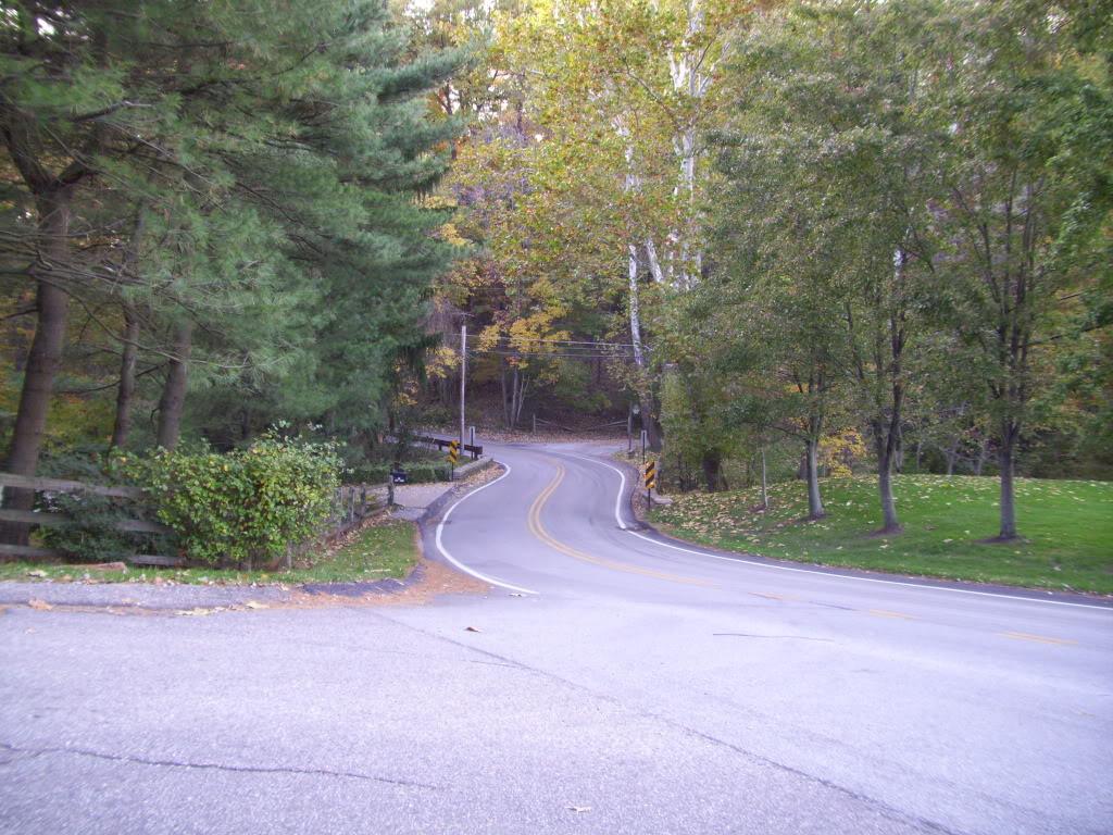
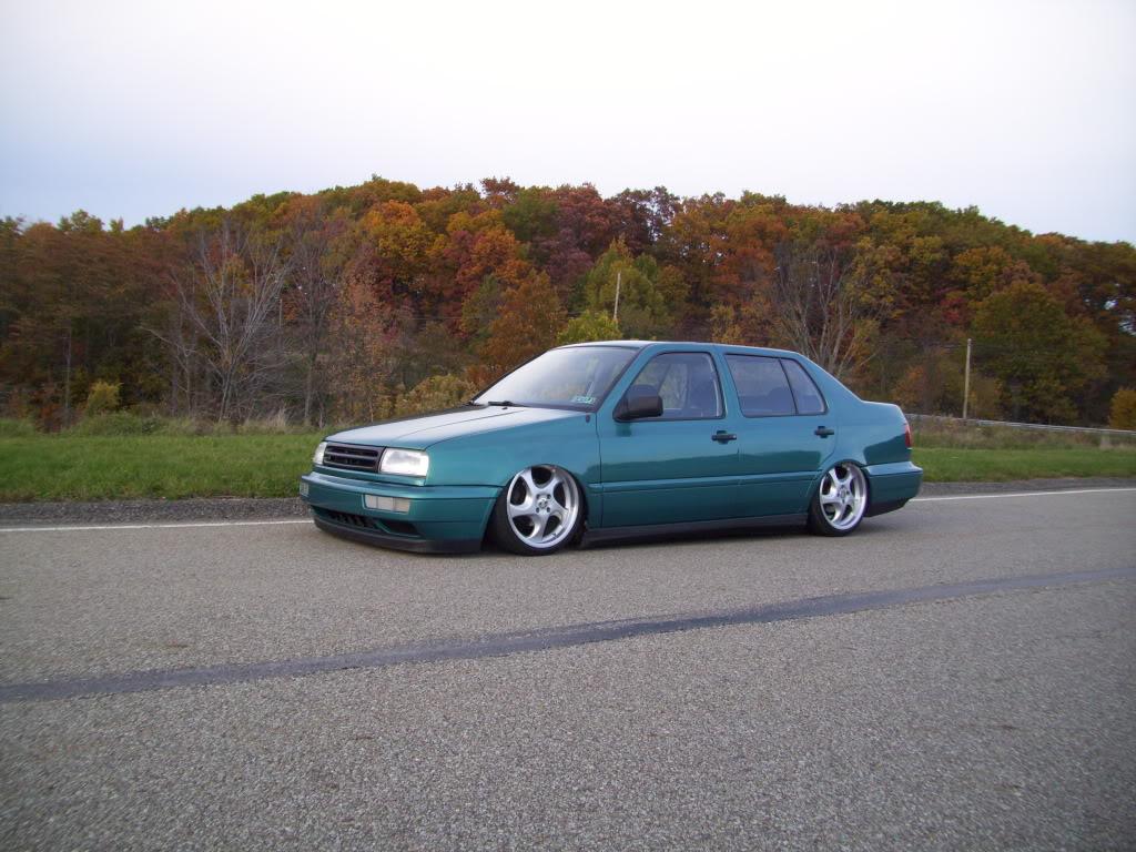
took the long way home from work today and went for a little cruise. Last summer they were doing construction on the highway, so I drove these roads every day in my mk5 coming home from work. It was about 15 extra miles, but a lot more fun than construction traffic! I finally remembered my camera and took a few pictures of the route, and stopped for a few of the Jetta.
A sign of good things to come

Stopped for some pictures. My photos look especially terrible now after seeing proper shots of the car. My Kodak point-n-shoot isn't cutting it!
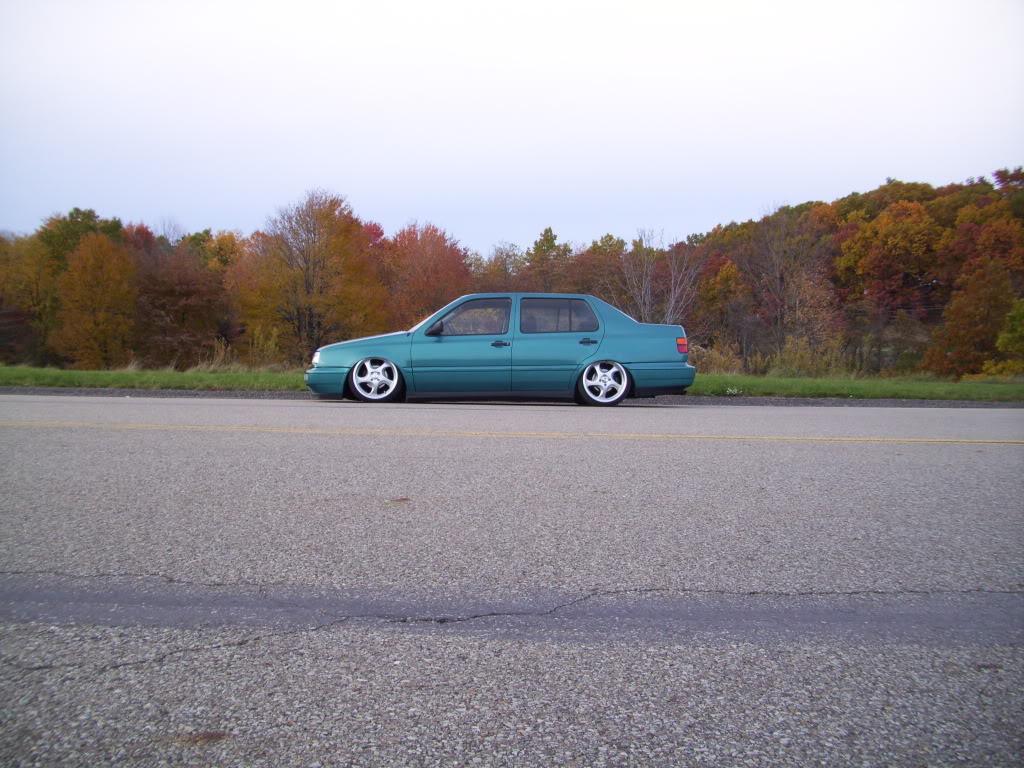
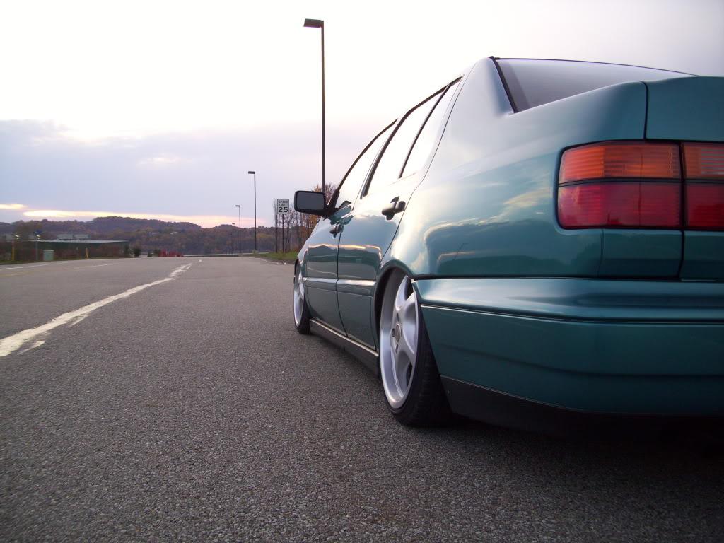
cruised some more
This one is a steep downhill ess

I wish I could capture this better, but this series is a lot of fun! This picture was taken from the end of a long downhill left-hand sweeper, which leads into this section - note there isn't a stop sign either. Elevation change and great visibility too!
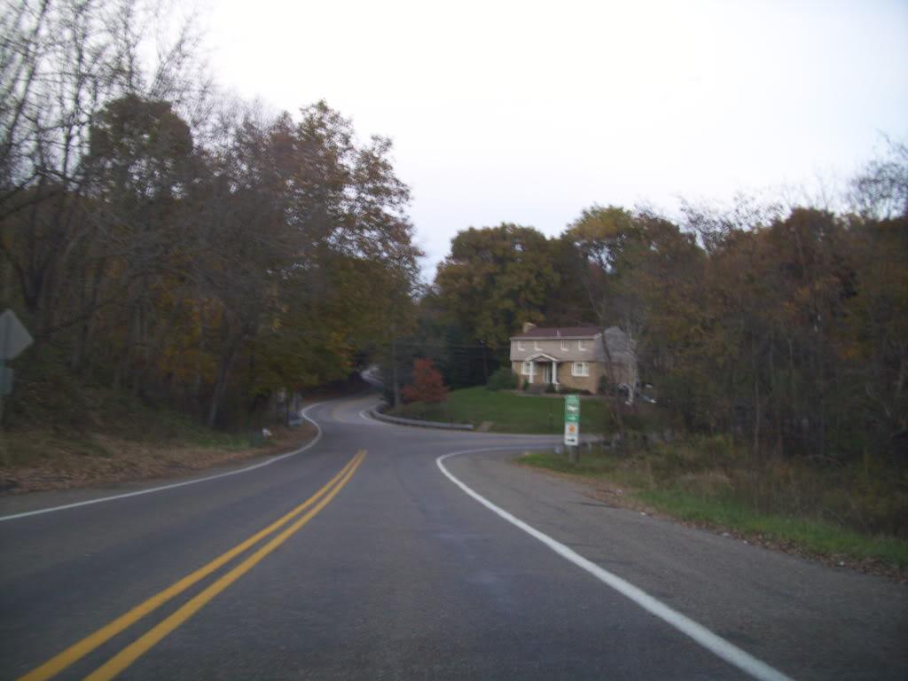
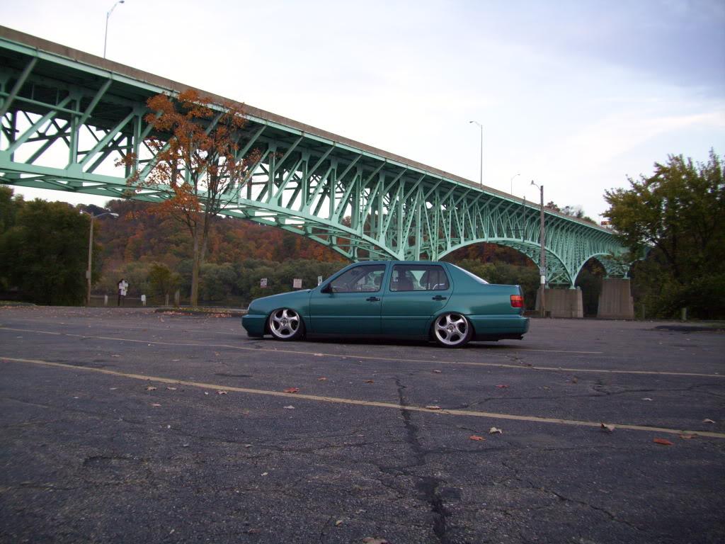
Over the Allegheny River. I cross this bridge at least twice a day, it's easy to take the view for granted. It's not as blurry in real life.

Stopped for a couple more, but it was getting dark and these ones didn't turn out so great.
I put the beast back in its cage.
October 25, 2009
More pics from today
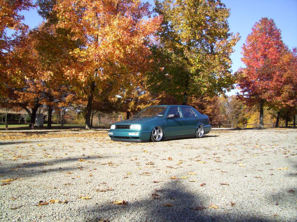
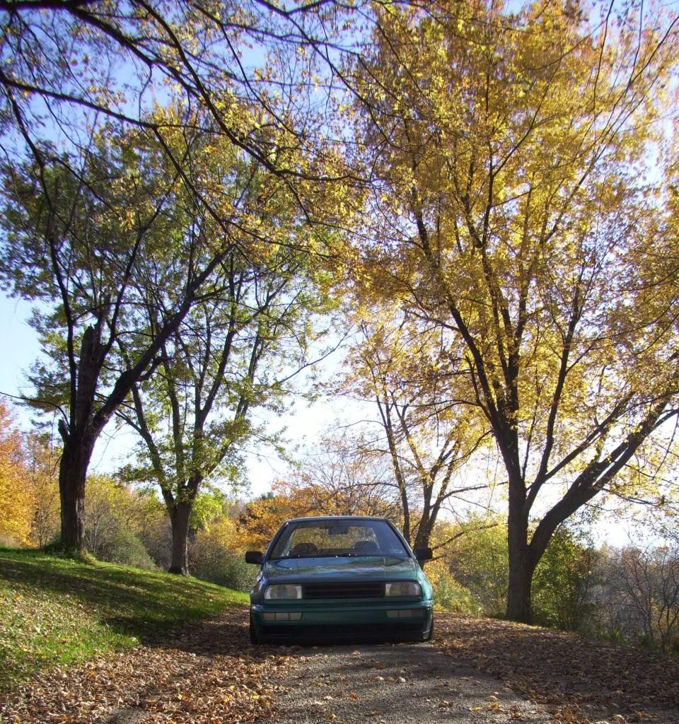
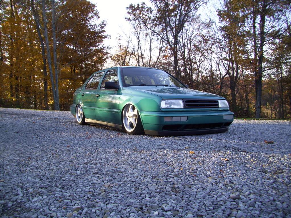
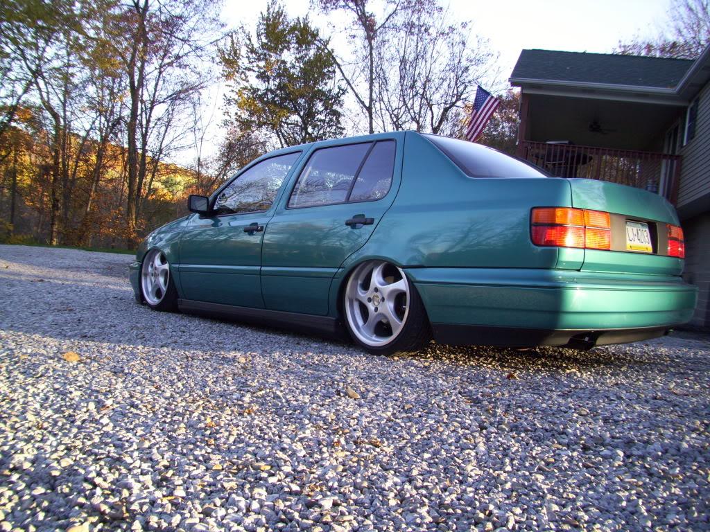
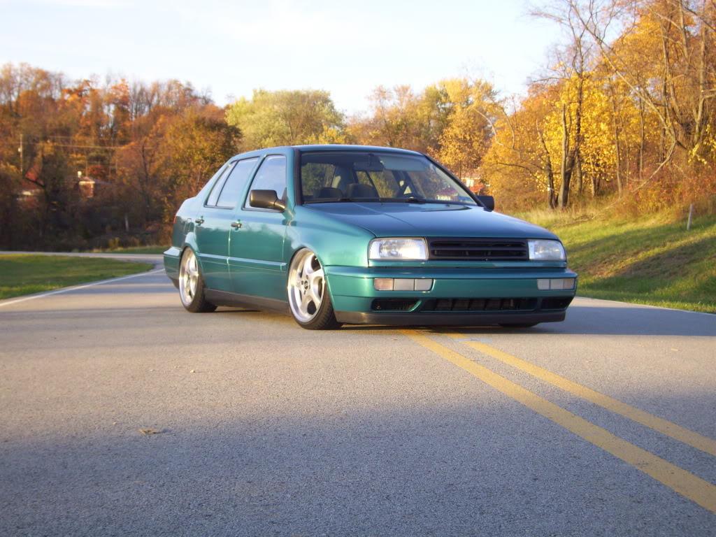
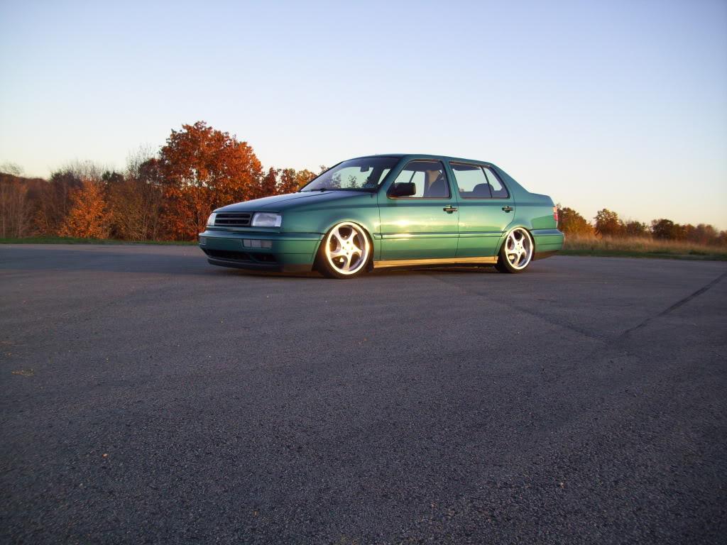
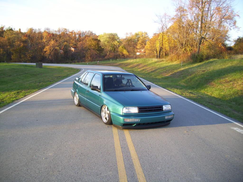
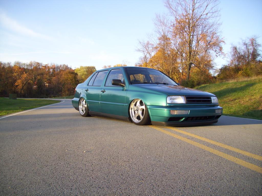
October 27, 2009
That pic is all the way up, about 1-1/2" off the ground. I'm not getting the full 2" of lift because my control arm bushings are binding up, they will be replaced with sphericals this winter and I should get full lift.
November 05, 2009
What's up Jason, welcome to the Vortex! I got a sweet Kia Spectra as a rental, the Jetta is back in its garage, hopefully I can start the bay this weekend. The Kia is a total turd!!
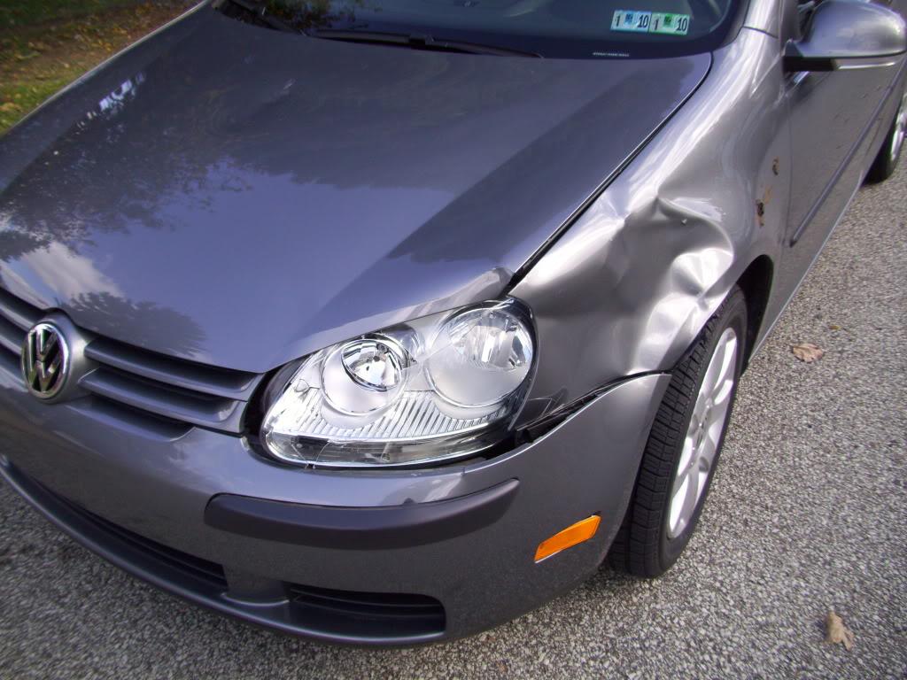
FYI I hit a deer in my mk5 daily, so I had to daily drive the Jetta for a little while.
October 27, 2010
I only have this one. I think they're hitting the fenders in this pic, they don't turn very far I can't turn at all when it's laid down.

January 06, 2011
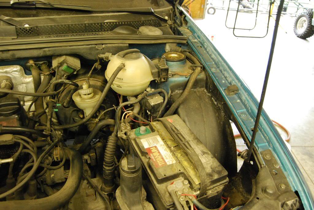
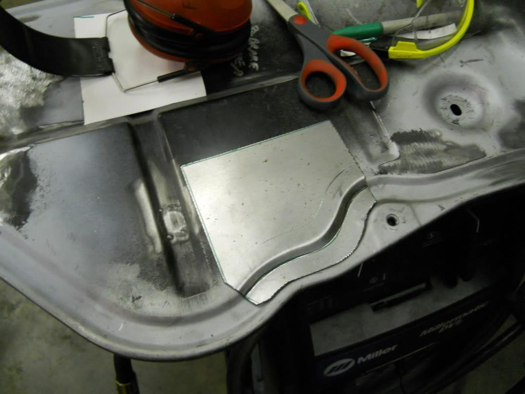
Still plugging away on the bay. I'll tease this, some firewall work I was doing last night
May 31, 2011
I enjoy reading the replies I'm really pushing hard to get it done for H2O '11 but it's going to be difficult. I still have a lot of work left, and a lot of things to pay for!
here are some updates/teasers:
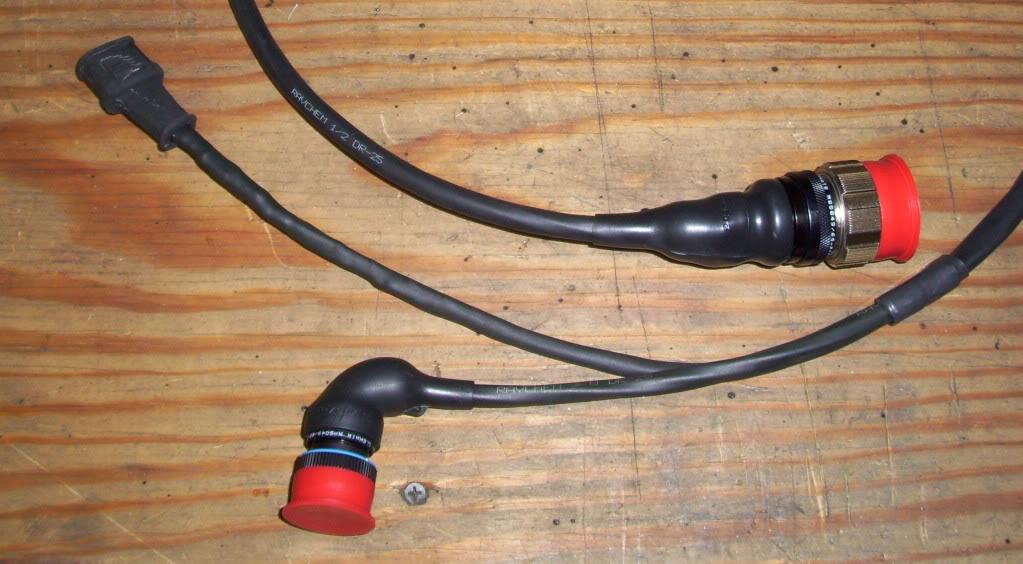
The wiring has all been redone, here is the fan harness:
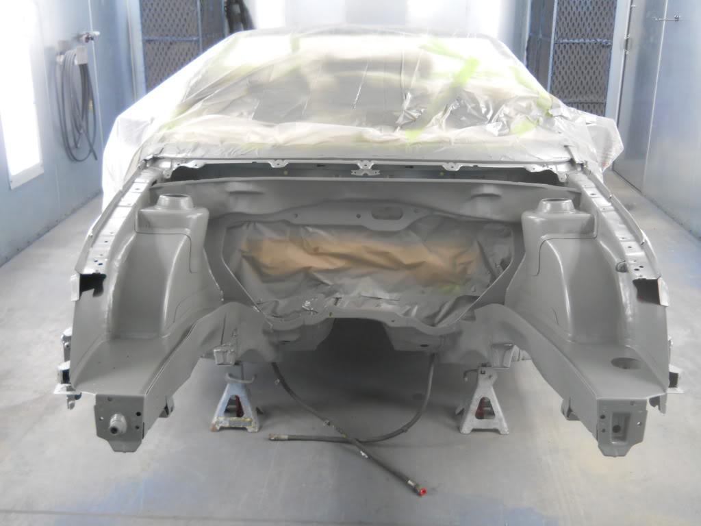
The metal work is basically done in the bay, it's time for bondo and finish work.
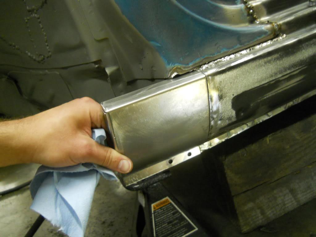
extending the rockers
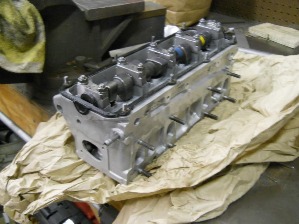
head is back from Scientific Rabbit. Ported and polished and rebuilt, stock valves but plenty of other work.
July 07, 2011
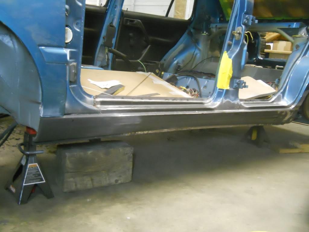
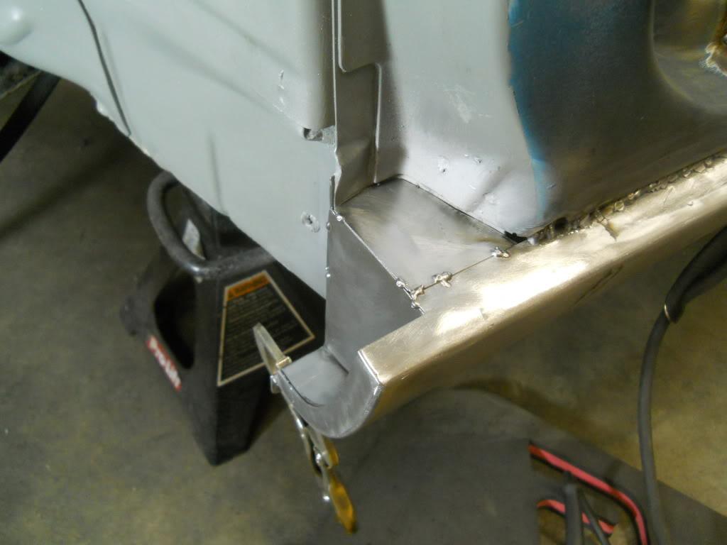
I dont' have finished rocker pics yet, I work slow! They're pretty close, I'm cleaning up the pinchwelds now and that's about the last thing left.
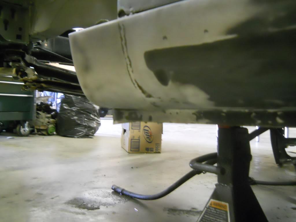
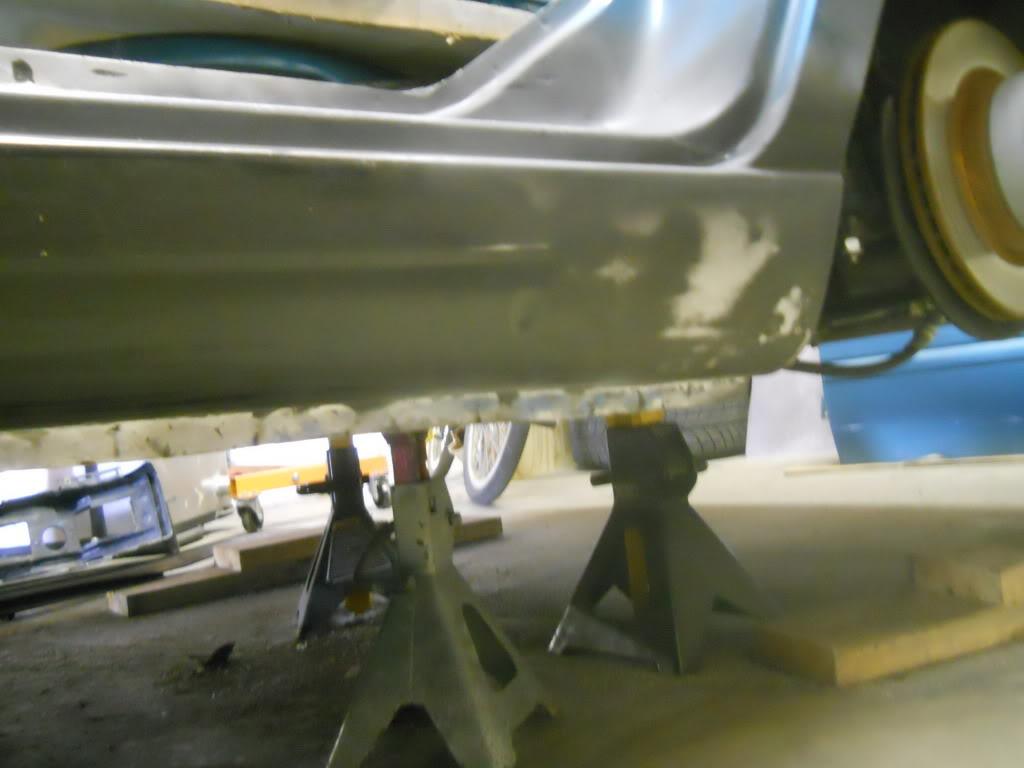
November 11, 2011
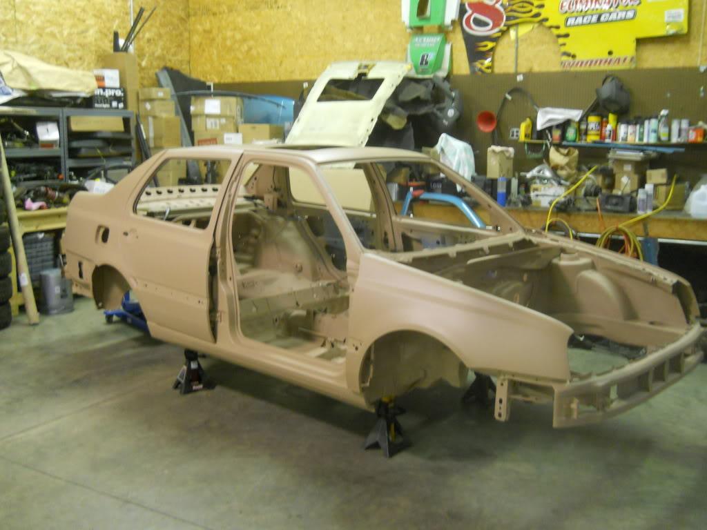
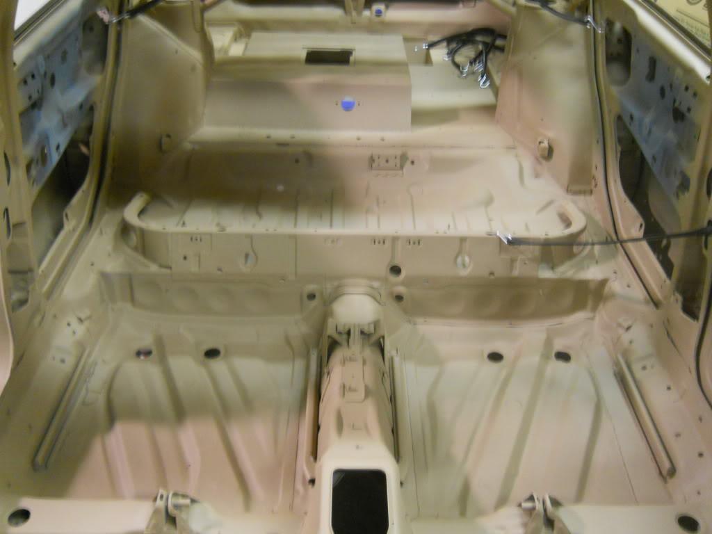
I got the shell back from media blast about a month ago. I have to repair some rust damage in the floor and add more reinforcements to the rockers, then I want to plan out my fuel lines so I can weld in mounts before I paint the bottom. Then bodywork and paint!
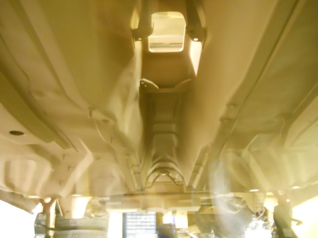
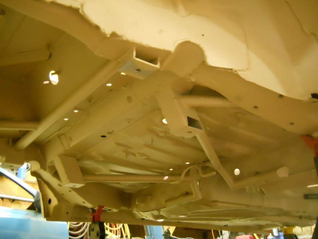
June 21, 2012
2013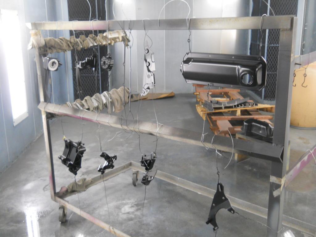
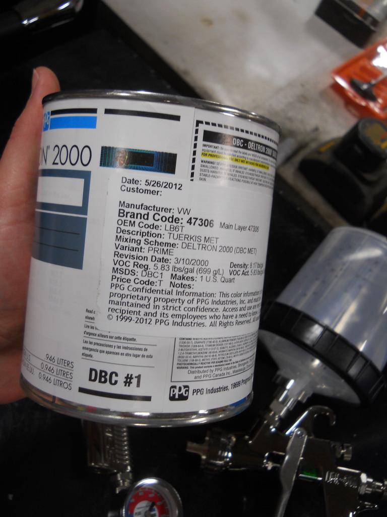
July 09, 2012
What year is your next H2O? It might have to wait until 2013 at the rate I'm moving! At least I'm starting to spray some color now.
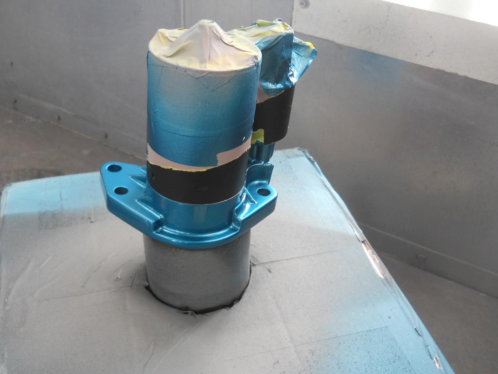
Nice build! Great photos and detail ????
Posted by Diggymart on 4/23/19 @ 12:52:48 PM