You must be logged in to rate content!
14 minute(s) of a 341 minute read
8-24-2009
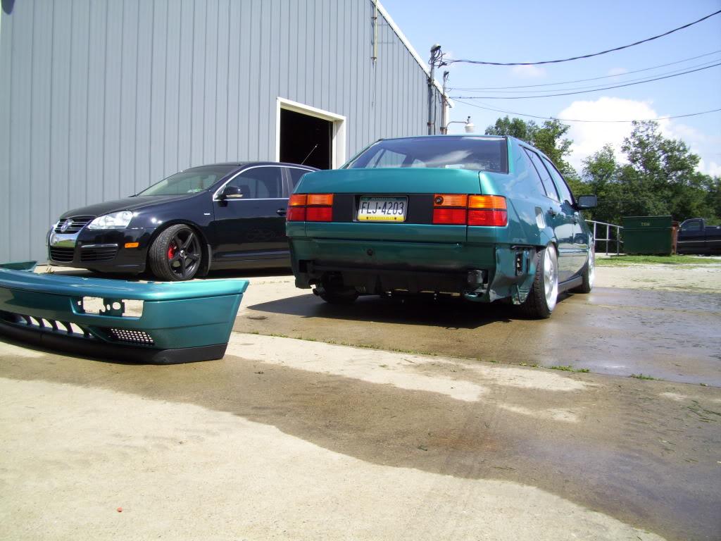
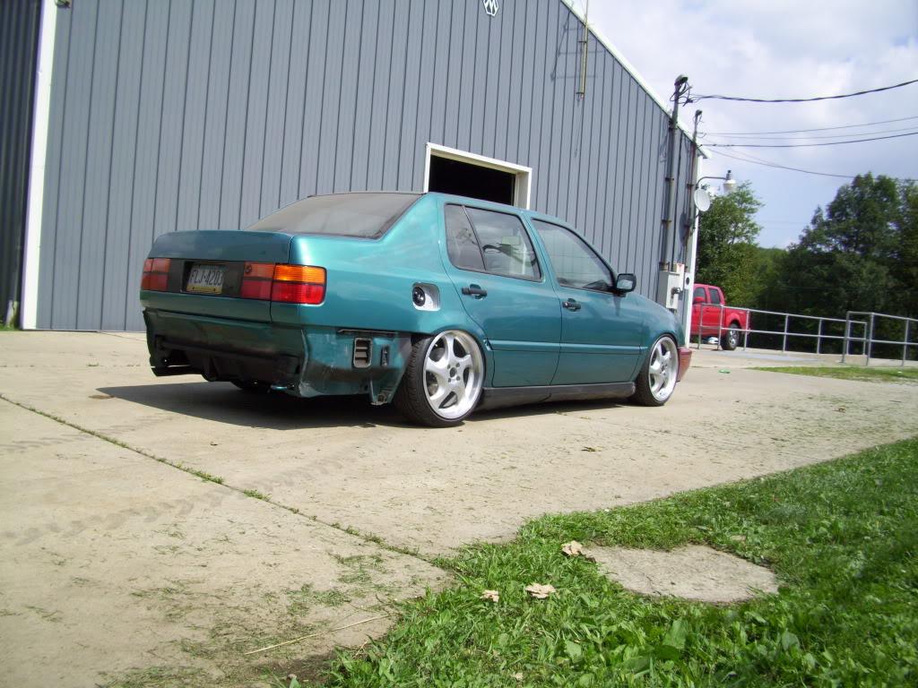
I took the day off work to get some work done on the car. I got everything all buttoned up and drove it outside!! It ran under its own power; started right up and everything worked! This is on 4 stock front struts, all blown out, and bumpstops stacked up to get it off the ground enough to roll. I took this opportunity to wash off the 8 months of garage dust and grime that had accumulated, it was really dirty! I was super excited to see the thing roll under its own power. It hadn't left the same corner of the garage since January!
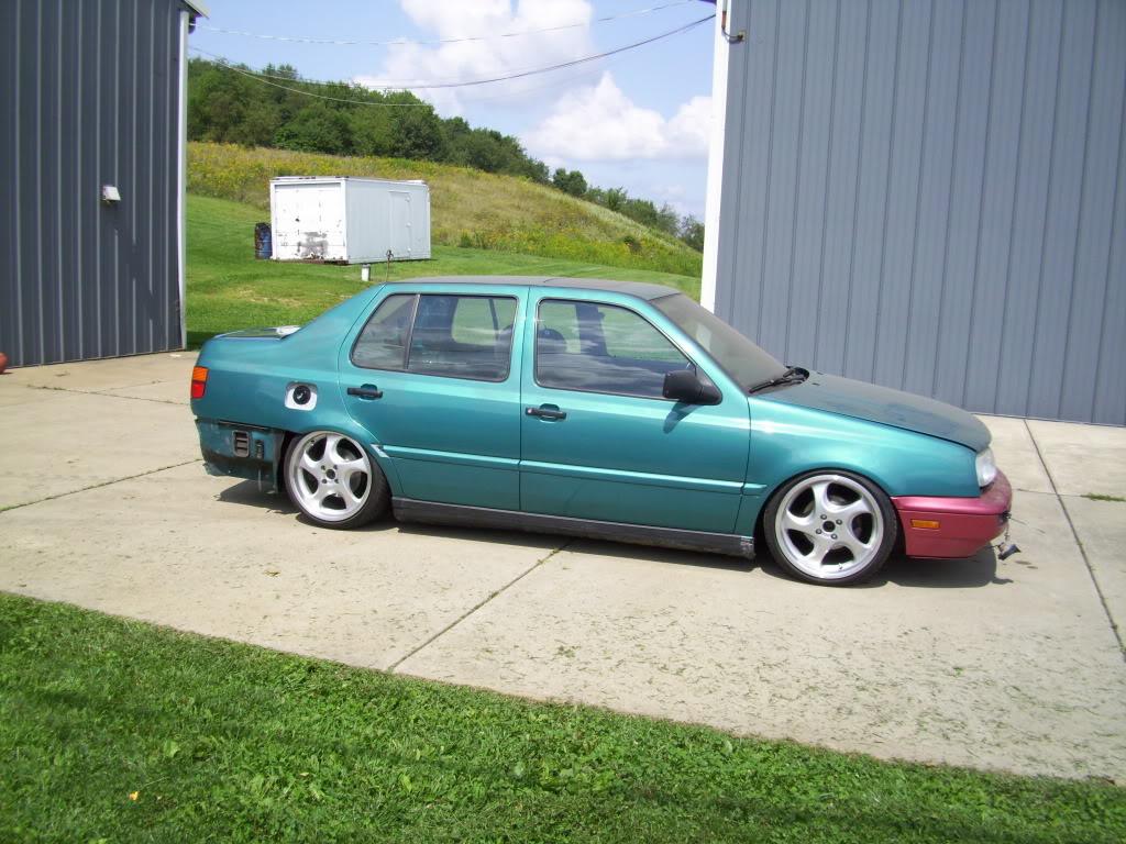
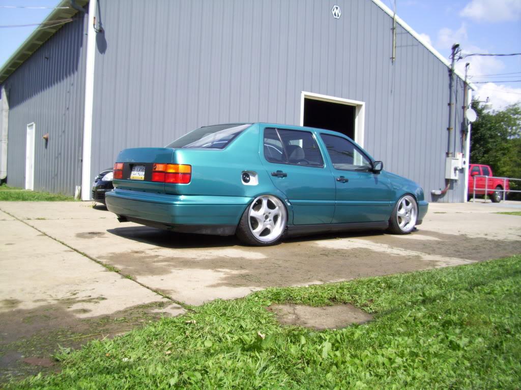
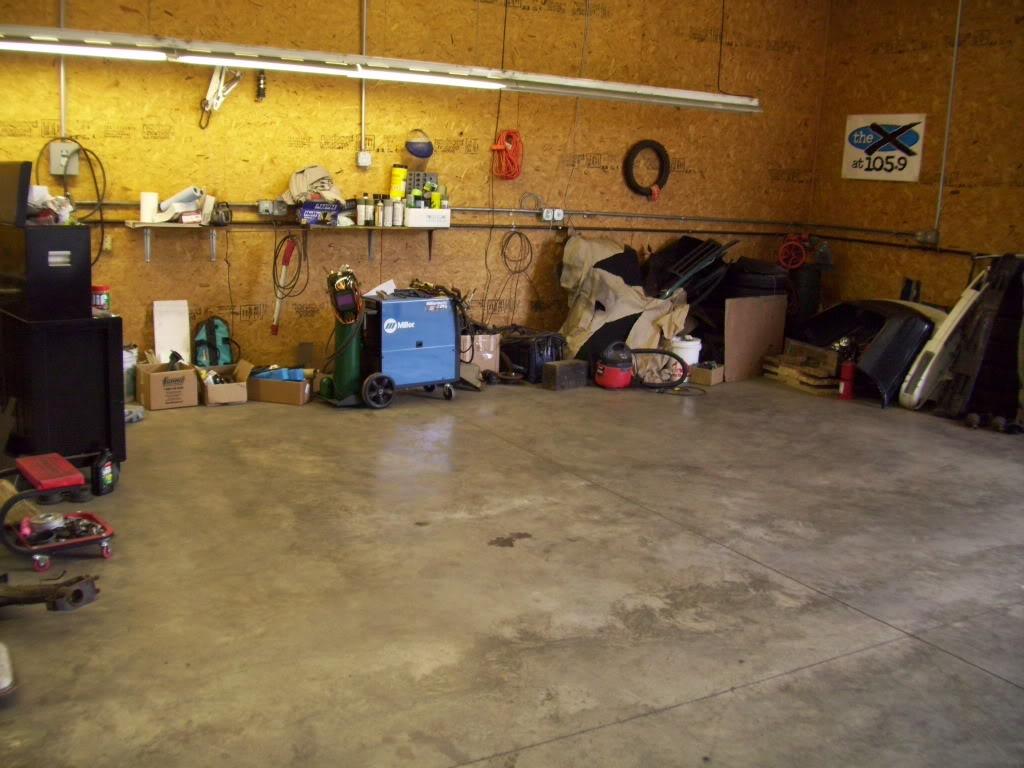
Cleaned up my mess while the car was basking in the sun
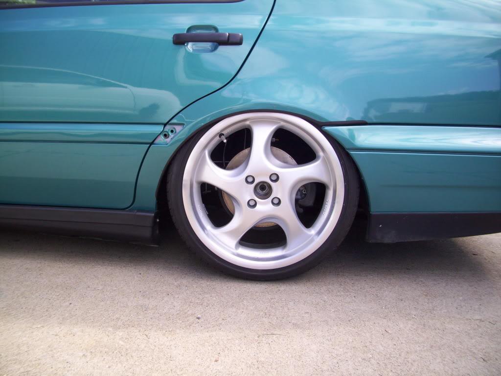
All sorts of camber to get it to roll
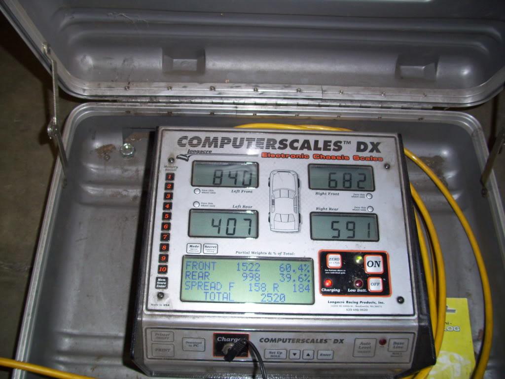
I got the car up on scales so I had an idea of what springs I wanted to order. This is without hydraulic pumps, 5gal of gas, no back seats, partial interior. That stuff all weighs about 150lb maybe? mostly over the rear wheels too. I haven't scaled it since the car was done.
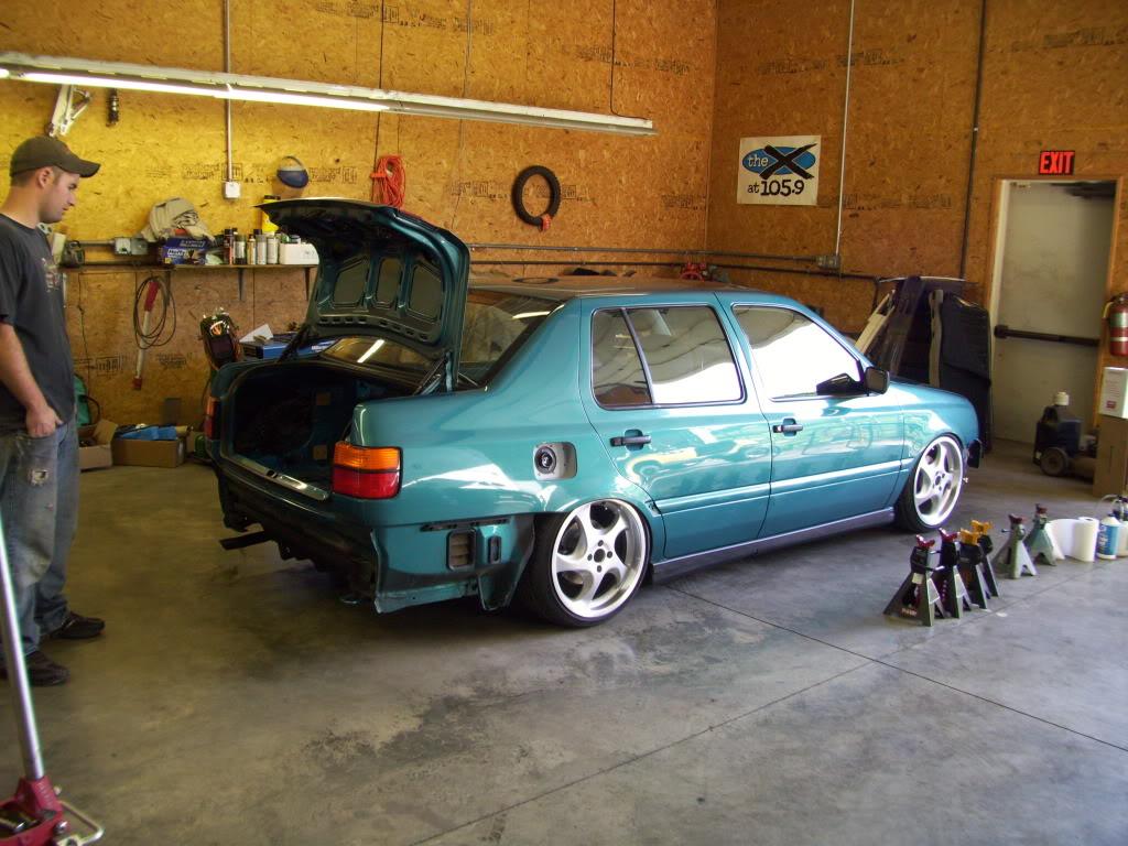
Woody (good buddy and TIG welder) looks on; the beast is back in its cage for the evening.
That's all the updates for tonight, I'm super tired and need to get to sleep. I'm away most of the weekend, but might get some updates in Saturday or Sunday evening. I will explain the hydraulic stuff I promise!
August 27, 2009
Less than one month to go!!!
Time to make the final decision about how this would be plumbed up.
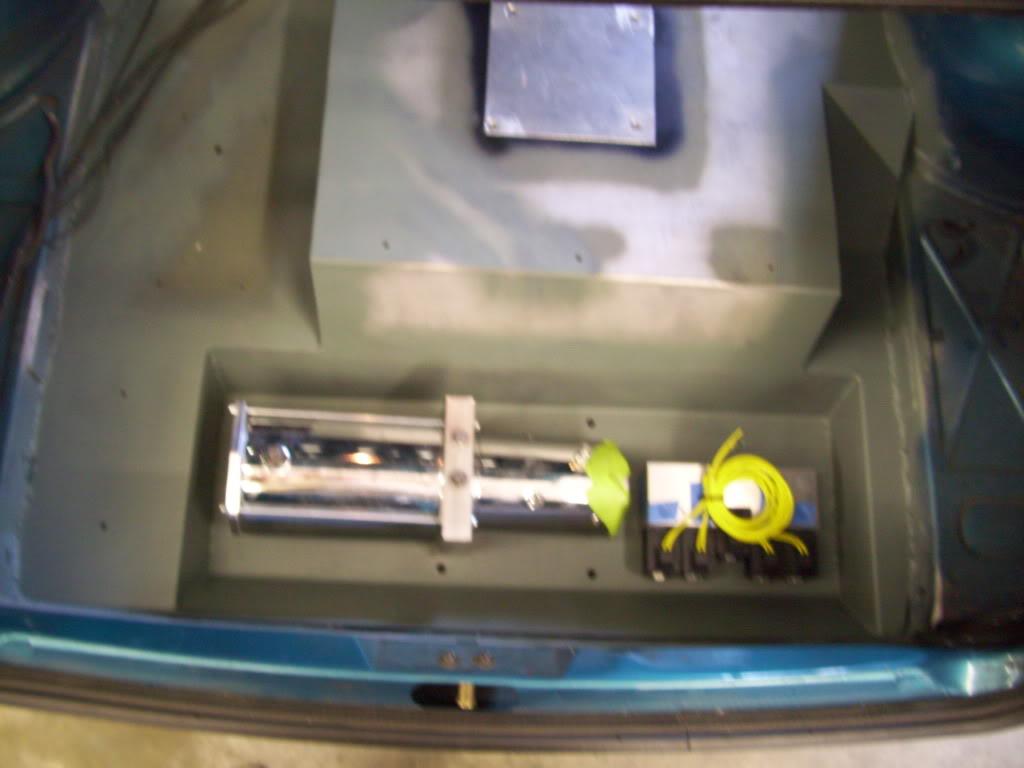
The pump is a standard lowrider pump, I bought it from http://www.hydroholics.net. I dealt almost exclusively with Derek, and he was very patient and helpful since my application was very different from the usual hydraulic setup. For anyone that's seen this before, it's a #9 Rockford gear, aluminum manifold (3/8" ports) and chrome motor. The manifold has Delta dumps.
The manifold is also from Hydroholics. It's a 5-dump manifold. "Dump" is lowrider lingo for a valve. This manifold allows individual control of each corner of the car, provided that you have enough switches wired in. I only plan to run two switches - front and rear. But with the 5-dump manifold, if I'm driving at an intermediate height, fluid will not transfer between corners while turning or braking or accelerating. I decided this was the best setup for what I was doing, although even at this point I wasn't sure if the pump would be strong enough for my custom pistons!
I had a few options for the layout of the pump and manifold - the two major components. I tried this first:
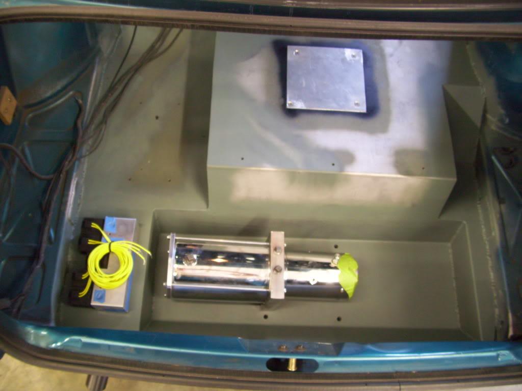
I didn't like that setup. Then I tried this, and decided this is where I wanted everything. The fluid lines for each corner would come out the bottom of the manifold on the bottom of the floor, and would be pretty well protected by the fuel cell cradle.
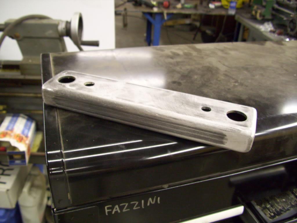
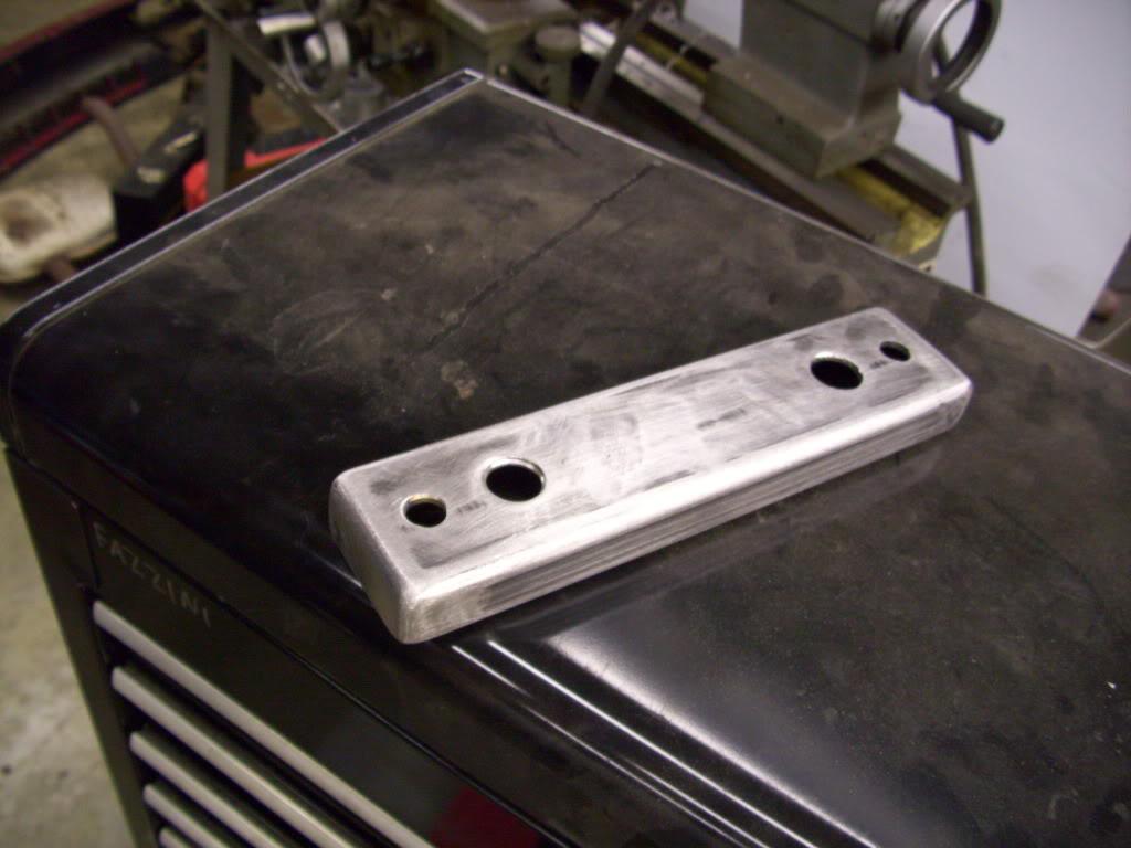
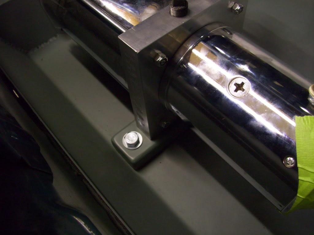
I made this bracket from 1/8" steel to mount the pump to the threaded inserts that were welded in the floor a few weeks prior. The pump bolts to this bracket, then the pump/bracket bolt down to the floor.
Top view:
Bottom view:
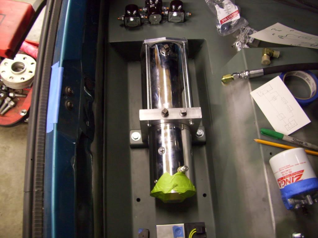
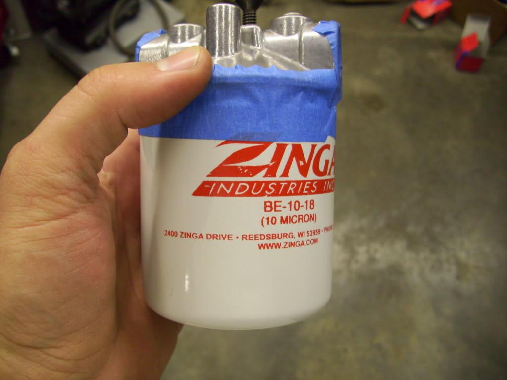
I decided to run a filter on the return line, just to filter out any crap that gets into the lines or metal particles that wear off of the pistons.
I made this aluminum plate to mount the manifold to, then I could bolt the plate down to the floor.
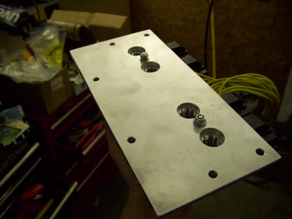
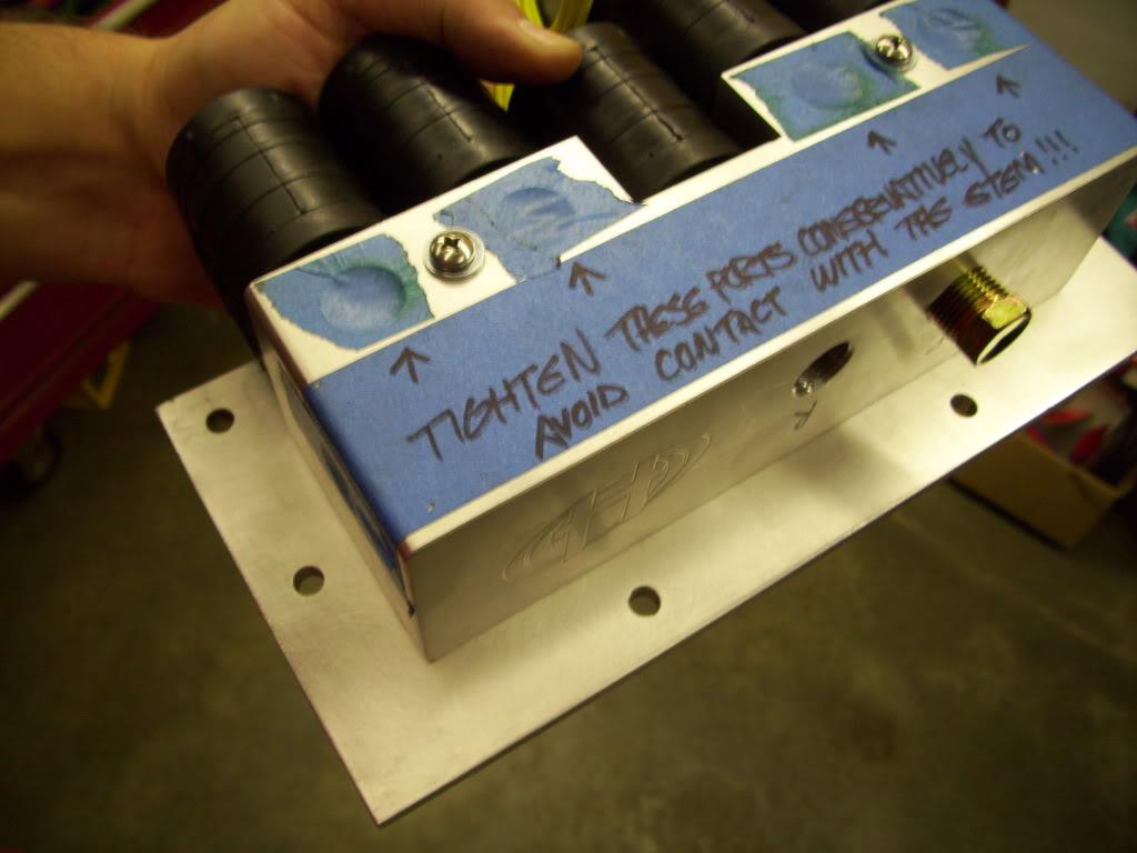
I cut a hole through the floor to mount the manifold plate
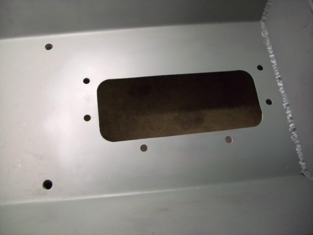
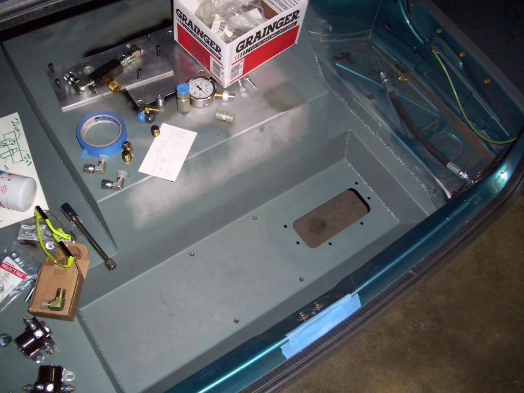
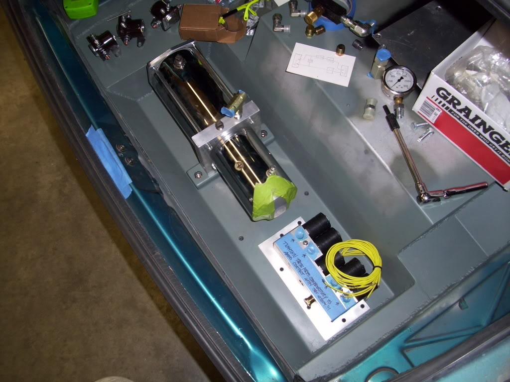
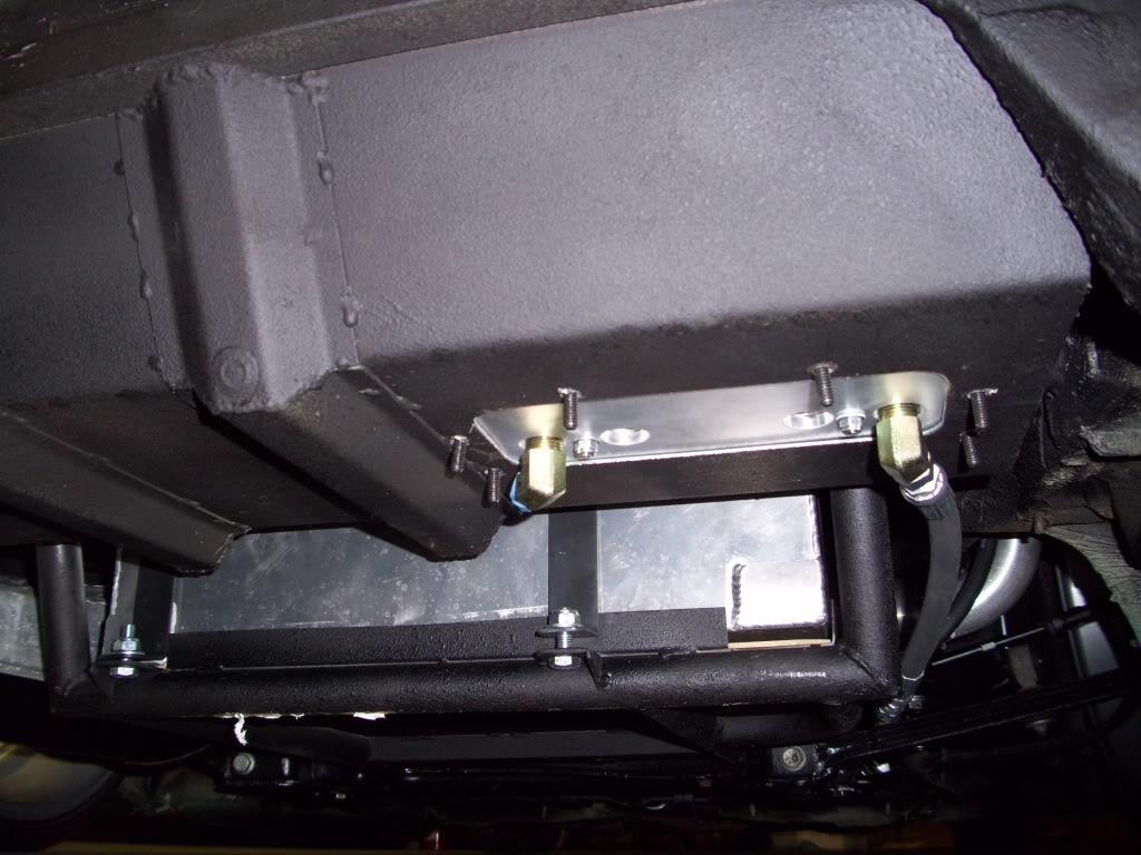
Here is where the hoses will come out the bottom of the car. Each of the 4 fittings will send fluid to each corner.
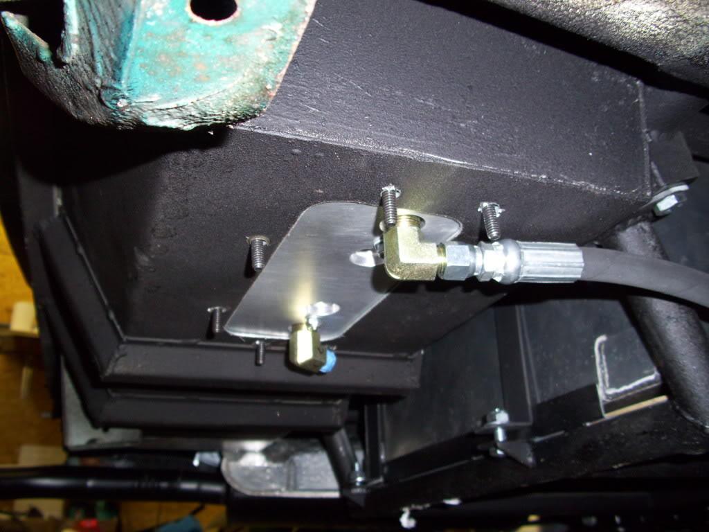
Here's a view from the rear of the car, you can see the hoses are a few inches above the fuel cell cradle so it's pretty well protected.
August 30, 2009
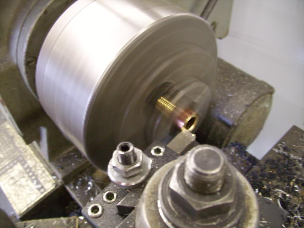
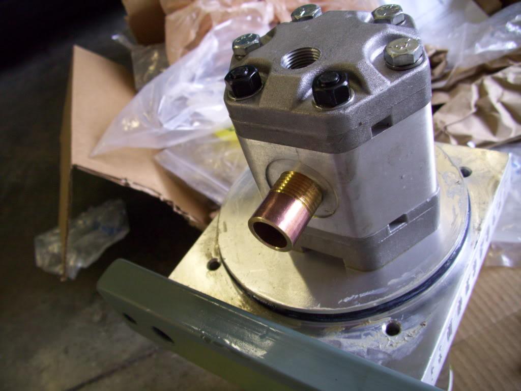
I machined a new pickup tube for the pumphead. Because I'm mounting the hydraulic pump at a different angle than the standard Hydroholics method, I had to make a new pickup tube to pull oil from the bottom of the tank. With these pumps the pumphead itself is inside the fluid reservior, then the motor is on the opposite side of the "block" (large plate between the reservior and motor.
Turned down a brass nipple
Here is the pumphead mounted to the block with the fluid reservior removed. You can't see the motor, it's on the other side.
I still had to drill the fitting port holes in the side of my pistons. This is the fluid inlet for the hydraulic pistons which will mount on each strut. I have 4 plus two spares for a total of 6 pistons. The fitting is a -4 SAE O-Ring Boss, which seals using an o-ring. They're reuseable, consistent, not subject to thermal cycling, hold more pressure than I will ever need. Much better than NPT in the high pressure hydraulic world!!
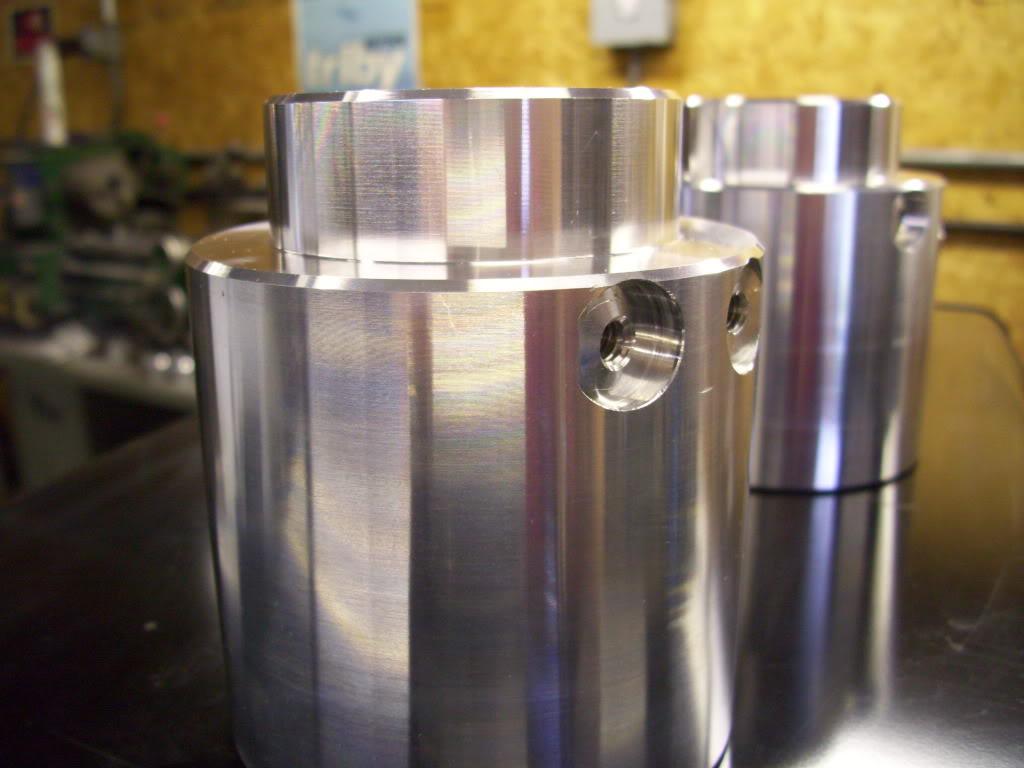
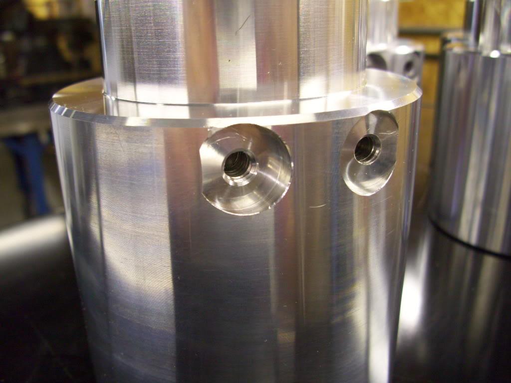
I borrowed some time on a milling machine and did this part myself. I also had to drill two holes at the back of the pistons for anti-rotation pins which will keep the piston from rotating and prevent the fitting from rotating into the tire. Again, more on the hydraulics later.
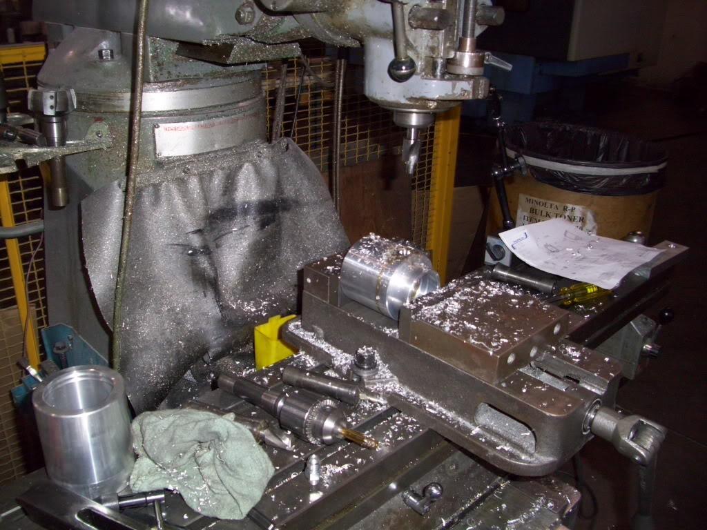
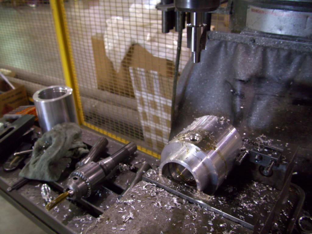
All finished!
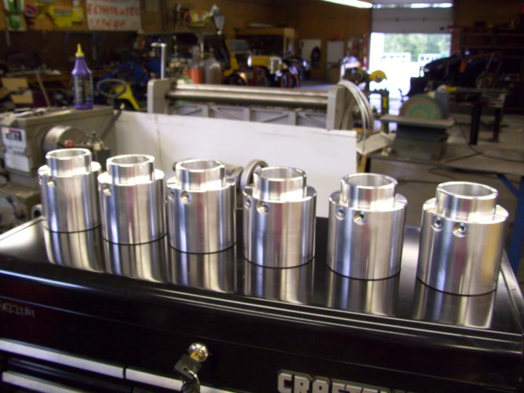
Here is the fitting hole:
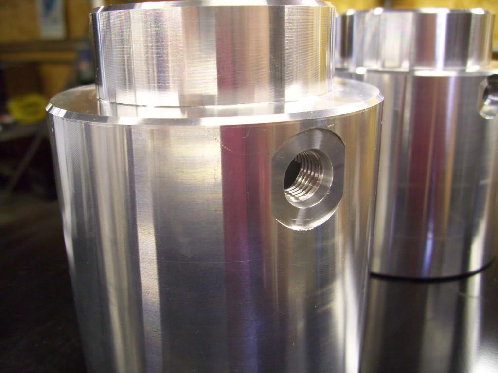
Here is the fitting installed:
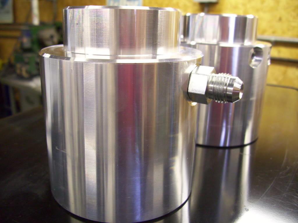
Here is the inside of the piston:
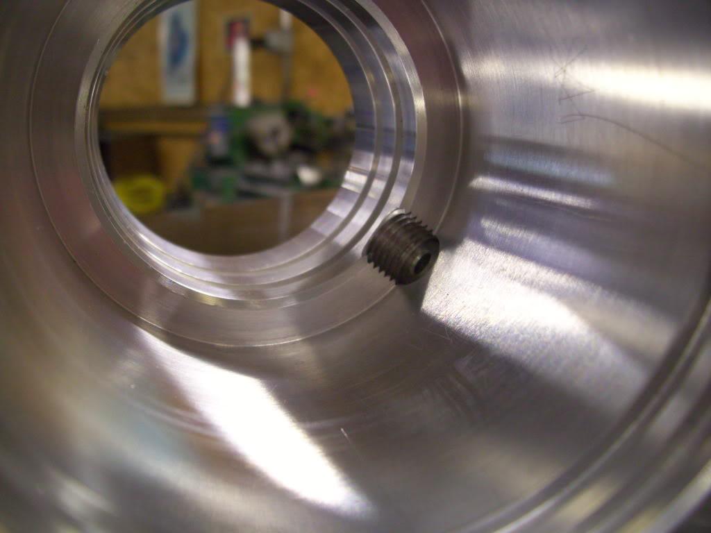
Here are the two tapped holes I made for mounting the anti-rotation features. Again I will fully explain this later, but two pins will be screwed into here which will ride on a pin to prevent the piston from rotating on the strut.
Because the hydraulic motor grounds through the housing, you need to ground the bracket that mounts it to the chassis. There is only one hookup on the motor: 12v power. I painted the bracket and removed the paint on the bracket and on the trunk floor for better contact:
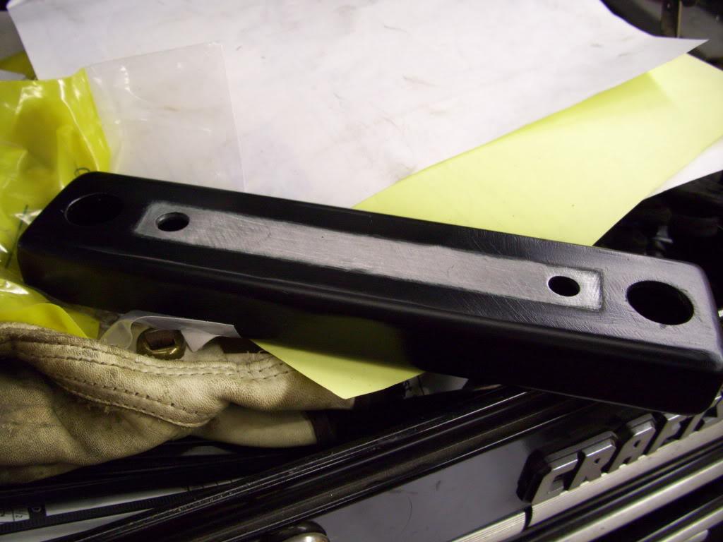
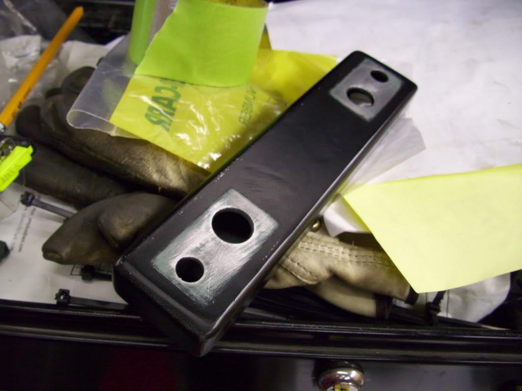
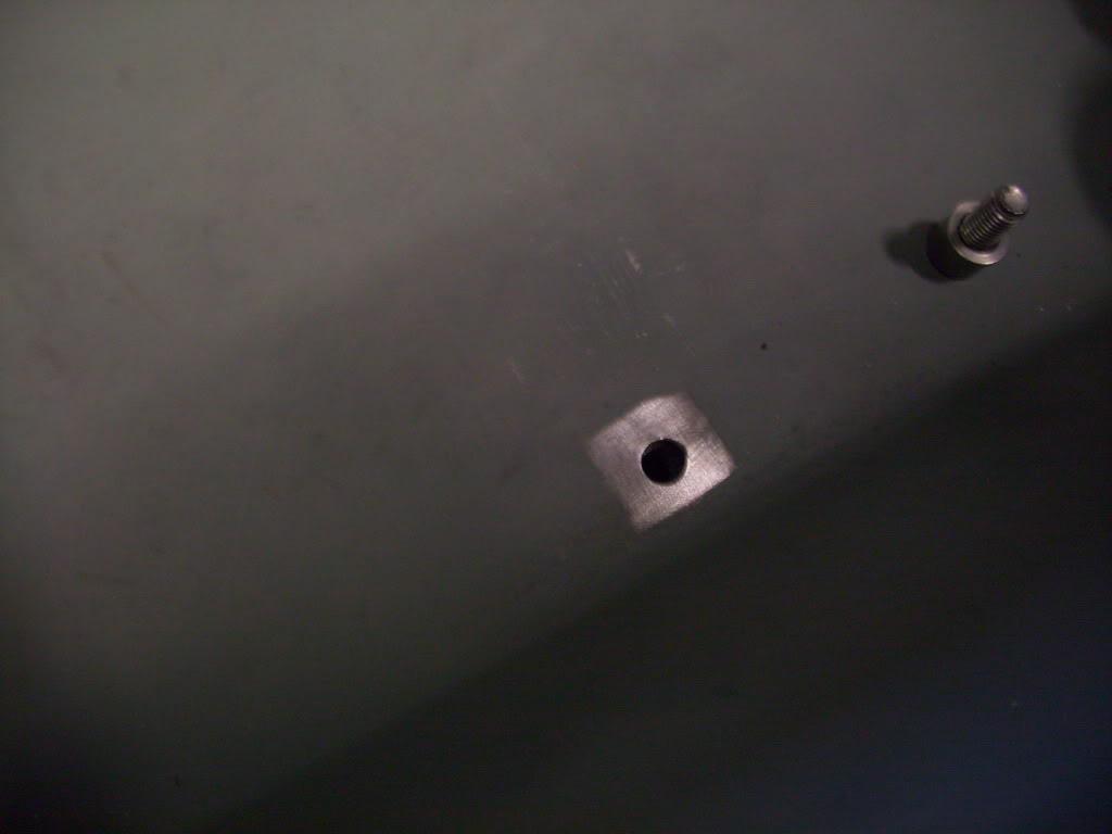
Then I started plumbing up the setup. I used all zinc plated steel hydraulic fittings, either 3/8" NPT or -6 JIC flare. I used yellow Teflon "gas tape" to seal the NPT threads.
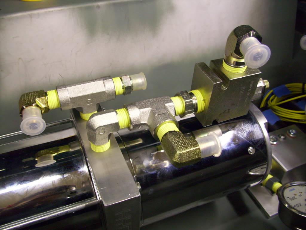
This thing here is a pressure relieving regulator. When pressure exceeds the preset value, it bleeds fluid back into the reservior. This is helpful because I can just hold the "up" switch down until the car tops out, then the valve will open and excess fluid will just dump back into the tank until I let off the switch. It's adjustable from 500psi all the way to 5000psi. I need about 400psi to lift the car, and have it set to 1000psi just for uneven surfaces and so it doesn't bleed off when it's lifting and the pressure spikes slightly
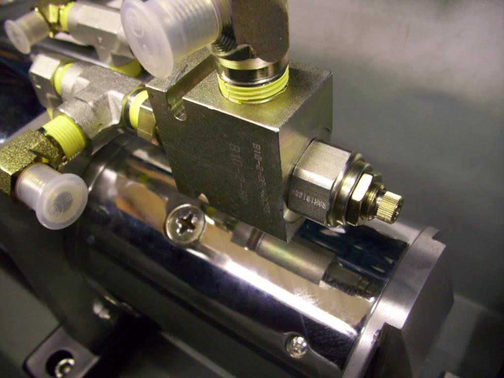
Here is the manifold:
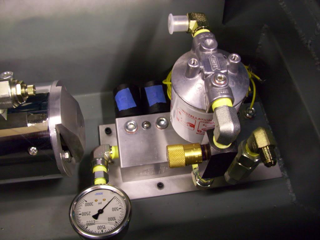
At the right side of the picture, that's the fluid inlet. It goes through a check valve to prevent fluid back-flow into the pump, then into the manifold. Coming out of the front center of the manifold is the return path. When I lower the car, fluid flows through the flow-control valve (adjustable for drop speed) then through the filter, then back into the reservior. The 3000psi gauge on the left is to for setting the pressure relief valve, and to aid in troubleshooting if I ever have any problems.
August 31, 2009
I got the fuel filler neck guard all cleaned and painted up
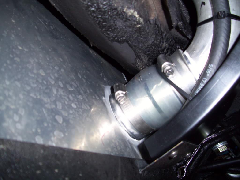
Here is the coupler for the fillerneck into the tank, I haven't pictured this before I don't think but it was done a few days prior.
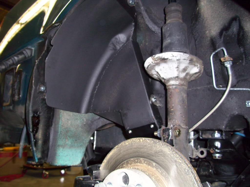
I found some spring seats from an old Ebay coilover kit that I can use for the rear upper spring seats. This saved some machining time!
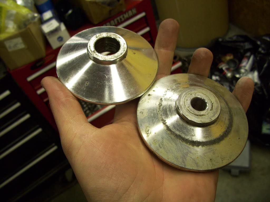
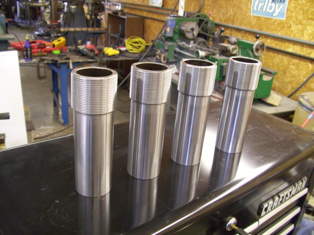
My friend Woody machined these for me. He's a damn good CNC lathe operator, and made a few of the parts for the suspension that I wasn't capable of making. He whipped these up - the lower half of the rear struts. This is the last machined part for the suspension that I won't be making!
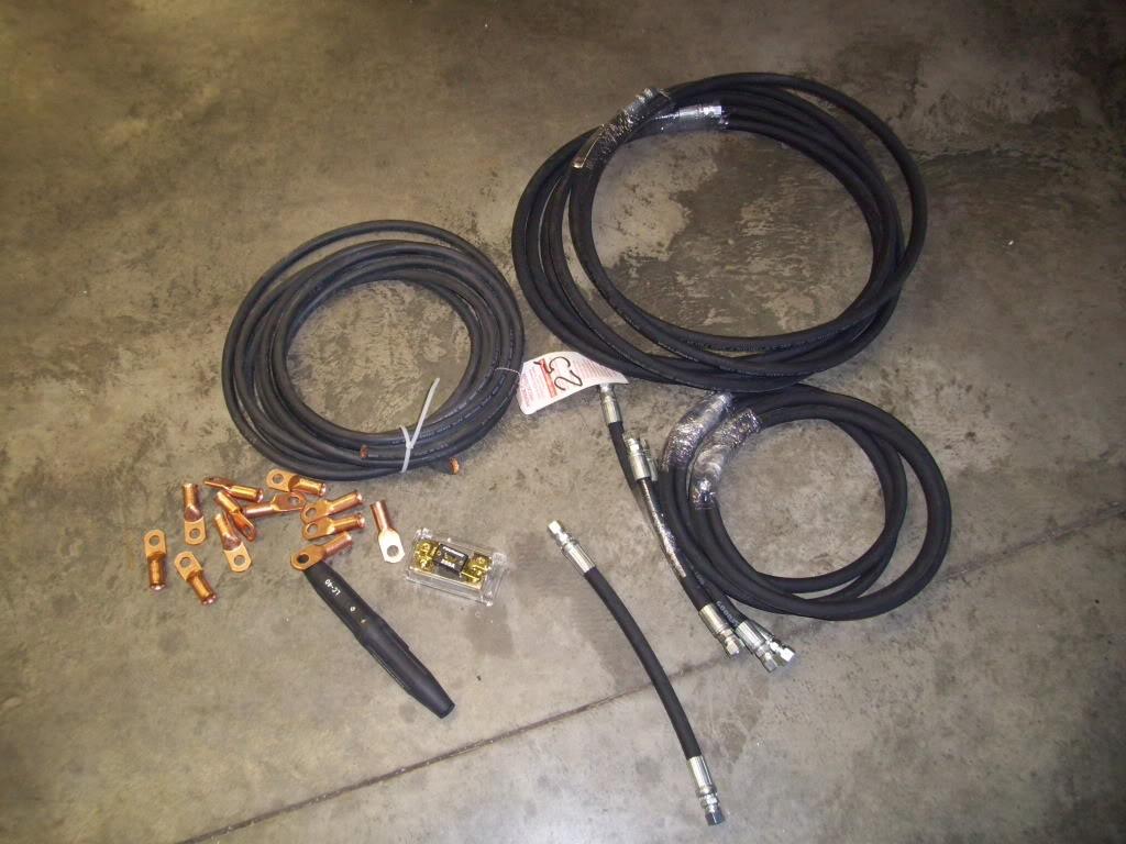
I had a chance to get all the hydraulic hoses made and buy the power wire and fuses and connectors for the whole hydraulic setup. The hoses are Goodyear GR16SC. 5,000psi working pressure, 20,000psi burst pressure. -6 JIC straight swivel ends. The power wire is 2/0 copper welding cable, 200A fuse.
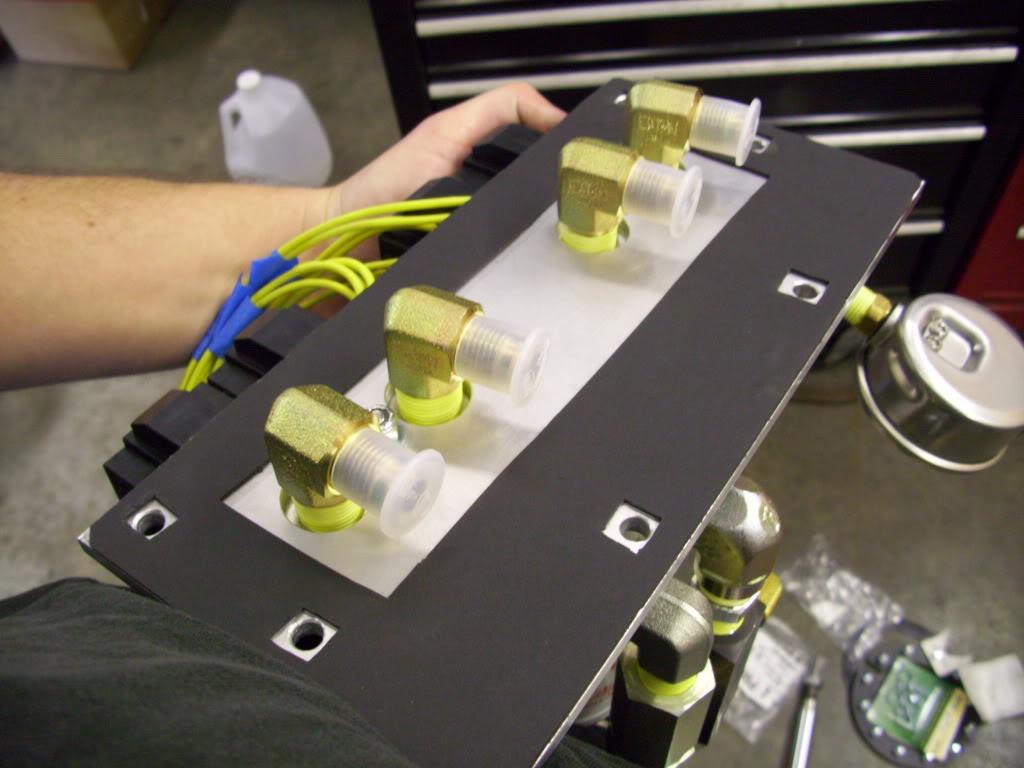
I pulled off the manifold plate and made a rubber gasket for it to seal it from the elements.
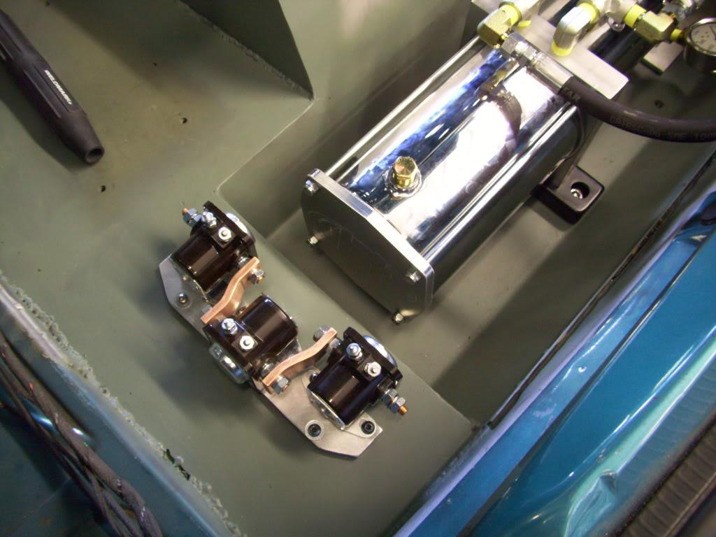
In order to switch the hydraulic motor on, you need to use a relay. Because the current is so high and the relays most lowrider guys use are undersized, they typically run several in series in case they weld closed. When you run one relay (called 'Solenoids') and it welds shut, the motor will stay running. If you run 3, you have to weld all 3 before you get a runaway motor, which is highly unlikely and reduces your chance of a problem.
I made these copper bars to connect them
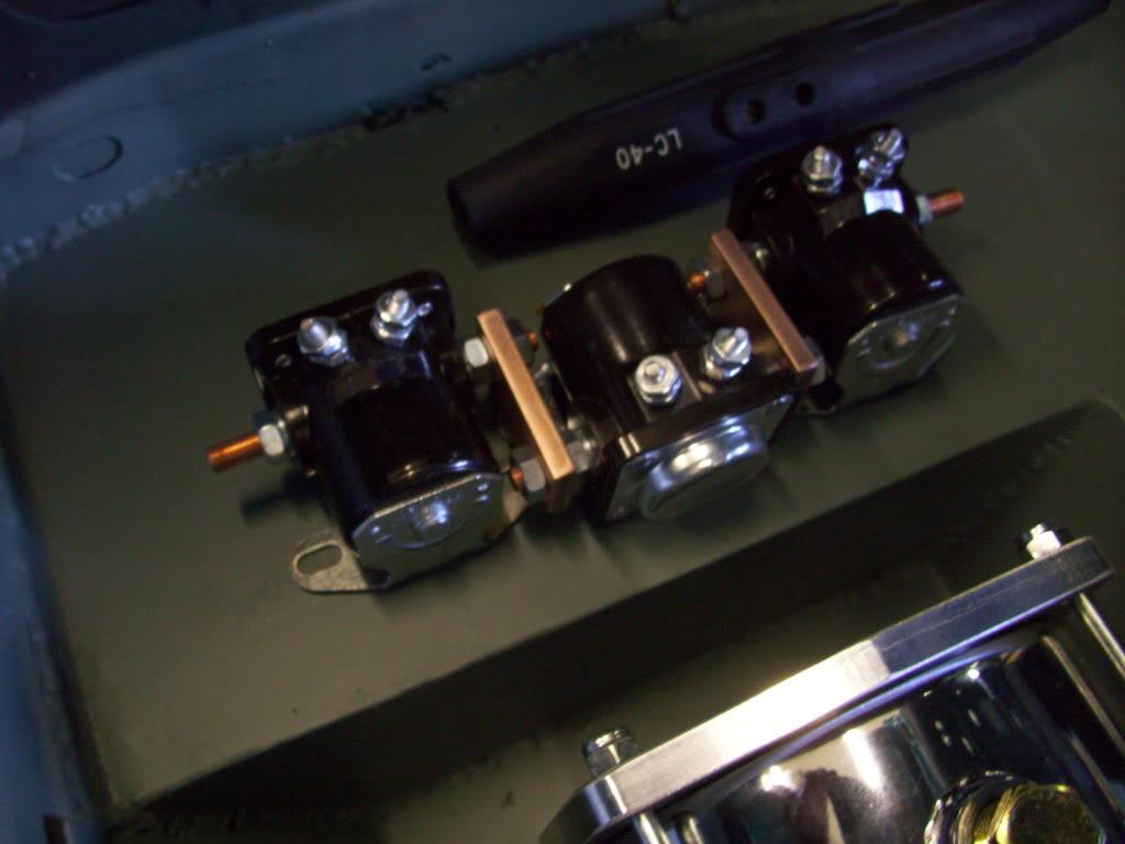
After looking, they were pretty close to the housings:
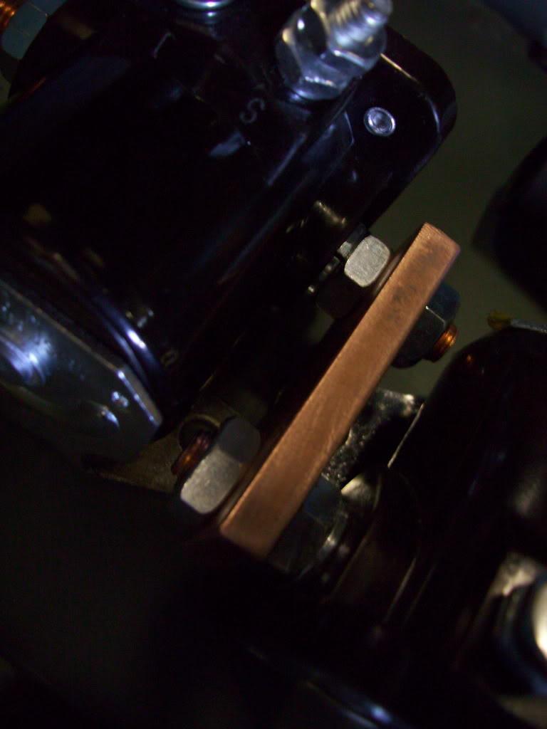
That's no good.
I remade the copper bars and added a little bend to space them apart, to eliminate the chance of arcing across to the housing of the next solenoid.
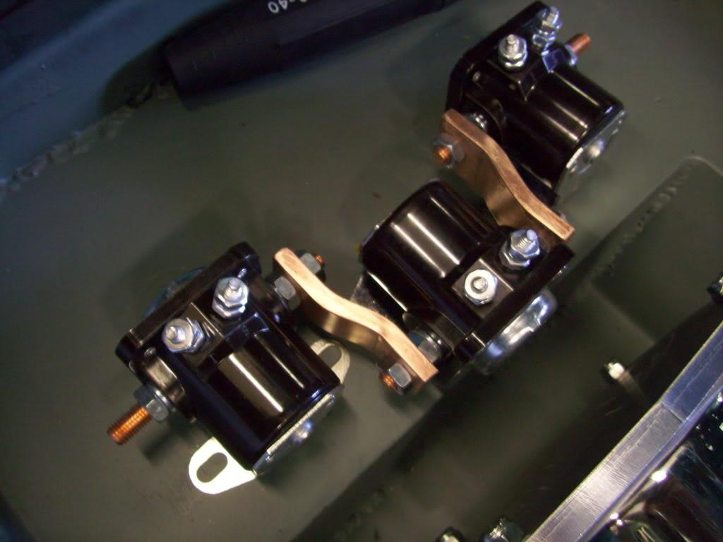
Then I made this aluminum bracket to mount them all onto.
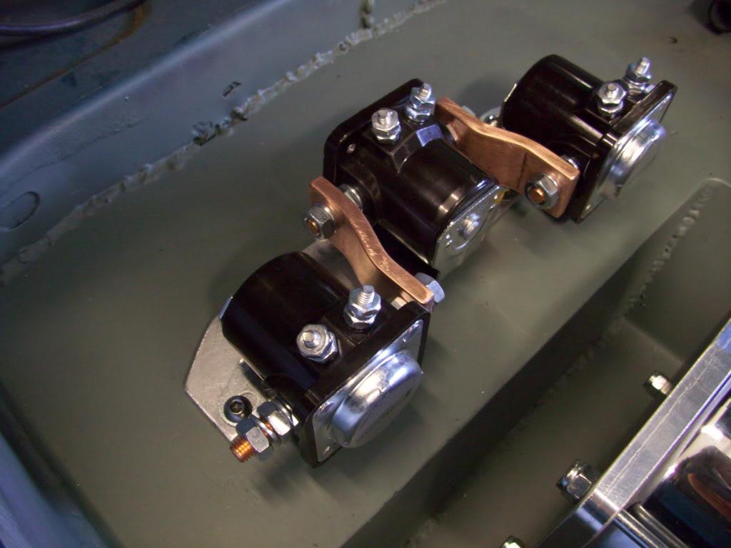
I got the hydraulic hose connections in the trunk all made. One hose from the pressure relief valve into the manifold, one return hose from the filter back to the tank, and one return valve from the relief valve back to the tank.
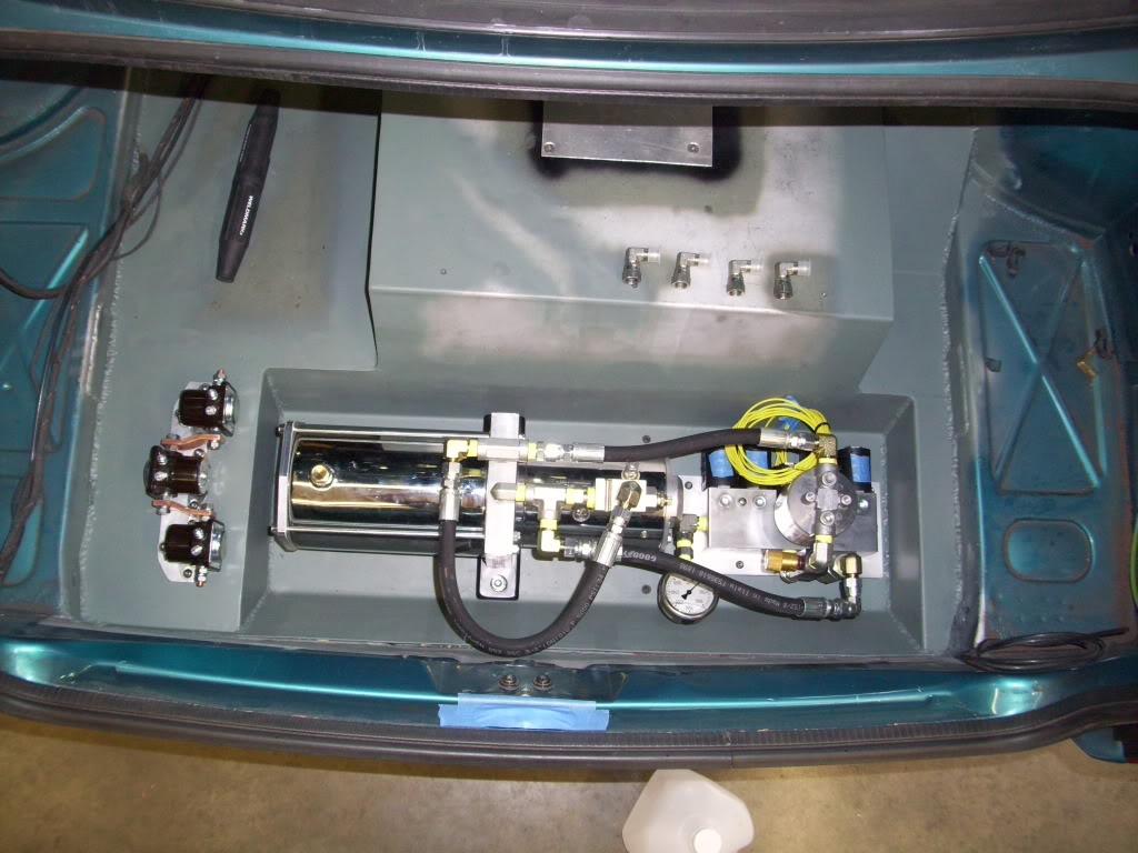
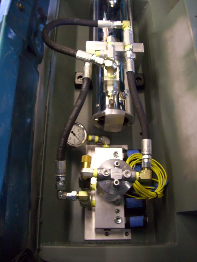
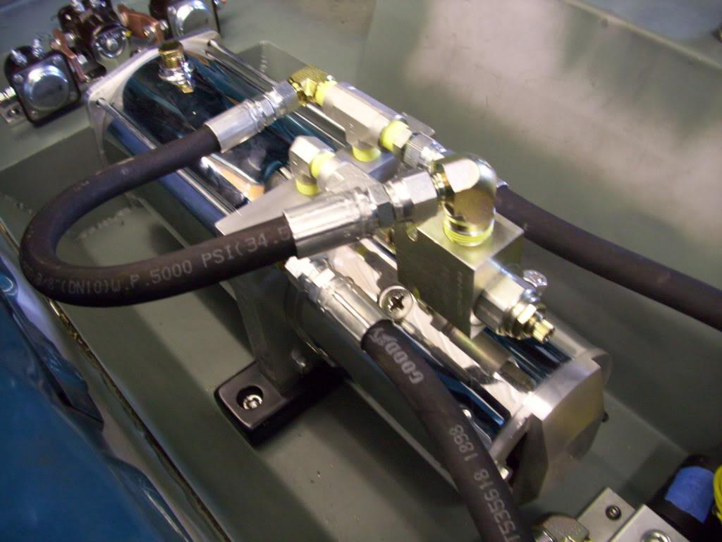
That concludes August 2009. More updates soon!

Nice build! Great photos and detail ????
Posted by Diggymart on 4/23/19 @ 12:52:48 PM