You must be logged in to rate content!
75 minute(s) of a 280 minute read
1-8-2011
An End-of-build Retrospective on my Rx7 Evo GT
Compliments of gmonsen @ www.rx7club.com
1-8-2011
I am finally making it out to Sevenstock this year and am putting together an overview of my car that I'm probably going to put on a poster and have available as printed handouts. So, I've decided to summarize and share the things I've done to my car over the past 4 years along with the few things remaining in one thread and in an organized way. I am going to talk about why I did the things I did and something about the choices I made. These are my favorite things. Any and all comments and questions welcome. I've divided it up by exterior, interior, chassis and suspension, and motor.
The car is not quite done and I'll post the final changes as updates through till probably the end of February or so, depending on whether I decide to paint it before Deals Gap. Mainly left is some experimentation with the motor and dyno comparisons, a few small cosmetic bits and pieces, like the new emblems, some suspension tuning, and then some performance figures and weight by corner.
Modifying
There are all kinds of builds and ways of modifying cars based on budget and objectives. I had a very clear idea of what I wanted based on owning another FD for years and a very clear budget. I didn't make lists of parts, but thought for a long time about what I wanted to end up with and wrote down a lot about each aspect of the car and then about how those pieces all fit together. Then I figured out how I wanted to implement each thing, whether the choice was buying a part or making something or modifying something.
Grand Touring with a 20b-powered car
So, my car has a very stock looking interior and exterior, a naturally aspirated 350 whp 20b motor, and a moderately upgraded suspension. It looks stock despite a few external touches that are not even visible in many pictures at all. The interior looks stock, but every part is essentially custom redone leather, metal, and wool with the result being that its very comfortable and luxurious. Its fine on the track, but is the best on the highways and backroads. Imagine a very quiet interior with some quiet background tunes sitting on some serious leather cushions. Grand Touring.
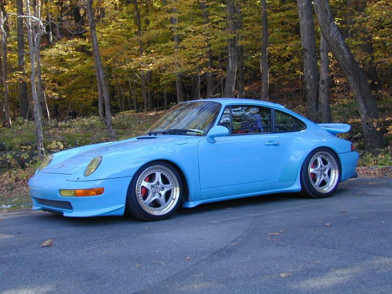
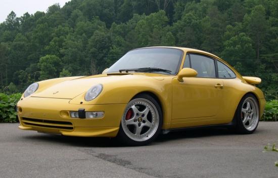
Evolution
I set out to build a natural evolution of the Rx7 like the evolution of the 911 over time. I wanted the car to evolve into something a bit more exotic, more powerful, more purely rotary, while being more comfortable and having an interior like the best sports cars made. I didnt want it to jump out at people, but instead be something that they honestly mistake for a factory made car that they just never heard of before. This car could have easily been created by Mazda from parts they had readily available and by simply changing the interior material specification, fit and finish.
Balance
The car is all about balance. Not too much horsepower, not too stiff spring rates, not too big wheels, not too many cosmetic changes, but an attempt to upgrade each major aspect of the original cars specification and performance to the same level or extent as all the others and where no one aspect of the car overwhelms any other or the chassis. The original car had remarkable balance and so should mine.
Budgeting
Its also about balance in terms of costs. No 20b conversion is an inexpensive undertaking and mine was no exception. So, in each separate area of the car I may not have done whatever the ultimate might have been. Had I done so, it would have doubled the cost and not really been a factory evolution at all, but obviously a very, very special one off show car. I wanted to build a car that Mazda could build today for the same time-value-adjusted-dollars as the cars cost when introduced.
Im not about giving advice, but cant help but emphasize something I just said. In every area of your car, there are aftermarket pieces that cost three or more times the average price for that piece. Take Ianetti seals at, what, $1500 whereas other very good seals are $600 or so. If you try to find and buy the best piece everywhere, your build is going to cost you a fortune. If you can make it a rule never to buy the most expensive pieces, but to try to buy at the top of the middle, you can control your ultimate costs much better. At the same time, this budget control helps ensure you dont end up with a build where one or two things are great, but there was clearly not enough money left over for some areas and they suffered.
I hope there are some things here that some of you haven't seen... ![]()
EXTERIOR
Ill start with the few exterior modifications Ive done. The exterior of the 3rd generation Rx7 is as near
perfect a design as possible, so I didnt want to change the lines in any way. All my efforts were simply to
see if I could enhance it a bit through small details.
New Emblem
I never have liked the emblems that came with the 3rd generation Rx7, though I have used the Efini emb-
lem for many years. They dont mean anything and there is no heritage or legacy symbol for Mazda or the
Rx7,
like there are for Jaguars or Ferraris or Porsches. Maybe thats why the Mazda emblems are all made out
of plastic?
The Rx7 is very much like the old Datsun/Nissan Z cars. Everybody knows what a Z is and everybody
knows what a 7 is and so Ive commissioned a new set of emblems that are the same size and shape as
the Efini emblems, but simply have the number 7 inside a rotor shape. These will replace the front hood
and rear hatch emblems and all other identification.
The emblems are going to be made of three layers of metal welded with parts painted or polished and will
be about the same size as the stock Efini emblem. Ill update the pictures here with the completed emblems
when they are done.
_______________________
Here is the final design for the emblem:

Here are the initial drawings I did for it:

This shows the 3 pieces that will make up the emblem:

And here is a version of the emblem out of polished metals:

_______________________________________
Knight Sports Sleepy Eye Headlights
Everyone knows that the FD was not blessed with the best nighttime lighting and many upgrade it. I chose one of the best of the traditional JDM kits offered: the Knight Sports
High Intensity Discharge (HID) sleepy eye conversion that provides much better high beams at night and looks a lot better in the up position than the stock frog eyes. The
Knight Sports kit is very well made, installs perfectly, and works as well as factory.
Here they are from the side and above showing the lower sleepy look:

From the front they look more aggressive and the HID's are very bright:

_______________________________________
Aluminum Grille
I have always loved the grille on the early FDs, but you cant really see it on a black car. I also have always loved the grilles on Maseratis and Ferraris where they made an
aluminum grille surround. So, I commissioned an aluminum grille surround for my car. I really like the way it outlines and picks out the shape of the grille.
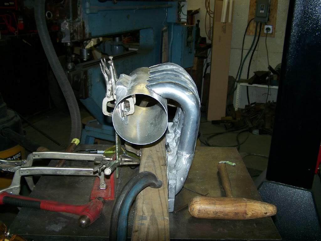
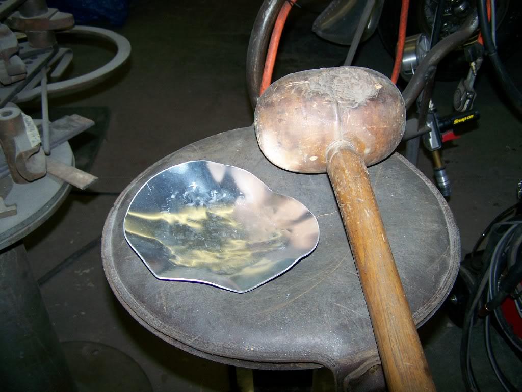
Here are a few of the grille being made:
This takes some olde-fashioned skills in metalshaping:
And of the grille installed. The fit is perfect:
As you can see, its a real piece of jewelry when its polished:
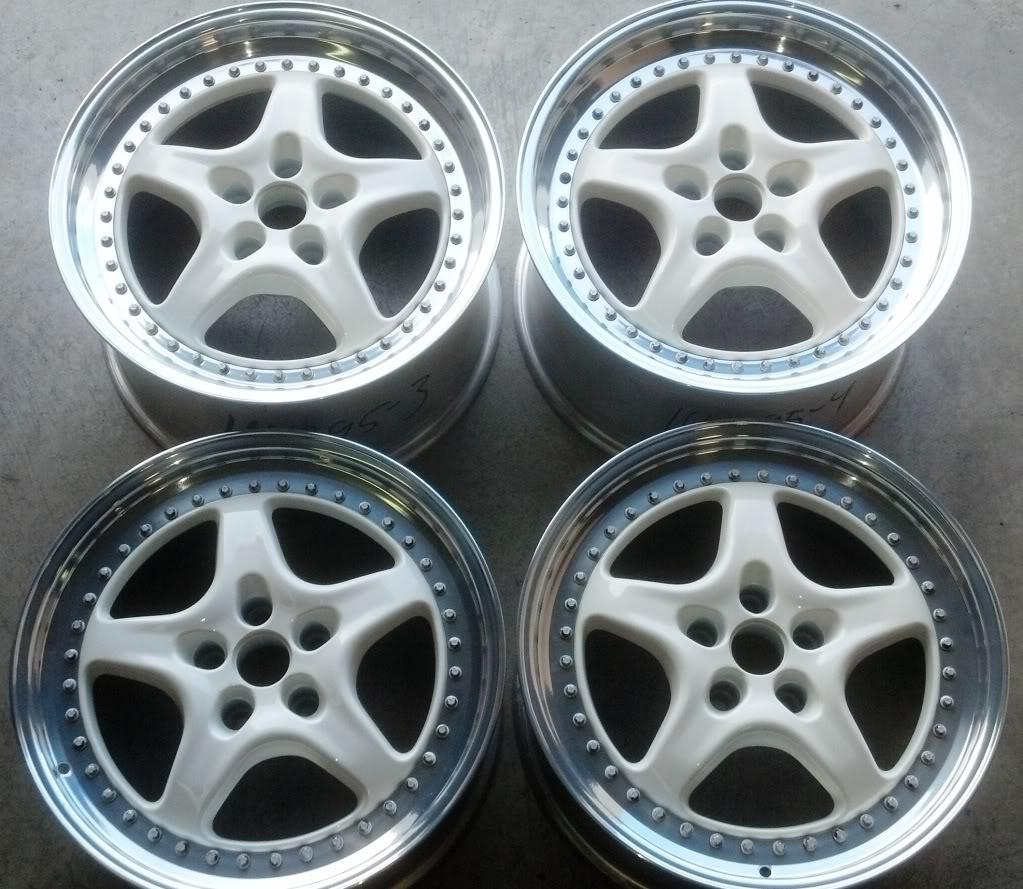
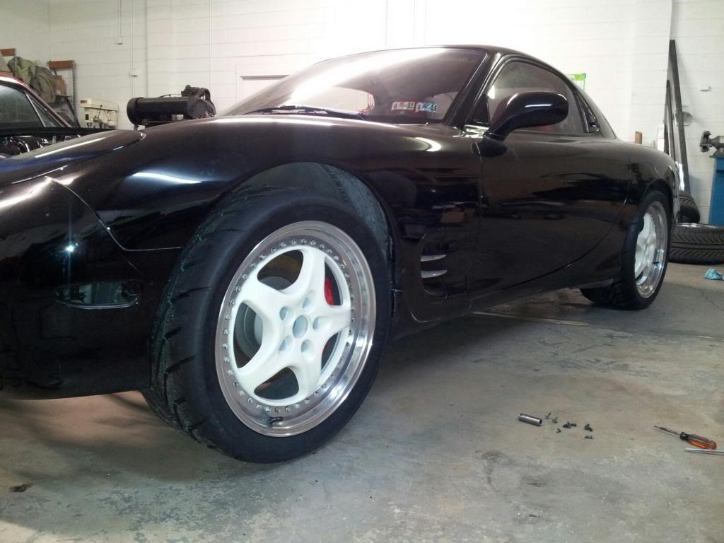
HRE 543R Wheels (17x9 and 17x10)
Generally, the most common types of wheels on FDs are variations on the 5 spoke designs and the basket-weave designs. I had several sets of 5 spoke wheels in the past and
have basket weaves on other cars. I really spent some time thinking about what I wanted on what was to be a more luxurious iteration of the FD theme and I have always said
the FD lacked those little detail touches or “jewelryâ€Â that so many fine cars have always had. The polished aluminum grille and valance were added as just such details and jewelry.
I thought about wheels the same way.
There were only so many manufacturers I really wanted to pick from including Fikse, HRE, and a few others. The wheels had to be made and finished in the best manner possible
and, while other manufacturers have some good-looking wheels, few have the level of design, craftsmanship, and finish I wanted.
I decided I wanted a busier look with more spokes. While the 5-spoke designs look more powerful and sporting, the designs with more spokes provide a lot more detail for an ex-
terior that, while gorgeous, is quite homogeneous. I looked at a number of designs and came down to the Fikse and HRE 10-spoke designs.
Here are the Fikse Aro and Mach V wheels I liked:


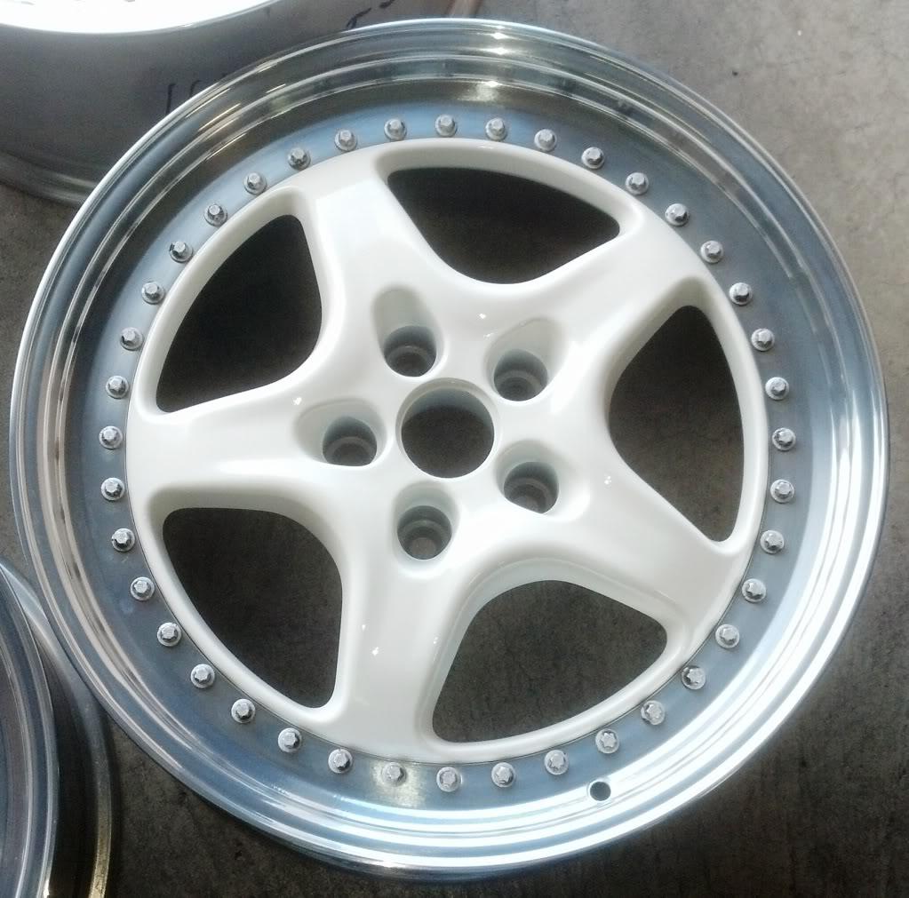
And here are the HRE type 543R wheels I finally selected:

I picked the HREs for several reasons. First, the curved shape of the spokes from center to lip is very close to the curve radius of the fenders. I believe theres a subcon-
scious link between the wheels and fender curves that you sort of subconsciously appreciate. Second, they are finished remarkably well and have the 3-piece design with the highly
polished nuts holding the pieces together.
The HRE's are like a diamond bracelet on my girl:

I think you can see how visually harmonious the spokes are with the fender's curves:

I guess I would comment that I have always liked 17 inch wheels over 18s, because I like having more rubber to cushion the ride and for the section to provide better warning of impending breakaway. I may try some 18-inch wheels someday just to see how they look versus how they ride and whether theres any handling issues. (This is obviously one area where I went way overboard and did not follow my own advice about not buying the most expensive thing in a least in this category.)
1-9-2011
INTERIO
Nearly everyone who has owned an FD for any time knows that the vinyl and plastic used in the interior are not first rate. The plastic or vinyl or poly-whatever that the doors and
other major interior panels are made of is very cheap looking and feels cheap to the touch as well. Many of us have fixed, strengthened the plastics, or completely redone them.
I did a complete job on my last cars plastics and knew starting this project that I wanted to completely remake the interior. I was going to remake the plastics, cover all of
the other poly-something-panels in high-quality leather, put in the best quality wool carpeting, and otherwise improve every element a component of the interior.
Leather-covered interior panels
I had a shop I have worked with in the past cover all of the interior panels doors, dash, rear quarters, console, hatch panel, hatch, and rear hatch sides and rear
in high quality black leather (Spinneybeck Sabrina as used by BMW). The only original panels not covered are the two small access panes on either side of the rear
hatch, I may remake these out of aluminum and cover them in leather someday, but otherwise you cannot add leather or the panels will not fit.
I chose not to add anything like contrasting stitching, because my intent was to keep the design the same as stock, but just upgrade the materials and finish on the
original design. This choice alone makes it very hard for anyone to notice that the interior is anything but stock.
The interior looks stock:

I love this photo taken behind the driver's seat. It all looks completely stock, but, again, it isn't. Everything is black leather (the same leather hides BMW uses), including the bins.
Covering the bin lids gave me the interior detail theme of "ribbing":

And I had them repeat the ribbing pattern from the bins in a few other places, like the subwoofer box in the rear:
The ribbing is also repeated on the drivers heel pad I had made and sewn to the custom wool carpet. Im not sure how it will hold up over time, but its ok till now and is one of the little touches I like about the interior.
Leather ribbed driver's heel pad:
The ribbed pattern was also used on the small console cubbyhole door above the radio. I doubt if everyone who owns an FD knows that this was how they came. Most FDs by now have had the whole area redone when better stereos were installed and few still have this little push-to-open door.
Ribbed pattern repeated on cubby door:

_______________________________________
Heres the ribbed pattern on the top of the interior quarter panel where it meets the headliner:
I think the interior panels took about four 50 square foot hides and the seats took 3
hides. So, I may have added 50 pounds to the interior from just the leather. (The
metalizing of the plastics added another 5 pounds or so and the carpeting adding an
as yet unknown amount.) There is an unexpected benefit from adding all this leather
and the much better carpeting. The inside of the car is much quieter than stock and
much quieter than the improvement from just adding sound deadening, which I also
added, as well.
__________________
Customized Spirit R Seats
The Spirit R shell seats are a variant of the 90s Recaro competition seats used on
Porsche and Ferrari Cup cars and are very light when not abused by someone like
me. I chose the R's, because they are the only shell style seat that was actually
designed for the FD and fits perfectly centering the driver on the tachometer. (The
inside -- the tunnel side -- of the seats are cut out and shaped very differently than
the outsides of the seats.) I like the fact that they are a tilting, fixed bucket design,
which is very comfortable, yet provides better than stock lateral support.
I also wanted to create a visual effect. I wanted the red leather bolsters and cushions
the fronts and edges of the seats to seem very thin and very red and the backs
of the seats to be black, just like the rest of the interior, so the seats would seem to
just be these very thin, very red seats "floating" in the all-black interior. However,
the shell is carbon fiber and the weave is yellow and black and very noticeable. From
a design perspective, its very busy to the eye and theres no way I could achieve the
floating-red-cushions effect I wanted with that carbon fiber on the back of the seats.
So, I covered the backs of the seats in black leather. The overall effect, especially at
night and with the red LED interior dome light on, is just what I wanted.
The original Recaro seats have a very busy yellow and black pattern...
__________________

SZo I covered the carbon fiber seat backs in black leather:
This shows the “floatingâ€Â effect of the red fronts in an otherwise black interior:

_______________________________________
The Spinneybeck Sabrina black and red leather used on the seats and throughout the interior is the same leather that BMW uses in its
high-end cars. (There is quite a big difference in the quality of leathers: clear hides, tanning and dying being most important. Also, the
price is per square foot and you buy them as hides. The problem is that you can seldom cut the pieces you need from the shape of the
hide and you lose leather and money in the process.)
I wanted the seats to be very, very comfortable and to resemble the original R seat pattern in design. So, I had them redone in leather
and with new cushions made in a pattern that resembles the R pattern. The foam is also upgraded from the usual in that there are
two layers of foam with the outermost being memory foam.
This shows the two layers of foam being shaped and glued up before being covered in perforated leather:
_____________________________
_____________________________
Heres an interior photo that shows the new perforated leather seats with more padding for my old bottom. You can't believe how com-
fortable these are, especially since they started as the RZ racing shells. I actually liked the Spirit RZ seats, but wanted something more
comfortable and luxurious while having more lateral support.
The interior looks fairly stock, though the materials give it a richer visual character :
_______________________________________

The leather is very nice and these are very comfortable seats:

(Continued in next post)
Transforming Interior Plastics
No one likes the plastic in the FD. Its been painted by some, fiber-and-duro-glassed, replaced, sworn at, painted with this or that rubberized coating and still no one likes it. I heard
of a company in Pittsburg that was plating plastics in metal: Pauls Chrome. I sent them all my plastic dash, console, armrests, vents -- and had them plate everything. What
they do is shoot silver dust into the plastic, so that it becomes conductive. Then, they can plate it, just like it was a steel bumper.
The console was "metalized in this way (shot with silver dust then copper and nickel plated) and then painted black. The ashtray was plated in copper, nickel, and then chromed.
(May be a bit much.) The short shift gearshift **** is a Voodoo aluminum **** that I had Joe Portas powder coat black with the shift pattern etched and filled in white.
I think the materials add a richness to the otherwise largely stock-looking interior:

This closeup of the ashtray is interesting, because, while you can see that the ashtray is chrome, you don't notice that the entire console is metal as well, but painted black or that
the area surrounding the console is black leather or that the seats are red leather:

Here's the same shift console area showing it just after being plated and painted:

After the copper plating, each piece was nickel plated as well and then painted black:

Even the plastic vanes in the air conditioning and heating vents were plated. I had them taken apart, and actually individually chromed and then reassembled. You don't notice
them very much, but you do notice them when you're driving it. The black plastic vent surrounds themselves are also metal plated and painted black:

Although there's plastic underneath, everything you see and touch is metal plated:

_______________________________________
Leather Covered Headliner
Ive tried a few different headliner revisions. First, I covered the headliner and visors in black mohair broadcloth. Seemed to absorb a lot of sound echoes and the stereo sounded
great. But it was really too claustrophobic in there, so I decided to redo the headliner and visors in perforated cream white leather. It may not absorb the sound as well, but it
really opens up the small cockpit and makes it seem airy by comparison to any black headliner.
Here is a shot of the visors:
_______________________________________
LED lighting inside and out
A lot of people have been converting their lighting to LEDs recently and I have done some of it as well. I have not yet wanted to add LEDs to my Knight Sports HID Sleepy Eye headlights,
though I have ordered some LED taillights. Ive played with it all a bit and have upgraded LEDs in the front turn signals (white), interior dome lights (red), and rear license plate lighting
(red).
The most interesting thing about it was the effect of the bright red LED dome lighting on the interior at night. I had planned the look of red shell seats sort of floating in an all black interior
and thought that the red LED lighting would make this effect really pop at someone looking at it at night. Well, it does and even better than what I had hoped. What was most surprising,
however, was not the cosmetic effect I had expected, but that the interior was now so bright at night that I can read every marking on my radio with the domes on. Its very soothing on
the eyes. Its great. Its like a fighter cockpit. You could drive with the domes on no problem.

1-11-2011
CHASSIS, STEERING, AND BRAKES
My Rx7 Evo GT20b is all about balance; making sure no one element in any area overwhelms the others or
does not fit and work well with all of the others. The brakes shouldn't overwhelm the wheels and tires. The engine
shouldn't overwhelm the chassis or the brakes.
When we talk about upgrading the FD's handling, we have to remember that the stock car was and remains one
of the finest handling, more extreme sports cars. The suspension on the car from the factory used squeeze-cast
A-arms and Rose-Heim joints. Nearly every tester at the time commented on how extreme the handling was.
How light and how stiff to the point of being bone jarring. So, you can upgrade the handling, often notably, but
it was already head-of-the-class to start with...
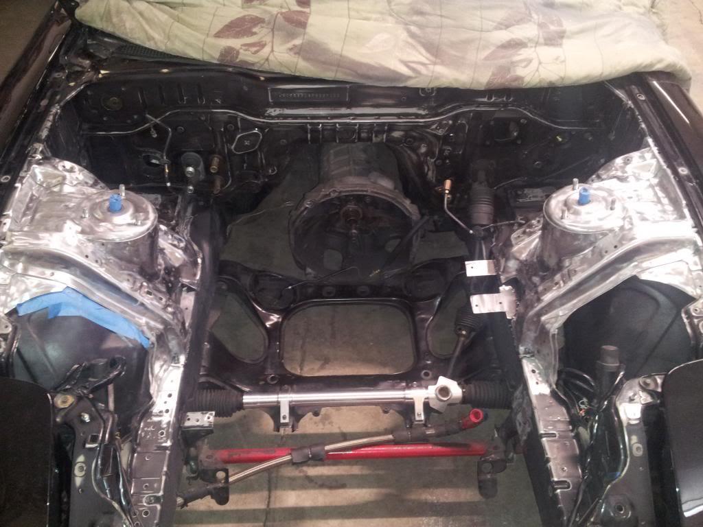
My biggest issue was deciding on what approach to take on the subframe needed to mount my 20b motor, so
that I didn't lose any of the handling the car came with originally. The problem is that the 20b doesn't clear the steer-
ing rack locating the motor on the existing mounts and there's not a lot of room. If you sit the motor up and in the
same fore-aft location as the 13b, the front end weight increases and the center of gravity moves up. You get worse
handling and often bump steer.
I had watched several people build custom front sub-frames to mount their 20b motors in a way that didnt affect
the handling or the steering. These custom subframes move the motor down and back a bit so the motor clears
the steering rack. No bump steer, the CG may be lower, and the weight distribution is stock-to-slightly-more-
rearward than stock.
While those are great objectives and they can be met this way, in practice, the sub-frames are difficult to make, ex-
pensive, require changes to the firewall, transmission, and sometimes the driveshaft. I decided to go with an after-
market subframe that doesnt require any alterations. There may well be some minor disadvantages
to this solution -- especially, perhaps, as regards the center of gravity -- but that is debatable at best.
_________________________
RxSpecialties Subframe
So, I could have made a custom subframe made that would lower and move back the engine or one that posi-
tions the engine less than an inch higher and doesnt require moving the engine back into the firewall. I chose the
latter from RxSpecialties in Canada. Theyve been supplying these subframes for years, they are extremely
well engineered and made, and have no bump-steer. So, while its possible to debate whether this solution is
optimal, I am fairly certain it results in as good weight balance and center of gravity as most FDs and was more
of a factory install with no effect on the rest of the car structurally or cosmetically.
(Since I made this decision in 2007, Defined Autoworks in Ohio has come out with a kit that relocates the mounts
and let's you use the stock subframe.)
RxSpecialties sub-frame next to stock subframe:

Subframe mounted on chassis:

_________________________
Zeal Function XS Coil Over Shocks, plus springs and sway bars
When I first upgraded my old FD, Peter Farrell Stage II had Koni yellow and some progressive rate springs. I later
went to Koni 2812 gas nitrogen race shocks paired with some 600-700 pound springs, harder bushings, M2 toe-links,
and whatever the PFS sway bars were. It rattled my teeth and just rattled. I didnt want that again and decided to up-
grade to more adjustable shocks that have lower pressure valving to suit the softer springs I preferred.
Zeal (Endless) makes several very nice lines of coil over shocks (as well as great brake products). Since my car is
not intended for more than street and occasional track days, I do not need endless (no pun intended) adjustments,
so I chose the Zeal Function XS series, with 6 way adjustable damping and a valving system that provides a very
smooth ride over a wide variety of speeds. I am using the front-adjustable Racing Beat sway bars and have quite a
few sets of springs.
_________________________
4.44:1 Ring and Pinion Gear
The stock 4.10:1 ring and pinion is well-suited to the stock motor and trans-mission ratios. Since my 20b NA mo-
tor revs to 9,000+ rpm and makes its best power from 5,000-9,000 rpm, I can really benefit from the higher torque
multiplication of the 4.44:1 ring and pinion, and lose little or no top end speed. (I seldom do 180 even on track days.)
_________________________
Atomic Rex manual rack
I did the looped line manual steering conversion on my first FD and tasted the feel that manual steering provid-
ed. I never tried the Maval manual conversion. When Atomic Rex came out with their new billet aluminum CNC-
machined manual rack, I bought the first one shipped here. Not only is there great feel, but it is also quicker at
2.4 turns lock-to-lock (versus 2.9). It is also much more precise due to the different rack design and better ma-
chining of the rack and gear, as well as the much more substantial solid aluminum mounting blocks to the sub-
frame. This makes a tremendous change in the way the car feels, the way it turns in; the way it handles
overall. [I am close to buying Atomic Rexs Electronic Power Assisted Steering (EPAS) kit that provides
assistance at parking speeds, since its a bit much on occasion.]
Heres the Atomic Rex manual rack next to the stock rack. Talk about hidden Bling!

Here is a picture showing the mounting blocks to affix the rack to the sub-frame.
The stiffer mounting increases feel and precision:

Heres the rack installed in the subframe:

_______________________________________
New Spirit R Brakes
When I started upgrading, I was still under the sway of Peter Farrell, so I bought his big brake kit, which was a Wilwood kit and a very nice upgrade. Later, I upgraded that to M2's
BBK, which had 13+ inch rotors and huge AP calipers and pistons. They really stopped the car right then. Quick enough that I briefly wore my seat belts.
The stock FD brakes are 11.6 inches (295mm) with 4-piston calipers in front and
11.6 inch rotors with 2-piston calipers in the rear and they were the quickest and shortest stopping brakes around. I think they held the record at the time or were second to Porsche.
You can buy 13 inch (330mm) front rotors and up to 6-piston calipers. I chose Mazda's own later upgrade to the Spirit R 12.37 inch (314mm) front and rear rotors with larger, diff-
erent, but the same number of, pistons. They are not the "best" or most expensive upgrade, but are great for my purposes, and I wanted this to be as much Mazda as possible, given
that its meant to be an evolution. One of the guys at Mazda USA got them for me and I m very grateful.
The new OEM Spirit R brakes, which have 314 x 32mm front rotors with stronger calipers with bigger pistons (~40mm) and the rears, while the same size rotors as stock, have the
rotors differently shaped and dynamically balanced with upgraded calipers as well. I like them, because they are larger and better designed and made, but still OEM Mazda parts. The
Brembo-like red calipers with the silver-white Mazda logo also fit with my color scheme.
The 4 colors I used on the car: black, red, white, and silver...
Carbotech Brake Pads
I chose the new Carbotech AX6 brake pads, which are an intermediate pad focused on autocross and acceptable for street, but not pure or serious race applications. Carbotech pads
are one of the best pads today and are made in America. The Endless (Zeal) pads are competitive, but are priced quite a bit higher for what is likely for me an unnoticeable difference
in useful performance. Stainless steel brake lines and a 929 master cylinder complete the braking system.
1-18-2011
First, I'm holding off about a week before starting on the engine section in order to get some good pictures. I'm going to cover why I did what I did. What it was when I started and what is is now. I'll go cover the intake, rotors, porting, headers, and exhaust. Then, I'll post several dyno graphs showing how the power corresponds to the changes made. The dyno testing won't be done for several weeks, so don't hold your breath.
Supernaut... Yes. I have drawn and even modeled several ducktail spoilers over the years and still think its the best looking in many ways. However, I cannot find any design I like better than the stock hatch without any spoiler. Arguably, the best lines on the car out of so many good ones.
Chudsoncoupe... Agree. The lip is part of a perfect curve that extends across the entire tail light group wiuth there being a branching "S" curve outward that defines the turn signals. Its also interesting that the designers seem to have somewhat purposely created a Kamm-effect tail, though the effects are not fully incorporated at the sides. The top 3 inches of tail light goes up and back (actually resembling a ducks tail from this perspective) and the bumper goes back quite some ways.
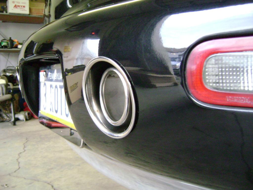
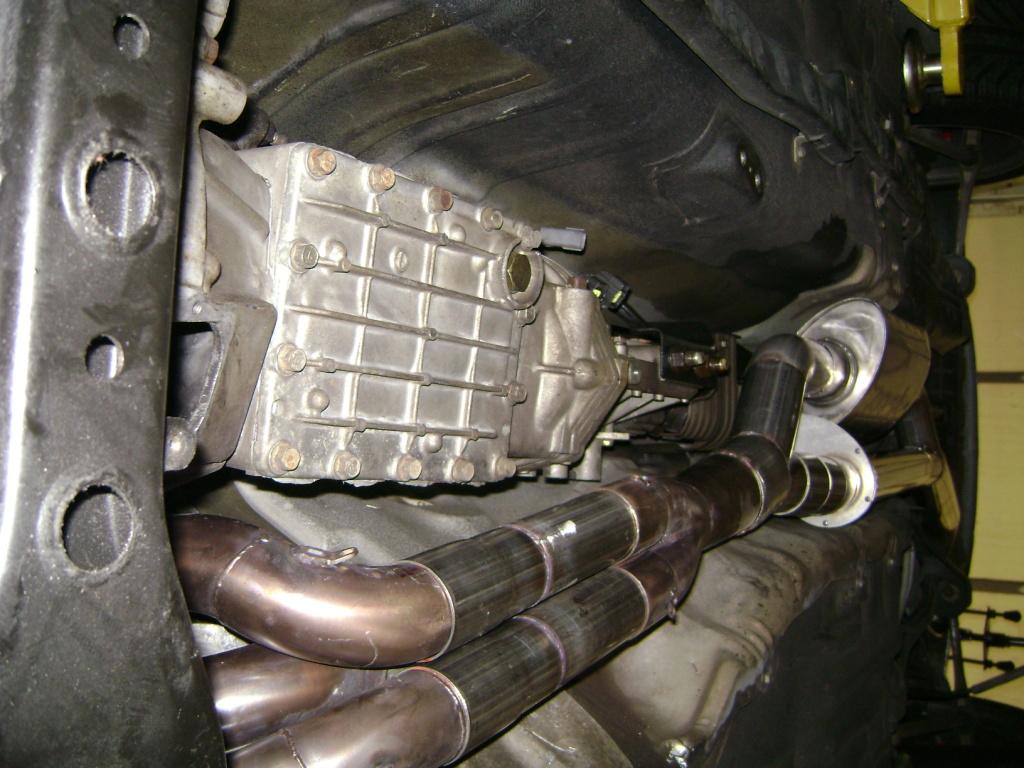
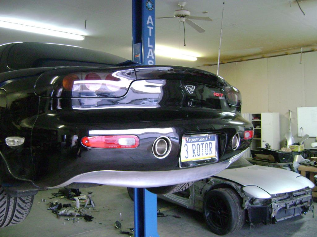
Dual Bumper-Exit Exhausts
I did decide to go through with my own exhaust treatment, though, perhaps in place of the spoiler. I guess I'll just show the drawings and describe it at least cosmetically. I have wanted a dual exhaust for a long time. That is, I have wanted an exhaust that has a pipe on either side of the back of the car. Not simply 2 pipes or tips coming out under the passenger side. However, until recently, I couldn't figure out how to do it without completely redoing the rear wheel well, gas tank and gas tank filler. I finally did figure out how to do it and here's how its going to look. (Before anyone says how ugly it is, wait until I describe it fully... ![]() )
)
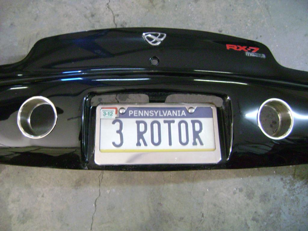
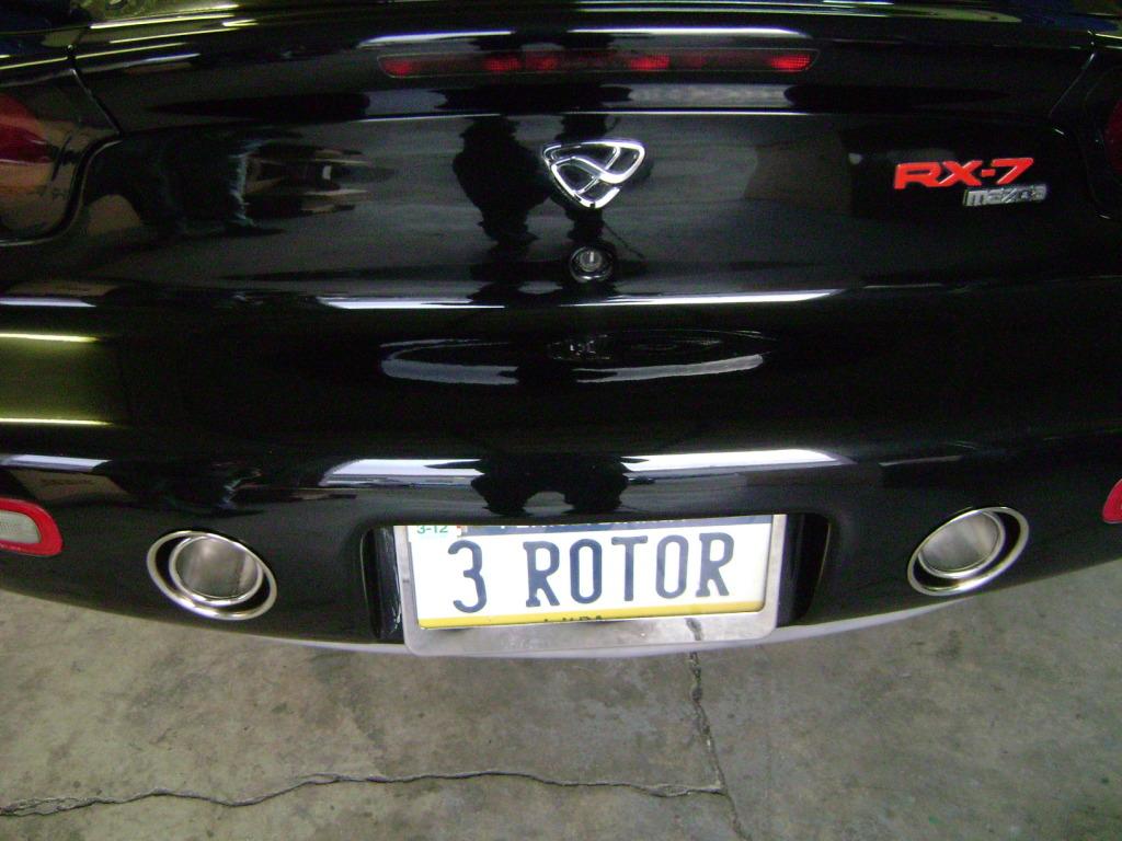
First, here's how it would look basically from directly behind the car. The tail pipes exit on either side of the license plate holder indentation and are at least for now, shaped like a rotor. They could end up being round, if I think the rotor thing is overdone back there, what with the new emblem.
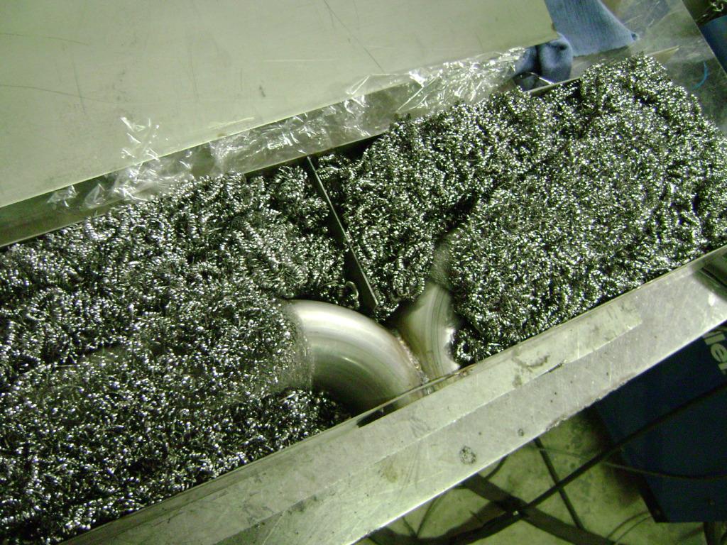
Here's another set of drawings that show how they are made and how it works. The exhaust outlets around the rotor shaped tips are aluminum and will be powder coated gloss black (or might be anodized black). The tips will be polished aluminum, but they won't extend much or at all beyond the black aluminum exhaust outlets... The exhaust tips come out of a 25x6x3 inch aluminum box mounted in the bumper skin in place of the foam and other hardware there. (It will be a structural part of the bumper.)
And, here's a quickly drawn overview of the exhaust system and how the exhaust gets into the aluminum box. There are 2 exhaust pipes and a side laker style pipe. The primary pipe works up to about 4000 rpm, then the secondary opens, and finally over 7500, the laker opens to exit to air under the passenger door. I do not think the secondary pipe will be able to exit from this box. Not big enough, I think. It might, but it will probably just end earlier somewhere after the Borla.

1-19-2011
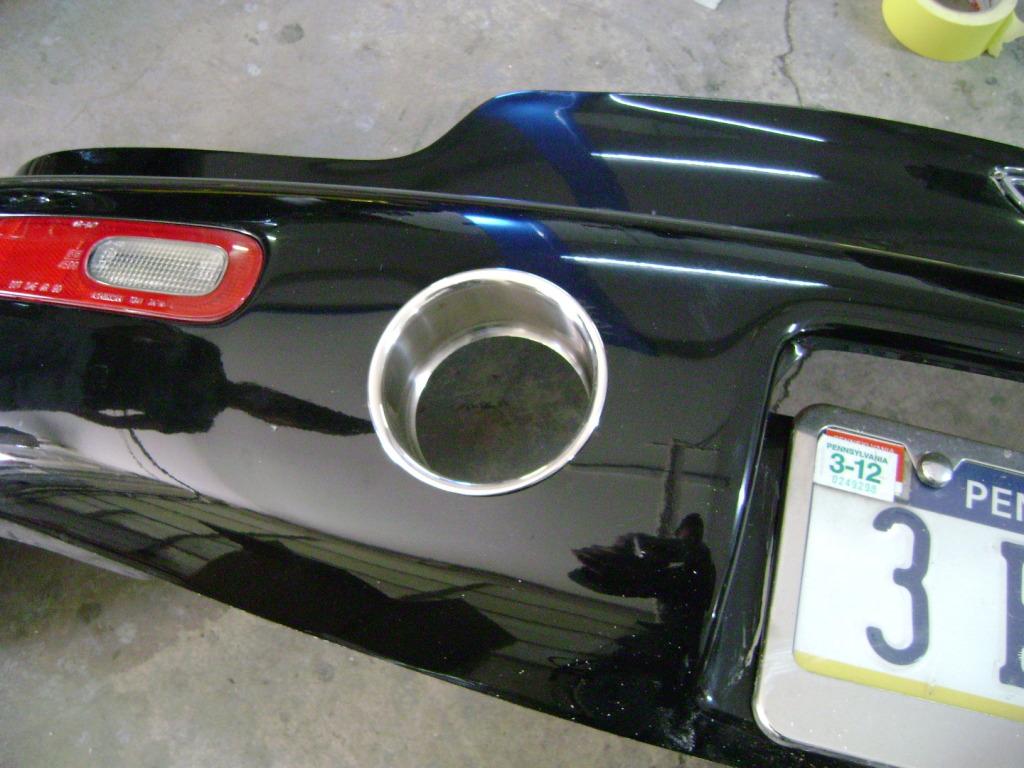
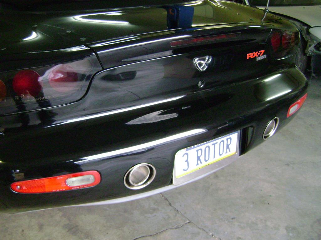
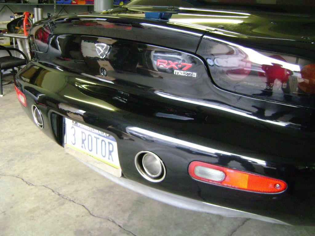
Here's an updated picture of the rear end with the round exhaust tips. Also, the exhaust box will need to be made out of stainless or some such to handle the heat and there will need to be some insulation added around it. Anybody still like the rotor-shaped outlets? I'm going with the round anyway, as much as I love rotors... ![]() I still have to overcome my need for symmetry, I suppose, but am thinking the outlets should be the same diameter as the 99 spec round tail lights. Looks like a good size...
I still have to overcome my need for symmetry, I suppose, but am thinking the outlets should be the same diameter as the 99 spec round tail lights. Looks like a good size...

1-28-2011
UPDATE SIDE VENDER VENT TREATMENT
Not much of an update. Everybody is waiting for parts or pieces of some sort to be made. Several things are close, but as we all know, it takes more time than it should. ![]()
Anyway, here are some pictures of the aluminum strakes I designed. This is one of the more controversial little projects I took on and so I want to say again that I try a lot of things and that not al of them make it. I've wasted a fair amount of time that way.
I designed 3 aluminum strakes for each of the two side vents. However, I designed them so that I could see how 2 strakes would look or how 3 strakes would look. I haven't polished them yet or decided whether they look good, but thought I'd put up some (poorly taken coming in out of the snow) pictures. The strakes fit into the vent opening perfectly and are positively mechanically affixed.
I think I like the views with 3 strakes...
Gordon
2 Views with 3 Aluminum Vent Strakes


3 Views with 2 Aluminum Vent Strakes


1-29-2011
I've tried many different treatments of the side vents, because, as you know, I do look for opportunities to add detailing that is suited to the design and doesn't go over the top. Of all the things I've tried, this has been the most difficult and most problematic. I am still not at all sure whether anything relating to the vents can be done that works for me. I'm still not sure on the strakes. I have only seen the pictures I posted and really need to see "the whole thing" before I will know what I think. If I don't like them, I have one or two other designs I've shown before (pasted below again) that I will try. I may end up doing nothing in the end. Or, I may like the strakes yet. ![]() I think one of the problems is that the vents are iconic to me. As designed originally, as I said earlier, its such an organic thing even though its mostly we owners that appreciate it fully. (Maybe a chrome mesh in there instead of the black plastic piece that everyone breaks or loses? What about an exact replacement for that piece out of aluminum or stainless which might shone more in there?) Anyway, I am hoping for a few more pictures from the front three quarters in particular. (I won't post those up, though...
I think one of the problems is that the vents are iconic to me. As designed originally, as I said earlier, its such an organic thing even though its mostly we owners that appreciate it fully. (Maybe a chrome mesh in there instead of the black plastic piece that everyone breaks or loses? What about an exact replacement for that piece out of aluminum or stainless which might shone more in there?) Anyway, I am hoping for a few more pictures from the front three quarters in particular. (I won't post those up, though...![]() )
)
The last things cosmetically are really something here (maybe) and the rear bumper exhaust outlets. I am doing these while we wait for engine pieces to finish the rebuild. If I hadn't changed the intake setup and added Logan's new headers (which he honestly believes add 30 whp), it would be done... So I might as well play with it now, since when the motor's done, its done until after Deal's Gap.
Gordon
This was the other major design theme I was pursuing. The problem is that you have to modify the vent insert and probably modify the actual fender there just a bit to make it look like the photoshop version below. If I tried this, I would just take out the vent piece entirely and cut away to of the fender behind it and put slat type vents like in the last sketch above that shows the side view.

Here is an overview of the stainless steel plenum or box that shows how it sits in the middle of the aluminum bumper crossmember. The plenum will be welded to the two side pieces that remain of the crossmember after the middle is cut out. The crossmember becomes a heat sink. DEI fabric will cover the inside of the bumper shell and there will be abundant insulation added all round.

This view shows the rounded shape...

Again, nothing is to scale, or exact, but here's how the exhaust pipe gets into the exhaust plenum.

2-1-2011
Phil... I agree entirely. However, I have tried a number of things that haven't worked and am thinking of just backing off it for now and come back with fresh eyes. What I have tried to do on every design so far is to have whatever I do fit with the existing vents and opening and the indentations on the door. What I am going to try next is to assume the vent piece is out and that I can cut away fender from the opening back to the door, if necessary. This opens up a lot of possibilities.
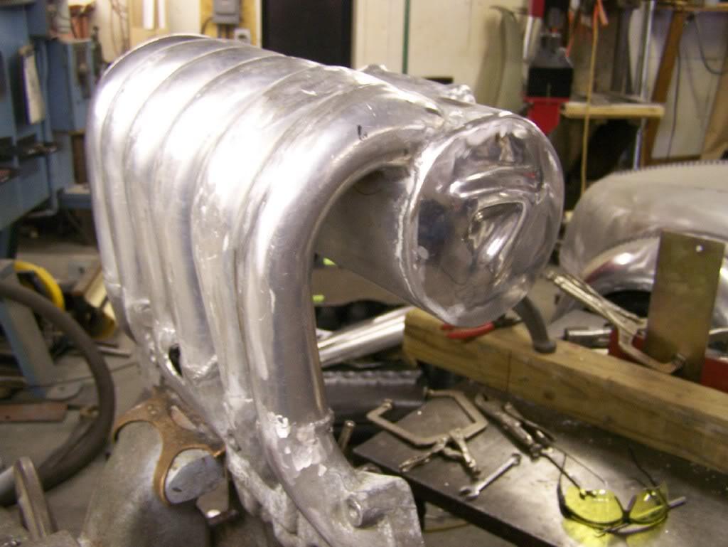
I also am getting closer on the motor. Te two things I've been waiting for are a new set of headers from Logan at Defined Autoworks and a new intake plenum and runners that I designed and that I am having made. The headers are quite a bit longer (1.5 feet plus) than my current headers, which should increase top end power by about (Logan's guess) 20 ft lbs. I think my intake plenum and runners will also increase power by a good deal, but I have no way of knowing how much. However, the plenum has more than twice the air volume from stock and the runners are longer and have notable taper to them for velocity. They are also a bit larger than stock in diameter over the length. Finally, they will be welded to the lower intake manifold cut off just after the (really bright) 90 degree turn into the port. The runners themselves are much better as they hit the sawed off LIM than stock as well, since the stock runners have to negotiate other parts attached to the engine.
The headers, plenum and runners should all be done by this coming weekend, so the engine goes back together next week!
Gordon


Here's an individual runner, showing the taper...

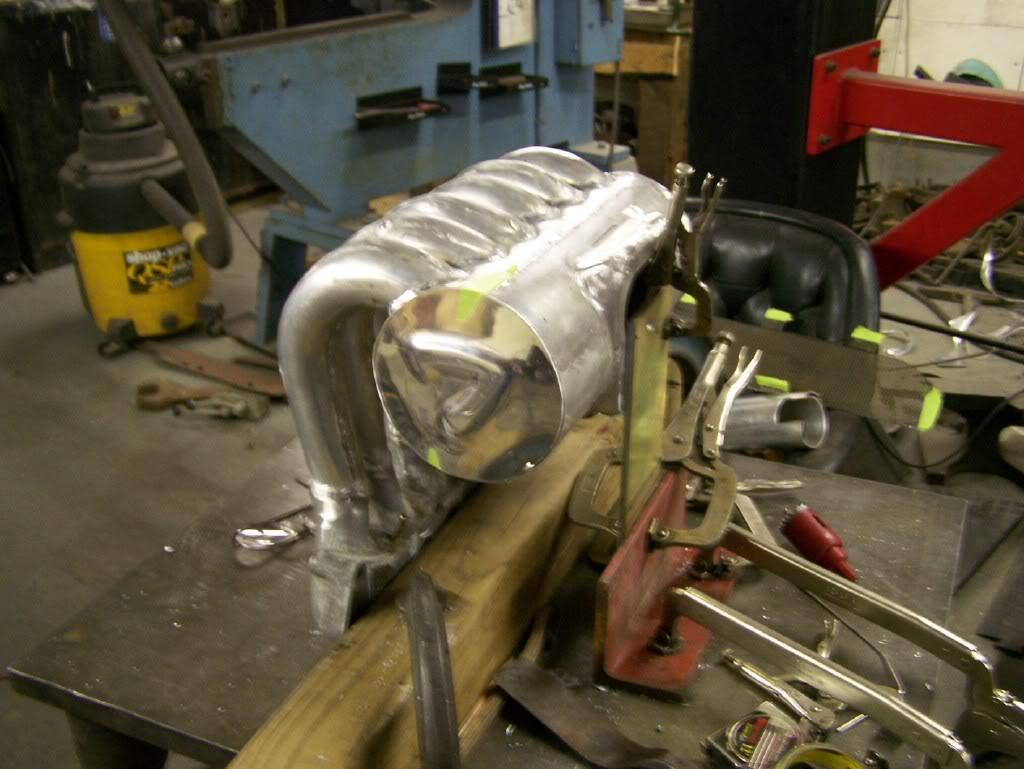
Here you see the flange for the 90mm throttle body.


Here you can see just how much larger the new plenum is compared to the stock 20b plenum. (When you're forcing air in, you don't care too much about flow... ![]()

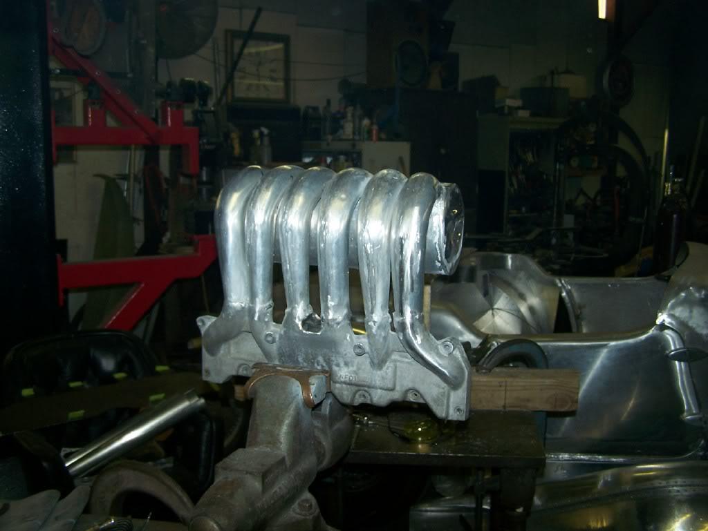
I thought I would post a few more of the intake plenum and runners. They are starting to take shape here. Just 3 more to go tonight!
Gordon


2-3-2011
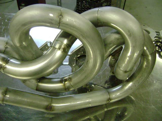
The pictures below show the rather painful process of making the runners. I didn't realize how many curves there were involved. Again, its the combination of the taper with the 120 degree curve that makes it tough. Here are the last 3 runners before being welded to the plenum.
Gordon


I'm getting excited. The runners are done. They now need to be ground and welded to the plenum. I should have the finished piece shortly.
Gordon

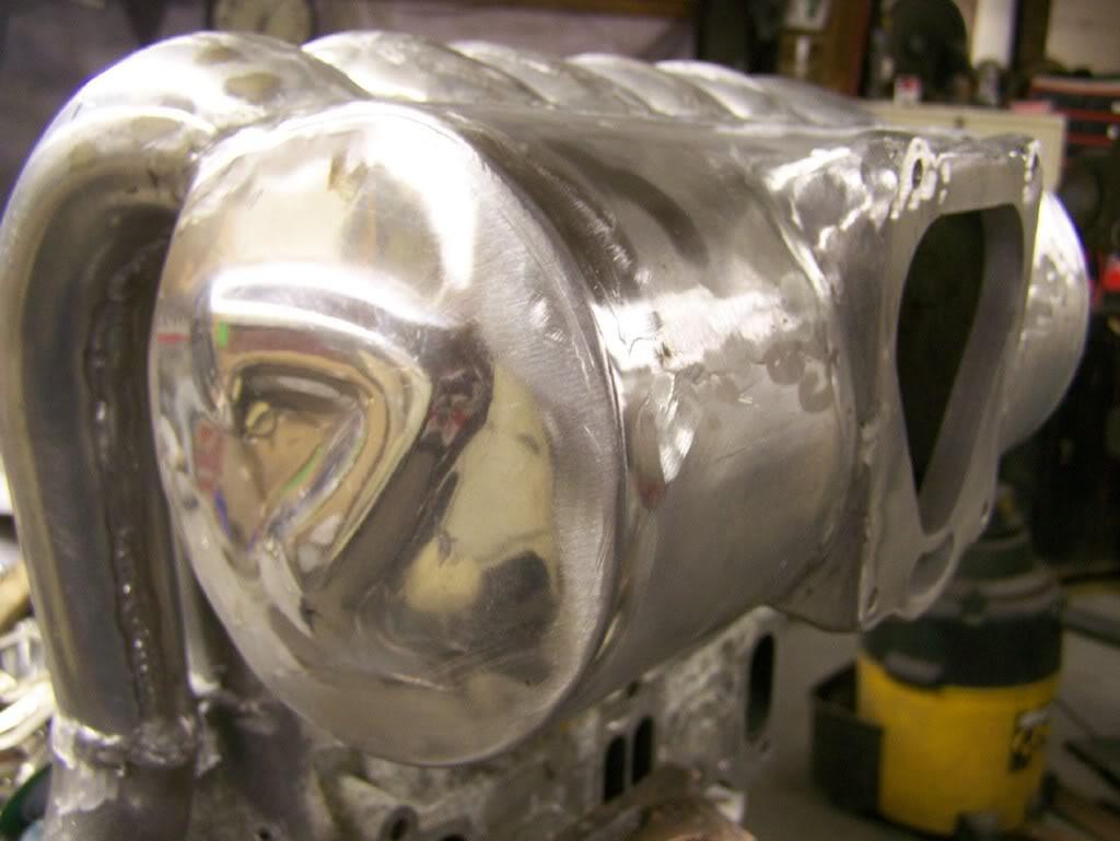
Ok... How many pictures of a manifold can somebody post? Well, its basically done. A bit more welding it to the LIM-flange and some grinding and its on its way to KDR tomorrow. Next pictures will be on the car!
Gordon
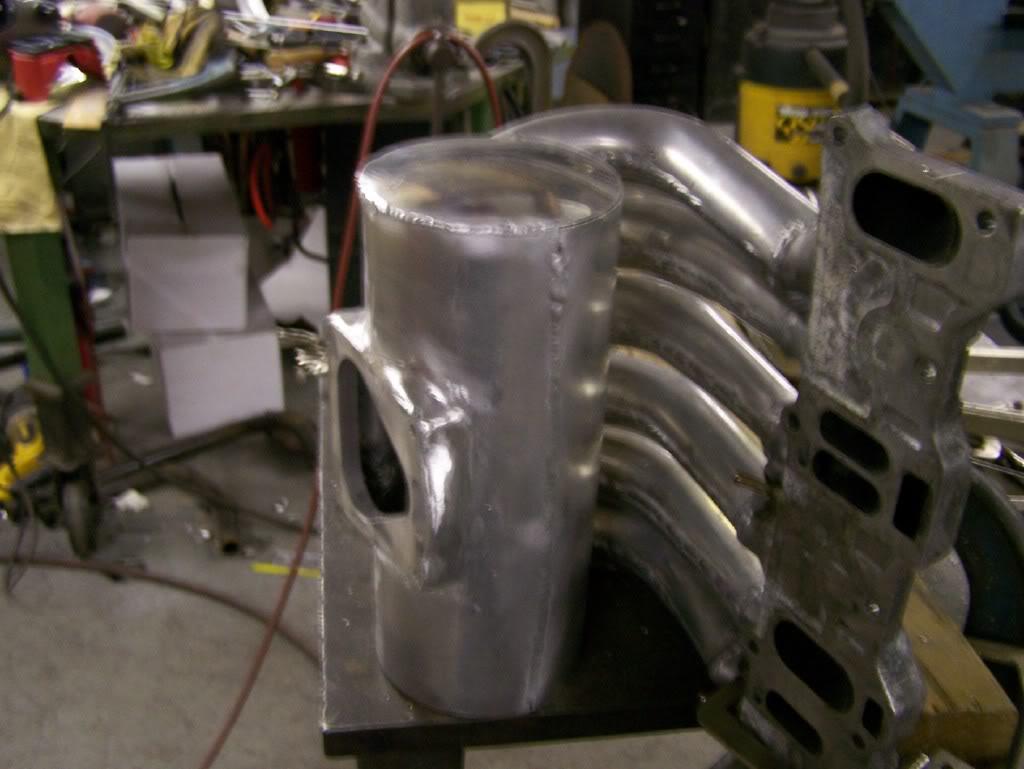
To get an idea of how much bigger and how much more air this thing can flow over the stock 20b UIM, here's a photo of the new plenum with the stock 20b manifold behind (inside of) it.


Victor can't take still photos very well...
This shows one of the runners having had the welds ground off, but not polished...

2-4-2011
So, here are a few more pictures from this morning. The runners have the welds ground down and he is now welding the runners to the plenum and LIM-flange. You can see the differences -- and similarities -- here between the original stock intake and the new one.
Gordon


2-5-2011
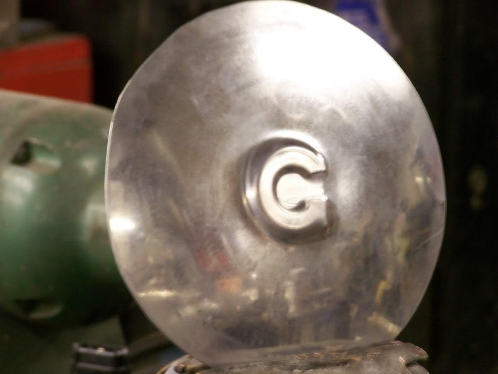
First, my guy welded 5 of the 6 runners to the plenum and is calling it a day. Tomorrow he will finish the last runner and put on the 2 end pieces. I am going to try to get him to emboss the "7" from the emblems he's making for me. He did a "G" on the first ones he showed me (below as well). The ends will be close to a semi circle on each end.
Second, I have the first pictures of the new headers that Logan Carswell (Defined Autoworks) built for me. I'll put those in the next post...
Gordon

Here are some pictures of the first versions of the end pieces. I haven't seen the new ones.

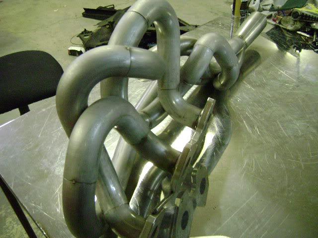
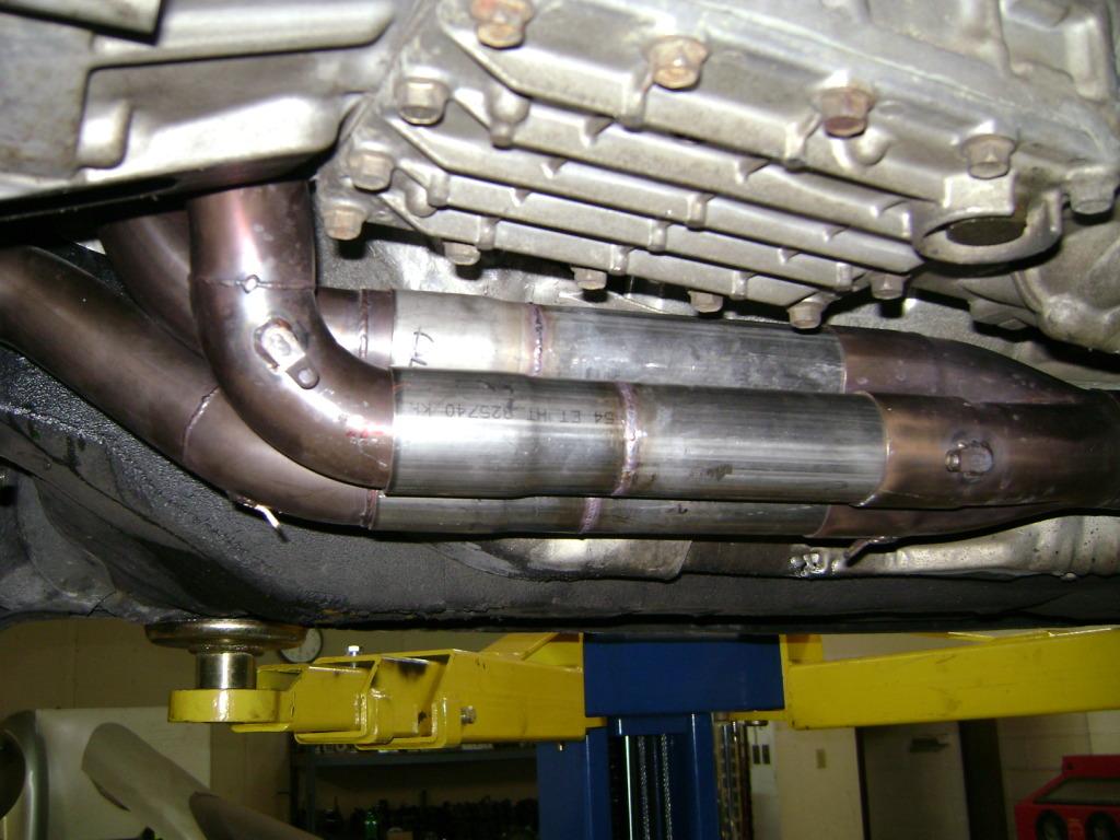
New Headers
Its hard to figure out which to show first. I didn't have a lot of build pictures, so I think I will just show the headers off by themselves as almost finished. They will be ceramic coated a battleship grey.


2-10-2011
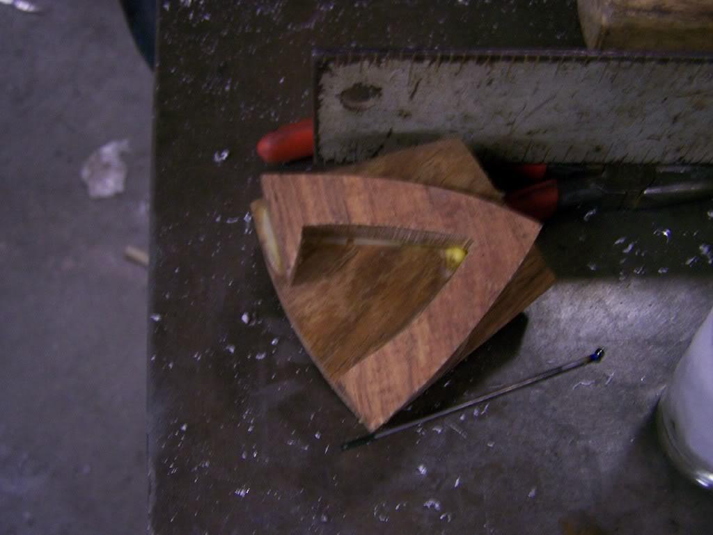
Haven't gotten the final pictures of the plenum yet, but have a few that show the plenum being finished. He is still working on the end cap on the plenum, because I got silly and decided to have him emboss a big "7" on the front (end) of the plenum. I probably have a picture of the wooden "7" he's using to emboss the end cap.
Gordon
Here's the buck he's using to emboss the "7".
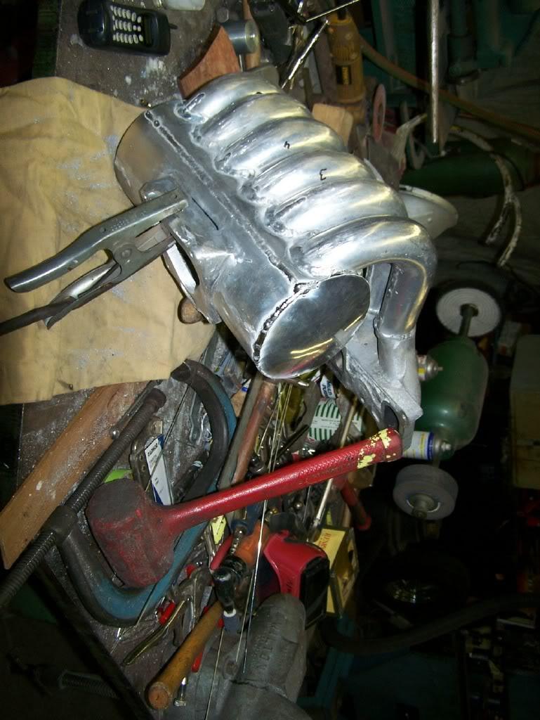
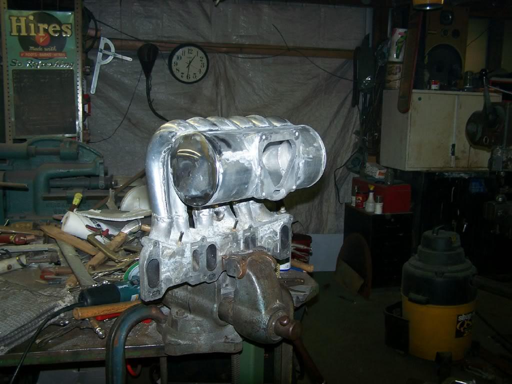
And, ere are a few shots of it almost completed, but some grinding and polishing to do.
2-11-2011
Here are a few pictures of the front end cap for the plenum. I had Vic put a "7" on the end cap. He should have it all welded up and then do the grinding today.
Gordon

The plenum and runners are done (minus final polish after testing). The marks from the grinding areas really need some buffing to get the full effect. The dull surface areas are like camouflage paint on a battleship. I know a lot of people are looking at the thread without commenting, but I would really like to hear any comments on the "7" I put on the end cap. Just curious...
Gordon

2-12-2011
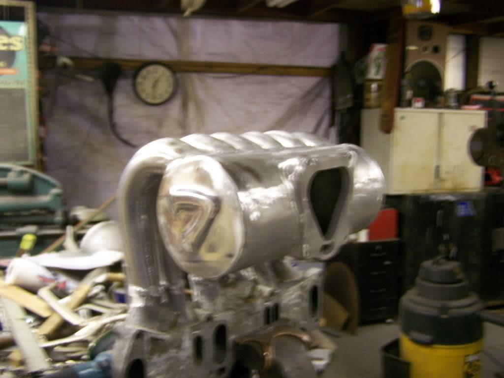
Here is a version that has the sides of equal width...

And here is a version that shows the sides of the 7 narrowing a bit...
[
Josh&FD... The flash IS effecting the way it looks, but it was "soft" because I wasn't entirely sure about doing it at all. (I could have had him use the female mold and it would have been way crisper, but had him use flat rubber for the female and pressed the male into it with a 50 ton press. As I said to KKM, I may try adding a fairly thin and small 7 to the top of the embossed 7.) Right now, my car is badge-ess, so this is its current 7 badge, I suppose. ![]()
Josh, Thanks very much for the comment. Although I haven't seen it yet in person, I think it may be too soft. These two pictures may show that its a bit more defined and pronounced than the other pictures show it. My best guess from the pictures is that the 7 comes out about a half inch and the ange looks to be 65-70 degrees. So, I am somewhat hopeful still, but... ![]()
2-25-2011
The headers were designed using state of the art formula and of course has a burns style collector, as did the old one. The math-derived lengths were then shortened a bit retuning them and running the dyno iteratively. The three header pipes each varies a slight bit from the others in length to accommodate the change in the speed of sound waves as heat increases and the three 20b rotors each have different exhaust port heat. Also, while I don't remember the name of the metal Logan used, it is not a common stainless steel. It has some mineral impregnated in it that in some fashion keeps the heat inside. An advanced header material. These are the second set of headers I've had made and if they do what I think they will do, I will either leave them as is or ceramic coat them and be done (I truly hope).
We haven't considered variable volume plenums, but have thought about variable length runners. We've thought a lot about the fueling issues from low to high rpm and, while our focus on this motor was the broad torque curve and peak power at 9,500 rpm, we are thinking we can balance things out with Paul Yaw's ID1000 injectors in conjunction with the high speeds the primaries should achieve through the taper and length. The biggest issue we had was the 90mm throttle body opening and getting the fueling when it opens to increase in lock step with the sudden gulping. Using one of Yaw's 1000cc injectors per rotor let's us achieve very accurate control over the entire rpm range. We also went from the 10:1 Rx8 rotors to S5 NA 9.6:1 rotors, because we are pretty sure that the physical squish area (or scallop or dish) on the 10:1 rotors is just so shallow, we think there was a physical fueling issue at higher rpm.
Its all down to putting it on the dyno on March 5th and seeing if all this accomplishes what we set out to do or if its back to the drawing boards. I've started writing the section on the engine and only have written about what I wanted it to be and why. What I've been trying to do, as I think you know, is build a motor that makes about 350 whp, has bags of torque everywhere, and makes peak power at 9,500 and goes strong to 10,000 rpm without either peripheral ports or individual throttle bodies. I am pretty sure that no NA rotary motor has done that before. Anyway, I am hopeful the new headers, and the intake will get me there.
I don't know if you've seen the new slide throttles that Logan has made for his car and Chris Walker's, but these are the state of the art and should be equally useful for 20b turbos and in 2 hole form, 12a's and 13b's. We are going to make up a variation on this new design for my car on the next plenum go round.
(I have been tempted to bump that 2008 thread "Predicting the future". While I was off about a year or so, Bernanke's intervention on the short end of the curve was unprecedented and delayed things. Combine that with Obama's masterful handling of the middle east and oil price increase and the related increases in the Treasury curve ensure high inflation. His masterful economic policies manage to increase the costs of doing everything and he scares the hell out of every sane businessman. Volatility thy name is Obama. Little or no GDP growth for the next two to four years. No job growth. Anyway, stagflation, late-ish...![]() )
)
3-25-2011
Some guys were over at SpeedOne (aka KD Rotary) sometime this week and took a few more quick vids of the car on the dyno with the new headers. (Everybody else gets to see it, but I haven't even had time to get over there. And, no. I don't know why the videos look a little green-ish...) Thought I'd just post them up. Nothing to report yet for numbers, since it now only has 21 dyno-miles on it, but I'm going to pick it up Saturday and put 200 miles on it to get the RA seals bedded in more. Its just too slow on the dyno.
Gordon
http://www.youtube.com/watch?v=ceOeV...eature=related
http://www.youtube.com/watch?v=NX-vq...eature=related
3-31-2011
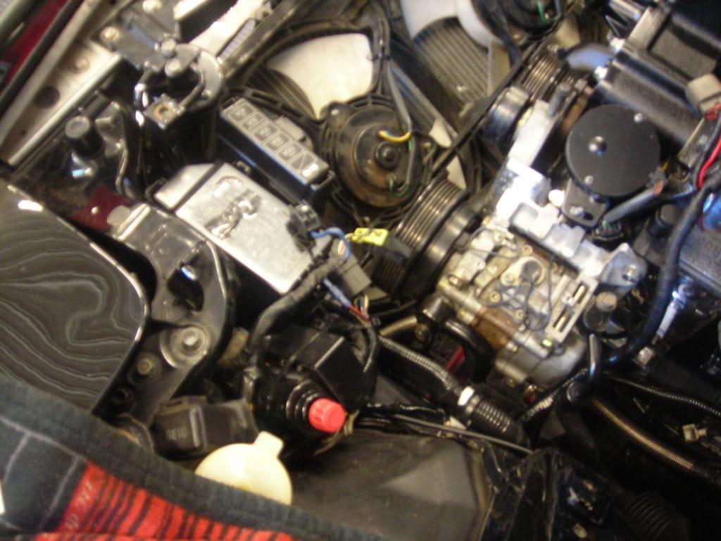
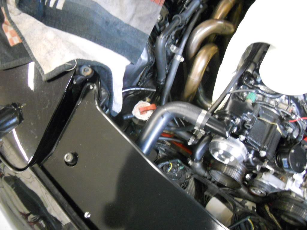
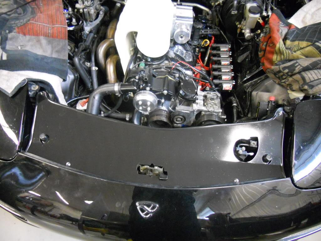
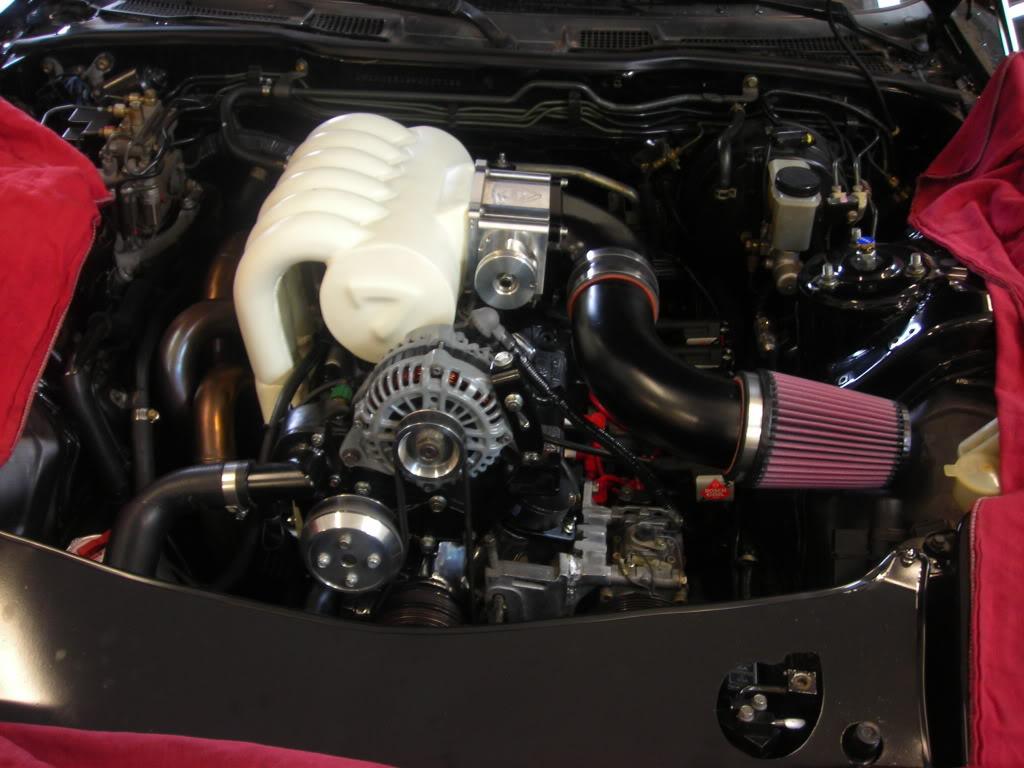
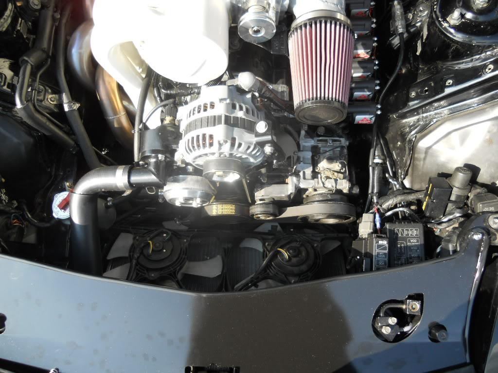
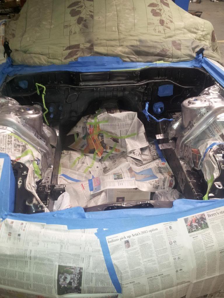
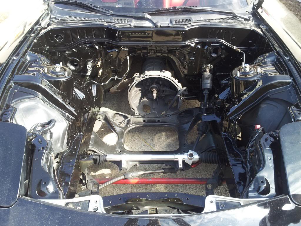
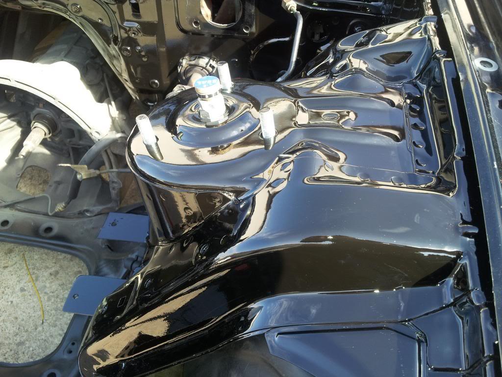
We're still finishing up the engine bay and getting the powder coated plenum and runners, throttle body, and air intake back on over the next few days. Then, I finally put a few hundred miles on it and we tune it one last time before Deals Gap. Here's a few pictures showing the simplified wiring harness that really can't be seen and the relocated fuses and relays away from the driver's side fender. The shroud should be on and the coils relocated tomorrow.
Gordon

4-9-2011
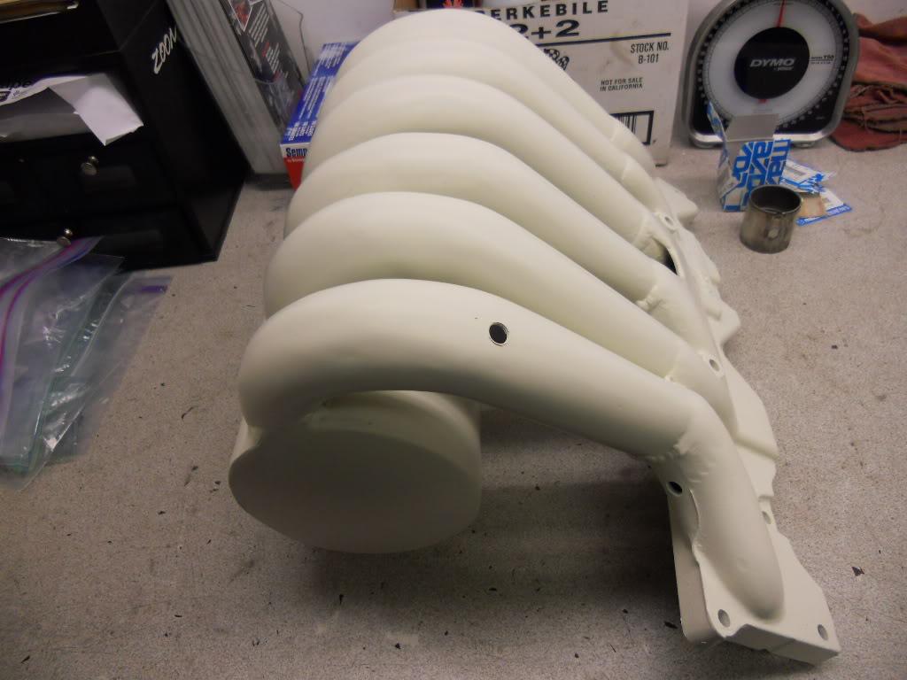
Christ... Just trying to get the plenum and runners powder coated and painted was an odyssey. The guy said he could do it in 2 days and it took 14 to actually get it back. Hopefully the engine will be back together in a few days and the engine bay cleanup completed. Here's a couple of pictures of the plenum. I still haven't even seen the car with the motor in and together, though some people have posted some videos. Oh, well. Looks like its still done in time for DGRR.
Gordon


4-11-2011
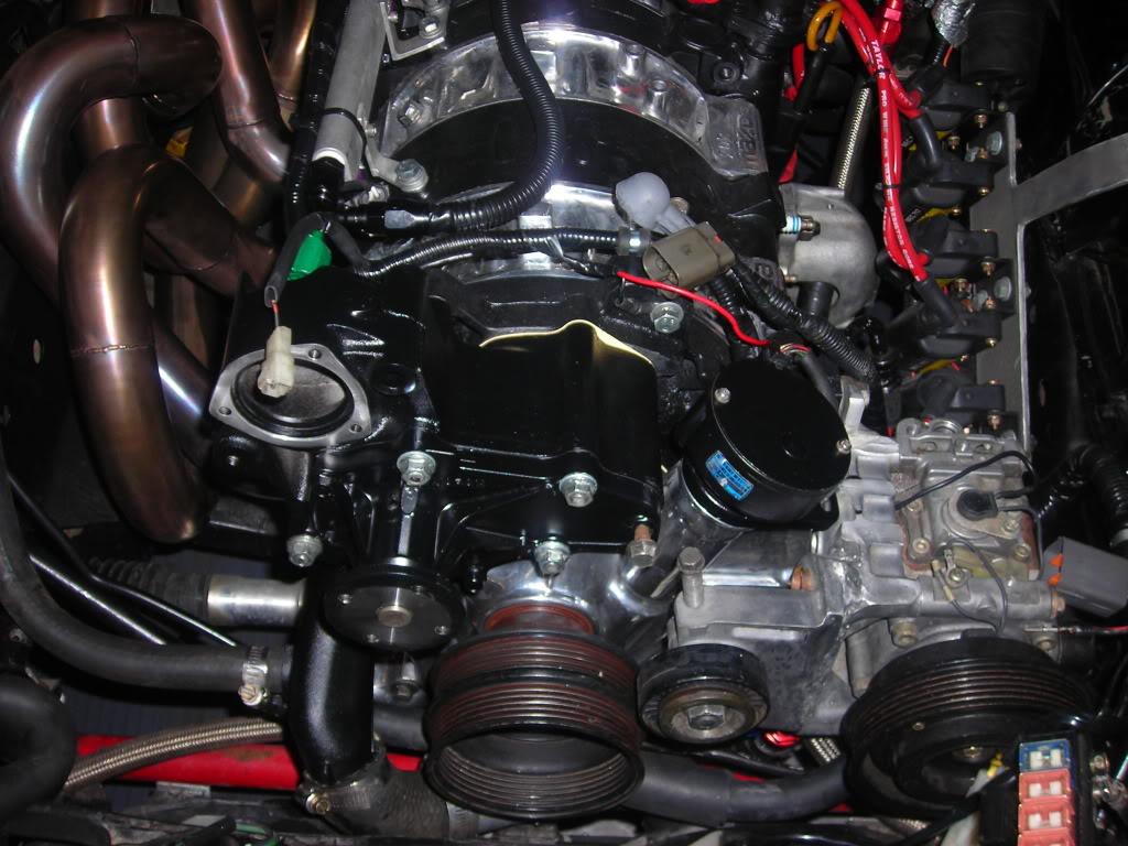
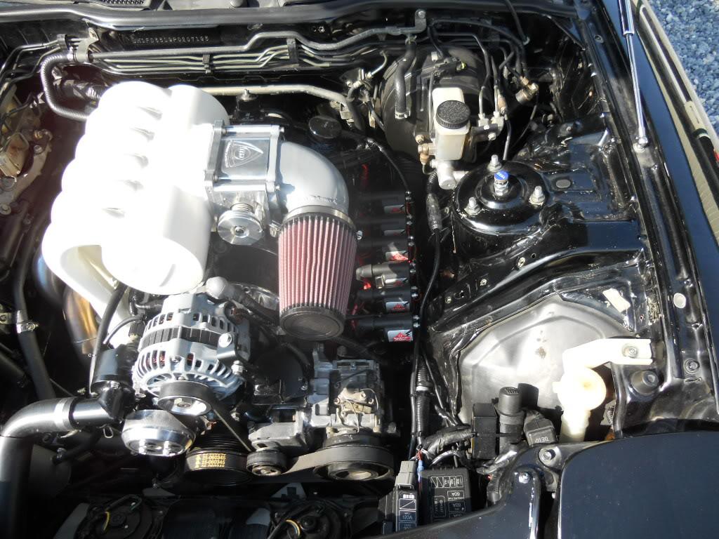
Well, the Speed1 guys (everybody knows that's KD Rotary, right?) are getting the engine back together and the last of the engine bay clean-up done. Here are a few pictures they sent tonight since getting the plenum back.
Gordon
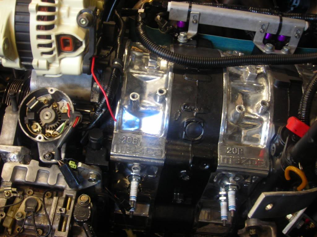
First, here are the relocated Bosch coil packs. You can see that the relays and fuses on the driver's side fender have been relocated. Its pretty clean now.
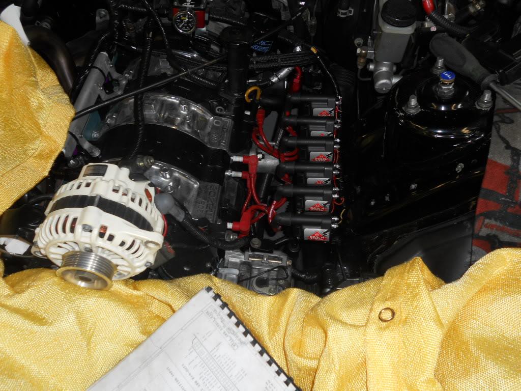
Here's another picture of the coil packs from right above. With the fuses and relays gone, its way much more easy to get at the plugs and coils.
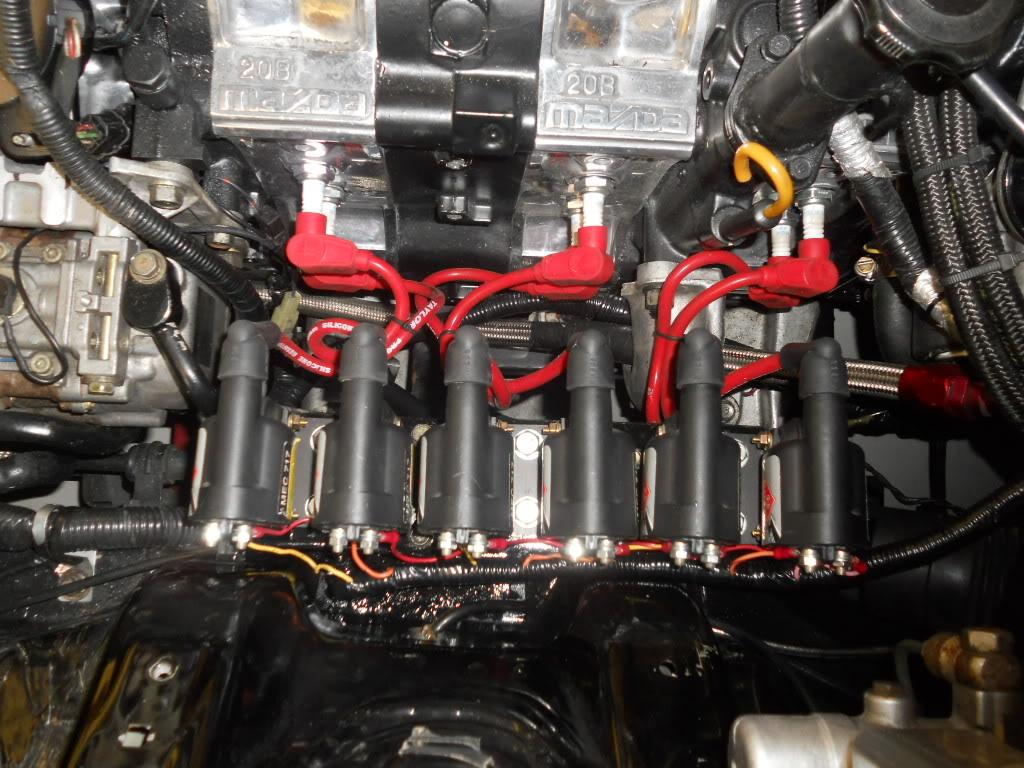
Here you can see the plenum on all the way down into the coils. The alternator cover is going to be replaced with a black or natural finished one (does anyone in the northeast have an extra alternator cover that's black or the natural finish, or even gray that they could send me to try out for color?)
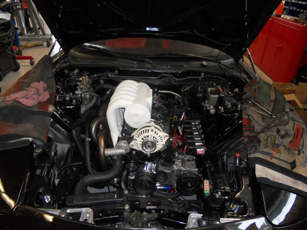
Again here are the plenum and coils.
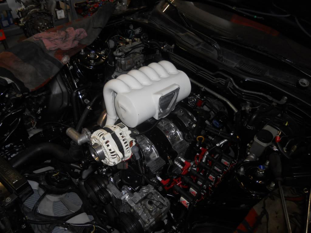
Here's another.
4-14-2011
A few more pictures as it comes along. Should be done tomorrow or so.
Gordon
Gordon
4-21-2011
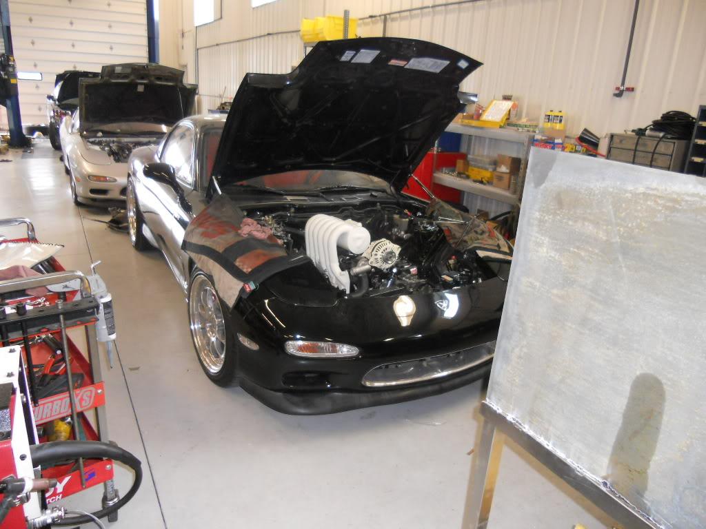
Okay... So, I'm done with the engine bay clean-up except for the intake setup. I still haven't decided how to do that. The choice is between a traditional pipe going down to the grille in front or cutting a duct in the hood and bring forced air directly into the throttle body. The piping would be cream colored and I think it will balance the cream on the plenum and runners. Not going to get done by Deals Gap next week. Will do that over the summer along with the exhaust. So, here are a few pictures.
Gordon
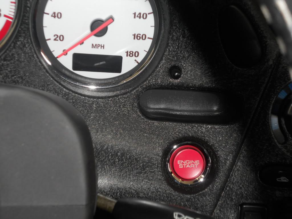
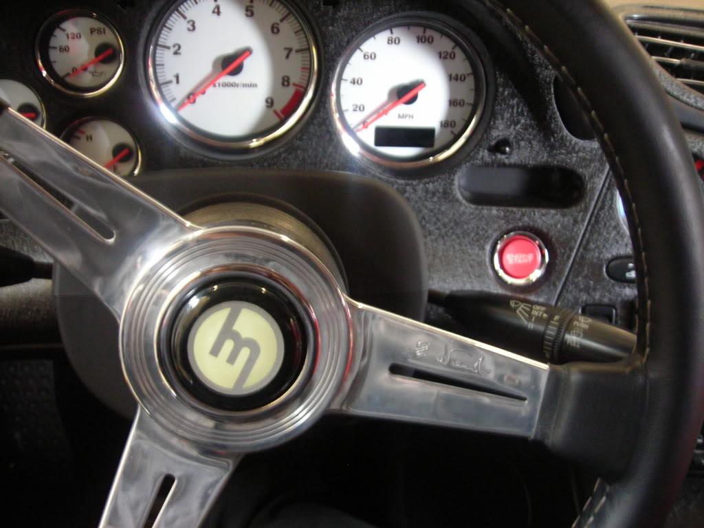
First, I added a Honda S2000 "start button" to give myself a little startup drama... ![]()
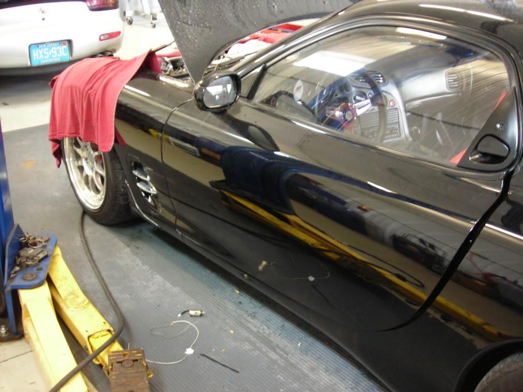
And, here's a couple of rainy day shots of the strakes on the fender vents...
Here's the engine bay with the temporary intake pipe and filter...
4-25-2011
I have an old school Mazda "M" logo horn button (thanks, Rich) on my Nardi wheel. I liked the look so much that I decided to have a shift **** made to match the horn button. The guy (Landon) who is making shift ***** out of plastic or acrylic poly in the vendor classified sections is making it (them) for me. Anyway, here's the horn button and some photos of the new shift ***** before he puts on the "M" logo. I should have the finished ***** this afternoon and will put up some pictures of the finished ***** then. (Landon does beautiful work.)
Gordon
Here's the horn button...
4-25-2011
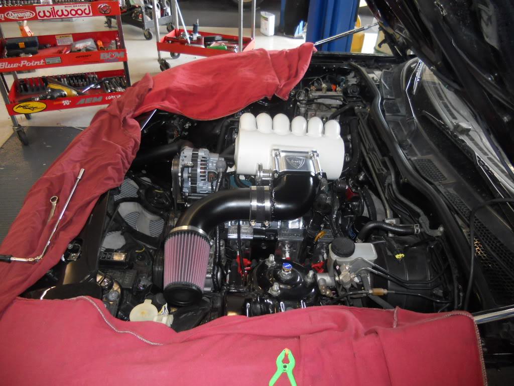
I changed the intake piping and filter location. Its still temporary, but I think it looks much better. So, this is it till later in the summer. Only thing is that I need to get a black K&N filter wrap.
Gordon
8-24-2011
Then, we rebuilt the engine, but, with me always trying to "improve" things, I decided to go back to the lighter 10:1 Rx8 rotors. We ported it a bit more as well. We got it back together with the new plenum and Logan's exhaust and put 600 miles on it. Then, we started dyno work. Immediately, it became clear that the 10:1 rotors were now a problem. The higher compression rotors interacted with the bigger plenum and created a pulse wave starting at about 6500 rpm that sounded like a pulsed wailing. The rapidly changing air velocity as a result meant you couldn't tune it at all over 6500.
So, I had the choice of rebuilding the motor (again) with the S5 9.6:1 rotors or taking the bigger plenum off and replacing it with the much smaller stock plenum for the time being. I didn't want to rebuild the motor again for no good reason, so I switched to the smaller plenum and, voila, no pulse waves. However, no air volume at high rpm either. The motor runs out of air at 7500 or so, but runs great up to that point. The lighter eshaft and rotors mean the motor revs an awful lot faster and it really runs beautifully from 0-7500.
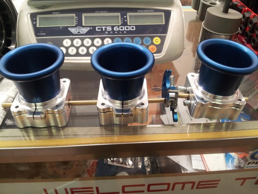
However, we need to solve the intake problem. Again, I don't want to rebuild the motor and go back to the lower compression rotors. I think I was right initially that they are the better choice. So, we have ordered some 52 mm Jenvey throttle bodies and will be stuffing those in there in October. I really wanted to keep it simple with a big single throttle body and plenum, but this is really the more reasonable choice right now. It means I will get the maximum power possible from the motor without any air flow constriction, though it will be a little noisier. That's ok.
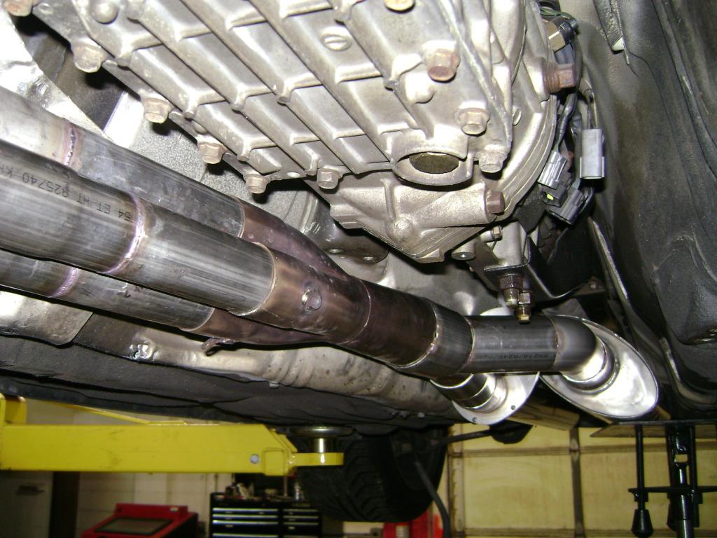
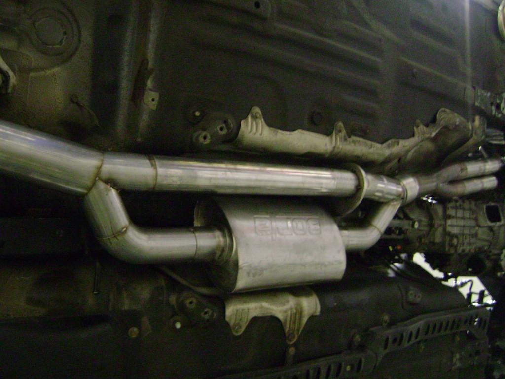
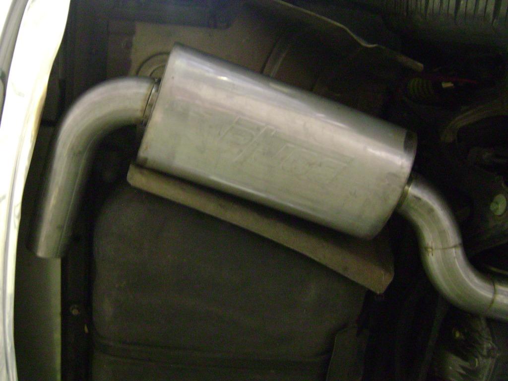
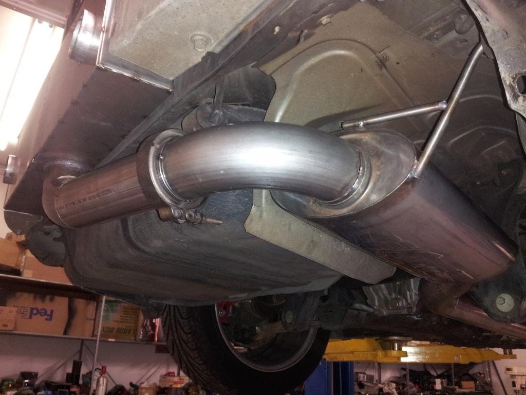
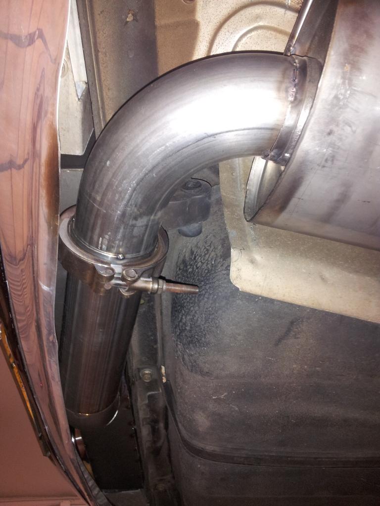
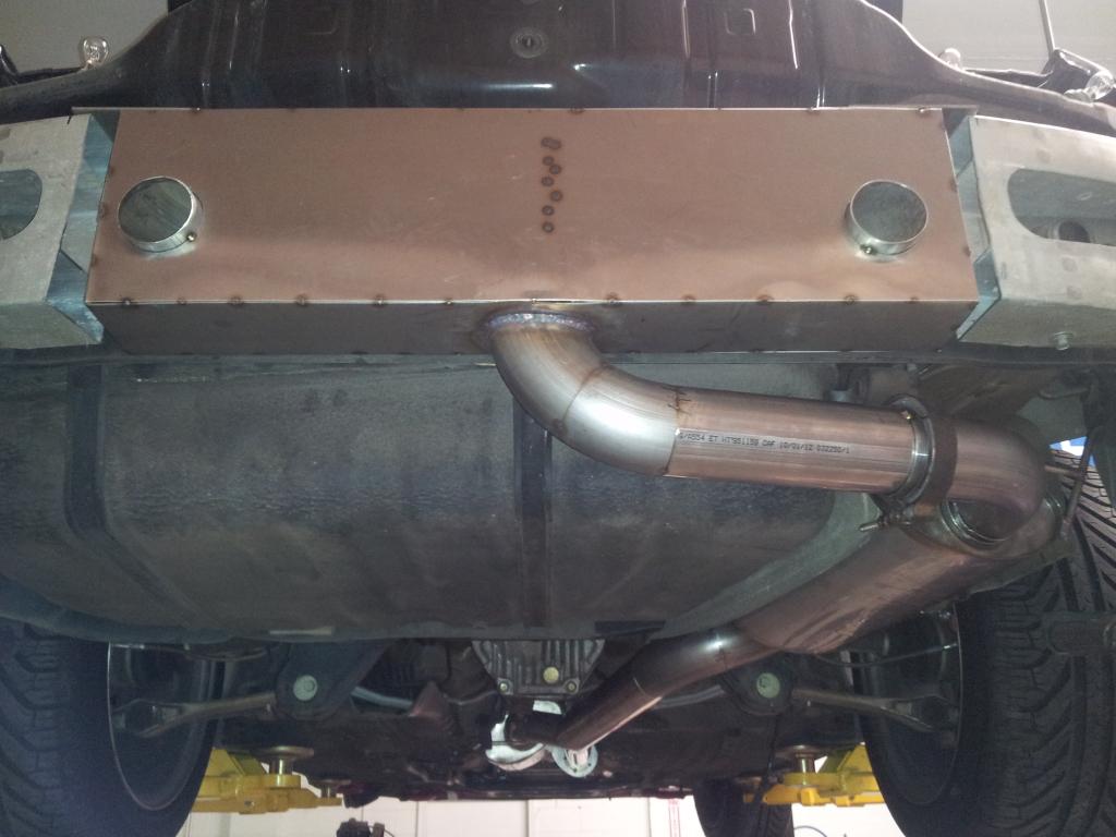
The last thing we are doing is installing the new exhaust. It was supposed to be done before the Carlisi meet, but Barninger has been so busy that it didn't happen. We have all the pieces and it shouldn't take much to get them on, but the programming will be a challenge. The exhaust consists of a reducer from 3-to-2.5 inches off the collector going into a 2.5 inch Y-pipe. The one side will go into a 2.5 inch exhaust straight back into the 2 mufflers. The other side of the Y has a Doug's Headers flat slide electronic cutout that goes into another 2.5 inch pipe that will have a single muffler on it. Both pipes will go back to the tail of the car. The programming issues are mostly the conditions under which the second pipe is closed off. The opening is pretty straightfoward and will happen based on rpm and pressure ahead of the Y-pipe, but not sure when it should close the second pipe once opened. So, there will be a little fiddling to get it right.
That's the update.
10-18-2011
Not a thing to report. Been having fun just driving. Waiting for my slot at Speed 1 for my winter work. Exhaust, itb's, and paint. Still thinking about 6 motorcycle itb's vs 3 automotive. Haven't spent enough time on research.
12-25-2012
1-9-2013
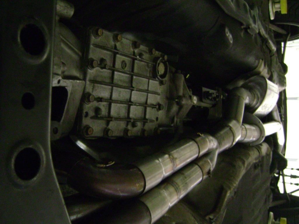
Also designed the exhaust itself to improve torque across the rpm range, but we have no testing numbers. I use 2 pipes instead of 1 and run through the 1st pipe only at low rpm and then both at higher rpm. Faster exhaust gas velocity should add power to an NA motor. Wouldn't do much that way for a turbo motor, but it would be cool to set up an exhaust like this where the 1st pipe was a normal large pipe you would use (say, 3 inch) and then use the cutout direct to air out under the passenger side door. More power and great sound when cutout is open.
1-14-2013
We weighed the stainless muffler box, including tips and entry piping, and its 23 pounds. However we need to measure the entire bumper with box against a stock bumper, because we removed a good deal of the frame and other materials inside the bumper. So, we are pretty sure the net gain is less than 23 pounds. The dual exhaust box would work for a turbo car with a single pipe back to the in-bumper box or adding a cutout pipe and letting the owner bypass all resonators and mufflers and essentially run without an exhaust when its appropriate... ![]()
1-17-2013
As to weakening bumper structure such that the hot muffler box gets jammed into the gas tank and it does a Ford Pinto... Nope. I'll ask Logan to chime in with anything, but the design of the gas tank, steel rear bulkhead, and aluminum bumper -- as Mazda designed it -- makes any contact between the hot stainless box and the gas tank nearly impossible, though there is always an impact potential that would smash through whatever Mazda designed or what we did..
Remember that there is a steel bulkhead running the full width of the car and attached to the extremely beefy rear frame rails. There is about 4 inches of free air in between this steel bulkhead and the gas tank. So, first just considering the impact that would be required for the rear bulkhead to deform and be pushed in contact the gas tank, the impact would have to be really significant. Second, the stainless steel box, which is bolted to the aluminum bumper frame, itself serves as a crush zone. It will do the accordion thing and be flattened up against the rear bulkhead, thus absorbing a lot of the force.
(I would also note that Greddy has been selling front mount IC's for a long time and it virtually eliminates the usefulness of the front bumper. While there's no gas tank to consider, engine bay fires can occur. That has never stopped anyone from doing an FMIC.)
Again, I am not saying there are not issues to be considered, but I think we have thought about most of them in some depth. We are going to do some serious testing of pure heat issues. We are never going to do a rear impact test. So, we'll just have to wait for my first rear end collision. ![]()
1-18-2013
I'll add a bit more and maybe Logan will chime in. Essentially, our design exactly maintains the backend structure, as Mazda's engineer's designed it with the sole mechanical exception being where the pipe goes into the bumper. The middle of the bumper frame is now very hot, so that, if it ever did break and break through the steel bulkhead at the back of the car, you might well have a problem. However, I think any such rear end collision would be of such a large magnitude that any stock-mounted exhaust would experience nearly the same problem. Any additional comments would be appreciated, since these kinds of things are so important and, even though we are trying to consider everything, we don't want to miss something. ![]()
2-1-2013
We're making progress on the build. Should have some pictures soon.
Bought a set of the same 18 inch Speedline Corse's that came on my 94 Porsche. Wheel Collision Center painted the centers and polished them. Looking for tires. I've only had 17 inch wheels on the car and want to see what difference 18's make.
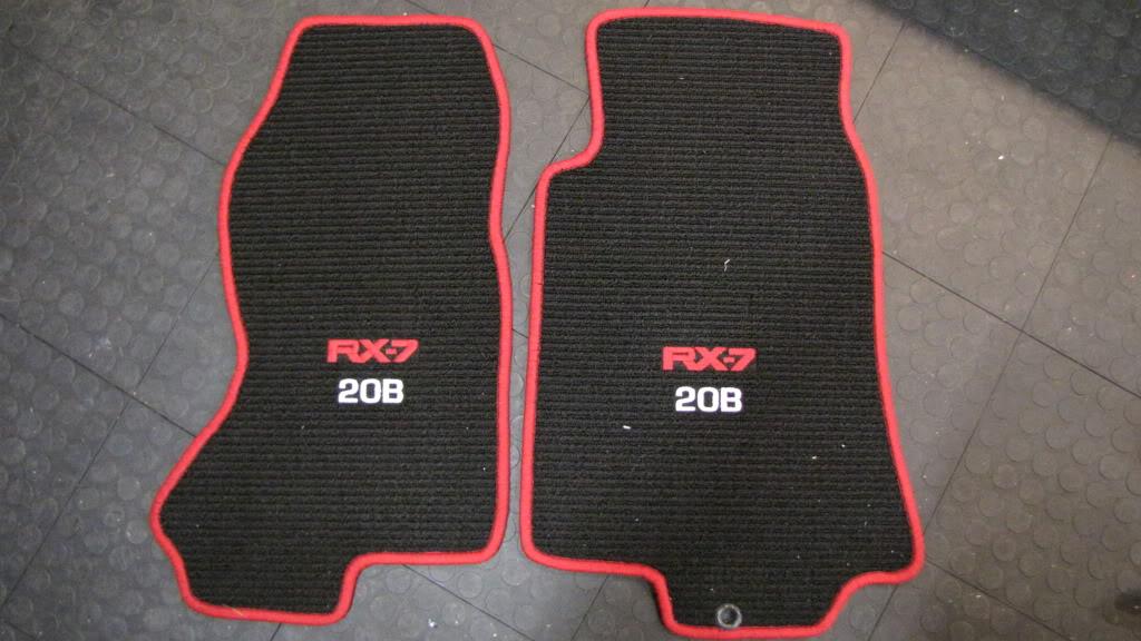
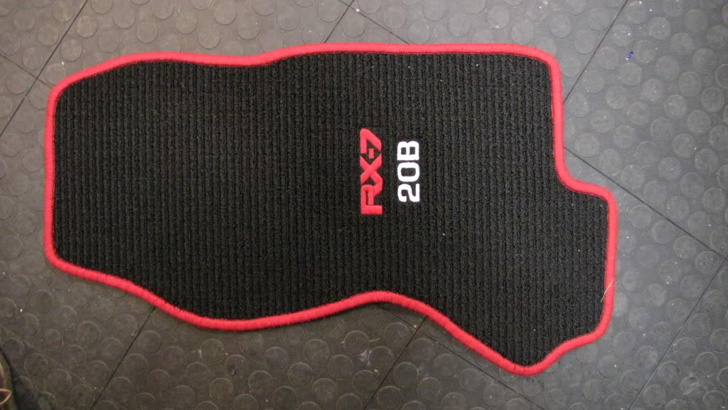
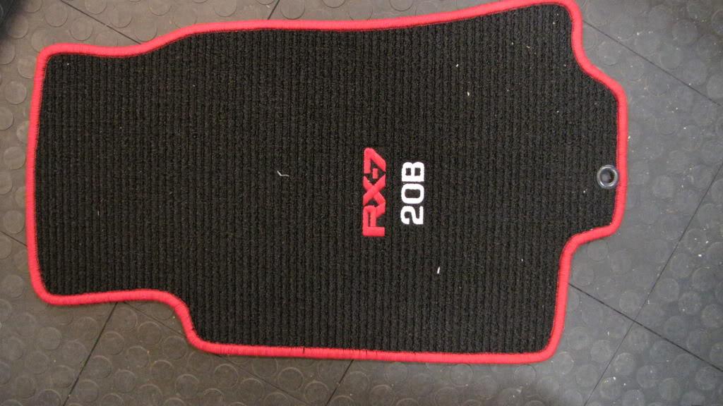
And JasonS made up some of his berber ("lux touring") over-mats for me and they're very nice. Nice product if you want mats.
2-2-2013
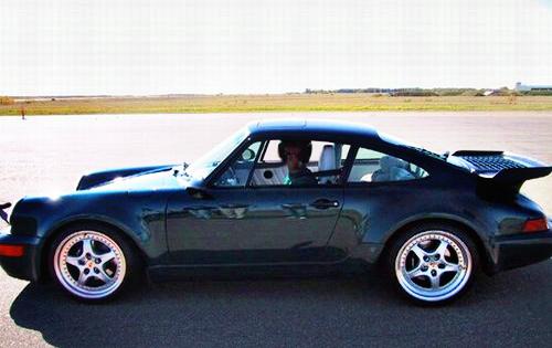
Thanks, Benny... They are Speedline Corse Alessios and mostly found on Porsches. I had a slightly different model on my 965 Turbo. Here are some pictured of the Alessios on 90's Porsches. So, they are sort of a contemporary 90's wheel that kind of reminds me of the Meister S03's.
Gordon
3-3-2013
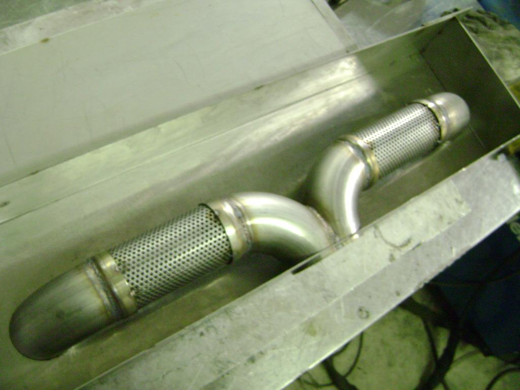
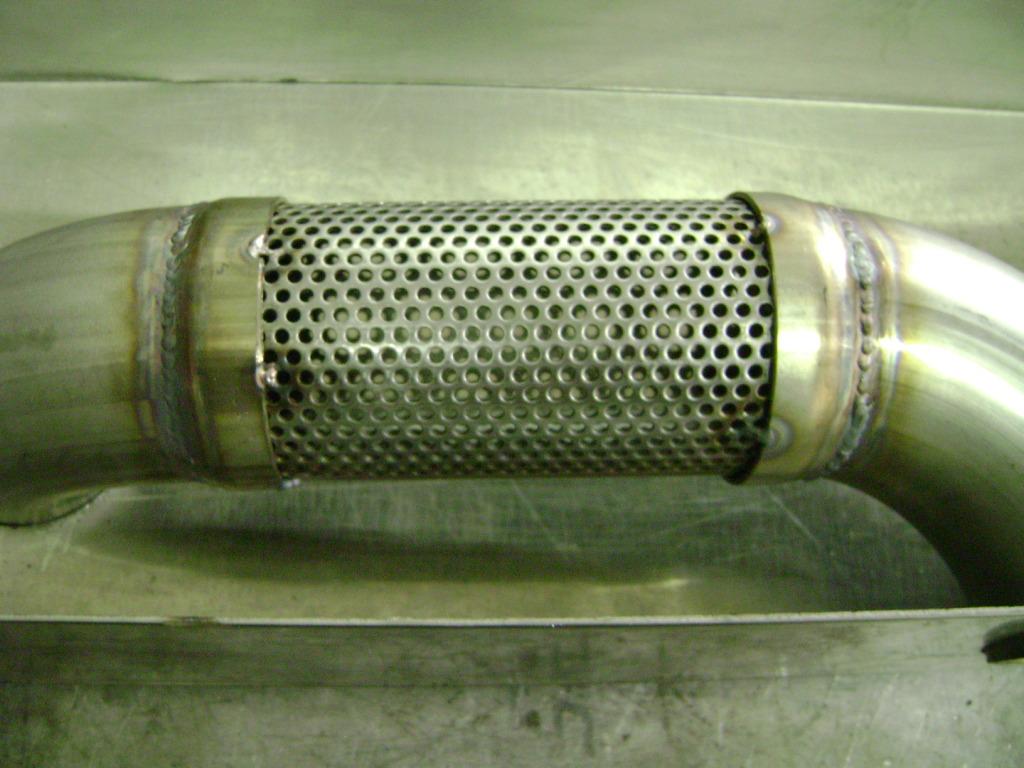
Here are the missing exhaust photos. The new photobucket still is screwed up a bit.
Gordon
Here are some more showing the insides of the exhaust box...
Gordon
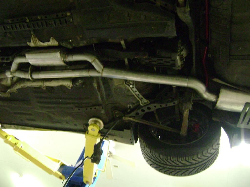
And, the back end...

3-8-2013
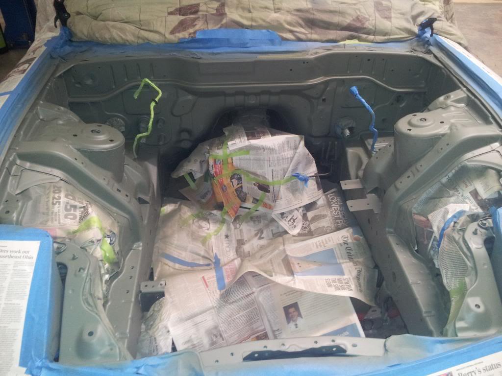
So, the engine bay is starting to come together. I've eliminated so many things over time, but still found a bunch of things I could get rid of or hide or change. Logan made a really nice black-anodized aluminum oil reservoir that fits the spot where the deleted ABS was. We sanded the engine bay a bit and sprayed the primer coat today. Should have the BB color coats on tomorrow and the clear on Sunday. I got a new set of fender liners (usual thanks to Ray Crowe ![]() ) to put in when we're done.
) to put in when we're done.
I'm spending some time getting **** about the nuts and bolts that hold everything together in the engine bay and on the engine itself.
Gordon
3-9-2013
Tim and David... Good. Any drawbacks?
REVLUC... Thanks, buit you have the car. ![]()
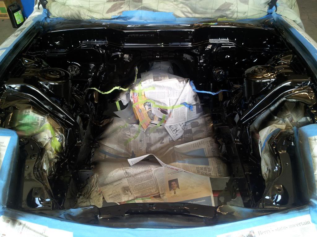
Here are a few pictures of the bay with 2 coats color. We filled a few of the holes that won't be used.
Gordon
3-18-2013
We're in the final stages on a bunch of things. The motor build. The new exhaust. Wheels and tires. So, Logan has me occupying myself with some of the last details.
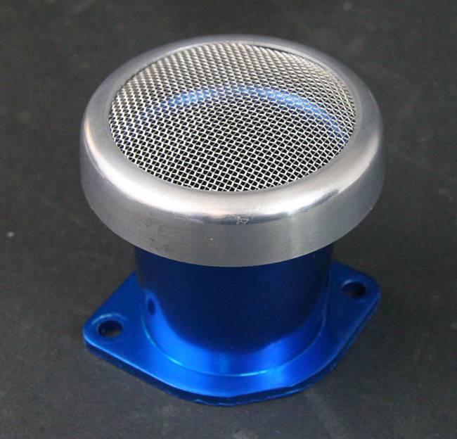
Don't want an air plenum to feed the throttle bodies. Don't need it. But I do need to cover the throttle body air horns (which I'm having re-anodized from blue to matte black) with some kind of filter. These are triple mesh screened filters and that should be fine.
Gordon
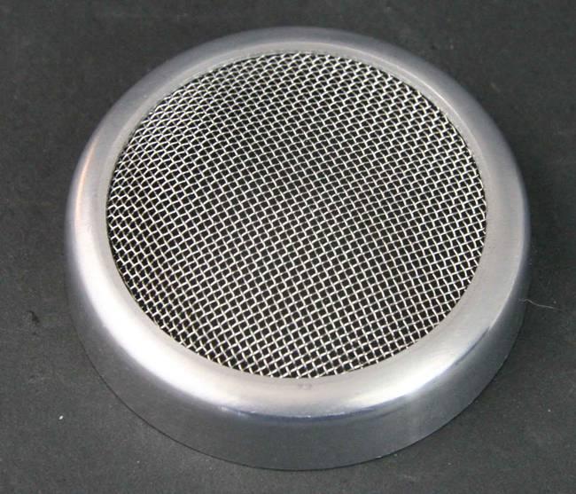
Should look like this, but with the air horns in black.
3-19-2013
No plenum... If my goal was horsepower, there would be a turbo in there. ![]()
I guess I should add that there are quite a few different kinds of filters out there, including some that are waterproof, and they are definitely helpful in keeping mice out of the intakes. If this doesn't work the way I would like it to, I can always add an air box, but I am trading a bit of power for no plenum and hard pipes.
I shouldn't have been so flip in my reply. There are a lot of filtering options with screens of different sizes and materials so that you can eliminate most particles from getting into the throttle body. I am going to use as little filtering as possible to be sure I am safe.
Plenums need flitering as well, but help make power by being slightly pressurized and therefore being able to feed the throttle body more air especially at high rpm. My car is not dry-sumped and so my rev limit is about 8800 rpm under normal driving conditions with a few bursts to 9,000 or just a bit more. I will probably lose a little power between, say, 7,000 and 8,800 rpm, which I hope to make up through better exhaust gas scavenging. Lenny's car will be dry-sumped and he should be able to run 9,500-10,000 rpm and can use all the air he can get up top and a plenum is the only way to go.
As I have said time and again during this cars life, I am trying to end up with a simple and reliable motor that makes good power and sounds great. Whenever I drive a new car, I am amazed at how bad they sound and how indistinguishable they are one from the other. You used to be able to tell that a Porsche was coming by the way the flat air cooled 6 sounded. Good luck with that today. So, why spend $50,000 on a stereo and only listen to Lawrence Welk playing a senior home? ![]() The sound of 3 throttle bodies sucking air is great and I want to hear it.
The sound of 3 throttle bodies sucking air is great and I want to hear it.
3-19-2013
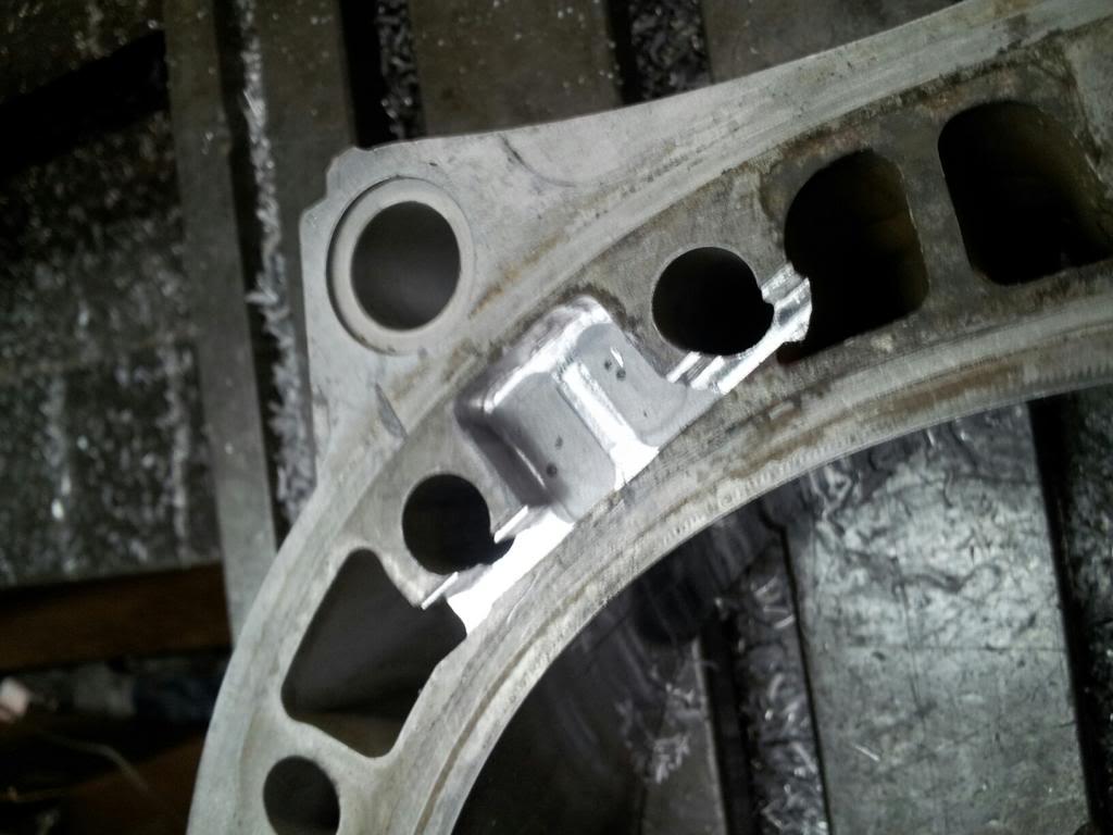
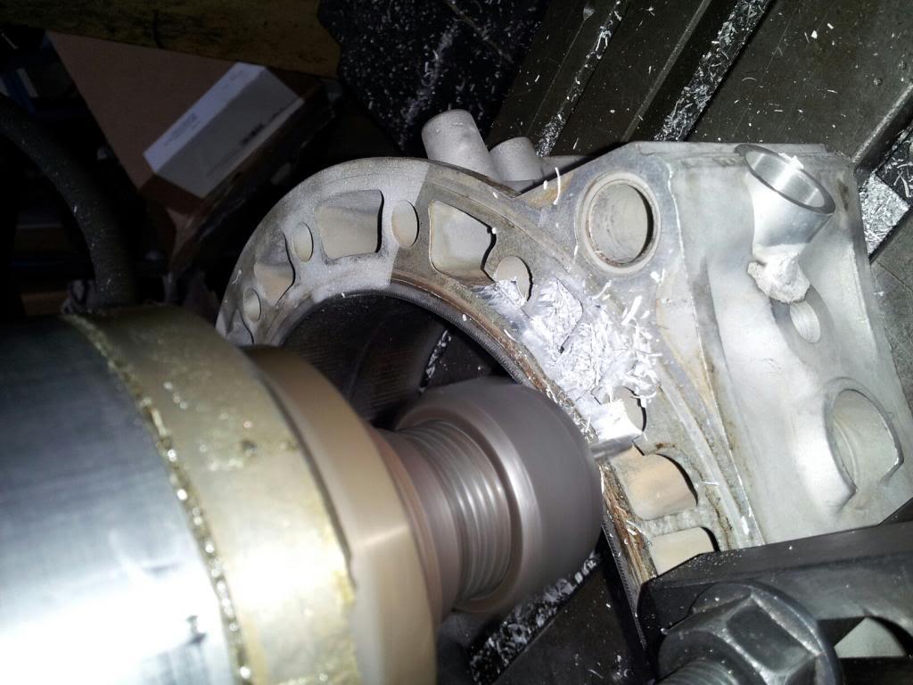
I've got the new Speedlines and Toyo Proxes R888's on and my off-roading lift kit... The 285 rears look nice. Also, here are a couple of pictures of the third plug bung being machined and inserted.
Gordon
Here is the only shot I got of the wheels and tires.
And here is a housing being machined for the third plug and with the plug bung inserted.
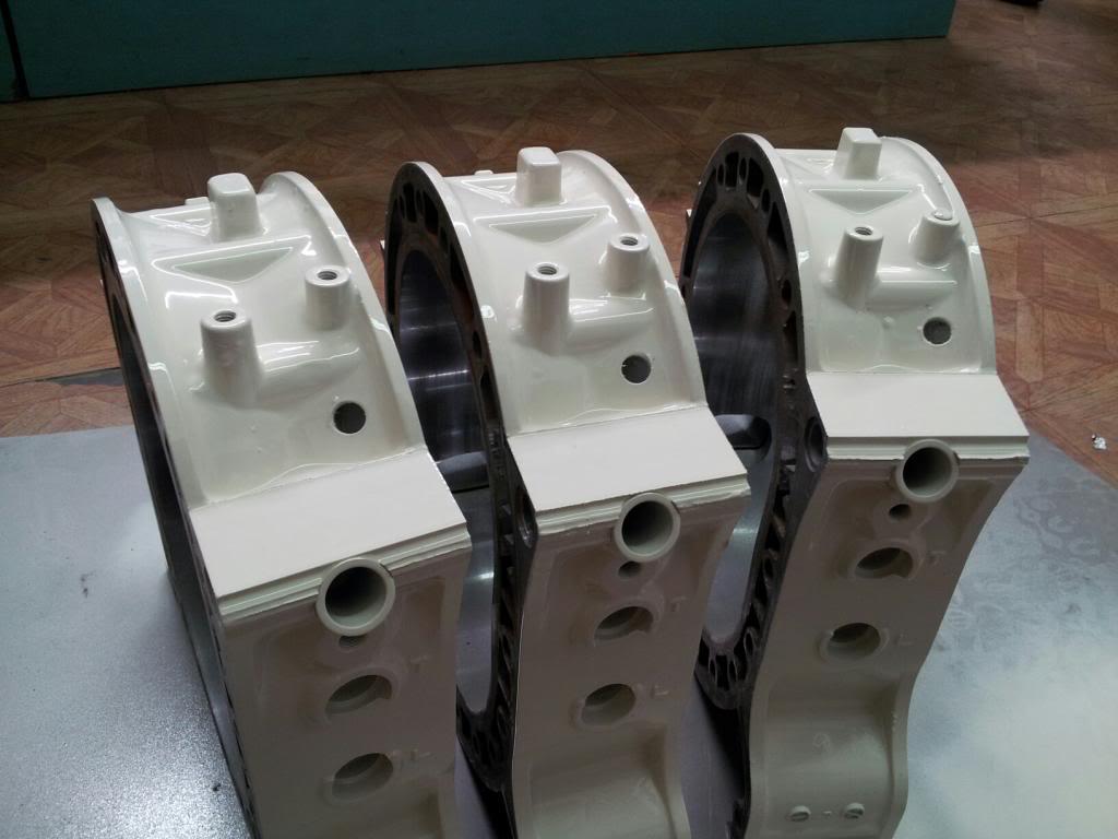
3-22-2013
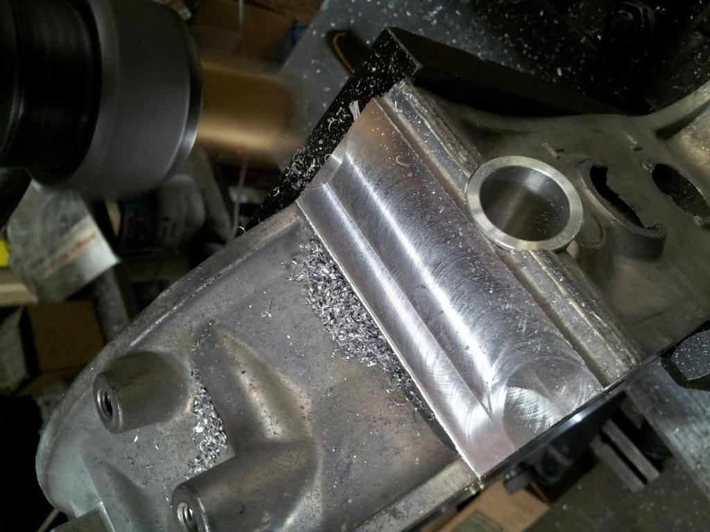
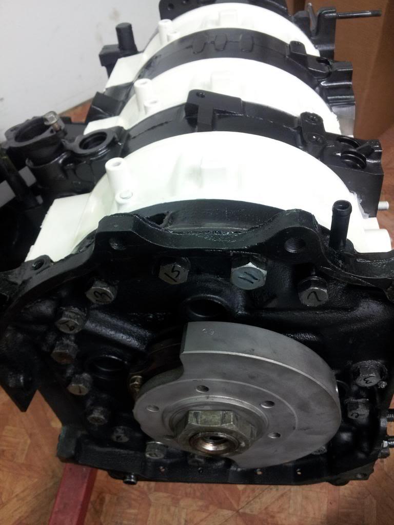
Here are the finished housings with the 3rd spark plug bung inserted above the trailing plugs at the top of the side and the housings have been machined for much larger cooling passages. There will be 3/8ths inch aluminum hard lines directly plumbed into the holes in the housings flowing coolant to enlarged passages inside the housings.
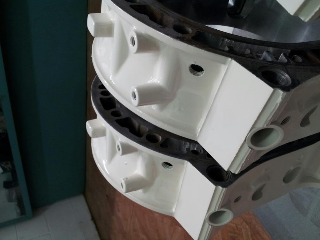
The drawing below shows the hard coolant lines going into the housings...
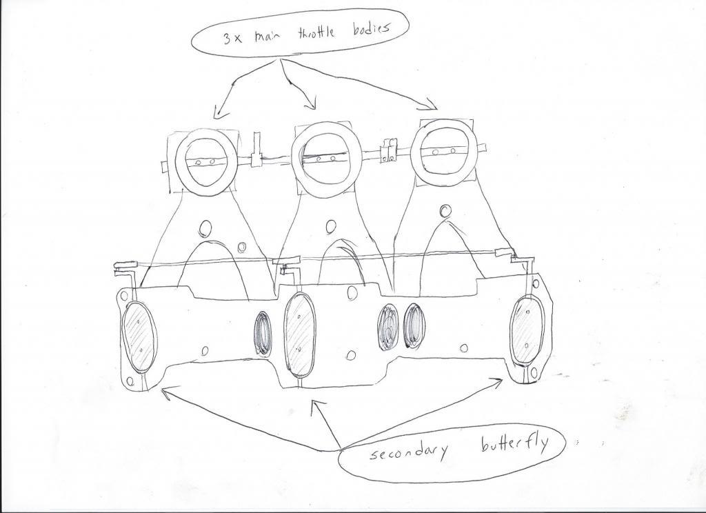
And, here is a drawing of the intake and induction side showing the ITB's and runners down to the intake ports and secondary butterflies in the secondary intakes. We got the idea from the way the Vette's LT5 motor has 2 butterflies and runners per cylinder. It will give us much better flow control and along with the 3rd spark plug, we should further improve gas mileage.
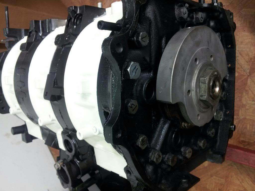
3-24-2013
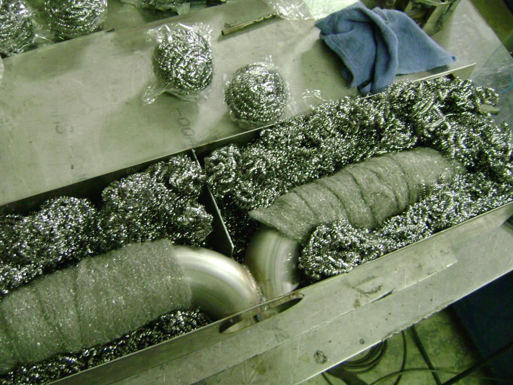
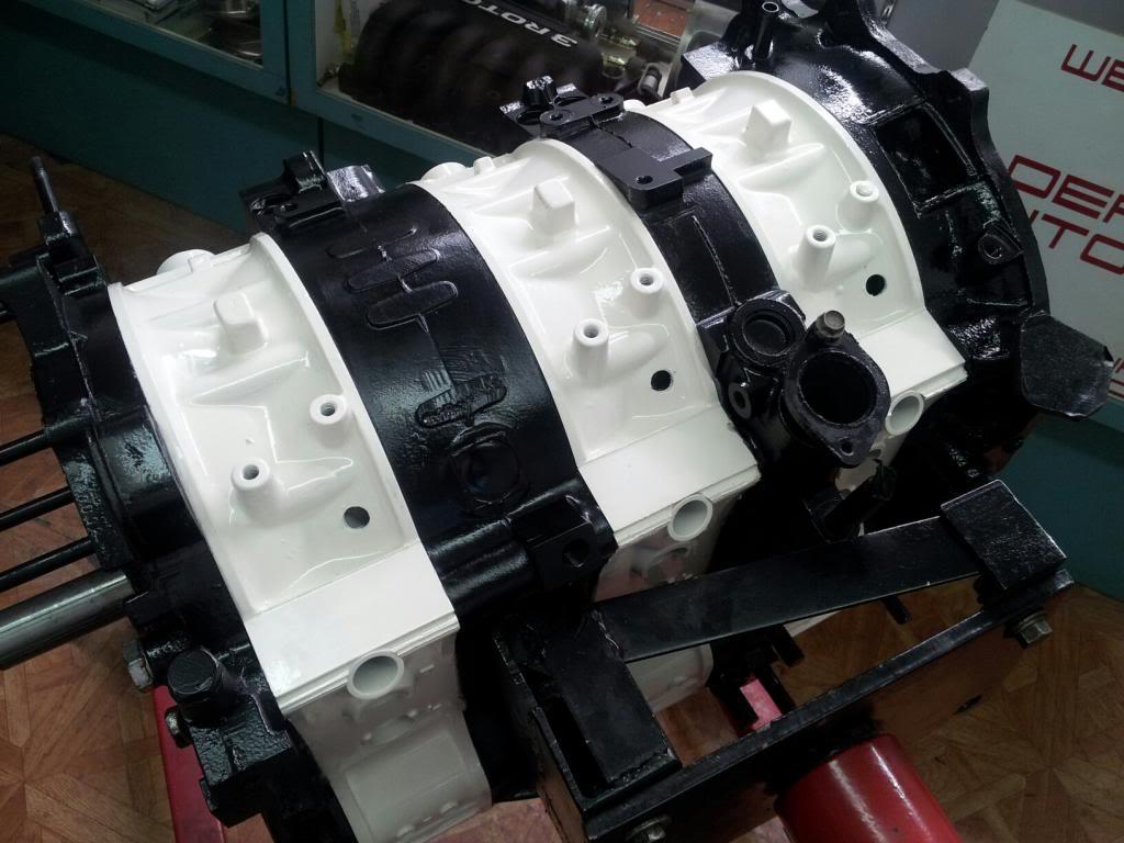
Here's the finished short block. Now, we need to get it in and build the intake and add the ITB's, finish wrapping the in-bumper muffler in DCI Extreme XT5000, and hook up the exhaust cutout, and finish the little stuff, like the oil reservoir, and tune. Another Deals Gap down to the wire build. Should be buttoned up by the 5th and putting some miles on it.
G
3-26-2013
Diabolical... No worries singing Logan's praises here. He's an artist and unlike any tuner I've worked with over the years. Most just sell you a 500 whp A-spec, slap WI on, and load the PFC map. I'm fairly knowledgeable and have ideas I want to try and Logan and I communicate well and he comes up with things or I do and he makes them reality. I think the engine will be done shortly and there's then little left for me to do. The transmission redo, some bracing and paint is about all. I think the final engine design and specs are really interesting not just in power, but hopefully in reliability, gas mileage, lower maintenance costs and ease of maintenance.
Nice job!
Posted by Diggymart on 3/13/19 @ 9:54:43 PM