You must be logged in to rate content!
13 minute(s) of a 548 minute read
6-15-2012
Decisions decisions. I had originally thought to make the windscreen in two sections, divided horizontally with the upper section hinged at the top. I have now decided that this is impractical and will use a single piece of glass instead. In doing this I can overcome a number of small problems and believe that it will be a far neater and more satisfactory outcome in the end.
6-17-2012
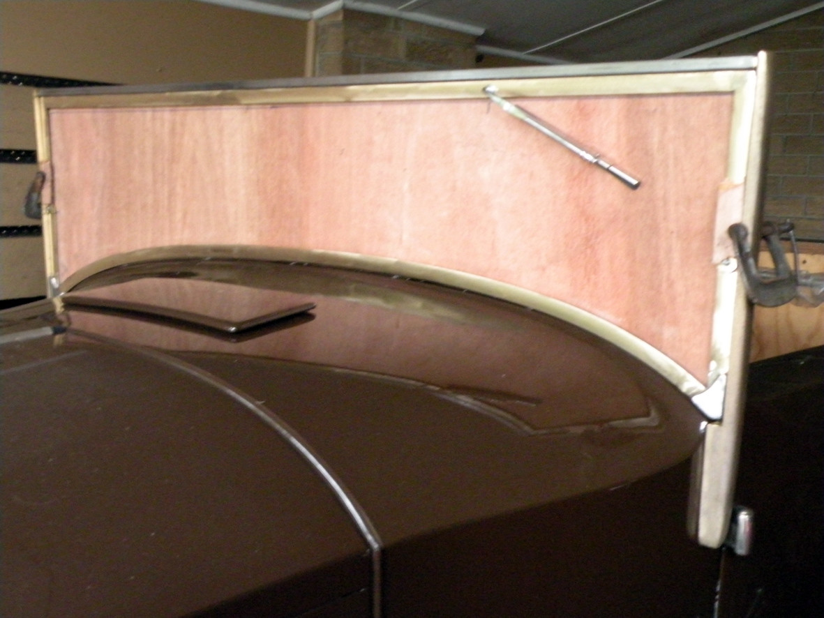
Another day and a little more progress on the windscreen. The one last job I have to do is to drill and tap the holes for the fixing screws that attach the top rail to the side pillars.
Before you all rush to your keyboards, the camera angle has thrown up some strange perspectives. The sides of the windscreen are actually perpendicular and parallel!
6-19-2012
Thank you to ALL my friends
I was not digging for compliments, I would just appreciate a little feedback occasionally. I am always conscious that not everything I do meets with instant approval. The change of plans for the windscreen for instance took quite some thinking about and time worrying whether it was the best solution to a difficult problem. I am always open to helpful suggestions and comments. As it is I have virtually made TWO windscreen frames and used up almost 12 metres of brass channel section.
6-20-2012
Today has been relatively low key. Since putting the gearbox back into the Lagonda Rapier I have wanted to do a reasonably long test drive. We have a VSCC Event this coming weekend and I needed to be sure that all was ok. This morning was cold but with some weak sunshine so I headed out through the nearby hills to visit Dave the Painter. I discovered that the adjustment for the remote control gearshift was failing to pick up top gear about every second or third change up. All it needed was one turn of a threaded rod, all that is left on the must do list is to buy and fit two new windscreen wiper blades. That left this afternoon free so I pulled out the bits of the basic top frame that I had started on months ago. Naturally with Melbourne's climate it had a complete coating of surface rust. After three hours with an aggressive wire brush in my angle grinder, a couple of sheets of sand paper and a spray can of Black "KIL-RUST" the bits have been "hung out to dry". At the very least they will not go rusty again.
6-21-2012
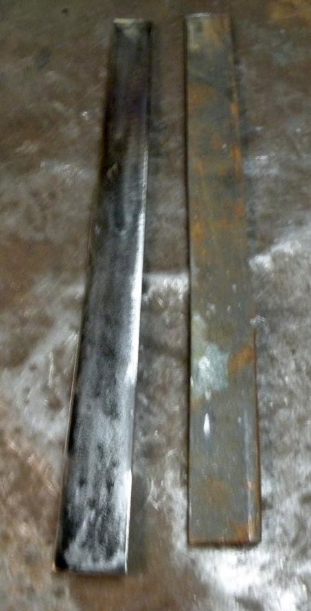
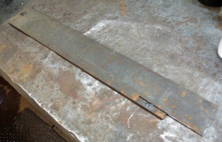
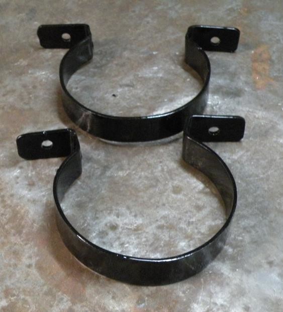
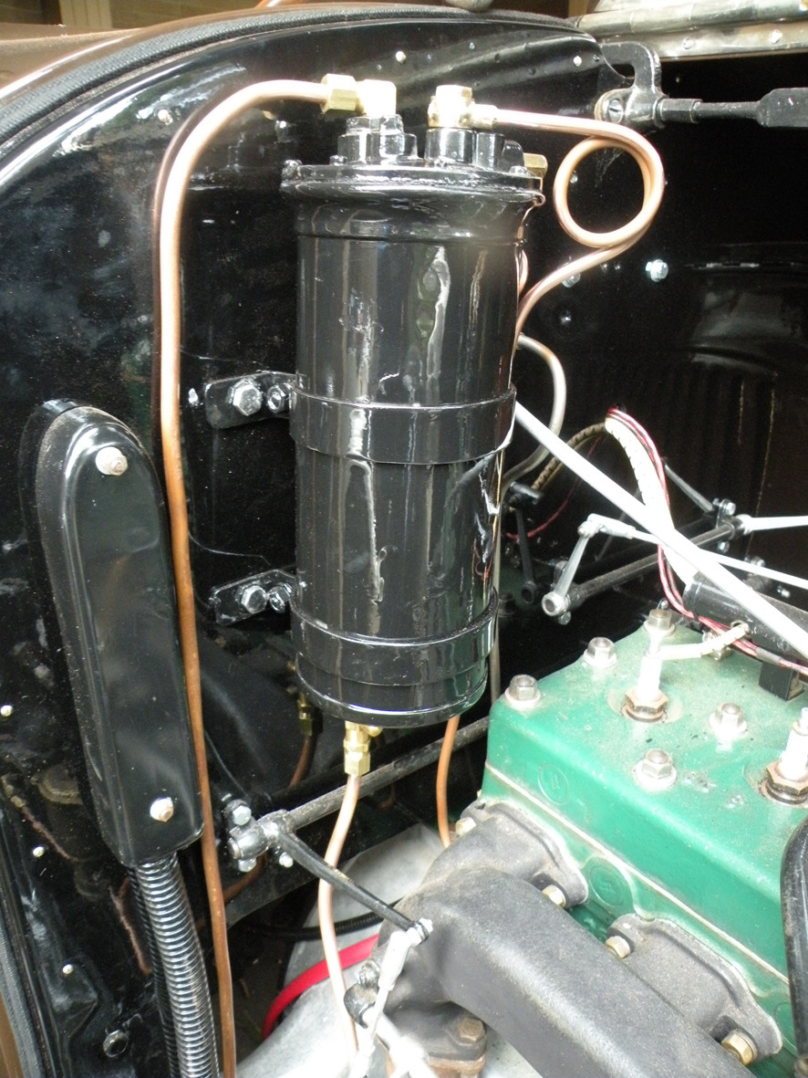
Yesterday I decided that I had procrastinated far too long and that my next task was to make the mounting straps for the vacuum tank. The photographs tell the story. Starting with a length of 1 1/2 inch X 1/8 inch strip the first job was to slice this into two pieces 3/4 inch wide. This was done using one of my favourite thin cut off blades in my angle grinder. These were then de-rusted and de-scaled and the edges cleaned up using a 120 grit "flap-wheel" on the same trusty angle grinder. They could then be measured and marked up having first measured the circumference of the Vac tank. The ends were then folded in my off-set vice and the necessary holes drilled, finally they were rolled around a former of the same circumference as the tank (in this instance a worn out emery wheel from the bench grinder). Finally they were given a light sanding to clean off any hand prints etc and given a coat of fast drying etch primer. This was again given a light sand-papering and a coat of black paint then hung up to dry. This morning they are ready to be fitted to the Vacuum tank. Next task will be to fit it to the bulkhead then I can finally move on to completing the plumbing of the petrol and vacuum lines.
6-25-2012
Help!
I know that the improvements to the set up are obviously brilliant but I really am having trouble coming to terms with the system for uploading photographs. Can someone please explain or I will just have to give up, the frustration is killing me. Added to this I just don't have the time to keep going around in ever decreasing circles.
6-27-2012
Thank you Matthew
I have successfully posted some photographs on my other (Lagonda Rapier) thread. Work is continuing on the Packard. Today has been spent sorting out all the little brass pipe fittings to connect up the Vacuum tank. I still seem to be missing one hopefully tomorrow will solve that problem.
More progress on the fuel system I have discovered a local firm Pirtek who carry a large range of brass fittings for imperial size (1/4 & 5/16 inch) copper pipes. So at last I can move on one step closer to having the Packard running.
6-28-2012
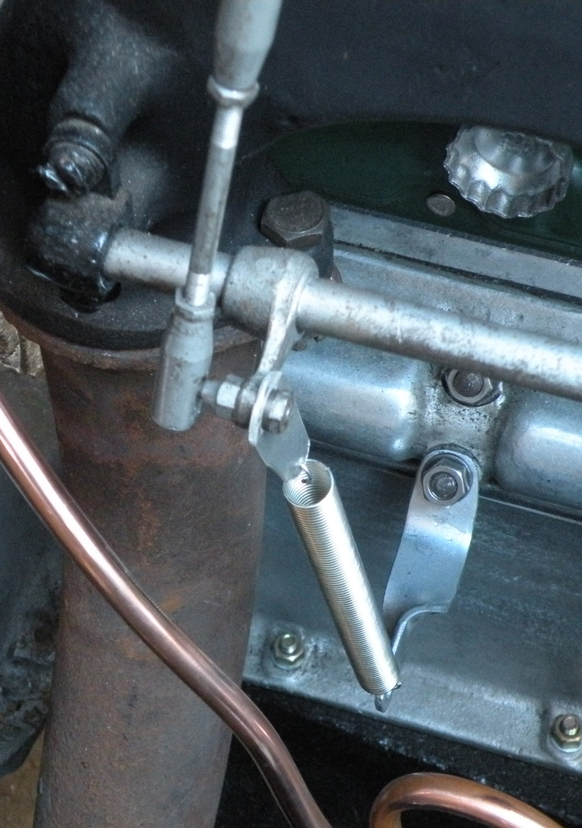
At last. The next question is where does the return spring for the throttle linkage go?
6-30-2012
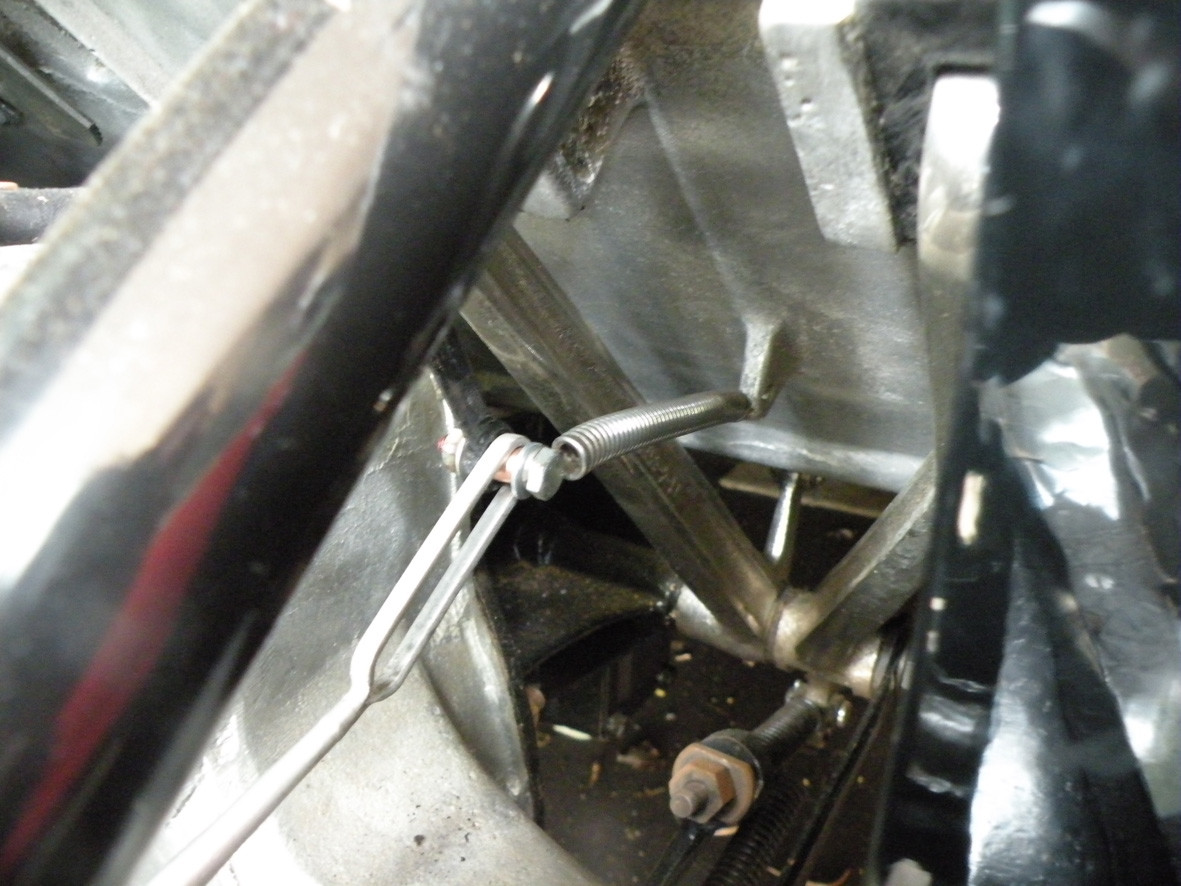
At last after some hour or so of standing on my head, I have the throttle return spring attached. To meet with modern safety requirements I will probably have to fit a second spring somewhat closer to the carburettor.
7-1-2012
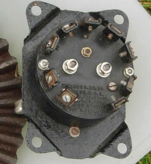
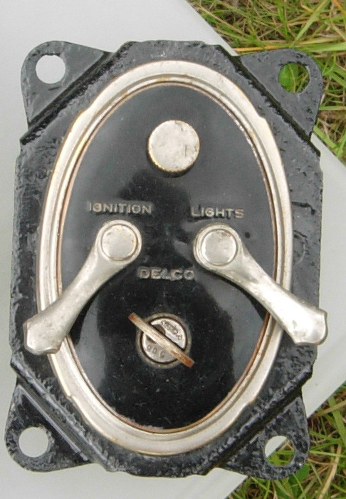
My UK based friend Anthony Bryant who looks at this thread from time to time has sent me these photographs of the Packard ignition & lighting switch from an early series car. If anyone is interested in buying it I can put them in touch with Anthony
7-2-2012
As stated on 1162 I have now fitted the second throttle return spring as required under the Confederation of Australian Motor Sport (CAMS) requirements. This is required to have a direct action on to the throttle butterfly shaft. Not that I intend to be racing the Packard but I still think that a second return spring is a good investment in safety.
7-5-2012
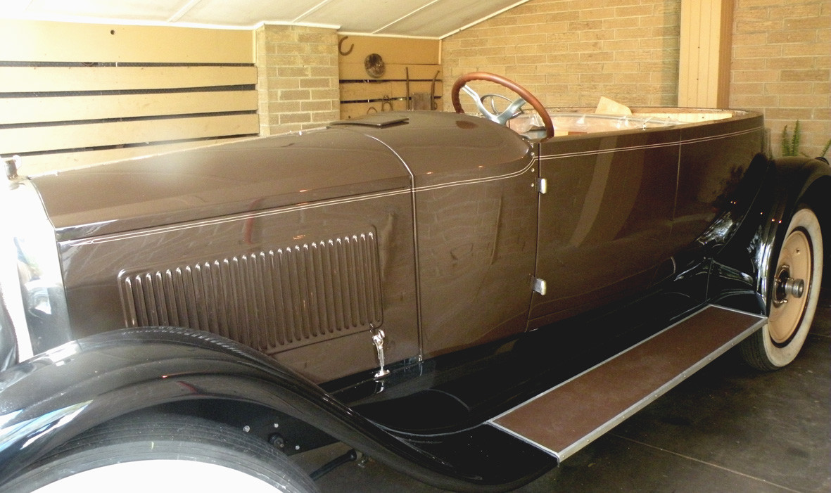
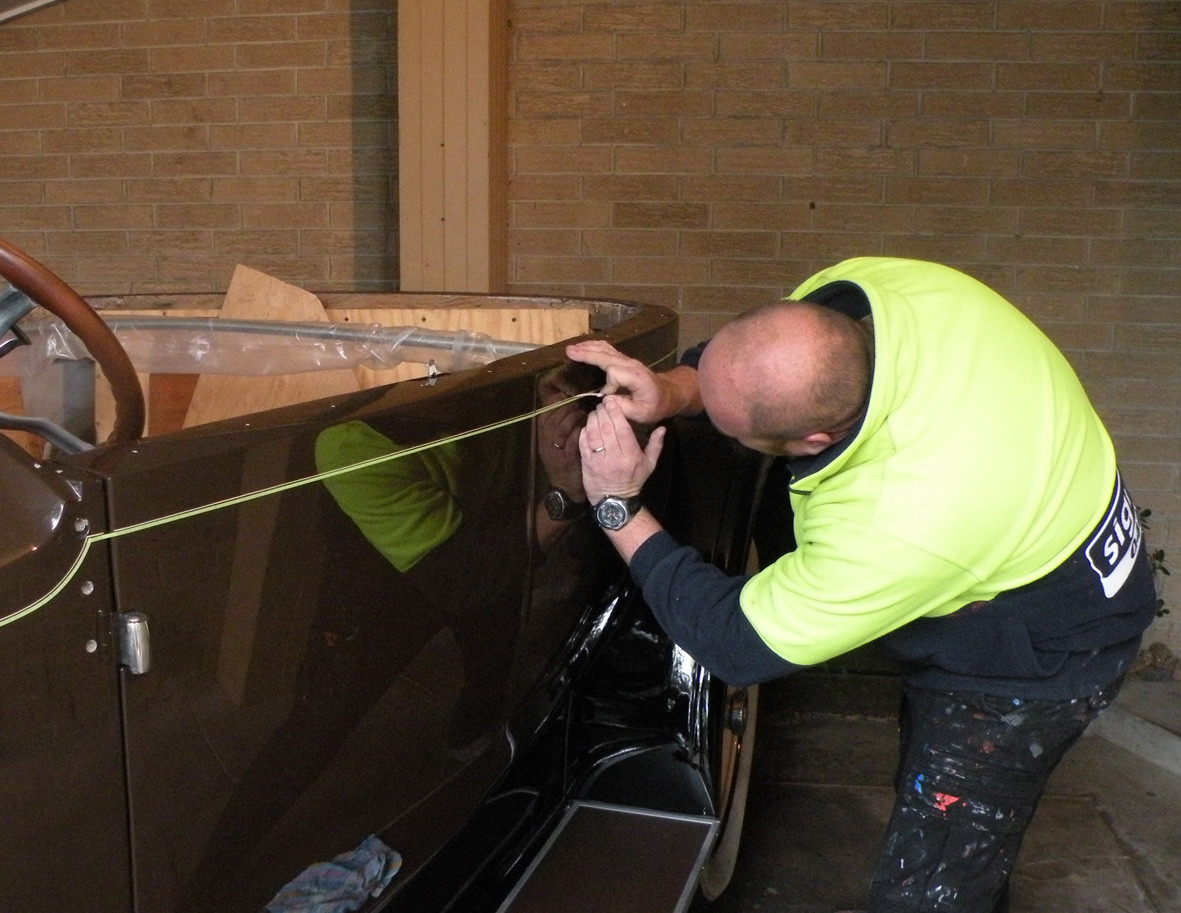
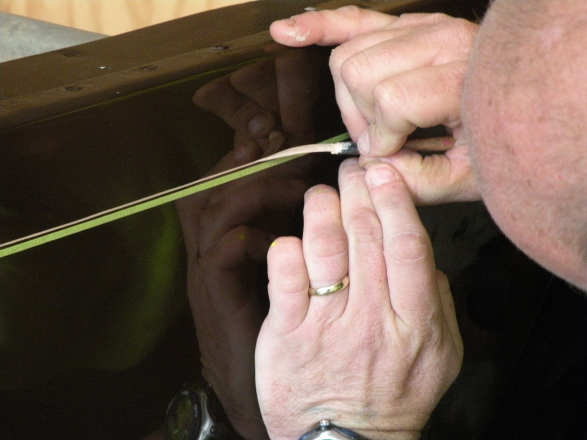
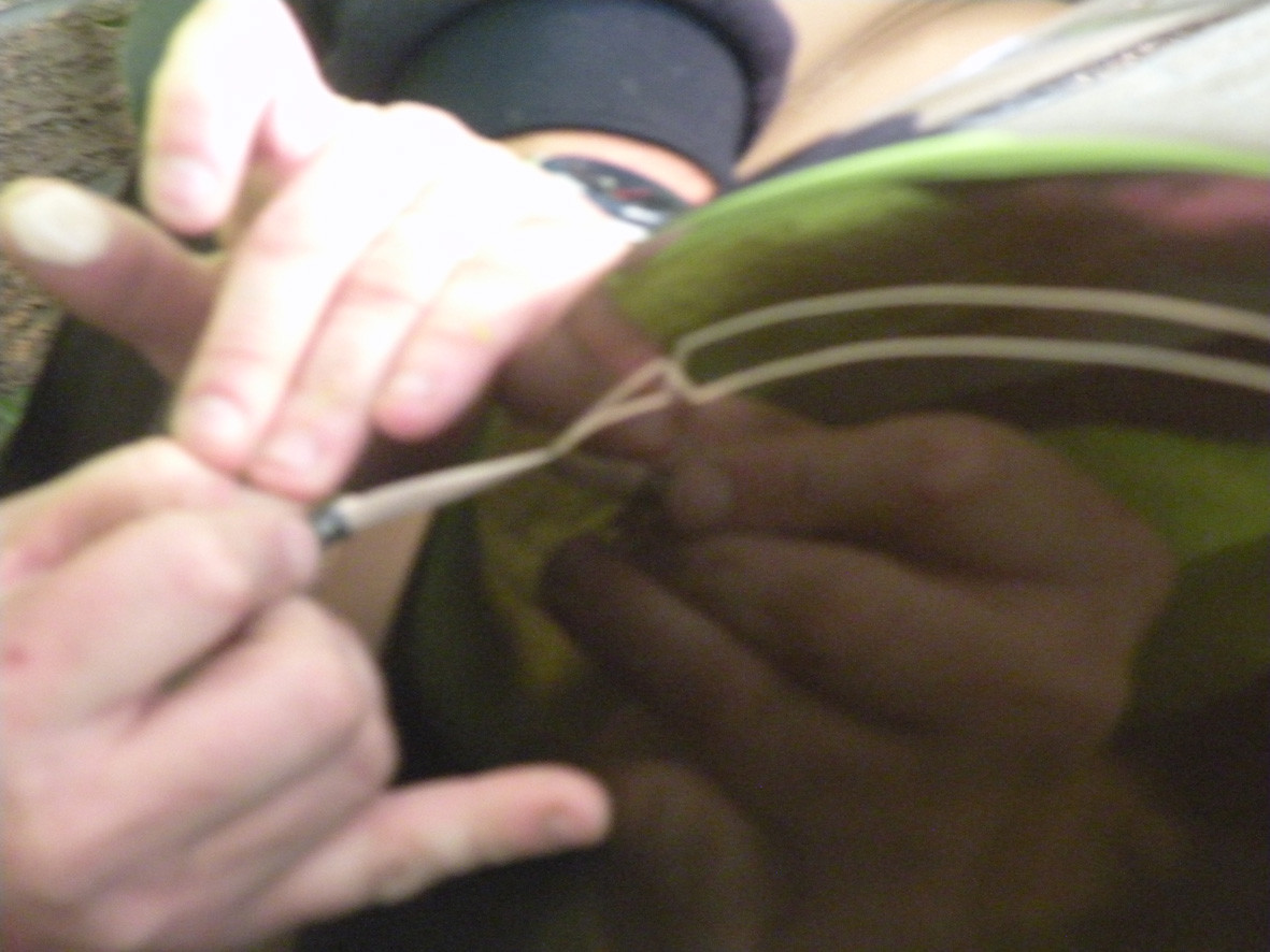
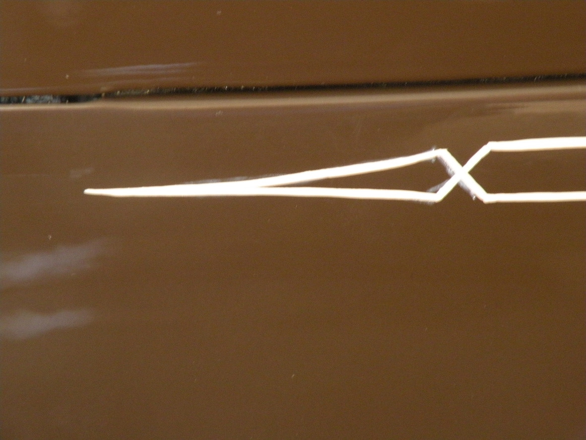
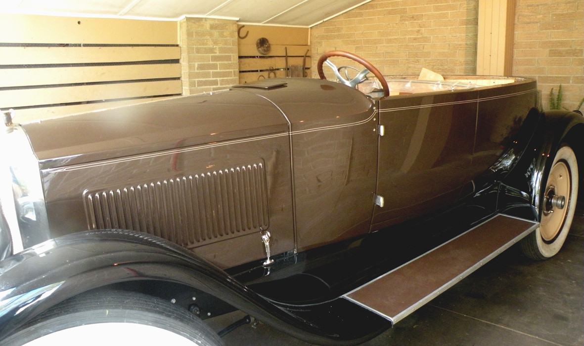
Another day and a little more progress. My friendly pin-striper Simon has spent four hours applying his skill to the Packard. I will let you judge the results for yourselves. Personally I am delighted with his efforts.
Hi All
I am delighted with the job that Simon has done with the pin striping. Re: the offending throttle linkage, I started to fabricate the correct clevis pin linkage yesterday afternoon. Next big job is to finish the windscreen and have the frame plated.. Then the interior trim.
7-6-2012
Hi Ian
Look forward to seeing your car after Dave has waved his magic wand over it.
Pete
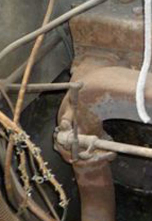
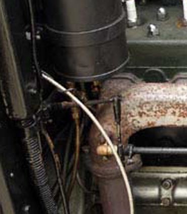
Before rushing too far into making the new (Clevis end) throttle linkage I thought that I should have a look at some archived photographs. One that an old friend in the US sent to me some time ago and the other taken when I first acquired the Packard as a basket case... Possibly the only thing wrong is that I had painted my linkages silver instead of black.
7-13-2012
Little by little progress is happening! Spend an extremely interesting day out at our son Steve's, he has been extremely helpful finishing off a couple of small but essential machining jobs on the windscreen fittings. Next task should be to take a load of "stuff" over to the platers for a nice fresh coat of nickel. That done I will be able to move on to ordering the glass.
7-15-2012
I am sorry that I don't have lots of exciting photographs to show you just now but as mentioned above this afternoon has been spent sorting out all those fiddly little bits to take to be nickel plated, First there are the two halves of the windscreen frame, the two windscreen side pillars, the rail that goes across the top of the windscreen between the pillars, two 1/4 unc X 3/4 inch raised head slotted screws, two 10 gauge metal thread round head slotted screws, the bits that go to make up the latches for the headlamp rims and the two 5/16 UNF special nuts that go with them and finally the two little angle fittings that go to hold the front rail of the top to the top of the windscreen. With the exception of the two windscreen frame and the pillars that I had cast in bronze from wooden patterns I made and the two special nuts for the headlamp rim latches I have fabricated everything largely from materials sourced from my "useful" bin. For the windscreen frame I actually bought a length (6 metres) of the correct brass channel section. This I cut up into no less than eight pieces then silver soldered it all back together again.
Recycling taken to the "enth" degree.
Bernie J.
For "useful" read; short lengths of steel, brass & aluminium, strip, rod, tube & etc, etc, all too good to be thrown away because I may find a use for it one day!
7-16-2012
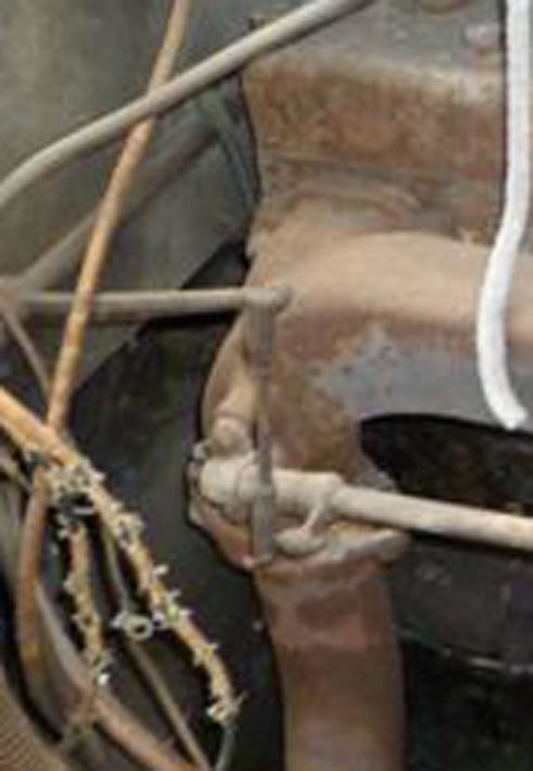
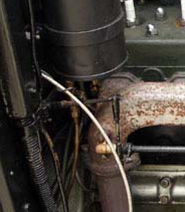
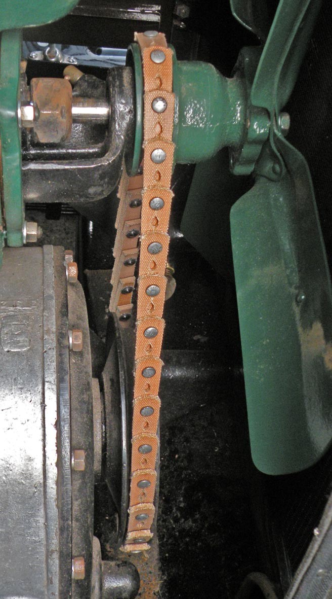
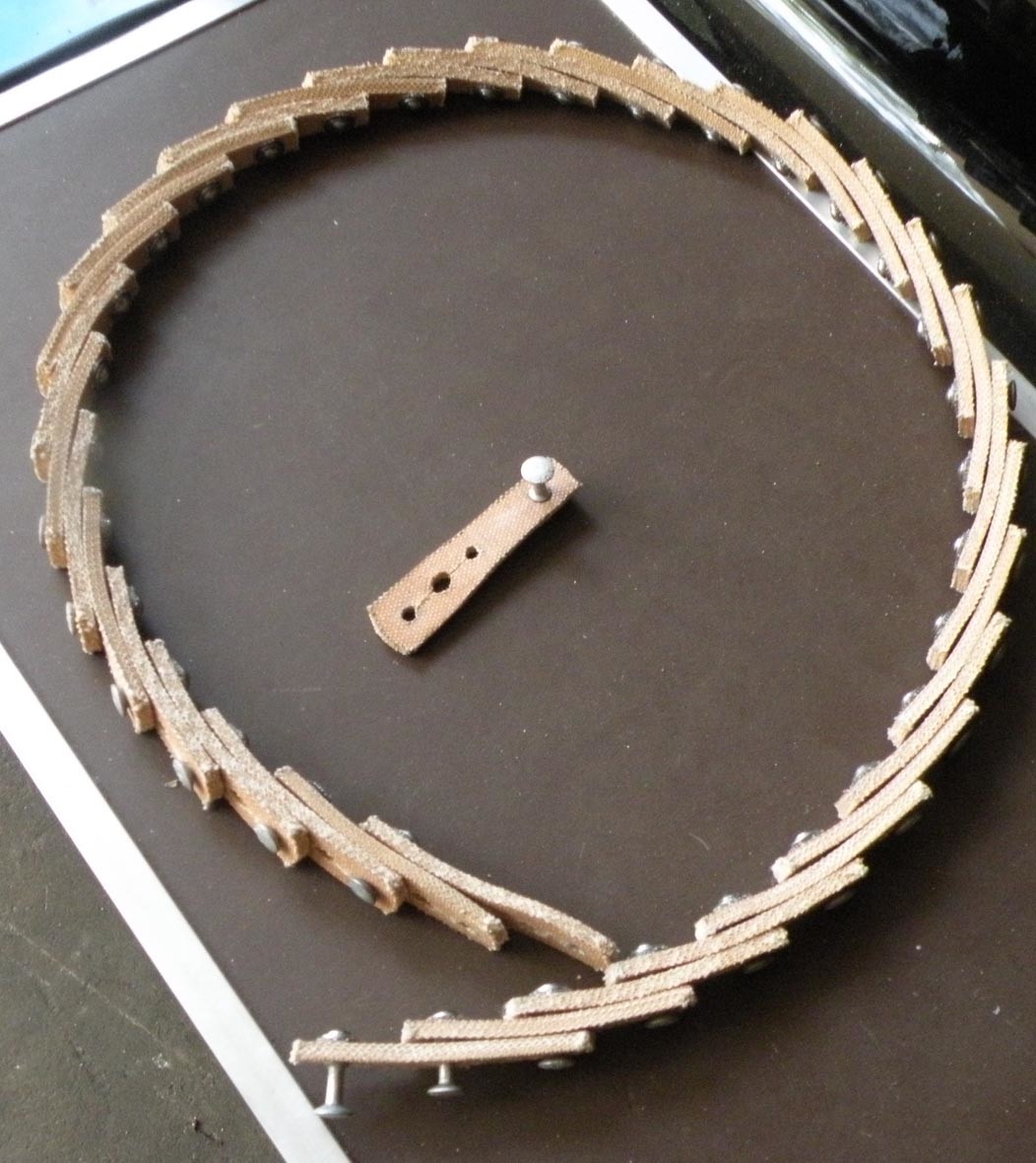
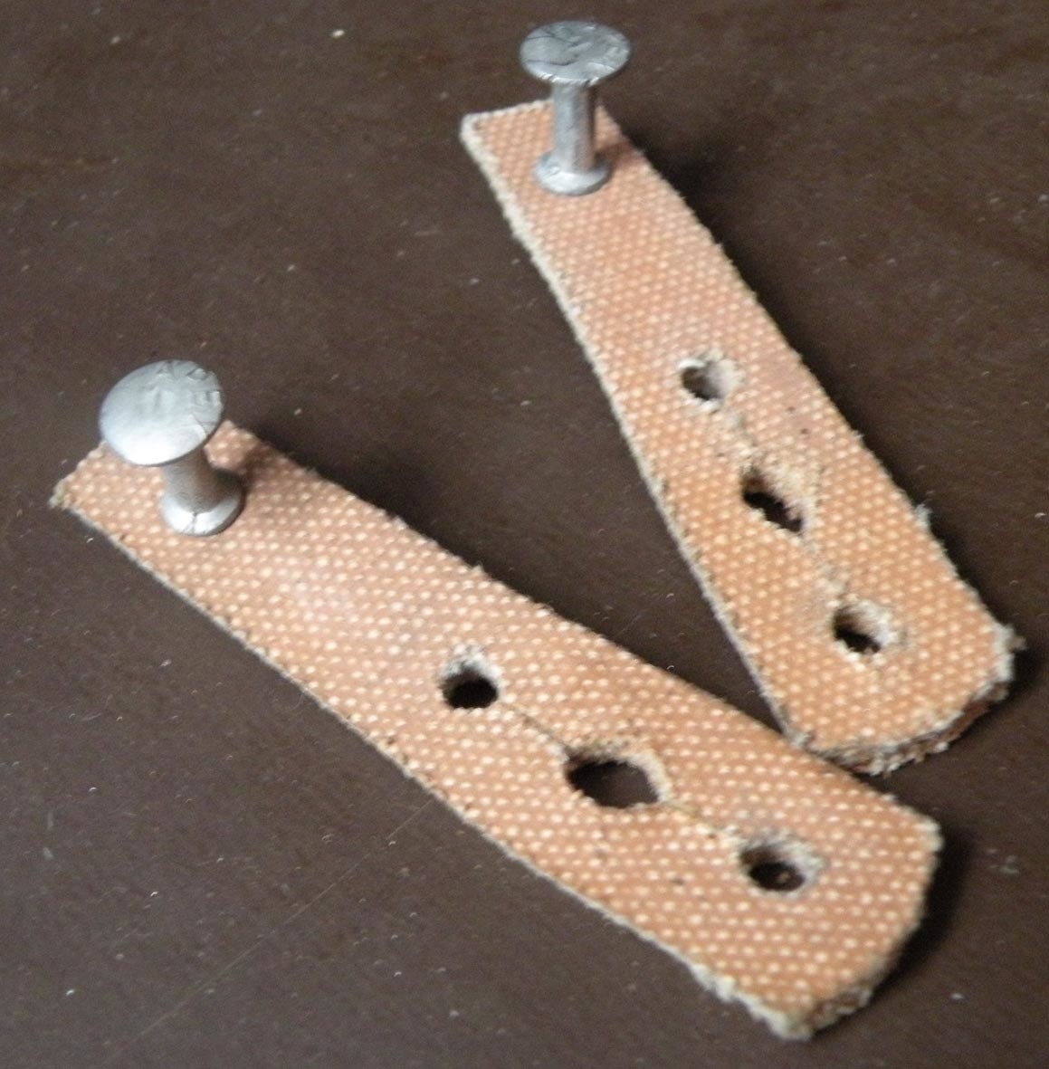
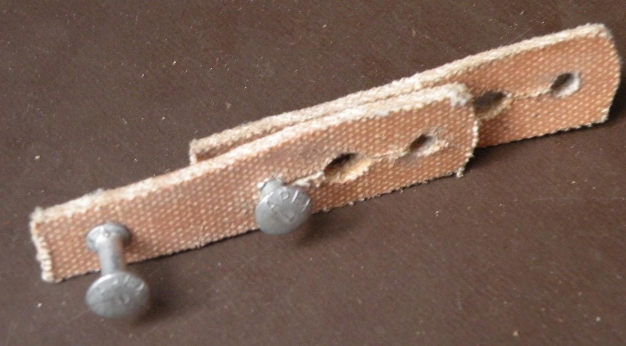
Back to work! Having delivered all the windscreen bits to be plated I decided that while I was out and about that I should continue on and pick up a length of "link" belting for the water pump/fan drive belt. Having given this much thought I had decided to use this type of belt as the clearance between the fan blades and the radiator core was just too close for comfort if I was to fit a conventional "B" section endless V belt.
Having made this decision I am sure that there will be at least six or eight experts who will tell me that 1. This type of drive belt is totally incorrect for a 1923 Packard and 2. that If I insist using this belt that I should at least put it on the right way around. That these belts are directional and that mine is on the wrong way around!
Hello Roger.
I am amazed at your ready confession to such ignorance.
There are two types of "link" belt that have been commonly used in industry for over a century. The Whittle belt invented by the grandfather of the English inventor of the modern Jet engine. This originally used wooden (lignum vitae) links. And the Brammer belt invented by a gentleman of that name living in Belgium. The Brammer belt is still used in industry, hence its ready availability over the counter from most Industrial Drive Belt suppliers. Some of the important features of this type of belt are its vibration free operation, its ease of adjustment to any given length, the ability to install it without the need to dismantle the machinery and the positive drive without the need for increased tension thus reducing the load on bearings etc. Modern "Toothed' belts such as cam drive belts are an adaption of the Brammer principals. This type of belt was also commonly used during the early to mid teens as the drive for "Belt driven" motorcycles and cycle-cars. Despite the attitude of many so called ANTIQUE car enthusiasts there WAS a sophisticated and thriving motor industry prior to 1950.
Google tells us:-
Commonly known as "Brammer" this type of V-belt (it cannot be used on flat-belt drives) is widely used in industrial and marine applications. Although more expensive than ordinary V belts it does have some important advantages:* It can be installed without having to dismantle the drive system and spend hours pulling apart well set-up or bedded-in components.
* It helps to prevent a drive system reaching a resonance frequency and is recommended where the transmission of vibration from the motor or other sources is undesirable - in precision grinding machines and high-speed lathe spindles, for example.
* It is of very high quality and claimed by the makers to have an improved shock-loading capacity and better abrasion, oil, chemical, damp and heat resistance in comparison with an ordinary V belt.
* It fits all standard pulleys - there is no need to replace or modify the existing setup.
* Adjustments to tension can be made without having to move pulley apart or together.
bravo!
Posted by CCmyVW on 1/26/20 @ 5:30:36 PM