You must be logged in to rate content!
4 minute(s) of a 173 minute read
10-30-2017
It has been said that we should "never look back" . Despite this stern warning I have just been doing that.
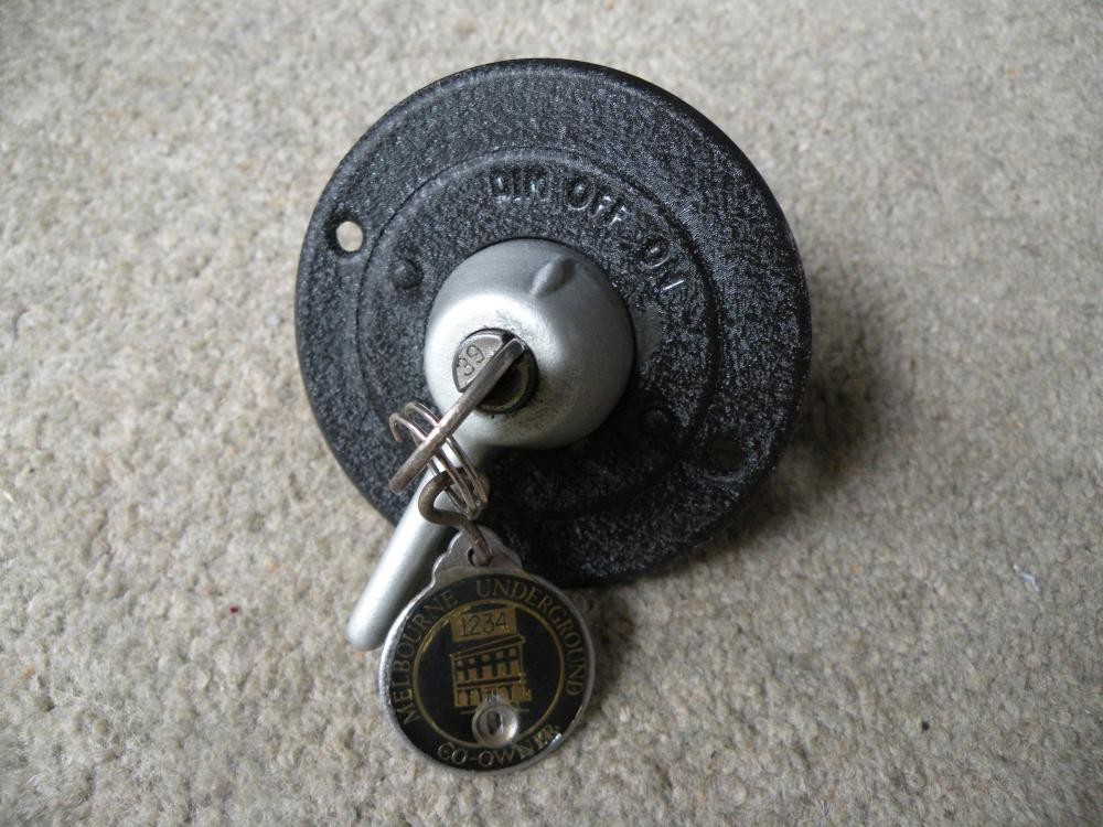
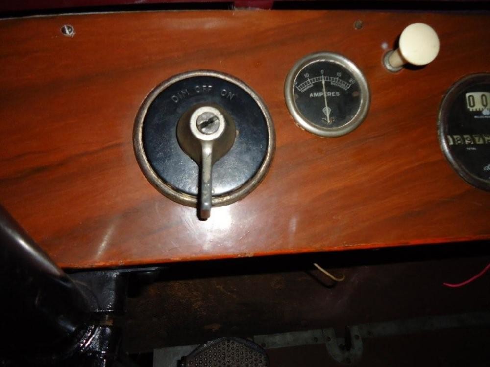
In Stude Light' s post #209 he included the attached photograph. I am not sure why it did not grab my attention at the time but on looking again I saw that the ignition switch was virtually the same as the one in my 1920 Light Six made by Briggs and Stratton specifically for connection to Magneto ignition. Perhaps Scott can confirm that the car with this switch is 1/. 1920 and 2/. If it also has magneto ignition? I also have noticed tha it has the same steering column support as my 1920 car.
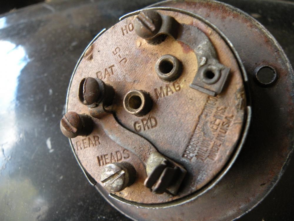
Also attached is this morning's photo pof the rear of my ign switch clearly showing (without their grubb screws) the two terminals linked to the Key switch. marked "Mag" and "Grd" the latter being an abbreviation for ground (earth) It is also interesting to note that while the front of the switch is marked "Dim Off and On" the terminals on the reverse side read "Head and Read". I really need to look again at the internals of the switch to see exactly how the current is routed through the switch. This is the only other photograph of a dash containing this particular B&S switch that I have seen. The final terminal partially obscured if for the Horn. Unfortunately this has the lugs to hold one end of the fuse missing but in the past had had a short piece of fuse wire linking it.


Hello Scott
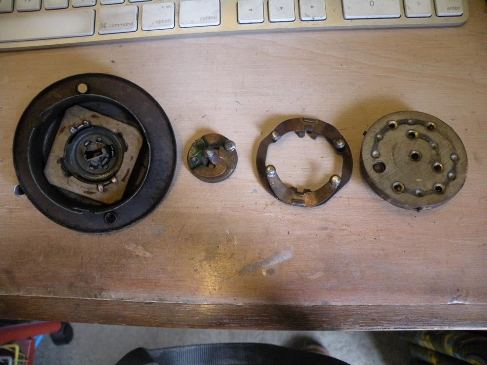
I can follow what you are saying completely and I do not doubt your word for one minute but , I have had my switch totally dismantled and cannot see anything that remotely looks like a resistor. The switch is quite simple in construction. For the purpose of this photograph I have not removed the actual key actuated lock mechanism.
The smaller(central) of the two rotating connectors is activated by the key and is solely related to linking the Magneto and Grd (Earth) in the off position.
The main body of the switch is designed so that it can only be assembled in the one way. There are three pins that engage with cut out locations in the body of the switch, these are placed at three unequal spaces.
The "Light"switch has three positions labeled Dim, Off and ON.
In the "Dim" position the current is taken from the "Horn" terminal which is connected to the Positive (Battery) through the fuse, only to the "Rear" terminal and the "Head" terminal is isolated . In the "On" position the current is taken from a Second terminal also linked to the Horn through the fuse connecting both the Head and the Rear. When in the "Off" position both the "live" terminals are isolated. I hope that you can follow this explanation.
With-out the dismantled switch on the bench in front of you it is difficult to visualise. BUT it is evident that in the Dim position only the horn and rear light have current going to them. The way the switch is asembled it can only be put together in the one way. The the ignition "Key" operated segment is at all times isolated from the live current. It is apparent that for a car fitted with Coil Ignition it would only require the centre section to be changed in order to link the Battery to the coil when switched on.
