You must be logged in to rate content!
26 minute read
DIY Coilover Install Thread (with Pics!)
Compliments of Scottslaw @ www.6speedonline.com
Hi Fellas: After much deliberation I decided to tackle the install of my fvd pss9's on my own. I searched basically every coilover install thread I could find and amassed as much info as I could before starting, and had a hard time finding a really detailed start-to-finish DIY, so I decided to do my own. So here it is:
Preliminary Work:
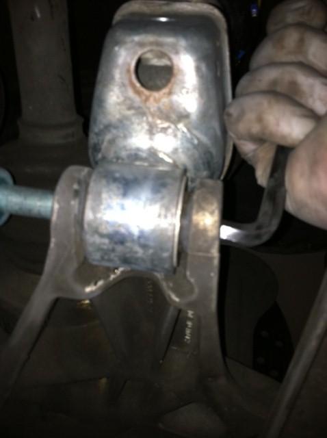
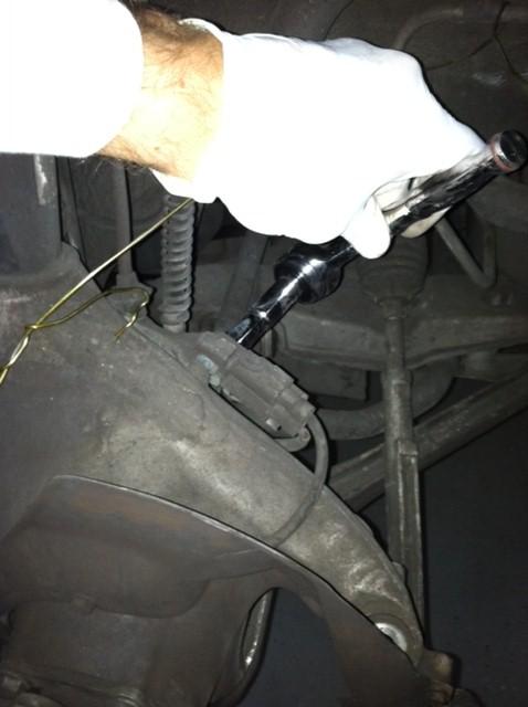
1. Night before: remove center caps for the front wheels and shoot them with penetrating oil (I use a product called PB Blaster, which works great). The 32 mm nuts will be rusty and seized on the axles good (SEE PICTURE 1). Trust me on this, an overnight soak will pay dividends when it comes time to remove the nuts. (NOTE: you do not need to touch the front axle nuts if you decide, as discussed below, to disconnect the axle at the diff instead, which I would recommend after having done it the other way). Also, clean the underside of the car at a car wash or with a high pressure stream from a hose. This is a messy job because of all the brake dust, etc that accumulates on the suspension components. I did not pre-clean, but should have. I was literally black all over, from face to hands, after the first couple hours. In the front trunk remove the plastic panels on both sides of the battery to expose the front strut nuts (3 on each side). Using a marker or pencil mark the location of the three nuts that hold the front struts to the frame of the car. This will ensure that when you re-install everything, you will at least be close to the previous alignment, which is going to be helpful on your trip to your shop to get the car aligned/corner balanced.
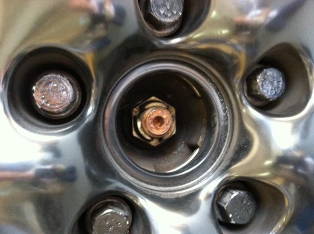
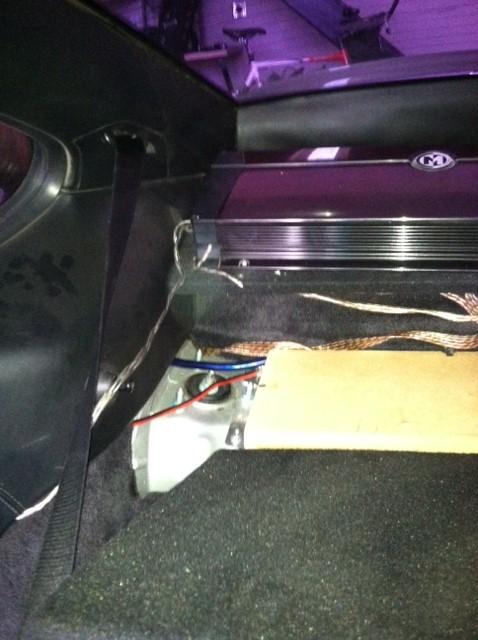
2. Before jacking up the car: (1) remove carpeting covering rear shock mounts. The carpeting is located just behind the rear seats. Just pull up from the center and work the thick padded carpeting out. It just pulls out, no clips. PICTURE 2 SHOWS THE PASSENGER SIDE REAR SHOCK MOUNT). My car is a coupe, and I believe the process is different for a cab, and if you have a Bose system, you will have to remove that first. I had a ton of stereo equipment I had to move out of the way, so this step was a bit of a hassle for me. Dont remove the three bolts yet. (2) If you have opted to undue the hub from the axles instead of removing the axles from the diff, now is the time to break lose the 32mm nuts on the front axles (SEE PICTURE 1). You will need a lot of torque since these are tightened to 350 ft. lbs. Have someone sit in the car and apply the brakes as you do this. I highly recommend using an impact gun or ¾ inch drive gear. I only used a ½â€Â breaker bar and it was flexing something fierce. I was actually scared the bar would break, so you would be well-advised to wear safety goggles or at least look away from the bar while it is flexing. (3) loosen slightly the lug bolts on all four tires.
3. Get the car up on jackstands (use your preferred method. I had a lift so it was easy.). You can do one axle at a time, or put the car up on all four. Remove all four wheels.
Rear shocks
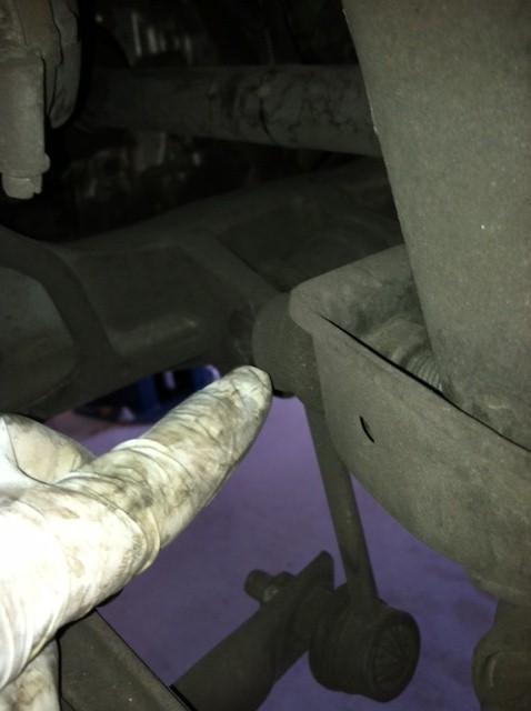
1. Remove sway bar links. With the car in the air and well supported (redundant jacks are a really good idea since you will eventually be banging and tugging on parts), undo the sway bar links from the sway bar (counter with an open end wrench to avoid just spinning the bolt in the joint). SEE PICTURE 3 (remove only the bottom link now, and not the upper link that Im pointing to in the picture, as the top one is a bit of a hassle to remove on the car and its much easier to remove it after the shock is out, at which point you should transfer the drop link to the new shock so you are ready to go upon re-installation of the shock).
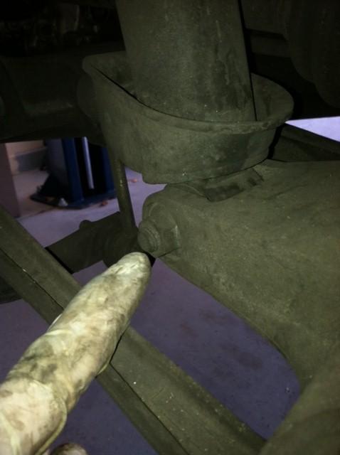
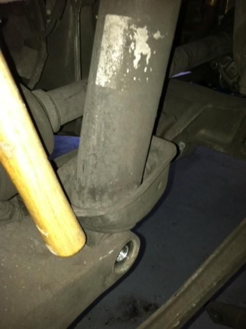
2. Remove rear shocks. Remove the 18mm (I think) nut holding the bottom of the shock to its mount on the wheel carrier, countering with a wrench to keep the nut on the other side from spinning (SEE PICTURE 4). Once the nut is out you will need to push the bolt out of the mount and the shock. On my car there was a good amount of tension on the lower shock mount bolt for some reason, even after compressing the springs. For this reason I could not just push the bolt out of the hole in the mount. So, I used a crow bar to force the entire wheel carrier assembly downward just a hair and and this took enough tension off the shock bolt to permit me to push the bolt out using a mallet and screwdriver (having a helper is really, really helpful here). (SEE PICTURE 5: disregard the large allen wrench in the hole for now that will come later).
Remove the three upper shock mount nuts located behind the rear seats, and then wiggle the shock out from under the car. The entire shock assembly should just slide and wiggle down and free of the car (you may have to knock the bottom shock mount out of the wheel carrier location if the bottom shock mount is tight in the wheel carrier mount mine was pretty tight so I had to knock the bottom mount of the shock inboard with a mallet before the shock would fall down and out from the car. On the other side, instead of knocking it out, I just used the handle of the mallet to lever the shock away from the mount (SEE PICTURE 6). Repeat for the other side.
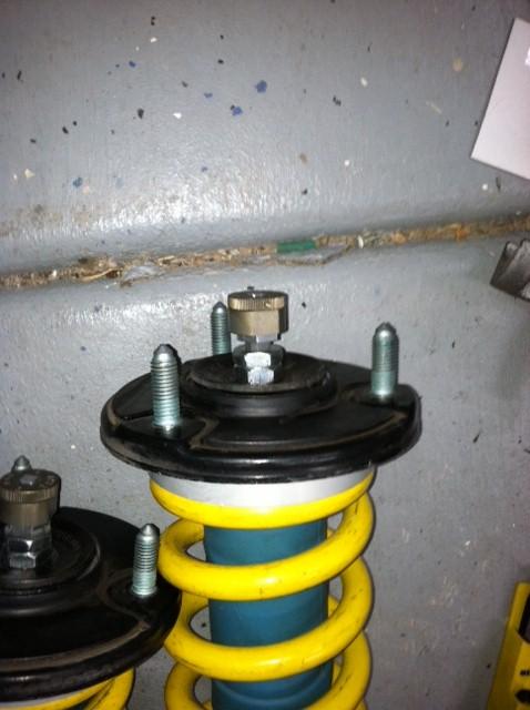
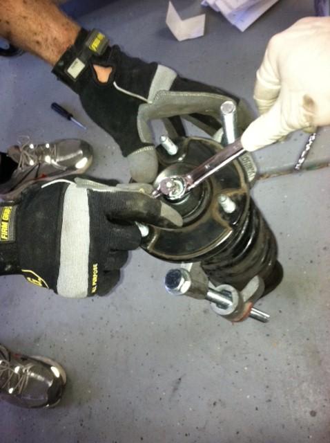
3. Transfer components to your new rear shocks. (1) If you are re-using your old sway bar drop links, transfer them over to the new shocks now. I used just a drop of blue loctite, just for the added security. (2) Next, unless your new shocks already have hats, upper shock mounts, and all the associated washers and nuts already assembled, you will need to transfer some components from your old shocks to the new ones. What you transfer, and in what order, depends on the shocks you are installing. On my psss, I transferred: (1) the upper mount that secures the top of the shock to the car (without the plastic and rubber spring perch or seat, since bilstein provides an aluminum spring seat/perch hat which replaces the oem part); and (2) the two large black, curved washers that go on both sides of the upper oem shock mount (the curve is facing up for the upper washer, and the curve is facing down for the bottom washer. PICTURE 7 shows the oem upper mount, the pss9 aluminum hat just below it, and also visible on top of the rubber portion of the oem mount is the large, black curved washer that is facing upward. On top of the washer are the two nuts that bilstein provides (I think) that secure the piston rod/bolt to the hat, and on top of that is the adjustment head assembly (which consists of a thin nut, the adjustment head body, and the knurled adjustment ****). The procedure for removing the necessary oem hardware from the oem shocks is as follows: Have a helper hold the top of the center bolt/piston rod with the correct size crescent wrench or vise grips to keep the rod from spinning while you are removing the upper shock mount center nut, then loosen the nut that holds the shock to the upper mount. SEE PICTURE 8 (a helper is needed here as well). In my case I had to use spring compressors to compress the springs and take some tension off the upper mount in order to loosen this nut. Otherwise, it would have been really tough to loosen the nut, and potentially dangerous as the shock was under a good bit of compression even off the car. After everything is apart and transferred to the new shocks, you will need to re-attach the adjustment **** to the top of the shock piston rod. This was a little tricky because you have to make sure everything is lined up and torqued down correctly, but it is not too hard with the help of the somewhat cryptic pss9 instructions (pm me if you want a scanned version of these instructions). Before you remove the spring compressors, I recommend adjusting the spring plates with some coilover wrenches so that the ride height is close to where you think you might want it to be when fully set up, since its definitely easier to make big adjustments with the shocks off the car. Dont forget to use the coilover wrenches to get the jam plate tight against the spring plate.
4. Install new rear shocks. After installing the sway bar link to the shock, snake the shock/mount/sway bar link assembly up through the bottom into place, and loosely tighten the three mounting bolts from inside of the car, in order to hold the shock in place. At this point you will need to do a little pushing and prying to get the lower shock mount into its corresponding mount on the wheel carrier. The trick is lining up the hole in the shock mount with the holes in the wheel carrier perfectly so that the mounting bolt will slide in. If these holes are not perfectly oriented and aligned, the bolt will not slide in because the tolerances are too tight. So, PICTURE NO. 5 shows how I accomplished this task, and it worked pretty well. I used a crow bar to lever the carrier down and the shock up so as to get the mounting holes in general alignment, and at that point I inserted a large allen wrench into the mounting holes so that I could lever the two holes into exact alignment so I could slide the mounting bolt in virtually friction free. Then tighten up this bolt. Finally, attach the dangling sway bar link to the sway bar but dont tighten it all the way tight, as you will want to wait to do that until there is load on the sway bar from the car (at least that is my understanding).
Front Shocks
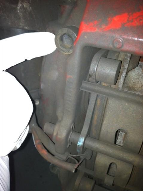
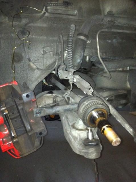
1. Preliminary Removal Steps: Remove the three top-side bolts that hold the top mounts to the car. Remove the 18mm nut that holds the carrier to the body of the strut and pull out the bolt. Unclip the two sensors that clip into the mount that is attached to the inboard side of the wheel carrier. One is an abs sensor, and the other may be a wheel speed sensor, but Im not sure. Next, remove the 10mm bolt and the 10mm nut that hold the abs sensor mount to the wheel carrier (PICTURE NO. 9 shows this mount with the two sensors). Now, remove the caliper by removing the two large, allen bolts that secure the caliper to the wheel carrier. See PICTURE NO. 10. At this point you will probably need to push the brake pads away from the rotor in order to free the caliper from the rotor (I used a large pair of pliers, taking care to protect the caliper with shop towels or other protection so I didnt damage the paint). Now you can separate the caliper from the rotor. Grab a straightened coat hanger or wire and gently hang the caliper from an acceptable location in the wheel well so as to ensure that you put no bends or undue stress on the hard brake line going to the caliper (See PICTURE 11 for the location I used to hang the caliper I didnt see any other viable location to hang from, since you are going to be removing the strut soon and cannot therefore use the shock spring for that purpose). Remove the two Phillips screws that hold the rotor to the wheel carrier/hub, and put to the rotor to the side. Finally, remove the plastic brake ducts attached to the lower control harm that direct cooling air to the rotors (use a flat blade screwdriver to unclip the ducts from behind there are two clip locations and after unclipping those you can wrestle the duct off the control arm). Remove the bolt holding the bottom of the drop link to the sway bar and disconnect the drop link from the sway bar.
2. Remove the wheel Carrier: (Note: Ive seen write ups where the carrier is not removed, but I found removing it much easier, since it involves much less risk of scratching your paint or damaging bodywork trying find an angle that permits removal of the strut out of the carrier.) This is the point in the job where things get a little more involved and tricky. Now that you have removed the top mount bolts, wheel carrier bolt holding the strut in the carrier, bottom drop link nut, rotor, caliper, abs sensor mount, axle nut (or removed the axle from the diff side, if you elect to do it that way), you are ready for the next steps.
a. Disconnect the axle. There are two approaches to this step. You can either remove the axle nut (which means you have to buy a new nut because it absolutely, positively, cannot/should not be re-used), or you can disconnect the axle from the differential by removing the 6 allen-head bolts that hold the axle to the diff (you will need a long extension, I used a 12-inch extension coupled with another 6-inch extension attached to my ratchet). If you remove the bolts at the differential, you will probably need someone to apply the brakes or at least hold the other front tire (or rotor) to keep it from spinning as you try to undue these six bolts). In Picture 11 you can make out a few of these bolts at the diff. If you opt to leave the axle attached to the diff, thread the axle nut off the end of the axle while someone holds the other tire (or applies the brakes) to keep it from spinning.
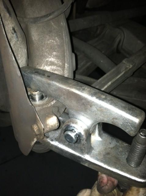
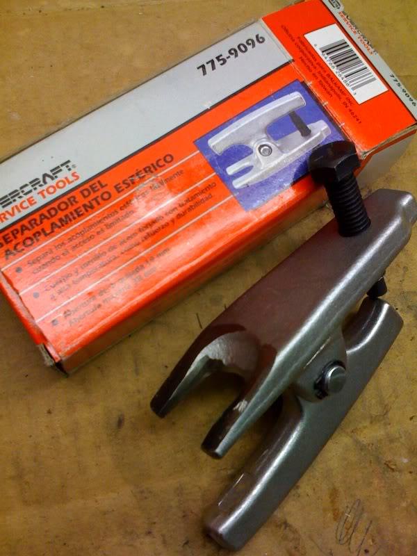
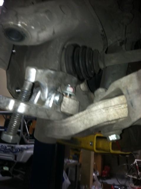
b. Remove the tie rod from the wheel carrier. For this step I went to NAPA and bought a ball joint separator tool, as recommended by jjbravo in his very informative post on the topic (see link at Love my Mode Camber Plates. Thanks Dan / Vivid !). The tool will require a bit of modification to work on this application. Namely, you need to remove the c-clip that secures the pin that holds the two arms together, flip the top arm around 180 deg, and then grind down the face of the u-shaped arm so that it is just a bit thinner (this is required because there is not much space to insert the arm of the tool into the tight spaces required to pop the ball joint out of the tie rod and control arm). PICTURE 12 shows the orientation of the tool on the tie rod bolt, and Picture 13 is from JJbravos post and shows the tool itself with the arm flipped and the u-arm ground down. PICTURES 14 shows the tool on the lower control arm ball joint, but provides a good view of how the tool should be oriented). Back off the nut holding the ball joint bolt to the wheel carrier until the nut is backed off the ball joint bolt by a few threads. Then, you are going to position the lever arm of the ball joint separator on top of the nut (this protects the bolt which is not replaceable on its own, so you dont want to damage it or you will have to replace the entire tie rod), and put the u-shaped end of the tool under the wheel carrier (being very careful not to contact or otherwise damage the boot, which is very easy to do). (See PICTURE 12 for proper orientation but dont forget to leave the nut on the top of the ball joint bolt). At this point start tightening the bolt on the tool until you get a good amount of pressure pushing on the top of the bolt. If you are (really) lucky, at this point the ball joint will pop loose, but most likely its going to be so tight that pressure from the tool is not going to be enough on its own, and I dont recommend you just keep tightening the tool as you will likely strip the threads of the tool or otherwise damage it before the ball joint comes free from the carrier. So, on the recommendation of a few members here, I did the following. Once you have a good amount of pressure on the nut on the top of the bolt, give the top of the lever arm that is contacting the nut a few good whacks with a hammer or mallet. NOW, HERE IS THE TRICK THAT WILL SAVE YOU A BUNCH OF TIME AND DAMAGED SUSPENSION COMPONENTS. Before you whack on the lever arm, support the wheel carrier in some fashion from below (i.e., with a floor jack or strategically-placed 2x4, etc, in order to put upward pressure on the bottom of the wheel carrier at a suitable location where it wont damage the carrier or slip off). If you do not do this, when you whack on the bolt nothing will happen because the entire wheel carrier assembly will just move downward with each blow. I suspect that if you support the carrier, you can get away without the NAPA tool, and could probably get the joint loose from the carrier with a few good whacks on the nut (being careful not to hammer directly on the bolt or else you could damage the threads). Once the tie rod ball joint pops loose, remove the nut and push the tie rod out of the way free of the carrier.
c. Remove the lower control arm ball Joint (See the alternative in step c(1) below for a different option that does not require undoing the ball joint). The procedure for this step is basically the same as the procedure for removing the tie rod ball joint. The only difference was that this nut/bolt is harder to access due to its location, the ball joint tool is an even tighter fit, and the ball joint seemed to be lodged onto the carrier even tighter. Once you have the ball joint knocked down free from the carrier (dont forget to support the carrier as you hammer on the top of the ball joint tool lever arm), you should be able to lift the wheel carrier up and off the lower control arm ball joint bolt, and carefully remove the wheel carrier together with the strut (the axle will stay attached unless you removed the bolts holding the axle to the differential. If you removed the axle nut the axle will just slide out of the carrier). On my car I had to put a fair amount of downward pressure on the control arm to achieve enough clearance to get the carrier up and off the ball joint bolt. I accomplished this by myself with the use of a crow bar to lever the control arm down, but if you have a helper you probably wont need a crowbar. ONE POINT OF CAUTION HERE. It is very, very easy to damage the lower control arm ball joint boot when you are trying to wiggle out the carrier, especially since there is a fairly sharp brake shield attached to the carrier at this location. I was very cognizant of this risk and still managed to put a slice in the boot (probably because I was working by myself at this point another set of hands would have really helped here). You do not want to cut the boot because neither the boot nor the joint are serviceable, meaning that you are looking at a new control arm if you damage the boot. Im cheap so I put some shoe goo on the little slice and Ill replace when the joint starts to wear, make noise, or cause a shimmy. Once the carrier is out you will be able to slide the strut completely out of its mount by sliding the strut upward.
c(1). Alternative to Removal of the Control arm ball joint. After I spoke with my tech about my ball joint boot mishap, he advised that its usually quicker, easier, and safer to leave the control arm ball joint intact with the wheel carrier, and just remove the bolt holding the control arm to the frame. That way, when you remove the carrier, the control arm comes with it and you dont have to worry about damaging the boot or the joint by whacking on things with a hammer. In retrospect, I wish I would have gone this route. Because I did not try this method, I cant document how easy it is or is not, but it seems easier and appears to involve only the removal of a single bolt. If someone can confirm, feel free to chime in.
3. Assemble wheel/carrier coilover strut assembly. If you are transferring the top mounts from your stock struts to the new struts, now is the time. I imagine the procedure for doing so is similar to the procedure for the rear shocks (albeit a bit simpler since you dont have to mess with the adjustment **** since on the pss9s the front struts feature the adjustment **** on the bottom). However, my front pss9s came assembled with the mounts, so Im not positive which washers, spacers, nuts, and bolts are transferred over. I do know that there is thrust washer that comes from bilstein that absolutely must be installed, in the right location and in the correct orientation (its curved), or you will have problems, so pay attention here. Once the struts and top mounts are joined, and with the springs still compressed a bit to make it easier to tighten everything down, adjust the spring plates to approximately the ride height you want, so as to minimize the amount of adjusting you have to do after install. Once the strut is assembled slide it into the carrier and tighten down the bolt and nut that hold the strut to the carrier. Finally, loosely attach the bilstein supplied drop link (or your adjustable drop links) to the drop link attachment point on the strut. Dont tighten all the way yet.
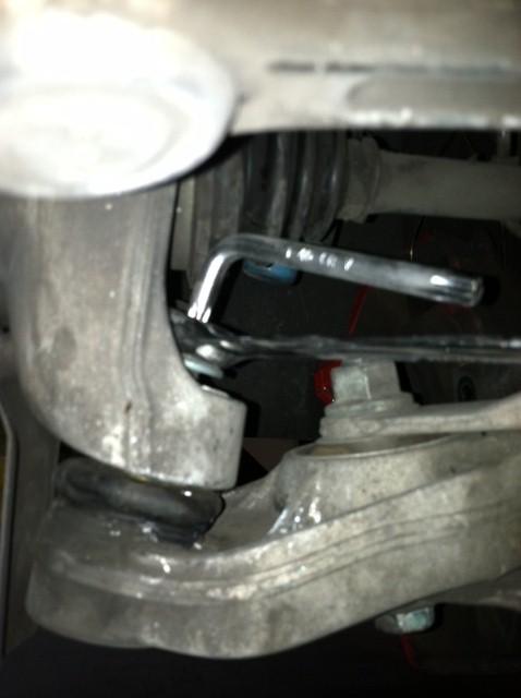
4. Install the Strut/Wheel carrier assembly into the car. You are now ready to re-install the carrier. There is a little arrow on the top mount that must be facing forward, so make sure the orientation is correct (its hard to screw this up though, as the wheel carrier only goes on one way and the mount in the carrier indexes with the mounting hardware welded to the strut body). This part is a bit tricky and is definitely easier with two people. Angle the top of the strut into the wheel well and line up the three studs on the top mount with the three holes in the body. If you removed the axle from the carrier as opposed to removing the axle from the diff, insert the splined end of the axle into the hub before this step. If you popped the lower control arm ball joint, meaning the control arm is still attached to the frame, apply downward pressure on the control arm so that while you are keeping the top mount studs in their respective holes, you can create enough of a gap to lift the wheel carrier above and onto the control arm ball joint bolt. If you dont have a helper you will need a crowbar to lever the carrier up and onto the ball joint bolt/stud. I imagine that if you removed the control arm from the car you would need someone to support the control arm and wheel carrier while you reattach the control arm to the frame. At this point loosely attach the top mount to the car by threading the nuts onto the studs of the mount, just to hold everything in place while you finish the install. If you removed the axle form the diff now is the time to tighten the 6 allen bolts that hold the diff to the axle. If you removed the control arm ball joint you will need a torx wrench that has a 90 degree bend like an allen wrench, which is how you keep the ball joint bolt from spinning while you tighten the ball joint nut down (if you dont counter, the bolt will spin at least it did for me, although Ive seen at least one report that someone was able to get away with tightening without countering with the torx wrench). See Picture No. 15 (sorry for the poor pic quality…the picture shoes the torx wrench countering against the open-end wrench Im using to tighten down the nut, but its a bit hard to make out the wrench on the nut). Once the control arm or control arm ball joint is properly tightened down, go ahead and tighten the top mount bolts and the 18mm nut that secures the strut to the wheel carrier. Next, insert the tie rod ball joint bolt up into its mounting hole in the wheel carrier, and use the same procedure to tighten down the nut (countering with the special torx wrench so the bolt doesnt spin). At this point, you can re-install the rotor, brake caliper, abs sensor mounts and sensors, taking care to get everything tightened to spec. If you removed the axle nut, get it as tight as you can now before the car is on the ground.
FINISHING UP.
Check all the bolts you removed to ensure they are tightened to spec. Leave the drop links unattached to the sway bars for now. Reinstall the wheels, get the car on the ground, and if you removed the axle nuts have a helper apply the brakes while your torque (the new) axle nuts to 340 ft. lbs. Get on the ground and thread the drop link bolt into the hole of the sway bar, and tighten. Also reach your socket set into the wheel well and tighten down the top drop link mount.
Thats It. At this point your alignment is going to be a mess, so resist the urge to go bomb the backroads, and drive the car to your local shop to get it aligned and corner balanced. I also had my shop (Robert ant EVOMS!) double check my install to make sure torque specs were accurate and I didnt screw anything up too badly. Aside from a few bolts that were not tightened to spec, he said everything looked pretty good. Robert aligned and corner balanced, set the ride height, and the car feels great.
It is currently set to 6 in the rear and 4 in the front, and it feels much firmer than stock but in no way harsh or abrupt, like my 88k mile old units felt over expansion joints and other abrupt bumps and potholes. Body roll is greatly reduced, and so is the hallmark front end jump when you goose it (people in front of me used to think I was flashing my brights when I got on it!). The car also launches much better and harder, since there is so much less slop in the suspension to absorb all the forward energy. Ive also noticed my shifts feel much crisper (especially the 1-2 shift) when engaged in spirited driving. Oh yeah, and the car looks amazing with the 4x4 stance vanquished. Im a happy camper.
If you have helpful hints or advice (or corrections), please feel free to post them up. This was my first real suspension job Ive undertaken (except for an easy swap on an old bmw 318ti), so I was a bit intimidated. Although there are a lot of diys on the forum, none were very detailed, and Im a detail kind of guy so I thought Id spell out the install in excruciating detail. Hopefully it will inspire some newbie mechanic like myself to save some dough and go for it. Im glad I did. Good luck.
Powered by Froala Editor