You must be logged in to rate content!
19 minute read
DIY Alignment Equipment; maybe not as good as hoped
Compliments of Argess @ http://www.hotrodders.com
5-14-2013
Here’s three suspension/alignment DIY projects that may be of interest. Or at least good for a laugh! Although they all work, none are particularly successful when consideration is made to accuracy and ease of use. But they were fun to make and I learned a few things.
Wheel Weight Gauge
A while back, I became somewhat interested in corner weight balancing. I found it somewhat confusing as there appeared to be two different points of view in performing the calculations. Fred Puhn, in his book “How To Make Your Car Handle” (1981) prefers setting the left front to rear ratio the same as the right front to rear ratio. The current, and predominate method, is to target for a 50% cross weight balance.
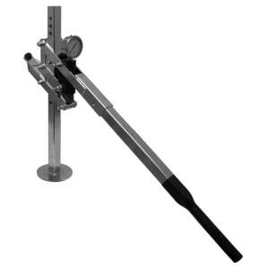
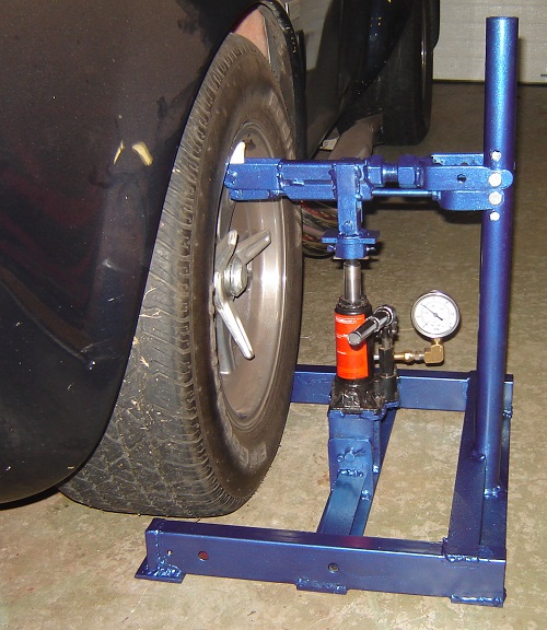
I thought I’d like at least see what my corner weights were, and that would take a set of scales. A little investigation showed them to be too expensive for probably a one time use, so I looked at other possibilities. It was suggested to me to look into building one of those home-made lever units, utilizing an old brake or clutch cylinder and a pressure gauge. Here’s one type:
I didn’t like it much, as trying to maintain the tire “just off the floor” as well as trying to read a small gauge with my far-sighted vision, wasn’t for me. So I came up with another idea, sort of like a mini-engine hoist. Here’s the basic idea in a theoretical sketch:
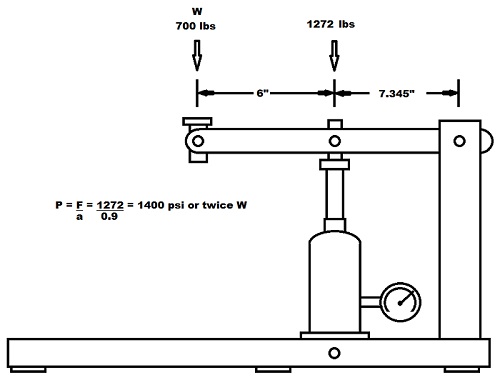
The lever length is adjusted so the pressure gauge will read twice the weight (but of course in psi).
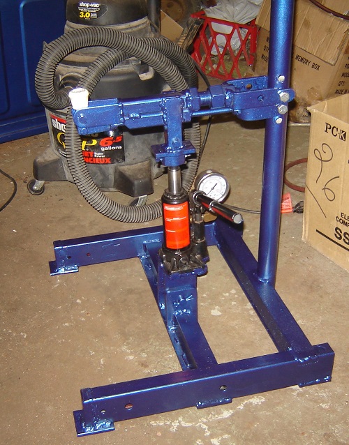
Now I had one guideline to follow with all this (besides Safety), and that was minimum expense as if it didn’t work, I didn’t want to be out much money. My only real expenses were the bottle jack ($16) and the 2000 psi pressure gauge ($13). As you can see in the picture below, it looks quite odd, but a lot of that is I used what I had... bits from an old broken exercise machine, old rusty flat plate and angle iron, old nuts and bolts, etc. I even painted it, and the spray can came from an unknown history (can’t remember why I bought it many years ago).
(Please don’t look too closely at the welding….LOL)
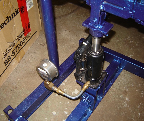
In the next pic you can see how I modified the bottle jack, at least externally.
I did find a YouTube video on this type of thing, but I was a little bit misled by one part. The fellow says to measure the bottom of the hydraulic ram to find the cross-sectional area. This does not appear to be correct. The inside diameter of the cylinder should be measured instead, and the area calculated from that. In fact, as the area is proportional to the radius squared, it doesn’t take much error in your diameter measurement to put things out quite a bit. It is best to determine the effective area by test, and then use that to work out the lever lengths of the lifting arm. Here’s a link to the YouTube video:
In the next pic, you can see my little Corner Jack in use. Basically, I lift the tire off the floor, slide a piece of paper under the tire, and slowly lower the tire back down until the paper starts to feel tight to slide around. It’s like using a feeler gauge to check valve lash. (yes, the car is dirty with bug splatter, grime and other stuff!)
…and now comes the real problem. As you raise the tire, you also raise the whole car, and where do you stop to take a reading as the gauge just keeps reading higher the more you lift the wheel. The hope is because you are making the same error in every wheel, they will cancel out…. Well, that’s the hope anyway.
There’s a small problem with repeatability, mostly to do with the fact I didn’t grease or oil any of the pivot points yet, however it wasn’t bad as long as I always released the pressure until the paper felt friction with the tire, and didn’t try raising the tire until the paper became free.
Another issue is trying to make small measurements on the gauge. Not good as the gauge resolution in graduated in 50 psi increments (which equates to 25 lb increments of wheel weight). However, it’s not too bad judging partial readings.
I did make take some readings today, although they aren’t quite right as I didn’t disconnect the anti-sway bars. This is a very noticeable factor with the front wheels and the numbers are way too high. The rear suspension, with its much smaller sway bar yielded numbers closer to what is expected.
I know the numbers are way to high as if I add the total of all four wheels, I get more than the car is expected to weigh. This is a problem when jacking up a single wheel, although I expect better results with the anti-sway bars disconnected.
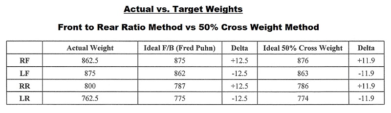
Here’s the results of my numbers. I calculated the Front/Back method using Fred’s book as a guide
I admit to getting lazy with the 50% cross weight method and used an on-line calculator which can be found here:
I find it quite interesting that both methods yield such a close result. A change of 12.5 lbs per wheel with Fred’s method and 11.9 with the cross weight method.
In either case, the results looks pretty good, although more variance may show up once the anti-sway bars are disconnected.
The odd thing to me, is it seems sort of senseless to make the measurements with the driver (me) or equivalent weight, in the car for public road use with a two-seater car. Because the driver and passenger weight can change, I think it‘s best to corner balance with no-one in it. I seem to remember Des Hammill saying more or less the same thing in his Suspension book for Sports and Kit Cars.
Because the driver and passenger weight can change so much, I would suspect the 12.5 or 11.9 lbs is probably negligible. I’m sure it’s a different story for the track, but I don’t think I‘ll ever do that.
Overall, my Corner Weight Gauge was a fun thing to design and build, but I don’t think it’s accurate enough to do more than get “close”. The whole concept of jacking up one wheel at a time has an inherent error plus the gauge doesn’t have very good resolution.
However I suppose I can be satisfied with the results I have. At least I know I don’t have a drastic mismatch with corner weighting. All for $29 and a little elbow grease.
Castor/Camber Gauge
This recent project was to make a castor/camber gauge. There are commercial gauges available, but making one from old scrap (so no cost) as well as having a bit of fun seems to intrigue me more.
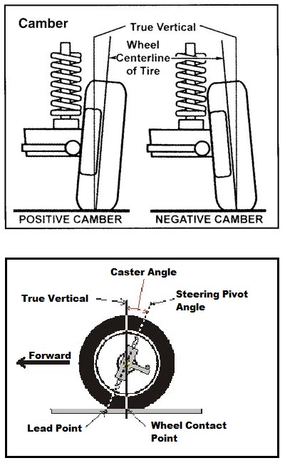
Camber is the easy one to grasp. It’s simply the angle the wheel leans in or out from vertical. Castor is same as the kingpin angle fore and aft, if one were to be actually using kingpins, however it wasn’t so easy to figure out how to measure it with the wheels on. More on that further down.
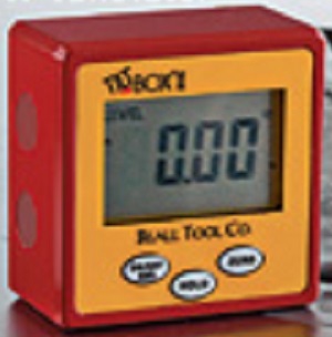
I have a digital angle level gauge, which I see is getting less expensive these days depending on where one purchases it. I’m not counting the cost of it in this project as I already have it for other purposes:
Next I needed to make some sort of bracket that can be fastened to the wheel. I wanted a bracket that would stay fixed without holding it. My basic concept is shown here (note moving the lower arms to their 120 degree positions causes the rubber wheels to push harder against the rim):
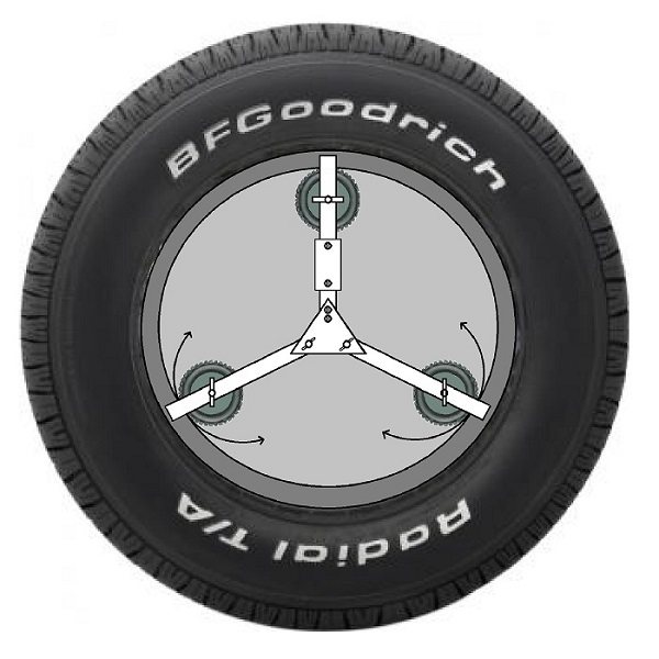
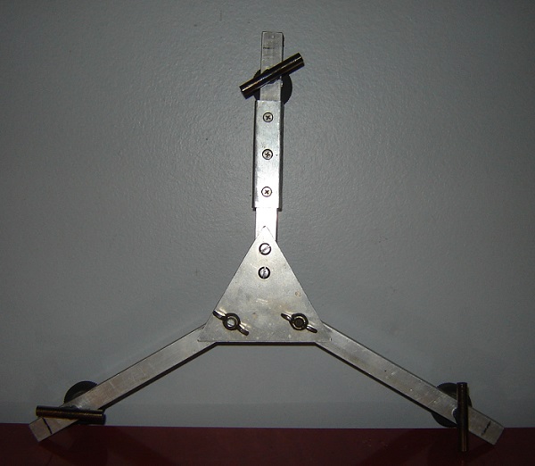
The actual finished unit is shown here:
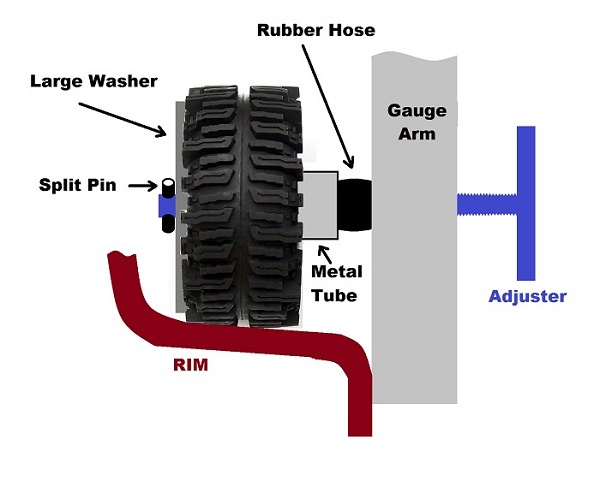
I did have one setback. Once I installed the first version, I noticed the arms would spring away from the wheel rim outer edge about 1/32”. I didn’t like that, so came up with a modification where I could turn a few screws to pull in the gaps. I could have used springs, but went with a bit of rubber hose instead:
Here’s a pic of the finished assembly:
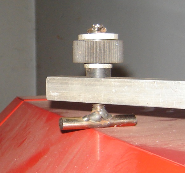
And here’s the final bracket installed with gauge. I had to add a thin steel plate to the aluminium arm so the Indicator built in magnets had something to hold on to.
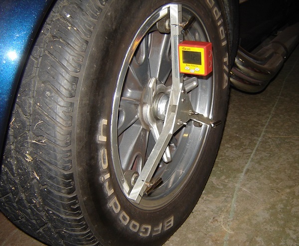
Many commercial gauges require you to rotate the wheels to the right and left, 20 degrees each way and read total castor from a scale. Sweeping over this 40 degree arc effectively eliminates the camber angle from the equation.
Here’s a pic of a commercial gauge which uses a +/- 15 degree sweep. Note the same bubble tube is used for both measurements, but the castor has twice the number of degrees compared to the camber measurement.
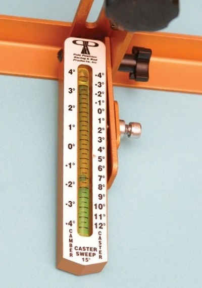
If we take a hypothetical high castor angle of 8 degrees, as measured through a 30 degree sweep, the camber gauge will read 2 degrees (not counting the actual camber) over 15 degrees of steering angle.
… and 2 divided by 8 = Sin (15) Actually it is more like 14.5, but the error is small so they rounded it off to 15 degrees.
When I use my gauge, I’ll check the gauge at +15 and then again at -15 (with 15 degree chalk marks on the floor). I’ll add the two together and divide by 2 to get the average reading, thereby eliminating any camber.
As the Sin 15 will be approx 0.25, my Castor will be = 2*(reading at pos 15 + reading at neg 15)
For example, if I have a neg 15 reading of 2.5 and a pos 15 reading of 1.5 (Camber is -0.5 degrees), my Castor will be 8 degrees. A double check shows my swing of +/- 2 degrees divided by 8 degrees yields 0.25 or the Sin (15 degrees).
The next step will be to level the car and make turntables. There is a Youtube video on this where the fellow finds the floor height at each wheel relative to the highest point with a homemade manometer, and uses stick-on floor tiles to make up the difference. He makes pivots for the tires out of two floor tiles with table salt in between. You can use grease although I can see it being messy. The salt idea is clever though.
My next project will be some sort of Toe-In gauge which ought to better than the piece of plywood I previously used to set the toe.
Toe-In Gauge
After finishing my toe-in gauge I have to admit it isn’t one of my better accomplishments. I failed to follow the KISS principle and wound up with something overly complicated, made it from what I had laying around which isn’t as rigid as I would like, both calibration and set-up are a bit touchy, and during the project, I found a method much easier that I should have used, but kept going anyway.
Basically, I wanted a method that I could use without a helper. It can be a bit tricky using a tape measure by yourself and even if you hook it to toe plates or weight the tape down, it can still move. It’s one thing to ask for help bleeding the brakes because that’s a quick thing to do. It’s another thing to ask for a rather long time commitment as I make measurements, make adjustments, and then repeat many times until the job’s done.
I also wanted to use up junk-box parts and scrap material I had laying around. In fact total cost was $3 for a cheapie laser level at the second hand store and $6 for the mirror. I think that even at full price these levels are usually under $20 unless you buy one with the tripod.
But before I get into this project, a bit about toe-in.
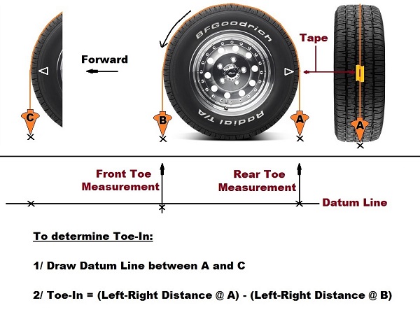
As far as I can tell the basis of measurement is the difference between the track across the front of the tires and the track across the rear of the tires. Not everyone seems to use this method and there’s a lot of erroneous methods on the net that can result in low or high results compared to what the toe actually is. I think it would be best if everyone did away with toe-in as a linear measurement and just specified an angle instead.
I did some research and did find lots of good ideas (some much better than mine… sigh), but wound up fixated on some sort of laser measurement. High tech and all that sounded great, but at least it’s easier than using string.
My favourite is the plumb-bob method (or you can use a carpenter’s square), and is shown below. Unfortunately every description I read doesn’t use point B, but merely points A and C. As far as I am concerned, this will not yield correct results. The fore and aft lines need to be apart by the tire diameter. However, one still needs to deal with a tape measure, and that means either a helper, or some weights to help hold the tape in place.
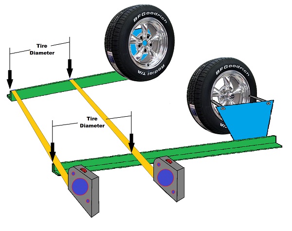
Toe-Plates form the basis for most gauges, as per the simple sketch below. Building them would have been enough as they turned out heavy enough not to move if I was careful with the tape measure. My main error was not using square or rectangular tubing during construction. I should have bought some, but that goes against my grain when trying to build something that might not work. I used heavy angle-iron and thick aluminum plate, but as it can flex a bit, I have to be careful when setting things up.
Below is the theory of a laser gauge. You calibrate the system with the toe plate rails parallel, and when measuring toe-in, you reposition the laser so the reflected beam hit’s the same calibration spot. The laser will then be at the same angle as the tires, or so I thought. More on that shortly.
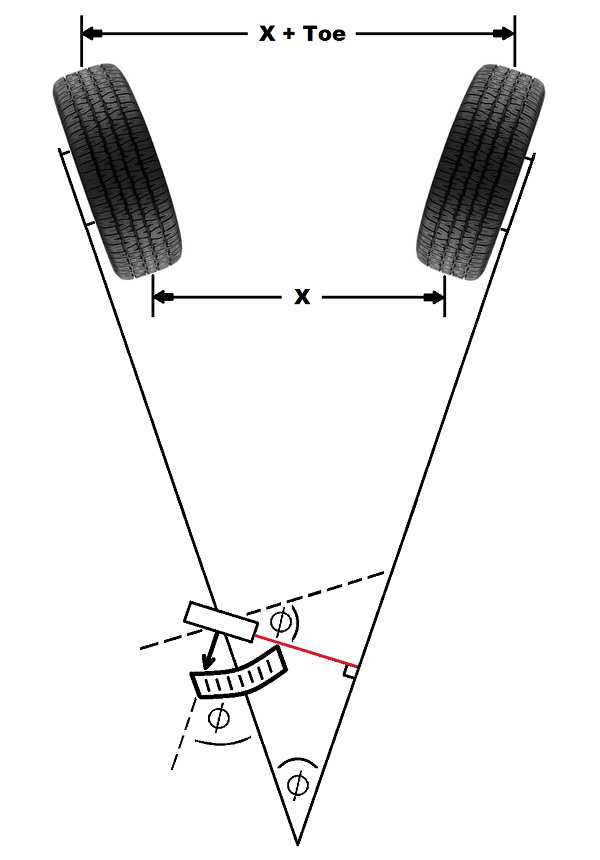
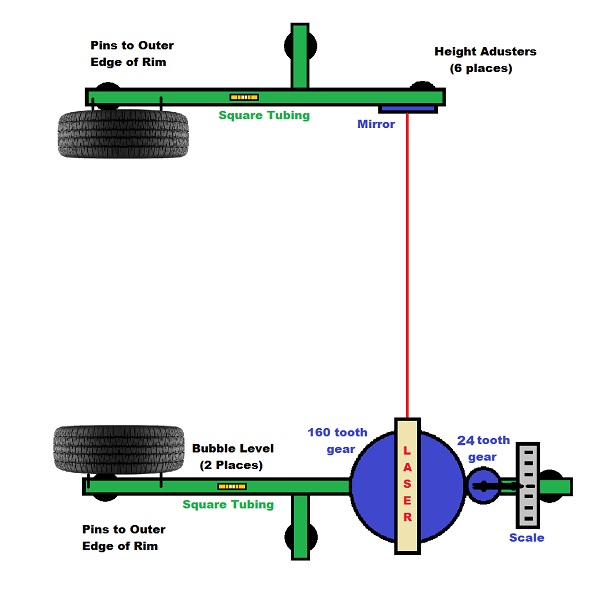
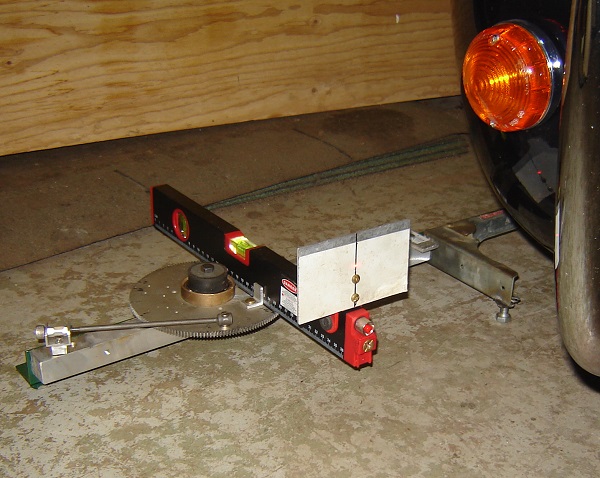
Here’s a sketch of what I planned to make. It’s similar to other designs, but doesn’t use a dial indicator. Instead it uses a 160:24 gear ratio to multiply the angle by a factor of 6.667 making it easier to read. The pointer arm length is calculated to 7.8” so the scale is doubled to the actual toe-in, i.e. a 1/4” reading on the gauge indicates 1/8” of toe. This does not rely on the car’s track, but does rely on knowing the tirediameter (in my case, 26”).
And here’s the final, none-too-pretty, result:
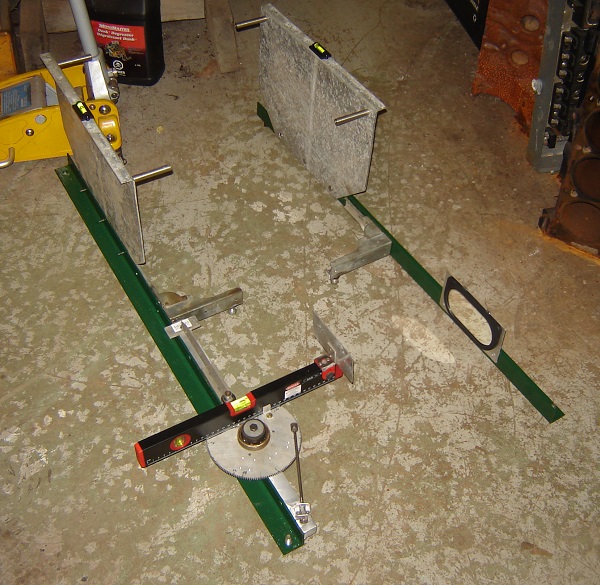
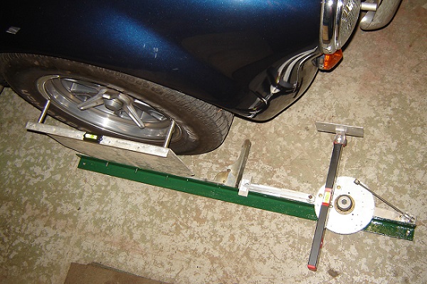
Here is the laser side installed against the wheel rim. Not a super quick job as there are 5 points to consider, making a 4 legged chair look easy.
And another view:
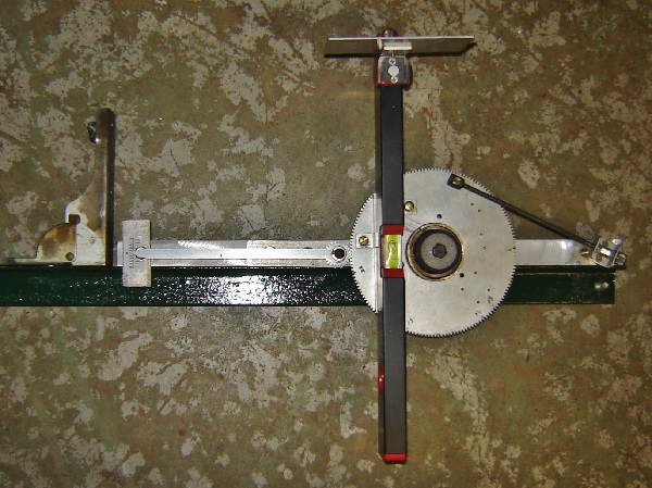
Here’s the laser unit. Notice the laser is rotated by use of a thumbwheel. There is very little hysteresis with it, although it won’t affect the reading as there is no hysteresis between the laser and the pointer as all the gear lash is removed (small gear is on a moveable plate for this purpose).
The laser is mounted from underneath using it’s tripod hole and with the pointer at zero and the rails precisely parallel, the little angle brackets are moved back and forth as required.
All in all, it does work, although I did have one problem. First I measured the toe-in using my gauge and then I did the plumb-bob method (which I highly recommend) and unfortunately the toe-in was different by a small, but unacceptable amount. I double checked the plumb-bob measurements and gave some thought to any flexing with my gauge parts, but couldn't pin anything down.
Eventually I realized it was all in the calibration. When I originally calibrated my gauge, I did it with the two parts parallel and adjusted for zero. This wasn't accurate for two reasons.
The first is because extruded angle iron has rounded edges and not a sharp edge to match up with the tape measure markings, but it's not much of an error. Plus I should have measured at the rim pins instead.
However the main reason was that calibration should not be done with the two pieces parallel and adjusted for zero. It is much better if the two parts are angled to a specific toe-in, the gauge adjusted to read that toe-in, and the laser aligned so the return beam is centered on the target line.
Without getting into it too deeply (as I havn't fully thought it out myself yet), the best analogy I can think of is a piston and crankshaft. When the piston is near TDC, any up or down motion is hard to visibly detect despite moving the crankshaft a small amount. Yet, if the piston was halfway though the stroke, the same small crankshaft rotation moves the piston an easily discernible amount (or you can picture a Sine wave).
To make calibration easier, I made a couple of alignment rods. They are thin-wall metal tubing (old tent poles) that fit over the rim pins. They are of different lengths to match the maximum toe-in on my gauge scale. It's all calibrated now and indicates the same as the plumb-bob measurement and if I set the gauge parts parallel, it still reads zero.
I’m starting to feel better about using the gauge. I find it quite quick to set-up and use now that I'm more familiar with it. Repeatability is quite good. I think I'll use it to adjust my car's toe-in, but at least for the first time I'll do a final double check with the plumb-bob.
And that’s the end of my DIY equipment. I don’t recommend building any of it unless you can add improvements, but I hope you found it interesting none-the-less.
*****************
Special Note on the Plumb-Bob Method:
I only used one plumb-bob instead of the two shown previously. I only had one for starters, but with two you need to adjust the string length very carefully so each plumb-bob is close to the floor to make your marks precise.
I just used a heavy nut to counter-balance the plumb-bob. It doesn't have be exactly the same weight as the friction of the string against the tire makes up the difference. Plus the nut can hang quite far off the floor and not cause a problem... meaning an accurate string length isn't terribly important.
And you do need space for the plumb-bob method. The car rolls ahead 1/2 tire circumference and that's almost 41 inches. And then of course it needs to roll well back so you don’t have to feed the tape measure under the car and look at marks from an angle. Lots of room needed.
Powered by Froala Editor